assembling and parameters setup for quadcopter (dji...
TRANSCRIPT

ASSEMBLING AND PARAMETERS SETUP FOR QUADCOPTER (DJI NAZA-F450 ) USING TRANSMITTER (FUTABA T10 J) AND RECEIVER (R3008SB)
MARCH 13, 2017
UNIVERSITÄT BREMEN
Parallel Computing for Embedded Sensor Systems

www.pcessflight.com
1
Contents CHAPTER 1 ............................................................................................................................................... 2
ASSEMBLY & CONNECTIONS ............................................................................................................... 2
PORT Description ............................................................................................................................. 2
Hardware Connections .................................................................................................................... 3
Esc Configuration We Used ............................................................................................................. 3
Main Controller(MC) Mount ........................................................................................................... 3
Power Management Unit (PMU) Module Mount ........................................................................... 3
GPS/Compass Mount (Optional) ..................................................................................................... 3
Transmitter(TX) & Receiver(RX) Connections ................................................................................. 4
CHAPTER 2 ............................................................................................................................................... 5
LINKING OF RECIEVER AND TRANSMITTER ......................................................................................... 5
10J Transmitter Specifications......................................................................................................... 5
R3008SB 2.4GHz T-FHSS 8-Channel Receiver .................................................................................. 7
LINKING OF RECIEVER AND TRANSMITTER ..................................................................................... 7
TRANSMITTER CONFIGURATION SETTINGS ........................................................................................ 7
CHAPTER 3 ............................................................................................................................................. 11
ASSISTANT SOFTWARE INSTALLATION AND CONFIGURATION ......................................................... 11
SOFTWARE AND DRIVER INSTALLATION ....................................................................................... 11
CONFIGURATION BY ASSISTANT ON A PC ..................................................................................... 12
CHAPTER 4 ............................................................................................................................................. 13
BASIC FLYING ..................................................................................................................................... 13
CONTROL MODE KNOWLEDGE ...................................................................................................... 13
START & STOP MOTOR KNOWLEDGE ............................................................................................ 13
COMPASS CALIBRATION ................................................................................................................ 14
ASSEMBLY CHECKING LIST ............................................................................................................. 15
LED DESCRIPTION .......................................................................................................................... 16
www.pcessflight.com
2
CHAPTER 1
ASSEMBLY & CONNECTIONS
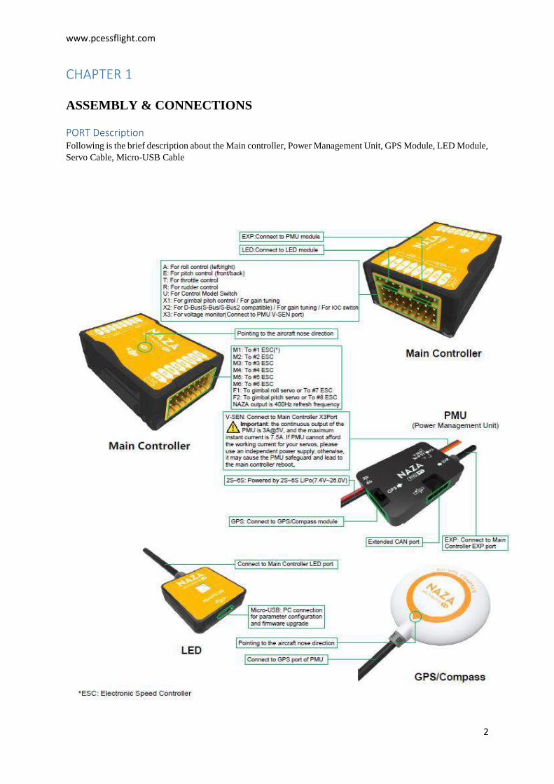
PORT Description
Following is the brief description about the Main controller, Power Management Unit, GPS Module, LED Module, Servo Cable, Micro-USB Cable

www.pcessflight.com
3
Hardware Connections
The direction of the arrow in diagram indicates the rotation direction of the motor/propeller.
Esc Configuration We Used
We used Quad Rotor X Configuration in our case that is on 2nd place in the above picture. And Motor1
(M1) is Connected to M1 input on the controller and same procedure is followed for the rest of three
Motors.
Main Controller(MC) Mount
(1) The DJI logo should face the sky, DO NOT mount the MC upside-down.
(2) The MC sides should be parallel to the aircraft body.
(3) The arrow should point to the nose direction of aircraft.
(4) The MC is best positioned near the aircraft’s center of gravity. Make sure all ports are accessible.
Tip: It is recommended to fix the MC until all wirings and configurations are completed, using 3M gummed paper provided to fix the MC.
Power Management Unit (PMU) Module Mount
DO NOT attach the PMU on other device. Sufficient air flow over the PMU is highly recommended. Tip:If use with DJI multi-rotor, you can solder the power cable to power pads on frame bottom board. Please refer to DJI multi-rotor manual for details. If use with 3rd part aircraft, you can make a connecter by yourself to connect PMU and battery.
GPS/Compass Mount (Optional)
GPS/Compass is sensitive to magnetic interference, should be far away from any electronic devices. If you use your own mounting rod, make sure it is NOT magnetic!
Procedures:
(1) You should use epoxy resin AB glue to assemble the GPS bracket first. Mount the bracket on the center plate of craft. Position the bracket at least 10 cm from any propeller.
(2) The DJI logo marked on the GPS should face the sky, with the orientation arrow pointing directly forward. then fix the GPS on the plate of the bracket (by 3M glue provided).

www.pcessflight.com
4
Tip:The GPS/Compass is packaged with a special indication line for mounting for the first time.
Transmitter(TX) & Receiver(RX) Connections
(1) Refer to you TX Manual, setup the Aileron, Elevator, Throttle, Rudder channels on your TX first, and choose a 3- position switch as control mode switch.
(2) Attach the matched RX to aircraft, then connect your RX to the right ports on MC. The following diagram shows the connection example for traditional RX.
Step3 Double Check:
In this step, turn on the transmitter, connect the battery to the PMU, and then watch the LED, if you can see the LED blinks the system is working.

www.pcessflight.com
5
CHAPTER 2
LINKING OF RECIEVER AND TRANSMITTER
10J Transmitter Specifications Type: 2-stick, 10-channel T-FHSS / S-FHSS / FHSS selectable Current Drain: 140mA System features
Futaba T-FHSS, S-FHSS 2.4GHz security
Airplane, heli, glider and multi-rotor software
30-model memory
S. Bus capable T-FHSS receiver
Telemetry
Synthesized voice for telemetry data
Vibration alerts for alarm conditions and low battery
User-updatable software (requires optional CIU-2 interface)
Wireless data transfer among 10J transmitters
Built-in S. Bus programming link for S. Bus servos
10-character model and user naming
Large (128 x 64 dot) backlit LCD display
Built-in diversity antenna
Jog dial and 3 buttons for fast, easy programming
Sub-trim and fail-safe (all channels)
Trim step adjustability
Trainer system
Throttle cut
2 count-up/-down timers + integrated timer
Model timer
Range check mode
10 channels (one variable knob, five 2-position switches, two 3-position switches, one
Servo reversing, endpoint adjustment, digital trims, dual rates/exponential* & ATL
momentary switch, two digital levers)
Servo cycle w/bar graph displays
Assignable switch/lever/functions (Ch. 5-10)
Here are just some of the functions you'll find on the 10J:
The large backlit LCD display helps make
programming easy, as well as clearly showing
the timers and telemetry data.
Aeroplane mode

www.pcessflight.com
6
Multi-Rotor mode
Helicopter mode
Model Type Selection Menu
Mutli-Rotor Center Stick Alarm
Telemetry Menu
(Must use with Futaba sensor)
Receiver Type Selection Menu
Glider Butterfly Setup Menu
5-Point Throttle Curve
Programmable Mixing
Built-in S.Bus Servo Programmer

www.pcessflight.com
7
R3008SB 2.4GHz T-FHSS 8-Channel Receiver The R3008SB is a T-FHSS telemetry-capable receiver that features S.Bus and S.Bus2 compatibility and 8 conventional ports. The receiver also features an external battery voltage connector. With S.Bus function, you can control more than 8 servos with S.Bus hub. Type: Full-range flight receiver Modes: T-FHSS Features: High-voltage operation, frequency-hopping Spread Spectrum design, Dual Antenna Diversity, S.Bus and S.Bus2 compatibility Voltage Input: 4.8V-7.4V battery or regulated output from ESC Compatible Batteries: NiCd, NiMH, LiPo, LiIon or LiFe Dimensions: 0.98 x 1.69 x 0.55 in (24.9 x 42.8 x 14.0 mm) Weight: 0.34 oz (9.5 g)
LINKING OF RECIEVER AND TRANSMITTER
1 Place the transmitter and the receiver close to each other within one meter.
2 Turn on the transmitter and the receiver.
3 Push and hold the Link switch on the receiver.
4 When the link is complete, the LED on the receiver changes to solid green.
* Please refer below for LED status and receiver condition.
No signal reception: Red On
Receiving signals: Green On
Receiving signals, but ID is unmatched: Green Blink
TRANSMITTER CONFIGURATION SETTINGS
Turn on the transmitter and you will look display like this
Step 01: Select the Model on your Transmitter and then press Execute.

www.pcessflight.com
8
Step 02: Select the Execute parameter on your Transmitter and then select the Multicopter.
Step 03: Select the Model Name According to your choice.
Step 04: Select the Aux channels.

www.pcessflight.com
9
Step 05: Select the End Point.
Step 06: Select the P-Mix 1--6. And then change the parameters for mix-1, mix-2, mix-3, mix-4, mix-5,
mix-6 one by one.

www.pcessflight.com
10
Step 07: Select the Servo. And then observe the movements by moving the joystick and verify if it is
correct or not.

www.pcessflight.com
11
CHAPTER 3
ASSISTANT SOFTWARE INSTALLATION AND CONFIGURATION
SOFTWARE AND DRIVER INSTALLATION
Note: The installer in EXE format is supported on Win XP, Win7, Win8 (32 or 64 bit)1.
1. Please download the driver and the Assistant installation software in EXE format from www.dji.com.
2. Switch on the transmitter and then power on your autopilot system.
3. Connect your autopilot system and PC via a Micro-USB cable.
4. Open the driver installation software and follow the instructions to complete installation.
5. Run the Assistant installation software and follow the instructions to complete installation.
1 For Windows 10, a suitable driver needs to be installed following the instructions at:
https://flitetest.com/articles/dji-naza-m-windows-10
https://www.rcgroups.com/forums/showthread.php?2462912-DJI-and-Windows-10

www.pcessflight.com
12
CONFIGURATION BY ASSISTANT ON A PC
1. Power on the PC. Make sure your computer is connected to the Internet for the first time you use.
2. Switch on the transmitter first, and then power on the autopilot system. Connect the autopilot system to the PC with a Micro-USB cable. DO NOT break the connection until setup is finished.
3. Run the Assistant Software.
4. Observe the indicators on the left bottom of the software. (They are the connection indicator and communication indicator in order.) If the communication indicator is blinking, that the software is ready,
please go to next step.
5. Select the “Info” option. Check the software firmware version. If the upgrade is available, you may update the assistant software.
6. Select the “Upgrade” option. Check the Main Controller, GPS and IMU firmware version.
7. Select the “Basic” option. Please follow step-by-step for your first-time-configuration. Basic configuration is necessary, including Mixer Type, Mounting, RC, and Gain settings.
8. You can click the “Advanced” option for more parameter settings. Advanced setting is optional. There are settings of Motor, Failsafe, Intelligent Orientation Control (IOC), Gimbal, Low-Voltage Alert, and Flight Limits. Read the instruction in the assistant software to obtain more details.
9. Select the “Viewer” option to check all parameters.
10. Then break the Micro-USB cable, power off the aircraft. Finished.

www.pcessflight.com
13
CHAPTER 4
BASIC FLYING
CONTROL MODE KNOWLEDGE
START & STOP MOTOR KNOWLEDGE
1 Start Motor: Pushing throttle stick before takeoff will not start the motors. You have to execute any one of following four Combination Stick Commands (CSC) to start the motors:
2 Stop Motor: We provide two options to stop motors in the assistant software: Immediately and Intelligent.

www.pcessflight.com
14
(1) Immediately Mode: If you select this mode, in any control mode, once motors start and throttle stick is over 10%, motors will not stop immediately only when throttle stick is back under 10% the motors will stop. In this case, if you push the throttle stick over 10% within 5 seconds after motors stop, motors will re-start, CSC is not needed. If you don’t push throttle stick after motors start in three seconds, motors will stop automatically.
(2) Intelligent Mode: By using this mode, different control mode has different way of stopping motors. In Manual Mode, only executing CSC can stop motors. In ATTI. Mode or GPS ATTI. Mode, any one of following four cases will stop motors:
a) You don’t push throttle stick after motors start within three seconds;
b) Executing CSC;
c) Throttle stick under 10%, and after landing for more than 3 seconds.
d) If the angle of multi-rotor is over 70°, and throttle stick under 10%.
COMPASS CALIBRATION
Step 1 Compass Calibration Without GPS module, please skip this step. If you use with GPS module, follow step-by-step for calibration.
Calibration Procedures
1. Switch on the transmitter, and then power on autopilot system!
2. Quickly switch the control mode switch from GPS Mode to Manual Mode and back to GPS Mode (or from GPS Mode to ATTI. Mode and back to GPS Mode) for more than 5 times, The LED indicator will turn on constantly yellow so that the aircraft is ready for the calibration.
3. (Fig.1) Hold your Multi-rotor horizontal and rotate it around the gravitational force line (about 360o) until the LED changes to constant green, and then go to the next step.
4. (Fig.2) Hold your Multi-rotor vertically and rotate it (its nose is downward) around the gravitational force line (about 360o) until the LED turns off, meaning the calibration is finished.
5. If the calibration was successful, calibration mode will exit automatically. If the LED keeps flashing quickly Red, the calibration has failed. Switch the control mode switch one time to cancel the calibration, and then re-start from step 2.
(1) When the GPS is abnormal, the Main controller will tell you by the LED blinking Red and Yellow alternately ( ), disable the GPS Module, and automatically enter the aircraft into the ATTI. Mode.
(2) You don’t need to rotate your multi-rotor on a precise horizontal or vertical surface, but keep at least 45° difference between horizontal and vertical calibration.

www.pcessflight.com
15
(3) If you keep having calibration failure, it might suggest that there is very strong magnetic interference around the GPS /Compass module, please avoid flying in this area.
(4) When to do re-calibration
a) The flight field is changed.
b) When the multi-rotor mechanical setup has changed:
* If the GPS/Compass module is re-positioned.
* If electronic devices are added/removed/ re-positioned (Main Controller, servos, batteries, etc.).
* When the mechanical structure of the multi-rotor is changed.
c) If the flight direction appears to be shifting (meaning the multi-rotor doesn’t “fly straight”).
d) The LED indicator often indicates abnormality blinking when the multi-rotor spins. (It is normal for this to happen only occasionally)
ASSEMBLY CHECKING LIST
Carry out the following procedures (is based on Intelligent Mode of Motor Stop) to make sure all configurations are correct.
1. Always switch on the transmitter first, then power on multi-rotor!
2. Keep the aircraft stationary until the system start and self-check has finished . After that, the LED may blink Yellow 4 times quickly . Start motor
is disable during LED blinking Yellow 4 times quickly , as the system is warming up.
3. After the 4 times Yellow LED disappears, toggle the control mode switch on your transmitter to make sure it is working properly. For example, LED blinks ( ), which means the system is in ATTI. Mode and the GPS signal is worst Check it with LED indicator to specify the current working mode for MC. See following table for details about LED indicator;
(1) There are Manual Mode and ATTI. Mode without a GPS/Compass module, no GPS signal status LED indicator. (2) After connecting to the GPS/Compass module, GPS ATTI. Mode is available, and GPS signal status LED indicator is available.

www.pcessflight.com
16
LED DESCRIPTION