asp · national asphalt pavement association (napa), this effort involved five asphalt paver...
TRANSCRIPT

asp.JPG

ENGINEERING CONTROL GUIDELINESFOR HOT MIX ASPHALT PAVERS
U.S. DEPARTMENT OF HEALTH AND HUMAN SERVICESPublic Health Service
Centers for Disease Control and PreventionNational Institute for Occupational Safety and Health
Cincinnati, Ohio
January 1997
Part I
New Highway-Class Pavers

ii ENGINEERING CONTROL GUIDELINES FOR HOT MIX ASPHALT PAVERS
Disclaimer
Mention of any company name or product does not constitute endorsement bythe National Institute for Occupational Safety and Health.
Copies of this and other NIOSH documents are available from
National Institute for Occupational Safety and HealthPublications Dissemination
4676 Columbia ParkwayCincinnati, OH 45226-1998
1-800-35-NIOSH (1-800-356-4674)Fax Number: (513) 533-8573
E-mail: [email protected]
To receive other information about occupational safety and health problems, call1-800-35-NIOSH (1-800-356-4674), or
visit the NIOSH Home Page on the World Wide Web athttp://www.cdc.gov/niosh/homepage.html
DHHS (NIOSH) Publication No. 97-105
April 1997— Second printing with minor technical changes.

ENGINEERING CONTROL GUIDELINES FOR HOT MIX ASPHALT PAVERS iii
Foreword
The Occupational Safety and Health Act of 1970 (Public Law 91-596) assures so far as pos-sible every working man and woman in the Nation safe and healthful working conditions.The act charges the National Institute for Occupational Safety and Health (NIOSH) withrecommending occupational safety and health standards and describing exposures that aresafe for various periods of employment, including but not limited to the exposures at whichno worker will suffer diminished health, functional capacity, or life expectancy as a resultof his or her work experience.
This document represents the collaborative efforts of industry, labor, and government toprotect the health of workers exposed to asphalt fumes during paving operations.Guidelines are presented for implementing engineering controls that reduce highwayasphalt fumes at the source. Such primary prevention methods are the cornerstone of pub-lic and occupational health.
The guidelines presented here result from preliminary NIOSH research and a public meet-ing convened on July 8 and 9, 1996, in Cincinnati, Ohio. Participants discussed ongoingefforts to design and test engineering control systems for asphalt pavers, and they devel-oped draft guidelines that could be used by contractors and manufacturers of large hot-mixasphalt (HMA) pavers. Although the health risks from asphalt exposure are not yet fullydefined, all partners agreed that prudent action was needed to reduce worker exposures.The willingness of all partners to find a workable approach should serve as a model for oth-ers who are developing occupational safety and health recommendations. Development ofthese guidelines and this document was truly a joint effort. I would like to thank theNational Asphalt Pavement Association, the Asphalt Institute, the Laborers’ Health andSafety Fund of North America, and the International Union of Operating Engineers fortheir cooperation and hard work. This collaboration should serve as a model for others whoare developing occupational safety and health recommendations.
These guidelines (which address large paver equipment weighing 16,000 pounds or more)are only the beginning of a process to develop controls for all types of paver equipment—old, new, large, and small. NIOSH will continue to build on this effort with industry andlabor. These guidelines are a useful first step in this process.
Linda Rosenstock, M.D., M.P.H.Director, National Institute for
Occupational Safety and HealthCenters for Disease Control and Prevention

iv ENGINEERING CONTROL GUIDELINES FOR HOT MIX ASPHALT PAVERS
Acknowledgments
This document is based on the research of National Institute for OccupationalSafety and Health (NIOSH) scientists Ken Mead and Leroy Mickelsen, the prin-cipal authors. The document was prepared by NIOSH staff in collaboration withrepresentatives of the National Asphalt Pavement Association (NAPA), theAsphalt Institute (AI), the Laborers’ Health and Safety Fund of North America(LHSFNA), and the International Union of Operating Engineers (IUOE).Principal responsibility for this document rested with the Education andInformation Division (EID), Paul A. Schulte, Ph.D., Director, with assistancefrom the Division of Physical Sciences and Engineering, Dennis O’Brien, Ph.D.,Director. Ralph Zumwalde served as project coordinator.
The contributions of the following individuals are greatly appreciated:Bryan D. Hardin, Ph.D., Larry Reed, and Joann Wess, (NIOSH); Byron Lord, JimSorenson, and Ray Bonaquist (U.S. Department of Transportation, FederalHighway Administration); Doug Ray (Occupational Safety and HealthAdministration); Bill Kojola and Jim Melius, M.D. (LHSFNA); Bill Smith(IUOE); Mike Acott, Tom Brumagin, and Leonard Miller (NAPA); DonaldElisburg (consultant); Bernie McCarthy and April Swanson, Ph.D. (AI); JohnSpangler (Milestone Contractors); and Bob Thompson (Thompson-McCullyCompany).
We also thank the Federal Highway Administration for their participation andfunding of the research; the paver manufacturers who participated in develop-ing the engineering controls and equipment and provided machines for testing(Blaw-Knox, Barber-Greene/Caterpillar, Cedarapids, Roadtec, and Champion);and the hot mix asphalt contractors who participated in the field evaluations ofthe engineering controls (Thompson-McCully Company; Milestone Contractors;Barriere Construction Co., Inc.; Bryn Awel Corporation; C.W. MathewsContracting Co., Inc.; and Rea Construction Company).
Anne Hamilton edited the document; Pauline Elliott produced camera-readycopy; Anne Stirnkorb and Dick Carlson prepared the graphics; and Judy Curlessand Rosmarie Hagedorn typed the document.

ENGINEERING CONTROL GUIDELINES FOR HOT MIX ASPHALT PAVERS v
Contents
Part I—New Highway-Class Pavers
1 Introduction2 Paver Size Classifications2 Existing HMA Pavers2 Performance Testing and Criteria3 Enclosure3 Guidelines3 Engineering Controls—Ventilation Systems5 Certification5 Operation and Maintenance5 Training
Appendix—Laboratory/Factory Test Procedure for HMA Pavers
7 Purpose7 Scope of Use7 Materials8 Background9 Safety9 Procedures9 General9 Smoke Test
11 Tracer Gas Test12 The 100% Capture Test13 Quantitative Capture Efficiency16 Example Test Run and Calculations19 Statistics21 Glossary of Terms


ENGINEERING CONTROL GUIDELINES FOR HOT MIX ASPHALT PAVERS 1
Part I
New Highway-Class Pavers
Introduction
hese guidelines originate froma collaborative effort by indus-try, government, and labor todevelop and implement engi-neering controls for the asphalt
paving industry. Initiated by theNational Asphalt Pavement Association(NAPA), this effort involved five asphaltpaver manufacturers who representedmore than 80% of the highway-class*paver market. These five manufacturersbegan independently designing engi-neering controls for their respectivepavers. Through an agreement with theDepartment of Transportation (DOT),NAPA requested that the NationalInstitute for Occupational Safety andHealth (NIOSH) assist the manufactur-ers with their prototype designs andindependently evaluate the perfor-mance of each prototype. To facilitatethe development of engineering con-trols, NIOSH engineers designed a pro-tocol for performing the evaluation ofprototype engineering controls using
*Self-propelled hot mix asphalt (HMA) paversweighing 16,000 pounds or more.
qualitative smoke and quantitativetracer gas methods. Sulfur hexafluoride(SF6) was released as a tracer gas toquantify the capture efficiency andexhaust volume of each engineering con-trol within a test environment. Usingthis information, NIOSH researchersrecommended modifications designed toimprove the performance of engineeringcontrols during actual paving opera-tions. Field testing of the improved pro-totype controls has been a long, difficultprocess; but preliminary results indicatethat these engineering controls canreduce worker exposures to asphaltfumes and excessive temperatures.
In July 1996, NIOSH convened apublic meeting in Cincinnati, Ohio, todiscuss the use of engineering controlsfor reducing worker exposures toasphalt fumes during paving opera-tions. On the basis of promising prelim-inary research, representatives ofindustry and labor wanted to move for-ward with the field implementation ofthe engineering controls. This meetingresulted in a draft document entitledEngineering Control Guidelines for HotMix Asphalt Pavers, which NIOSH pub-lished for public comment in October
T

Part I
New Highway-Class Pavers
2 ENGINEERING CONTROL GUIDELINES FOR HOT MIX ASPHALT PAVERS
1996 [61 Fed. Reg. 51708 (Oct. 3, 1996)].The draft document applied recommen-dations for engineering controls to awide spectrum of new and existingpaving equipment. On the basis of thecomments from the public, NIOSH mod-ified the approach and divided the effortbetween new and existing highway- andnonhighway-class pavers. The first pri-ority was to create an engineering con-trol document for new highway-classpavers. As a result, NIOSH created thisrevised document (Part I). NIOSH intendsto address at a later date the applicationof engineering controls for nonhighway-class pavers and for the retrofit of allexisting pavers (Part II).
Paver Size ClassificationsThis document does not deal with non-highway-class pavers because all theresearch on engineering controls forasphalt paving is based on prototype con-trols applied to highway-class pavers.Although the same basic engineeringcontrol principles apply to various sizesof pavers, the industry segment thatoperates nonhighway-class pavers maybe better served by its own research ini-tiative. Such an effort is currently beinginitiated, and the resulting guidelinesand recommendations will be publishedin a future NIOSH document.
Existing HMA PaversPublic comments offered two generalreasons for excluding the retrofit ofexisting highway- and nonhighway-class
hot mix asphalt (HMA) pavers from thecurrent guidelines:
❥ Current research applies only to newequipment that has the engineering con-trol designs integrated into the basicpaver design. Retrofit applications posereal challenges to manufacturers, whomust develop kits for reducing workerexposures without creating tripping haz-ards from duct work, increased noiseexposure from externally mountedexhaust fans, or undue burdens on paverhydraulic or electrical systems.
❥ Concerns that retrofitting couldbecome a costly mandate for small busi-ness operators.
NIOSNIOSHH strongly believesthat paving contractors and workersshould be able to improve their occupa-tional environment without purchasing acompletely new paving machine. NIOSHintends to address this issue in a futuredocument as research develops. In theinterim, NIOSH encourages paver manu-facturers to develop generic retrofit kitsthat reduce worker exposure to asphaltfumes.
Performance Testing andCriteriaNo field data exist to compare withlaboratory data collected according tothe specifications contained in theAppendix. Thus the 80% indoor tracergas criterion identified in this document

ENGINEERING CONTROL GUIDELINES FOR HOT MIX ASPHALT PAVERS 3
may not translate to an 80% reductionin worker exposures. However, theindoor testing does provide manufactur-ers with an index of engineering controlperformance. The relationship betweenthis index and worker exposures duringpaving will be a focus of further NIOSHresearch. To provide some current pro-tection to workers, NIOSH and its part-ners have agreed on an 80% indoor trac-er gas collection efficiency as a minimumperformance index. All the involved par-ties understand that as the research onengineering controls progresses, theseguidelines and recommendations willchange or expand to accommodate theknowledge gained.
EnclosureWhen designing a ventilation controlsystem, the designer should considerthree factors: the level of enclosure, thehood design, and the airflow capacity.The ideal approach is to maximize thelevel of enclosure to isolate and containthe emissions. However, worker accessor other process requirements oftenlimit the amount of enclosure permit-ted. Since indoor tracer gas testing maynot adequately reflect performancereductions in field operations caused bypoor enclosure, equipment manufactur-ers are strongly encouraged to identifyand incorporate the maximum feasiblelevel of enclosure in their engineeringcontrol designs.
Guidelines
TThese guidelines for highway-classHMA pavers result from anunprecedented cooperative research
effort by industry, labor, and Federal repre-sentatives to improve working conditionsduring HMA paving operations. Theparticipating construction equipmentmanufacturers entered into the collabo-rative research effort with NIOSH inorder to reduce worker exposure topaving asphalt fumes. The following rec-ommendations are an effort to achievethis laudable goal.
❶ Engineering Controls—Ventilation Systems
Each paver manufacturer shoulddevelop and install exhaust ventila-tion systems with a minimum con-trolled indoor capture efficiency of80% (as determined by the tracer gasmethod described in the Appendix) onall new self-propelled HMA paversweighing 16,000 pounds or more andmanufactured after July 1, 1997. Eachpaver manufacturer shouldtest the exhaust ventilation systemfor each model of paver and shouldcertify that each model year meets theminimum indoor capture efficiencyspecified above. Each manufacturershould install an indicating device oneach paver so that the system flowrate can be determined. The indicat-ing device should incorporate a means

Part I
New Highway-Class Pavers
4 ENGINEERING CONTROL GUIDELINES FOR HOT MIX ASPHALT PAVERS
for visually determining whether theexhaust ventilation system is operat-ing within the designed operatingrange.
Each manufacturer should developand implement a quality control plandesigned to ensure that exhaust ven-tilation systems on each paver will
comply with the minimum indoor cap-ture efficiency specified above.
Each manufacturer should attach aplate to the paver showing a simpleschematic of the exhaust ventilationsystem and a list of field-mainte-nance procedures. An example of thisschematic is shown in Figure 1.
ExhaustHoods
Inlet Screen
Exhaust StackW/Flow Indicator
1. Inspect hoods and ducts weekly.2. Replace inlet screens monthly.3. Refer to maintenance manual if flow indicator is out of range.
LOW HIGH
FLOWINDICATOR
GOOD
Figure 1. Example of a 3- by 5-inch information plate.

ENGINEERING CONTROL GUIDELINES FOR HOT MIX ASPHALT PAVERS 5
❷ Certification
Manufacturers of highway-class HMApavers should certify the following topurchasers of new pavers:
—[Manufacturing company] here-by certifies that (1) the paver(model number) being purchasedhas been tested on (Date) in accor-dance withthe Appendix of theEngineering Control Guidelinesfor Hot Mix Asphalt Pavers: Part I,published by the National Institutefor Occupational Safety and Health(NIOSH) and, (2) the paver modelhas been found to achieve at leastan 80% indoor capture efficiency(standard tests provide 95% confi-dence that indoor capture effi-ciency is T% or better). [T% isthe T-statistic calculated inaccordance with the Appendixto these Guidelines.]
The manufacturer should keep acopy of all such certifications andtheir supporting test data for at least3 years.
❸ Operation and MaintenanceFor each exhaust ventilation system,HMA paver manufacturers should
provide an operator’s manual thatcontains a maintenance schedule.Each operator’s manual should alsoinclude detailed sketches and perfor-mance criteria for equipment ownersto use in their annual assessment ofthe exhaust ventilation systems; trou-bleshooting instructions should alsobe included for low or high exhaustflows. Owners of HMA pavers withexhaust ventilation systems areadvised to inspect and maintain thesystems according to the manufactur-er’s recommendations and to recordthe dates of annual performanceinspections within the operator’s man-ual.
❹ Training
Equipment mechanics trained in themaintenance and repair of asphaltpaving equipment may require addi-tional training to perform these ser-vices on exhaust ventilation systems.Equipment manufacturers shouldcreate or identify training manualsand instructions designed to trainequipment owners in the operation,maintenance, and repair of exhaustventilation systems for HMA pavers.


ENGINEERING CONTROL GUIDELINES FOR HOT MIX ASPHALT PAVERS 7
PurposeTo evaluate the efficiency of exhaustventilation systems used on highway-class HMA pavers in an indoor station-ary environment.
Scope of UseThis test procedure was developed tohelp the HMA industry develop andevaluate prototype exhaust ventilationsystems with an ultimate goal of reduc-ing worker exposures to asphalt fumes.This test procedure is a first step in eval-uating the capture efficiency of paverexhaust ventilation systems and is con-ducted in a controlled environment. Thetest is not meant to simulate actualpaving conditions. The data generatedusing this test procedure have not beencorrelated with exposure reductions dur-ing actual paving operations.
Materials• HMA paver fitted with an exhaust
ventilation system
• Building with large opening (over-head door) to the outdoors
• Materials to construct a barrier—such as cardboard, plastic sheetingor tarpaulins, 2 × 4 and 4 × 4 lumberof varying length, and duct tape
• Smoke generator
• PVC pipe: 2-inch inside diameter, 10feet long, capped on one end, 1/4-inch-diameter holes drilled in a line every6 inches on center
• Video camera (optional)
• Tracer gas cylinder: SF6 CP-grade,99.8% pure, with pressure regulator
• Detector tracer gas calibration cylin-der: 12 ppm SF6 (analyzed to 0.1 ppmor lower)
• Air or nitrogen cylinder: 0 ppm SF6
• Two 12-liter gas-sampling bags
• An SF6 detector with detection limitas low as 0.01 ppm and calibrationcurve as high as 15 ppm SF6 with anaccuracy of at least ± 0.01 ppm
• Teflon tubing: 1/8-inch outside diame-ter, 13 feet long
• Copper pipe: 1/2-inch inside diameter,the same length as the fixed screed or
Appendix
Laboratory/Factory Test Procedure for HMA Pavers

Appendix
New Highway-Class Pavers
8 ENGINEERING CONTROL GUIDELINES FOR HOT MIX ASPHALT PAVERS
tractor width, 1/32-inch-diameter holesdrilled in a line every 12 inches on center
• Polyethylene (PE) tubing: 1/4-inchoutside diameter, 100 feet long
• Two mass flow controllers with shut-off valves and a range of at least 200to 1,000 cc/minute of SF6
• Bubble meter: 0.5-liter graduatedcylinder, soap solution, and stopwatch to calibrate gas flow rates; or acalibrated electronic bubble flowmeter
• Stainless steel tubing: 1/4-inch out-side diameter, 12 inches long (sam-pling probe), sealed at one end,1/16-inch diameter holes drilled in aline every 1 inch on center starting1 inch in from the sealed end (thenumber of holes depends on the diam-eter of the ventilation exhaust duct:an 8-inch exhaust duct would requirethe use of a sampling probe withseven 1/16–inch holes)
BackgroundEEngineering controls (i.e., exhaust ven-tilation systems) for HMA pavers will beevaluated in a laboratory setting (i.e.,shop or warehouse) in which exhaustventilation efficiency will be measuredusing smoke and tracer gas tests. The
smoke test will be used as a qualitativetest to visualize air-flow patternsaround the paver and auger area and toassist in setting up for the tracer gastests. The tracer gas test will be used asa quantitative measure of the air-flowrate and capture efficiency of the venti-lation system.
Asphalt is a complex mixture con-sisting of paraffinic and aromatic hydro-carbons and heterocyclic compoundscontaining sulfur, nitrogen, and oxygen.Emissions from heated asphalt are alsocomplex mixtures that include bothvapors and fumes. Fumes are small par-ticles created by condensation from thegaseous state after volatilization. Fumesare typically in the size range of1 micrometer (µm) or less in diameter(Stanford Research Institute [1961].Characteristics of particles and particledispersions. Stanford Research InstituteJournal, 3rd Quarter). This test will usesmoke aerosol and SF6 gas as surro-gates for asphalt emissions.
To control small particle motion, onemust control the motion of the air inwhich the small particles are sus-pended (W.C.L. Hemeon [1962]. Plantand process ventilation. 2nd edition.Industrial Press Inc., p. 26). Vapors,gases, and asphalt fumes can be con-trolled by ventilation described in theseguidelines.

ENGINEERING CONTROL GUIDELINES FOR HOT MIX ASPHALT PAVERS 9
Procedures
General
TTo test the exhaust ventilation system, locate thepaver in a bay area of a building or garage so thatthe paver can be parked with the screed and rear
half of the tractor positioned in the bay area (referred toas the testing area) and the front half of the tractor andexhaust ducts positioned outside the building (see FiguresA-1 and A-2). An overhead garage door or other barriershould separate the two areas. Lower the overhead door orbarrier to rest on top of the tractor and seal the remainingdoor openings around and under the tractor with card-board, plastic, or other suitable materials to isolate thepaver’s front and rear halves. Position the screed on theground with the screed end plate extended 1 foot on eachside of the screed. Position auger to a height typically usedduring paving. Close the conveyor flow gates at the backof the hopper as far as possible and close the remainingtunnel opening to simulate the limited air flow in the tun-nel during actual paving. During the performance evalua-tions, set the engine speed for the paver (which can affectthe exhaust rate of the ventilation system) to the typicalrevolutions per minute (rpm) that are maintained duringnormal paving operations.
Smoke Test
The smoke generator test is designed to ensure that thebarrier is adequate for the quantitative tracer gas testand to visualize airflow patterns around the paver andauger areas. Support the 2-inch diameter distributionpipe above the ground under the auger so that the holesare oriented upward on center with the auger and the piperests in a horizontal position within 1 inch of the bottomof the auger. With the ventilation system on, releasesmoke within the auger area and observe for leaks in thebarrier. Seal any identified leaks. Release smoke again toverify the integrity of the barrier system, to identify
Safety
TThe following safety precau-tions must be taken for each
test:
✔✔ Handle smoke-generatingequipment with appropriatecaution: it can be HOT!
✔✔ Make sure that the smoke gen-erator does not set off firesprinklers or create a falsealarm.
✔✔ Avoid direct inhalation ofsmoke from the smoke genera-tor. The smoke may act as anirritant in the upper respira-tory tract.
✔✔ Transport, handle, and store allcompressed gas cylindersaccording to the safety recom-mendations of the CompressedGas Association.
✔✔ During testing, locate the com-pressed cylinder outdoors or ina well-ventilated area. Thetemperature should not exceed125oF in the storage location.
✔✔ Avoid breathing the gas if agas cylinder regulator malfunc-tions or some other major acci-dental release occurs. A majorrelease of gas could displacethe ambient air and reduce theoxygen level in the environ-ment. Stand back, clear theimmediate area, and let thetank pressure reach equilibri-um with the ambient environ-
Appendix
New Highway-Class Pavers
10 ENGINEERING CONTROL GUIDELINES FOR HOT MIX ASPHALT PAVERS
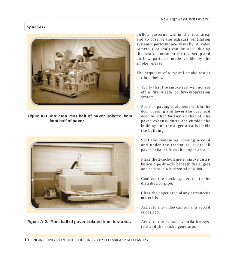
airflow patterns within the test area,and to observe the exhaust ventilationsystem’s performance visually. A videocamera (optional) can be used duringthis test to document the test setup andair-flow patterns made visible by thesmoke release.
The sequence of a typical smoke test isoutlined below:
• Verify that the smoke test will not setoff a fire alarm or fire-suppressionsystem.
• Position paving equipment within thedoor opening and lower the overheaddoor or other barrier so that all thepaver exhaust ducts are outside thebuilding and the auger area is insidethe building.
• Seal the remaining opening aroundand under the tractor to isolate allpaver exhaust from the auger area.
• Place the 2-inch-diameter smoke distri-bution pipe directly beneath the augersand secure in a horizontal position.
• Connect the smoke generator to thedistribution pipe.
• Clear the auger area of any extraneousmaterials.
• Activate the video camera if a recordis desired.
• Activate the exhaust ventilation sys-tem and the smoke generator.
Figure A-1. Test area rear half of paver isolated fromfront half of paver.
Figure A-2. Front half of paver isolated from test area.

ENGINEERING CONTROL GUIDELINES FOR HOT MIX ASPHALT PAVERS 11
• Inspect the separating barrier forintegrity failures and correct them asrequired.
• Inspect the exhaust ventilation sys-tem for unintended leaks at all fit-tings.
• Deactivate the exhaust ventilationsystem for a short time to simulate ano-control condition for comparisonpurposes.
• Deactivate the smoke generator andwait for smoke levels to subside. Youmay want to turn on additionalexhaust ventilation to clear the roommore quickly.
• Disassemble the test equipment (thesmoke generator may be HOT).
• Move the smoke generator outsideand introduce smoke into the enginecooling air intake. Observe the augerarea for signs of smoke leaking fromthe engine area into the auger area. Ifsmoke is observed in the auger area,corrections to the equipment designmay be needed. Engine-cooling airthat is blowing into the auger areawill make the ventilation system lesseffective in capturing asphalt fumes.
Tracer Gas Test
The tracer gas test is designed to (1) cal-culate the total exhaust flow rate of thepaver exhaust ventilation system and (2)
evaluate the system’s effectiveness incapturing and controlling a surrogatecontaminant under controlled indoorconditions. SF6 should be used as thesurrogate contaminant.
Calibrate the SF6 detector and themass-flow controllers before testingbegins. If the manufacturer of the detec-tor can provide a calibration curve for theSF6 concentration range of interest, atwo-point calibration check may besufficient. The two-point calibration con-sists of a 0-ppm SF6 point and a12-ppm SF6 point. Gas cylinders for eachcalibration point can be purchased. Fillindustrial hygiene sampling bags fromeach cylinder and hook each bag to thedetector; then record the response of thedetector for each concentration. Clearlymark each sample bag with the concen-tration of SF6 it contains. Bags can bereused; however, they should be emptiedbefore reuse, and they should be filledwith approximately the same concentra-tion of SF6. For example, a bag used tohold 12 ppm SF6 in a previous testshould not be used to hold the0-ppm SF6 air sample in the next test,since residual gas may cause an incorrectcalibration point. If the detector responseto the 0-ppm SF6 air sample is less than3 times the lower limit of detection, andif the detector response to the 12 ppmSF6 is within 7% of the detector calibra-tion curve at that point, proceed with thetesting. If the calibration checks are notwithin these specifications, determinethe source of the errors and correct thembefore proceeding.

Appendix
New Highway-Class Pavers
12 ENGINEERING CONTROL GUIDELINES FOR HOT MIX ASPHALT PAVERS
Calibrate the mass-flow controllerswith a bubble meter and a timer. Allowthe CP-grade SF6 to flow through thepressure regulator to the mass-flowcontrollers, which can regulate theflowrate as determined from Table 1.Direct the flow through the wet bubblemeter to determine the actual SF6flow rate (NIOSH [1973]. The IndustrialEnvironment — Its Evaluation andControl. Cincinnati, OH: U.S. Departmentof Health, Education, and Welfare,Public Health Service, Centers forDisease Control, National Institute forOccupational Safety and Health, p. 105).
The 100% Capture TestThe 100% capture test is achieved byreleasing a known rate of CP-grade SF6into the ventilation system, mixing the
air to obtain a uniform concentration,and sampling the concentration of SF6in the exhaust of the ventilation system.The accuracy with which the SF6 flowcontrollers are calibrated directlyaffects the accuracy of the test. All theSF6 must be released into the ventila-tion system and be thoroughly mixedbefore reaching the detector samplingpoint. Releasing the SF6 at two pointsjust inside the exhaust hood on eachside of the paver exhaust ventilationsystem will give the best chance forcomplete mixing. Connect the supplytank of CP-grade SF6 to the two releasepoints via a pressure regulator, twomass-flow controllers, and as much 1/4-inch-tubing as needed.
Find a downstream sampling loca-tion in the exhaust ventilation systemwhere the SF6 gas has been thoroughly
Total ventilation flow ratepredicted from ventilation
measurements(cubic feet/minute)
1,500
2,000
2,500
3,000
3,500
4,000
Total SF6 flow rate needed(liters/minute)
0.51
0.68
0.85
1.02
1.19
1.36
SF6 flow rate needed toeach side of the paver
(liters/minute)
0.25
0.34
0.42
0.51
0.59
0.68
Table 1. Flow Rate Determination

ENGINEERING CONTROL GUIDELINES FOR HOT MIX ASPHALT PAVERS 13
mixed so that a sample from that pointwill be representative of all gas in thesystem. Thorough mixing can beachieved by the fan that moves the air;thus if the sample is taken downstreamof the fan, it should be sufficientlymixed. However, if there are two fansand the air from each fan meets nearthe detector sampling point, the twostreams of air may not be thoroughlymixed by the time the gas reaches thesampling point. If the gases are notthoroughly mixed, an extension on theexhaust duct may be needed.
If the air is thoroughly mixed, placea 1/4-inch-diameter sampling hole inthe exhaust ventilation duct two-thirdsof the way between the base of theexhaust duct at the paver deck and thetop of the exhaust duct (closer to thetop). Insert the sampling probe into thehole perpendicular to the exhaust airflow. Position the holes in the samplingprobe inside the duct and perpendicularto the exhaust air flow. The 1/8-inch-diameter tubing should connect thesampling probe to the detector andshould be airtight to ensure that thesample is pulled from within theexhaust duct and not from the sur-rounding area. Take at least five mea-surements during a 3-minute periodand use the average concentration tocalculate the exhaust volume with thefollowing equation:
Q(SF6)Q(exh) = × 106
C *(SF6) Equation 1A
where
Q(exh) is the flow rate of air exhaustedthrough the ventilation system(liters/minute or cubic feet/minute)[to convert from liters/minute to cubicfeet/minute, divide liters/minute by28.3],
Q(SF6) is the flow rate of SF6(liters/minute or cubic feet/minute)introduced into the system, and
C*(SF6) is the concentration of SF6
(parts per million) detected in exhaustduring the 100% SF6 capture test.
Repeat the above procedure for eachduct if there is more than one exhaustventilation duct. Allow sufficient timebetween tests for the background read-ings to drop below 0.1 ppm SF6.Subtract background readings betweensequential tests from the detectorresponse before calculating the exhaustvolume.
Quantitative Capture Efficiency
PPosition the 1/2-inch-diameter cop-per distribution plenum underthe augers and orient the holes of
the plenum upward on center with theaugers. Connect the two 1/4-inch-diame-ter discharge tubes coming from the cal-ibrated flow controllers to the distribu-tion plenum with a tee connection.Release the SF6 at the same predeter-mined flow rate used in the 100% cap-ture test. The SF6 distribution plenumis designed to release the SF6 evenly

throughout the length of the auger area.This test uses the sampling probe, sam-pling location, and SF6 detector used inthe 100% capture test (See Figure A-3).
Take at least five measurementsduring a 3-minute period and calculatean average value. Calculate the captureefficiency using the following equation:
C(SF6)η = × 100
C *(SF6) Equation 2A
where
η is the capture efficiency,
C(SF6) is the concentration of SF6(parts per million) detected in exhaust,and
C*(SF6) is the concentration of SF6from the 100% capture test.
Perform a total of four pairs of the100% capture tests and capture efficiencytests and determine the overall captureefficiency of the ventilation system fromthe average of all four trials.
Shut down the paver between eachpair of tests (i.e., after one 100% capturetest and one capture efficiency test) tosignify the completion of the test.Monitor background SF6 measurementsto determine whether any SF6 has accu-mulated in the test area. If more than1.0 ppm SF6 has accumulated, check theintegrity of the barrier system and venti-late the test area well before proceeding.Allow sufficient time between tests for
Appendix
New Highway-Class Pavers
14 ENGINEERING CONTROL GUIDELINES FOR HOT MIX ASPHALT PAVERS
End Cap1/2” Copper
Distribution PlenumAuger Gear BoxSF6 Inlet Fitting
Slat Conveyor Tunnels
Figure A-3. Sample schematic for SF6 release and capture at the paver auger.

ENGINEERING CONTROL GUIDELINES FOR HOT MIX ASPHALT PAVERS 15
the background readings to drop below0.1 ppm of SF6. Subtract backgroundreadings from the detector responsebefore making calculations.
The sequence for a typical test run isoutlined below:
• Position paving equipment and sealopenings as outlined above. Performthe smoke test before conducting thetracer gas tests.
• Check the SF6 detector calibrationand record the two-point calibrationcheck and the ambient temperatureand pressure.
• Calibrate (exhaust to outdoors) themass flow meters to levels dictated byTable 1 using SF6.
• Drill an access hole in the exhaustventilation duct and insert the detec-tor’s sampling probe. Determinewhether the gas stream is thoroughlymixed.
• Start the paver engine and run at therpm that will be used during normalpaving operations. Start the exhaustventilation system and begin moni-toring for SF6 to determine back-ground levels.
• While maintaining the SF6 tanks out-doors or in a well-ventilated area, runthe discharge tubing from each massflow meter to well within the exhaust
hood on each side of the paver exhaustventilation system to create 100%capture conditions.
• Initiate the flow of SF6 through theflow meter and allow it to reachsteady-state (this step should takeonly a minute). Use a soapy watersolution to check for SF6 leaksthroughout the SF6 delivery system.
• Continue monitoring until five read-ings are recorded during at least 3minutes.
• Deactivate the flow of SF6.
• Remove quickly the discharge tubingto an outdoor location so that the SF6does not leak from the tubes andcause increased background levelsof SF6.
• End the 100% capture test (leave thetractor engine running).
• Initiate monitoring to establish back-ground interference until SF6 concen-tration drops below 0.1 ppm.
• Locate the copper distribution plenumunder the auger area and connect theends of both 1/4-inch discharge tubesfrom the mass flow meters to one endof the plenum with a tee connection.
• Check background concentration toensure that it is less than 0.1 ppm SF6.

Appendix
New Highway-Class Pavers
16 ENGINEERING CONTROL GUIDELINES FOR HOT MIX ASPHALT PAVERS
• Initiate the SF6 flow through themass flow meters and begin monitor-ing SF6 concentrations (approximatesteady-state conditions will beachieved in about 1 minute). Take atleast five readings during a 3-minuteperiod.
• Discontinue the SF6 flow and removethe distribution plenum and dis-charge tubing from the auger area toan outside location. If the distributionplenum is left in place, there may bea longer delay before continuing tothe next test.
• Continue monitoring to determinethe concentration of SF6 that escapedinto the test area. Discontinue moni-toring when the concentration of SF6is below 0.1 ppm.
• Turn off the ventilation system andpaver engine; calculate the captureefficiency.
• Repeat both tracer tests four times.
Example Test Runand Calculations
he paver was positioned, thebarrier was constructed, andsmoke was used to visually testthe system. Smoke was seencoming in the top of the over-
head door. The opening in the overheaddoor was sealed, and the smoke testrevealed no other leaks in the barrier orthe exhaust ventilation system. No visi-ble smoke was in the auger area whensmoke was released into the engine cool-ing air intake.
For simplicity, the SF6 detector wascalibrated and adjusted to read SF6directly in ppm. The two SF6 mass flowmeters were set for an exhaust ventila-tion system that should deliver 2,600cubic feet/minute. Using Table 1, thetwo mass flow meters were eachadjusted to 0.45 liters per minute, for atotal flow rate of 0.90 liters per minuteshown below:
T
Trial Total SF6 flow rate (liters/minute)number (half to each side of the paver)
1 0.903
2 0.908
3 0.899
4 0.900
The mean flow rate was [(0.903 + 0.908 + 0.899 + 0.900) /4)]= 0.903 liters/minute.

ENGINEERING CONTROL GUIDELINES FOR HOT MIX ASPHALT PAVERS 17
The sampling probe was placed in theexhaust ventilation duct, and backgroundsamples were registered by the detector.The 1/4-inch tubing (CP-grade SF6 outlet)
from the two flow meters was placedthrough the hood and into the exhaustduct (upstream of the fan), one on eachside of the paver. Readings were as follows:
Task
Background
Start SF6
End
Reading number
1
2
3
4
5
6
7
8
9
10
11
12
13
14
Detector reading(ppm SF6)
0.0051
0.0062
0.0048
0.0050
0.0066
0.0062
0.0058
6.3
14.0
13.8
13.9
13.7
13.8
13.9

Appendix
New Highway-Class Pavers
18 ENGINEERING CONTROL GUIDELINES FOR HOT MIX ASPHALT PAVERS
0.90328.3 0.0319 × 10⁶
Q(exh) = × 106 = = 2,305 cubic feet/minute13.85 – 0.0057 13.84
In this case, the background value was negligible, and the calculated exhaust venti-lation cfm was shown to be almost 300 cfm lower than the original estimate of 2,600 cfm.
The same mass flow meters and SF6 flow rates were used for the capture efficiencytest. The tubing was removed from the exhaust ventilation hood and connected to the10-foot distribution plenum. Readings were as follows:
Detector readingTask Reading number (ppm SF6)
Background 1 0.092
2 0.084
3 0.078
Start SF6 4 20.1
5 11.8
6 12.6
7 12.7
8 13.9
9 10.3
10 12.4
11 11.9
12 12.6
At least five consecutive measure-ments are needed; in this case, the lastsix data points were used (i.e., readingnumber 9-14). The eighth reading (6.3ppm) does not reflect steady-state andwas not used in determining the aver-age. The mean concentration of SF6 is13.85 ppm (the average of those six
points). The mean background value is0.0057 ppm. These values were used tocalculate the volumetric flow rate(Qexh) from Equation 1A. To change theSF6 flow rate to cfm, divide by 28.3. Tocorrect for background readings, sub-tract 0.0057 from the SF6 average con-centration.

ENGINEERING CONTROL GUIDELINES FOR HOT MIX ASPHALT PAVERS 19
At least five consecutive measure-ments are needed; in this case, the lasteight were used. The fourth reading(20.1 ppm) was high, which reflects theflow controller overshooting the setpoint during the startup of SF6 flow;this point was not used in determiningthe average. The mean concentration ofSF6 was 12.28 ppm; the average back-ground concentration was 0.0847 ppm.
From Equation 2A, the capture effi-ciency is calculated by dividing the aver-
age SF6 concentration obtained duringthe efficiency test (minus the back-ground) by the average SF6 concentra-tion obtained during the 100% capturetest (minus the background). This is dis-played as a percentage:
(12.28 – .0847) × 100 = 88.1%(13.85 – 0.0057)
This procedure was done four timeswith the following results:
Statistics
Calculate the capture efficiency average:
m = (88.1 + 94.7 + 86.6 + 86.9) /4 = 89.1%
Calculate the estimated standard deviation:
s = {[(88.1 – 89.1)2 + (94.7 – 89.1)2 + (86.6 – 89.1)2 + (86.9 – 89.1)2] / (4-1)}0.5
= {(1.0 + 31.4 + 6.3 + 4.8) / 3}0.5 = 3.8
Trial number
1
2
3
4
100% capture(ppm SF6)
13.84
13.67
13.74
13.93
Capture efficiency(ppm SF6)
12.20
12.95
11.90
12.11
Capture efficiency(%)
88.1
94.7
86.6
86.9

Appendix
New Highway-Class Pavers
20 ENGINEERING CONTROL GUIDELINES FOR HOT MIX ASPHALT PAVERS
If the number of trials, n, is differentfrom 4, then (n-1) is used in the denomi-nator of this calculation and the numer-ator is the sum of all n-squared differ-ences rather than just 4-squared differ-ences. Choose the number t (from theStudent’s t-distribution table at the 95thpercentile) from the following tablebased on the value of n:
t: 6.31 (n=2) 2.92 (n=3) 2.35 (n=4)2.13 (n=5) 2.02 (n=6) 1.94 (n=7)1.90 (n=8) 1.86 (n=9) 1.83 (n=10)
Calculate a test statistic (T):
(t × s)T = m – n0.5
For this example, the average meanvalue is m=89.1; the t-distribution valueis t=2.35; the standard deviation of themean values is s=3.8; and the samplesize is n=4:
If T > 80.0, it can be concluded with95% confidence that the efficiency of theexhaust ventilation is greater than 80%as tested in the laboratory. In this exam-ple, we are 95% confident that the effi-ciency is greater than 84.6%.
If T ≤ 80.0, the conclusion that theefficiency is greater than 80% cannot bemade from these data.
(2.35 × 3.8)T = 89.1 – = 89.1 – 4.5 = 84.640.5

ENGINEERING CONTROL GUIDELINES FOR HOT MIX ASPHALT PAVERS 21
Asphalt paver: A self-propelled constructionmachine (either rub-ber-tired or crawler-mounted) designed toreceive, convey, dis-tribute, profile, andcompact paving mate-rial by the free-float-ing screed method.There are two classesof paving equipment—highway-class paversand nonhighway- classpavers.
Auger: A screw conveyorused to distributepaving material trans-versely ahead of thescreed.
Conveyor: A device fortransferring pavingmaterial from the hop-per to the auger.
Conveyor flow gate: Adevice for regulatingthe height of paving
material being trans-ferred by the conveyor.
Highway-class pavers:Self-propelled paversweighing 16,000pounds or more thatare used principally toplace hot mix asphalton highways, roads,streets, and airports.
Hopper: The section ofthe paver thatreceives the pavingmaterial from anexternal source.
Nonhighway-classpavers: Pavers thatweigh less than 16,000pounds and are usedprincipally to placehot mix asphalt onlocal streets, parkinglots, driveways, andother small projects.
Operator: The personwhose primary func-tion is to control the
paver’s speed anddirection.
Screed: The devicetowed behind the trac-tor to strike off, com-pact, contour, andsmooth the pavingmaterial.
Screed end plate: Avertically adjustableplate located at theoutboard end of thescreed to retain thepaving material andform the edge of themat.
Tractor: The portion of apaver that providespropulsion and mayalso receive, convey,and distribute pavingmaterial.
Tunnel: The passagewaythrough which pavingmaterial moves fromthe hopper to theauger/screed.
Glossary of Terms


Delivering on the Nation’s promise:• Safety and health at work for all people
through research and prevention
DHHS (NIOSH) Publication No. 97-105