asme viii subsection a general requirements (ug) · pdf fileasme viii subsection a general...
TRANSCRIPT

ASME VIII
SUBSECTION A GENERAL REQUIREMENTS
(UG)
Prepared by: Eng. Mahmoud Elsayed E-mail: [email protected]

Contents Materials Pressure parts Non pressure parts Forging materials Casting materials Pipes and tubes Bolts Welding materials Design Shell design under internal pressure under external pressure Head design

Materials Materials for pressure parts like shell and heads shall conform
specifications in ASME SEC II D
Materials for non pressure parts like skirts,lugs,supports, fins,……. etc need not need not conform to the specifications for the material to which they are attached or to material specification permitted in this Division.
materials covered by specifications in section II is not restricted
by production method unless so stated in the specifications and as long as it complies with specs requirements

Materials Materials other than those allowed by this Division
may not be used, unless data thereon are submitted to and approved by the BPVC Committee in accordance with Appendix 5 in Section II, Part D.
Materials outside the limits of size and/or thickness
given in the title or scope clause of the specifications given in Section II, and permitted by the applicable part of Subsection C, may be used if the material is in compliance with the other requirements of the specification,1 and no size or thickness limitation is given in the stress tables.

Materials
Materials other than allowed by this division shall not be used unless it is approved from BPV committee
Materials outside the limits of size and thickness mentioned in ASME II and permitted by subsection C may be used if materials comply with other specs requirements and no thickness limitation given in stress tables

Materials
Forging materials may be used in pressure vessel construction provided that the material has been worked sufficiently.
Casting materials may be used in construction of pressure vessels. material allowable stress should be calculated as per UG 23 multiplied by casting factor from UG 24

Materials
Pipes and tubes of seamless or welded shall be used for shells and other pressure parts of pressure parts , max allowable stress for such shall be determined according to UG 23

Materials
Tubes after finning should be tempered Max allowable stress should be calculated as per UG 23 MAWP shall be determined based on the root thickness of finned
thickness or the thickness of unfined section which ever results in lower MAWP
In addition to the above and specs requirements as per sec II finned tubes shall be subjected to pneumatics and hydrostatic test as per the following requirements
Finned tubes may be used as shell of pressure vessels or other pressure parts in case of :
Pneumatic test of not less than 1.7 MPA for %sec without evidence of leakage
Hydrostatic tests according to UG 99

Materials
Welding materials used for production should comply with ASME II C and ASME IX requirements

Materials Bolts and studs may be used for the attachment of removable
parts. Specifications, and maximum allowable stress values for acceptable bolting materials are given in the tables referenced in UG-23.
Studs shall be threaded full length or shall be machined down to the root diameter of the thread in the unthreaded portion, provided that the threaded portions are at least 11⁄2 diameters in length.

DESIGN
Before introducing the design equations and procedure we should define first some main parameters that used in design, this parameters can be summarized as follows:
Design temperature Design pressure Loading Maximum allowable stress of material

Design temperature When we say design temperature we should consider
two values of temperatures Maximum temperature that is because higher temperature affect on the
strength of material the higher the temperature the lower the strength
Minimum temperature that is because low temperature negatively affect on
the toughness of the material

Design temperature
Maximum temperature •The maximum temperature used in design shall be not less than the mean metal temperature (through the thickness) under operating conditions
•If it necessary mean metal temperature may be determined through computation or measurement from equipment under equivalent conditions in service
•Design temperatures that exceed the temperature limit in ASME SEC II are not permitted
•design temperatures for vessels under external pressure shall not exceed the maximum temperatures given on the external pressure charts

Design temperature
Minimum temperature •The minimum temperature used in design shall be the lowest expected temperature during service, taking in consideration lowest operating temperature, operational upsets, auto refrigeration, atmospheric temperature, and any other sources of cooling
•MDMT corresponds to MAWP should be mentioned on the vessel Nameplate
•Impact test requirements should be as per UCS 66

Design pressure
Design pressure shall meet the most severe pressure that the vessel will be subjected to while being in service.

Loading Different loadings should be considered through the design of pressure
vessels like : internal or external design pressure weight of the vessel reactions from weight of attached equipment, such as motors,
machinery………… the attachment of: (1) internals (2) vessel supports, such as lugs, rings, skirts, saddles, cyclic and dynamic reactions due to pressure or thermal variations wind, snow, and seismic reactions impact reactions such as those due to fluid shock temperature gradients abnormal pressures test pressure

Maximum allowable stress (UG 23)
The maximum allowable stress value is the maximum unit stress permitted in a given material used in a vessel constructed under these rules. The maximum allowable tensile stress values permitted for different materials are given in ASME Section II, Part D.
Part Application UCS 23 Carbon steel UHA 23 High alloy steel UCI 23 Cast iron UHT 23 Heat treated ferritic steel

Design
The wall thickness of a vessel computed by these rules shall be determined such that, for any combination of loadings listed in UG-22 that induce primary stress and are expected to occur simultaneously during normal operation of the vessel, the induced maximum general primary membrane stress does not exceed the maximum allowable stress value in tension

Design
Before introducing the formulas that govern design of pressure vessel , we should talk a look of pressure vessels parts which are designed

Design Pressure vessel mainly consists of: 1. Shell 2. Heads 3. Nozzles 4. Supports(saddles,skirts,lugs) For each of the previous we will introduce the governing equations for design
according to ASME VIII DIV 1

2-Shell design

1-Shell Shell of pressure vessel is designed based on the pressure that it is subjected to either internal or pressure Shell design can be classified according to ASME VIII into two categories.
1-Shell subjected to internal pressure
2-Shell subjected to external pressure

1-Shell
a-Shell subjected to internal pressure

1-Shell Under internal pressure
Under internal pressure For the vessels subjected to internal pressure
thickness should be the greater thickness from the following equations.

1-Shell Under internal pressure
P internal design pressure R vessel inside radius S allowable stress of material
E Joint efficiency (UW 12) t Minimum required thickness of shell

1-Shell
b-Shell subjected to external pressure

1-Shell Under external pressure
Criteria of designing vessels under external pressure is slightly different from the criteria used in internal pressure design.
the next section we will introduce the procedure according to ASME VIII but before introducing it some parameters should be defined first

1-Shell Under external pressure
P external design pressure
Ro Vessel outside radius
Do Vessel outside diameter
E Joint efficiency (UW 12)
A,B Factors determined from ASME SEC II
t Minimum required thickness of shell
L Design length

1-Shell Under external pressure
Designed length is determined according to the following figure which depends on the geometry of the vessel

D/t 10 Inputs D,P,L Assume t
Calc L/D,D/t
Get value A (ASME II D)
Enter material charts in ASME II to get value B
Pa>P
start
finish
yes
No
No
Yes
Next slide

D/t >4
Get value A (ASME II D)
Enter material charts in ASME II to get value B
finish
yes
No
Pa=min(Pa1,Pa2)
Pa>P yes No Repeat all steps from
assuming t
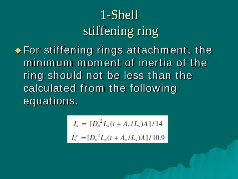
1-Shell stiffening ring
For stiffening rings attachment, the minimum moment of inertia of the ring should not be less than the calculated from the following equations.
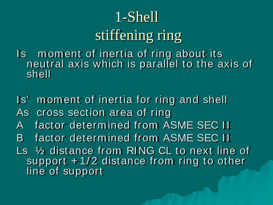
1-Shell stiffening ring
Is moment of inertia of ring about its neutral axis which is parallel to the axis of shell
Is’ moment of inertia for ring and shell As cross section area of ring A factor determined from ASME SEC II B factor determined from ASME SEC II Ls ½ distance from RING CL to next line of
support +1/2 distance from ring to other line of support

2- Head design

2-head
For Ellipsoidal heads
The minimum required thickness for head can be calculated from the following formula:

2-head
For torispherical heads
The minimum required thickness for head can be calculated from the following formula:

2-head
For hemispherical heads
The minimum required thickness for head can be calculated from the following formula:

2-head
For conical heads
The minimum required thickness for head can be calculated from the following formula: