asian development bank - national capital region …ncrpb.nic.in/ncrbp adb-ta...
TRANSCRIPT

NCR Planning Board Asian Development Bank
Capacity Development of the National Capital Region Planning Board (NCRPB) – Component B (TA No. 7055-IND)
FINAL REPORT Volume V-D1: DPR for Multi-level Parking Facility at Ghaziabad Main Report
July 2010
i
Abbreviations
ADB Asian Development Bank BIS Bureau of Indian Standard BOQ Bill of Quantities CBR California Bearing Ratio CMSA Cumulative number of Million Standard Axles DFR Draft Final Report DL Deal Load DPR Detailed Project Report ECS Equivalent Car Space GDA Ghaziabad Development Authority INR Indian Rupees IRC Indian Road Congress IS Indian Standard KMPH Kilometer per Hour LCV Light Commercial Vehicle LL Live Load MAV Multi-axle Vehicle MORT&H Ministry of Road Transport and Highways NCR National Capital Region NCRPB National Capital Region Planning Board NH National Highway RCC Reinforced Cement Concrete ROW Right of Way SP Standard Procedure TA Technical Assistance UP Uttar Pradesh UPSRTC Uttar Pradesh State Road Transport Corporation
ii
Contents
1. INTRODUCTION ....................................................................................................................................... 1
A. BACKGROUND ............................................................................................................................................ 1 B. OVERVIEW OF THIS ADB TA ..................................................................................................................... 2 C. ABOUT THE FINAL REPORT ........................................................................................................................ 3 D. STRUCTURE OF VOLUME V REPORT ........................................................................................................... 4
1. Structure of this Volume V-D Report .................................................................................................... 4
2. PARKING DEMAND ANALYSIS ............................................................................................................. 5
A. OVERVIEW ................................................................................................................................................. 5 B. EXISTING PARKING SCENARIO ................................................................................................................... 5 C. PARKING DEMAND ANALYSIS .................................................................................................................... 8
1. On Street Survey .................................................................................................................................... 9 2. Willingness to Pay Survey ................................................................................................................... 11 3. Survey Schedule .................................................................................................................................. 11
D. PARKING ANALYSIS AND FINDINGS .......................................................................................................... 12 1. Roadway Inventory (Carriage way and ROW) and Issues at the proposed site for parking. .............. 12 2. Parking Supply .................................................................................................................................... 12 3. Survey Findings ................................................................................................................................... 16
E. PARKING DEMAND FORECAST .................................................................................................................. 16 1. Parking Demand Forecast .................................................................................................................. 16 2. Space Requirement .............................................................................................................................. 17
F. RECOMMENDATIONS ................................................................................................................................ 18 G. DESCRIPTION OF THE PROPOSED PARKING SITE (OLD BUS STAND) ........................................................... 18
1. Access roads to site ............................................................................................................................. 18 H. PROPOSED MULTISTORY PARKING FACILITY & TRAFFIC CONSIDERATIONS ............................................ 21
3. PLANNING & DESIGN OF MULTI-LEVEL PARKING FACILITY ................................................ 22
A. GENERAL ................................................................................................................................................. 22 B. SURVEYS & INVESTIGATIONS ................................................................................................................... 22
1. Topographical Survey ......................................................................................................................... 22 C. PLANNING CONSIDERATIONS ................................................................................................................... 23 D. STRUCTURAL SYSTEM .............................................................................................................................. 27 E. ANALYSIS OF THE MULTILEVEL PARKING ................................................................................................ 30
4. COST ESTIMATES .................................................................................................................................. 32
A. RATE ANALYSIS ....................................................................................................................................... 32 B. BILL OF QUANTITIES & COST ESTIMATES ................................................................................................ 32
List of Tables
Table 2-1: Codes adopted for various types ........................................................................................... 9 Table 2-2: ECS Values adopted for Various Vehicle Types ................................................................ 10 Table 2-3: Classification of Duration of Parking ................................................................................. 10 Table 2-4: Schedule of Surveys ........................................................................................................... 11 Table 2-5: Parking Demand for 16 hours –On Street (ECS) Cars and Two wheelers ......................... 13 Table 2-6: Parking Demand for Peak Hour –On Street (ECS) Cars and Two wheelers ...................... 13 Table 2-7: Peak hour Parking Demand, Parking Supply and Gap – On Street (ECS) Cars and Two
wheelers ........................................................................................................................................ 13 Table 2-8: Details of Trip Purpose ....................................................................................................... 16 Table 2-9: Details of Trip Frequency ................................................................................................... 16 Table 2-10: Parking demand is projected to 2030 ................................................................................ 17 Table 3-1: Particulars of Proposed Multi-level Parking Facility .......................................................... 24

iii
List of Figures
Figure 2-1: On-street and Off-street Parking in the Study Area ............................................................ 7 Figure 2-2: Average Hourly variation of parking Accumulation in zone 1 ......................................... 14 Figure 2-3: Average Hourly variation of parking Accumulation in zone 2 ......................................... 14 Figure 2-4: Average Hourly variation of parking Accumulation in zone 3 ......................................... 15 Figure 2-5: Average Hourly variation of parking Accumulation in zone 4 ......................................... 15 Figure 2-6: Average Hourly variation of parking Accumulation at Ambedkar Veedhi ....................... 15 Figure 2-7: Road network around the proposed Parking Lot ............................................................... 18 Figure 2-8: Existing Entry and Exist Details at Old Bus Stand ........................................................... 20 Figure 3-1: Ground Floor Plan of the Proposed Multilevel Parking .................................................... 25 Figure 3-2: Typical Floor Plan of the Proposed Multilevel Parking Facility ....................................... 26
List of Appendices
Appendix 1: Architectural Drawings Appendix 2: STAAD Model Appendix 3: STAAD Input File Appendix 4: Design of Footing Appendix 5: Design of Columns Appendix 6: Design of Beams Appendix 7: Design of Slab Appendix 8: Structural Drawings Appendix 9: BOQs and Detailed Quantity Estimates Compendium Volumes Besides this Volume V-D1, the DPR Multi-Level Parking in Ghaziabad has following Volumes appended separately. Volume V-D2: Financial & Economic Analysis Volume V-D3: Initial Environmental Examination Volume V-D4: Short Resettlement Plan

WSA_NCRPB_FR MLPGZB (15 Jul 10)
1
1. INTRODUCTION
A. Background 1. The National Capital Region Planning Board, constituted in 1985 under the provisions of
NCRPB Act, 1985, is a statutory body functioning under the Ministry of Urban Development, Government of India. NCRPB has a mandate to systematically develop the National Capital Region (NCR) of India. It is one of the functions of the Board to arrange and oversee the financing of selected development projects in the NCR through Central and State Plan funds and other sources of revenue.
2. On Government of India’s request, Asian Development Bank (ADB) has formulated the
technical assistance (TA) to enhance the capacities of National Capital Region Planning Board and its associated implementing agencies. The TA has been designed in three components: Component A relates to improving the business processes in NCRPB; Component B relates to improving the capacity of the implementing agencies in project identification, feasibility studies and preparing detailed engineering design; and Component C relates to urban planning and other activities.
3. ADB has appointed M/s Wilbur Smith Associates to perform consultancy services
envisaged under Component B. In the context of this contract, the first deliverable – Inception Report, was submitted in October 2008. The second deliverable –Interim Report comprising Master Plan for sewerage in Hapur, Master Plan for Water Supply for Panipat, Master Plan for Drainage for Hapur, Master Plan for Solid Waste management for Ghaziabad, Traffic and Transport analysis for Ghaziabad, Socio-Economic base line survey result in 3 sample project towns and proceedings of workshop 1 was submitted in January 2009. The four Master Plans as stated above are also made available on NCRPB web site for use of the implementing agencies.
4. The third deliverable Draft Final Report (DFR) comprising Detailed Project Report (DPR)
for water supply in Panipat, DPR for sewerage in Hapur, DPR for drainage in Hapur, DPR for drainage in Sonipat, DPR for solid waste management in Ghaziabad, DPR for four selected transport components (Flyover, Road widening, Multi-level Parking and Bus Terminal) in Ghaziabad, and a Report on Capacity Building Activities were submitted.
5. Now, this is the Final Report (FR) and is the fourth and final deliverable. The
comments/feedback on Draft Final Report received from ADB, NCRPB and respective implementing agencies were duly incorporated and final DPRs for components of Water Supply, Sewerage, Drainage, Solid Waste Management, and Transport are submitted as part of this Final Report. This is the Detailed Project Report for Transport Component of Multi-level Parking in Ghaziabad.

WSA_NCRPB_FR MLPGZB (15 Jul 10)
2
B. Overview of this ADB TA 6. Objectives. The objective of this TA is to strengthen the capacity at NCRPB, state-level
NCR cells, and other implementing agencies in the area of planning for urban infrastructure and to impart necessary skills to conceive, design, develop, appraise and implement good quality infrastructure projects for planned development of NCR. The increased institutional capacity of the NCRPB and the implementing agencies will lead to effective and time scaling-up of urban infrastructure to (i) improve quality of basic urban services in the NCR; (ii) develop counter magnet towns; (iii) reduce in migration into Delhi and orderly development of NCR; and (iv) accelerate economic growth in the NCR.
7. The TA – Capacity Development of the NCRPB, Component B focuses on strengthening
the capacities of NCRPB and implementing agencies relating to project feasibility studies and preparation, and detailed engineering design in the implementing agencies. Specifically this component B of the TA will support the project preparation efforts of the implementing agencies by preparing demonstration feasibility studies that include all due diligence documentation required for processing of the project in accordance with best practices, including ADB’s policies and guidelines.
8. Scope of Work. According to the terms of reference of the TA assignment, the following
activities are envisaged in component B of the TA: (i) Conduct technical, institutional, economic and financial feasibility analysis of
identified subprojects in the six sample implementing agencies; (ii) Conduct safeguards due diligence on the subprojects, including environmental
assessment report and resettlement plan for all subprojects covered in the sample implementing agencies;
(iii) Prepare environmental assessment framework and resettlement framework; and (iv) Develop a capacity building and policy reform program for the implementing
agencies, including governance strengthening, institutional development and financial management.
9. Besides, this component of the TA will also:
(i) help in assessing the current practices and procedures of project identification and
preparation of detailed project reports including technical, financial, economic and social safeguard due diligence;
(ii) support preparation of standard procedure manuals for project identification and preparation of detailed project reports including technical, financial, economic and social safeguard due diligence;
(iii) train the implementing agencies in the preparation of detailed project reports by using the sample subprojects, reports on deficiency of current practices and standard protocol manuals; and
(iv) help in developing a user-friendly web-page where different manuals and guidelines for preparation of DPRs will be made available for the implementing agencies.

WSA_NCRPB_FR MLPGZB (15 Jul 10)
3
C. About the Final Report 10. At Interim Report stage of the TA, the Master Plans for Water Supply in Panipat,
Sewerage system in Hapur, Drainage for Hapur and Municipal Solid Waste Management for Ghaziabad were prepared. The Master Plans provided 100 percent coverage of population and the area likely to be in planning horizon year 2031/2041. All works required up to planning horizon year were conceptualized, broadly designed and block cost was estimated. The Master Plans also provided phasing of investment such that under phase 1 works required to cover present spread of city were proposed.
11. At draft final report stage of the TA the Detailed Project Reports (DPRs) were prepared
for Phase 1 works as suggested in the Master Plans. For preparation of DPRs, engineering surveys and investigations were conducted and various possible and feasible alternatives evaluated. Finally for the selected options the DPRs prepared with detailed designs, item wise detailed cost estimate, work specifications, implementation process and proposed implementation arrangements. Further, according to ADB procedures these DPRs in addition to technical analysis included institutional, financial and economic feasibility analysis and environmental and social safeguards due diligence – environmental assessment and resettlement plans.
12. The DPR's submitted as part of Draft Final Report was reviewed by the implementing
agencies, NCRPB and the ADB. Now this Final Report comprising DPR's modified in light of comments of IA's is being submitted. The draft DPR for water supply in Panipat was reviewed by PHED Haryana. Detailed discussions were held with Superintending Engineer (Urban), Executive Engineer (Urban), Superintending Engineer (Karnal) and Executive Engineer Panipat. The comments made by PHED have been suitably incorporated in this Final Report.
13. These DPRs are proposed to be made available to the ULBs and other implementing
agencies of the state governments as model DPRs so that they may replicate the methodology/approach in the future DPRs prepared by them for obtaining finances from the NCRPB.
14. Organization of this Final Report. The Final Report of the TA Component B is organized
in following Seven Volumes:
Volume I: Detailed Project Report for Water Supply System in Panipat Volume II: Detailed Project Report for Rehabilitation and Augmentation of
Sewerage System in Hapur Volume III: Detailed Project Report for Rehabilitation of Major Drains in Hapur Volume IV: Detailed Project Report for Improvement of Solid Waste Management
System in Ghaziabad Volume V: Detailed Project Reports for Four Transport Components in Ghaziabad Volume VI: Capacity Building Activities

WSA_NCRPB_FR MLPGZB (15 Jul 10)
4
Volume VII: Detailed Project Reports Rehabilitation of Drainage in Sonipat
D. Structure of Volume V Report 15. The DPRs for all four transport components are compiled in Volume V. This is Volume V
is presented four volumes: (i) Volume V-A: DPR for Mohan Nagar Flyover (ii) Volume V-B: DPR for Road Widening (iii) Volume V-C: DPR for Bus Terminal (iv) Volume V-D: DPR for Multi-level Parking
1. Structure of this Volume V-D Report 16. This DPR for Multi-level Parking Facility in Ghaziabad is compiled in following four sub-
volumes (Volumes V-D1 to V-D4) including this Main Report: Volume V-D1: Main Report:
• Section 1 Introduction • Section 2 presents parking demand analysis • Section 3 presents planning and design of the proposed parking facility • Section 4 presents cost estimates
Volume V-D2: Financial & Economic Analysis Volume V-D3: Initial Environmental Examination Volume V-D4: Short Resettlement Plan

WSA_NCRPB_FR MLPGZB (15 Jul 10)
5
2. PARKING DEMAND ANALYSIS
A. Overview 17. The unprecedented growth of personalized vehicles and the unplanned road infrastructure
have made the provision for parking an important aspect of transportation planning. As part of Traffic Study conducted as part of this ADB TA, a parking study was also conducted at important locations in Ghaziabad. The area surrounding the old Bus Stand at Navyug Market is major centre and is CBD of Ghaziabad. This centre is busy with various activities; a number of commercial establishments, markets, government offices (Ghaziabad Nagar Nigam and Ghaziabad Development Authority) and the bus stand are situated here. Since most of these places are frequented by public and busy with floating population, the demand for parking is very high.
17. On-street parking is observed on all the roads surrounding Old Bus Stand and Navyug
Market. Many cars and two wheelers are seen parked on either side of the roads. Both angular as well as parallel type of parking was noticed on almost all the stretches of the roads. This has reduced the capacity of the carriageway and endangering pedestrians and motorists alike. The frontage of almost all the roads in this area has been converted into commercial land use without taking into account the demand for parking of the vehicles. There is no planned parking space available.
18. Following sections assess the parking situation in the CBD area, its demand and the supply
analysis.
B. Existing Parking Scenario 19. At present, the vicinity of the old bus stand has developed in to a business and commercial
hub along with government offices and restaurants. Thus, the demand for the parking has increased leading to parking irregularities. On-street parking is observed on all the roads surrounding Old Bus Stand and Navyug Market which is adjacent to Ghaziabad Development Authority. Many cars and two wheelers are seen parked on either side of the roads. Both angular as well as parallel type of parking can be noticed on almost all the stretches of the roads. Consequently, almost one lane of the carriageway is taken up, in turn creating traffic chaos.
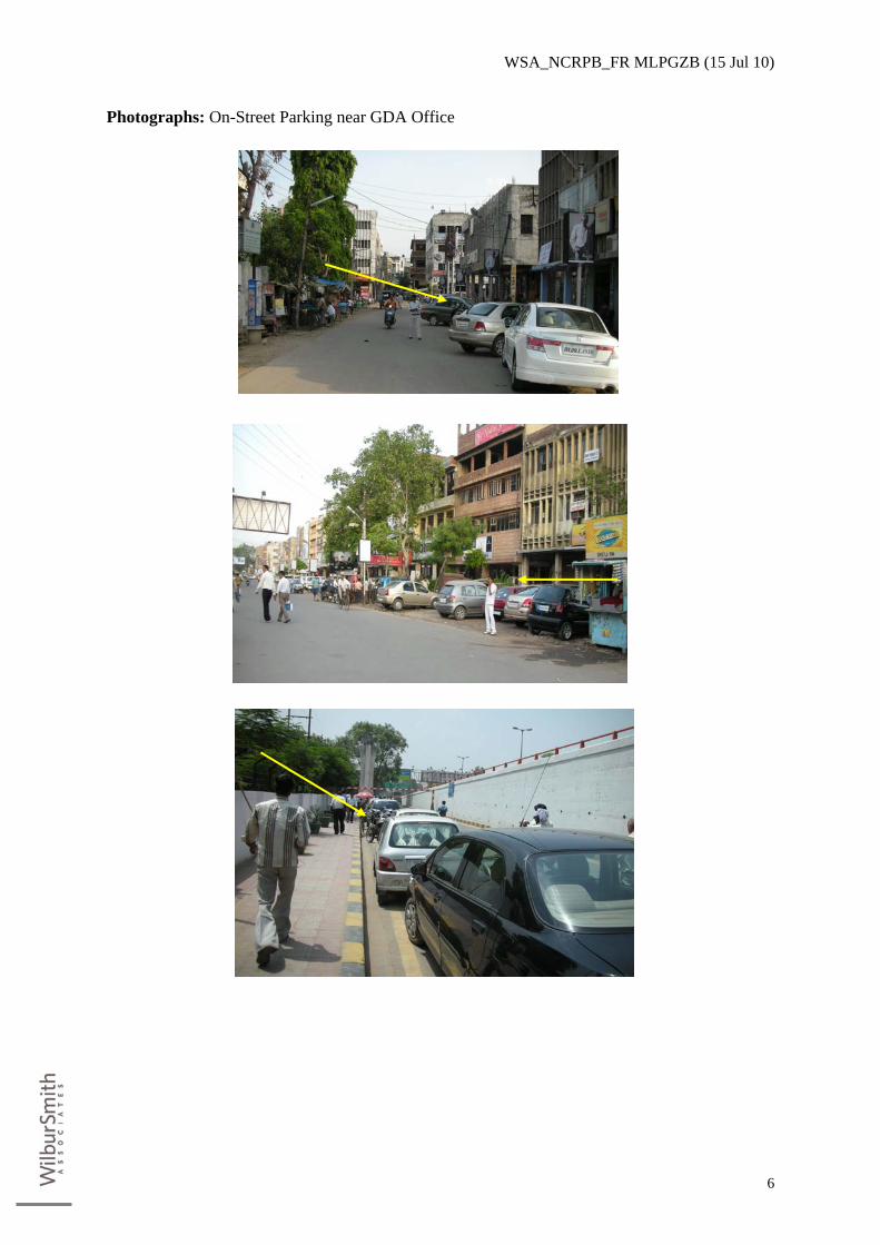
20. Following Photographs show the on-street parking scenario in CBD Area near GDA office
and Figure 2-1 show the location of existing parking places.
WSA_NCRPB_FR MLPGZB (15 Jul 10)
6
Photographs: On-Street Parking near GDA Office

WSA_NCRPB_FR MLPGZB (15 Jul 10)
7
Figure 2-1: On-street and Off-street Parking in the Study Area

WSA_NCRPB_FR MLPGZB (15 Jul 10)
8
C. Parking Demand Analysis 21. The following steps are involved in the parking study for Ghaziabad CBD area:
• Site reconnaissance • Conduct of Parking and Traffic Surveys • Estimation of current parking supply and demand • Future demand forecast • Development of conceptual parking facility layout
22. The following sections illustrate the approach and methodology, which have been
followed to undertake the study. Before the betterment of parking problems, it is necessary to analyze the existing parking characteristics at various locations. Parking surveys are intended to provide all the information needed for assessment of the parking demand and supply for the study area. All the survey formats are included in Annexure I.
23. Site Reconnaissance Survey. In order to understand the study, a site reconnaissance survey
is essential. This survey was done for the study area, to capture the road characteristics like available ROW and carriageway width. Land use in the site vicinity was also ascertained. Major establishments and traffic generators were identified. Traffic circulation and accessibility to the site were also assessed. Based on the above surveys, major issues in the area were identified.
24. Parking Surveys. The following surveys were conducted for understanding the parking
characteristics, estimation of demand and supply for parking and for projecting the future parking demand.
• On-street parking surveys to study the parking characteristics and demand along
the roadside. • Opinion surveys (willingness to pay surveys) elicited opinion of the users about
the facilities available for parking and their willingness to pay the fee for using the facility. The opinion survey also revealed the extent of suppressed parking demand.
• Inventory surveys were conducted to collect the potential of the existing facility in terms of available space, road characteristics, type of parking, land use of the location, etc.
25. Existing parking demand has been estimated through aggregation of on-street and off-
street parking surveys. After the reconnaissance survey, the study area layout map was prepared on which the road stretches and off street parking lots within 500m (walk distance) from the proposed locations were identified for parking surveys. The roads for survey were identified based on the intensity of parking on the selected stretches, and also their connectivity to the proposed site.

WSA_NCRPB_FR MLPGZB (15 Jul 10)
9
1. On Street Survey 26. On street parking surveys are intended to collect the extent of usage of parking facilities
along the roadside. The survey has been conducted by counting the vehicles parked on the road at regular intervals for a particular duration of the day.
27. The locations for the on-street survey have been identified through reconnaissance survey.
The survey was conducted to ascertain the characteristics and magnitude of parking and accumulation on the adjoining streets of the proposed parking. The proposed site and about 500 m around proposed parking were surveyed for on-street parking survey. Registration numbers of the parked vehicles were noted down at half an hour interval in major Parking areas. The survey was conducted from 8AM to 10 PM for three weekdays. The data collected include the time, type and registration number of the vehicle. Parking pattern of unregistered vehicles (like cycles, cycle rickshaws, etc.) was also estimated by counting such type of vehicles parked along the selected locations.
28. The data were entered in the format with the codes for each vehicle type. The codes
adopted for various vehicle types are given in Table 2-1.
Table 2-1: Codes adopted for various types S. No. Vehicle Category Code
1 Big Car bc 2 Small Car sc 3 Two Wheelers tw 4 Van v 5 Jeep j 6 Bus b 7 Trucks t 8 MAV mAV 9 LCV lCV 10 Auto Rickshaw aR
29. The data has been analyzed and the results are presented in terms of accumulation graphs
and duration diagrams. Different Equivalent Car Spaces (ECS) values were adopted for different vehicle types and are given in Table 2-2. The ECS values were arrived based on the size of various vehicles and compared with that of passenger cars. The duration of vehicles parked was classified into three categories and is given in Table 2-3.

WSA_NCRPB_FR MLPGZB (15 Jul 10)
10
Table 2-2: ECS Values adopted for Various Vehicle Types S. No. Vehicle Category ECS 1 Car 1.0 2 Two Wheelers 0.25* 3 Bus 2.5 4 Trucks 2.5 5 LCV 1.75 6 Auto 0.5 7 Cycles 0.1 8 Cycle Rickshaw 0.8 9 Carts 3.2
Source: Parking Requirements in CMA, 2003, Wilbur Smith Pvt Ltd
*Source: Module 4-Guidelines for Parking Measures-Policy and Options, MOUD and PADECO Co. Ltd
Table 2-3: Classification of Duration of Parking
30. Some important terms associated with parking are explained below:
(i) Parking Accumulation- Total number of vehicles parked in an area at a particular time period.
(ii) Parking Duration- Length of time a vehicle spent in a parking space (iii) Parking Occupancy- Number of spaces occupied as a percent of total available
spaces. (iv) Parking Turnover-It is usually calculated as the number of time a parking space is
been used during the day. Since there are no parking space demarcated in the study areas, and observed parking does not follow any parking norms, the parking turnover for the study is calculated per zone per ECS.
31. Outcome of the surveys include estimates of on-street parking volume, duration and
accumulation along each designated roadway stretch.
SL. No. Duration of Parking Designation of Parking 1 < 1 Hr Very Short Duration 2 1-2 Hours Short Duration 3 2-5 Hours Medium Duration 4 5-10 Hours Long Duration 5 > 10 Hours Long Term Parking

WSA_NCRPB_FR MLPGZB (15 Jul 10)
11
2. Willingness to Pay Survey 32. Opinion surveys were conducted to elicit the opinion of the parkers about the facilities
available for parking and about their willingness to pay the fee for using the proposed facility. The survey was done on a random sample basis during peak and off- peak periods. Users of the parking lot were interviewed and responses elicited include problems in existing parking facility, origin, destination, distance traveled, frequency of the visit, purpose of the visit, parking duration, occupancy, opinion about the existing parking rate with respect to existing facility, opinion about the parking fee system and willingness to pay. This survey was conducted on both weekdays and weekends.
33. A total of 522 samples were collected which comprised of 260 samples from Car users and
262 samples from non car users. Outcome of the survey includes identification of influence area of the market, frequency of the visit, purpose of the visit, problems with existing parking facility, occupancy rate opinion about the existing parking rate and about the future parking charge system with improved parking facility.
3. Survey Schedule
34. Parking surveys are conducted in the third and fourth weeks of August 2009. Detailed
schedule of all surveys is presented in the following Table 2-4.
Table 2-4: Schedule of Surveys
Type Schedule Date Day
Junction Volume Count 17-08-09 Monday Junction Volume Count 18-08-09 Tuesday Junction Volume Count 19-10-08 Wednesday
Type Schedule Date Day
Parking Accumulation Survey 20-08-09 Thursday Parking Accumulation Survey 21-08-09 Friday Parking Accumulation Survey 24-08-09 Monday Parking Accumulation Survey 25-08-09 Tuesday Parking Accumulation Survey 26-08-09 Wednesday Parking Accumulation Survey 27-08-09 Thursday Parking Accumulation Survey 28-08-09 Friday
Type Schedule Date Day
Opinion Survey 20-08-09 Thursday Opinion Survey 21-08-09 Friday Opinion Survey 24-08-09 Monday
WSA_NCRPB_FR MLPGZB (15 Jul 10)
12
D. Parking Analysis and Findings
1. Roadway Inventory (Carriage way and ROW) and Issues at the proposed site for parking.
35. The roadway details near the site are as follows:
• Dr Ambedkar Marg, the section leading the main entry to the site, is a four-lane divided roadway (2 lanes in each direction) with ~21 meter width.
• The right of entry to the site has no issues because the road width is sufficient enough to accommodate the entry –exit ramps.
• The roads covering the site have the width of about 7 meters on service lane of the Hapur Road on the northern side of the old bus stand and about 10 m on the cross road on the southern side of the old Bus Stand Road respectively.
• All the roads at the vicinity of the site are two way roads.
36. Major issues near the site are as follows:
• An existing off street paid parking lot near Ghaziabad Development Authority next to the old bus stand cannot cater to the parking demand in the area.
• Public tend to park on street (parallel parking) on the service lane adjacent to old bus stand near the GDA causing inconvenience to the traffic which takes almost one lane from the existing 7m width of the road.
• Unauthorized parking and vehicle waiting in front of Ghaziabad Development Authority and Nagar Nigam cause a lot of confusion and create bottleneck for the turning vehicles.
• Unauthorized Parking near Ghaziabad Development Authority and Nagar Nigam uses up the capacity of the roadway, thus affecting the flow of traffic. Parking needs to be prohibited in this area.
• Parking of auto rickshaws and cycle rickshaws is haphazard in front of the bus stand, where the entry and exit are at the same point. This causes queuing and traffic bottlenecks in this area.
2. Parking Supply
37. Two types of on street parking - parallel, and angular are prevailing in the study area. On
street parking includes vehicles parked on the street. There may be authorized parking stretches, as well as stretches where parking is prohibited, but still parking is observed. Majority of the on-street and off-street are unauthorized free parking. On street supply is estimated based on the number of authorized parking slots on a given stretch by maintaining the present configuration and availability of adequate right of way. Parking
WSA_NCRPB_FR MLPGZB (15 Jul 10)
13
supply is calculated as per the equivalent car space norms and available width of the right of way. For parallel and perpendicular parking, supply is calculated by dividing the length of the stretch by 7.5 m and 4 m respectively.
38. Total parking supply is calculated for the whole area based on the method mentioned
above. Parking Inventory of all the roads surveyed in the study area is given in Annexure II.
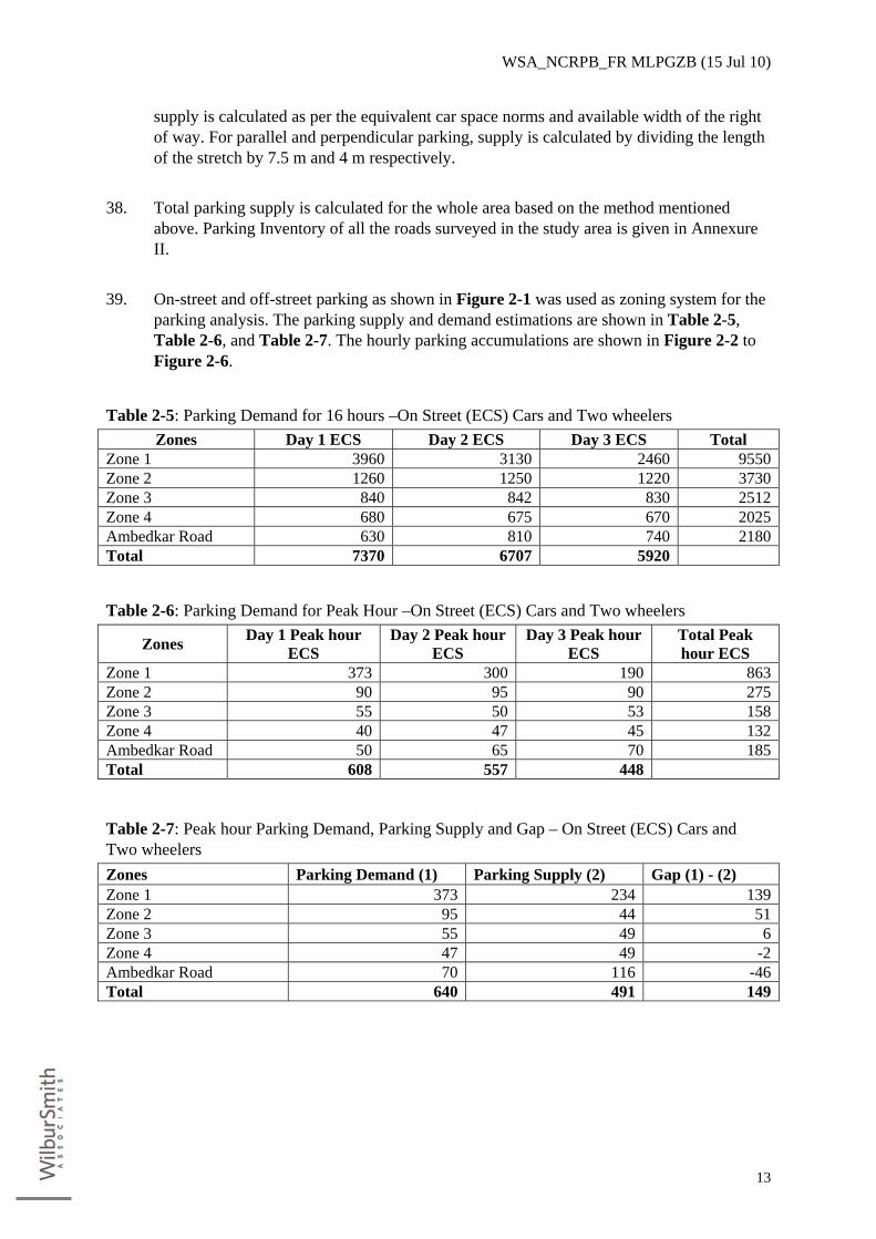
39. On-street and off-street parking as shown in Figure 2-1 was used as zoning system for the
parking analysis. The parking supply and demand estimations are shown in Table 2-5, Table 2-6, and Table 2-7. The hourly parking accumulations are shown in Figure 2-2 to Figure 2-6.
Table 2-5: Parking Demand for 16 hours –On Street (ECS) Cars and Two wheelers Zones Day 1 ECS Day 2 ECS Day 3 ECS Total
Zone 1 3960 3130 2460 9550Zone 2 1260 1250 1220 3730Zone 3 840 842 830 2512Zone 4 680 675 670 2025Ambedkar Road 630 810 740 2180Total 7370 6707 5920
Table 2-6: Parking Demand for Peak Hour –On Street (ECS) Cars and Two wheelers
Zones Day 1 Peak hour ECS
Day 2 Peak hour ECS
Day 3 Peak hour ECS
Total Peak hour ECS
Zone 1 373 300 190 863Zone 2 90 95 90 275Zone 3 55 50 53 158Zone 4 40 47 45 132Ambedkar Road 50 65 70 185Total 608 557 448
Table 2-7: Peak hour Parking Demand, Parking Supply and Gap – On Street (ECS) Cars and Two wheelers Zones Parking Demand (1) Parking Supply (2) Gap (1) - (2) Zone 1 373 234 139Zone 2 95 44 51Zone 3 55 49 6Zone 4 47 49 -2Ambedkar Road 70 116 -46Total 640 491 149

WSA_NCRPB_FR MLPGZB (15 Jul 10)
14
Figure 2-2: Average Hourly variation of parking Accumulation in zone 1
Figure 2-3: Average Hourly variation of parking Accumulation in zone 2

WSA_NCRPB_FR MLPGZB (15 Jul 10)
15
Figure 2-4: Average Hourly variation of parking Accumulation in zone 3
Figure 2-5: Average Hourly variation of parking Accumulation in zone 4
Figure 2-6: Average Hourly variation of parking Accumulation at Ambedkar Veedhi

WSA_NCRPB_FR MLPGZB (15 Jul 10)
16
3. Survey Findings 40. Trip Purpose. Analysis on purpose of trip revealed that work trips are more with 87% (Car
users) and 83 %( Non-car users) followed by shopping trips about 6 % (Car users) and 9% (Non-car users). The details of journey purpose are presented in Table 2-8.
Table 2-8: Details of Trip Purpose Trip Purpose Car Users (%) Non-Car Users
Work 87% 83% Shopping 2% 6% Leisure 6% 9% Others 5% 2% Total 100% 100%
41. Trip Frequency. Analysis of trip frequency shows that daily trips are more (40% Car users
& 22% Non-car users) followed by weekly trips (22% Car users & 35% Non-car users) and occasional trips (23% Car users & 30% Non-car users). Based on the samples collected (about 300 samples) the trip frequency distribution of the survey is presented in Table 2-9.
Table 2-9: Details of Trip Frequency Trip Purpose Car Users (%) Non-Car Users
Daily 89% 86% Weekly 0% 12% Occasionally 11% 0% Others 0% 2% Total 100% 100%
42. Willingness to Pay. The survey also included the willingness to pay survey of the likely
users. The survey indicates that users are willing to pay a charge in the range of Rs. 10 – 25 for a closed and secured parking.
E. Parking Demand Forecast
1. Parking Demand Forecast 43. The present Parking demand is projected to 2030. The growth rate considered for
projecting the future parking demand is 6% which is taken in with respect to the average vehicular growth in the region. The details are shown in Table 2-10.

WSA_NCRPB_FR MLPGZB (15 Jul 10)
17
Table 2-10: Parking demand is projected to 2030
Notes: (i) Econometric modeling is used to derive the Growth Factor. To obtain the Growth
Factor we consider the data related to Population, Per Capita Income (PCI), Net State Domestic Product (NSDP) and Gross Domestic Product (GDP).
(ii) The influence area of the study includes the state of Uttar Pradesh and Delhi. (iii) An econometric model measures past relationships among various variables and
then tries to forecast how changes in some variables will affect the future course of others.
(iv) Formula Recommended by IRC (108 – 1996) is: (v) logeP = Ao + A1 logeGDP + A2 logeNSDP +A3 logePopulation + A4 loge PCI Where, P = Traffic Volume A0 = Regression Constant A1, A2, A3, A4 are the Elasticity Coefficients (vi) The time series data of traffic at the study area and the corresponding data on GDP,
NSDP, Population and PCI are tabulated. (vii) Multiple Regression Analysis is done to arrive at the following equation logeP = Ao + A1 logeGDP + A2 logeNSDP +A3 logePopulation + A4 loge PCI The values of A1, A2, A3, A4 are found (viii) Growth rate of traffic = (A1 * Expected Growth rate of GDP) + (A2 * Expected
Growth rate of NSDP) (A3 * Expected Growth rate of Population) + (A4 * Expected Growth rate of PCI) The growth of the traffic is projected with the obtained growth factors. The growth
rates obtained are • 6.5 For the period from 2009 to 2020 • 6.0 For the period from 2020 to 2025 • 5.7 For the period from 2025 to 2030
(ix) The reason behind the variation of growth factor periodically is because of the predicted periodic changes in factors considered in the regression equation.
2. Space Requirement 44. As per the parking demand forecasted for the year 2030 at 5% nominal increase taken with
parallel to the traffic growth in the region, the current parking demand stands at 640 – 650 PCU’s. Based on the present demand, the future parking demand is projected to be around 900 PCU’s.
Base year Parking Demand Projected Parking Demand (No. of vehicles) Base year 2010 650 2010 – 2020 723 2020 – 2025 805 2025 – 2030 896

WSA_NCRPB_FR MLPGZB (15 Jul 10)
18
Cross Road
Dr Ambedkar Road
Service Lane
NH-24 / Hapur Road
Existing Old Bus Stand
G2
G1
G3
45. Considering the scenario to be 80% parking for cars and 20% for two wheelers, approximate space required for car parking would be about 9000 square meters and 540 Square meters for two wheeler parking. Besides additional spaces to be provided for drive ways, columns, off sets, stairs, Lifts etc.
F. Recommendations 46. The parking analysis clearly established the need for constructing a multi-level parking lot
in the vicinity of GDA in the CBD area. The best option available is to make use of the site that is currently functioning as the old bus stand. Since the Master Plan for Ghaziabad has already identified a new site for the future bus stand, it has been recommended to shift the existing old bus stand to the new location on Loni Road as identified in the Master Plan. In the event of this, the old bus stand can be used for building the multi- storey parking lot. Total area of the site is 10,040 sq m.
G. Description of the proposed parking site (Old Bus Stand)
1. Access roads to site 47. The main access to the site under consideration (Old Bus Stand) is from Dr. Ambedkar
Road. There are other cross roads running perpendicular to Dr. Ambedkar Road which also connect the Old Bus Stand. One of the cross roads is the service lane below the flyover on the NH-24 /Hapur Road. Dr. Ambedkar road is a four lane divided roadway and the cross road is a two lane undivided roadway as shown in Figure 2-7. The photographs presented below also show the existing scenario in the study area.
Figure 2-7: Road network around the proposed Parking Lot

WSA_NCRPB_FR MLPGZB (15 Jul 10)
19
Photographs
Photo 1: Entry/ Exit Gate of Bus Stand Photo 2: View of Bus Stand
Photo 3: Ambedkar Circle near Gate 1 Photo 4: Service Lane near Gate 3

WSA_NCRPB_FR MLPGZB (15 Jul 10)
20
48. Entry and Exist Details. At present, the Old Bus Stand has three main entry gates - G1, G2
and G3 as shown in Figure 2-8. The impact of traffic is expected to be more from Dr Ambedkar Road since Gate 1 and Gate 2 are positioned on Dr Ambedkar Road. The major problem that will affect G1 and G3 is that the intersections are close to the gates which may affect the traffic on that particular stretch of road. Gate 3 does not have a problem at present, since it only serves for the entry and exit for the two wheeler parking inside the bus stand.
Figure 2-8: Existing Entry and Exist Details at Old Bus Stand

WSA_NCRPB_FR MLPGZB (15 Jul 10)
21
H. Proposed Multistory Parking Facility & Traffic Considerations 49. The proposed multistory parking facility at the old bus stand accommodates for business
and commercial center in the ground floor and parking facility for two wheelers; cars and two wheelers on the first floor, and the second and third floors exclusively for car parking only. Depending on the demand, the terrace (fourth level) can also be used for open car parking.
50. Once the parking facility is developed and parking facility is given to accommodate a
number of vehicles in the small place, the impact of this parking facility on the adjacent roads needs to be studied. There will change in the existing flow patterns and will affect the existing traffic density and the roadway capacities.
51. To ascertain the impact, turning movement counts (8 hours) were carried out at three
intersections of the roads like Ambedkar Road/ GT Road, Dr. Shyam Prasad Mukharjee Road, Maliwara Road/ Dasana Marg - through which the traffic will enter or leave the existing bus terminal. These junctions include:
(i) Bus Stand Junction ( Ambedkar Road / Hapur Road (NH 24) ) (ii) Maliwara Junction (Ambedkar Road / Dasna Marg ) (iii) Chowdary Junction (Ambedkar Road / G T Road ( NH- 91)
52. From the turning volume counts, the actual PCUs on the stretch of roadways leading to the
bus terminal from these junctions are calculated. It is important to note that because of the shifting of the existing bus terminal, no bus traffic will come on these roads in the future, and also, there will be a significant amount of reduction in the other categories of vehicles on the road network in the vicinity. Factoring these in to projecting the future traffic on the roads leading to the proposed parking facility, it can be stated that the new parking lot will not significantly impact the roadway network capacity in the vicinity of GDA.

WSA_NCRPB_FR MLPGZB (15 Jul 10)
22
3. PLANNING & DESIGN OF MULTI-LEVEL PARKING FACILITY
A. General 53. Need and objective of the project has been explained in the Chapter on parking demand of
the region. The location selected is the old bus stand next to Ghaziabad Development Authority. A reconnaissance survey was carried out to gather basic information about the site, type of area like commercial or residential, climate etc. from different sources. Primary and secondary data available were also collected for further studies.
B. Surveys & Investigations 54. The following site surveys were carried out for the finalization of the structure:
• Location Survey • Topographic Survey • Traffic surveys
55. Due to busy activities in the existing Bus terminal the Consultant was not able to carry out
geotechnical investigations at the site. Hence the geotechnical details taken for the proposed Bus Terminal building is considered for the design of Multilevel Car Parking. The lowest value of SBC at a depth of 3m given in the area of Bus Terminal is 225 KN/m2 and this value is considered for design. It is also recommended to take adequate number of confirmatory bore holes during execution. This item is included in the cost estimates.
1. Topographical Survey 56. The basic objective of the topographical survey was to collect the essential ground features
of the area using Total Station so as to develop a Digital Terrain Model (DTM), to take care of design requirements. The data collected will result in the final design and is also used for the computation of earthwork and other quantities required.
57. As first step of the field study, satellite imagery maps of the location were collected and
examined thoroughly to have first hand information about the area and to decide on the possible improvement options. It also helped out in finalizing the extent of topographical survey.
58. Spot levels were taken along the proposed area at regular intervals to understand the
ground variation. The utility services present along the existing area were also plotted. Topographic survey was carried out using Total Station of 5-sec accuracy for detailed mapping and with higher accuracy total station during the traversing (min 3 sec). The

WSA_NCRPB_FR MLPGZB (15 Jul 10)
23
existing features surveyed were directly imported into Computer Aided Software and the details of the same has been plotted and presented for ready reference.
59. In order to prepare the plan of the Multi Level parking building the following technical
factors were taken into consideration:
• Land use requirement for various activities • Planning norms and regulations • Topographical and geotechnical factors such as ground features and slope, type of
soil, ground water level etc. • Standards for provision of parking requirement • Traffic growth trend and future demand • Seismic zone and wind direction • Safety and security
C. Planning Considerations 60. The site earmarked for the proposed construction of the multi level parking facility is
located in a busy area with major very congested roads (NH 24 and Dr. Ambedkar road on two sides and a cross road less hectic on the third side. The site has rectangular shape with an area of 10,040 sq.m. The built-up area comes to 8,569 sq.m leaving the mandatory minimum setback distances specified in the National building code of India. Norms have been followed and safety measures taken in the parking spaces as well as ramps. The building is a four storied framed structure with commercial space in the ground floor and parking facilities in the three floors and roof above. The demand is to park 650 numbers of vehicles in the base year itself which will increase to 900 numbers within the next 20 years. 80% of parking area is provided for cars and 20% for two wheelers. Ramps on slope 1 in 10 are provided for the entry and exit of vehicles to and from different levels. The structure has two lifts and a staircase for the use of customers utilizing the facility, located at the centre of the building. The building shall be covered with walls only in the ground floor. Other floors are provided with 1m high parapets in the outer periphery. Fire fighting system is not proposed as the building is kept open.
61. General Approach. The entry of vehicles to the parking building is proposed through the
cross road and exit to NH 24. Unidirectional flow of vehicles is maintained inside the structure. The circulation pattern shall be guided by proper signage system. The movement of vehicles inside the building is channelized through driveways laid down between the parking bays.
62. Separate parking bays are allocated for two and four wheelers. Considering the
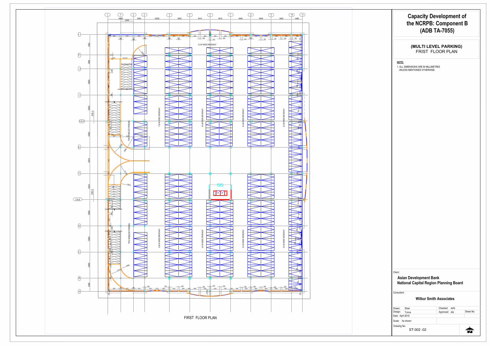
predominant business surrounding of the area, ground floor is set aside for commercial purpose. Brick walls are proposed along the exterior of the ground floor with partition inside. Typical floor plans are presented in Figure 3-1and Figure 3-2. Detailed floor plans, sections and elevations are presented in Appendix 1.

WSA_NCRPB_FR MLPGZB (15 Jul 10)
24
Table 3-1: Particulars of Proposed Multi-level Parking Facility S.
No. Parameter Unit Value
1 Site area Sq. m 10,040 2 Area (Ground Floor) Sq. m 8,323 3 Area (1st, 2nd and 3rd Floors) Sq. m 25,833 3 Commercial/Retail (Ground Floor) Sq. m 5,000 4 Parking (Ground Floor) – 2-wheelers No. s 117 5 Parking (1st floor ) – 2-wheelers No. s 213 6 Parking (1st, 2nd and 3rd Floors) – Cars No.s 777

WSA_NCRPB_FR MLPGZB (15 Jul 10)
25
Figure 3-1: Ground Floor Plan of the Proposed Multilevel Parking
L
K
J
I
H & H'
G
F
E & E'
D
C
B
A
20(E
.J)20
(E.J)
Entrance
Exit
X X
Road
RoadFlyover - NH 24
Am
bedkar Roa d
GROUND FLOOR PLAN
1 1' 2 3 4 5 6 7 8 9 10 11
Column to be terminatedfrom First Floor
Column to be terminatedfrom First Floor

WSA_NCRPB_FR MLPGZB (15 Jul 10)
26
Figure 3-2: Typical Floor Plan of the Proposed Multilevel Parking Facility
L
K
J
I
H & H'
G
F
E & E'
D
C
B
A
20(E
.J)20
(E.J)
X X
Am
bedka r Roa d
1 1' 2 3 4 5 6 7 8 9 10 11
6.0
M W
IDE
DRI
VEW
AY
6.0
M W
IDE
DRI
VEW
AY
6.0
M W
IDE
DRI
VEW
AY
5.80
M W
IDE
DR
IVEW
AY
6.0
M W
IDE
DR
IVEW
AY
6.0
M W
IDE
DR
IVEW
AY
6.0
M W
IDE
DR
IVEW
AY
TWO
WH
EELE
R P
AR
KIN
G
5.5 M WIDE DRIVEWAY
7.50
M W
IDE
DRI
VEW
AY
TWO
WH
EELE
R P
AR
KIN
G
20(E
.J)20
(E.J)
Column to be terminatedfrom First Floor
Column to be terminatedfrom First Floor
Typical Floor Plan

WSA_NCRPB_FR MLPGZB (15 Jul 10)
27
D. Structural System 63. The proposed building is 80.46m long and 106.5m wide with a plinth area of 8569 sq.m
for each floor. The floor height shall be 3.6m. A combination of column beam arrangement is proposed for the building. Large column spacing of 10.8m is adopted along the breadth and 8.4m is given lengthwise to facilitate easy vehicle movement. Considering the larger size of slab panels, grid beam arrangement is proposed for floors and roof. Ordinary beam slab arrangement is adopted for ramps. Mild condition of exposure is considered in design. Isolated, combined and raft foundations are the different types of foundations adopted. The minimum depth of foundation shall generally be 2.5 m below ground.
64. Salient features of the building are:
− Length 80.46m − Breadth 106.50m − Column spacing (along the length): varies from 8.4m to 4.96m. − Column spacing (along the breadth):10.8m − Column spacing for ramp (along the length): 5.345m − Column spacing for ramp (along the breadth): varies from 8.36m to 5.46m. − Plinth area: 8569 sq.m
65. Design criterion.
− Exposure Condition - Mild (as per IS 456 – Table Clause 8.2.2.1 & 5.3.2) − Grade of Concrete – M30 (as per IS 456 – Table 5 Clause 6.1.2, 8.2.4.1 & 9.1.2) − Reinforcing Steel - Fe 415 conforming to IS 1786. − Safe Bearing Capacity of the soil considered – 225 KN/m2 − Depth of foundation – 2.5m below ground
66. Design codes and standards. 67. The structural design is carried out as per the latest versions of Indian Standard codes
published by Bureau of Indian Standards. Various design codes and standards referred are: − IS 456 for Plain and Reinforced Concrete. − IS 875 Part 1,2,3 & 5 for dead load, live load, wind load and combinations − SP 34 for detailing of reinforcement
68. Ghaziabad being in seismic zone IV, the earthquake resistant design became mandatory.
The codes followed are:

WSA_NCRPB_FR MLPGZB (15 Jul 10)
28
− IS 1893 Part I for earthquake resistant design and − IS 13920 for ductile detailing of reinforced concrete subjected to seismic forces.
69. Loads considered.
(i) Self Weight of members (ii) Wall Load (iii) Slab Live Load (3kN/m2 as per IS 875 Part II) (iv) Stair/Lift/Ramp Load (v) Load due to Wind
70. For wind load the four Cases considered are:
− Wind force acting in X direction − Wind acting in -X direction − Wind force acting in Z direction − Wind acting in -Z direction
71. Wind Load Analysis. General load combinations considered in the design are: (as per IS
456 – Table 18 Clause 18.2.3.1, 36.4 & B-4.3)
− 1.5 * (DL+WX) − 1.5 * (DL-WX) − 1.5 * (DL+WZ) − 1.5 * (DL-WZ) − 1.2 * (DL+LL+WX) − 1.2 * (DL+LL-WX) − 1.2 * (DL+LL+WZ) − 1.2 * (DL+LL-WZ) − 0.9 * DL+ 1.5 * WX − 0.9 * DL - 1.5 * WX − 0.9 * DL+ 1.5 * WZ − 0.9 * DL - 1.5 * WZ
72. Load due to Earthquake. The two cases considered are: (i) force acting in X direction, and
(ii) force acting in Z direction: Load combinations considered are: − 1.5 * (DL+LL) − 1.5 * (DL+EQX) − 1.5 * (DL-EQX) − 1.5 * (DL+EQZ) − 1.5 * (DL-EQZ)

WSA_NCRPB_FR MLPGZB (15 Jul 10)
29
− 1.2 * (DL+LL+EQX) − 1.2 * (DL+LL-EQX) − 1.2 * (DL+LL+EQZ) − 1.2 * (DL+LL-EQZ) − 0.9 * DL+ 1.5 * EQX − 0.9 * DL - 1.5 * EQX − 0.9 * DL+ 1.5 * EQZ − 0.9 * DL - 1.5 * EQZ
73. Following densities and load values are considered for design:
(i) Density of Reinforced concrete: 24 kN/m3 (ii) Density of brick masonry : 18.85 kN/m3 (iii) Density of earth : 18 kN/m3 (iv) Superimposed Live Load : 4 kN/m2 (iv) Floor Finishes : 1 kN/m2
74. Data for wind load design.
(i) Basic wind speed – Ghaziabad 47 m/sec (Appendix A Clause 5.2) (ii) Wind Intensity – 1.73 kN/m2
75. Criteria for Earthquake Resistant Design of Structures. (IS 1893-2002) Clause 6.3.1.2
Partial safety factors for limit state design of reinforced concrete and prestressed concrete structures.
76. In the limit state design of reinforced concrete structures, the following load combinations
are to be accounted for:
(i) 1.5(DL+IL) (ii) 1.2(DL+IL±EL) (iii) 1.5(DL±EL) (iv) 0.9DL±1.5EL
77. Factors Considered for Earth Quake Analysis.
− Ghaziabad is Located in Zone IV − Zone Factor : 0.24 − Importance Factor : 1.5 − Response Reduction Factor : 3.0 − Rock & Soil Site Factor : 1.0

WSA_NCRPB_FR MLPGZB (15 Jul 10)
30
− Damping Ratio : 0.5 − Suitable increase in SBC is considered as per IS 1893-2002
Ref: [Table1 Percentage of Permissible Increase in Allowable Bearing Pressure or
Resistance of Soils (clause6.3.5.2)] For Medium soil - Percentage of Permissible Increase is 25% for isolated RCC
footing without tie beams, or unreinforced strip foundations. 78. Clear cover to reinforcement. The following clear cover to the outer reinforcement shall
be adopted:
− For Foundation : 50 mm. − For Beams : 30 mm. − For Slabs : 20mm. − For columns : 40 mm.
79. The framed system is analyzed as a 3D structure using STAAD Pro 2007. The member
forces and moments from the STAAD output are taken for the design. The beams are designed as singly reinforced as well as doubly reinforced depending upon the requirement. The columns are designed as square or rectangular in shape. The slabs supported by beams and columns are designed using the method specified in Annexure D of IS 456:2000 and the grid slab is designed as normal practice. The various structural elements are designed for the worst combination of loads.
E. Analysis of the Multilevel Parking 80. Multilevel Parking has a plinth area 8569 sq.m with length of 80.46 and width of 106.5m.
Ramp will have a width of 10.69m with varying length. STAAD Pro 2007 is used for the modeling of the structure. For the accuracy of results the whole structure has been split into number of units & modeled separately such as ramp portion, lift & staircase & also for different panels within the structure.
81. To take care of temperature stresses in slab an expansion joint of 20 mm is provided along
the width of the structure. Two expansion joints are provided forming a total of three sections of 35.587m, 32.045m & 37.693m.
82. Based on the axial load following types of footings are designed:
• Raft foundation of 14.5m x 8.5 for lift & staircase portion • Isolated footings of 6 different sizes. • Combined Footings of 10 different sizes.
83. Details are given in the structural drawings. All footings shall have a minimum depth of
WSA_NCRPB_FR MLPGZB (15 Jul 10)
31
2.5m from ground level based on the bearing capacity of the soil. 84. Columns were designed for biaxial bending considering axial Load & moments in X & Y
directions. There are about 10 different types of columns within the structure considering span & load.
85. Slab of structure is designed for traffic load of 3kN/m2 (as per IS 875 Part II) with
additional 25% is taken as impact load. Therefore overall super imposed load is taken as 4kN/m2 considering overall safety of the structure. The slab is designed as grid slab to give more stability & to enhance serviceability. Whereas the slab in the ramp portion is designed as ordinary slab & beam arrangement to facilitate the slope of the ramp.
86. Seismic Analysis. Static Equivalent Method is used for the seismic analysis utilizing the
rules of IS: 1893(part 1) – 2002. 87. Methodology. In seismic load generation using a static equivalent approach, encompassed
in code IS 1893, the weights in the structure are specified. There are three methods for specifying the weights: self weight, joint weight and member weight. Weights, which could be treated as being lumped at a node, could be assigned using Joint Weight the same has been used during this analysis.
88. The joint loads at all the nodes are obtained from the initial analysis by assuming pinned
supports at all the beam column joints. These loads are applied as weight for the seismic analysis.
89. Analysis of this system for all the loads/load combinations is carried out. Please refer
following appendices for detailed structural analysis and drawings.
Appendix 2: STAAD Model Appendix 3: STAAD Input File Appendix 4: Design of Footing Appendix 5: Design of Columns Appendix 6: Design of Beams Appendix 7: Design of Slab Appendix 8: Structural Drawings

WSA_NCRPB_FR MLPGZB (15 Jul 10)
32
4. COST ESTIMATES
A. Rate Analysis 90. The unit rates shall be arrived by considering the basic rates, lead distances, man power,
machinery, and materials. The unit rate for every individual item is arrived based on Uttar Pradesh Lok Nirman Vibhag (UP Public Works Department), Schedule of Rates for Ghaziabad District 2008 and Central Public Works Department Delhi, Schedule of rates 2007. For items of work with no rates specified in the schedule of rates, market rates are obtained and used.
B. Bill of Quantities & Cost Estimates 91. Total item wise quantities are calculated as per the detailed drawings. Separate heads for
all different items of work is included in the BOQ. The major work items considered are:
• Earth work excavation • Concrete
o PCC leveling Course o Reinforced Cement concrete M30
Foundation For walls, columns, beams, slab etc
• Steel o Reinforcement
Foundation For Walls, columns, beams, slab etc
• Electrical cost • Miscellaneous Items
o caution/warning Signs, expansion joints, and etc., o Painting, white washing, finishes and etc.
92. The total based cost of this Multi-level Parking Project works out to be INR 366.8 million.
Bill of quantities and detailed quantities and estimates are presented in Appendix 9.

Appendix 1


STAAD MODEL

Multi Level Car Parking Lift & Stair Portion
MODEL
9

Multi Level Car Parking Central Portion with Column Spacing of 10.8 x 8.4
10.80m
8.40m
10

Raft Slab
11

Multi Level Car Parking Ramp Portion
12

STAAD INPUT FILE
STAAD INPUT FILE STAAD SPACE START JOB INFORMATION ENGINEER DATE 09-Dec-09 END JOB INFORMATION INPUT WIDTH 79 UNIT METER KN JOINT COORDINATES 1 0 0.8 0; 2 10.8 0.8 0; 3 21.6 0.8 0; 4 32.4 0.8 0; 5 0 3.3 0; 6 10.8 3.3 0; 7 21.6 3.3 0; 8 32.4 3.3 0; 9 0 0.8 8.4; 10 10.8 0.8 8.4; 11 21.6 0.8 8.4; 12 32.4 0.8 8.4; 13 0 3.3 8.4; 14 10.8 3.3 8.4; 15 21.6 3.3 8.4; 16 32.4 3.3 8.4; 17 0 0.8 16.8; 18 10.8 0.8 16.8; 19 21.6 0.8 16.8; 20 32.4 0.8 16.8; 21 0 3.3 16.8; 22 10.8 3.3 16.8; 23 21.6 3.3 16.8; 24 32.4 3.3 16.8; 25 0 0.8 25.2; 26 10.8 0.8 25.2; 27 21.6 0.8 25.2; 28 32.4 0.8 25.2; 29 0 3.3 25.2; 30 10.8 3.3 25.2; 31 21.6 3.3 25.2; 32 32.4 3.3 25.2; 33 0 6.9 0; 34 10.8 6.9 0; 35 21.6 6.9 0; 36 32.4 6.9 0; 37 0 6.9 8.4; 38 10.8 6.9 8.4; 39 21.6 6.9 8.4; 40 32.4 6.9 8.4; 41 0 6.9 16.8; 42 10.8 6.9 16.8; 43 21.6 6.9 16.8; 44 32.4 6.9 16.8; 45 0 6.9 25.2; 46 10.8 6.9 25.2; 47 21.6 6.9 25.2; 48 32.4 6.9 25.2; 49 1.35 6.9 0; 50 2.7 6.9 0; 51 4.05 6.9 0; 52 5.4 6.9 0; 53 6.75 6.9 0; 54 8.1 6.9 0; 55 9.45 6.9 0; 56 0 6.9 1.4; 57 0 6.9 2.8; 58 0 6.9 4.2; 59 0 6.9 5.6; 60 0 6.9 7; 61 12.15 6.9 0; 62 13.5 6.9 0; 63 14.85 6.9 0; 64 16.2 6.9 0; 65 17.55 6.9 0; 66 18.9 6.9 0; 67 20.25 6.9 0; 68 22.95 6.9 0; 69 24.3 6.9 0; 70 25.65 6.9 0; 71 27 6.9 0; 72 28.35 6.9 0; 73 29.7 6.9 0; 74 31.05 6.9 0; 75 0 6.9 9.8; 76 0 6.9 11.2; 77 0 6.9 12.6; 78 0 6.9 14; 79 0 6.9 15.4; 80 0 6.9 18.2; 81 0 6.9 19.6; 82 0 6.9 21; 83 0 6.9 22.4; 84 0 6.9 23.8; 85 1.35 6.9 8.4; 86 2.7 6.9 8.4; 87 4.05 6.9 8.4; 88 5.4 6.9 8.4; 89 6.75 6.9 8.4; 90 8.1 6.9 8.4; 91 9.45 6.9 8.4; 92 12.15 6.9 8.4; 93 13.5 6.9 8.4; 94 14.85 6.9 8.4; 95 16.2 6.9 8.4; 96 17.55 6.9 8.4; 97 18.9 6.9 8.4; 98 20.25 6.9 8.4; 99 22.95 6.9 8.4; 100 24.3 6.9 8.4; 101 25.65 6.9 8.4; 102 27 6.9 8.4; 103 28.35 6.9 8.4; 104 29.7 6.9 8.4; 105 31.05 6.9 8.4; 106 1.35 6.9 16.8; 107 2.7 6.9 16.8; 108 4.05 6.9 16.8; 109 5.4 6.9 16.8; 110 6.75 6.9 16.8; 111 8.1 6.9 16.8; 112 9.45 6.9 16.8; 113 12.15 6.9 16.8; 114 13.5 6.9 16.8; 115 14.85 6.9 16.8; 116 16.2 6.9 16.8; 117 17.55 6.9 16.8; 118 18.9 6.9 16.8; 119 20.25 6.9 16.8; 120 22.95 6.9 16.8; 121 24.3 6.9 16.8; 122 25.65 6.9 16.8; 123 27 6.9 16.8; 124 28.35 6.9 16.8; 125 29.7 6.9 16.8; 126 31.05 6.9 16.8; 127 1.35 6.9 25.2; 128 2.7 6.9 25.2; 129 4.05 6.9 25.2; 130 5.4 6.9 25.2; 131 6.75 6.9 25.2; 132 8.1 6.9 25.2; 133 9.45 6.9 25.2; 134 12.15 6.9 25.2; 135 13.5 6.9 25.2; 136 14.85 6.9 25.2; 137 16.2 6.9 25.2; 138 17.55 6.9 25.2; 139 18.9 6.9 25.2; 140 20.25 6.9 25.2; 141 22.95 6.9 25.2; 142 24.3 6.9 25.2; 143 25.65 6.9 25.2; 144 27 6.9 25.2; 145 28.35 6.9 25.2; 146 29.7 6.9 25.2; 147 31.05 6.9 25.2; 148 10.8 6.9 1.4; 149 10.8 6.9 2.8; 150 10.8 6.9 4.2; 151 10.8 6.9 5.6; 152 10.8 6.9 7; 153 21.6 6.9 1.4; 154 21.6 6.9 2.8; 155 21.6 6.9 4.2; 156 21.6 6.9 5.6; 157 21.6 6.9 7; 158 32.4 6.9 1.4; 159 32.4 6.9 2.8; 160 32.4 6.9 4.2; 161 32.4 6.9 5.6; 162 32.4 6.9 7; 163 10.8 6.9 9.8; 164 10.8 6.9 11.2; 165 10.8 6.9 12.6; 166 10.8 6.9 14; 167 10.8 6.9 15.4; 168 21.6 6.9 9.8; 169 21.6 6.9 11.2; 170 21.6 6.9 12.6; 171 21.6 6.9 14; 172 21.6 6.9 15.4; 173 32.4 6.9 9.8; 174 32.4 6.9 11.2; 175 32.4 6.9 12.6; 176 32.4 6.9 14; 177 32.4 6.9 15.4; 178 10.8 6.9 18.2; 179 10.8 6.9 19.6; 180 10.8 6.9 21; 181 10.8 6.9 22.4; 182 10.8 6.9 23.8; 183 21.6 6.9 18.2; 184 21.6 6.9 19.6; 185 21.6 6.9 21; 186 21.6 6.9 22.4; 187 21.6 6.9 23.8; 188 32.4 6.9 18.2; 189 32.4 6.9 19.6; 190 32.4 6.9 21; 191 32.4 6.9 22.4; 192 32.4 6.9 23.8; 193 1.35 6.9 1.4; 194 1.35 6.9 2.8; 195 1.35 6.9 4.2; 196 1.35 6.9 5.6; 197 1.35 6.9 7; 198 2.7 6.9 1.4; 199 2.7 6.9 2.8; 200 2.7 6.9 4.2; 201 2.7 6.9 5.6; 202 2.7 6.9 7; 203 4.05 6.9 1.4; 204 4.05 6.9 2.8; 205 4.05 6.9 4.2; 206 4.05 6.9 5.6; 207 4.05 6.9 7; 208 5.4 6.9 1.4; 209 5.4 6.9 2.8; 210 5.4 6.9 4.2; 211 5.4 6.9 5.6; 212 5.4 6.9 7; 213 6.75 6.9 1.4; 214 6.75 6.9 2.8; 215 6.75 6.9 4.2; 216 6.75 6.9 5.6; 217 6.75 6.9 7; 218 8.1 6.9 1.4; 219 8.1 6.9 2.8; 220 8.1 6.9 4.2; 221 8.1 6.9 5.6; 222 8.1 6.9 7; 223 9.45 6.9 1.4; 224 9.45 6.9 2.8; 225 9.45 6.9 4.2; 226 9.45 6.9 5.6; 227 9.45 6.9 7; 228 12.15 6.9 1.4;
13

229 12.15 6.9 2.8; 230 12.15 6.9 4.2; 231 12.15 6.9 5.6; 232 12.15 6.9 7; 233 13.5 6.9 1.4; 234 13.5 6.9 2.8; 235 13.5 6.9 4.2; 236 13.5 6.9 5.6; 237 13.5 6.9 7; 238 14.85 6.9 1.4; 239 14.85 6.9 2.8; 240 14.85 6.9 4.2; 241 14.85 6.9 5.6; 242 14.85 6.9 7; 243 16.2 6.9 1.4; 244 16.2 6.9 2.8; 245 16.2 6.9 4.2; 246 16.2 6.9 5.6; 247 16.2 6.9 7; 248 17.55 6.9 1.4; 249 17.55 6.9 2.8; 250 17.55 6.9 4.2; 251 17.55 6.9 5.6; 252 17.55 6.9 7; 253 18.9 6.9 1.4; 254 18.9 6.9 2.8; 255 18.9 6.9 4.2; 256 18.9 6.9 5.6; 257 18.9 6.9 7; 258 20.25 6.9 1.4; 259 20.25 6.9 2.8; 260 20.25 6.9 4.2; 261 20.25 6.9 5.6; 262 20.25 6.9 7; 263 22.95 6.9 1.4; 264 22.95 6.9 2.8; 265 22.95 6.9 4.2; 266 22.95 6.9 5.6; 267 22.95 6.9 7; 268 24.3 6.9 1.4; 269 24.3 6.9 2.8; 270 24.3 6.9 4.2; 271 24.3 6.9 5.6; 272 24.3 6.9 7; 273 25.65 6.9 1.4; 274 25.65 6.9 2.8; 275 25.65 6.9 4.2; 276 25.65 6.9 5.6; 277 25.65 6.9 7; 278 27 6.9 1.4; 279 27 6.9 2.8; 280 27 6.9 4.2; 281 27 6.9 5.6; 282 27 6.9 7; 283 28.35 6.9 1.4; 284 28.35 6.9 2.8; 285 28.35 6.9 4.2; 286 28.35 6.9 5.6; 287 28.35 6.9 7; 288 29.7 6.9 1.4; 289 29.7 6.9 2.8; 290 29.7 6.9 4.2; 291 29.7 6.9 5.6; 292 29.7 6.9 7; 293 31.05 6.9 1.4; 294 31.05 6.9 2.8; 295 31.05 6.9 4.2; 296 31.05 6.9 5.6; 297 31.05 6.9 7; 298 1.35 6.9 9.8; 299 1.35 6.9 11.2; 300 1.35 6.9 12.6; 301 1.35 6.9 14; 302 1.35 6.9 15.4; 303 2.7 6.9 9.8; 304 2.7 6.9 11.2; 305 2.7 6.9 12.6; 306 2.7 6.9 14; 307 2.7 6.9 15.4; 308 4.05 6.9 9.8; 309 4.05 6.9 11.2; 310 4.05 6.9 12.6; 311 4.05 6.9 14; 312 4.05 6.9 15.4; 313 5.4 6.9 9.8; 314 5.4 6.9 11.2; 315 5.4 6.9 12.6; 316 5.4 6.9 14; 317 5.4 6.9 15.4; 318 6.75 6.9 9.8; 319 6.75 6.9 11.2; 320 6.75 6.9 12.6; 321 6.75 6.9 14; 322 6.75 6.9 15.4; 323 8.1 6.9 9.8; 324 8.1 6.9 11.2; 325 8.1 6.9 12.6; 326 8.1 6.9 14; 327 8.1 6.9 15.4; 328 9.45 6.9 9.8; 329 9.45 6.9 11.2; 330 9.45 6.9 12.6; 331 9.45 6.9 14; 332 9.45 6.9 15.4; 333 12.15 6.9 9.8; 334 12.15 6.9 11.2; 335 12.15 6.9 12.6; 336 12.15 6.9 14; 337 12.15 6.9 15.4; 338 13.5 6.9 9.8; 339 13.5 6.9 11.2; 340 13.5 6.9 12.6; 341 13.5 6.9 14; 342 13.5 6.9 15.4; 343 14.85 6.9 9.8; 344 14.85 6.9 11.2; 345 14.85 6.9 12.6; 346 14.85 6.9 14; 347 14.85 6.9 15.4; 348 16.2 6.9 9.8; 349 16.2 6.9 11.2; 350 16.2 6.9 12.6; 351 16.2 6.9 14; 352 16.2 6.9 15.4; 353 17.55 6.9 9.8; 354 17.55 6.9 11.2; 355 17.55 6.9 12.6; 356 17.55 6.9 14; 357 17.55 6.9 15.4; 358 18.9 6.9 9.8; 359 18.9 6.9 11.2; 360 18.9 6.9 12.6; 361 18.9 6.9 14; 362 18.9 6.9 15.4; 363 20.25 6.9 9.8; 364 20.25 6.9 11.2; 365 20.25 6.9 12.6; 366 20.25 6.9 14; 367 20.25 6.9 15.4; 368 22.95 6.9 9.8; 369 22.95 6.9 11.2; 370 22.95 6.9 12.6; 371 22.95 6.9 14; 372 22.95 6.9 15.4; 373 24.3 6.9 9.8; 374 24.3 6.9 11.2; 375 24.3 6.9 12.6; 376 24.3 6.9 14; 377 24.3 6.9 15.4; 378 25.65 6.9 9.8; 379 25.65 6.9 11.2; 380 25.65 6.9 12.6; 381 25.65 6.9 14; 382 25.65 6.9 15.4; 383 27 6.9 9.8; 384 27 6.9 11.2; 385 27 6.9 12.6; 386 27 6.9 14; 387 27 6.9 15.4; 388 28.35 6.9 9.8; 389 28.35 6.9 11.2; 390 28.35 6.9 12.6; 391 28.35 6.9 14; 392 28.35 6.9 15.4; 393 29.7 6.9 9.8; 394 29.7 6.9 11.2; 395 29.7 6.9 12.6; 396 29.7 6.9 14; 397 29.7 6.9 15.4; 398 31.05 6.9 9.8; 399 31.05 6.9 11.2; 400 31.05 6.9 12.6; 401 31.05 6.9 14; 402 31.05 6.9 15.4; 403 1.35 6.9 18.2; 404 1.35 6.9 19.6; 405 1.35 6.9 21; 406 1.35 6.9 22.4; 407 1.35 6.9 23.8; 408 2.7 6.9 18.2; 409 2.7 6.9 19.6; 410 2.7 6.9 21; 411 2.7 6.9 22.4; 412 2.7 6.9 23.8; 413 4.05 6.9 18.2; 414 4.05 6.9 19.6; 415 4.05 6.9 21; 416 4.05 6.9 22.4; 417 4.05 6.9 23.8; 418 5.4 6.9 18.2; 419 5.4 6.9 19.6; 420 5.4 6.9 21; 421 5.4 6.9 22.4; 422 5.4 6.9 23.8; 423 6.75 6.9 18.2; 424 6.75 6.9 19.6; 425 6.75 6.9 21; 426 6.75 6.9 22.4; 427 6.75 6.9 23.8; 428 8.1 6.9 18.2; 429 8.1 6.9 19.6; 430 8.1 6.9 21; 431 8.1 6.9 22.4; 432 8.1 6.9 23.8; 433 9.45 6.9 18.2; 434 9.45 6.9 19.6; 435 9.45 6.9 21; 436 9.45 6.9 22.4; 437 9.45 6.9 23.8; 438 12.15 6.9 18.2; 439 12.15 6.9 19.6; 440 12.15 6.9 21; 441 12.15 6.9 22.4; 442 12.15 6.9 23.8; 443 13.5 6.9 18.2; 444 13.5 6.9 19.6; 445 13.5 6.9 21; 446 13.5 6.9 22.4; 447 13.5 6.9 23.8; 448 14.85 6.9 18.2; 449 14.85 6.9 19.6; 450 14.85 6.9 21; 451 14.85 6.9 22.4; 452 14.85 6.9 23.8; 453 16.2 6.9 18.2; 454 16.2 6.9 19.6; 455 16.2 6.9 21; 456 16.2 6.9 22.4; 457 16.2 6.9 23.8; 458 17.55 6.9 18.2; 459 17.55 6.9 19.6; 460 17.55 6.9 21; 461 17.55 6.9 22.4; 462 17.55 6.9 23.8; 463 18.9 6.9 18.2; 464 18.9 6.9 19.6; 465 18.9 6.9 21; 466 18.9 6.9 22.4; 467 18.9 6.9 23.8; 468 20.25 6.9 18.2; 469 20.25 6.9 19.6; 470 20.25 6.9 21; 471 20.25 6.9 22.4; 472 20.25 6.9 23.8; 473 22.95 6.9 18.2; 474 22.95 6.9 19.6; 475 22.95 6.9 21; 476 22.95 6.9 22.4; 477 22.95 6.9 23.8; 478 24.3 6.9 18.2; 479 24.3 6.9 19.6; 480 24.3 6.9 21;
14

481 24.3 6.9 22.4; 482 24.3 6.9 23.8; 483 25.65 6.9 18.2; 484 25.65 6.9 19.6; 485 25.65 6.9 21; 486 25.65 6.9 22.4; 487 25.65 6.9 23.8; 488 27 6.9 18.2; 489 27 6.9 19.6; 490 27 6.9 21; 491 27 6.9 22.4; 492 27 6.9 23.8; 493 28.35 6.9 18.2; 494 28.35 6.9 19.6; 495 28.35 6.9 21; 496 28.35 6.9 22.4; 497 28.35 6.9 23.8; 498 29.7 6.9 18.2; 499 29.7 6.9 19.6; 500 29.7 6.9 21; 501 29.7 6.9 22.4; 502 29.7 6.9 23.8; 503 31.05 6.9 18.2; 504 31.05 6.9 19.6; 505 31.05 6.9 21; 506 31.05 6.9 22.4; 507 31.05 6.9 23.8; 508 0 10.5 0; 509 10.8 10.5 0; 510 21.6 10.5 0; 511 32.4 10.5 0; 512 0 10.5 8.4; 513 10.8 10.5 8.4; 514 21.6 10.5 8.4; 515 32.4 10.5 8.4; 516 0 10.5 16.8; 517 10.8 10.5 16.8; 518 21.6 10.5 16.8; 519 32.4 10.5 16.8; 520 0 10.5 25.2; 521 10.8 10.5 25.2; 522 21.6 10.5 25.2; 523 32.4 10.5 25.2; 524 1.35 10.5 0; 525 2.7 10.5 0; 526 4.05 10.5 0; 527 5.4 10.5 0; 528 6.75 10.5 0; 529 8.1 10.5 0; 530 9.45 10.5 0; 531 0 10.5 1.4; 532 0 10.5 2.8; 533 0 10.5 4.2; 534 0 10.5 5.6; 535 0 10.5 7; 536 12.15 10.5 0; 537 13.5 10.5 0; 538 14.85 10.5 0; 539 16.2 10.5 0; 540 17.55 10.5 0; 541 18.9 10.5 0; 542 20.25 10.5 0; 543 22.95 10.5 0; 544 24.3 10.5 0; 545 25.65 10.5 0; 546 27 10.5 0; 547 28.35 10.5 0; 548 29.7 10.5 0; 549 31.05 10.5 0; 550 0 10.5 9.8; 551 0 10.5 11.2; 552 0 10.5 12.6; 553 0 10.5 14; 554 0 10.5 15.4; 555 0 10.5 18.2; 556 0 10.5 19.6; 557 0 10.5 21; 558 0 10.5 22.4; 559 0 10.5 23.8; 560 1.35 10.5 8.4; 561 2.7 10.5 8.4; 562 4.05 10.5 8.4; 563 5.4 10.5 8.4; 564 6.75 10.5 8.4; 565 8.1 10.5 8.4; 566 9.45 10.5 8.4; 567 12.15 10.5 8.4; 568 13.5 10.5 8.4; 569 14.85 10.5 8.4; 570 16.2 10.5 8.4; 571 17.55 10.5 8.4; 572 18.9 10.5 8.4; 573 20.25 10.5 8.4; 574 22.95 10.5 8.4; 575 24.3 10.5 8.4; 576 25.65 10.5 8.4; 577 27 10.5 8.4; 578 28.35 10.5 8.4; 579 29.7 10.5 8.4; 580 31.05 10.5 8.4; 581 1.35 10.5 16.8; 582 2.7 10.5 16.8; 583 4.05 10.5 16.8; 584 5.4 10.5 16.8; 585 6.75 10.5 16.8; 586 8.1 10.5 16.8; 587 9.45 10.5 16.8; 588 12.15 10.5 16.8; 589 13.5 10.5 16.8; 590 14.85 10.5 16.8; 591 16.2 10.5 16.8; 592 17.55 10.5 16.8; 593 18.9 10.5 16.8; 594 20.25 10.5 16.8; 595 22.95 10.5 16.8; 596 24.3 10.5 16.8; 597 25.65 10.5 16.8; 598 27 10.5 16.8; 599 28.35 10.5 16.8; 600 29.7 10.5 16.8; 601 31.05 10.5 16.8; 602 1.35 10.5 25.2; 603 2.7 10.5 25.2; 604 4.05 10.5 25.2; 605 5.4 10.5 25.2; 606 6.75 10.5 25.2; 607 8.1 10.5 25.2; 608 9.45 10.5 25.2; 609 12.15 10.5 25.2; 610 13.5 10.5 25.2; 611 14.85 10.5 25.2; 612 16.2 10.5 25.2; 613 17.55 10.5 25.2; 614 18.9 10.5 25.2; 615 20.25 10.5 25.2; 616 22.95 10.5 25.2; 617 24.3 10.5 25.2; 618 25.65 10.5 25.2; 619 27 10.5 25.2; 620 28.35 10.5 25.2; 621 29.7 10.5 25.2; 622 31.05 10.5 25.2; 623 10.8 10.5 1.4; 624 10.8 10.5 2.8; 625 10.8 10.5 4.2; 626 10.8 10.5 5.6; 627 10.8 10.5 7; 628 21.6 10.5 1.4; 629 21.6 10.5 2.8; 630 21.6 10.5 4.2; 631 21.6 10.5 5.6; 632 21.6 10.5 7; 633 32.4 10.5 1.4; 634 32.4 10.5 2.8; 635 32.4 10.5 4.2; 636 32.4 10.5 5.6; 637 32.4 10.5 7; 638 10.8 10.5 9.8; 639 10.8 10.5 11.2; 640 10.8 10.5 12.6; 641 10.8 10.5 14; 642 10.8 10.5 15.4; 643 21.6 10.5 9.8; 644 21.6 10.5 11.2; 645 21.6 10.5 12.6; 646 21.6 10.5 14; 647 21.6 10.5 15.4; 648 32.4 10.5 9.8; 649 32.4 10.5 11.2; 650 32.4 10.5 12.6; 651 32.4 10.5 14; 652 32.4 10.5 15.4; 653 10.8 10.5 18.2; 654 10.8 10.5 19.6; 655 10.8 10.5 21; 656 10.8 10.5 22.4; 657 10.8 10.5 23.8; 658 21.6 10.5 18.2; 659 21.6 10.5 19.6; 660 21.6 10.5 21; 661 21.6 10.5 22.4; 662 21.6 10.5 23.8; 663 32.4 10.5 18.2; 664 32.4 10.5 19.6; 665 32.4 10.5 21; 666 32.4 10.5 22.4; 667 32.4 10.5 23.8; 668 1.35 10.5 1.4; 669 1.35 10.5 2.8; 670 1.35 10.5 4.2; 671 1.35 10.5 5.6; 672 1.35 10.5 7; 673 2.7 10.5 1.4; 674 2.7 10.5 2.8; 675 2.7 10.5 4.2; 676 2.7 10.5 5.6; 677 2.7 10.5 7; 678 4.05 10.5 1.4; 679 4.05 10.5 2.8; 680 4.05 10.5 4.2; 681 4.05 10.5 5.6; 682 4.05 10.5 7; 683 5.4 10.5 1.4; 684 5.4 10.5 2.8; 685 5.4 10.5 4.2; 686 5.4 10.5 5.6; 687 5.4 10.5 7; 688 6.75 10.5 1.4; 689 6.75 10.5 2.8; 690 6.75 10.5 4.2; 691 6.75 10.5 5.6; 692 6.75 10.5 7; 693 8.1 10.5 1.4; 694 8.1 10.5 2.8; 695 8.1 10.5 4.2; 696 8.1 10.5 5.6; 697 8.1 10.5 7; 698 9.45 10.5 1.4; 699 9.45 10.5 2.8; 700 9.45 10.5 4.2; 701 9.45 10.5 5.6; 702 9.45 10.5 7; 703 12.15 10.5 1.4; 704 12.15 10.5 2.8; 705 12.15 10.5 4.2; 706 12.15 10.5 5.6; 707 12.15 10.5 7; 708 13.5 10.5 1.4; 709 13.5 10.5 2.8; 710 13.5 10.5 4.2; 711 13.5 10.5 5.6; 712 13.5 10.5 7; 713 14.85 10.5 1.4; 714 14.85 10.5 2.8; 715 14.85 10.5 4.2; 716 14.85 10.5 5.6; 717 14.85 10.5 7; 718 16.2 10.5 1.4; 719 16.2 10.5 2.8; 720 16.2 10.5 4.2; 721 16.2 10.5 5.6; 722 16.2 10.5 7; 723 17.55 10.5 1.4; 724 17.55 10.5 2.8; 725 17.55 10.5 4.2; 726 17.55 10.5 5.6;
15

727 17.55 10.5 7; 728 18.9 10.5 1.4; 729 18.9 10.5 2.8; 730 18.9 10.5 4.2; 731 18.9 10.5 5.6; 732 18.9 10.5 7; 733 20.25 10.5 1.4; 734 20.25 10.5 2.8; 735 20.25 10.5 4.2; 736 20.25 10.5 5.6; 737 20.25 10.5 7; 738 22.95 10.5 1.4; 739 22.95 10.5 2.8; 740 22.95 10.5 4.2; 741 22.95 10.5 5.6; 742 22.95 10.5 7; 743 24.3 10.5 1.4; 744 24.3 10.5 2.8; 745 24.3 10.5 4.2; 746 24.3 10.5 5.6; 747 24.3 10.5 7; 748 25.65 10.5 1.4; 749 25.65 10.5 2.8; 750 25.65 10.5 4.2; 751 25.65 10.5 5.6; 752 25.65 10.5 7; 753 27 10.5 1.4; 754 27 10.5 2.8; 755 27 10.5 4.2; 756 27 10.5 5.6; 757 27 10.5 7; 758 28.35 10.5 1.4; 759 28.35 10.5 2.8; 760 28.35 10.5 4.2; 761 28.35 10.5 5.6; 762 28.35 10.5 7; 763 29.7 10.5 1.4; 764 29.7 10.5 2.8; 765 29.7 10.5 4.2; 766 29.7 10.5 5.6; 767 29.7 10.5 7; 768 31.05 10.5 1.4; 769 31.05 10.5 2.8; 770 31.05 10.5 4.2; 771 31.05 10.5 5.6; 772 31.05 10.5 7; 773 1.35 10.5 9.8; 774 1.35 10.5 11.2; 775 1.35 10.5 12.6; 776 1.35 10.5 14; 777 1.35 10.5 15.4; 778 2.7 10.5 9.8; 779 2.7 10.5 11.2; 780 2.7 10.5 12.6; 781 2.7 10.5 14; 782 2.7 10.5 15.4; 783 4.05 10.5 9.8; 784 4.05 10.5 11.2; 785 4.05 10.5 12.6; 786 4.05 10.5 14; 787 4.05 10.5 15.4; 788 5.4 10.5 9.8; 789 5.4 10.5 11.2; 790 5.4 10.5 12.6; 791 5.4 10.5 14; 792 5.4 10.5 15.4; 793 6.75 10.5 9.8; 794 6.75 10.5 11.2; 795 6.75 10.5 12.6; 796 6.75 10.5 14; 797 6.75 10.5 15.4; 798 8.1 10.5 9.8; 799 8.1 10.5 11.2; 800 8.1 10.5 12.6; 801 8.1 10.5 14; 802 8.1 10.5 15.4; 803 9.45 10.5 9.8; 804 9.45 10.5 11.2; 805 9.45 10.5 12.6; 806 9.45 10.5 14; 807 9.45 10.5 15.4; 808 12.15 10.5 9.8; 809 12.15 10.5 11.2; 810 12.15 10.5 12.6; 811 12.15 10.5 14; 812 12.15 10.5 15.4; 813 13.5 10.5 9.8; 814 13.5 10.5 11.2; 815 13.5 10.5 12.6; 816 13.5 10.5 14; 817 13.5 10.5 15.4; 818 14.85 10.5 9.8; 819 14.85 10.5 11.2; 820 14.85 10.5 12.6; 821 14.85 10.5 14; 822 14.85 10.5 15.4; 823 16.2 10.5 9.8; 824 16.2 10.5 11.2; 825 16.2 10.5 12.6; 826 16.2 10.5 14; 827 16.2 10.5 15.4; 828 17.55 10.5 9.8; 829 17.55 10.5 11.2; 830 17.55 10.5 12.6; 831 17.55 10.5 14; 832 17.55 10.5 15.4; 833 18.9 10.5 9.8; 834 18.9 10.5 11.2; 835 18.9 10.5 12.6; 836 18.9 10.5 14; 837 18.9 10.5 15.4; 838 20.25 10.5 9.8; 839 20.25 10.5 11.2; 840 20.25 10.5 12.6; 841 20.25 10.5 14; 842 20.25 10.5 15.4; 843 22.95 10.5 9.8; 844 22.95 10.5 11.2; 845 22.95 10.5 12.6; 846 22.95 10.5 14; 847 22.95 10.5 15.4; 848 24.3 10.5 9.8; 849 24.3 10.5 11.2; 850 24.3 10.5 12.6; 851 24.3 10.5 14; 852 24.3 10.5 15.4; 853 25.65 10.5 9.8; 854 25.65 10.5 11.2; 855 25.65 10.5 12.6; 856 25.65 10.5 14; 857 25.65 10.5 15.4; 858 27 10.5 9.8; 859 27 10.5 11.2; 860 27 10.5 12.6; 861 27 10.5 14; 862 27 10.5 15.4; 863 28.35 10.5 9.8; 864 28.35 10.5 11.2; 865 28.35 10.5 12.6; 866 28.35 10.5 14; 867 28.35 10.5 15.4; 868 29.7 10.5 9.8; 869 29.7 10.5 11.2; 870 29.7 10.5 12.6; 871 29.7 10.5 14; 872 29.7 10.5 15.4; 873 31.05 10.5 9.8; 874 31.05 10.5 11.2; 875 31.05 10.5 12.6; 876 31.05 10.5 14; 877 31.05 10.5 15.4; 878 1.35 10.5 18.2; 879 1.35 10.5 19.6; 880 1.35 10.5 21; 881 1.35 10.5 22.4; 882 1.35 10.5 23.8; 883 2.7 10.5 18.2; 884 2.7 10.5 19.6; 885 2.7 10.5 21; 886 2.7 10.5 22.4; 887 2.7 10.5 23.8; 888 4.05 10.5 18.2; 889 4.05 10.5 19.6; 890 4.05 10.5 21; 891 4.05 10.5 22.4; 892 4.05 10.5 23.8; 893 5.4 10.5 18.2; 894 5.4 10.5 19.6; 895 5.4 10.5 21; 896 5.4 10.5 22.4; 897 5.4 10.5 23.8; 898 6.75 10.5 18.2; 899 6.75 10.5 19.6; 900 6.75 10.5 21; 901 6.75 10.5 22.4; 902 6.75 10.5 23.8; 903 8.1 10.5 18.2; 904 8.1 10.5 19.6; 905 8.1 10.5 21; 906 8.1 10.5 22.4; 907 8.1 10.5 23.8; 908 9.45 10.5 18.2; 909 9.45 10.5 19.6; 910 9.45 10.5 21; 911 9.45 10.5 22.4; 912 9.45 10.5 23.8; 913 12.15 10.5 18.2; 914 12.15 10.5 19.6; 915 12.15 10.5 21; 916 12.15 10.5 22.4; 917 12.15 10.5 23.8; 918 13.5 10.5 18.2; 919 13.5 10.5 19.6; 920 13.5 10.5 21; 921 13.5 10.5 22.4; 922 13.5 10.5 23.8; 923 14.85 10.5 18.2; 924 14.85 10.5 19.6; 925 14.85 10.5 21; 926 14.85 10.5 22.4; 927 14.85 10.5 23.8; 928 16.2 10.5 18.2; 929 16.2 10.5 19.6; 930 16.2 10.5 21; 931 16.2 10.5 22.4; 932 16.2 10.5 23.8; 933 17.55 10.5 18.2; 934 17.55 10.5 19.6; 935 17.55 10.5 21; 936 17.55 10.5 22.4; 937 17.55 10.5 23.8; 938 18.9 10.5 18.2; 939 18.9 10.5 19.6; 940 18.9 10.5 21; 941 18.9 10.5 22.4; 942 18.9 10.5 23.8; 943 20.25 10.5 18.2; 944 20.25 10.5 19.6; 945 20.25 10.5 21; 946 20.25 10.5 22.4; 947 20.25 10.5 23.8; 948 22.95 10.5 18.2; 949 22.95 10.5 19.6; 950 22.95 10.5 21; 951 22.95 10.5 22.4; 952 22.95 10.5 23.8; 953 24.3 10.5 18.2; 954 24.3 10.5 19.6; 955 24.3 10.5 21; 956 24.3 10.5 22.4; 957 24.3 10.5 23.8; 958 25.65 10.5 18.2; 959 25.65 10.5 19.6; 960 25.65 10.5 21;
16

961 25.65 10.5 22.4; 962 25.65 10.5 23.8; 963 27 10.5 18.2; 964 27 10.5 19.6; 965 27 10.5 21; 966 27 10.5 22.4; 967 27 10.5 23.8; 968 28.35 10.5 18.2; 969 28.35 10.5 19.6; 970 28.35 10.5 21; 971 28.35 10.5 22.4; 972 28.35 10.5 23.8; 973 29.7 10.5 18.2; 974 29.7 10.5 19.6; 975 29.7 10.5 21; 976 29.7 10.5 22.4; 977 29.7 10.5 23.8; 978 31.05 10.5 18.2; 979 31.05 10.5 19.6; 980 31.05 10.5 21; 981 31.05 10.5 22.4; 982 31.05 10.5 23.8; 983 0 14.1 0; 984 10.8 14.1 0; 985 21.6 14.1 0; 986 32.4 14.1 0; 987 0 14.1 8.4; 988 10.8 14.1 8.4; 989 21.6 14.1 8.4; 990 32.4 14.1 8.4; 991 0 14.1 16.8; 992 10.8 14.1 16.8; 993 21.6 14.1 16.8; 994 32.4 14.1 16.8; 995 0 14.1 25.2; 996 10.8 14.1 25.2; 997 21.6 14.1 25.2; 998 32.4 14.1 25.2; 999 1.35 14.1 0; 1000 2.7 14.1 0; 1001 4.05 14.1 0; 1002 5.4 14.1 0; 1003 6.75 14.1 0; 1004 8.1 14.1 0; 1005 9.45 14.1 0; 1006 0 14.1 1.4; 1007 0 14.1 2.8; 1008 0 14.1 4.2; 1009 0 14.1 5.6; 1010 0 14.1 7; 1011 12.15 14.1 0; 1012 13.5 14.1 0; 1013 14.85 14.1 0; 1014 16.2 14.1 0; 1015 17.55 14.1 0; 1016 18.9 14.1 0; 1017 20.25 14.1 0; 1018 22.95 14.1 0; 1019 24.3 14.1 0; 1020 25.65 14.1 0; 1021 27 14.1 0; 1022 28.35 14.1 0; 1023 29.7 14.1 0; 1024 31.05 14.1 0; 1025 0 14.1 9.8; 1026 0 14.1 11.2; 1027 0 14.1 12.6; 1028 0 14.1 14; 1029 0 14.1 15.4; 1030 0 14.1 18.2; 1031 0 14.1 19.6; 1032 0 14.1 21; 1033 0 14.1 22.4; 1034 0 14.1 23.8; 1035 1.35 14.1 8.4; 1036 2.7 14.1 8.4; 1037 4.05 14.1 8.4; 1038 5.4 14.1 8.4; 1039 6.75 14.1 8.4; 1040 8.1 14.1 8.4; 1041 9.45 14.1 8.4; 1042 12.15 14.1 8.4; 1043 13.5 14.1 8.4; 1044 14.85 14.1 8.4; 1045 16.2 14.1 8.4; 1046 17.55 14.1 8.4; 1047 18.9 14.1 8.4; 1048 20.25 14.1 8.4; 1049 22.95 14.1 8.4; 1050 24.3 14.1 8.4; 1051 25.65 14.1 8.4; 1052 27 14.1 8.4; 1053 28.35 14.1 8.4; 1054 29.7 14.1 8.4; 1055 31.05 14.1 8.4; 1056 1.35 14.1 16.8; 1057 2.7 14.1 16.8; 1058 4.05 14.1 16.8; 1059 5.4 14.1 16.8; 1060 6.75 14.1 16.8; 1061 8.1 14.1 16.8; 1062 9.45 14.1 16.8; 1063 12.15 14.1 16.8; 1064 13.5 14.1 16.8; 1065 14.85 14.1 16.8; 1066 16.2 14.1 16.8; 1067 17.55 14.1 16.8; 1068 18.9 14.1 16.8; 1069 20.25 14.1 16.8; 1070 22.95 14.1 16.8; 1071 24.3 14.1 16.8; 1072 25.65 14.1 16.8; 1073 27 14.1 16.8; 1074 28.35 14.1 16.8; 1075 29.7 14.1 16.8; 1076 31.05 14.1 16.8; 1077 1.35 14.1 25.2; 1078 2.7 14.1 25.2; 1079 4.05 14.1 25.2; 1080 5.4 14.1 25.2; 1081 6.75 14.1 25.2; 1082 8.1 14.1 25.2; 1083 9.45 14.1 25.2; 1084 12.15 14.1 25.2; 1085 13.5 14.1 25.2; 1086 14.85 14.1 25.2; 1087 16.2 14.1 25.2; 1088 17.55 14.1 25.2; 1089 18.9 14.1 25.2; 1090 20.25 14.1 25.2; 1091 22.95 14.1 25.2; 1092 24.3 14.1 25.2; 1093 25.65 14.1 25.2; 1094 27 14.1 25.2; 1095 28.35 14.1 25.2; 1096 29.7 14.1 25.2; 1097 31.05 14.1 25.2; 1098 10.8 14.1 1.4; 1099 10.8 14.1 2.8; 1100 10.8 14.1 4.2; 1101 10.8 14.1 5.6; 1102 10.8 14.1 7; 1103 21.6 14.1 1.4; 1104 21.6 14.1 2.8; 1105 21.6 14.1 4.2; 1106 21.6 14.1 5.6; 1107 21.6 14.1 7; 1108 32.4 14.1 1.4; 1109 32.4 14.1 2.8; 1110 32.4 14.1 4.2; 1111 32.4 14.1 5.6; 1112 32.4 14.1 7; 1113 10.8 14.1 9.8; 1114 10.8 14.1 11.2; 1115 10.8 14.1 12.6; 1116 10.8 14.1 14; 1117 10.8 14.1 15.4; 1118 21.6 14.1 9.8; 1119 21.6 14.1 11.2; 1120 21.6 14.1 12.6; 1121 21.6 14.1 14; 1122 21.6 14.1 15.4; 1123 32.4 14.1 9.8; 1124 32.4 14.1 11.2; 1125 32.4 14.1 12.6; 1126 32.4 14.1 14; 1127 32.4 14.1 15.4; 1128 10.8 14.1 18.2; 1129 10.8 14.1 19.6; 1130 10.8 14.1 21; 1131 10.8 14.1 22.4; 1132 10.8 14.1 23.8; 1133 21.6 14.1 18.2; 1134 21.6 14.1 19.6; 1135 21.6 14.1 21; 1136 21.6 14.1 22.4; 1137 21.6 14.1 23.8; 1138 32.4 14.1 18.2; 1139 32.4 14.1 19.6; 1140 32.4 14.1 21; 1141 32.4 14.1 22.4; 1142 32.4 14.1 23.8; 1143 1.35 14.1 1.4; 1144 1.35 14.1 2.8; 1145 1.35 14.1 4.2; 1146 1.35 14.1 5.6; 1147 1.35 14.1 7; 1148 2.7 14.1 1.4; 1149 2.7 14.1 2.8; 1150 2.7 14.1 4.2; 1151 2.7 14.1 5.6; 1152 2.7 14.1 7; 1153 4.05 14.1 1.4; 1154 4.05 14.1 2.8; 1155 4.05 14.1 4.2; 1156 4.05 14.1 5.6; 1157 4.05 14.1 7; 1158 5.4 14.1 1.4; 1159 5.4 14.1 2.8; 1160 5.4 14.1 4.2; 1161 5.4 14.1 5.6; 1162 5.4 14.1 7; 1163 6.75 14.1 1.4; 1164 6.75 14.1 2.8; 1165 6.75 14.1 4.2; 1166 6.75 14.1 5.6; 1167 6.75 14.1 7; 1168 8.1 14.1 1.4; 1169 8.1 14.1 2.8; 1170 8.1 14.1 4.2; 1171 8.1 14.1 5.6; 1172 8.1 14.1 7; 1173 9.45 14.1 1.4; 1174 9.45 14.1 2.8; 1175 9.45 14.1 4.2; 1176 9.45 14.1 5.6; 1177 9.45 14.1 7; 1178 12.15 14.1 1.4; 1179 12.15 14.1 2.8; 1180 12.15 14.1 4.2; 1181 12.15 14.1 5.6;
17
1182 12.15 14.1 7; 1183 13.5 14.1 1.4; 1184 13.5 14.1 2.8; 1185 13.5 14.1 4.2; 1186 13.5 14.1 5.6; 1187 13.5 14.1 7; 1188 14.85 14.1 1.4; 1189 14.85 14.1 2.8; 1190 14.85 14.1 4.2; 1191 14.85 14.1 5.6; 1192 14.85 14.1 7; 1193 16.2 14.1 1.4; 1194 16.2 14.1 2.8; 1195 16.2 14.1 4.2; 1196 16.2 14.1 5.6; 1197 16.2 14.1 7; 1198 17.55 14.1 1.4; 1199 17.55 14.1 2.8; 1200 17.55 14.1 4.2; 1201 17.55 14.1 5.6; 1202 17.55 14.1 7; 1203 18.9 14.1 1.4; 1204 18.9 14.1 2.8; 1205 18.9 14.1 4.2; 1206 18.9 14.1 5.6; 1207 18.9 14.1 7; 1208 20.25 14.1 1.4; 1209 20.25 14.1 2.8; 1210 20.25 14.1 4.2; 1211 20.25 14.1 5.6; 1212 20.25 14.1 7; 1213 22.95 14.1 1.4; 1214 22.95 14.1 2.8; 1215 22.95 14.1 4.2; 1216 22.95 14.1 5.6; 1217 22.95 14.1 7; 1218 24.3 14.1 1.4; 1219 24.3 14.1 2.8; 1220 24.3 14.1 4.2; 1221 24.3 14.1 5.6; 1222 24.3 14.1 7; 1223 25.65 14.1 1.4; 1224 25.65 14.1 2.8; 1225 25.65 14.1 4.2; 1226 25.65 14.1 5.6; 1227 25.65 14.1 7; 1228 27 14.1 1.4; 1229 27 14.1 2.8; 1230 27 14.1 4.2; 1231 27 14.1 5.6; 1232 27 14.1 7; 1233 28.35 14.1 1.4; 1234 28.35 14.1 2.8; 1235 28.35 14.1 4.2; 1236 28.35 14.1 5.6; 1237 28.35 14.1 7; 1238 29.7 14.1 1.4; 1239 29.7 14.1 2.8; 1240 29.7 14.1 4.2; 1241 29.7 14.1 5.6; 1242 29.7 14.1 7; 1243 31.05 14.1 1.4; 1244 31.05 14.1 2.8; 1245 31.05 14.1 4.2; 1246 31.05 14.1 5.6; 1247 31.05 14.1 7; 1248 1.35 14.1 9.8; 1249 1.35 14.1 11.2; 1250 1.35 14.1 12.6; 1251 1.35 14.1 14; 1252 1.35 14.1 15.4; 1253 2.7 14.1 9.8; 1254 2.7 14.1 11.2; 1255 2.7 14.1 12.6; 1256 2.7 14.1 14; 1257 2.7 14.1 15.4; 1258 4.05 14.1 9.8; 1259 4.05 14.1 11.2; 1260 4.05 14.1 12.6; 1261 4.05 14.1 14; 1262 4.05 14.1 15.4; 1263 5.4 14.1 9.8; 1264 5.4 14.1 11.2; 1265 5.4 14.1 12.6; 1266 5.4 14.1 14; 1267 5.4 14.1 15.4; 1268 6.75 14.1 9.8; 1269 6.75 14.1 11.2; 1270 6.75 14.1 12.6; 1271 6.75 14.1 14; 1272 6.75 14.1 15.4; 1273 8.1 14.1 9.8; 1274 8.1 14.1 11.2; 1275 8.1 14.1 12.6; 1276 8.1 14.1 14; 1277 8.1 14.1 15.4; 1278 9.45 14.1 9.8; 1279 9.45 14.1 11.2; 1280 9.45 14.1 12.6; 1281 9.45 14.1 14; 1282 9.45 14.1 15.4; 1283 12.15 14.1 9.8; 1284 12.15 14.1 11.2; 1285 12.15 14.1 12.6; 1286 12.15 14.1 14; 1287 12.15 14.1 15.4; 1288 13.5 14.1 9.8; 1289 13.5 14.1 11.2; 1290 13.5 14.1 12.6; 1291 13.5 14.1 14; 1292 13.5 14.1 15.4; 1293 14.85 14.1 9.8; 1294 14.85 14.1 11.2; 1295 14.85 14.1 12.6; 1296 14.85 14.1 14; 1297 14.85 14.1 15.4; 1298 16.2 14.1 9.8; 1299 16.2 14.1 11.2; 1300 16.2 14.1 12.6; 1301 16.2 14.1 14; 1302 16.2 14.1 15.4; 1303 17.55 14.1 9.8; 1304 17.55 14.1 11.2; 1305 17.55 14.1 12.6; 1306 17.55 14.1 14; 1307 17.55 14.1 15.4; 1308 18.9 14.1 9.8; 1309 18.9 14.1 11.2; 1310 18.9 14.1 12.6; 1311 18.9 14.1 14; 1312 18.9 14.1 15.4; 1313 20.25 14.1 9.8; 1314 20.25 14.1 11.2; 1315 20.25 14.1 12.6; 1316 20.25 14.1 14; 1317 20.25 14.1 15.4; 1318 22.95 14.1 9.8; 1319 22.95 14.1 11.2; 1320 22.95 14.1 12.6; 1321 22.95 14.1 14; 1322 22.95 14.1 15.4; 1323 24.3 14.1 9.8; 1324 24.3 14.1 11.2; 1325 24.3 14.1 12.6; 1326 24.3 14.1 14; 1327 24.3 14.1 15.4; 1328 25.65 14.1 9.8; 1329 25.65 14.1 11.2; 1330 25.65 14.1 12.6; 1331 25.65 14.1 14; 1332 25.65 14.1 15.4; 1333 27 14.1 9.8; 1334 27 14.1 11.2; 1335 27 14.1 12.6; 1336 27 14.1 14; 1337 27 14.1 15.4; 1338 28.35 14.1 9.8; 1339 28.35 14.1 11.2; 1340 28.35 14.1 12.6; 1341 28.35 14.1 14; 1342 28.35 14.1 15.4; 1343 29.7 14.1 9.8; 1344 29.7 14.1 11.2; 1345 29.7 14.1 12.6; 1346 29.7 14.1 14; 1347 29.7 14.1 15.4; 1348 31.05 14.1 9.8; 1349 31.05 14.1 11.2; 1350 31.05 14.1 12.6; 1351 31.05 14.1 14; 1352 31.05 14.1 15.4; 1353 1.35 14.1 18.2; 1354 1.35 14.1 19.6; 1355 1.35 14.1 21; 1356 1.35 14.1 22.4; 1357 1.35 14.1 23.8; 1358 2.7 14.1 18.2; 1359 2.7 14.1 19.6; 1360 2.7 14.1 21; 1361 2.7 14.1 22.4; 1362 2.7 14.1 23.8; 1363 4.05 14.1 18.2; 1364 4.05 14.1 19.6; 1365 4.05 14.1 21; 1366 4.05 14.1 22.4; 1367 4.05 14.1 23.8; 1368 5.4 14.1 18.2; 1369 5.4 14.1 19.6; 1370 5.4 14.1 21; 1371 5.4 14.1 22.4; 1372 5.4 14.1 23.8; 1373 6.75 14.1 18.2; 1374 6.75 14.1 19.6; 1375 6.75 14.1 21; 1376 6.75 14.1 22.4; 1377 6.75 14.1 23.8; 1378 8.1 14.1 18.2; 1379 8.1 14.1 19.6; 1380 8.1 14.1 21; 1381 8.1 14.1 22.4; 1382 8.1 14.1 23.8; 1383 9.45 14.1 18.2; 1384 9.45 14.1 19.6; 1385 9.45 14.1 21; 1386 9.45 14.1 22.4; 1387 9.45 14.1 23.8; 1388 12.15 14.1 18.2; 1389 12.15 14.1 19.6; 1390 12.15 14.1 21;
18

1391 12.15 14.1 22.4; 1392 12.15 14.1 23.8; 1393 13.5 14.1 18.2; 1394 13.5 14.1 19.6; 1395 13.5 14.1 21; 1396 13.5 14.1 22.4; 1397 13.5 14.1 23.8; 1398 14.85 14.1 18.2; 1399 14.85 14.1 19.6; 1400 14.85 14.1 21; 1401 14.85 14.1 22.4; 1402 14.85 14.1 23.8; 1403 16.2 14.1 18.2; 1404 16.2 14.1 19.6; 1405 16.2 14.1 21; 1406 16.2 14.1 22.4; 1407 16.2 14.1 23.8; 1408 17.55 14.1 18.2; 1409 17.55 14.1 19.6; 1410 17.55 14.1 21; 1411 17.55 14.1 22.4; 1412 17.55 14.1 23.8; 1413 18.9 14.1 18.2; 1414 18.9 14.1 19.6; 1415 18.9 14.1 21; 1416 18.9 14.1 22.4; 1417 18.9 14.1 23.8; 1418 20.25 14.1 18.2; 1419 20.25 14.1 19.6; 1420 20.25 14.1 21; 1421 20.25 14.1 22.4; 1422 20.25 14.1 23.8; 1423 22.95 14.1 18.2; 1424 22.95 14.1 19.6; 1425 22.95 14.1 21; 1426 22.95 14.1 22.4; 1427 22.95 14.1 23.8; 1428 24.3 14.1 18.2; 1429 24.3 14.1 19.6; 1430 24.3 14.1 21; 1431 24.3 14.1 22.4; 1432 24.3 14.1 23.8; 1433 25.65 14.1 18.2; 1434 25.65 14.1 19.6; 1435 25.65 14.1 21; 1436 25.65 14.1 22.4; 1437 25.65 14.1 23.8; 1438 27 14.1 18.2; 1439 27 14.1 19.6; 1440 27 14.1 21; 1441 27 14.1 22.4; 1442 27 14.1 23.8; 1443 28.35 14.1 18.2; 1444 28.35 14.1 19.6; 1445 28.35 14.1 21; 1446 28.35 14.1 22.4; 1447 28.35 14.1 23.8; 1448 29.7 14.1 18.2; 1449 29.7 14.1 19.6; 1450 29.7 14.1 21; 1451 29.7 14.1 22.4; 1452 29.7 14.1 23.8; 1453 31.05 14.1 18.2; 1454 31.05 14.1 19.6; 1455 31.05 14.1 21; 1456 31.05 14.1 22.4; 1457 31.05 14.1 23.8; 1458 0 17.7 0; 1459 10.8 17.7 0; 1460 21.6 17.7 0; 1461 32.4 17.7 0; 1462 0 17.7 8.4; 1463 10.8 17.7 8.4; 1464 21.6 17.7 8.4; 1465 32.4 17.7 8.4; 1466 0 17.7 16.8; 1467 10.8 17.7 16.8; 1468 21.6 17.7 16.8; 1469 32.4 17.7 16.8; 1470 0 17.7 25.2; 1471 10.8 17.7 25.2; 1472 21.6 17.7 25.2; 1473 32.4 17.7 25.2; 1474 1.35 17.7 0; 1475 2.7 17.7 0; 1476 4.05 17.7 0; 1477 5.4 17.7 0; 1478 6.75 17.7 0; 1479 8.1 17.7 0; 1480 9.45 17.7 0; 1481 0 17.7 1.4; 1482 0 17.7 2.8; 1483 0 17.7 4.2; 1484 0 17.7 5.6; 1485 0 17.7 7; 1486 12.15 17.7 0; 1487 13.5 17.7 0; 1488 14.85 17.7 0; 1489 16.2 17.7 0; 1490 17.55 17.7 0; 1491 18.9 17.7 0; 1492 20.25 17.7 0; 1493 22.95 17.7 0; 1494 24.3 17.7 0; 1495 25.65 17.7 0; 1496 27 17.7 0; 1497 28.35 17.7 0; 1498 29.7 17.7 0; 1499 31.05 17.7 0; 1500 0 17.7 9.8; 1501 0 17.7 11.2; 1502 0 17.7 12.6; 1503 0 17.7 14; 1504 0 17.7 15.4; 1505 0 17.7 18.2; 1506 0 17.7 19.6; 1507 0 17.7 21; 1508 0 17.7 22.4; 1509 0 17.7 23.8; 1510 1.35 17.7 8.4; 1511 2.7 17.7 8.4; 1512 4.05 17.7 8.4; 1513 5.4 17.7 8.4; 1514 6.75 17.7 8.4; 1515 8.1 17.7 8.4; 1516 9.45 17.7 8.4; 1517 12.15 17.7 8.4; 1518 13.5 17.7 8.4; 1519 14.85 17.7 8.4; 1520 16.2 17.7 8.4; 1521 17.55 17.7 8.4; 1522 18.9 17.7 8.4; 1523 20.25 17.7 8.4; 1524 22.95 17.7 8.4; 1525 24.3 17.7 8.4; 1526 25.65 17.7 8.4; 1527 27 17.7 8.4; 1528 28.35 17.7 8.4; 1529 29.7 17.7 8.4; 1530 31.05 17.7 8.4; 1531 1.35 17.7 16.8; 1532 2.7 17.7 16.8; 1533 4.05 17.7 16.8; 1534 5.4 17.7 16.8; 1535 6.75 17.7 16.8; 1536 8.1 17.7 16.8; 1537 9.45 17.7 16.8; 1538 12.15 17.7 16.8; 1539 13.5 17.7 16.8; 1540 14.85 17.7 16.8; 1541 16.2 17.7 16.8; 1542 17.55 17.7 16.8; 1543 18.9 17.7 16.8; 1544 20.25 17.7 16.8; 1545 22.95 17.7 16.8; 1546 24.3 17.7 16.8; 1547 25.65 17.7 16.8; 1548 27 17.7 16.8; 1549 28.35 17.7 16.8; 1550 29.7 17.7 16.8; 1551 31.05 17.7 16.8; 1552 1.35 17.7 25.2; 1553 2.7 17.7 25.2; 1554 4.05 17.7 25.2; 1555 5.4 17.7 25.2; 1556 6.75 17.7 25.2; 1557 8.1 17.7 25.2; 1558 9.45 17.7 25.2; 1559 12.15 17.7 25.2; 1560 13.5 17.7 25.2; 1561 14.85 17.7 25.2; 1562 16.2 17.7 25.2; 1563 17.55 17.7 25.2; 1564 18.9 17.7 25.2; 1565 20.25 17.7 25.2; 1566 22.95 17.7 25.2; 1567 24.3 17.7 25.2; 1568 25.65 17.7 25.2; 1569 27 17.7 25.2; 1570 28.35 17.7 25.2; 1571 29.7 17.7 25.2; 1572 31.05 17.7 25.2; 1573 10.8 17.7 1.4; 1574 10.8 17.7 2.8; 1575 10.8 17.7 4.2; 1576 10.8 17.7 5.6; 1577 10.8 17.7 7; 1578 21.6 17.7 1.4; 1579 21.6 17.7 2.8; 1580 21.6 17.7 4.2; 1581 21.6 17.7 5.6; 1582 21.6 17.7 7; 1583 32.4 17.7 1.4; 1584 32.4 17.7 2.8; 1585 32.4 17.7 4.2; 1586 32.4 17.7 5.6; 1587 32.4 17.7 7; 1588 10.8 17.7 9.8; 1589 10.8 17.7 11.2; 1590 10.8 17.7 12.6; 1591 10.8 17.7 14; 1592 10.8 17.7 15.4; 1593 21.6 17.7 9.8; 1594 21.6 17.7 11.2; 1595 21.6 17.7 12.6; 1596 21.6 17.7 14; 1597 21.6 17.7 15.4; 1598 32.4 17.7 9.8; 1599 32.4 17.7 11.2;
19

1600 32.4 17.7 12.6; 1601 32.4 17.7 14; 1602 32.4 17.7 15.4; 1603 10.8 17.7 18.2; 1604 10.8 17.7 19.6; 1605 10.8 17.7 21; 1606 10.8 17.7 22.4; 1607 10.8 17.7 23.8; 1608 21.6 17.7 18.2; 1609 21.6 17.7 19.6; 1610 21.6 17.7 21; 1611 21.6 17.7 22.4; 1612 21.6 17.7 23.8; 1613 32.4 17.7 18.2; 1614 32.4 17.7 19.6; 1615 32.4 17.7 21; 1616 32.4 17.7 22.4; 1617 32.4 17.7 23.8; 1618 1.35 17.7 1.4; 1619 1.35 17.7 2.8; 1620 1.35 17.7 4.2; 1621 1.35 17.7 5.6; 1622 1.35 17.7 7; 1623 2.7 17.7 1.4; 1624 2.7 17.7 2.8; 1625 2.7 17.7 4.2; 1626 2.7 17.7 5.6; 1627 2.7 17.7 7; 1628 4.05 17.7 1.4; 1629 4.05 17.7 2.8; 1630 4.05 17.7 4.2; 1631 4.05 17.7 5.6; 1632 4.05 17.7 7; 1633 5.4 17.7 1.4; 1634 5.4 17.7 2.8; 1635 5.4 17.7 4.2; 1636 5.4 17.7 5.6; 1637 5.4 17.7 7; 1638 6.75 17.7 1.4; 1639 6.75 17.7 2.8; 1640 6.75 17.7 4.2; 1641 6.75 17.7 5.6; 1642 6.75 17.7 7; 1643 8.1 17.7 1.4; 1644 8.1 17.7 2.8; 1645 8.1 17.7 4.2; 1646 8.1 17.7 5.6; 1647 8.1 17.7 7; 1648 9.45 17.7 1.4; 1649 9.45 17.7 2.8; 1650 9.45 17.7 4.2; 1651 9.45 17.7 5.6; 1652 9.45 17.7 7; 1653 12.15 17.7 1.4; 1654 12.15 17.7 2.8; 1655 12.15 17.7 4.2; 1656 12.15 17.7 5.6; 1657 12.15 17.7 7; 1658 13.5 17.7 1.4; 1659 13.5 17.7 2.8; 1660 13.5 17.7 4.2; 1661 13.5 17.7 5.6; 1662 13.5 17.7 7; 1663 14.85 17.7 1.4; 1664 14.85 17.7 2.8; 1665 14.85 17.7 4.2; 1666 14.85 17.7 5.6; 1667 14.85 17.7 7; 1668 16.2 17.7 1.4; 1669 16.2 17.7 2.8; 1670 16.2 17.7 4.2; 1671 16.2 17.7 5.6; 1672 16.2 17.7 7; 1673 17.55 17.7 1.4; 1674 17.55 17.7 2.8; 1675 17.55 17.7 4.2; 1676 17.55 17.7 5.6; 1677 17.55 17.7 7; 1678 18.9 17.7 1.4; 1679 18.9 17.7 2.8; 1680 18.9 17.7 4.2; 1681 18.9 17.7 5.6; 1682 18.9 17.7 7; 1683 20.25 17.7 1.4; 1684 20.25 17.7 2.8; 1685 20.25 17.7 4.2; 1686 20.25 17.7 5.6; 1687 20.25 17.7 7; 1688 22.95 17.7 1.4; 1689 22.95 17.7 2.8; 1690 22.95 17.7 4.2; 1691 22.95 17.7 5.6; 1692 22.95 17.7 7; 1693 24.3 17.7 1.4; 1694 24.3 17.7 2.8; 1695 24.3 17.7 4.2; 1696 24.3 17.7 5.6; 1697 24.3 17.7 7; 1698 25.65 17.7 1.4; 1699 25.65 17.7 2.8; 1700 25.65 17.7 4.2; 1701 25.65 17.7 5.6; 1702 25.65 17.7 7; 1703 27 17.7 1.4; 1704 27 17.7 2.8; 1705 27 17.7 4.2; 1706 27 17.7 5.6; 1707 27 17.7 7; 1708 28.35 17.7 1.4; 1709 28.35 17.7 2.8; 1710 28.35 17.7 4.2; 1711 28.35 17.7 5.6; 1712 28.35 17.7 7; 1713 29.7 17.7 1.4; 1714 29.7 17.7 2.8; 1715 29.7 17.7 4.2; 1716 29.7 17.7 5.6; 1717 29.7 17.7 7; 1718 31.05 17.7 1.4; 1719 31.05 17.7 2.8; 1720 31.05 17.7 4.2; 1721 31.05 17.7 5.6; 1722 31.05 17.7 7; 1723 1.35 17.7 9.8; 1724 1.35 17.7 11.2; 1725 1.35 17.7 12.6; 1726 1.35 17.7 14; 1727 1.35 17.7 15.4; 1728 2.7 17.7 9.8; 1729 2.7 17.7 11.2; 1730 2.7 17.7 12.6; 1731 2.7 17.7 14; 1732 2.7 17.7 15.4; 1733 4.05 17.7 9.8; 1734 4.05 17.7 11.2; 1735 4.05 17.7 12.6; 1736 4.05 17.7 14; 1737 4.05 17.7 15.4; 1738 5.4 17.7 9.8; 1739 5.4 17.7 11.2; 1740 5.4 17.7 12.6; 1741 5.4 17.7 14; 1742 5.4 17.7 15.4; 1743 6.75 17.7 9.8; 1744 6.75 17.7 11.2; 1745 6.75 17.7 12.6; 1746 6.75 17.7 14; 1747 6.75 17.7 15.4; 1748 8.1 17.7 9.8; 1749 8.1 17.7 11.2; 1750 8.1 17.7 12.6; 1751 8.1 17.7 14; 1752 8.1 17.7 15.4; 1753 9.45 17.7 9.8; 1754 9.45 17.7 11.2; 1755 9.45 17.7 12.6; 1756 9.45 17.7 14; 1757 9.45 17.7 15.4; 1758 12.15 17.7 9.8; 1759 12.15 17.7 11.2; 1760 12.15 17.7 12.6; 1761 12.15 17.7 14; 1762 12.15 17.7 15.4; 1763 13.5 17.7 9.8; 1764 13.5 17.7 11.2; 1765 13.5 17.7 12.6; 1766 13.5 17.7 14; 1767 13.5 17.7 15.4; 1768 14.85 17.7 9.8; 1769 14.85 17.7 11.2; 1770 14.85 17.7 12.6; 1771 14.85 17.7 14; 1772 14.85 17.7 15.4; 1773 16.2 17.7 9.8; 1774 16.2 17.7 11.2; 1775 16.2 17.7 12.6; 1776 16.2 17.7 14; 1777 16.2 17.7 15.4; 1778 17.55 17.7 9.8; 1779 17.55 17.7 11.2; 1780 17.55 17.7 12.6; 1781 17.55 17.7 14; 1782 17.55 17.7 15.4; 1783 18.9 17.7 9.8; 1784 18.9 17.7 11.2; 1785 18.9 17.7 12.6; 1786 18.9 17.7 14; 1787 18.9 17.7 15.4; 1788 20.25 17.7 9.8; 1789 20.25 17.7 11.2; 1790 20.25 17.7 12.6; 1791 20.25 17.7 14; 1792 20.25 17.7 15.4; 1793 22.95 17.7 9.8; 1794 22.95 17.7 11.2; 1795 22.95 17.7 12.6; 1796 22.95 17.7 14; 1797 22.95 17.7 15.4; 1798 24.3 17.7 9.8; 1799 24.3 17.7 11.2; 1800 24.3 17.7 12.6; 1801 24.3 17.7 14; 1802 24.3 17.7 15.4; 1803 25.65 17.7 9.8; 1804 25.65 17.7 11.2; 1805 25.65 17.7 12.6; 1806 25.65 17.7 14; 1807 25.65 17.7 15.4; 1808 27 17.7 9.8; 1809 27 17.7 11.2; 1810 27 17.7 12.6; 1811 27 17.7 14; 1812 27 17.7 15.4; 1813 28.35 17.7 9.8; 1814 28.35 17.7 11.2;
20

1815 28.35 17.7 12.6; 1816 28.35 17.7 14; 1817 28.35 17.7 15.4; 1818 29.7 17.7 9.8; 1819 29.7 17.7 11.2; 1820 29.7 17.7 12.6; 1821 29.7 17.7 14; 1822 29.7 17.7 15.4; 1823 31.05 17.7 9.8; 1824 31.05 17.7 11.2; 1825 31.05 17.7 12.6; 1826 31.05 17.7 14; 1827 31.05 17.7 15.4; 1828 1.35 17.7 18.2; 1829 1.35 17.7 19.6; 1830 1.35 17.7 21; 1831 1.35 17.7 22.4; 1832 1.35 17.7 23.8; 1833 2.7 17.7 18.2; 1834 2.7 17.7 19.6; 1835 2.7 17.7 21; 1836 2.7 17.7 22.4; 1837 2.7 17.7 23.8; 1838 4.05 17.7 18.2; 1839 4.05 17.7 19.6; 1840 4.05 17.7 21; 1841 4.05 17.7 22.4; 1842 4.05 17.7 23.8; 1843 5.4 17.7 18.2; 1844 5.4 17.7 19.6; 1845 5.4 17.7 21; 1846 5.4 17.7 22.4; 1847 5.4 17.7 23.8; 1848 6.75 17.7 18.2; 1849 6.75 17.7 19.6; 1850 6.75 17.7 21; 1851 6.75 17.7 22.4; 1852 6.75 17.7 23.8; 1853 8.1 17.7 18.2; 1854 8.1 17.7 19.6; 1855 8.1 17.7 21; 1856 8.1 17.7 22.4; 1857 8.1 17.7 23.8; 1858 9.45 17.7 18.2; 1859 9.45 17.7 19.6; 1860 9.45 17.7 21; 1861 9.45 17.7 22.4; 1862 9.45 17.7 23.8; 1863 12.15 17.7 18.2; 1864 12.15 17.7 19.6; 1865 12.15 17.7 21; 1866 12.15 17.7 22.4; 1867 12.15 17.7 23.8; 1868 13.5 17.7 18.2; 1869 13.5 17.7 19.6; 1870 13.5 17.7 21; 1871 13.5 17.7 22.4; 1872 13.5 17.7 23.8; 1873 14.85 17.7 18.2; 1874 14.85 17.7 19.6; 1875 14.85 17.7 21; 1876 14.85 17.7 22.4; 1877 14.85 17.7 23.8; 1878 16.2 17.7 18.2; 1879 16.2 17.7 19.6; 1880 16.2 17.7 21; 1881 16.2 17.7 22.4; 1882 16.2 17.7 23.8; 1883 17.55 17.7 18.2; 1884 17.55 17.7 19.6; 1885 17.55 17.7 21; 1886 17.55 17.7 22.4; 1887 17.55 17.7 23.8; 1888 18.9 17.7 18.2; 1889 18.9 17.7 19.6; 1890 18.9 17.7 21; 1891 18.9 17.7 22.4; 1892 18.9 17.7 23.8; 1893 20.25 17.7 18.2; 1894 20.25 17.7 19.6; 1895 20.25 17.7 21; 1896 20.25 17.7 22.4; 1897 20.25 17.7 23.8; 1898 22.95 17.7 18.2; 1899 22.95 17.7 19.6; 1900 22.95 17.7 21; 1901 22.95 17.7 22.4; 1902 22.95 17.7 23.8; 1903 24.3 17.7 18.2; 1904 24.3 17.7 19.6; 1905 24.3 17.7 21; 1906 24.3 17.7 22.4; 1907 24.3 17.7 23.8; 1908 25.65 17.7 18.2; 1909 25.65 17.7 19.6; 1910 25.65 17.7 21; 1911 25.65 17.7 22.4; 1912 25.65 17.7 23.8; 1913 27 17.7 18.2; 1914 27 17.7 19.6; 1915 27 17.7 21; 1916 27 17.7 22.4; 1917 27 17.7 23.8; 1918 28.35 17.7 18.2; 1919 28.35 17.7 19.6; 1920 28.35 17.7 21; 1921 28.35 17.7 22.4; 1922 28.35 17.7 23.8; 1923 29.7 17.7 18.2; 1924 29.7 17.7 19.6; 1925 29.7 17.7 21; 1926 29.7 17.7 22.4; 1927 29.7 17.7 23.8; 1928 31.05 17.7 18.2; 1929 31.05 17.7 19.6; 1930 31.05 17.7 21; 1931 31.05 17.7 22.4; 1932 31.05 17.7 23.8; MEMBER INCIDENCES 1 5 6; 2 6 7; 3 7 8; 4 1 5; 5 2 6; 6 3 7; 7 4 8; 11 9 13; 12 10 14; 13 11 15; 14 12 16; 18 17 21; 19 18 22; 20 19 23; 21 20 24; 22 29 30; 23 30 31; 24 31 32; 25 25 29; 26 26 30; 27 27 31; 28 28 32; 29 5 13; 30 6 14; 31 7 15; 32 8 16; 33 13 21; 34 14 22; 35 15 23; 36 16 24; 37 21 29; 38 22 30; 39 23 31; 40 24 32; 41 33 49; 42 34 61; 43 35 68; 44 45 127; 45 46 134; 46 47 141; 47 33 56; 48 34 148; 49 35 153; 50 36 158; 51 37 75; 52 38 163; 53 39 168; 54 40 173; 55 41 80; 56 42 178; 57 43 183; 58 44 188; 59 5 33; 60 13 37; 61 21 41; 62 29 45; 63 6 34; 64 14 38; 65 22 42; 66 30 46; 67 7 35; 68 15 39; 69 23 43; 70 31 47; 71 8 36; 72 16 40; 73 24 44; 74 32 48; 75 37 85; 76 41 106; 77 38 92; 78 42 113; 79 39 99; 80 43 120; 81 49 50; 82 50 51; 83 51 52; 84 52 53; 85 53 54; 86 54 55; 87 55 34; 88 56 57; 89 57 58; 90 58 59; 91 59 60; 92 60 37; 93 61 62; 94 62 63; 95 63 64; 96 64 65; 97 65 66; 98 66 67; 99 67 35; 100 68 69; 101 69 70; 102 70 71; 103 71 72; 104 72 73; 105 73 74; 106 74 36; 107 75 76; 108 76 77; 109 77 78; 110 78 79; 111 79 41; 112 80 81; 113 81 82; 114 82 83; 115 83 84; 116 84 45; 117 85 86; 118 49 193; 119 86 87; 120 50 198; 121 87 88; 122 51 203; 123 88 89; 124 52 208; 125 89 90; 126 53 213; 127 90 91; 128 54 218; 129 91 38; 130 55 223; 131 92 93; 132 61 228; 133 93 94; 134 62 233; 135 94 95; 136 63 238; 137 95 96; 138 64 243; 139 96 97; 140 65 248; 141 97 98; 142 66 253; 143 98 39; 144 67 258; 145 99 100; 146 68 263; 147 100 101; 148 69 268; 149 101 102; 150 70 273; 151 102 103; 152 71 278; 153 103 104; 154 72 283; 155 104 105; 156 73 288; 157 105 40; 158 74 293; 159 106 107; 160 85 298; 161 107 108; 162 86 303; 163 108 109; 164 87 308; 165 109 110; 166 88 313; 167 110 111; 168 89 318; 169 111 112; 170 90 323; 171 112 42; 172 91 328; 173 113 114; 174 92 333; 175 114 115;
21

176 93 338; 177 115 116; 178 94 343; 179 116 117; 180 95 348; 181 117 118; 182 96 353; 183 118 119; 184 97 358; 185 119 43; 186 98 363; 187 120 121; 188 99 368; 189 121 122; 190 100 373; 191 122 123; 192 101 378; 193 123 124; 194 102 383; 195 124 125; 196 103 388; 197 125 126; 198 104 393; 199 126 44; 200 105 398; 201 127 128; 202 106 403; 203 128 129; 204 107 408; 205 129 130; 206 108 413; 207 130 131; 208 109 418; 209 131 132; 210 110 423; 211 132 133; 212 111 428; 213 133 46; 214 112 433; 215 134 135; 216 113 438; 217 135 136; 218 114 443; 219 136 137; 220 115 448; 221 137 138; 222 116 453; 223 138 139; 224 117 458; 225 139 140; 226 118 463; 227 140 47; 228 119 468; 229 141 142; 230 120 473; 231 142 143; 232 121 478; 233 143 144; 234 122 483; 235 144 145; 236 123 488; 237 145 146; 238 124 493; 239 146 147; 240 125 498; 241 147 48; 242 126 503; 243 148 149; 244 149 150; 245 150 151; 246 151 152; 247 152 38; 248 153 154; 249 154 155; 250 155 156; 251 156 157; 252 157 39; 253 158 159; 254 159 160; 255 160 161; 256 161 162; 257 162 40; 258 163 164; 259 164 165; 260 165 166; 261 166 167; 262 167 42; 263 168 169; 264 169 170; 265 170 171; 266 171 172; 267 172 43; 268 173 174; 269 174 175; 270 175 176; 271 176 177; 272 177 44; 273 178 179; 274 179 180; 275 180 181; 276 181 182; 277 182 46; 278 183 184; 279 184 185; 280 185 186; 281 186 187; 282 187 47; 283 188 189; 284 189 190; 285 190 191; 286 191 192; 287 192 48; 288 193 194; 289 194 195; 290 195 196; 291 196 197; 292 197 85; 293 198 199; 294 199 200; 295 200 201; 296 201 202; 297 202 86; 298 203 204; 299 204 205; 300 205 206; 301 206 207; 302 207 87; 303 208 209; 304 209 210; 305 210 211; 306 211 212; 307 212 88; 308 213 214; 309 214 215; 310 215 216; 311 216 217; 312 217 89; 313 218 219; 314 219 220; 315 220 221; 316 221 222; 317 222 90; 318 223 224; 319 224 225; 320 225 226; 321 226 227; 322 227 91; 323 228 229; 324 229 230; 325 230 231; 326 231 232; 327 232 92; 328 233 234; 329 234 235; 330 235 236; 331 236 237; 332 237 93; 333 238 239; 334 239 240; 335 240 241; 336 241 242; 337 242 94; 338 243 244; 339 244 245; 340 245 246; 341 246 247; 342 247 95; 343 248 249; 344 249 250; 345 250 251; 346 251 252; 347 252 96; 348 253 254; 349 254 255; 350 255 256; 351 256 257; 352 257 97; 353 258 259; 354 259 260; 355 260 261; 356 261 262; 357 262 98; 358 263 264; 359 264 265; 360 265 266; 361 266 267; 362 267 99; 363 268 269; 364 269 270; 365 270 271; 366 271 272; 367 272 100; 368 273 274; 369 274 275; 370 275 276; 371 276 277; 372 277 101; 373 278 279; 374 279 280; 375 280 281; 376 281 282; 377 282 102; 378 283 284; 379 284 285; 380 285 286; 381 286 287; 382 287 103; 383 288 289; 384 289 290; 385 290 291; 386 291 292; 387 292 104; 388 293 294; 389 294 295; 390 295 296; 391 296 297; 392 297 105; 393 298 299; 394 299 300; 395 300 301; 396 301 302; 397 302 106; 398 303 304; 399 304 305; 400 305 306; 401 306 307; 402 307 107; 403 308 309; 404 309 310; 405 310 311; 406 311 312; 407 312 108; 408 313 314; 409 314 315; 410 315 316; 411 316 317; 412 317 109; 413 318 319; 414 319 320; 415 320 321; 416 321 322; 417 322 110; 418 323 324; 419 324 325; 420 325 326; 421 326 327; 422 327 111; 423 328 329; 424 329 330; 425 330 331; 426 331 332; 427 332 112; 428 333 334; 429 334 335; 430 335 336; 431 336 337; 432 337 113; 433 338 339; 434 339 340; 435 340 341; 436 341 342; 437 342 114; 438 343 344; 439 344 345; 440 345 346; 441 346 347; 442 347 115; 443 348 349; 444 349 350; 445 350 351; 446 351 352; 447 352 116; 448 353 354; 449 354 355; 450 355 356; 451 356 357; 452 357 117; 453 358 359; 454 359 360; 455 360 361; 456 361 362; 457 362 118; 458 363 364; 459 364 365; 460 365 366; 461 366 367; 462 367 119; 463 368 369; 464 369 370; 465 370 371; 466 371 372; 467 372 120; 468 373 374; 469 374 375; 470 375 376; 471 376 377; 472 377 121; 473 378 379; 474 379 380; 475 380 381; 476 381 382; 477 382 122; 478 383 384; 479 384 385; 480 385 386; 481 386 387; 482 387 123; 483 388 389; 484 389 390; 485 390 391; 486 391 392; 487 392 124; 488 393 394; 489 394 395; 490 395 396; 491 396 397; 492 397 125; 493 398 399; 494 399 400; 495 400 401; 496 401 402; 497 402 126; 498 403 404; 499 404 405; 500 405 406; 501 406 407; 502 407 127; 503 408 409; 504 409 410; 505 410 411; 506 411 412; 507 412 128; 508 413 414; 509 414 415; 510 415 416; 511 416 417; 512 417 129; 513 418 419; 514 419 420; 515 420 421; 516 421 422; 517 422 130; 518 423 424; 519 424 425; 520 425 426; 521 426 427; 522 427 131; 523 428 429; 524 429 430; 525 430 431; 526 431 432; 527 432 132; 528 433 434; 529 434 435; 530 435 436; 531 436 437; 532 437 133; 533 438 439; 534 439 440; 535 440 441; 536 441 442; 537 442 134; 538 443 444; 539 444 445; 540 445 446; 541 446 447; 542 447 135; 543 448 449; 544 449 450; 545 450 451; 546 451 452; 547 452 136; 548 453 454; 549 454 455; 550 455 456; 551 456 457; 552 457 137; 553 458 459;
22

554 459 460; 555 460 461; 556 461 462; 557 462 138; 558 463 464; 559 464 465; 560 465 466; 561 466 467; 562 467 139; 563 468 469; 564 469 470; 565 470 471; 566 471 472; 567 472 140; 568 473 474; 569 474 475; 570 475 476; 571 476 477; 572 477 141; 573 478 479; 574 479 480; 575 480 481; 576 481 482; 577 482 142; 578 483 484; 579 484 485; 580 485 486; 581 486 487; 582 487 143; 583 488 489; 584 489 490; 585 490 491; 586 491 492; 587 492 144; 588 493 494; 589 494 495; 590 495 496; 591 496 497; 592 497 145; 593 498 499; 594 499 500; 595 500 501; 596 501 502; 597 502 146; 598 503 504; 599 504 505; 600 505 506; 601 506 507; 602 507 147; 603 56 193; 604 57 194; 605 58 195; 606 59 196; 607 60 197; 608 75 298; 609 76 299; 610 77 300; 611 78 301; 612 79 302; 613 80 403; 614 81 404; 615 82 405; 616 83 406; 617 84 407; 618 148 228; 619 149 229; 620 150 230; 621 151 231; 622 152 232; 623 163 333; 624 164 334; 625 165 335; 626 166 336; 627 167 337; 628 178 438; 629 179 439; 630 180 440; 631 181 441; 632 182 442; 633 153 263; 634 154 264; 635 155 265; 636 156 266; 637 157 267; 638 168 368; 639 169 369; 640 170 370; 641 171 371; 642 172 372; 643 183 473; 644 184 474; 645 185 475; 646 186 476; 647 187 477; 648 193 198; 649 198 203; 650 203 208; 651 208 213; 652 213 218; 653 218 223; 654 223 148; 655 194 199; 656 199 204; 657 204 209; 658 209 214; 659 214 219; 660 219 224; 661 224 149; 662 195 200; 663 200 205; 664 205 210; 665 210 215; 666 215 220; 667 220 225; 668 225 150; 669 196 201; 670 201 206; 671 206 211; 672 211 216; 673 216 221; 674 221 226; 675 226 151; 676 197 202; 677 202 207; 678 207 212; 679 212 217; 680 217 222; 681 222 227; 682 227 152; 683 298 303; 684 303 308; 685 308 313; 686 313 318; 687 318 323; 688 323 328; 689 328 163; 690 299 304; 691 304 309; 692 309 314; 693 314 319; 694 319 324; 695 324 329; 696 329 164; 697 300 305; 698 305 310; 699 310 315; 700 315 320; 701 320 325; 702 325 330; 703 330 165; 704 301 306; 705 306 311; 706 311 316; 707 316 321; 708 321 326; 709 326 331; 710 331 166; 711 302 307; 712 307 312; 713 312 317; 714 317 322; 715 322 327; 716 327 332; 717 332 167; 718 403 408; 719 408 413; 720 413 418; 721 418 423; 722 423 428; 723 428 433; 724 433 178; 725 404 409; 726 409 414; 727 414 419; 728 419 424; 729 424 429; 730 429 434; 731 434 179; 732 405 410; 733 410 415; 734 415 420; 735 420 425; 736 425 430; 737 430 435; 738 435 180; 739 406 411; 740 411 416; 741 416 421; 742 421 426; 743 426 431; 744 431 436; 745 436 181; 746 407 412; 747 412 417; 748 417 422; 749 422 427; 750 427 432; 751 432 437; 752 437 182; 753 228 233; 754 233 238; 755 238 243; 756 243 248; 757 248 253; 758 253 258; 759 258 153; 760 229 234; 761 234 239; 762 239 244; 763 244 249; 764 249 254; 765 254 259; 766 259 154; 767 230 235; 768 235 240; 769 240 245; 770 245 250; 771 250 255; 772 255 260; 773 260 155; 774 231 236; 775 236 241; 776 241 246; 777 246 251; 778 251 256; 779 256 261; 780 261 156; 781 232 237; 782 237 242; 783 242 247; 784 247 252; 785 252 257; 786 257 262; 787 262 157; 788 333 338; 789 338 343; 790 343 348; 791 348 353; 792 353 358; 793 358 363; 794 363 168; 795 334 339; 796 339 344; 797 344 349; 798 349 354; 799 354 359; 800 359 364; 801 364 169; 802 335 340; 803 340 345; 804 345 350; 805 350 355; 806 355 360; 807 360 365; 808 365 170; 809 336 341; 810 341 346; 811 346 351; 812 351 356; 813 356 361; 814 361 366; 815 366 171; 816 337 342; 817 342 347; 818 347 352; 819 352 357; 820 357 362; 821 362 367; 822 367 172; 823 438 443; 824 443 448; 825 448 453; 826 453 458; 827 458 463; 828 463 468; 829 468 183; 830 439 444; 831 444 449; 832 449 454; 833 454 459; 834 459 464; 835 464 469; 836 469 184; 837 440 445; 838 445 450; 839 450 455; 840 455 460; 841 460 465; 842 465 470; 843 470 185; 844 441 446; 845 446 451; 846 451 456; 847 456 461; 848 461 466; 849 466 471; 850 471 186; 851 442 447; 852 447 452; 853 452 457; 854 457 462; 855 462 467; 856 467 472; 857 472 187; 858 263 268; 859 268 273; 860 273 278; 861 278 283; 862 283 288; 863 288 293; 864 293 158; 865 264 269; 866 269 274; 867 274 279; 868 279 284; 869 284 289; 870 289 294; 871 294 159; 872 265 270; 873 270 275; 874 275 280; 875 280 285; 876 285 290; 877 290 295; 878 295 160; 879 266 271; 880 271 276; 881 276 281; 882 281 286; 883 286 291; 884 291 296; 885 296 161; 886 267 272; 887 272 277; 888 277 282; 889 282 287; 890 287 292; 891 292 297; 892 297 162; 893 368 373; 894 373 378; 895 378 383; 896 383 388; 897 388 393; 898 393 398; 899 398 173; 900 369 374; 901 374 379; 902 379 384; 903 384 389; 904 389 394; 905 394 399; 906 399 174; 907 370 375; 908 375 380; 909 380 385; 910 385 390; 911 390 395; 912 395 400; 913 400 175; 914 371 376; 915 376 381; 916 381 386; 917 386 391; 918 391 396; 919 396 401; 920 401 176; 921 372 377; 922 377 382; 923 382 387; 924 387 392; 925 392 397; 926 397 402; 927 402 177; 928 473 478; 929 478 483; 930 483 488; 931 488 493;
23
932 493 498; 933 498 503; 934 503 188; 935 474 479; 936 479 484; 937 484 489; 938 489 494; 939 494 499; 940 499 504; 941 504 189; 942 475 480; 943 480 485; 944 485 490; 945 490 495; 946 495 500; 947 500 505; 948 505 190; 949 476 481; 950 481 486; 951 486 491; 952 491 496; 953 496 501; 954 501 506; 955 506 191; 956 477 482; 957 482 487; 958 487 492; 959 492 497; 960 497 502; 961 502 507; 962 507 192; 963 508 524; 964 509 536; 965 510 543; 966 520 602; 967 521 609; 968 522 616; 969 508 531; 970 509 623; 971 510 628; 972 511 633; 973 512 550; 974 513 638; 975 514 643; 976 515 648; 977 516 555; 978 517 653; 979 518 658; 980 519 663; 981 33 508; 982 37 512; 983 41 516; 984 45 520; 985 34 509; 986 38 513; 987 42 517; 988 46 521; 989 35 510; 990 39 514; 991 43 518; 992 47 522; 993 36 511; 994 40 515; 995 44 519; 996 48 523; 997 512 560; 998 516 581; 999 513 567; 1000 517 588; 1001 514 574; 1002 518 595; 1003 524 525; 1004 525 526; 1005 526 527; 1006 527 528; 1007 528 529; 1008 529 530; 1009 530 509; 1010 531 532; 1011 532 533; 1012 533 534; 1013 534 535; 1014 535 512; 1015 536 537; 1016 537 538; 1017 538 539; 1018 539 540; 1019 540 541; 1020 541 542; 1021 542 510; 1022 543 544; 1023 544 545; 1024 545 546; 1025 546 547; 1026 547 548; 1027 548 549; 1028 549 511; 1029 550 551; 1030 551 552; 1031 552 553; 1032 553 554; 1033 554 516; 1034 555 556; 1035 556 557; 1036 557 558; 1037 558 559; 1038 559 520; 1039 560 561; 1040 524 668; 1041 561 562; 1042 525 673; 1043 562 563; 1044 526 678; 1045 563 564; 1046 527 683; 1047 564 565; 1048 528 688; 1049 565 566; 1050 529 693; 1051 566 513; 1052 530 698; 1053 567 568; 1054 536 703; 1055 568 569; 1056 537 708; 1057 569 570; 1058 538 713; 1059 570 571; 1060 539 718; 1061 571 572; 1062 540 723; 1063 572 573; 1064 541 728; 1065 573 514; 1066 542 733; 1067 574 575; 1068 543 738; 1069 575 576; 1070 544 743; 1071 576 577; 1072 545 748; 1073 577 578; 1074 546 753; 1075 578 579; 1076 547 758; 1077 579 580; 1078 548 763; 1079 580 515; 1080 549 768; 1081 581 582; 1082 560 773; 1083 582 583; 1084 561 778; 1085 583 584; 1086 562 783; 1087 584 585; 1088 563 788; 1089 585 586; 1090 564 793; 1091 586 587; 1092 565 798; 1093 587 517; 1094 566 803; 1095 588 589; 1096 567 808; 1097 589 590; 1098 568 813; 1099 590 591; 1100 569 818; 1101 591 592; 1102 570 823; 1103 592 593; 1104 571 828; 1105 593 594; 1106 572 833; 1107 594 518; 1108 573 838; 1109 595 596; 1110 574 843; 1111 596 597; 1112 575 848; 1113 597 598; 1114 576 853; 1115 598 599; 1116 577 858; 1117 599 600; 1118 578 863; 1119 600 601; 1120 579 868; 1121 601 519; 1122 580 873; 1123 602 603; 1124 581 878; 1125 603 604; 1126 582 883; 1127 604 605; 1128 583 888; 1129 605 606; 1130 584 893; 1131 606 607; 1132 585 898; 1133 607 608; 1134 586 903; 1135 608 521; 1136 587 908; 1137 609 610; 1138 588 913; 1139 610 611; 1140 589 918; 1141 611 612; 1142 590 923; 1143 612 613; 1144 591 928; 1145 613 614; 1146 592 933; 1147 614 615; 1148 593 938; 1149 615 522; 1150 594 943; 1151 616 617; 1152 595 948; 1153 617 618; 1154 596 953; 1155 618 619; 1156 597 958; 1157 619 620; 1158 598 963; 1159 620 621; 1160 599 968; 1161 621 622; 1162 600 973; 1163 622 523; 1164 601 978; 1165 623 624; 1166 624 625; 1167 625 626; 1168 626 627; 1169 627 513; 1170 628 629; 1171 629 630; 1172 630 631; 1173 631 632; 1174 632 514; 1175 633 634; 1176 634 635; 1177 635 636; 1178 636 637; 1179 637 515; 1180 638 639; 1181 639 640; 1182 640 641; 1183 641 642; 1184 642 517; 1185 643 644; 1186 644 645; 1187 645 646; 1188 646 647; 1189 647 518; 1190 648 649; 1191 649 650; 1192 650 651; 1193 651 652; 1194 652 519; 1195 653 654; 1196 654 655; 1197 655 656; 1198 656 657; 1199 657 521; 1200 658 659; 1201 659 660; 1202 660 661; 1203 661 662; 1204 662 522; 1205 663 664; 1206 664 665; 1207 665 666; 1208 666 667; 1209 667 523; 1210 668 669; 1211 669 670; 1212 670 671; 1213 671 672; 1214 672 560; 1215 673 674; 1216 674 675; 1217 675 676; 1218 676 677; 1219 677 561; 1220 678 679; 1221 679 680; 1222 680 681; 1223 681 682; 1224 682 562; 1225 683 684; 1226 684 685; 1227 685 686; 1228 686 687; 1229 687 563; 1230 688 689; 1231 689 690; 1232 690 691; 1233 691 692; 1234 692 564; 1235 693 694; 1236 694 695; 1237 695 696; 1238 696 697; 1239 697 565; 1240 698 699; 1241 699 700; 1242 700 701; 1243 701 702; 1244 702 566; 1245 703 704; 1246 704 705; 1247 705 706; 1248 706 707; 1249 707 567; 1250 708 709; 1251 709 710; 1252 710 711; 1253 711 712; 1254 712 568; 1255 713 714; 1256 714 715; 1257 715 716;
24

1258 716 717; 1259 717 569; 1260 718 719; 1261 719 720; 1262 720 721; 1263 721 722; 1264 722 570; 1265 723 724; 1266 724 725; 1267 725 726; 1268 726 727; 1269 727 571; 1270 728 729; 1271 729 730; 1272 730 731; 1273 731 732; 1274 732 572; 1275 733 734; 1276 734 735; 1277 735 736; 1278 736 737; 1279 737 573; 1280 738 739; 1281 739 740; 1282 740 741; 1283 741 742; 1284 742 574; 1285 743 744; 1286 744 745; 1287 745 746; 1288 746 747; 1289 747 575; 1290 748 749; 1291 749 750; 1292 750 751; 1293 751 752; 1294 752 576; 1295 753 754; 1296 754 755; 1297 755 756; 1298 756 757; 1299 757 577; 1300 758 759; 1301 759 760; 1302 760 761; 1303 761 762; 1304 762 578; 1305 763 764; 1306 764 765; 1307 765 766; 1308 766 767; 1309 767 579; 1310 768 769; 1311 769 770; 1312 770 771; 1313 771 772; 1314 772 580; 1315 773 774; 1316 774 775; 1317 775 776; 1318 776 777; 1319 777 581; 1320 778 779; 1321 779 780; 1322 780 781; 1323 781 782; 1324 782 582; 1325 783 784; 1326 784 785; 1327 785 786; 1328 786 787; 1329 787 583; 1330 788 789; 1331 789 790; 1332 790 791; 1333 791 792; 1334 792 584; 1335 793 794; 1336 794 795; 1337 795 796; 1338 796 797; 1339 797 585; 1340 798 799; 1341 799 800; 1342 800 801; 1343 801 802; 1344 802 586; 1345 803 804; 1346 804 805; 1347 805 806; 1348 806 807; 1349 807 587; 1350 808 809; 1351 809 810; 1352 810 811; 1353 811 812; 1354 812 588; 1355 813 814; 1356 814 815; 1357 815 816; 1358 816 817; 1359 817 589; 1360 818 819; 1361 819 820; 1362 820 821; 1363 821 822; 1364 822 590; 1365 823 824; 1366 824 825; 1367 825 826; 1368 826 827; 1369 827 591; 1370 828 829; 1371 829 830; 1372 830 831; 1373 831 832; 1374 832 592; 1375 833 834; 1376 834 835; 1377 835 836; 1378 836 837; 1379 837 593; 1380 838 839; 1381 839 840; 1382 840 841; 1383 841 842; 1384 842 594; 1385 843 844; 1386 844 845; 1387 845 846; 1388 846 847; 1389 847 595; 1390 848 849; 1391 849 850; 1392 850 851; 1393 851 852; 1394 852 596; 1395 853 854; 1396 854 855; 1397 855 856; 1398 856 857; 1399 857 597; 1400 858 859; 1401 859 860; 1402 860 861; 1403 861 862; 1404 862 598; 1405 863 864; 1406 864 865; 1407 865 866; 1408 866 867; 1409 867 599; 1410 868 869; 1411 869 870; 1412 870 871; 1413 871 872; 1414 872 600; 1415 873 874; 1416 874 875; 1417 875 876; 1418 876 877; 1419 877 601; 1420 878 879; 1421 879 880; 1422 880 881; 1423 881 882; 1424 882 602; 1425 883 884; 1426 884 885; 1427 885 886; 1428 886 887; 1429 887 603; 1430 888 889; 1431 889 890; 1432 890 891; 1433 891 892; 1434 892 604; 1435 893 894; 1436 894 895; 1437 895 896; 1438 896 897; 1439 897 605; 1440 898 899; 1441 899 900; 1442 900 901; 1443 901 902; 1444 902 606; 1445 903 904; 1446 904 905; 1447 905 906; 1448 906 907; 1449 907 607; 1450 908 909; 1451 909 910; 1452 910 911; 1453 911 912; 1454 912 608; 1455 913 914; 1456 914 915; 1457 915 916; 1458 916 917; 1459 917 609; 1460 918 919; 1461 919 920; 1462 920 921; 1463 921 922; 1464 922 610; 1465 923 924; 1466 924 925; 1467 925 926; 1468 926 927; 1469 927 611; 1470 928 929; 1471 929 930; 1472 930 931; 1473 931 932; 1474 932 612; 1475 933 934; 1476 934 935; 1477 935 936; 1478 936 937; 1479 937 613; 1480 938 939; 1481 939 940; 1482 940 941; 1483 941 942; 1484 942 614; 1485 943 944; 1486 944 945; 1487 945 946; 1488 946 947; 1489 947 615; 1490 948 949; 1491 949 950; 1492 950 951; 1493 951 952; 1494 952 616; 1495 953 954; 1496 954 955; 1497 955 956; 1498 956 957; 1499 957 617; 1500 958 959; 1501 959 960; 1502 960 961; 1503 961 962; 1504 962 618; 1505 963 964; 1506 964 965; 1507 965 966; 1508 966 967; 1509 967 619; 1510 968 969; 1511 969 970; 1512 970 971; 1513 971 972; 1514 972 620; 1515 973 974; 1516 974 975; 1517 975 976; 1518 976 977; 1519 977 621; 1520 978 979; 1521 979 980; 1522 980 981; 1523 981 982; 1524 982 622; 1525 531 668; 1526 532 669; 1527 533 670; 1528 534 671; 1529 535 672; 1530 550 773; 1531 551 774; 1532 552 775; 1533 553 776; 1534 554 777; 1535 555 878; 1536 556 879; 1537 557 880; 1538 558 881; 1539 559 882; 1540 623 703; 1541 624 704; 1542 625 705; 1543 626 706; 1544 627 707; 1545 638 808; 1546 639 809; 1547 640 810; 1548 641 811; 1549 642 812; 1550 653 913; 1551 654 914; 1552 655 915; 1553 656 916; 1554 657 917; 1555 628 738; 1556 629 739; 1557 630 740; 1558 631 741; 1559 632 742; 1560 643 843; 1561 644 844; 1562 645 845; 1563 646 846; 1564 647 847; 1565 658 948; 1566 659 949; 1567 660 950; 1568 661 951; 1569 662 952; 1570 668 673; 1571 673 678; 1572 678 683;
25
1573 683 688; 1574 688 693; 1575 693 698; 1576 698 623; 1577 669 674; 1578 674 679; 1579 679 684; 1580 684 689; 1581 689 694; 1582 694 699; 1583 699 624; 1584 670 675; 1585 675 680; 1586 680 685; 1587 685 690; 1588 690 695; 1589 695 700; 1590 700 625; 1591 671 676; 1592 676 681; 1593 681 686; 1594 686 691; 1595 691 696; 1596 696 701; 1597 701 626; 1598 672 677; 1599 677 682; 1600 682 687; 1601 687 692; 1602 692 697; 1603 697 702; 1604 702 627; 1605 773 778; 1606 778 783; 1607 783 788; 1608 788 793; 1609 793 798; 1610 798 803; 1611 803 638; 1612 774 779; 1613 779 784; 1614 784 789; 1615 789 794; 1616 794 799; 1617 799 804; 1618 804 639; 1619 775 780; 1620 780 785; 1621 785 790; 1622 790 795; 1623 795 800; 1624 800 805; 1625 805 640; 1626 776 781; 1627 781 786; 1628 786 791; 1629 791 796; 1630 796 801; 1631 801 806; 1632 806 641; 1633 777 782; 1634 782 787; 1635 787 792; 1636 792 797; 1637 797 802; 1638 802 807; 1639 807 642; 1640 878 883; 1641 883 888; 1642 888 893; 1643 893 898; 1644 898 903; 1645 903 908; 1646 908 653; 1647 879 884; 1648 884 889; 1649 889 894; 1650 894 899; 1651 899 904; 1652 904 909; 1653 909 654; 1654 880 885; 1655 885 890; 1656 890 895; 1657 895 900; 1658 900 905; 1659 905 910; 1660 910 655; 1661 881 886; 1662 886 891; 1663 891 896; 1664 896 901; 1665 901 906; 1666 906 911; 1667 911 656; 1668 882 887; 1669 887 892; 1670 892 897; 1671 897 902; 1672 902 907; 1673 907 912; 1674 912 657; 1675 703 708; 1676 708 713; 1677 713 718; 1678 718 723; 1679 723 728; 1680 728 733; 1681 733 628; 1682 704 709; 1683 709 714; 1684 714 719; 1685 719 724; 1686 724 729; 1687 729 734; 1688 734 629; 1689 705 710; 1690 710 715; 1691 715 720; 1692 720 725; 1693 725 730; 1694 730 735; 1695 735 630; 1696 706 711; 1697 711 716; 1698 716 721; 1699 721 726; 1700 726 731; 1701 731 736; 1702 736 631; 1703 707 712; 1704 712 717; 1705 717 722; 1706 722 727; 1707 727 732; 1708 732 737; 1709 737 632; 1710 808 813; 1711 813 818; 1712 818 823; 1713 823 828; 1714 828 833; 1715 833 838; 1716 838 643; 1717 809 814; 1718 814 819; 1719 819 824; 1720 824 829; 1721 829 834; 1722 834 839; 1723 839 644; 1724 810 815; 1725 815 820; 1726 820 825; 1727 825 830; 1728 830 835; 1729 835 840; 1730 840 645; 1731 811 816; 1732 816 821; 1733 821 826; 1734 826 831; 1735 831 836; 1736 836 841; 1737 841 646; 1738 812 817; 1739 817 822; 1740 822 827; 1741 827 832; 1742 832 837; 1743 837 842; 1744 842 647; 1745 913 918; 1746 918 923; 1747 923 928; 1748 928 933; 1749 933 938; 1750 938 943; 1751 943 658; 1752 914 919; 1753 919 924; 1754 924 929; 1755 929 934; 1756 934 939; 1757 939 944; 1758 944 659; 1759 915 920; 1760 920 925; 1761 925 930; 1762 930 935; 1763 935 940; 1764 940 945; 1765 945 660; 1766 916 921; 1767 921 926; 1768 926 931; 1769 931 936; 1770 936 941; 1771 941 946; 1772 946 661; 1773 917 922; 1774 922 927; 1775 927 932; 1776 932 937; 1777 937 942; 1778 942 947; 1779 947 662; 1780 738 743; 1781 743 748; 1782 748 753; 1783 753 758; 1784 758 763; 1785 763 768; 1786 768 633; 1787 739 744; 1788 744 749; 1789 749 754; 1790 754 759; 1791 759 764; 1792 764 769; 1793 769 634; 1794 740 745; 1795 745 750; 1796 750 755; 1797 755 760; 1798 760 765; 1799 765 770; 1800 770 635; 1801 741 746; 1802 746 751; 1803 751 756; 1804 756 761; 1805 761 766; 1806 766 771; 1807 771 636; 1808 742 747; 1809 747 752; 1810 752 757; 1811 757 762; 1812 762 767; 1813 767 772; 1814 772 637; 1815 843 848; 1816 848 853; 1817 853 858; 1818 858 863; 1819 863 868; 1820 868 873; 1821 873 648; 1822 844 849; 1823 849 854; 1824 854 859; 1825 859 864; 1826 864 869; 1827 869 874; 1828 874 649; 1829 845 850; 1830 850 855; 1831 855 860; 1832 860 865; 1833 865 870; 1834 870 875; 1835 875 650; 1836 846 851; 1837 851 856; 1838 856 861; 1839 861 866; 1840 866 871; 1841 871 876; 1842 876 651; 1843 847 852; 1844 852 857; 1845 857 862; 1846 862 867; 1847 867 872; 1848 872 877; 1849 877 652; 1850 948 953; 1851 953 958; 1852 958 963; 1853 963 968; 1854 968 973; 1855 973 978; 1856 978 663; 1857 949 954; 1858 954 959; 1859 959 964; 1860 964 969; 1861 969 974; 1862 974 979; 1863 979 664; 1864 950 955; 1865 955 960; 1866 960 965; 1867 965 970; 1868 970 975; 1869 975 980; 1870 980 665; 1871 951 956; 1872 956 961; 1873 961 966; 1874 966 971; 1875 971 976; 1876 976 981; 1877 981 666; 1878 952 957; 1879 957 962; 1880 962 967; 1881 967 972; 1882 972 977; 1883 977 982; 1884 982 667; 1885 983 999; 1886 984 1011; 1887 985 1018;
26

1888 995 1077; 1889 996 1084; 1890 997 1091; 1891 983 1006; 1892 984 1098; 1893 985 1103; 1894 986 1108; 1895 987 1025; 1896 988 1113; 1897 989 1118; 1898 990 1123; 1899 991 1030; 1900 992 1128; 1901 993 1133; 1902 994 1138; 1903 508 983; 1904 512 987; 1905 516 991; 1906 520 995; 1907 509 984; 1908 513 988; 1909 517 992; 1910 521 996; 1911 510 985; 1912 514 989; 1913 518 993; 1914 522 997; 1915 511 986; 1916 515 990; 1917 519 994; 1918 523 998; 1919 987 1035; 1920 991 1056; 1921 988 1042; 1922 992 1063; 1923 989 1049; 1924 993 1070; 1925 999 1000; 1926 1000 1001; 1927 1001 1002; 1928 1002 1003; 1929 1003 1004; 1930 1004 1005; 1931 1005 984; 1932 1006 1007; 1933 1007 1008; 1934 1008 1009; 1935 1009 1010; 1936 1010 987; 1937 1011 1012; 1938 1012 1013; 1939 1013 1014; 1940 1014 1015; 1941 1015 1016; 1942 1016 1017; 1943 1017 985; 1944 1018 1019; 1945 1019 1020; 1946 1020 1021; 1947 1021 1022; 1948 1022 1023; 1949 1023 1024; 1950 1024 986; 1951 1025 1026; 1952 1026 1027; 1953 1027 1028; 1954 1028 1029; 1955 1029 991; 1956 1030 1031; 1957 1031 1032; 1958 1032 1033; 1959 1033 1034; 1960 1034 995; 1961 1035 1036; 1962 999 1143; 1963 1036 1037; 1964 1000 1148; 1965 1037 1038; 1966 1001 1153; 1967 1038 1039; 1968 1002 1158; 1969 1039 1040; 1970 1003 1163; 1971 1040 1041; 1972 1004 1168; 1973 1041 988; 1974 1005 1173; 1975 1042 1043; 1976 1011 1178; 1977 1043 1044; 1978 1012 1183; 1979 1044 1045; 1980 1013 1188; 1981 1045 1046; 1982 1014 1193; 1983 1046 1047; 1984 1015 1198; 1985 1047 1048; 1986 1016 1203; 1987 1048 989; 1988 1017 1208; 1989 1049 1050; 1990 1018 1213; 1991 1050 1051; 1992 1019 1218; 1993 1051 1052; 1994 1020 1223; 1995 1052 1053; 1996 1021 1228; 1997 1053 1054; 1998 1022 1233; 1999 1054 1055; 2000 1023 1238; 2001 1055 990; 2002 1024 1243; 2003 1056 1057; 2004 1035 1248; 2005 1057 1058; 2006 1036 1253; 2007 1058 1059; 2008 1037 1258; 2009 1059 1060; 2010 1038 1263; 2011 1060 1061; 2012 1039 1268; 2013 1061 1062; 2014 1040 1273; 2015 1062 992; 2016 1041 1278; 2017 1063 1064; 2018 1042 1283; 2019 1064 1065; 2020 1043 1288; 2021 1065 1066; 2022 1044 1293; 2023 1066 1067; 2024 1045 1298; 2025 1067 1068; 2026 1046 1303; 2027 1068 1069; 2028 1047 1308; 2029 1069 993; 2030 1048 1313; 2031 1070 1071; 2032 1049 1318; 2033 1071 1072; 2034 1050 1323; 2035 1072 1073; 2036 1051 1328; 2037 1073 1074; 2038 1052 1333; 2039 1074 1075; 2040 1053 1338; 2041 1075 1076; 2042 1054 1343; 2043 1076 994; 2044 1055 1348; 2045 1077 1078; 2046 1056 1353; 2047 1078 1079; 2048 1057 1358; 2049 1079 1080; 2050 1058 1363; 2051 1080 1081; 2052 1059 1368; 2053 1081 1082; 2054 1060 1373; 2055 1082 1083; 2056 1061 1378; 2057 1083 996; 2058 1062 1383; 2059 1084 1085; 2060 1063 1388; 2061 1085 1086; 2062 1064 1393; 2063 1086 1087; 2064 1065 1398; 2065 1087 1088; 2066 1066 1403; 2067 1088 1089; 2068 1067 1408; 2069 1089 1090; 2070 1068 1413; 2071 1090 997; 2072 1069 1418; 2073 1091 1092; 2074 1070 1423; 2075 1092 1093; 2076 1071 1428; 2077 1093 1094; 2078 1072 1433; 2079 1094 1095; 2080 1073 1438; 2081 1095 1096; 2082 1074 1443; 2083 1096 1097; 2084 1075 1448; 2085 1097 998; 2086 1076 1453; 2087 1098 1099; 2088 1099 1100; 2089 1100 1101; 2090 1101 1102; 2091 1102 988; 2092 1103 1104; 2093 1104 1105; 2094 1105 1106; 2095 1106 1107; 2096 1107 989; 2097 1108 1109; 2098 1109 1110; 2099 1110 1111; 2100 1111 1112; 2101 1112 990; 2102 1113 1114; 2103 1114 1115; 2104 1115 1116; 2105 1116 1117; 2106 1117 992; 2107 1118 1119; 2108 1119 1120; 2109 1120 1121; 2110 1121 1122; 2111 1122 993; 2112 1123 1124; 2113 1124 1125; 2114 1125 1126; 2115 1126 1127; 2116 1127 994; 2117 1128 1129; 2118 1129 1130; 2119 1130 1131; 2120 1131 1132; 2121 1132 996; 2122 1133 1134; 2123 1134 1135; 2124 1135 1136; 2125 1136 1137; 2126 1137 997; 2127 1138 1139; 2128 1139 1140; 2129 1140 1141; 2130 1141 1142; 2131 1142 998; 2132 1143 1144; 2133 1144 1145; 2134 1145 1146; 2135 1146 1147; 2136 1147 1035; 2137 1148 1149; 2138 1149 1150; 2139 1150 1151; 2140 1151 1152; 2141 1152 1036; 2142 1153 1154; 2143 1154 1155; 2144 1155 1156; 2145 1156 1157; 2146 1157 1037; 2147 1158 1159; 2148 1159 1160; 2149 1160 1161; 2150 1161 1162; 2151 1162 1038; 2152 1163 1164; 2153 1164 1165; 2154 1165 1166; 2155 1166 1167; 2156 1167 1039; 2157 1168 1169; 2158 1169 1170; 2159 1170 1171; 2160 1171 1172; 2161 1172 1040; 2162 1173 1174; 2163 1174 1175; 2164 1175 1176; 2165 1176 1177; 2166 1177 1041; 2167 1178 1179; 2168 1179 1180; 2169 1180 1181; 2170 1181 1182; 2171 1182 1042; 2172 1183 1184; 2173 1184 1185; 2174 1185 1186; 2175 1186 1187; 2176 1187 1043; 2177 1188 1189; 2178 1189 1190; 2179 1190 1191; 2180 1191 1192; 2181 1192 1044; 2182 1193 1194; 2183 1194 1195; 2184 1195 1196; 2185 1196 1197; 2186 1197 1045; 2187 1198 1199; 2188 1199 1200; 2189 1200 1201; 2190 1201 1202; 2191 1202 1046; 2192 1203 1204; 2193 1204 1205; 2194 1205 1206; 2195 1206 1207; 2196 1207 1047; 2197 1208 1209; 2198 1209 1210; 2199 1210 1211; 2200 1211 1212; 2201 1212 1048; 2202 1213 1214;
27

2203 1214 1215; 2204 1215 1216; 2205 1216 1217; 2206 1217 1049; 2207 1218 1219; 2208 1219 1220; 2209 1220 1221; 2210 1221 1222; 2211 1222 1050; 2212 1223 1224; 2213 1224 1225; 2214 1225 1226; 2215 1226 1227; 2216 1227 1051; 2217 1228 1229; 2218 1229 1230; 2219 1230 1231; 2220 1231 1232; 2221 1232 1052; 2222 1233 1234; 2223 1234 1235; 2224 1235 1236; 2225 1236 1237; 2226 1237 1053; 2227 1238 1239; 2228 1239 1240; 2229 1240 1241; 2230 1241 1242; 2231 1242 1054; 2232 1243 1244; 2233 1244 1245; 2234 1245 1246; 2235 1246 1247; 2236 1247 1055; 2237 1248 1249; 2238 1249 1250; 2239 1250 1251; 2240 1251 1252; 2241 1252 1056; 2242 1253 1254; 2243 1254 1255; 2244 1255 1256; 2245 1256 1257; 2246 1257 1057; 2247 1258 1259; 2248 1259 1260; 2249 1260 1261; 2250 1261 1262; 2251 1262 1058; 2252 1263 1264; 2253 1264 1265; 2254 1265 1266; 2255 1266 1267; 2256 1267 1059; 2257 1268 1269; 2258 1269 1270; 2259 1270 1271; 2260 1271 1272; 2261 1272 1060; 2262 1273 1274; 2263 1274 1275; 2264 1275 1276; 2265 1276 1277; 2266 1277 1061; 2267 1278 1279; 2268 1279 1280; 2269 1280 1281; 2270 1281 1282; 2271 1282 1062; 2272 1283 1284; 2273 1284 1285; 2274 1285 1286; 2275 1286 1287; 2276 1287 1063; 2277 1288 1289; 2278 1289 1290; 2279 1290 1291; 2280 1291 1292; 2281 1292 1064; 2282 1293 1294; 2283 1294 1295; 2284 1295 1296; 2285 1296 1297; 2286 1297 1065; 2287 1298 1299; 2288 1299 1300; 2289 1300 1301; 2290 1301 1302; 2291 1302 1066; 2292 1303 1304; 2293 1304 1305; 2294 1305 1306; 2295 1306 1307; 2296 1307 1067; 2297 1308 1309; 2298 1309 1310; 2299 1310 1311; 2300 1311 1312; 2301 1312 1068; 2302 1313 1314; 2303 1314 1315; 2304 1315 1316; 2305 1316 1317; 2306 1317 1069; 2307 1318 1319; 2308 1319 1320; 2309 1320 1321; 2310 1321 1322; 2311 1322 1070; 2312 1323 1324; 2313 1324 1325; 2314 1325 1326; 2315 1326 1327; 2316 1327 1071; 2317 1328 1329; 2318 1329 1330; 2319 1330 1331; 2320 1331 1332; 2321 1332 1072; 2322 1333 1334; 2323 1334 1335; 2324 1335 1336; 2325 1336 1337; 2326 1337 1073; 2327 1338 1339; 2328 1339 1340; 2329 1340 1341; 2330 1341 1342; 2331 1342 1074; 2332 1343 1344; 2333 1344 1345; 2334 1345 1346; 2335 1346 1347; 2336 1347 1075; 2337 1348 1349; 2338 1349 1350; 2339 1350 1351; 2340 1351 1352; 2341 1352 1076; 2342 1353 1354; 2343 1354 1355; 2344 1355 1356; 2345 1356 1357; 2346 1357 1077; 2347 1358 1359; 2348 1359 1360; 2349 1360 1361; 2350 1361 1362; 2351 1362 1078; 2352 1363 1364; 2353 1364 1365; 2354 1365 1366; 2355 1366 1367; 2356 1367 1079; 2357 1368 1369; 2358 1369 1370; 2359 1370 1371; 2360 1371 1372; 2361 1372 1080; 2362 1373 1374; 2363 1374 1375; 2364 1375 1376; 2365 1376 1377; 2366 1377 1081; 2367 1378 1379; 2368 1379 1380; 2369 1380 1381; 2370 1381 1382; 2371 1382 1082; 2372 1383 1384; 2373 1384 1385; 2374 1385 1386; 2375 1386 1387; 2376 1387 1083; 2377 1388 1389; 2378 1389 1390; 2379 1390 1391; 2380 1391 1392; 2381 1392 1084; 2382 1393 1394; 2383 1394 1395; 2384 1395 1396; 2385 1396 1397; 2386 1397 1085; 2387 1398 1399; 2388 1399 1400; 2389 1400 1401; 2390 1401 1402; 2391 1402 1086; 2392 1403 1404; 2393 1404 1405; 2394 1405 1406; 2395 1406 1407; 2396 1407 1087; 2397 1408 1409; 2398 1409 1410; 2399 1410 1411; 2400 1411 1412; 2401 1412 1088; 2402 1413 1414; 2403 1414 1415; 2404 1415 1416; 2405 1416 1417; 2406 1417 1089; 2407 1418 1419; 2408 1419 1420; 2409 1420 1421; 2410 1421 1422; 2411 1422 1090; 2412 1423 1424; 2413 1424 1425; 2414 1425 1426; 2415 1426 1427; 2416 1427 1091; 2417 1428 1429; 2418 1429 1430; 2419 1430 1431; 2420 1431 1432; 2421 1432 1092; 2422 1433 1434; 2423 1434 1435; 2424 1435 1436; 2425 1436 1437; 2426 1437 1093; 2427 1438 1439; 2428 1439 1440; 2429 1440 1441; 2430 1441 1442; 2431 1442 1094; 2432 1443 1444; 2433 1444 1445; 2434 1445 1446; 2435 1446 1447; 2436 1447 1095; 2437 1448 1449; 2438 1449 1450; 2439 1450 1451; 2440 1451 1452; 2441 1452 1096; 2442 1453 1454; 2443 1454 1455; 2444 1455 1456; 2445 1456 1457; 2446 1457 1097; 2447 1006 1143; 2448 1007 1144; 2449 1008 1145; 2450 1009 1146; 2451 1010 1147; 2452 1025 1248; 2453 1026 1249; 2454 1027 1250; 2455 1028 1251; 2456 1029 1252; 2457 1030 1353; 2458 1031 1354; 2459 1032 1355; 2460 1033 1356; 2461 1034 1357; 2462 1098 1178; 2463 1099 1179; 2464 1100 1180; 2465 1101 1181; 2466 1102 1182; 2467 1113 1283; 2468 1114 1284; 2469 1115 1285; 2470 1116 1286; 2471 1117 1287; 2472 1128 1388; 2473 1129 1389; 2474 1130 1390; 2475 1131 1391; 2476 1132 1392; 2477 1103 1213; 2478 1104 1214; 2479 1105 1215; 2480 1106 1216; 2481 1107 1217; 2482 1118 1318; 2483 1119 1319; 2484 1120 1320; 2485 1121 1321; 2486 1122 1322; 2487 1133 1423; 2488 1134 1424; 2489 1135 1425; 2490 1136 1426; 2491 1137 1427; 2492 1143 1148; 2493 1148 1153; 2494 1153 1158; 2495 1158 1163; 2496 1163 1168; 2497 1168 1173; 2498 1173 1098; 2499 1144 1149; 2500 1149 1154; 2501 1154 1159; 2502 1159 1164; 2503 1164 1169; 2504 1169 1174; 2505 1174 1099; 2506 1145 1150; 2507 1150 1155; 2508 1155 1160; 2509 1160 1165; 2510 1165 1170; 2511 1170 1175; 2512 1175 1100; 2513 1146 1151; 2514 1151 1156; 2515 1156 1161; 2516 1161 1166; 2517 1166 1171;
28
2518 1171 1176; 2519 1176 1101; 2520 1147 1152; 2521 1152 1157; 2522 1157 1162; 2523 1162 1167; 2524 1167 1172; 2525 1172 1177; 2526 1177 1102; 2527 1248 1253; 2528 1253 1258; 2529 1258 1263; 2530 1263 1268; 2531 1268 1273; 2532 1273 1278; 2533 1278 1113; 2534 1249 1254; 2535 1254 1259; 2536 1259 1264; 2537 1264 1269; 2538 1269 1274; 2539 1274 1279; 2540 1279 1114; 2541 1250 1255; 2542 1255 1260; 2543 1260 1265; 2544 1265 1270; 2545 1270 1275; 2546 1275 1280; 2547 1280 1115; 2548 1251 1256; 2549 1256 1261; 2550 1261 1266; 2551 1266 1271; 2552 1271 1276; 2553 1276 1281; 2554 1281 1116; 2555 1252 1257; 2556 1257 1262; 2557 1262 1267; 2558 1267 1272; 2559 1272 1277; 2560 1277 1282; 2561 1282 1117; 2562 1353 1358; 2563 1358 1363; 2564 1363 1368; 2565 1368 1373; 2566 1373 1378; 2567 1378 1383; 2568 1383 1128; 2569 1354 1359; 2570 1359 1364; 2571 1364 1369; 2572 1369 1374; 2573 1374 1379; 2574 1379 1384; 2575 1384 1129; 2576 1355 1360; 2577 1360 1365; 2578 1365 1370; 2579 1370 1375; 2580 1375 1380; 2581 1380 1385; 2582 1385 1130; 2583 1356 1361; 2584 1361 1366; 2585 1366 1371; 2586 1371 1376; 2587 1376 1381; 2588 1381 1386; 2589 1386 1131; 2590 1357 1362; 2591 1362 1367; 2592 1367 1372; 2593 1372 1377; 2594 1377 1382; 2595 1382 1387; 2596 1387 1132; 2597 1178 1183; 2598 1183 1188; 2599 1188 1193; 2600 1193 1198; 2601 1198 1203; 2602 1203 1208; 2603 1208 1103; 2604 1179 1184; 2605 1184 1189; 2606 1189 1194; 2607 1194 1199; 2608 1199 1204; 2609 1204 1209; 2610 1209 1104; 2611 1180 1185; 2612 1185 1190; 2613 1190 1195; 2614 1195 1200; 2615 1200 1205; 2616 1205 1210; 2617 1210 1105; 2618 1181 1186; 2619 1186 1191; 2620 1191 1196; 2621 1196 1201; 2622 1201 1206; 2623 1206 1211; 2624 1211 1106; 2625 1182 1187; 2626 1187 1192; 2627 1192 1197; 2628 1197 1202; 2629 1202 1207; 2630 1207 1212; 2631 1212 1107; 2632 1283 1288; 2633 1288 1293; 2634 1293 1298; 2635 1298 1303; 2636 1303 1308; 2637 1308 1313; 2638 1313 1118; 2639 1284 1289; 2640 1289 1294; 2641 1294 1299; 2642 1299 1304; 2643 1304 1309; 2644 1309 1314; 2645 1314 1119; 2646 1285 1290; 2647 1290 1295; 2648 1295 1300; 2649 1300 1305; 2650 1305 1310; 2651 1310 1315; 2652 1315 1120; 2653 1286 1291; 2654 1291 1296; 2655 1296 1301; 2656 1301 1306; 2657 1306 1311; 2658 1311 1316; 2659 1316 1121; 2660 1287 1292; 2661 1292 1297; 2662 1297 1302; 2663 1302 1307; 2664 1307 1312; 2665 1312 1317; 2666 1317 1122; 2667 1388 1393; 2668 1393 1398; 2669 1398 1403; 2670 1403 1408; 2671 1408 1413; 2672 1413 1418; 2673 1418 1133; 2674 1389 1394; 2675 1394 1399; 2676 1399 1404; 2677 1404 1409; 2678 1409 1414; 2679 1414 1419; 2680 1419 1134; 2681 1390 1395; 2682 1395 1400; 2683 1400 1405; 2684 1405 1410; 2685 1410 1415; 2686 1415 1420; 2687 1420 1135; 2688 1391 1396; 2689 1396 1401; 2690 1401 1406; 2691 1406 1411; 2692 1411 1416; 2693 1416 1421; 2694 1421 1136; 2695 1392 1397; 2696 1397 1402; 2697 1402 1407; 2698 1407 1412; 2699 1412 1417; 2700 1417 1422; 2701 1422 1137; 2702 1213 1218; 2703 1218 1223; 2704 1223 1228; 2705 1228 1233; 2706 1233 1238; 2707 1238 1243; 2708 1243 1108; 2709 1214 1219; 2710 1219 1224; 2711 1224 1229; 2712 1229 1234; 2713 1234 1239; 2714 1239 1244; 2715 1244 1109; 2716 1215 1220; 2717 1220 1225; 2718 1225 1230; 2719 1230 1235; 2720 1235 1240; 2721 1240 1245; 2722 1245 1110; 2723 1216 1221; 2724 1221 1226; 2725 1226 1231; 2726 1231 1236; 2727 1236 1241; 2728 1241 1246; 2729 1246 1111; 2730 1217 1222; 2731 1222 1227; 2732 1227 1232; 2733 1232 1237; 2734 1237 1242; 2735 1242 1247; 2736 1247 1112; 2737 1318 1323; 2738 1323 1328; 2739 1328 1333; 2740 1333 1338; 2741 1338 1343; 2742 1343 1348; 2743 1348 1123; 2744 1319 1324; 2745 1324 1329; 2746 1329 1334; 2747 1334 1339; 2748 1339 1344; 2749 1344 1349; 2750 1349 1124; 2751 1320 1325; 2752 1325 1330; 2753 1330 1335; 2754 1335 1340; 2755 1340 1345; 2756 1345 1350; 2757 1350 1125; 2758 1321 1326; 2759 1326 1331; 2760 1331 1336; 2761 1336 1341; 2762 1341 1346; 2763 1346 1351; 2764 1351 1126; 2765 1322 1327; 2766 1327 1332; 2767 1332 1337; 2768 1337 1342; 2769 1342 1347; 2770 1347 1352; 2771 1352 1127; 2772 1423 1428; 2773 1428 1433; 2774 1433 1438; 2775 1438 1443; 2776 1443 1448; 2777 1448 1453; 2778 1453 1138; 2779 1424 1429; 2780 1429 1434; 2781 1434 1439; 2782 1439 1444; 2783 1444 1449; 2784 1449 1454; 2785 1454 1139; 2786 1425 1430; 2787 1430 1435; 2788 1435 1440; 2789 1440 1445; 2790 1445 1450; 2791 1450 1455; 2792 1455 1140; 2793 1426 1431; 2794 1431 1436; 2795 1436 1441; 2796 1441 1446; 2797 1446 1451; 2798 1451 1456; 2799 1456 1141; 2800 1427 1432; 2801 1432 1437; 2802 1437 1442; 2803 1442 1447; 2804 1447 1452; 2805 1452 1457; 2806 1457 1142; 2807 1458 1474; 2808 1459 1486; 2809 1460 1493; 2810 1470 1552; 2811 1471 1559; 2812 1472 1566; 2813 1458 1481; 2814 1459 1573; 2815 1460 1578; 2816 1461 1583; 2817 1462 1500; 2818 1463 1588; 2819 1464 1593; 2820 1465 1598; 2821 1466 1505; 2822 1467 1603; 2823 1468 1608; 2824 1469 1613; 2825 983 1458; 2826 987 1462; 2827 991 1466; 2828 995 1470; 2829 984 1459; 2830 988 1463; 2831 992 1467; 2832 996 1471;
29
2833 985 1460; 2834 989 1464; 2835 993 1468; 2836 997 1472; 2837 986 1461; 2838 990 1465; 2839 994 1469; 2840 998 1473; 2841 1462 1510; 2842 1466 1531; 2843 1463 1517; 2844 1467 1538; 2845 1464 1524; 2846 1468 1545; 2847 1474 1475; 2848 1475 1476; 2849 1476 1477; 2850 1477 1478; 2851 1478 1479; 2852 1479 1480; 2853 1480 1459; 2854 1481 1482; 2855 1482 1483; 2856 1483 1484; 2857 1484 1485; 2858 1485 1462; 2859 1486 1487; 2860 1487 1488; 2861 1488 1489; 2862 1489 1490; 2863 1490 1491; 2864 1491 1492; 2865 1492 1460; 2866 1493 1494; 2867 1494 1495; 2868 1495 1496; 2869 1496 1497; 2870 1497 1498; 2871 1498 1499; 2872 1499 1461; 2873 1500 1501; 2874 1501 1502; 2875 1502 1503; 2876 1503 1504; 2877 1504 1466; 2878 1505 1506; 2879 1506 1507; 2880 1507 1508; 2881 1508 1509; 2882 1509 1470; 2883 1510 1511; 2884 1474 1618; 2885 1511 1512; 2886 1475 1623; 2887 1512 1513; 2888 1476 1628; 2889 1513 1514; 2890 1477 1633; 2891 1514 1515; 2892 1478 1638; 2893 1515 1516; 2894 1479 1643; 2895 1516 1463; 2896 1480 1648; 2897 1517 1518; 2898 1486 1653; 2899 1518 1519; 2900 1487 1658; 2901 1519 1520; 2902 1488 1663; 2903 1520 1521; 2904 1489 1668; 2905 1521 1522; 2906 1490 1673; 2907 1522 1523; 2908 1491 1678; 2909 1523 1464; 2910 1492 1683; 2911 1524 1525; 2912 1493 1688; 2913 1525 1526; 2914 1494 1693; 2915 1526 1527; 2916 1495 1698; 2917 1527 1528; 2918 1496 1703; 2919 1528 1529; 2920 1497 1708; 2921 1529 1530; 2922 1498 1713; 2923 1530 1465; 2924 1499 1718; 2925 1531 1532; 2926 1510 1723; 2927 1532 1533; 2928 1511 1728; 2929 1533 1534; 2930 1512 1733; 2931 1534 1535; 2932 1513 1738; 2933 1535 1536; 2934 1514 1743; 2935 1536 1537; 2936 1515 1748; 2937 1537 1467; 2938 1516 1753; 2939 1538 1539; 2940 1517 1758; 2941 1539 1540; 2942 1518 1763; 2943 1540 1541; 2944 1519 1768; 2945 1541 1542; 2946 1520 1773; 2947 1542 1543; 2948 1521 1778; 2949 1543 1544; 2950 1522 1783; 2951 1544 1468; 2952 1523 1788; 2953 1545 1546; 2954 1524 1793; 2955 1546 1547; 2956 1525 1798; 2957 1547 1548; 2958 1526 1803; 2959 1548 1549; 2960 1527 1808; 2961 1549 1550; 2962 1528 1813; 2963 1550 1551; 2964 1529 1818; 2965 1551 1469; 2966 1530 1823; 2967 1552 1553; 2968 1531 1828; 2969 1553 1554; 2970 1532 1833; 2971 1554 1555; 2972 1533 1838; 2973 1555 1556; 2974 1534 1843; 2975 1556 1557; 2976 1535 1848; 2977 1557 1558; 2978 1536 1853; 2979 1558 1471; 2980 1537 1858; 2981 1559 1560; 2982 1538 1863; 2983 1560 1561; 2984 1539 1868; 2985 1561 1562; 2986 1540 1873; 2987 1562 1563; 2988 1541 1878; 2989 1563 1564; 2990 1542 1883; 2991 1564 1565; 2992 1543 1888; 2993 1565 1472; 2994 1544 1893; 2995 1566 1567; 2996 1545 1898; 2997 1567 1568; 2998 1546 1903; 2999 1568 1569; 3000 1547 1908; 3001 1569 1570; 3002 1548 1913; 3003 1570 1571; 3004 1549 1918; 3005 1571 1572; 3006 1550 1923; 3007 1572 1473; 3008 1551 1928; 3009 1573 1574; 3010 1574 1575; 3011 1575 1576; 3012 1576 1577; 3013 1577 1463; 3014 1578 1579; 3015 1579 1580; 3016 1580 1581; 3017 1581 1582; 3018 1582 1464; 3019 1583 1584; 3020 1584 1585; 3021 1585 1586; 3022 1586 1587; 3023 1587 1465; 3024 1588 1589; 3025 1589 1590; 3026 1590 1591; 3027 1591 1592; 3028 1592 1467; 3029 1593 1594; 3030 1594 1595; 3031 1595 1596; 3032 1596 1597; 3033 1597 1468; 3034 1598 1599; 3035 1599 1600; 3036 1600 1601; 3037 1601 1602; 3038 1602 1469; 3039 1603 1604; 3040 1604 1605; 3041 1605 1606; 3042 1606 1607; 3043 1607 1471; 3044 1608 1609; 3045 1609 1610; 3046 1610 1611; 3047 1611 1612; 3048 1612 1472; 3049 1613 1614; 3050 1614 1615; 3051 1615 1616; 3052 1616 1617; 3053 1617 1473; 3054 1618 1619; 3055 1619 1620; 3056 1620 1621; 3057 1621 1622; 3058 1622 1510; 3059 1623 1624; 3060 1624 1625; 3061 1625 1626; 3062 1626 1627; 3063 1627 1511; 3064 1628 1629; 3065 1629 1630; 3066 1630 1631; 3067 1631 1632; 3068 1632 1512; 3069 1633 1634; 3070 1634 1635; 3071 1635 1636; 3072 1636 1637; 3073 1637 1513; 3074 1638 1639; 3075 1639 1640; 3076 1640 1641; 3077 1641 1642; 3078 1642 1514; 3079 1643 1644; 3080 1644 1645; 3081 1645 1646; 3082 1646 1647; 3083 1647 1515; 3084 1648 1649; 3085 1649 1650; 3086 1650 1651; 3087 1651 1652; 3088 1652 1516; 3089 1653 1654; 3090 1654 1655; 3091 1655 1656; 3092 1656 1657; 3093 1657 1517; 3094 1658 1659; 3095 1659 1660; 3096 1660 1661; 3097 1661 1662; 3098 1662 1518; 3099 1663 1664; 3100 1664 1665; 3101 1665 1666; 3102 1666 1667; 3103 1667 1519; 3104 1668 1669; 3105 1669 1670; 3106 1670 1671; 3107 1671 1672; 3108 1672 1520; 3109 1673 1674; 3110 1674 1675; 3111 1675 1676; 3112 1676 1677; 3113 1677 1521; 3114 1678 1679; 3115 1679 1680; 3116 1680 1681; 3117 1681 1682; 3118 1682 1522; 3119 1683 1684; 3120 1684 1685; 3121 1685 1686; 3122 1686 1687; 3123 1687 1523; 3124 1688 1689; 3125 1689 1690; 3126 1690 1691; 3127 1691 1692; 3128 1692 1524; 3129 1693 1694; 3130 1694 1695; 3131 1695 1696; 3132 1696 1697; 3133 1697 1525; 3134 1698 1699; 3135 1699 1700; 3136 1700 1701; 3137 1701 1702; 3138 1702 1526; 3139 1703 1704; 3140 1704 1705; 3141 1705 1706; 3142 1706 1707; 3143 1707 1527; 3144 1708 1709; 3145 1709 1710; 3146 1710 1711; 3147 1711 1712;
30

3148 1712 1528; 3149 1713 1714; 3150 1714 1715; 3151 1715 1716; 3152 1716 1717; 3153 1717 1529; 3154 1718 1719; 3155 1719 1720; 3156 1720 1721; 3157 1721 1722; 3158 1722 1530; 3159 1723 1724; 3160 1724 1725; 3161 1725 1726; 3162 1726 1727; 3163 1727 1531; 3164 1728 1729; 3165 1729 1730; 3166 1730 1731; 3167 1731 1732; 3168 1732 1532; 3169 1733 1734; 3170 1734 1735; 3171 1735 1736; 3172 1736 1737; 3173 1737 1533; 3174 1738 1739; 3175 1739 1740; 3176 1740 1741; 3177 1741 1742; 3178 1742 1534; 3179 1743 1744; 3180 1744 1745; 3181 1745 1746; 3182 1746 1747; 3183 1747 1535; 3184 1748 1749; 3185 1749 1750; 3186 1750 1751; 3187 1751 1752; 3188 1752 1536; 3189 1753 1754; 3190 1754 1755; 3191 1755 1756; 3192 1756 1757; 3193 1757 1537; 3194 1758 1759; 3195 1759 1760; 3196 1760 1761; 3197 1761 1762; 3198 1762 1538; 3199 1763 1764; 3200 1764 1765; 3201 1765 1766; 3202 1766 1767; 3203 1767 1539; 3204 1768 1769; 3205 1769 1770; 3206 1770 1771; 3207 1771 1772; 3208 1772 1540; 3209 1773 1774; 3210 1774 1775; 3211 1775 1776; 3212 1776 1777; 3213 1777 1541; 3214 1778 1779; 3215 1779 1780; 3216 1780 1781; 3217 1781 1782; 3218 1782 1542; 3219 1783 1784; 3220 1784 1785; 3221 1785 1786; 3222 1786 1787; 3223 1787 1543; 3224 1788 1789; 3225 1789 1790; 3226 1790 1791; 3227 1791 1792; 3228 1792 1544; 3229 1793 1794; 3230 1794 1795; 3231 1795 1796; 3232 1796 1797; 3233 1797 1545; 3234 1798 1799; 3235 1799 1800; 3236 1800 1801; 3237 1801 1802; 3238 1802 1546; 3239 1803 1804; 3240 1804 1805; 3241 1805 1806; 3242 1806 1807; 3243 1807 1547; 3244 1808 1809; 3245 1809 1810; 3246 1810 1811; 3247 1811 1812; 3248 1812 1548; 3249 1813 1814; 3250 1814 1815; 3251 1815 1816; 3252 1816 1817; 3253 1817 1549; 3254 1818 1819; 3255 1819 1820; 3256 1820 1821; 3257 1821 1822; 3258 1822 1550; 3259 1823 1824; 3260 1824 1825; 3261 1825 1826; 3262 1826 1827; 3263 1827 1551; 3264 1828 1829; 3265 1829 1830; 3266 1830 1831; 3267 1831 1832; 3268 1832 1552; 3269 1833 1834; 3270 1834 1835; 3271 1835 1836; 3272 1836 1837; 3273 1837 1553; 3274 1838 1839; 3275 1839 1840; 3276 1840 1841; 3277 1841 1842; 3278 1842 1554; 3279 1843 1844; 3280 1844 1845; 3281 1845 1846; 3282 1846 1847; 3283 1847 1555; 3284 1848 1849; 3285 1849 1850; 3286 1850 1851; 3287 1851 1852; 3288 1852 1556; 3289 1853 1854; 3290 1854 1855; 3291 1855 1856; 3292 1856 1857; 3293 1857 1557; 3294 1858 1859; 3295 1859 1860; 3296 1860 1861; 3297 1861 1862; 3298 1862 1558; 3299 1863 1864; 3300 1864 1865; 3301 1865 1866; 3302 1866 1867; 3303 1867 1559; 3304 1868 1869; 3305 1869 1870; 3306 1870 1871; 3307 1871 1872; 3308 1872 1560; 3309 1873 1874; 3310 1874 1875; 3311 1875 1876; 3312 1876 1877; 3313 1877 1561; 3314 1878 1879; 3315 1879 1880; 3316 1880 1881; 3317 1881 1882; 3318 1882 1562; 3319 1883 1884; 3320 1884 1885; 3321 1885 1886; 3322 1886 1887; 3323 1887 1563; 3324 1888 1889; 3325 1889 1890; 3326 1890 1891; 3327 1891 1892; 3328 1892 1564; 3329 1893 1894; 3330 1894 1895; 3331 1895 1896; 3332 1896 1897; 3333 1897 1565; 3334 1898 1899; 3335 1899 1900; 3336 1900 1901; 3337 1901 1902; 3338 1902 1566; 3339 1903 1904; 3340 1904 1905; 3341 1905 1906; 3342 1906 1907; 3343 1907 1567; 3344 1908 1909; 3345 1909 1910; 3346 1910 1911; 3347 1911 1912; 3348 1912 1568; 3349 1913 1914; 3350 1914 1915; 3351 1915 1916; 3352 1916 1917; 3353 1917 1569; 3354 1918 1919; 3355 1919 1920; 3356 1920 1921; 3357 1921 1922; 3358 1922 1570; 3359 1923 1924; 3360 1924 1925; 3361 1925 1926; 3362 1926 1927; 3363 1927 1571; 3364 1928 1929; 3365 1929 1930; 3366 1930 1931; 3367 1931 1932; 3368 1932 1572; 3369 1481 1618; 3370 1482 1619; 3371 1483 1620; 3372 1484 1621; 3373 1485 1622; 3374 1500 1723; 3375 1501 1724; 3376 1502 1725; 3377 1503 1726; 3378 1504 1727; 3379 1505 1828; 3380 1506 1829; 3381 1507 1830; 3382 1508 1831; 3383 1509 1832; 3384 1573 1653; 3385 1574 1654; 3386 1575 1655; 3387 1576 1656; 3388 1577 1657; 3389 1588 1758; 3390 1589 1759; 3391 1590 1760; 3392 1591 1761; 3393 1592 1762; 3394 1603 1863; 3395 1604 1864; 3396 1605 1865; 3397 1606 1866; 3398 1607 1867; 3399 1578 1688; 3400 1579 1689; 3401 1580 1690; 3402 1581 1691; 3403 1582 1692; 3404 1593 1793; 3405 1594 1794; 3406 1595 1795; 3407 1596 1796; 3408 1597 1797; 3409 1608 1898; 3410 1609 1899; 3411 1610 1900; 3412 1611 1901; 3413 1612 1902; 3414 1618 1623; 3415 1623 1628; 3416 1628 1633; 3417 1633 1638; 3418 1638 1643; 3419 1643 1648; 3420 1648 1573; 3421 1619 1624; 3422 1624 1629; 3423 1629 1634; 3424 1634 1639; 3425 1639 1644; 3426 1644 1649; 3427 1649 1574; 3428 1620 1625; 3429 1625 1630; 3430 1630 1635; 3431 1635 1640; 3432 1640 1645; 3433 1645 1650; 3434 1650 1575; 3435 1621 1626; 3436 1626 1631; 3437 1631 1636; 3438 1636 1641; 3439 1641 1646; 3440 1646 1651; 3441 1651 1576; 3442 1622 1627; 3443 1627 1632; 3444 1632 1637; 3445 1637 1642; 3446 1642 1647; 3447 1647 1652; 3448 1652 1577; 3449 1723 1728; 3450 1728 1733; 3451 1733 1738; 3452 1738 1743; 3453 1743 1748; 3454 1748 1753; 3455 1753 1588; 3456 1724 1729; 3457 1729 1734; 3458 1734 1739; 3459 1739 1744; 3460 1744 1749; 3461 1749 1754; 3462 1754 1589;
31

3463 1725 1730; 3464 1730 1735; 3465 1735 1740; 3466 1740 1745; 3467 1745 1750; 3468 1750 1755; 3469 1755 1590; 3470 1726 1731; 3471 1731 1736; 3472 1736 1741; 3473 1741 1746; 3474 1746 1751; 3475 1751 1756; 3476 1756 1591; 3477 1727 1732; 3478 1732 1737; 3479 1737 1742; 3480 1742 1747; 3481 1747 1752; 3482 1752 1757; 3483 1757 1592; 3484 1828 1833; 3485 1833 1838; 3486 1838 1843; 3487 1843 1848; 3488 1848 1853; 3489 1853 1858; 3490 1858 1603; 3491 1829 1834; 3492 1834 1839; 3493 1839 1844; 3494 1844 1849; 3495 1849 1854; 3496 1854 1859; 3497 1859 1604; 3498 1830 1835; 3499 1835 1840; 3500 1840 1845; 3501 1845 1850; 3502 1850 1855; 3503 1855 1860; 3504 1860 1605; 3505 1831 1836; 3506 1836 1841; 3507 1841 1846; 3508 1846 1851; 3509 1851 1856; 3510 1856 1861; 3511 1861 1606; 3512 1832 1837; 3513 1837 1842; 3514 1842 1847; 3515 1847 1852; 3516 1852 1857; 3517 1857 1862; 3518 1862 1607; 3519 1653 1658; 3520 1658 1663; 3521 1663 1668; 3522 1668 1673; 3523 1673 1678; 3524 1678 1683; 3525 1683 1578; 3526 1654 1659; 3527 1659 1664; 3528 1664 1669; 3529 1669 1674; 3530 1674 1679; 3531 1679 1684; 3532 1684 1579; 3533 1655 1660; 3534 1660 1665; 3535 1665 1670; 3536 1670 1675; 3537 1675 1680; 3538 1680 1685; 3539 1685 1580; 3540 1656 1661; 3541 1661 1666; 3542 1666 1671; 3543 1671 1676; 3544 1676 1681; 3545 1681 1686; 3546 1686 1581; 3547 1657 1662; 3548 1662 1667; 3549 1667 1672; 3550 1672 1677; 3551 1677 1682; 3552 1682 1687; 3553 1687 1582; 3554 1758 1763; 3555 1763 1768; 3556 1768 1773; 3557 1773 1778; 3558 1778 1783; 3559 1783 1788; 3560 1788 1593; 3561 1759 1764; 3562 1764 1769; 3563 1769 1774; 3564 1774 1779; 3565 1779 1784; 3566 1784 1789; 3567 1789 1594; 3568 1760 1765; 3569 1765 1770; 3570 1770 1775; 3571 1775 1780; 3572 1780 1785; 3573 1785 1790; 3574 1790 1595; 3575 1761 1766; 3576 1766 1771; 3577 1771 1776; 3578 1776 1781; 3579 1781 1786; 3580 1786 1791; 3581 1791 1596; 3582 1762 1767; 3583 1767 1772; 3584 1772 1777; 3585 1777 1782; 3586 1782 1787; 3587 1787 1792; 3588 1792 1597; 3589 1863 1868; 3590 1868 1873; 3591 1873 1878; 3592 1878 1883; 3593 1883 1888; 3594 1888 1893; 3595 1893 1608; 3596 1864 1869; 3597 1869 1874; 3598 1874 1879; 3599 1879 1884; 3600 1884 1889; 3601 1889 1894; 3602 1894 1609; 3603 1865 1870; 3604 1870 1875; 3605 1875 1880; 3606 1880 1885; 3607 1885 1890; 3608 1890 1895; 3609 1895 1610; 3610 1866 1871; 3611 1871 1876; 3612 1876 1881; 3613 1881 1886; 3614 1886 1891; 3615 1891 1896; 3616 1896 1611; 3617 1867 1872; 3618 1872 1877; 3619 1877 1882; 3620 1882 1887; 3621 1887 1892; 3622 1892 1897; 3623 1897 1612; 3624 1688 1693; 3625 1693 1698; 3626 1698 1703; 3627 1703 1708; 3628 1708 1713; 3629 1713 1718; 3630 1718 1583; 3631 1689 1694; 3632 1694 1699; 3633 1699 1704; 3634 1704 1709; 3635 1709 1714; 3636 1714 1719; 3637 1719 1584; 3638 1690 1695; 3639 1695 1700; 3640 1700 1705; 3641 1705 1710; 3642 1710 1715; 3643 1715 1720; 3644 1720 1585; 3645 1691 1696; 3646 1696 1701; 3647 1701 1706; 3648 1706 1711; 3649 1711 1716; 3650 1716 1721; 3651 1721 1586; 3652 1692 1697; 3653 1697 1702; 3654 1702 1707; 3655 1707 1712; 3656 1712 1717; 3657 1717 1722; 3658 1722 1587; 3659 1793 1798; 3660 1798 1803; 3661 1803 1808; 3662 1808 1813; 3663 1813 1818; 3664 1818 1823; 3665 1823 1598; 3666 1794 1799; 3667 1799 1804; 3668 1804 1809; 3669 1809 1814; 3670 1814 1819; 3671 1819 1824; 3672 1824 1599; 3673 1795 1800; 3674 1800 1805; 3675 1805 1810; 3676 1810 1815; 3677 1815 1820; 3678 1820 1825; 3679 1825 1600; 3680 1796 1801; 3681 1801 1806; 3682 1806 1811; 3683 1811 1816; 3684 1816 1821; 3685 1821 1826; 3686 1826 1601; 3687 1797 1802; 3688 1802 1807; 3689 1807 1812; 3690 1812 1817; 3691 1817 1822; 3692 1822 1827; 3693 1827 1602; 3694 1898 1903; 3695 1903 1908; 3696 1908 1913; 3697 1913 1918; 3698 1918 1923; 3699 1923 1928; 3700 1928 1613; 3701 1899 1904; 3702 1904 1909; 3703 1909 1914; 3704 1914 1919; 3705 1919 1924; 3706 1924 1929; 3707 1929 1614; 3708 1900 1905; 3709 1905 1910; 3710 1910 1915; 3711 1915 1920; 3712 1920 1925; 3713 1925 1930; 3714 1930 1615; 3715 1901 1906; 3716 1906 1911; 3717 1911 1916; 3718 1916 1921; 3719 1921 1926; 3720 1926 1931; 3721 1931 1616; 3722 1902 1907; 3723 1907 1912; 3724 1912 1917; 3725 1917 1922; 3726 1922 1927; 3727 1927 1932; 3728 1932 1617; DEFINE MATERIAL START ISOTROPIC CONCRETE E 2.17185e+007 POISSON 0.17 DENSITY 24 ALPHA 1e-005 DAMP 0.05 ISOTROPIC MATERIAL1 E 2.5e+007
32

POISSON 0.156297 DENSITY 24 END DEFINE MATERIAL MEMBER PROPERTY AMERICAN 11 TO 14 18 TO 21 25 TO 28 60 TO 62 64 TO 66 68 TO 70 72 TO 74 982 TO 984 - 986 TO 988 990 TO 992 994 TO 996 1904 TO 1906 1908 TO 1910 1912 TO 1914 1916 - 1917 TO 1918 2826 TO 2828 2830 TO 2832 2834 TO 2836 2838 TO 2839 - 2840 PRIS YD 0.8 ZD 0.8 1 TO 3 22 TO 24 29 TO 40 PRIS YD 0.3 ZD 0.6 118 120 122 124 126 128 130 132 134 136 138 140 142 144 146 148 150 152 154 - 156 158 160 162 164 166 168 170 172 174 176 178 180 182 184 186 188 190 192 - 194 196 198 200 202 204 206 208 210 212 214 216 218 220 222 224 226 228 230 - 232 234 236 238 240 242 288 TO 602 1040 1042 1044 1046 1048 1050 1052 1054 - 1056 1058 1060 1062 1064 1066 1068 1070 1072 1074 1076 1078 1080 1082 1084 - 1086 1088 1090 1092 1094 1096 1098 1100 1102 1104 1106 1108 1110 1112 1114 - 1116 1118 1120 1122 1124 1126 1128 1130 1132 1134 1136 1138 1140 1142 1144 - 1146 1148 1150 1152 1154 1156 1158 1160 1162 1164 1210 TO 1524 1962 1964 - 1966 1968 1970 1972 1974 1976 1978 1980 1982 1984 1986 1988 1990 1992 1994 - 1996 1998 2000 2002 2004 2006 2008 2010 2012 2014 2016 2018 2020 2022 2024 - 2026 2028 2030 2032 2034 2036 2038 2040 2042 2044 2046 2048 2050 2052 2054 - 2056 2058 2060 2062 2064 2066 2068 2070 2072 2074 2076 2078 2080 2082 2084 - 2086 2132 TO 2446 2884 2886 2888 2890 2892 2894 2896 2898 2900 2902 2904 - 2906 2908 2910 2912 2914 2916 2918 2920 2922 2924 2926 2928 2930 2932 2934 - 2936 2938 2940 2942 2944 2946 2948 2950 2952 2954 2956 2958 2960 2962 2964 - 2966 2968 2970 2972 2974 2976 2978 2980 2982 2984 2986 2988 2990 2992 2994 - 2996 2998 3000 3002 3004 3006 3008 3054 TO 3367 - 3368 PRIS YD 0.55 ZD 1.35 YB 0.43 ZB 0.3 603 TO 962 1525 TO 1884 2447 TO 2806 3369 TO 3727 - 3728 PRIS YD 0.55 ZD 1.4 YB 0.43 ZB 0.3 41 TO 46 75 TO 87 93 TO 106 117 119 121 123 125 127 129 131 133 135 137 139 - 141 143 145 147 149 151 153 155 157 159 161 163 165 167 169 171 173 175 177 - 179 181 183 185 187 189 191 193 195 197 199 201 203 205 207 209 211 213 215 - 217 219 221 223 225 227 229 231 233 235 237 239 241 963 TO 968 997 TO 1009 - 1015 TO 1028 1039 1041 1043 1045 1047 1049 1051 1053 1055 1057 1059 1061 - 1063 1065 1067 1069 1071 1073 1075 1077 1079 1081 1083 1085 1087 1089 1091 - 1093 1095 1097 1099 1101 1103 1105 1107 1109 1111 1113 1115 1117 1119 1121 - 1123 1125 1127 1129 1131 1133 1135 1137 1139 1141 1143 1145 1147 1149 1151 - 1153 1155 1157 1159 1161 1163 1885 TO 1890 1919 TO 1931 1937 TO 1950 1961 - 1963 1965 1967 1969 1971 1973 1975 1977 1979 1981 1983 1985 1987 1989 1991 - 1993 1995 1997 1999 2001 2003 2005 2007 2009 2011 2013 2015 2017 2019 2021 - 2023 2025 2027 2029 2031 2033 2035 2037 2039 2041 2043 2045 2047 2049 2051 - 2053 2055 2057 2059 2061 2063 2065 2067 2069 2071 2073 2075 2077 2079 2081 - 2083 2085 2807 TO 2812 2841 TO 2853 2859 TO 2872 2883 2885 2887 2889 2891 - 2893 2895 2897 2899 2901 2903 2905 2907 2909 2911 2913 2915 2917 2919 2921 - 2923 2925 2927 2929 2931 2933 2935 2937 2939 2941 2943 2945 2947 2949 2951 - 2953 2955 2957 2959 2961 2963 2965 2967 2969 2971 2973 2975 2977 2979 2981 - 2983 2985 2987 2989 2991 PRIS AX 0.477 IX 0.01945 IY 0.0001 IZ 0.0425 2993 2995 2997 2999 3001 3003 3005 - 3007 PRIS AX 0.477 IX 0.01945 IY 0.0001 IZ 0.0425 47 TO 58 88 TO 92 107 TO 116 243 TO 287 969 TO 980 1010 TO 1014 1029 TO 1038 - 1165 TO 1209 1891 TO 1902 1932 TO 1936 1951 TO 1960 2087 TO 2131 - 2813 TO 2824 2854 TO 2858 2873 TO 2882 3009 TO 3052 - 3053 PRIS AX 0.48 IX 0.0194 IY 0.0001 IZ 0.043 MEMBER PROPERTY 4 TO 7 59 63 67 71 981 985 989 993 1903 1907 1911 1915 2825 2829 2833 - 2837 PRIS YD 0.45 ZD 1.1 SUPPORTS 1 TO 4 9 TO 12 17 TO 20 25 TO 28 FIXED DEFINE WIND LOAD TYPE 1 INT 1.73 1.73 1.73 1.73 1.73 HEIG 3.3 6.6 9.9 13.2 16.5 EXP 1 JOINT 45 TO 48 127 TO 147 520 TO 523 602 TO 622 995 TO 998 1077 TO 1097 - 1470 TO 1473 1552 TO 1572
33

DEFINE 1893 LOAD ZONE 0.24 RF 3 I 1.5 SS 1 DM 0.05 DT 2.5 JOINT WEIGHT 1 WEIGHT 28.8 2 WEIGHT 28.8 3 WEIGHT 28.8 4 WEIGHT 28.8 5 WEIGHT 283.494 6 WEIGHT 403.837 7 WEIGHT 403.837 8 WEIGHT 283.489 9 WEIGHT 28.8 10 WEIGHT 28.8 11 WEIGHT 28.8 12 WEIGHT 28.8 13 WEIGHT 257.093 14 WEIGHT 256.987 15 WEIGHT 256.987 16 WEIGHT 257.098 17 WEIGHT 28.8 18 WEIGHT 28.8 19 WEIGHT 28.8 20 WEIGHT 28.8 21 WEIGHT 257.093 22 WEIGHT 256.985 23 WEIGHT 256.985 24 WEIGHT 257.098 25 WEIGHT 28.8 26 WEIGHT 28.8 27 WEIGHT 28.8 28 WEIGHT 28.8 29 WEIGHT 198.584 30 WEIGHT 233.597 31 WEIGHT 233.597 32 WEIGHT 198.579 33 WEIGHT 631.573 34 WEIGHT 1196.26 35 WEIGHT 1196.33 36 WEIGHT 614.433 37 WEIGHT 1233.85 38 WEIGHT 2437.94 39 WEIGHT 2438 40 WEIGHT 1196.95 41 WEIGHT 1234.25 42 WEIGHT 2438.91 43 WEIGHT 2438.97 44 WEIGHT 1197.35 45 WEIGHT 652.866 46 WEIGHT 1243.87 47 WEIGHT 1243.94 48 WEIGHT 635.727 508 WEIGHT 633.755 509 WEIGHT 1199.6 510 WEIGHT 1199.68 511 WEIGHT 616.497 512 WEIGHT 1238.61 513 WEIGHT 2427.73 514 WEIGHT 2427.8 515 WEIGHT 1201.82 516 WEIGHT 1238.92 517 WEIGHT 2428.53 518 WEIGHT 2428.61 519 WEIGHT 1202.14
34
520 WEIGHT 655.952 521 WEIGHT 1246.4 522 WEIGHT 1246.48 523 WEIGHT 638.695 983 WEIGHT 637.457 984 WEIGHT 1201.59 985 WEIGHT 1201.67 986 WEIGHT 620.117 987 WEIGHT 1240.99 988 WEIGHT 2419.67 989 WEIGHT 2419.76 990 WEIGHT 1204.27 991 WEIGHT 1241.3 992 WEIGHT 2420.45 993 WEIGHT 2420.54 994 WEIGHT 1204.58 995 WEIGHT 659.612 996 WEIGHT 1248.44 997 WEIGHT 1248.52 998 WEIGHT 642.272 1458 WEIGHT 573.528 1459 WEIGHT 1144.12 1460 WEIGHT 1144.19 1461 WEIGHT 556.776 1462 WEIGHT 1181.06 1463 WEIGHT 2434.99 1464 WEIGHT 2434.99 1465 WEIGHT 1143.82 1466 WEIGHT 1181.48 1467 WEIGHT 2436.1 1468 WEIGHT 2436.09 1469 WEIGHT 1144.23 1470 WEIGHT 595.026 1471 WEIGHT 1191.47 1472 WEIGHT 1191.54 1473 WEIGHT 578.274 CONSTANTS MATERIAL MATERIAL1 MEMB 1 TO 3 11 TO 14 18 TO 40 60 TO 62 64 TO 66 68 TO 70 - 72 TO 74 118 120 122 124 126 128 130 132 134 136 138 140 142 144 146 148 - 150 152 154 156 158 160 162 164 166 168 170 172 174 176 178 180 182 184 186 - 188 190 192 194 196 198 200 202 204 206 208 210 212 214 216 218 220 222 224 - 226 228 230 232 234 236 238 240 242 288 TO 962 982 TO 984 986 TO 988 990 - 991 TO 992 994 TO 996 1040 1042 1044 1046 1048 1050 1052 1054 1056 1058 1060 - 1062 1064 1066 1068 1070 1072 1074 1076 1078 1080 1082 1084 1086 1088 1090 - 1092 1094 1096 1098 1100 1102 1104 1106 1108 1110 1112 1114 1116 1118 1120 - 1122 1124 1126 1128 1130 1132 1134 1136 1138 1140 1142 1144 1146 1148 1150 - 1152 1154 1156 1158 1160 1162 1164 1210 TO 1884 1904 TO 1906 1908 TO 1910 - 1912 TO 1914 1916 TO 1918 1962 1964 1966 1968 1970 1972 1974 1976 1978 1980 - 1982 1984 1986 1988 1990 1992 1994 1996 1998 2000 2002 2004 2006 2008 2010 - 2012 2014 2016 2018 2020 2022 2024 2026 2028 2030 2032 2034 2036 2038 2040 - 2042 2044 2046 2048 2050 2052 2054 2056 2058 2060 2062 2064 2066 2068 2070 - 2072 2074 2076 2078 2080 2082 2084 2086 2132 TO 2806 2826 TO 2828 - 2830 TO 2832 2834 TO 2836 2838 TO 2840 2884 2886 2888 2890 2892 2894 2896 - 2898 2900 2902 2904 2906 2908 2910 2912 2914 2916 2918 2920 2922 2924 2926 - 2928 2930 2932 MATERIAL MATERIAL1 MEMB 2934 2936 2938 2940 2942 2944 2946 2948 2950 2952 - 2954 2956 2958 2960 2962 2964 2966 2968 2970 2972 2974 2976 2978 2980 2982 - 2984 2986 2988 2990 2992 2994 2996 2998 3000 3002 3004 3006 3008 - 3054 TO 3728 MATERIAL CONCRETE MEMB 4 TO 7 41 TO 59 63 67 71 75 TO 117 119 121 123 125 - 127 129 131 133 135 137 139 141 143 145 147 149 151 153 155 157 159 161 163 - 165 167 169 171 173 175 177 179 181 183 185 187 189 191 193 195 197 199 201 - 203 205 207 209 211 213 215 217 219 221 223 225 227 229 231 233 235 237 239 -
35

241 243 TO 287 963 TO 981 985 989 993 997 TO 1039 1041 1043 1045 1047 1049 - 1051 1053 1055 1057 1059 1061 1063 1065 1067 1069 1071 1073 1075 1077 1079 - 1081 1083 1085 1087 1089 1091 1093 1095 1097 1099 1101 1103 1105 1107 1109 - 1111 1113 1115 1117 1119 1121 1123 1125 1127 1129 1131 1133 1135 1137 1139 - 1141 1143 1145 1147 1149 1151 1153 1155 1157 1159 1161 1163 1165 TO 1209 - 1885 TO 1903 1907 1911 1915 1919 TO 1961 1963 1965 1967 1969 1971 1973 1975 - 1977 1979 1981 1983 1985 1987 1989 1991 1993 1995 1997 1999 2001 2003 2005 - 2007 2009 2011 2013 2015 2017 2019 2021 2023 2025 2027 2029 2031 2033 2035 - 2037 2039 2041 2043 2045 2047 2049 2051 2053 2055 2057 2059 2061 2063 2065 - 2067 2069 2071 2073 2075 2077 2079 2081 2083 2085 2087 TO 2131 2807 TO 2825 - 2829 2833 2837 2841 TO 2883 2885 2887 2889 2891 2893 2895 2897 2899 2901 - 2903 2905 2907 2909 2911 2913 2915 2917 2919 2921 2923 2925 2927 2929 2931 - 2933 2935 2937 2939 2941 2943 2945 2947 2949 2951 2953 2955 2957 2959 2961 - 2963 2965 2967 2969 2971 2973 2975 MATERIAL CONCRETE MEMB 2977 2979 2981 2983 2985 2987 2989 2991 2993 2995 2997 - 2999 3001 3003 3005 3007 3009 TO 3053 LOAD 1 LOADTYPE Seismic TITLE EQX 1893 LOAD X 1 LOAD 2 LOADTYPE Seismic TITLE EQZ 1893 LOAD Z 1 LOAD 3 LOADTYPE Wind TITLE WIND X WIND LOAD X 1 TYPE 1 XR 0 32.4 YR 3.3 17.7 OPEN LOAD 4 LOADTYPE Wind TITLE WIND Z WIND LOAD Z 1 TYPE 1 YR 3.3 17.7 ZR 0 25.2 OPEN LOAD 5 LOADTYPE Wind TITLE WIND -X WIND LOAD -X -1 TYPE 1 XR 0 32.4 YR 3.3 17.7 OPEN LOAD 6 LOADTYPE Wind TITLE WIND -Z WIND LOAD -Z -1 TYPE 1 YR 3.3 17.7 ZR 0 25.2 OPEN LOAD 7 LOADTYPE None TITLE SW SELFWEIGHT Y -1 LOAD 8 LOADTYPE Dead TITLE WALL LOAD MEMBER LOAD 1 TO 3 29 TO 40 UNI GY -10.5 LOAD 9 LOADTYPE Dead TITLE FLOOR FINISH FLOOR LOAD YRANGE 6.9 7 FLOAD -1 GY YRANGE 10.5 10.6 FLOAD -1 GY YRANGE 14.1 14.2 FLOAD -1 GY YRANGE 17.7 17.8 FLOAD -1 GY LOAD 10 LOADTYPE Dead TITLE PARAPET LOAD MEMBER LOAD 44 TO 47 51 55 88 TO 92 107 TO 116 201 203 205 207 209 211 213 215 217 219 - 221 223 225 227 229 231 233 235 237 239 241 966 TO 969 973 977 1010 TO 1014 - 1029 TO 1038 1123 1125 1127 1129 1131 1133 1135 1137 1139 1141 1143 1145 - 1147 1149 1151 1153 1155 1157 1159 1161 1163 1888 TO 1891 1895 1899 1932 - 1933 TO 1936 1951 TO 1960 2045 2047 2049 2051 2053 2055 2057 2059 2061 2063 - 2065 2067 2069 2071 2073 2075 2077 2079 2081 2083 2085 2810 TO 2813 2817 - 2821 2854 TO 2858 2873 TO 2882 2967 2969 2971 2973 2975 2977 2979 2981 2983 - 2985 2987 2989 2991 2993 2995 2997 2999 3001 3003 3005 3007 UNI GY -2.85 LOAD 11 LOADTYPE Roof Live REDUCIBLE TITLE LL ON SLAB WITH DISPERSION FLOOR LOAD YRANGE 6.9 7 FLOAD -4 GY YRANGE 10.5 10.6 FLOAD -4 GY YRANGE 14.1 14.2 FLOAD -4 GY YRANGE 17.7 17.8 FLOAD -4 GY LOAD COMB 12 1.5 * (DL+LL) 7 1.5 8 1.5 9 1.5 10 1.5 11 1.5 LOAD COMB 13 1.5 * (DL+EQX) 7 1.5 8 1.5 9 1.5 10 1.5 1 1.5 LOAD COMB 14 1.5 * (DL-EQX) 7 1.5 8 1.5 9 1.5 10 1.5 1 -1.5 LOAD COMB 15 1.5 * (DL+EQZ) 7 1.5 8 1.5 9 1.5 10 1.5 2 1.5
36

LOAD COMB 16 1.5 * (DL-EQZ) 7 1.5 8 1.5 9 1.5 10 1.5 2 -1.5 LOAD COMB 17 1.2 * (DL+LL+EQX) 7 1.2 8 1.2 9 1.2 10 1.2 11 1.2 1 1.2 LOAD COMB 18 1.2 * (DL+LL-EQX) 7 1.2 8 1.2 9 1.2 10 1.2 11 1.2 1 -1.2 LOAD COMB 19 1.2 * (DL+LL+EQZ) 7 1.2 8 1.2 9 1.2 10 1.2 11 1.2 2 1.2 LOAD COMB 20 1.2 * (DL+LL-EQZ) 7 1.2 8 1.2 9 1.2 10 1.2 11 1.2 1 -1.2 LOAD COMB 21 0.9 * DL + 1.5 * EQX 7 0.9 8 0.9 9 0.9 10 0.9 1 1.5 LOAD COMB 22 0.9 * DL - 1.5 * EQX 7 0.9 8 0.9 9 0.9 10 0.9 1 -1.5 LOAD COMB 23 0.9 * DL+ 1.5 * EQZ 7 0.9 8 0.9 9 0.9 10 0.9 2 1.5 LOAD COMB 24 0.9 * DL - 1.5 * EQZ 7 0.9 8 0.9 9 0.9 10 0.9 2 -1.5 LOAD COMB 25 1.5 * (DL+WX) 7 1.5 8 1.5 9 1.5 10 1.5 3 1.5 LOAD COMB 26 1.5 * (DL-WX) 7 1.5 8 1.5 9 1.5 10 1.5 5 -1.5 LOAD COMB 27 1.5 * (DL+WZ) 7 1.5 8 1.5 9 1.5 10 1.5 4 1.5 LOAD COMB 28 1.5 * (DL-WZ) 7 1.5 8 1.5 9 1.5 10 1.5 6 -1.5 LOAD COMB 29 1.2 * (DL+LL+WX) 7 1.2 8 1.2 9 1.2 10 1.2 11 1.2 3 1.2 LOAD COMB 30 1.2 * (DL+LL-WX) 7 1.2 8 1.2 9 1.2 10 1.2 11 1.2 5 -1.2 LOAD COMB 31 1.2 * (DL+LL+WZ) 7 1.2 8 1.2 9 1.2 10 1.2 11 1.2 4 1.2 LOAD COMB 32 1.2 * (DL+LL-WZ) 7 1.2 8 1.2 9 1.2 10 1.2 11 1.2 6 -1.2 LOAD COMB 33 0.9 * DL+ 1.5 * WX 7 0.9 8 0.9 9 0.9 10 0.9 3 1.5 LOAD COMB 34 0.9 * DL - 1.5 * WX 7 0.9 8 0.9 9 0.9 10 0.9 5 -1.5 LOAD COMB 35 0.9 * DL+ 1.5 * WZ 7 0.9 8 0.9 9 0.9 10 0.9 4 1.5 LOAD COMB 36 0.9 * DL - 1.5 * WZ 7 0.9 8 0.9 9 0.9 10 0.9 6 -1.5 PERFORM ANALYSIS PRINT ALL PRINT MEMBER FORCES ALL FINISH
37

STAAD INPUT FILE STAAD SPACE START JOB INFORMATION ENGINEER DATE 08-Jan-10 END JOB INFORMATION INPUT WIDTH 79 UNIT METER KN JOINT COORDINATES 1 0 -1.5 0; 2 8.4 -1.5 0; 3 0 1 0; 4 8.4 1 0; 5 0 -1.5 10.8; 6 8.4 -1.5 10.8; 7 0 1 10.8; 8 8.4 1 10.8; 9 0 1 9.25; 10 8.4 1 9.25; 11 2.35 1 9.25; 12 4.2 1 9.25; 13 6.05 1 9.25; 14 2.35 1 7.65; 15 4.2 1 7.65; 16 6.05 1 7.65; 17 0 1 7.65; 18 8.4 1 7.65; 19 4.2 1 10.8; 20 4.2 -1.5 10.8; 21 4.2 -1.5 9.25; 22 4.2 -1.5 7.65; 23 2.35 -1.5 9.25; 24 2.35 -1.5 7.65; 25 6.05 -1.5 9.25; 26 6.05 -1.5 7.65; 27 0 -1.5 7.65; 28 8.4 -1.5 7.65; 29 0 4.6 0; 30 8.4 4.6 0; 31 0 4.6 10.8; 32 8.4 4.6 10.8; 33 0 4.6 9.25; 34 8.4 4.6 9.25; 35 2.35 4.6 9.25; 36 4.2 4.6 9.25; 37 6.05 4.6 9.25; 38 2.35 4.6 7.65; 39 4.2 4.6 7.65; 40 6.05 4.6 7.65; 41 0 4.6 7.65; 42 8.4 4.6 7.65; 43 4.2 4.6 10.8; 44 1.4 4.6 0; 45 2.8 4.6 0; 46 4.2 4.6 0; 47 5.6 4.6 0; 48 7 4.6 0; 49 1.4 4.6 7.65; 50 2.8 4.6 7.65; 51 5.6 4.6 7.65; 52 7 4.6 7.65; 53 0 4.6 1.275; 54 0 4.6 2.55; 55 0 4.6 3.825; 56 0 4.6 5.1; 57 0 4.6 6.375; 58 8.4 4.6 1.275; 59 8.4 4.6 2.55; 60 8.4 4.6 3.825; 61 8.4 4.6 5.1; 62 8.4 4.6 6.375; 63 1.4 4.6 1.275; 64 1.4 4.6 2.55; 65 1.4 4.6 3.825; 66 1.4 4.6 5.1; 67 1.4 4.6 6.375; 68 2.8 4.6 1.275; 69 2.8 4.6 2.55; 70 2.8 4.6 3.825; 71 2.8 4.6 5.1; 72 2.8 4.6 6.375; 73 4.2 4.6 1.275; 74 4.2 4.6 2.55; 75 4.2 4.6 3.825; 76 4.2 4.6 5.1; 77 4.2 4.6 6.375; 78 5.6 4.6 1.275; 79 5.6 4.6 2.55; 80 5.6 4.6 3.825; 81 5.6 4.6 5.1; 82 5.6 4.6 6.375; 83 7 4.6 1.275; 84 7 4.6 2.55; 85 7 4.6 3.825; 86 7 4.6 5.1; 87 7 4.6 6.375; 88 1.4 4.6 9.25; 89 7 4.6 9.25; 90 0 8.2 0; 91 8.4 8.2 0; 92 0 8.2 10.8; 93 8.4 8.2 10.8; 94 0 8.2 9.25; 95 8.4 8.2 9.25; 96 2.35 8.2 9.25; 97 4.2 8.2 9.25; 98 6.05 8.2 9.25; 99 2.35 8.2 7.65; 100 4.2 8.2 7.65; 101 6.05 8.2 7.65; 102 0 8.2 7.65; 103 8.4 8.2 7.65; 104 4.2 8.2 10.8; 105 1.4 8.2 0; 106 2.8 8.2 0; 107 4.2 8.2 0; 108 5.6 8.2 0; 109 7 8.2 0; 110 1.4 8.2 7.65; 111 2.8 8.2 7.65; 112 5.6 8.2 7.65; 113 7 8.2 7.65; 114 0 8.2 1.275; 115 0 8.2 2.55; 116 0 8.2 3.825; 117 0 8.2 5.1; 118 0 8.2 6.375; 119 8.4 8.2 1.275; 120 8.4 8.2 2.55; 121 8.4 8.2 3.825; 122 8.4 8.2 5.1; 123 8.4 8.2 6.375; 124 1.4 8.2 1.275; 125 1.4 8.2 2.55; 126 1.4 8.2 3.825; 127 1.4 8.2 5.1; 128 1.4 8.2 6.375; 129 2.8 8.2 1.275; 130 2.8 8.2 2.55; 131 2.8 8.2 3.825; 132 2.8 8.2 5.1; 133 2.8 8.2 6.375; 134 4.2 8.2 1.275; 135 4.2 8.2 2.55; 136 4.2 8.2 3.825; 137 4.2 8.2 5.1; 138 4.2 8.2 6.375; 139 5.6 8.2 1.275; 140 5.6 8.2 2.55; 141 5.6 8.2 3.825; 142 5.6 8.2 5.1; 143 5.6 8.2 6.375; 144 7 8.2 1.275; 145 7 8.2 2.55; 146 7 8.2 3.825; 147 7 8.2 5.1; 148 7 8.2 6.375; 149 1.4 8.2 9.25; 150 7 8.2 9.25; 151 0 11.8 0; 152 8.4 11.8 0; 153 0 11.8 10.8; 154 8.4 11.8 10.8; 155 0 11.8 9.25; 156 8.4 11.8 9.25; 157 2.35 11.8 9.25; 158 4.2 11.8 9.25; 159 6.05 11.8 9.25; 160 2.35 11.8 7.65; 161 4.2 11.8 7.65; 162 6.05 11.8 7.65; 163 0 11.8 7.65; 164 8.4 11.8 7.65; 165 4.2 11.8 10.8; 166 1.4 11.8 0; 167 2.8 11.8 0; 168 4.2 11.8 0; 169 5.6 11.8 0; 170 7 11.8 0; 171 1.4 11.8 7.65; 172 2.8 11.8 7.65; 173 5.6 11.8 7.65; 174 7 11.8 7.65; 175 0 11.8 1.275; 176 0 11.8 2.55; 177 0 11.8 3.825; 178 0 11.8 5.1; 179 0 11.8 6.375; 180 8.4 11.8 1.275; 181 8.4 11.8 2.55; 182 8.4 11.8 3.825; 183 8.4 11.8 5.1; 184 8.4 11.8 6.375; 185 1.4 11.8 1.275; 186 1.4 11.8 2.55; 187 1.4 11.8 3.825; 188 1.4 11.8 5.1; 189 1.4 11.8 6.375; 190 2.8 11.8 1.275; 191 2.8 11.8 2.55; 192 2.8 11.8 3.825; 193 2.8 11.8 5.1; 194 2.8 11.8 6.375; 195 4.2 11.8 1.275; 196 4.2 11.8 2.55; 197 4.2 11.8 3.825; 198 4.2 11.8 5.1; 199 4.2 11.8 6.375; 200 5.6 11.8 1.275; 201 5.6 11.8 2.55; 202 5.6 11.8 3.825; 203 5.6 11.8 5.1; 204 5.6 11.8 6.375; 205 7 11.8 1.275; 206 7 11.8 2.55; 207 7 11.8 3.825; 208 7 11.8 5.1; 209 7 11.8 6.375; 210 1.4 11.8 9.25; 211 7 11.8 9.25; 212 0 15.4 0; 213 8.4 15.4 0; 214 0 15.4 10.8; 215 8.4 15.4 10.8; 216 0 15.4 9.25; 217 8.4 15.4 9.25; 218 2.35 15.4 9.25; 219 4.2 15.4 9.25; 220 6.05 15.4 9.25; 221 2.35 15.4 7.65; 222 4.2 15.4 7.65; 223 6.05 15.4 7.65; 224 0 15.4 7.65; 225 8.4 15.4 7.65; 226 4.2 15.4 10.8; 227 1.4 15.4 0; 228 2.8 15.4 0;
38

229 4.2 15.4 0; 230 5.6 15.4 0; 231 7 15.4 0; 232 1.4 15.4 7.65; 233 2.8 15.4 7.65; 234 5.6 15.4 7.65; 235 7 15.4 7.65; 236 0 15.4 1.275; 237 0 15.4 2.55; 238 0 15.4 3.825; 239 0 15.4 5.1; 240 0 15.4 6.375; 241 8.4 15.4 1.275; 242 8.4 15.4 2.55; 243 8.4 15.4 3.825; 244 8.4 15.4 5.1; 245 8.4 15.4 6.375; 246 1.4 15.4 1.275; 247 1.4 15.4 2.55; 248 1.4 15.4 3.825; 249 1.4 15.4 5.1; 250 1.4 15.4 6.375; 251 2.8 15.4 1.275; 252 2.8 15.4 2.55; 253 2.8 15.4 3.825; 254 2.8 15.4 5.1; 255 2.8 15.4 6.375; 256 4.2 15.4 1.275; 257 4.2 15.4 2.55; 258 4.2 15.4 3.825; 259 4.2 15.4 5.1; 260 4.2 15.4 6.375; 261 5.6 15.4 1.275; 262 5.6 15.4 2.55; 263 5.6 15.4 3.825; 264 5.6 15.4 5.1; 265 5.6 15.4 6.375; 266 7 15.4 1.275; 267 7 15.4 2.55; 268 7 15.4 3.825; 269 7 15.4 5.1; 270 7 15.4 6.375; 271 1.4 15.4 9.25; 272 7 15.4 9.25; 273 2.35 17.9 9.25; 274 4.2 17.9 9.25; 275 6.05 17.9 9.25; 276 2.35 17.9 7.65; 277 4.2 17.9 7.65; 278 6.05 17.9 7.65; 279 16.8 -1.5 0; 280 16.8 1 0; 281 16.8 -1.5 10.8; 282 16.8 1 10.8; 283 16.8 4.6 0; 284 16.8 4.6 10.8; 285 16.8 8.2 0; 286 16.8 8.2 10.8; 287 16.8 11.8 0; 288 16.8 11.8 10.8; 289 16.8 15.4 0; 290 16.8 15.4 10.8; 291 -8.4 -1.5 0; 292 -8.4 1 0; 293 -8.4 -1.5 10.8; 294 -8.4 1 10.8; 295 -8.4 4.6 0; 296 -8.4 4.6 10.8; 297 -8.4 8.2 0; 298 -8.4 8.2 10.8; 299 -8.4 11.8 0; 300 -8.4 11.8 10.8; 301 -8.4 15.4 0; 302 -8.4 15.4 10.8; 303 -8.4 4.6 1.275; 304 -8.4 4.6 2.55; 305 -8.4 4.6 3.825; 306 -8.4 4.6 5.1; 307 -8.4 4.6 6.375; 308 -8.4 8.2 1.275; 309 -8.4 8.2 2.55; 310 -8.4 8.2 3.825; 311 -8.4 8.2 5.1; 312 -8.4 8.2 6.375; 313 -8.4 11.8 1.275; 314 -8.4 11.8 2.55; 315 -8.4 11.8 3.825; 316 -8.4 11.8 5.1; 317 -8.4 11.8 6.375; 318 -8.4 15.4 1.275; 319 -8.4 15.4 2.55; 320 -8.4 15.4 3.825; 321 -8.4 15.4 5.1; 322 -8.4 15.4 6.375; 323 16.8 4.6 1.275; 324 16.8 4.6 2.55; 325 16.8 4.6 3.825; 326 16.8 4.6 5.1; 327 16.8 4.6 6.375; 328 16.8 8.2 1.275; 329 16.8 8.2 2.55; 330 16.8 8.2 3.825; 331 16.8 8.2 5.1; 332 16.8 8.2 6.375; 333 16.8 11.8 1.275; 334 16.8 11.8 2.55; 335 16.8 11.8 3.825; 336 16.8 11.8 5.1; 337 16.8 11.8 6.375; 338 16.8 15.4 1.275; 339 16.8 15.4 2.55; 340 16.8 15.4 3.825; 341 16.8 15.4 5.1; 342 16.8 15.4 6.375; 343 -8.4 4.6 7.65; 344 -8.4 8.2 7.65; 345 -8.4 11.8 7.65; 346 -8.4 15.4 7.65; 347 -8.4 4.6 8.925; 348 -8.4 8.2 8.925; 349 -8.4 11.8 8.925; 350 -8.4 15.4 8.925; 351 -8.4 4.6 10.2; 352 -8.4 8.2 10.2; 353 -8.4 11.8 10.2; 354 -8.4 15.4 10.2; 355 0 4.6 8.925; 356 0 8.2 8.925; 357 0 11.8 8.925; 358 0 15.4 8.925; 359 0 4.6 10.2; 360 0 8.2 10.2; 361 0 11.8 10.2; 362 0 15.4 10.2; 363 16.8 4.6 7.65; 364 16.8 8.2 7.65; 365 16.8 11.8 7.65; 366 16.8 15.4 7.65; 367 16.8 4.6 8.925; 368 16.8 8.2 8.925; 369 16.8 11.8 8.925; 370 16.8 15.4 8.925; 371 16.8 4.6 10.2; 372 16.8 8.2 10.2; 373 16.8 11.8 10.2; 374 16.8 15.4 10.2; 375 8.4 4.6 8.925; 376 8.4 8.2 8.925; 377 8.4 11.8 8.925; 378 8.4 15.4 8.925; 379 8.4 4.6 10.2; 380 8.4 8.2 10.2; 381 8.4 11.8 10.2; 382 8.4 15.4 10.2; 383 -1.4 4.6 0; 384 -2.8 4.6 0; 385 -4.2 4.6 0; 386 -5.6 4.6 0; 387 -7 4.6 0; 388 -1.4 8.2 0; 389 -2.8 8.2 0; 390 -4.2 8.2 0; 391 -5.6 8.2 0; 392 -7 8.2 0; 393 -1.4 11.8 0; 394 -2.8 11.8 0; 395 -4.2 11.8 0; 396 -5.6 11.8 0; 397 -7 11.8 0; 398 -1.4 15.4 0; 399 -2.8 15.4 0; 400 -4.2 15.4 0; 401 -5.6 15.4 0; 402 -7 15.4 0; 403 -1.4 4.6 10.8; 404 -2.8 4.6 10.8; 405 -4.2 4.6 10.8; 406 -5.6 4.6 10.8; 407 -7 4.6 10.8; 408 -1.4 8.2 10.8; 409 -2.8 8.2 10.8; 410 -4.2 8.2 10.8; 411 -5.6 8.2 10.8; 412 -7 8.2 10.8; 413 -1.4 11.8 10.8; 414 -2.8 11.8 10.8; 415 -4.2 11.8 10.8; 416 -5.6 11.8 10.8; 417 -7 11.8 10.8; 418 -1.4 15.4 10.8; 419 -2.8 15.4 10.8; 420 -4.2 15.4 10.8; 421 -5.6 15.4 10.8; 422 -7 15.4 10.8; 423 -1.4 4.6 1.275; 424 -2.8 4.6 1.275; 425 -4.2 4.6 1.275; 426 -5.6 4.6 1.275; 427 -7 4.6 1.275; 428 -1.4 8.2 1.275; 429 -2.8 8.2 1.275; 430 -4.2 8.2 1.275; 431 -5.6 8.2 1.275; 432 -7 8.2 1.275; 433 -1.4 11.8 1.275; 434 -2.8 11.8 1.275; 435 -4.2 11.8 1.275; 436 -5.6 11.8 1.275; 437 -7 11.8 1.275; 438 -1.4 15.4 1.275; 439 -2.8 15.4 1.275; 440 -4.2 15.4 1.275; 441 -5.6 15.4 1.275; 442 -7 15.4 1.275; 443 -1.4 4.6 2.55; 444 -2.8 4.6 2.55; 445 -4.2 4.6 2.55; 446 -5.6 4.6 2.55; 447 -7 4.6 2.55; 448 -1.4 8.2 2.55; 449 -2.8 8.2 2.55; 450 -4.2 8.2 2.55; 451 -5.6 8.2 2.55; 452 -7 8.2 2.55; 453 -1.4 11.8 2.55; 454 -2.8 11.8 2.55; 455 -4.2 11.8 2.55; 456 -5.6 11.8 2.55; 457 -7 11.8 2.55; 458 -1.4 15.4 2.55; 459 -2.8 15.4 2.55; 460 -4.2 15.4 2.55; 461 -5.6 15.4 2.55; 462 -7 15.4 2.55; 463 -1.4 4.6 3.825; 464 -2.8 4.6 3.825; 465 -4.2 4.6 3.825; 466 -5.6 4.6 3.825; 467 -7 4.6 3.825; 468 -1.4 8.2 3.825; 469 -2.8 8.2 3.825; 470 -4.2 8.2 3.825; 471 -5.6 8.2 3.825; 472 -7 8.2 3.825;
39
473 -1.4 11.8 3.825; 474 -2.8 11.8 3.825; 475 -4.2 11.8 3.825; 476 -5.6 11.8 3.825; 477 -7 11.8 3.825; 478 -1.4 15.4 3.825; 479 -2.8 15.4 3.825; 480 -4.2 15.4 3.825; 481 -5.6 15.4 3.825; 482 -7 15.4 3.825; 483 -1.4 4.6 5.1; 484 -2.8 4.6 5.1; 485 -4.2 4.6 5.1; 486 -5.6 4.6 5.1; 487 -7 4.6 5.1; 488 -1.4 8.2 5.1; 489 -2.8 8.2 5.1; 490 -4.2 8.2 5.1; 491 -5.6 8.2 5.1; 492 -7 8.2 5.1; 493 -1.4 11.8 5.1; 494 -2.8 11.8 5.1; 495 -4.2 11.8 5.1; 496 -5.6 11.8 5.1; 497 -7 11.8 5.1; 498 -1.4 15.4 5.1; 499 -2.8 15.4 5.1; 500 -4.2 15.4 5.1; 501 -5.6 15.4 5.1; 502 -7 15.4 5.1; 503 -1.4 4.6 6.375; 504 -2.8 4.6 6.375; 505 -4.2 4.6 6.375; 506 -5.6 4.6 6.375; 507 -7 4.6 6.375; 508 -1.4 8.2 6.375; 509 -2.8 8.2 6.375; 510 -4.2 8.2 6.375; 511 -5.6 8.2 6.375; 512 -7 8.2 6.375; 513 -1.4 11.8 6.375; 514 -2.8 11.8 6.375; 515 -4.2 11.8 6.375; 516 -5.6 11.8 6.375; 517 -7 11.8 6.375; 518 -1.4 15.4 6.375; 519 -2.8 15.4 6.375; 520 -4.2 15.4 6.375; 521 -5.6 15.4 6.375; 522 -7 15.4 6.375; 523 -1.4 4.6 7.65; 524 -2.8 4.6 7.65; 525 -4.2 4.6 7.65; 526 -5.6 4.6 7.65; 527 -7 4.6 7.65; 528 -1.4 8.2 7.65; 529 -2.8 8.2 7.65; 530 -4.2 8.2 7.65; 531 -5.6 8.2 7.65; 532 -7 8.2 7.65; 533 -1.4 11.8 7.65; 534 -2.8 11.8 7.65; 535 -4.2 11.8 7.65; 536 -5.6 11.8 7.65; 537 -7 11.8 7.65; 538 -1.4 15.4 7.65; 539 -2.8 15.4 7.65; 540 -4.2 15.4 7.65; 541 -5.6 15.4 7.65; 542 -7 15.4 7.65; 543 -1.4 4.6 8.925; 544 -2.8 4.6 8.925; 545 -4.2 4.6 8.925; 546 -5.6 4.6 8.925; 547 -7 4.6 8.925; 548 -1.4 8.2 8.925; 549 -2.8 8.2 8.925; 550 -4.2 8.2 8.925; 551 -5.6 8.2 8.925; 552 -7 8.2 8.925; 553 -1.4 11.8 8.925; 554 -2.8 11.8 8.925; 555 -4.2 11.8 8.925; 556 -5.6 11.8 8.925; 557 -7 11.8 8.925; 558 -1.4 15.4 8.925; 559 -2.8 15.4 8.925; 560 -4.2 15.4 8.925; 561 -5.6 15.4 8.925; 562 -7 15.4 8.925; 563 -1.4 4.6 10.2; 564 -2.8 4.6 10.2; 565 -4.2 4.6 10.2; 566 -5.6 4.6 10.2; 567 -7 4.6 10.2; 568 -1.4 8.2 10.2; 569 -2.8 8.2 10.2; 570 -4.2 8.2 10.2; 571 -5.6 8.2 10.2; 572 -7 8.2 10.2; 573 -1.4 11.8 10.2; 574 -2.8 11.8 10.2; 575 -4.2 11.8 10.2; 576 -5.6 11.8 10.2; 577 -7 11.8 10.2; 578 -1.4 15.4 10.2; 579 -2.8 15.4 10.2; 580 -4.2 15.4 10.2; 581 -5.6 15.4 10.2; 582 -7 15.4 10.2; 583 9.8 4.6 0; 584 11.2 4.6 0; 585 12.6 4.6 0; 586 14 4.6 0; 587 15.4 4.6 0; 588 9.8 8.2 0; 589 11.2 8.2 0; 590 12.6 8.2 0; 591 14 8.2 0; 592 15.4 8.2 0; 593 9.8 11.8 0; 594 11.2 11.8 0; 595 12.6 11.8 0; 596 14 11.8 0; 597 15.4 11.8 0; 598 9.8 15.4 0; 599 11.2 15.4 0; 600 12.6 15.4 0; 601 14 15.4 0; 602 15.4 15.4 0; 603 9.8 4.6 10.8; 604 11.2 4.6 10.8; 605 12.6 4.6 10.8; 606 14 4.6 10.8; 607 15.4 4.6 10.8; 608 9.8 8.2 10.8; 609 11.2 8.2 10.8; 610 12.6 8.2 10.8; 611 14 8.2 10.8; 612 15.4 8.2 10.8; 613 9.8 11.8 10.8; 614 11.2 11.8 10.8; 615 12.6 11.8 10.8; 616 14 11.8 10.8; 617 15.4 11.8 10.8; 618 9.8 15.4 10.8; 619 11.2 15.4 10.8; 620 12.6 15.4 10.8; 621 14 15.4 10.8; 622 15.4 15.4 10.8; 623 9.8 4.6 1.275; 624 11.2 4.6 1.275; 625 12.6 4.6 1.275; 626 14 4.6 1.275; 627 15.4 4.6 1.275; 628 9.8 8.2 1.275; 629 11.2 8.2 1.275; 630 12.6 8.2 1.275; 631 14 8.2 1.275; 632 15.4 8.2 1.275; 633 9.8 11.8 1.275; 634 11.2 11.8 1.275; 635 12.6 11.8 1.275; 636 14 11.8 1.275; 637 15.4 11.8 1.275; 638 9.8 15.4 1.275; 639 11.2 15.4 1.275; 640 12.6 15.4 1.275; 641 14 15.4 1.275; 642 15.4 15.4 1.275; 643 9.8 4.6 2.55; 644 11.2 4.6 2.55; 645 12.6 4.6 2.55; 646 14 4.6 2.55; 647 15.4 4.6 2.55; 648 9.8 8.2 2.55; 649 11.2 8.2 2.55; 650 12.6 8.2 2.55; 651 14 8.2 2.55; 652 15.4 8.2 2.55; 653 9.8 11.8 2.55; 654 11.2 11.8 2.55; 655 12.6 11.8 2.55; 656 14 11.8 2.55; 657 15.4 11.8 2.55; 658 9.8 15.4 2.55; 659 11.2 15.4 2.55; 660 12.6 15.4 2.55; 661 14 15.4 2.55; 662 15.4 15.4 2.55; 663 9.8 4.6 3.825; 664 11.2 4.6 3.825; 665 12.6 4.6 3.825; 666 14 4.6 3.825; 667 15.4 4.6 3.825; 668 9.8 8.2 3.825; 669 11.2 8.2 3.825; 670 12.6 8.2 3.825; 671 14 8.2 3.825; 672 15.4 8.2 3.825; 673 9.8 11.8 3.825; 674 11.2 11.8 3.825; 675 12.6 11.8 3.825; 676 14 11.8 3.825; 677 15.4 11.8 3.825; 678 9.8 15.4 3.825; 679 11.2 15.4 3.825; 680 12.6 15.4 3.825; 681 14 15.4 3.825; 682 15.4 15.4 3.825; 683 9.8 4.6 5.1; 684 11.2 4.6 5.1; 685 12.6 4.6 5.1; 686 14 4.6 5.1; 687 15.4 4.6 5.1; 688 9.8 8.2 5.1; 689 11.2 8.2 5.1; 690 12.6 8.2 5.1; 691 14 8.2 5.1; 692 15.4 8.2 5.1; 693 9.8 11.8 5.1; 694 11.2 11.8 5.1; 695 12.6 11.8 5.1; 696 14 11.8 5.1; 697 15.4 11.8 5.1; 698 9.8 15.4 5.1; 699 11.2 15.4 5.1; 700 12.6 15.4 5.1; 701 14 15.4 5.1; 702 15.4 15.4 5.1; 703 9.8 4.6 6.375; 704 11.2 4.6 6.375; 705 12.6 4.6 6.375; 706 14 4.6 6.375; 707 15.4 4.6 6.375; 708 9.8 8.2 6.375; 709 11.2 8.2 6.375; 710 12.6 8.2 6.375; 711 14 8.2 6.375; 712 15.4 8.2 6.375; 713 9.8 11.8 6.375;
40
714 11.2 11.8 6.375; 715 12.6 11.8 6.375; 716 14 11.8 6.375; 717 15.4 11.8 6.375; 718 9.8 15.4 6.375; 719 11.2 15.4 6.375; 720 12.6 15.4 6.375; 721 14 15.4 6.375; 722 15.4 15.4 6.375; 723 9.8 4.6 7.65; 724 11.2 4.6 7.65; 725 12.6 4.6 7.65; 726 14 4.6 7.65; 727 15.4 4.6 7.65; 728 9.8 8.2 7.65; 729 11.2 8.2 7.65; 730 12.6 8.2 7.65; 731 14 8.2 7.65; 732 15.4 8.2 7.65; 733 9.8 11.8 7.65; 734 11.2 11.8 7.65; 735 12.6 11.8 7.65; 736 14 11.8 7.65; 737 15.4 11.8 7.65; 738 9.8 15.4 7.65; 739 11.2 15.4 7.65; 740 12.6 15.4 7.65; 741 14 15.4 7.65; 742 15.4 15.4 7.65; 743 9.8 4.6 8.925; 744 11.2 4.6 8.925; 745 12.6 4.6 8.925; 746 14 4.6 8.925; 747 15.4 4.6 8.925; 748 9.8 8.2 8.925; 749 11.2 8.2 8.925; 750 12.6 8.2 8.925; 751 14 8.2 8.925; 752 15.4 8.2 8.925; 753 9.8 11.8 8.925; 754 11.2 11.8 8.925; 755 12.6 11.8 8.925; 756 14 11.8 8.925; 757 15.4 11.8 8.925; 758 9.8 15.4 8.925; 759 11.2 15.4 8.925; 760 12.6 15.4 8.925; 761 14 15.4 8.925; 762 15.4 15.4 8.925; 763 9.8 4.6 10.2; 764 11.2 4.6 10.2; 765 12.6 4.6 10.2; 766 14 4.6 10.2; 767 15.4 4.6 10.2; 768 9.8 8.2 10.2; 769 11.2 8.2 10.2; 770 12.6 8.2 10.2; 771 14 8.2 10.2; 772 15.4 8.2 10.2; 773 9.8 11.8 10.2; 774 11.2 11.8 10.2; 775 12.6 11.8 10.2; 776 14 11.8 10.2; 777 15.4 11.8 10.2; 778 9.8 15.4 10.2; 779 11.2 15.4 10.2; 780 12.6 15.4 10.2; 781 14 15.4 10.2; 782 15.4 15.4 10.2; MEMBER INCIDENCES 1 3 4; 2 1 3; 3 2 4; 4 7 19; 5 5 7; 6 6 8; 7 3 17; 8 4 18; 9 9 7; 10 10 8; 11 9 11; 12 11 12; 13 12 13; 14 13 10; 15 14 11; 16 15 12; 17 16 13; 18 17 9; 20 18 10; 21 16 18; 22 17 14; 23 14 15; 24 15 16; 25 19 8; 26 12 19; 27 20 19; 28 21 12; 29 22 15; 30 23 11; 31 24 14; 32 25 13; 33 26 16; 34 27 17; 35 28 18; 36 29 44; 37 31 43; 38 29 53; 39 30 58; 40 33 359; 41 34 379; 42 33 88; 43 35 36; 44 36 37; 45 37 89; 46 38 35; 47 39 36; 48 40 37; 49 41 355; 50 42 375; 51 40 52; 52 41 49; 53 38 50; 54 39 51; 55 43 32; 56 36 43; 57 29 3; 58 41 17; 59 31 7; 60 35 11; 61 38 14; 62 32 8; 63 42 18; 64 37 13; 65 40 16; 66 43 19; 67 36 12; 68 39 15; 69 30 4; 70 44 45; 71 45 46; 72 46 47; 73 47 48; 74 48 30; 75 49 38; 76 44 63; 77 50 39; 78 45 68; 79 46 73; 80 51 40; 81 47 78; 82 52 42; 83 48 83; 84 53 54; 85 54 55; 86 55 56; 87 56 57; 88 57 41; 89 58 59; 90 53 63; 91 59 60; 92 54 64; 93 60 61; 94 55 65; 95 61 62; 96 56 66; 97 62 42; 98 57 67; 99 63 64; 100 64 65; 101 65 66; 102 66 67; 103 67 49; 104 68 69; 105 69 70; 106 70 71; 107 71 72; 108 72 50; 109 73 74; 110 74 75; 111 75 76; 112 76 77; 113 77 39; 114 78 79; 115 79 80; 116 80 81; 117 81 82; 118 82 51; 119 83 84; 120 84 85; 121 85 86; 122 86 87; 123 87 52; 124 63 68; 125 68 73; 126 73 78; 127 78 83; 128 83 58; 129 64 69; 130 69 74; 131 74 79; 132 79 84; 133 84 59; 134 65 70; 135 70 75; 136 75 80; 137 80 85; 138 85 60; 139 66 71; 140 71 76; 141 76 81; 142 81 86; 143 86 61; 144 67 72; 145 72 77; 146 77 82; 147 82 87; 148 87 62; 149 88 35; 150 49 88; 151 89 34; 152 52 89; 153 90 105; 154 92 104; 155 90 114; 156 91 119; 157 94 360; 158 95 380; 159 94 149; 160 96 97; 161 97 98; 162 98 150; 163 99 96; 164 100 97; 165 101 98; 166 102 356; 167 103 376; 168 101 113; 169 102 110; 170 99 111; 171 100 112; 172 104 93; 173 97 104; 174 90 29; 175 102 41; 176 92 31; 177 96 35; 178 99 38; 179 93 32; 180 103 42; 181 98 37; 182 101 40; 183 104 43; 184 97 36; 185 100 39; 186 91 30; 187 105 106; 188 106 107; 189 107 108; 190 108 109; 191 109 91; 192 110 99; 193 105 124; 194 111 100; 195 106 129; 196 107 134; 197 112 101; 198 108 139; 199 113 103; 200 109 144; 201 114 115; 202 115 116; 203 116 117; 204 117 118; 205 118 102; 206 119 120; 207 114 124; 208 120 121; 209 115 125; 210 121 122; 211 116 126; 212 122 123; 213 117 127; 214 123 103; 215 118 128; 216 124 125; 217 125 126; 218 126 127; 219 127 128; 220 128 110; 221 129 130; 222 130 131; 223 131 132; 224 132 133; 225 133 111; 226 134 135; 227 135 136; 228 136 137; 229 137 138; 230 138 100; 231 139 140; 232 140 141; 233 141 142; 234 142 143; 235 143 112; 236 144 145; 237 145 146; 238 146 147; 239 147 148; 240 148 113; 241 124 129; 242 129 134; 243 134 139; 244 139 144; 245 144 119; 246 125 130; 247 130 135; 248 135 140; 249 140 145; 250 145 120; 251 126 131; 252 131 136; 253 136 141; 254 141 146; 255 146 121; 256 127 132; 257 132 137; 258 137 142; 259 142 147; 260 147 122; 261 128 133; 262 133 138; 263 138 143; 264 143 148; 265 148 123; 266 149 96; 267 110 149; 268 150 95; 269 113 150; 270 151 166; 271 153 165; 272 151 175; 273 152 180; 274 155 361; 275 156 381; 276 155 210; 277 157 158; 278 158 159; 279 159 211; 280 160 157; 281 161 158; 282 162 159; 283 163 357; 284 164 377; 285 162 174; 286 163 171; 287 160 172; 288 161 173; 289 165 154; 290 158 165; 291 151 90; 292 163 102;
41

293 153 92; 294 157 96; 295 160 99; 296 154 93; 297 164 103; 298 159 98; 299 162 101; 300 165 104; 301 158 97; 302 161 100; 303 152 91; 304 166 167; 305 167 168; 306 168 169; 307 169 170; 308 170 152; 309 171 160; 310 166 185; 311 172 161; 312 167 190; 313 168 195; 314 173 162; 315 169 200; 316 174 164; 317 170 205; 318 175 176; 319 176 177; 320 177 178; 321 178 179; 322 179 163; 323 180 181; 324 175 185; 325 181 182; 326 176 186; 327 182 183; 328 177 187; 329 183 184; 330 178 188; 331 184 164; 332 179 189; 333 185 186; 334 186 187; 335 187 188; 336 188 189; 337 189 171; 338 190 191; 339 191 192; 340 192 193; 341 193 194; 342 194 172; 343 195 196; 344 196 197; 345 197 198; 346 198 199; 347 199 161; 348 200 201; 349 201 202; 350 202 203; 351 203 204; 352 204 173; 353 205 206; 354 206 207; 355 207 208; 356 208 209; 357 209 174; 358 185 190; 359 190 195; 360 195 200; 361 200 205; 362 205 180; 363 186 191; 364 191 196; 365 196 201; 366 201 206; 367 206 181; 368 187 192; 369 192 197; 370 197 202; 371 202 207; 372 207 182; 373 188 193; 374 193 198; 375 198 203; 376 203 208; 377 208 183; 378 189 194; 379 194 199; 380 199 204; 381 204 209; 382 209 184; 383 210 157; 384 171 210; 385 211 156; 386 174 211; 387 212 227; 388 214 226; 389 212 236; 390 213 241; 391 216 362; 392 217 382; 393 216 271; 394 218 219; 395 219 220; 396 220 272; 397 221 218; 398 222 219; 399 223 220; 400 224 358; 401 225 378; 402 223 235; 403 224 232; 404 221 233; 405 222 234; 406 226 215; 407 219 226; 408 212 151; 409 224 163; 410 214 153; 411 218 157; 412 221 160; 413 215 154; 414 225 164; 415 220 159; 416 223 162; 417 226 165; 418 219 158; 419 222 161; 420 213 152; 421 227 228; 422 228 229; 423 229 230; 424 230 231; 425 231 213; 426 232 221; 427 227 246; 428 233 222; 429 228 251; 430 229 256; 431 234 223; 432 230 261; 433 235 225; 434 231 266; 435 236 237; 436 237 238; 437 238 239; 438 239 240; 439 240 224; 440 241 242; 441 236 246; 442 242 243; 443 237 247; 444 243 244; 445 238 248; 446 244 245; 447 239 249; 448 245 225; 449 240 250; 450 246 247; 451 247 248; 452 248 249; 453 249 250; 454 250 232; 455 251 252; 456 252 253; 457 253 254; 458 254 255; 459 255 233; 460 256 257; 461 257 258; 462 258 259; 463 259 260; 464 260 222; 465 261 262; 466 262 263; 467 263 264; 468 264 265; 469 265 234; 470 266 267; 471 267 268; 472 268 269; 473 269 270; 474 270 235; 475 246 251; 476 251 256; 477 256 261; 478 261 266; 479 266 241; 480 247 252; 481 252 257; 482 257 262; 483 262 267; 484 267 242; 485 248 253; 486 253 258; 487 258 263; 488 263 268; 489 268 243; 490 249 254; 491 254 259; 492 259 264; 493 264 269; 494 269 244; 495 250 255; 496 255 260; 497 260 265; 498 265 270; 499 270 245; 500 271 218; 501 232 271; 502 272 217; 503 235 272; 504 218 273; 505 219 274; 506 220 275; 507 221 276; 508 222 277; 509 223 278; 512 273 274; 513 274 275; 514 276 273; 515 277 274; 516 278 275; 517 276 277; 518 277 278; 520 4 280; 522 8 282; 523 30 583; 524 32 603; 525 91 588; 526 93 608; 527 152 593; 528 154 613; 529 213 598; 530 215 618; 531 281 282; 532 284 282; 533 286 284; 534 288 286; 535 290 288; 536 279 280; 537 283 280; 538 285 283; 539 287 285; 540 289 287; 541 280 282; 542 283 323; 543 285 328; 544 287 333; 545 289 338; 547 3 292; 549 7 294; 550 29 383; 551 31 403; 552 90 388; 553 92 408; 554 151 393; 555 153 413; 556 212 398; 557 214 418; 558 292 294; 559 295 303; 560 297 308; 561 299 313; 562 301 318; 563 293 294; 564 296 294; 565 298 296; 566 300 298; 567 302 300; 568 291 292; 569 295 292; 570 297 295; 571 299 297; 572 301 299; 573 303 304; 574 53 423; 575 304 305; 576 54 443; 577 305 306; 578 55 463; 579 306 307; 580 56 483; 581 307 343; 582 57 503; 583 308 309; 584 114 428; 585 309 310; 586 115 448; 587 310 311; 588 116 468; 589 311 312; 590 117 488; 591 312 344; 592 118 508; 593 313 314; 594 175 433; 595 314 315; 596 176 453; 597 315 316; 598 177 473; 599 316 317; 600 178 493; 601 317 345; 602 179 513; 603 318 319; 604 236 438; 605 319 320; 606 237 458; 607 320 321; 608 238 478; 609 321 322; 610 239 498; 611 322 346; 612 240 518; 613 323 324; 614 58 623; 615 324 325; 616 59 643; 617 325 326; 618 60 663; 619 326 327; 620 61 683; 621 327 363; 622 62 703; 623 328 329; 624 119 628; 625 329 330; 626 120 648; 627 330 331; 628 121 668; 629 331 332; 630 122 688; 631 332 364; 632 123 708; 633 333 334; 634 180 633; 635 334 335; 636 181 653; 637 335 336; 638 182 673; 639 336 337; 640 183 693; 641 337 365; 642 184 713; 643 338 339; 644 241 638; 645 339 340; 646 242 658; 647 340 341; 648 243 678; 649 341 342; 650 244 698; 651 342 366; 652 245 718; 653 343 347; 654 344 348; 655 345 349; 656 346 350; 657 347 351; 658 348 352; 659 349 353; 660 350 354; 661 351 296; 662 352 298; 663 353 300; 664 354 302; 665 343 527; 666 344 532; 667 345 537; 668 346 542; 669 355 33; 670 347 547; 671 356 94; 672 348 552; 673 357 155; 674 349 557; 675 358 216; 676 350 562;
42

677 359 31; 678 351 359; 679 360 92; 680 352 360; 681 361 153; 682 353 361; 683 362 214; 684 354 362; 685 363 367; 686 364 368; 687 365 369; 688 366 370; 689 367 371; 690 368 372; 691 369 373; 692 370 374; 693 371 284; 694 372 286; 695 373 288; 696 374 290; 697 363 727; 698 364 732; 699 365 737; 700 366 742; 701 375 34; 702 367 747; 703 376 95; 704 368 752; 705 377 156; 706 369 757; 707 378 217; 708 370 762; 709 379 32; 710 371 379; 711 380 93; 712 372 380; 713 381 154; 714 373 381; 715 382 215; 716 374 382; 717 383 384; 718 384 385; 719 385 386; 720 386 387; 721 387 295; 722 388 389; 723 389 390; 724 390 391; 725 391 392; 726 392 297; 727 393 394; 728 394 395; 729 395 396; 730 396 397; 731 397 299; 732 398 399; 733 399 400; 734 400 401; 735 401 402; 736 402 301; 737 403 404; 738 383 423; 739 404 405; 740 384 424; 741 405 406; 742 385 425; 743 406 407; 744 386 426; 745 407 296; 746 387 427; 747 408 409; 748 388 428; 749 409 410; 750 389 429; 751 410 411; 752 390 430; 753 411 412; 754 391 431; 755 412 298; 756 392 432; 757 413 414; 758 393 433; 759 414 415; 760 394 434; 761 415 416; 762 395 435; 763 416 417; 764 396 436; 765 417 300; 766 397 437; 767 418 419; 768 398 438; 769 419 420; 770 399 439; 771 420 421; 772 400 440; 773 421 422; 774 401 441; 775 422 302; 776 402 442; 777 423 443; 778 424 444; 779 425 445; 780 426 446; 781 427 447; 782 428 448; 783 429 449; 784 430 450; 785 431 451; 786 432 452; 787 433 453; 788 434 454; 789 435 455; 790 436 456; 791 437 457; 792 438 458; 793 439 459; 794 440 460; 795 441 461; 796 442 462; 797 443 463; 798 444 464; 799 445 465; 800 446 466; 801 447 467; 802 448 468; 803 449 469; 804 450 470; 805 451 471; 806 452 472; 807 453 473; 808 454 474; 809 455 475; 810 456 476; 811 457 477; 812 458 478; 813 459 479; 814 460 480; 815 461 481; 816 462 482; 817 463 483; 818 464 484; 819 465 485; 820 466 486; 821 467 487; 822 468 488; 823 469 489; 824 470 490; 825 471 491; 826 472 492; 827 473 493; 828 474 494; 829 475 495; 830 476 496; 831 477 497; 832 478 498; 833 479 499; 834 480 500; 835 481 501; 836 482 502; 837 483 503; 838 484 504; 839 485 505; 840 486 506; 841 487 507; 842 488 508; 843 489 509; 844 490 510; 845 491 511; 846 492 512; 847 493 513; 848 494 514; 849 495 515; 850 496 516; 851 497 517; 852 498 518; 853 499 519; 854 500 520; 855 501 521; 856 502 522; 857 503 523; 858 504 524; 859 505 525; 860 506 526; 861 507 527; 862 508 528; 863 509 529; 864 510 530; 865 511 531; 866 512 532; 867 513 533; 868 514 534; 869 515 535; 870 516 536; 871 517 537; 872 518 538; 873 519 539; 874 520 540; 875 521 541; 876 522 542; 877 523 543; 878 524 544; 879 525 545; 880 526 546; 881 527 547; 882 528 548; 883 529 549; 884 530 550; 885 531 551; 886 532 552; 887 533 553; 888 534 554; 889 535 555; 890 536 556; 891 537 557; 892 538 558; 893 539 559; 894 540 560; 895 541 561; 896 542 562; 897 543 563; 898 544 564; 899 545 565; 900 546 566; 901 547 567; 902 548 568; 903 549 569; 904 550 570; 905 551 571; 906 552 572; 907 553 573; 908 554 574; 909 555 575; 910 556 576; 911 557 577; 912 558 578; 913 559 579; 914 560 580; 915 561 581; 916 562 582; 917 563 403; 918 564 404; 919 565 405; 920 566 406; 921 567 407; 922 568 408; 923 569 409; 924 570 410; 925 571 411; 926 572 412; 927 573 413; 928 574 414; 929 575 415; 930 576 416; 931 577 417; 932 578 418; 933 579 419; 934 580 420; 935 581 421; 936 582 422; 937 423 424; 938 424 425; 939 425 426; 940 426 427; 941 427 303; 942 443 444; 943 444 445; 944 445 446; 945 446 447; 946 447 304; 947 463 464; 948 464 465; 949 465 466; 950 466 467; 951 467 305; 952 483 484; 953 484 485; 954 485 486; 955 486 487; 956 487 306; 957 503 504; 958 504 505; 959 505 506; 960 506 507; 961 507 307; 962 428 429; 963 429 430; 964 430 431; 965 431 432; 966 432 308; 967 448 449; 968 449 450; 969 450 451; 970 451 452; 971 452 309; 972 468 469; 973 469 470; 974 470 471; 975 471 472; 976 472 310; 977 488 489; 978 489 490; 979 490 491; 980 491 492; 981 492 311; 982 508 509; 983 509 510; 984 510 511; 985 511 512; 986 512 312; 987 433 434; 988 434 435; 989 435 436; 990 436 437; 991 437 313; 992 453 454; 993 454 455; 994 455 456; 995 456 457; 996 457 314; 997 473 474; 998 474 475; 999 475 476; 1000 476 477; 1001 477 315; 1002 493 494; 1003 494 495; 1004 495 496; 1005 496 497; 1006 497 316; 1007 513 514; 1008 514 515; 1009 515 516; 1010 516 517; 1011 517 317; 1012 438 439; 1013 439 440; 1014 440 441; 1015 441 442; 1016 442 318; 1017 458 459; 1018 459 460; 1019 460 461; 1020 461 462; 1021 462 319; 1022 478 479; 1023 479 480; 1024 480 481; 1025 481 482; 1026 482 320; 1027 498 499; 1028 499 500; 1029 500 501; 1030 501 502; 1031 502 321; 1032 518 519; 1033 519 520; 1034 520 521; 1035 521 522; 1036 522 322; 1037 527 526; 1038 526 525; 1039 525 524; 1040 524 523; 1041 523 41; 1042 532 531; 1043 531 530; 1044 530 529; 1045 529 528;
43
1046 528 102; 1047 537 536; 1048 536 535; 1049 535 534; 1050 534 533; 1051 533 163; 1052 542 541; 1053 541 540; 1054 540 539; 1055 539 538; 1056 538 224; 1057 547 546; 1058 546 545; 1059 545 544; 1060 544 543; 1061 543 355; 1062 552 551; 1063 551 550; 1064 550 549; 1065 549 548; 1066 548 356; 1067 557 556; 1068 556 555; 1069 555 554; 1070 554 553; 1071 553 357; 1072 562 561; 1073 561 560; 1074 560 559; 1075 559 558; 1076 558 358; 1077 583 584; 1078 584 585; 1079 585 586; 1080 586 587; 1081 587 283; 1082 588 589; 1083 589 590; 1084 590 591; 1085 591 592; 1086 592 285; 1087 593 594; 1088 594 595; 1089 595 596; 1090 596 597; 1091 597 287; 1092 598 599; 1093 599 600; 1094 600 601; 1095 601 602; 1096 602 289; 1097 603 604; 1098 583 623; 1099 604 605; 1100 584 624; 1101 605 606; 1102 585 625; 1103 606 607; 1104 586 626; 1105 607 284; 1106 587 627; 1107 608 609; 1108 588 628; 1109 609 610; 1110 589 629; 1111 610 611; 1112 590 630; 1113 611 612; 1114 591 631; 1115 612 286; 1116 592 632; 1117 613 614; 1118 593 633; 1119 614 615; 1120 594 634; 1121 615 616; 1122 595 635; 1123 616 617; 1124 596 636; 1125 617 288; 1126 597 637; 1127 618 619; 1128 598 638; 1129 619 620; 1130 599 639; 1131 620 621; 1132 600 640; 1133 621 622; 1134 601 641; 1135 622 290; 1136 602 642; 1137 623 643; 1138 624 644; 1139 625 645; 1140 626 646; 1141 627 647; 1142 628 648; 1143 629 649; 1144 630 650; 1145 631 651; 1146 632 652; 1147 633 653; 1148 634 654; 1149 635 655; 1150 636 656; 1151 637 657; 1152 638 658; 1153 639 659; 1154 640 660; 1155 641 661; 1156 642 662; 1157 643 663; 1158 644 664; 1159 645 665; 1160 646 666; 1161 647 667; 1162 648 668; 1163 649 669; 1164 650 670; 1165 651 671; 1166 652 672; 1167 653 673; 1168 654 674; 1169 655 675; 1170 656 676; 1171 657 677; 1172 658 678; 1173 659 679; 1174 660 680; 1175 661 681; 1176 662 682; 1177 663 683; 1178 664 684; 1179 665 685; 1180 666 686; 1181 667 687; 1182 668 688; 1183 669 689; 1184 670 690; 1185 671 691; 1186 672 692; 1187 673 693; 1188 674 694; 1189 675 695; 1190 676 696; 1191 677 697; 1192 678 698; 1193 679 699; 1194 680 700; 1195 681 701; 1196 682 702; 1197 683 703; 1198 684 704; 1199 685 705; 1200 686 706; 1201 687 707; 1202 688 708; 1203 689 709; 1204 690 710; 1205 691 711; 1206 692 712; 1207 693 713; 1208 694 714; 1209 695 715; 1210 696 716; 1211 697 717; 1212 698 718; 1213 699 719; 1214 700 720; 1215 701 721; 1216 702 722; 1217 703 723; 1218 704 724; 1219 705 725; 1220 706 726; 1221 707 727; 1222 708 728; 1223 709 729; 1224 710 730; 1225 711 731; 1226 712 732; 1227 713 733; 1228 714 734; 1229 715 735; 1230 716 736; 1231 717 737; 1232 718 738; 1233 719 739; 1234 720 740; 1235 721 741; 1236 722 742; 1237 723 743; 1238 724 744; 1239 725 745; 1240 726 746; 1241 727 747; 1242 728 748; 1243 729 749; 1244 730 750; 1245 731 751; 1246 732 752; 1247 733 753; 1248 734 754; 1249 735 755; 1250 736 756; 1251 737 757; 1252 738 758; 1253 739 759; 1254 740 760; 1255 741 761; 1256 742 762; 1257 743 763; 1258 744 764; 1259 745 765; 1260 746 766; 1261 747 767; 1262 748 768; 1263 749 769; 1264 750 770; 1265 751 771; 1266 752 772; 1267 753 773; 1268 754 774; 1269 755 775; 1270 756 776; 1271 757 777; 1272 758 778; 1273 759 779; 1274 760 780; 1275 761 781; 1276 762 782; 1277 763 603; 1278 764 604; 1279 765 605; 1280 766 606; 1281 767 607; 1282 768 608; 1283 769 609; 1284 770 610; 1285 771 611; 1286 772 612; 1287 773 613; 1288 774 614; 1289 775 615; 1290 776 616; 1291 777 617; 1292 778 618; 1293 779 619; 1294 780 620; 1295 781 621; 1296 782 622; 1297 623 624; 1298 624 625; 1299 625 626; 1300 626 627; 1301 627 323; 1302 643 644; 1303 644 645; 1304 645 646; 1305 646 647; 1306 647 324; 1307 663 664; 1308 664 665; 1309 665 666; 1310 666 667; 1311 667 325; 1312 683 684; 1313 684 685; 1314 685 686; 1315 686 687; 1316 687 326; 1317 703 704; 1318 704 705; 1319 705 706; 1320 706 707; 1321 707 327; 1322 628 629; 1323 629 630; 1324 630 631; 1325 631 632; 1326 632 328; 1327 648 649; 1328 649 650; 1329 650 651; 1330 651 652; 1331 652 329; 1332 668 669; 1333 669 670; 1334 670 671; 1335 671 672; 1336 672 330; 1337 688 689; 1338 689 690; 1339 690 691; 1340 691 692; 1341 692 331; 1342 708 709; 1343 709 710; 1344 710 711; 1345 711 712; 1346 712 332; 1347 633 634; 1348 634 635; 1349 635 636; 1350 636 637; 1351 637 333; 1352 653 654; 1353 654 655; 1354 655 656; 1355 656 657; 1356 657 334; 1357 673 674; 1358 674 675; 1359 675 676; 1360 676 677;
44

1361 677 335; 1362 693 694; 1363 694 695; 1364 695 696; 1365 696 697; 1366 697 336; 1367 713 714; 1368 714 715; 1369 715 716; 1370 716 717; 1371 717 337; 1372 638 639; 1373 639 640; 1374 640 641; 1375 641 642; 1376 642 338; 1377 658 659; 1378 659 660; 1379 660 661; 1380 661 662; 1381 662 339; 1382 678 679; 1383 679 680; 1384 680 681; 1385 681 682; 1386 682 340; 1387 698 699; 1388 699 700; 1389 700 701; 1390 701 702; 1391 702 341; 1392 718 719; 1393 719 720; 1394 720 721; 1395 721 722; 1396 722 342; 1397 727 726; 1398 726 725; 1399 725 724; 1400 724 723; 1401 723 42; 1402 732 731; 1403 731 730; 1404 730 729; 1405 729 728; 1406 728 103; 1407 737 736; 1408 736 735; 1409 735 734; 1410 734 733; 1411 733 164; 1412 742 741; 1413 741 740; 1414 740 739; 1415 739 738; 1416 738 225; 1417 747 746; 1418 746 745; 1419 745 744; 1420 744 743; 1421 743 375; 1422 752 751; 1423 751 750; 1424 750 749; 1425 749 748; 1426 748 376; 1427 757 756; 1428 756 755; 1429 755 754; 1430 754 753; 1431 753 377; 1432 762 761; 1433 761 760; 1434 760 759; 1435 759 758; 1436 758 378; DEFINE MATERIAL START ISOTROPIC CONCRETE E 2.17185e+007 POISSON 0.17 DENSITY 23.5616 ALPHA 1e-005 DAMP 0.05 END DEFINE MATERIAL MEMBER PROPERTY AMERICAN 27 TO 33 60 61 64 TO 68 177 178 181 TO 185 294 295 298 TO 302 411 412 415 - 416 TO 419 504 TO 509 PRIS YD 0.23 ZD 0.23 2 3 57 69 174 186 291 303 408 420 536 TO 540 568 TO 572 PRIS YD 0.8 ZD 0.8 34 35 58 63 175 180 292 297 409 414 PRIS YD 0.4 ZD 0.7 1 4 7 TO 18 20 TO 26 520 522 541 547 549 558 PRIS YD 0.6 ZD 0.3 42 TO 48 56 149 TO 152 159 TO 165 173 266 TO 269 276 TO 282 290 383 TO 386 - 393 TO 399 407 500 TO 503 512 TO 518 PRIS YD 0.4 ZD 0.23 76 78 79 81 83 90 92 94 96 98 TO 148 193 195 196 198 200 207 209 211 213 215 - 216 TO 265 310 312 313 315 317 324 326 328 330 332 TO 382 427 429 430 432 - 434 441 443 445 447 449 TO 499 574 576 578 580 582 584 586 588 590 592 594 - 596 598 600 602 604 606 608 610 612 614 616 618 620 622 624 626 628 630 632 - 634 636 638 640 642 644 646 648 650 652 665 TO 668 670 672 674 676 678 680 - 682 684 697 TO 700 702 704 706 708 710 712 714 716 738 740 742 744 746 748 - 750 752 754 756 758 760 762 764 766 768 770 772 774 776 TO 1076 1098 1100 - 1102 1104 1106 1108 1110 1112 1114 1116 1118 1120 1122 1124 1126 1128 1130 - 1132 1134 1136 TO 1436 PRIS YD 0.55 ZD 1.4 YB 0.43 ZB 0.3 36 TO 41 49 TO 55 70 TO 75 77 80 82 84 TO 89 91 93 95 97 153 TO 158 - 166 TO 172 187 TO 192 194 197 199 201 TO 206 208 210 212 214 270 TO 275 283 - 284 TO 289 304 TO 309 311 314 316 318 TO 323 325 327 329 331 387 TO 392 400 - 401 TO 406 421 TO 426 428 431 433 435 TO 440 442 444 446 448 523 TO 530 542 - 543 TO 545 550 TO 557 559 TO 562 573 575 577 579 581 583 585 587 589 591 593 - 595 597 599 601 603 605 607 609 611 613 615 617 619 621 623 625 627 629 631 - 633 635 637 639 641 643 645 647 649 651 653 TO 664 669 671 673 675 677 679 - 681 683 685 TO 696 701 703 705 707 709 711 713 715 717 TO 737 739 741 743 - 745 747 749 751 753 755 757 759 761 763 765 767 769 771 773 775 1077 TO 1097 - 1099 1101 1103 1105 1107 1109 1111 1113 1115 1117 1119 1121 1123 1125 1127 - 1129 1131 1133 1135 PRIS AX 0.435 IX 0.0164 IY 0.0001 IZ 0.0316 MEMBER PROPERTY AMERICAN 5 6 59 62 176 179 293 296 410 413 531 TO 535 563 TO 567 PRIS YD 0.55 ZD 0.85 CONSTANTS MATERIAL CONCRETE ALL SUPPORTS 1 2 5 6 20 TO 28 279 281 291 293 FIXED DEFINE WIND LOAD TYPE 1 INT 1.73 1.73 1.73 1.73 1.73 HEIG 3.3 6.6 9.9 13.2 16.5 EXP 1 JOINT 292 294 TO 322 343 TO 354 DEFINE 1893 LOAD
45

ZONE 0.24 RF 3 I 1.5 SS 1 DM 0.05 DT 2.5 JOINT WEIGHT 1 WEIGHT 28.274 2 WEIGHT 28.274 3 WEIGHT 234.033 4 WEIGHT 234.033 5 WEIGHT 20.653 6 WEIGHT 20.653 7 WEIGHT 174.457 8 WEIGHT 174.457 11 WEIGHT 67.366 12 WEIGHT 72.7 13 WEIGHT 67.366 14 WEIGHT 46.1 15 WEIGHT 17.39 16 WEIGHT 46.1 17 WEIGHT 192.94 18 WEIGHT 192.94 19 WEIGHT 132.958 20 WEIGHT 2.337 21 WEIGHT 2.337 22 WEIGHT 2.337 23 WEIGHT 2.337 24 WEIGHT 2.337 25 WEIGHT 2.337 26 WEIGHT 2.337 27 WEIGHT 9.277 28 WEIGHT 9.277 29 WEIGHT 868.762 30 WEIGHT 868.762 31 WEIGHT 291.863 32 WEIGHT 291.863 35 WEIGHT 9.493 36 WEIGHT 52.208 37 WEIGHT 9.493 38 WEIGHT -108.533 39 WEIGHT 312.17 40 WEIGHT -108.533 41 WEIGHT 1170.56 42 WEIGHT 1170.56 43 WEIGHT 52.42 90 WEIGHT 870.451 91 WEIGHT 870.451 92 WEIGHT 289.829 93 WEIGHT 289.829 96 WEIGHT 10.994 97 WEIGHT 52.316 98 WEIGHT 10.994 99 WEIGHT -101.018 100 WEIGHT 306.482 101 WEIGHT -101.018 102 WEIGHT 1154.33 103 WEIGHT 1154.33 104 WEIGHT 63.701 151 WEIGHT 873.03 152 WEIGHT 873.03 153 WEIGHT 289.386 154 WEIGHT 289.386 157 WEIGHT 11.869 158 WEIGHT 52.549 159 WEIGHT 11.869 160 WEIGHT -97.903 161 WEIGHT 303.566
46
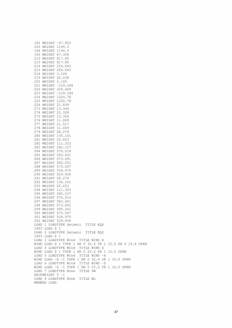
162 WEIGHT -97.903 163 WEIGHT 1144.3 164 WEIGHT 1144.3 165 WEIGHT 67.356 212 WEIGHT 817.85 213 WEIGHT 817.85 214 WEIGHT 256.043 215 WEIGHT 256.043 218 WEIGHT 3.105 219 WEIGHT 50.038 220 WEIGHT 3.105 221 WEIGHT -129.184 222 WEIGHT 329.409 223 WEIGHT -129.184 224 WEIGHT 1220.78 225 WEIGHT 1220.78 226 WEIGHT 21.839 273 WEIGHT 13.364 274 WEIGHT 23.328 275 WEIGHT 13.364 276 WEIGHT 11.069 277 WEIGHT 21.517 278 WEIGHT 11.069 279 WEIGHT 28.274 280 WEIGHT 130.101 281 WEIGHT 20.653 282 WEIGHT 111.323 283 WEIGHT 582.127 284 WEIGHT 570.514 285 WEIGHT 583.651 286 WEIGHT 573.691 287 WEIGHT 585.201 288 WEIGHT 575.567 289 WEIGHT 534.975 290 WEIGHT 529.936 291 WEIGHT 28.274 292 WEIGHT 130.101 293 WEIGHT 20.653 294 WEIGHT 111.323 295 WEIGHT 582.127 296 WEIGHT 570.514 297 WEIGHT 583.651 298 WEIGHT 573.691 299 WEIGHT 585.201 300 WEIGHT 575.567 301 WEIGHT 534.975 302 WEIGHT 529.936 LOAD 1 LOADTYPE Seismic TITLE EQX 1893 LOAD X 1 LOAD 2 LOADTYPE Seismic TITLE EQZ 1893 LOAD Z 1 LOAD 3 LOADTYPE Wind TITLE WIND X WIND LOAD X 1 TYPE 1 XR 0 32.4 YR 1 15.5 ZR 0 10.8 OPEN LOAD 4 LOADTYPE Wind TITLE WIND Z WIND LOAD Z 1 TYPE 1 XR 0 25.2 YR 1 15.5 OPEN LOAD 5 LOADTYPE Wind TITLE WIND -X WIND LOAD -X -1 TYPE 1 XR 0 32.4 YR 1 16.5 OPEN LOAD 6 LOADTYPE Wind TITLE WIND -Z WIND LOAD -Z -1 TYPE 1 XR 0 25.2 YR 1 16.5 OPEN LOAD 7 LOADTYPE None TITLE SW SELFWEIGHT Y -1 LOAD 8 LOADTYPE None TITLE WL MEMBER LOAD
47

4 7 TO 10 12 13 15 17 18 20 25 UNI GY -15 43 44 46 48 160 161 163 165 277 278 280 282 394 395 397 399 UNI GY -11 LOAD 9 LOADTYPE None TITLE SLAB DL + FLOOR FINISH FLOOR LOAD YRANGE 4.6 4.7 FLOAD -3.5 XRANGE 0 1.4 ZRANGE 7.65 9.25 GY YRANGE 4.6 4.7 FLOAD -3.5 XRANGE 7 8.4 ZRANGE 7.65 9.25 GY YRANGE 8.2 8.3 FLOAD -3.5 XRANGE 0 1.4 ZRANGE 7.65 9.25 GY YRANGE 8.2 8.3 FLOAD -3.5 XRANGE 7 8.4 ZRANGE 7.65 9.25 GY YRANGE 11.8 11.9 FLOAD -3.5 XRANGE 0 1.4 ZRANGE 7.65 9.25 GY YRANGE 11.8 11.9 FLOAD -3.5 XRANGE 7 8.4 ZRANGE 7.65 9.25 GY YRANGE 15.4 15.5 FLOAD -3.5 XRANGE 0 1.4 ZRANGE 7.65 9.25 GY YRANGE 15.4 15.5 FLOAD -3.5 XRANGE 7 8.4 ZRANGE 7.65 9.25 GY YRANGE 17.9 18 FLOAD -4 XRANGE 2.35 6.05 ZRANGE 7.65 9.25 LOAD 10 LOADTYPE None TITLE STAIR LOAD MEMBER LOAD 37 40 41 55 56 154 157 158 172 173 271 274 275 289 290 388 391 392 406 407 - 677 679 681 683 709 711 713 715 UNI GY -7.5 JOINT LOAD 273 TO 278 FY -0.5 LOAD 11 LOADTYPE None TITLE SLAB LL FLOOR LOAD YRANGE 4.6 4.7 FLOAD -3 XRANGE -8.4 16.8 ZRANGE 0 10.8 GY YRANGE 8.2 8.3 FLOAD -3 XRANGE -8.4 16.8 ZRANGE 0 10.8 GY YRANGE 11.8 11.9 FLOAD -3 XRANGE -8.4 16.8 ZRANGE 0 10.8 GY YRANGE 15.4 15.5 FLOAD -3 XRANGE -8.4 16.8 ZRANGE 0 10.8 GY YRANGE 17.9 18.1 FLOAD -1.5 GY LOAD COMB 12 1.5 * (DL+LL) 7 1.5 8 1.5 9 1.5 10 1.5 11 1.5 LOAD COMB 13 1.5 * (DL+EQX) 7 1.5 8 1.5 9 1.5 10 1.5 1 1.5 LOAD COMB 14 1.5 * (DL-EQX) 7 1.5 8 1.5 9 1.5 10 1.5 1 -1.5 LOAD COMB 15 1.5 * (DL+EQZ) 7 1.5 8 1.5 9 1.5 10 1.5 2 1.5 LOAD COMB 16 1.5 * (DL-EQZ) 7 1.5 8 1.5 9 1.5 10 1.5 2 -1.5 LOAD COMB 17 1.2 * (DL+LL+EQX) 7 1.2 8 1.2 9 1.2 10 1.2 11 1.2 1 1.2 LOAD COMB 18 1.2 * (DL+LL-EQX) 7 1.2 8 1.2 9 1.2 10 1.2 11 1.2 1 -1.2 LOAD COMB 19 1.2 * (DL+LL+EQZ) 7 1.2 8 1.2 9 1.2 10 1.2 11 1.2 2 1.2 LOAD COMB 20 1.2 * (DL+LL-EQZ) 7 1.2 8 1.2 9 1.2 10 1.2 11 1.2 1 -1.2 LOAD COMB 21 0.9 * DL + 1.5 * EQX 7 0.9 8 0.9 9 0.9 10 0.9 1 1.5 LOAD COMB 22 0.9 * DL - 1.5 * EQX 7 0.9 8 0.9 9 0.9 10 0.9 1 -1.5 LOAD COMB 23 0.9 * DL+ 1.5 * EQZ 7 0.9 8 0.9 9 0.9 10 0.9 2 1.5 LOAD COMB 24 0.9 * DL - 1.5 * EQZ 7 0.9 8 0.9 9 0.9 10 0.9 2 -1.5 LOAD COMB 25 1.5 * (DL+WX) 7 1.5 8 1.5 9 1.5 10 1.5 3 1.5 LOAD COMB 26 1.5 * (DL-WX) 7 1.5 8 1.5 9 1.5 10 1.5 5 -1.5 LOAD COMB 27 1.5 * (DL+WZ) 7 1.5 8 1.5 9 1.5 10 1.5 4 1.5 LOAD COMB 28 1.5 * (DL-WZ) 7 1.5 8 1.5 9 1.5 10 1.5 6 -1.5 LOAD COMB 29 1.2 * (DL+LL+WX) 7 1.2 8 1.2 9 1.2 10 1.2 11 1.2 3 1.2 LOAD COMB 30 1.2 * (DL+LL-WX)
48

7 1.2 8 1.2 9 1.2 10 1.2 11 1.2 5 -1.2 LOAD COMB 31 1.2 * (DL+LL+WZ) 7 1.2 8 1.2 9 1.2 10 1.2 11 1.2 4 1.2 LOAD COMB 32 1.2 * (DL+LL-WZ) 7 1.2 8 1.2 9 1.2 10 1.2 11 1.2 6 -1.2 LOAD COMB 33 0.9 * DL+ 1.5 * WX 7 0.9 8 0.9 9 0.9 10 0.9 3 1.5 LOAD COMB 34 0.9 * DL - 1.5 * WX 7 0.9 8 0.9 9 0.9 10 0.9 5 -1.5 LOAD COMB 35 0.9 * DL+ 1.5 * WZ 7 0.9 8 0.9 9 0.9 10 0.9 4 1.5 LOAD COMB 36 0.9 * DL - 1.5 * WZ 7 0.9 8 0.9 9 0.9 10 0.9 6 -1.5 PERFORM ANALYSIS PRINT ALL FINISH
49

STAAD INPUT FILE STAAD SPACE START JOB INFORMATION ENGINEER DATE 24-Dec-09 END JOB INFORMATION INPUT WIDTH 79 UNIT METER KN JOINT COORDINATES 1 0 -1.5 0; 2 10.69 -1.5 0; 3 0 1 0; 4 10.69 1 0; 5 0 -1.5 8.36; 6 10.69 -1.5 8.36; 7 0 1 8.36; 8 10.69 1 8.36; 9 0 -1.5 14.16; 10 10.69 -1.5 14.16; 11 0 1 14.16; 12 10.69 1 14.16; 13 0 -1.5 24.96; 14 10.69 -1.5 24.96; 15 0 1 24.96; 16 10.69 1 24.96; 17 5.345 1 0; 18 5.345 1 8.36; 19 5.345 1 14.16; 20 5.345 1 24.96; 27 5.345 -1.5 0; 28 5.345 -1.5 8.36; 29 5.345 -1.5 14.16; 31 0 4.6 0; 32 10.69 4.6 0; 33 0 4.6 8.36; 34 10.69 4.6 8.36; 35 0 4.6 14.16; 36 10.69 4.6 14.16; 37 0 4.6 24.96; 38 10.69 4.6 24.96; 39 5.345 4.6 0; 40 5.345 4.6 8.36; 41 5.345 4.6 14.16; 42 5.345 4.6 24.96; 46 0 4.6 4.18; 47 10.69 4.6 4.18; 48 5.345 4.6 4.18; 49 0 4.6 11.26; 50 10.69 4.6 11.26; 53 5.345 4.6 11.26; 58 0 8.2 0; 59 10.69 8.2 0; 60 0 8.2 8.36; 61 10.69 8.2 8.36; 62 0 8.2 14.16; 63 10.69 8.2 14.16; 64 0 8.2 24.96; 65 10.69 8.2 24.96; 66 5.345 8.2 0; 67 5.345 8.2 8.36; 68 5.345 8.2 14.16; 69 5.345 8.2 24.96; 73 0 8.2 4.18; 74 10.69 8.2 4.18; 75 5.345 8.2 4.18; 76 0 8.2 11.26; 77 10.69 8.2 11.26; 80 5.345 8.2 11.26; 85 0 11.8 0; 86 10.69 11.8 0; 87 0 11.8 8.36; 88 10.69 11.8 8.36; 89 0 11.8 14.16; 90 10.69 11.8 14.16; 91 0 11.8 24.96; 92 10.69 11.8 24.96; 93 5.345 11.8 0; 94 5.345 11.8 8.36; 95 5.345 11.8 14.16; 96 5.345 11.8 24.96; 100 0 11.8 4.18; 101 10.69 11.8 4.18; 102 5.345 11.8 4.18; 103 0 11.8 11.26; 104 10.69 11.8 11.26; 107 5.345 11.8 11.26; 112 0 15.4 0; 113 10.69 15.4 0; 114 0 15.4 8.36; 115 10.69 15.4 8.36; 116 0 15.4 14.16; 117 10.69 15.4 14.16; 118 0 15.4 24.96; 119 10.69 15.4 24.96; 120 5.345 15.4 0; 121 5.345 15.4 8.36; 122 5.345 15.4 14.16; 123 5.345 15.4 24.96; 127 0 15.4 4.18; 128 10.69 15.4 4.18; 129 5.345 15.4 4.18; 130 0 15.4 11.26; 131 10.69 15.4 11.26; 134 5.345 15.4 11.26; 139 0 4.6 17.76; 140 0 4.6 21.36; 141 10.69 4.6 17.76; 142 10.69 4.6 21.36; 143 5.345 4.6 17.76; 144 5.345 4.6 21.36; 145 0 8.2 17.76; 146 0 8.2 21.36; 147 5.345 8.2 17.76; 148 5.345 8.2 21.36; 149 10.69 8.2 17.76; 150 10.69 8.2 21.36; 151 0 15.4 17.76; 152 0 15.4 21.36; 153 5.345 15.4 17.76; 154 5.345 15.4 21.36; 155 10.69 15.4 17.76; 156 10.69 15.4 21.36; 157 0 11.8 17.76; 158 0 11.8 21.36; 159 5.345 11.8 17.76; 160 5.345 11.8 21.36; 161 10.69 11.8 17.76; 162 10.69 11.8 21.36; 163 0 1 35.76; 164 5.345 1 35.76; 165 0 -1.5 35.76; 166 10.69 -1.5 35.76; 167 10.69 1 35.76; 169 0 4.6 35.76; 170 5.345 4.6 35.76; 171 10.69 4.6 35.76; 172 0 8.2 35.76; 173 5.345 8.2 35.76; 174 10.69 8.2 35.76; 175 0 11.8 35.76; 176 5.345 11.8 35.76; 177 10.69 11.8 35.76; 178 0 15.4 35.76; 179 5.345 15.4 35.76; 180 10.69 15.4 35.76; 181 0 4.6 28.56; 182 10.69 4.6 28.56; 183 0 4.6 32.16; 184 10.69 4.6 32.16; 185 5.345 4.6 28.56; 186 5.345 4.6 32.16; 187 0 8.2 28.56; 188 5.345 8.2 28.56; 189 10.69 8.2 28.56; 190 0 8.2 32.16; 191 5.345 8.2 32.16; 192 10.69 8.2 32.16; 193 0 15.4 28.56; 194 5.345 15.4 28.56; 195 10.69 15.4 28.56; 196 0 15.4 32.16; 197 5.345 15.4 32.16; 198 10.69 15.4 32.16; 199 0 11.8 28.56; 200 5.345 11.8 28.56; 201 10.69 11.8 28.56; 202 0 11.8 32.16; 203 5.345 11.8 32.16; 204 10.69 11.8 32.16; MEMBER INCIDENCES 1 3 17; 2 1 3; 3 2 4; 5 5 7; 6 6 8; 8 9 11; 9 10 12; 10 15 20; 11 13 15; 12 14 16; 13 3 7; 14 4 8; 15 7 11; 16 8 12; 19 17 4; 22 20 16; 23 17 18; 24 18 19; 32 27 17; 33 28 18; 34 29 19; 36 31 39; 37 37 42; 38 31 46; 39 32 47; 40 33 49; 41 34 50; 44 39 32; 45 42 38; 46 39 48; 47 40 53; 52 3 31; 53 7 33; 54 11 35; 56 15 37; 58 16 38; 59 17 39; 60 4 32; 61 18 40; 62 19 41; 64 12 36; 66 8 34; 67 46 33; 68 47 34; 69 48 40; 70 46 48; 71 48 47; 72 33 40; 73 40 34; 74 35 41; 75 41 36; 78 49 35; 79 50 36; 82 53 41; 87 49 53; 88 53 50; 93 58 66; 94 64 69; 95 58 73; 96 59 74; 97 60 76; 98 61 77; 101 66 59; 102 69 65; 103 66 75; 104 67 80; 109 31 58; 110 33 60; 111 35 62; 113 37 64; 115 38 65; 116 39 66; 117 32 59; 118 40 67; 119 41 68; 121 36 63; 123 34 61; 124 73 60; 125 74 61; 126 75 67; 127 73 75; 128 75 74; 129 60 67; 130 67 61; 131 62 68;
50

132 68 63; 135 76 62; 136 77 63; 139 80 68; 144 76 80; 145 80 77; 150 85 93; 151 91 96; 152 85 100; 153 86 101; 154 87 103; 155 88 104; 158 93 86; 159 96 92; 160 93 102; 161 94 107; 166 58 85; 167 60 87; 168 62 89; 170 64 91; 172 65 92; 173 66 93; 174 59 86; 175 67 94; 176 68 95; 178 63 90; 180 61 88; 181 100 87; 182 101 88; 183 102 94; 184 100 102; 185 102 101; 186 87 94; 187 94 88; 188 89 95; 189 95 90; 192 103 89; 193 104 90; 196 107 95; 201 103 107; 202 107 104; 207 112 120; 208 118 123; 209 112 127; 210 113 128; 211 114 130; 212 115 131; 215 120 113; 216 123 119; 217 120 129; 218 121 134; 223 85 112; 224 87 114; 225 89 116; 227 91 118; 229 92 119; 230 93 120; 231 86 113; 232 94 121; 233 95 122; 235 90 117; 237 88 115; 238 127 114; 239 128 115; 240 129 121; 241 127 129; 242 129 128; 243 114 121; 244 121 115; 245 116 122; 246 122 117; 249 130 116; 250 131 117; 253 134 122; 258 130 134; 259 134 131; 265 11 15; 266 19 20; 267 12 16; 268 35 139; 269 36 141; 270 139 140; 271 140 37; 272 141 142; 273 142 38; 274 41 143; 275 143 144; 276 144 42; 277 139 143; 278 143 141; 279 140 144; 280 144 142; 281 62 145; 282 68 147; 283 63 149; 284 145 146; 285 146 64; 286 147 148; 287 148 69; 288 149 150; 289 150 65; 290 145 147; 291 147 149; 292 146 148; 293 148 150; 294 116 151; 295 122 153; 296 117 155; 297 151 152; 298 152 118; 299 153 154; 300 154 123; 301 155 156; 302 156 119; 303 151 153; 304 153 155; 305 152 154; 306 154 156; 307 89 157; 308 95 159; 309 90 161; 310 157 158; 311 158 91; 312 159 160; 313 160 96; 314 161 162; 315 162 92; 316 157 159; 317 159 161; 318 158 160; 319 160 162; 320 163 164; 321 165 163; 322 166 167; 323 164 167; 325 169 170; 326 170 171; 327 163 169; 328 167 171; 330 172 173; 331 173 174; 332 169 172; 333 171 174; 335 175 176; 336 176 177; 337 172 175; 338 174 177; 340 178 179; 341 179 180; 342 175 178; 343 177 180; 345 15 163; 346 20 164; 347 16 167; 348 37 181; 349 38 182; 350 181 183; 351 183 169; 352 182 184; 353 184 171; 354 42 185; 355 185 186; 356 186 170; 357 181 185; 358 185 182; 359 183 186; 360 186 184; 361 64 187; 362 69 188; 363 65 189; 364 187 190; 365 190 172; 366 188 191; 367 191 173; 368 189 192; 369 192 174; 370 187 188; 371 188 189; 372 190 191; 373 191 192; 374 118 193; 375 123 194; 376 119 195; 377 193 196; 378 196 178; 379 194 197; 380 197 179; 381 195 198; 382 198 180; 383 193 194; 384 194 195; 385 196 197; 386 197 198; 387 91 199; 388 96 200; 389 92 201; 390 199 202; 391 202 175; 392 200 203; 393 203 176; 394 201 204; 395 204 177; 396 199 200; 397 200 201; 398 202 203; 399 203 204; DEFINE MATERIAL START ISOTROPIC CONCRETE E 2.17185e+007 POISSON 0.17 DENSITY 23.5616 ALPHA 1e-005 DAMP 0.05 END DEFINE MATERIAL MEMBER PROPERTY AMERICAN 2 5 6 8 9 32 TO 34 52 TO 54 59 61 62 64 66 109 TO 111 116 118 119 121 123 - 166 TO 168 173 175 176 178 180 223 TO 225 230 232 233 235 - 237 PRIS YD 0.3 ZD 0.6 1 10 13 TO 16 19 22 TO 24 265 TO 267 320 323 345 TO 347 PRIS YD 0.6 ZD 0.23 36 38 TO 41 44 46 47 67 TO 75 78 79 82 87 88 93 95 TO 98 101 103 104 - 124 TO 132 135 136 139 144 145 150 152 TO 155 158 160 161 181 TO 189 192 - 193 196 201 202 207 209 TO 212 215 217 218 238 TO 246 249 250 253 258 259 - 268 TO 319 325 326 330 331 335 336 340 341 348 TO 399 PRIS YD 0.5 ZD 0.2 MEMBER PROPERTY AMERICAN 3 60 117 174 231 PRIS YD 0.5 ZD 0.35 MEMBER PROPERTY AMERICAN 321 322 327 328 332 333 337 338 342 343 PRIS YD 0.3 ZD 0.4 MEMBER PROPERTY AMERICAN 11 12 56 58 113 115 170 172 227 229 PRIS YD 0.3 ZD 0.8 37 45 94 102 151 159 208 216 PRIS YD 0.8 ZD 0.3 CONSTANTS MATERIAL CONCRETE ALL SUPPORTS 1 2 5 6 9 10 13 14 27 TO 29 165 166 FIXED DEFINE WIND LOAD
51
TYPE 1 INT 1.73 1.73 1.73 1.73 1.73 HEIG 1 4.6 8.2 11.8 15.4 EXP 1 JOINT 3 7 11 15 31 33 35 37 46 49 58 60 62 64 73 76 85 87 89 91 100 - 103 112 114 116 118 127 130 163 169 172 175 178 DEFINE 1893 LOAD ZONE 0.24 RF 3 I 1.5 SS 1 DM 0.05 DT 2.5 JOINT WEIGHT 1 WEIGHT 7.952 2 WEIGHT 7.952 3 WEIGHT 53.408 4 WEIGHT 53.408 5 WEIGHT 7.952 6 WEIGHT 7.952 7 WEIGHT 53.194 8 WEIGHT 53.194 9 13 165 WEIGHT 7.952 10 14 166 WEIGHT 7.952 11 15 163 WEIGHT 47.303 12 16 167 WEIGHT 47.303 13 165 WEIGHT 7.952 14 166 WEIGHT 7.952 15 163 WEIGHT 45.876 16 167 WEIGHT 45.876 17 WEIGHT 66.125 18 WEIGHT 51.662 19 20 164 WEIGHT 48.306 20 164 WEIGHT 59.869 27 WEIGHT 7.952 28 WEIGHT 7.952 29 WEIGHT 7.952 31 WEIGHT 252.101 32 WEIGHT 252.101 33 WEIGHT 376.928 34 WEIGHT 376.928 35 37 169 WEIGHT 291.626 36 38 171 WEIGHT 291.626 37 169 WEIGHT 174.935 38 171 WEIGHT 174.935 39 WEIGHT 490.059 40 WEIGHT 758.125 41 42 170 WEIGHT 612.534 42 170 WEIGHT 358.009 58 WEIGHT 253.526 59 WEIGHT 253.526 60 WEIGHT 378.061 61 WEIGHT 378.061 62 64 172 WEIGHT 294.235 63 65 174 WEIGHT 294.235 64 172 WEIGHT 176.371 65 174 WEIGHT 176.371 66 WEIGHT 488.438 67 WEIGHT 752.137 68 69 173 WEIGHT 609.883 69 173 WEIGHT 357.115 85 WEIGHT 254.713 86 WEIGHT 254.713 87 WEIGHT 377.672 88 WEIGHT 377.672 89 91 175 WEIGHT 296.117 90 92 177 WEIGHT 296.117 91 175 WEIGHT 177.533 92 177 WEIGHT 177.533 93 WEIGHT 488.047
52

94 WEIGHT 748.027 95 96 176 WEIGHT 609.754 96 176 WEIGHT 357.041 112 WEIGHT 235.221 113 WEIGHT 235.221 114 WEIGHT 365.165 115 WEIGHT 365.165 116 118 178 WEIGHT 271.823 117 119 180 WEIGHT 271.823 118 178 WEIGHT 158.023 119 180 WEIGHT 158.023 120 WEIGHT 482.725 121 WEIGHT 765.329 122 123 179 WEIGHT 604.806 123 179 WEIGHT 348.624 LOAD 1 LOADTYPE Seismic TITLE EQX 1893 LOAD X 1 LOAD 2 LOADTYPE Seismic TITLE EQZ 1893 LOAD Z 1 LOAD 3 LOADTYPE Wind TITLE WIND X WIND LOAD X 1 TYPE 1 XR 0 32.4 YR 1 16.5 OPEN LOAD 4 LOADTYPE Wind TITLE WIND Z WIND LOAD Z 1 TYPE 1 XR 0 25.2 YR 3.3 16.5 OPEN LOAD 5 LOADTYPE Wind TITLE WIND -X WIND LOAD -X -1 TYPE 1 XR 0 32.4 YR 3.3 16.5 OPEN LOAD 6 LOADTYPE Wind TITLE WIND -Z WIND LOAD -Z -1 TYPE 1 XR 0 25.2 YR 3.3 16.5 OPEN LOAD 7 LOADTYPE None TITLE SW SELFWEIGHT Y -1 LOAD 8 LOADTYPE None TITLE WALL MEMBER LOAD 36 TO 41 44 TO 47 67 TO 69 78 79 82 93 TO 98 101 TO 104 124 TO 126 135 136 - 139 150 TO 155 158 TO 161 181 TO 183 192 193 196 207 TO 212 215 TO 218 238 - 239 TO 240 249 250 253 325 326 330 331 335 336 340 341 UNI GY -5 LOAD 9 LOADTYPE None TITLE SLAB DL FLOOR LOAD YRANGE 4.6 4.8 FLOAD -4.8 GY YRANGE 8.2 8.3 FLOAD -4.8 GY YRANGE 11.8 11.9 FLOAD -4.8 GY YRANGE 15.4 15.5 FLOAD -4.8 GY LOAD 10 LOADTYPE None TITLE FLOOR FINISH FLOOR LOAD YRANGE 4.6 4.8 FLOAD -1 GY YRANGE 8.2 8.3 FLOAD -1 GY YRANGE 11.8 11.9 FLOAD -1 GY YRANGE 15.4 15.5 FLOAD -1 GY LOAD 11 LOADTYPE None TITLE SLAB LL FLOOR LOAD YRANGE 4.6 4.8 FLOAD -4 GY YRANGE 8.2 8.3 FLOAD -4 GY YRANGE 11.8 11.9 FLOAD -4 GY YRANGE 15.4 15.5 FLOAD -4 GY LOAD COMB 12 1.5 * (DL+LL) 7 1.5 8 1.5 9 1.5 10 1.5 11 1.5 LOAD COMB 13 1.5 * (DL+EQX) 7 1.5 8 1.5 9 1.5 10 1.5 1 1.5 LOAD COMB 14 1.5 * (DL-EQX) 7 1.5 8 1.5 9 1.5 10 1.5 1 -1.5 LOAD COMB 15 1.5 * (DL+EQZ) 7 1.5 8 1.5 9 1.5 10 1.5 2 1.5 LOAD COMB 16 1.5 * (DL-EQZ) 7 1.5 8 1.5 9 1.5 10 1.5 2 -1.5 LOAD COMB 17 1.2 * (DL+LL+EQX)
53

7 1.2 8 1.2 9 1.2 10 1.2 11 1.2 1 1.2 LOAD COMB 18 1.2 * (DL+LL-EQX) 7 1.2 8 1.2 9 1.2 10 1.2 11 1.2 1 -1.2 LOAD COMB 19 1.2 * (DL+LL+EQZ) 7 1.2 8 1.2 9 1.2 10 1.2 11 1.2 2 1.2 LOAD COMB 20 1.2 * (DL+LL-EQZ) 7 1.2 8 1.2 9 1.2 10 1.2 11 1.2 1 -1.2 LOAD COMB 21 0.9 * DL + 1.5 * EQX 7 0.9 8 0.9 9 0.9 10 0.9 1 1.5 LOAD COMB 22 0.9 * DL - 1.5 * EQX 7 0.9 8 0.9 9 0.9 10 0.9 1 -1.5 LOAD COMB 23 0.9 * DL+ 1.5 * EQZ 7 0.9 8 0.9 9 0.9 10 0.9 2 1.5 LOAD COMB 24 0.9 * DL - 1.5 * EQZ 7 0.9 8 0.9 9 0.9 10 0.9 2 -1.5 LOAD COMB 25 1.5 * (DL+WX) 7 1.5 8 1.5 9 1.5 10 1.5 3 1.5 LOAD COMB 26 1.5 * (DL-WX) 7 1.5 8 1.5 9 1.5 10 1.5 5 -1.5 LOAD COMB 27 1.5 * (DL+WZ) 7 1.5 8 1.5 9 1.5 10 1.5 4 1.5 LOAD COMB 28 1.5 * (DL-WZ) 7 1.5 8 1.5 9 1.5 10 1.5 6 -1.5 LOAD COMB 29 1.2 * (DL+LL+WX) 7 1.2 8 1.2 9 1.2 10 1.2 11 1.2 3 1.2 LOAD COMB 30 1.2 * (DL+LL-WX) 7 1.2 8 1.2 9 1.2 10 1.2 11 1.2 5 -1.2 LOAD COMB 31 1.2 * (DL+LL+WZ) 7 1.2 8 1.2 9 1.2 10 1.2 11 1.2 4 1.2 LOAD COMB 32 1.2 * (DL+LL-WZ) 7 1.2 8 1.2 9 1.2 10 1.2 11 1.2 6 -1.2 LOAD COMB 33 0.9 * DL+ 1.5 * WX 7 0.9 8 0.9 9 0.9 10 0.9 3 1.5 LOAD COMB 34 0.9 * DL - 1.5 * WX 7 0.9 8 0.9 9 0.9 10 0.9 5 -1.5 LOAD COMB 35 0.9 * DL+ 1.5 * WZ 7 0.9 8 0.9 9 0.9 10 0.9 4 1.5 LOAD COMB 36 0.9 * DL - 1.5 * WZ 7 0.9 8 0.9 9 0.9 10 0.9 6 -1.5 PERFORM ANALYSIS PRINT ALL FINISH
54

Design Summary For Multi Level ParkingFooting
Footing No Axial Load Length Breadth d D L
F2 Pu = 3200 2900 3400 600 1340 200 20 @ 100 c/c 20 @ 100 c/cF3 Pu = 3000 3000 3300 700 1400 200 20 @ 100 c/c 20 @ 100 c/cF4 Pu = 1200 2000 2100 300 660 200 16 @ 120 c/c 16 @ 120 c/cF5 Pu = 2000 2500 2700 400 940 200 16 @ 100 c/c 16 @ 100 c/cF6 Pu = 3220 3000 3500 600 1300 200 20 @ 100 c/c 20 @ 100 c/cF7 Pu = 9860 5700 5700 1300 2600 200 25 @ 100 c/c 25 @ 100 c/c
Combined Footing
Footing No Axial Load Length Breadth d D LCF1 Pu = 4000 3900 5200 1100 2200 - 16 @ 100 c/c 16 @ 100 c/cCF2 Pu = 9620 5100 6300 1300 2600 - 25 @ 100 c/c 25 @ 100 c/cCF3 Pu = 2400 2700 3000 400 870 - 16 @ 100 c/c 16 @ 100 c/cCF4 Pu = 5400, 2100 7000 4500 - 700 - 12 @ 150 c/c 12 @ 150 c/cCF5 Pu = 9600, 6400 7000 7000 1100 - 12 @ 150 c/c 12 @ 150 c/cCF6 Pu = 6800, 10200 10500 9000 1000 12 @ 150 c/c 12 @ 150 c/cCF7 Pu = 9860, 3000 8000 5700 900 12 @ 150 c/c 12 @ 150 c/cCF8 Pu = 9600, 6400 7000 7000 1600 12 @ 150 c/c 12 @ 150 c/cCF9 Pu = 9860 6500 7800 900 12 @ 150 c/c 12 @ 150 c/c
CF10 Pu = 9860 8000 6400 900 12 @ 150 c/c 12 @ 150 c/c
ColumnsColumn No Load Case Axial Force Moment X Moment Y Size of column Reinforcement Stirrups
C1 1.5(DL+EQX) 374.77 223.8 140.15 230 x 230 6 of 20 8 @ 200 c/cC1a 1.5(DL+EQX) 1307.33 340.03 769.88 400 x 800 12 of 25 8 @ 200 c/cC2 1.5(DL+EQX) 925 334 228.15 350 x 800 12 of 25 8 @ 200 c/cC3 1.2(DL+LL-EQX) 366.32 169.29 353.51 300 x 600 12 of 25 8 @ 200 c/cC4 1.5(DL-EQX) 226.3 138.53 192.01 350 x 500 12 of 25 8 @ 200 c/cC5 1.2(DL+LL-EQX) 830.8 59.63 224.86 350 x 600 10 of 25 8 @ 200 c/cC6 1.5(DL-EQX) 560.34 563.33 210.34 400 x 900 16 of 25 8 @ 200 c/cC7 1.5(DL-EQX) 4861.814 1817.69 0.23 800 x 800 30 of 32 8 @ 200 c/cC8 1.5(DL-EQX) 895 324 240.15 300 x 800 12 of 25 8 @ 200 c/cC9 1.5(DL+EQX) 717.13 112.72 60.37 300 x 400 8 of 25 8 @ 200 c/cC3 1.2(DL+LL-EQX) 366.32 169.29 353.51 300 x 600 12 of 25 8 @ 200 c/c
C10 1.5(DL-EQX) 3015.88 918.44 2 550 x 850 22 of 25 8 @ 200 c/c
Plinth Beams
Beam No Load Case B D Ast Top Ast Bottom Shear RftSupport Midspan Support Midspan
PB1 1.5(DL-EQX) 380 127 152 151 250 600 6 of 25 4 of 25 8 @ 200
Reinforcement
Reinforcement
Moments Shear
55

SLABThickness
GF,FF,SF,TF 120
GF,FF,SF,TF Roof Beams for 8.36 & 5.5Beam No Load Case B D Ast Top Ast Bottom Shear Rft Legs
Support Midspan Support MidspanB-1 1.5(DL+EQX) 1053 331 150 233 218 400 900 12 of 25 5 of 25 12 @ 150 4B-2 1.5(DL-EQX) 2065 855 125 908 884 800 900 18 of 25 8 of 25 12 @ 150 4
B-2A 1.5(DL-EQX) 1428 746 163 199 184 550 900 14 of 25 8 of 25 12 @ 150 2B-3 1.5(DL-EQZ) 672 303 11 60 47 300 900 6 of 25 5 of 25 8 @ 200 4B-4 1.5(DL-EQZ) 350 900 6 of 25 5 of 25 12 @ 150 2B-5 1.5(DL-EQZ) 350 900 6 of 25 4 of 25 12 @ 150 2B-6 1.5(DL+EQZ) 137 58 12 60 51 250 550 4 of 20 2of 20 8 @ 200 2B-7 1.5(DL+EQX) 196 102 5 25 18 250 550 6 of 20 3 of 20 8 @ 200 2
SLAB RampThickness
GF,FF,SF,TF 150
GF,FF,SF,TF Roof Beams for 8.36 & 5.5Beam No Load Case B D Ast Top Ast Bottom Shear Rft Legs
Support Midspan Support MidspanRB1 1.5(DL+EQX) 235 150 0 125 120 300 500 4 of 25 2 of 25+1 of 20 12 @ 150 2RB2 1.5(DL-EQX) 325 190 0 70 165 300 400 2 of 25 + 1 of 20 3 of 25+1 of 20 12 @ 150 2RB3 1.5(DL-EQX) 803 360 0 377 270 300 850 8 of 25 3 of 25 12 @ 150 2RB4 1.5(DL-EQZ) 283 120 0 90 139 300 600 4 of 25 3 of 25 8 @ 200 2
Torsion
706 314 20
Rft12 @ 150 c/c
Rft12 @ 150 c/c
Moments
MomentsTorsion
Shear
282 259
Shear
56
DESIGN OF FOOTING

DESIGN OF ISOLATED FOOTING F2
Design Parameters
Maximum factored axial load coming on footing = 3200 kNSafe Bearing capacity of the soil = 225 kN/ m2
Grade of Concrete M30Grade of Steel Fe415Characteristic compressive strength of concrete , fck ( N/mm2 ) 30Characteristic yield strength of steel , fy ( N/mm2 ) 415Unit weight of concrete , γc ( kN/m3 ) 24Partial safety factor for concrete 1.5Nominal Cover to exposure condition( mm ) 50Diameter of bars (mm) 20
Column DimensionsBreadth of the column (mm) B = 300Depth of the column (mm) D = 800
Design
Maximum axial load coming on footing = 2000.00 kNAdd 10% toward the self-weight of footing = 200.00 kN
Total load = 2200.00 kNSBC of Soil : 225 kN/m2 is considered in the design of foundations.
Area of footing required = 2200 / 225= 9.778 m2
L = 3.39 mB = 2.89 m
Provide footing of size 3.4 m x 2.9 m
Projection beyond Column Faces = 1.29 mNet Upward Pressure on the foundation = 306.812 kN/m2
B.M @ Section XX = Mx = 869.30 kNmFactored Moment = Mux = 1303.95 kNm
Equating Mu,lim to Mux = 0.138fckbd^2 = MuxMu,lim = 3312 d^2
627 mm
B.M @ Section YY = My = 741 kNmFactored Moment = Muy = 1111 kNm
Equating Mu,lim to Muy = 0.138fckbd^2 = MuyMu,lim = 1242 d^2
946 mm
Effective cover to lower layer of steel = 50 mm + 10 mm = 60 mm Effective cover to upper layer of steel = 60 mm + 20 mm = 80 mm Overall depth required = 946 mm + 80 mm = 1026 mm
The overall depth may be increased by 30% to limit the shear stress
Overall depth reqd = 1340 mm
57

Effective depth for short span = 1340 mm - 60 mm = 1280 mm Effective depth for long span = 1340 mm - 80 mm = 1260 mm
Steel Reqd for Longer Direction
Muy / bd^2 = 2.334% of steel = 0.718 %
Area of steel required = 2714 mm2
Provide 9 bars of 20 mm dia Spacing of 20 mm dia bars 115 mm c/c
Steel Reqd for Shorter Direction
Mux / bd^2 = 0.995% of steel = 0.287 %
Area of steel required = 2940 mm2
Reinforcment Reqd for central band of 3.19 m = 2183 mm2
Provide 9 bars of 20 mm dia Spacing of 20 mm dia bars 143 mm c/c
Check For Shear
Shear force at this critical section X1 X1
V = 14 kNFactored Shear Vu = 21 kN
Overall depth of the critical section D' = 608 mmEffective deph of the critical section d' = 548 mm
Breadth of the footing @ tp @this critical section b' = 3360 mmNominal shear stress τυ = 0.01 N/mm2
Percentage of steel provided = 0.15 %Permissible punching shear stress = 0.25 x sqrt(fck)
1.37 N/mm2 > 0.01 N/mm2
Provided Section is adequate.
Critical section X1 X1 is considered at a distance equal to the effective depth from the face of the column, i.e at a distance of 1280 mm from the face of the column
58

DESIGN OF ISOLATED FOOTING F3
Design Parameters
Maximum factored axial load coming on footing = 3000 kNSafe Bearing capacity of the soil = 225 kN/ m2
Grade of Concrete M30Grade of Steel Fe415Characteristic compressive strength of concrete , fck ( N/mm2 ) 30Characteristic yield strength of steel , fy ( N/mm2 ) 415Unit weight of concrete , γc ( kN/m3 ) 24Partial safety factor for concrete 1.5Nominal Cover to exposure condition( mm ) 50Diameter of bars (mm) 20
Column DimensionsBreadth of the column (mm) B = 300Depth of the column (mm) D = 600
Design
Maximum axial load coming on footing = 2000.00 kNAdd 10% toward the self-weight of footing = 200.00 kN
Total load = 2200.00 kNSBC of Soil : 225 kN/m2 is considered in the design of foundations.
Area of footing required = 2200 / 225= 9.778 m2
L = 3.28 mB = 2.98 m
Provide footing of size 3.3 m x 3 m
Projection beyond Column Faces = 1.34 mNet Upward Pressure on the foundation = 306.812 kN/m2
B.M @ Section XX = Mx = 904.04 kNmFactored Moment = Mux = 1356.06 kNm
Equating Mu,lim to Mux = 0.138fckbd^2 = MuxMu,lim = 2484 d^2
739 mm
B.M @ Section YY = My = 821 kNmFactored Moment = Muy = 1232 kNm
Equating Mu,lim to Muy = 0.138fckbd^2 = MuyMu,lim = 1242 d^2
996 mm
Effective cover to lower layer of steel = 50 mm + 10 mm = 60 mm Effective cover to upper layer of steel = 60 mm + 20 mm = 80 mm Overall depth required = 996 mm + 80 mm = 1076 mm
The overall depth may be increased by 30% to limit the shear stress
Overall depth reqd = 1400 mm
59

Effective depth for short span = 1400 mm - 60 mm = 1340 mm Effective depth for long span = 1400 mm - 80 mm = 1320 mm
Steel Reqd for Longer Direction
Muy / bd^2 = 2.357% of steel = 0.726 %
Area of steel required = 2875 mm2
Provide 10 bars of 20 mm dia Spacing of 20 mm dia bars 109 mm c/c
Steel Reqd for Shorter Direction
Mux / bd^2 = 1.259% of steel = 0.367 %
Area of steel required = 2954 mm2
Reinforcment Reqd for central band of 3.08 m = 2238 mm2
Provide 10 bars of 20 mm dia Spacing of 20 mm dia bars 140 mm c/c
Check For Shear
Shear force at this critical section X1 X1
V = 0 kNFactored Shear Vu = 0 kN
Overall depth of the critical section D' = 700 mmEffective deph of the critical section d' = 640 mm
Breadth of the footing @ tp @this critical section b' = 3280 mmNominal shear stress τυ = 0.00 N/mm2
Percentage of steel provided = 0.15 %Permissible punching shear stress = 0.25 x sqrt(fck)
1.37 N/mm2 > 0.00 N/mm2
Provided Section is adequate.
Critical section X1 X1 is considered at a distance equal to the effective depth from the face of the column, i.e at a distance of 1340 mm from the face of the column
60
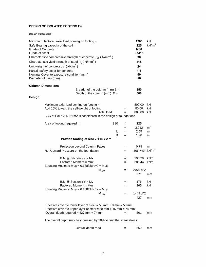
DESIGN OF ISOLATED FOOTING F4
Design Parameters
Maximum factored axial load coming on footing = 1200 kNSafe Bearing capacity of the soil = 225 kN/ m2
Grade of Concrete M30Grade of Steel Fe415Characteristic compressive strength of concrete , fck ( N/mm2 ) 30Characteristic yield strength of steel , fy ( N/mm2 ) 415Unit weight of concrete , γc ( kN/m3 ) 24Partial safety factor for concrete 1.5Nominal Cover to exposure condition( mm ) 50Diameter of bars (mm) 16
Column DimensionsBreadth of the column (mm) B = 350Depth of the column (mm) D = 500
Design
Maximum axial load coming on footing = 800.00 kNAdd 10% toward the self-weight of footing = 80.00 kN
Total load = 880.00 kNSBC of Soil : 225 kN/m2 is considered in the design of foundations.
Area of footing required = 880 / 225= 3.912 m2
L = 2.05 mB = 1.90 m
Provide footing of size 2.1 m x 2 m
Projection beyond Column Faces = 0.78 mNet Upward Pressure on the foundation = 306.749 kN/m2
B.M @ Section XX = Mx = 190.29 kNmFactored Moment = Mux = 285.44 kNm
Equating Mu,lim to Mux = 0.138fckbd^2 = MuxMu,lim = 2070 d^2
371 mm
B.M @ Section YY = My = 176 kNmFactored Moment = Muy = 265 kNm
Equating Mu,lim to Muy = 0.138fckbd^2 = MuyMu,lim = 1449 d^2
427 mm
Effective cover to lower layer of steel = 50 mm + 8 mm = 58 mm Effective cover to upper layer of steel = 58 mm + 16 mm = 74 mm Overall depth required = 427 mm + 74 mm = 501 mm
The overall depth may be increased by 30% to limit the shear stress
Overall depth reqd = 660 mm
61

Effective depth for short span = 660 mm - 58 mm = 602 mm Effective depth for long span = 660 mm - 74 mm = 586 mm
Steel Reqd for Longer Direction
Muy / bd^2 = 2.202% of steel = 0.673 %
Area of steel required = 1380 mm2
Provide 7 bars of 16 mm dia Spacing of 16 mm dia bars 145 mm c/c
Steel Reqd for Shorter Direction
Mux / bd^2 = 1.575% of steel = 0.467 %
Area of steel required = 1405 mm2
Reinforcment Reqd for central band of 1.85 m = 1386 mm2
Provide 9 bars of 16 mm dia Spacing of 16 mm dia bars 145 mm c/c
Check For Shear
Shear force at this critical section X1 X1
V = 110 kNFactored Shear Vu = 166 kN
Overall depth of the critical section D' = 381 mmEffective deph of the critical section d' = 323 mm
Breadth of the footing @ tp @this critical section b' = 1704 mmNominal shear stress τυ = 0.30 N/mm2
Percentage of steel provided = 0.33 %Permissible punching shear stress = 0.25 x sqrt(fck)
1.37 N/mm2 > 0.30 N/mm2
Provided Section is adequate.
Critical section X1 X1 is considered at a distance equal to the effective depth from theface of the column, i.e at a distance of 602 mm from the face of the column
62

DESIGN OF ISOLATED FOOTING F5
Design Parameters
Maximum factored axial load coming on footing = 2000 kNSafe Bearing capacity of the soil = 225 kN/ m2
Grade of Concrete M30Grade of Steel Fe415Characteristic compressive strength of concrete , fck ( N/mm2 ) 30Characteristic yield strength of steel , fy ( N/mm2 ) 415Unit weight of concrete , γc ( kN/m3 ) 24Partial safety factor for concrete 1.5Nominal Cover to exposure condition( mm ) 50Diameter of bars (mm) 16
Column DimensionsBreadth of the column (mm) B = 350Depth of the column (mm) D = 600
Design
Maximum axial load coming on footing = 1333.33 kNAdd 10% toward the self-weight of footing = 133.33 kN
Total load = 1466.67 kNSBC of Soil : 225 kN/m2 is considered in the design of foundations.
Area of footing required = 1466.67 / 225= 6.519 m2
L = 2.68 mB = 2.43 m
Provide footing of size 2.7 m x 2.5 m
Projection beyond Column Faces = 1.04 mNet Upward Pressure on the foundation = 306.796 kN/m2
B.M @ Section XX = Mx = 445.42 kNmFactored Moment = Mux = 668.13 kNm
Equating Mu,lim to Mux = 0.138fckbd^2 = MuxMu,lim = 2484 d^2
519 mm
B.M @ Section YY = My = 404 kNmFactored Moment = Muy = 606 kNm
Equating Mu,lim to Muy = 0.138fckbd^2 = MuyMu,lim = 1449 d^2
647 mm
Effective cover to lower layer of steel = 50 mm + 8 mm = 58 mm Effective cover to upper layer of steel = 58 mm + 16 mm = 74 mm Overall depth required = 647 mm + 74 mm = 721 mm
The overall depth may be increased by 30% to limit the shear stress
Overall depth reqd = 940 mm
63

Effective depth for short span = 940 mm - 58 mm = 882 mm Effective depth for long span = 940 mm - 74 mm = 866 mm
Steel Reqd for Longer Direction
Muy / bd^2 = 2.308% of steel = 0.709 %
Area of steel required = 2149 mm2
Provide 11 bars of 16 mm dia Spacing of 16 mm dia bars 100 mm c/c
Steel Reqd for Shorter Direction
Mux / bd^2 = 1.431% of steel = 0.421 %
Area of steel required = 2229 mm2
Reinforcment Reqd for central band of 2.48 m = 1905 mm2
Provide 12 bars of 16 mm dia Spacing of 16 mm dia bars 105 mm c/c
Check For Shear
Shear force at this critical section X1 X1
V = 131 kNFactored Shear Vu = 196 kN
Overall depth of the critical section D' = 482 mmEffective deph of the critical section d' = 424 mm
Breadth of the footing @ tp @this critical section b' = 2364 mmNominal shear stress τυ = 0.20 N/mm2
Percentage of steel provided = 0.24 %Permissible punching shear stress = 0.25 x sqrt(fck)
1.37 N/mm2 > 0.20 N/mm2
Provided Section is adequate.
Critical section X1 X1 is considered at a distance equal to the effective depth from the face of the column, i.e at a distance of 882 mm from the face of the column
64

DESIGN OF ISOLATED FOOTING F6
Design Parameters
Maximum factored axial load coming on footing = 3220 kNSafe Bearing capacity of the soil = 225 kN/ m2
Grade of Concrete M30Grade of Steel Fe415Characteristic compressive strength of concrete , fck ( N/mm2 ) 30Characteristic yield strength of steel , fy ( N/mm2 ) 415Unit weight of concrete , γc ( kN/m3 ) 24Partial safety factor for concrete 1.5Nominal Cover to exposure condition( mm ) 50Diameter of bars (mm) 20
Column DimensionsBreadth of the column (mm) B = 400Depth of the column (mm) D = 900
Design
Maximum axial load coming on footing = 2146.67 kNAdd 10% toward the self-weight of footing = 214.67 kN
Total load = 2361.34 kNSBC of Soil : 225 kN/m2 is considered in the design of foundations.
Area of footing required = 2361.34 / 225= 10.495 m2
L = 3.50 mB = 3.00 m
Provide footing of size 3.5 m x 3 m
Projection beyond Column Faces = 1.30 mNet Upward Pressure on the foundation = 306.813 kN/m2
B.M @ Section XX = Mx = 906.66 kNmFactored Moment = Mux = 1359.99 kNm
Equating Mu,lim to Mux = 0.138fckbd^2 = MuxMu,lim = 3726 d^2
604 mm
B.M @ Section YY = My = 777 kNmFactored Moment = Muy = 1166 kNm
Equating Mu,lim to Muy = 0.138fckbd^2 = MuyMu,lim = 1656 d^2
839 mm
Effective cover to lower layer of steel = 50 mm + 10 mm = 60 mm Effective cover to upper layer of steel = 60 mm + 20 mm = 80 mm Overall depth required = 839 mm + 80 mm = 919 mm
The overall depth may be increased by 30% to limit the shear stress
Overall depth reqd = 1300 mm
65
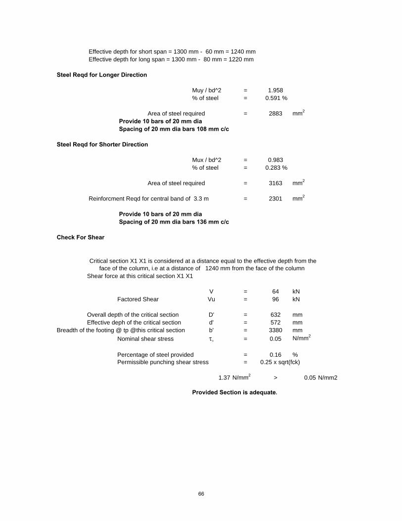
Effective depth for short span = 1300 mm - 60 mm = 1240 mm Effective depth for long span = 1300 mm - 80 mm = 1220 mm
Steel Reqd for Longer Direction
Muy / bd^2 = 1.958% of steel = 0.591 %
Area of steel required = 2883 mm2
Provide 10 bars of 20 mm dia Spacing of 20 mm dia bars 108 mm c/c
Steel Reqd for Shorter Direction
Mux / bd^2 = 0.983% of steel = 0.283 %
Area of steel required = 3163 mm2
Reinforcment Reqd for central band of 3.3 m = 2301 mm2
Provide 10 bars of 20 mm dia Spacing of 20 mm dia bars 136 mm c/c
Check For Shear
Shear force at this critical section X1 X1
V = 64 kNFactored Shear Vu = 96 kN
Overall depth of the critical section D' = 632 mmEffective deph of the critical section d' = 572 mm
Breadth of the footing @ tp @this critical section b' = 3380 mmNominal shear stress τυ = 0.05 N/mm2
Percentage of steel provided = 0.16 %Permissible punching shear stress = 0.25 x sqrt(fck)
1.37 N/mm2 > 0.05 N/mm2
Provided Section is adequate.
Critical section X1 X1 is considered at a distance equal to the effective depth from the face of the column, i.e at a distance of 1240 mm from the face of the column
66

DESIGN OF ISOLATED FOOTING F7
Design Parameters
Maximum factored axial load coming on footing = 9860 kNSafe Bearing capacity of the soil = 225 kN/ m2
Grade of Concrete M30Grade of Steel Fe415Characteristic compressive strength of concrete , fck ( N/mm2 ) 30Characteristic yield strength of steel , fy ( N/mm2 ) 415Unit weight of concrete , γc ( kN/m3 ) 24Partial safety factor for concrete 1.5Nominal Cover to exposure condition( mm ) 50Diameter of bars (mm) 25
Column DimensionsBreadth of the column (mm) B = 800Depth of the column (mm) D = 800
Design
Maximum axial load coming on footing = 6573.33 kNAdd 10% toward the self-weight of footing = 657.33 kN
Total load = 7230.67 kNSBC of Soil : 225 kN/m2 is considered in the design of foundations.
Area of footing required = 7230.67 / 225= 32.137 m2
L = 5.67 mB = 5.67 m
Provide footing of size 5.7 m x 5.7 m
Projection beyond Column Faces = 2.43 mNet Upward Pressure on the foundation = 306.812 kN/m2
B.M @ Section XX = Mx = 5154.13 kNmFactored Moment = Mux = 7731.20 kNm
Equating Mu,lim to Mux = 0.138fckbd^2 = MuxMu,lim = 3312 d^2
1528 mm
B.M @ Section YY = My = 5154 kNmFactored Moment = Muy = 7731 kNm
Equating Mu,lim to Muy = 0.138fckbd^2 = MuyMu,lim = 3312 d^2
1528 mm
Effective cover to lower layer of steel = 50 mm + 12.5 mm = 62.5 mm Effective cover to upper layer of steel = 62.5 mm + 25 mm = 87.5 mm Overall depth required = 1528 mm + 87.5 mm = 1615 mm
The overall depth may be increased by 30% to limit the shear stress
Overall depth reqd = 2600 mm
67

Effective depth for short span = 2600 mm - 62.5 mm = 2537.5 mm Effective depth for long span = 2600 mm - 87.5 mm = 2512.5 mm
Steel Reqd for Longer Direction
Muy / bd^2 = 1.531% of steel = 0.453 %
Area of steel required = 9096 mm2
Provide 19 bars of 25 mm dia Spacing of 25 mm dia bars 100 mm c/c
Steel Reqd for Shorter Direction
Mux / bd^2 = 1.501% of steel = 0.443 %
Area of steel required = 8994 mm2
Reinforcment Reqd for central band of 5.47 m = 4691 mm2
Provide 12 bars of 25 mm dia Spacing of 25 mm dia bars 104 mm c/c
Check For Shear
Shear force at this critical section X1 X1
V = -179 kNFactored Shear Vu = -269 kN
Overall depth of the critical section D' = 1245 mmEffective deph of the critical section d' = 1182 mm
Breadth of the footing @ tp @this critical section b' = 5875 mmNominal shear stress τυ = -0.04 N/mm2
Percentage of steel provided = 0.08 %Permissible punching shear stress = 0.25 x sqrt(fck)
1.37 N/mm2 > -0.04 N/mm2
Provided Section is adequate.
Critical section X1 X1 is considered at a distance equal to the effective depth from the face of the column, i.e at a distance of 2537.5 mm from the face of the column
68

Page1 of 1
Dimensions:Col.1 Col.2
Length, x (m) 0.8 0.35 Ratio, b/aWidth, y (m) 0.8 0.8 Distance, Xa (m)
Distance, Xp (m) 4.48 Left width, b (m) 4.5Distance, Xb (m) 1.52 Right width, a (m) 3Distance, Xa (m) 1 Length, L (m) 7
Eff. depth, d (m) 0.6 Area, (m2) 26.25
Material Properties:Conc comp strength f'c, (Mpa) 30Steel comp strength fy, (Mpa) 415Allow soil pressure, qa (kPa) 281.25
Loads:
Col. Load Dead Live Wind SeismicP1 (kN) 3857.14 0 0 0P2 (kN) 2285.71 0 0 0M1 (kN.m) 0 0 0 0M2 (kN.m) 0 0 0 0
Checkings:
Allowable soil pressure, qa (kPa) 281.25Maximum soil pressure, qmax (kPa) 249.134 (qmax < qa) OkMinimum soil pressure, qmin (kPa) 162.55 (qmin > 0) Ok
Maximum wide beam shear, Vw (kN/m width) 446.275Maximum punching shear, Vp (kN/m width) 4437.18Wide beam shear strength, Vc1 (kN/m width) 547.723 Vw < Vc1, OKPunching shear strength, Vc2 (kN/m width) 3999.06 Vp > Vc2, increase depth
Area of Steel:Use area of steel, As (cm2) 24.5 for bottom reinforcement
As (cm2) 20.241 for top reinforcement
Details:x V, kN M, kN-m b, m As, cm2/m0 0 0 4.5 20.241
0.7 1073.38 378.626 4.35 20.2411.4 2096.81 1491.08 4.2 20.2412.1 -2328.8 170.725 4.05 20.2412.8 -1402.4 -1132.4 3.9 20.2413.5 -523.14 -1803.6 3.75 22.12624.2 309.972 -1875.6 3.6 24.03164.9 1097.89 -1380.2 3.45 20.2415.6 1841.57 -348.86 3.3 20.2416.3 -658.05 227.874 3.15 20.2417 0.00 0.00 3 20.241
Working loads
Project: CF4 Revised by:Checked by:
Combined Footing Analysis and Design Issue: DesignDate:
XaXpXbL
abCol.2Col.1
x1×y1x2×y2
fy
d
69
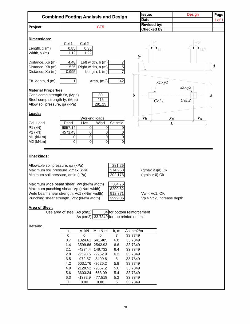
Page1 of 1
Dimensions:Col.1 Col.2
Length, x (m) 0.85 0.35 Ratio, b/aWidth, y (m) 1.12 1.22 Distance, Xa (m)
Distance, Xp (m) 4.48 Left width, b (m) 7Distance, Xb (m) 1.525 Right width, a (m) 5Distance, Xa (m) 0.995 Length, L (m) 7
Eff. depth, d (m) 1 Area, (m2) 42
Material Properties:Conc comp strength f'c, (Mpa) 30Steel comp strength fy, (Mpa) 415Allow soil pressure, qa (kPa) 281.25
Loads:
Col. Load Dead Live Wind SeismicP1 (kN) 6857.14 0 0 0P2 (kN) 4571.43 0 0 0M1 (kN.m) 0 0 0 0M2 (kN.m) 0 0 0 0
Checkings:
Allowable soil pressure, qa (kPa) 281.25Maximum soil pressure, qmax (kPa) 274.953 (qmax < qa) OkMinimum soil pressure, qmin (kPa) 202.173 (qmin > 0) Ok
Maximum wide beam shear, Vw (kN/m width) 364.76Maximum punching shear, Vp (kN/m width) 8200.62Wide beam shear strength, Vc1 (kN/m width) 912.871 Vw < Vc1, OKPunching shear strength, Vc2 (kN/m width) 3999.06 Vp > Vc2, increase depth
Area of Steel:Use area of steel, As (cm2) 34 for bottom reinforcement
As (cm2) 33.7349 for top reinforcement
Details:x V, kN M, kN-m b, m As, cm2/m0 0 0 7 33.7349
0.7 1824.61 641.485 6.8 33.73491.4 3599.86 2542.93 6.6 33.73492.1 -4274.4 149.732 6.4 33.73492.8 -2598.5 -2252.9 6.2 33.73493.5 -972.57 -3499.8 6 33.73494.2 603.176 -3626.2 5.8 33.73494.9 2128.52 -2667.2 5.6 33.73495.6 3603.24 -658.09 5.4 33.73496.3 -1372.9 477.518 5.2 33.73497 0.00 0.00 5 33.7349
Working loads
Project: CF5 Revised by:Checked by:
Combined Footing Analysis and Design Issue: DesignDate:
XaXpXbL
abCol.2Col.1
x1×y1x2×y2
fy
d
70

Page1 of 1
Dimensions:Col.1 Col.2
Length, x (m) 0.3 0.8 Ratio, b/aWidth, y (m) 0.8 0.8 Distance, Xa (m)
Distance, Xp (m) 4.555 Left width, b (m) 5Distance, Xb (m) 3.585 Right width, a (m) 8Distance, Xa (m) 2.36 Length, L (m) 10.5
Eff. depth, d (m) 1.2 Area, (m2) 68.25
Material Properties:Conc comp strength f'c, (Mpa) 30Steel comp strength fy, (Mpa) 415Allow soil pressure, qa (kPa) 281.25
Loads:
Col. Load Dead Live Wind SeismicP1 (kN) 4285.71 0 0 0P2 (kN) 7714.29 0 0 0M1 (kN.m) 0 0 0 0M2 (kN.m) 0 0 0 0
Checkings:
Allowable soil pressure, qa (kPa) 281.25Maximum soil pressure, qmax (kPa) 256.964 (qmax < qa) OkMinimum soil pressure, qmin (kPa) 60.8704 (qmin > 0) Ok
Maximum wide beam shear, Vw (kN/m width) 295.907Maximum punching shear, Vp (kN/m width) 9963.89Wide beam shear strength, Vc1 (kN/m width) 1095.45 Vw < Vc1, OKPunching shear strength, Vc2 (kN/m width) 3999.06 Vp > Vc2, increase depth
Area of Steel:Use area of steel, As (cm2) 34 for bottom reinforcement
As (cm2) 40.4819 for top reinforcement
Details:x V, kN M, kN-m b, m As, cm2/m0 0 0 5 40.4819
1.05 681.618 342.733 5.3 40.48192.1 1543.75 1494.58 5.6 40.48193.15 2601.9 3653.22 5.9 40.48194.2 -2128.4 3342.61 6.2 40.48195.25 -631.71 1872.99 6.5 40.48196.3 1107.53 2100.9 6.8 40.48197.35 3104.82 4289.12 7.1 40.48198.4 -5424.3 5908.75 7.4 40.48199.45 -2864.5 1531.17 7.7 40.48199.5 0.00 0.00 6.2 33.7349
Checked by:
Combined Footing Analysis and Design Issue: DesignDate:
Working loads
Project: CF6 Revised by:
XaXpXbL
abCol.2Col.1
x1×y1x2×y2
fy
d
71

Page1 of 1
Dimensions:Col.1 Col.2
Length, x (m) 0.3 0.8 Ratio, b/aWidth, y (m) 0.8 0.8 Distance, Xa (m)
Distance, Xp (m) 4.55 Left width, b (m) 4Distance, Xb (m) 1.5 Right width, a (m) 6Distance, Xa (m) 2.5 Length, L (m) 8.55
Eff. depth, d (m) 1.1 Area, (m2) 42.75
Material Properties:Conc comp strength f'c, (Mpa) 30Steel comp strength fy, (Mpa) 415Allow soil pressure, qa (kPa) 281.25
Loads:
Col. Load Dead Live Wind SeismicP1 (kN) 2142.86 0 0 0P2 (kN) 7042.86 0 0 0M1 (kN.m) 0 0 0 0M2 (kN.m) 0 0 0 0
Checkings:
Allowable soil pressure, qa (kPa) 281.25Maximum soil pressure, qmax (kPa) 276 (qmax < qa) OkMinimum soil pressure, qmin (kPa) 108.756 (qmin > 0) Ok
Maximum wide beam shear, Vw (kN/m width) 440.731Maximum punching shear, Vp (kN/m width) 8842Wide beam shear strength, Vc1 (kN/m width) 1004.16 Vw < Vc1, OKPunching shear strength, Vc2 (kN/m width) 3999.06 Vp > Vc2, increase depth
Area of Steel:Use area of steel, As (cm2) 37.5 for bottom reinforcement
As (cm2) 37.1084 for top reinforcement
Details:x V, kN M, kN-m b, m As, cm2/m0 0 0 4 37.1084
0.855 744.063 310.921 4.2 37.10841.71 -1408.2 671.903 4.4 37.1084
2.565 -450.42 -130.7 4.6 37.10843.42 623.572 -65.189 4.8 37.1084
4.275 1820.09 970.521 5 37.10845.13 3145.4 3083.87 5.2 37.1084
5.985 4605.77 6387.65 5.4 37.10846.84 -3652.5 3210.62 5.6 37.1084
7.695 -1903.2 824.806 5.8 37.10848.55 0.00 0.00 6 37.1084
Checked by:
Combined Footing Analysis and Design Issue: DesignDate:
Working loads
Project: CF7 Revised by:
XaXpXbL
abCol.2Col.1
x1×y1x2×y2
fy
d
72
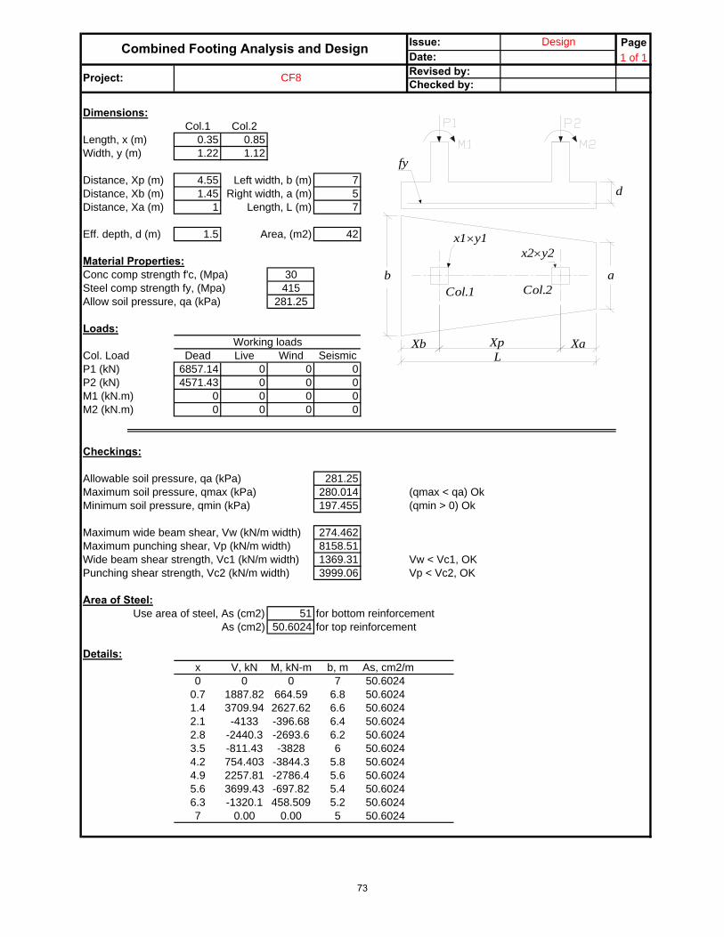
Page1 of 1
Dimensions:Col.1 Col.2
Length, x (m) 0.35 0.85 Ratio, b/aWidth, y (m) 1.22 1.12 Distance, Xa (m)
Distance, Xp (m) 4.55 Left width, b (m) 7Distance, Xb (m) 1.45 Right width, a (m) 5Distance, Xa (m) 1 Length, L (m) 7
Eff. depth, d (m) 1.5 Area, (m2) 42
Material Properties:Conc comp strength f'c, (Mpa) 30Steel comp strength fy, (Mpa) 415Allow soil pressure, qa (kPa) 281.25
Loads:
Col. Load Dead Live Wind SeismicP1 (kN) 6857.14 0 0 0P2 (kN) 4571.43 0 0 0M1 (kN.m) 0 0 0 0M2 (kN.m) 0 0 0 0
Checkings:
Allowable soil pressure, qa (kPa) 281.25Maximum soil pressure, qmax (kPa) 280.014 (qmax < qa) OkMinimum soil pressure, qmin (kPa) 197.455 (qmin > 0) Ok
Maximum wide beam shear, Vw (kN/m width) 274.462Maximum punching shear, Vp (kN/m width) 8158.51Wide beam shear strength, Vc1 (kN/m width) 1369.31 Vw < Vc1, OKPunching shear strength, Vc2 (kN/m width) 3999.06 Vp < Vc2, OK
Area of Steel:Use area of steel, As (cm2) 51 for bottom reinforcement
As (cm2) 50.6024 for top reinforcement
Details:x V, kN M, kN-m b, m As, cm2/m0 0 0 7 50.6024
0.7 1887.82 664.59 6.8 50.60241.4 3709.94 2627.62 6.6 50.60242.1 -4133 -396.68 6.4 50.60242.8 -2440.3 -2693.6 6.2 50.60243.5 -811.43 -3828 6 50.60244.2 754.403 -3844.3 5.8 50.60244.9 2257.81 -2786.4 5.6 50.60245.6 3699.43 -697.82 5.4 50.60246.3 -1320.1 458.509 5.2 50.60247 0.00 0.00 5 50.6024
Checked by:
Combined Footing Analysis and Design Issue: DesignDate:
Working loads
Project: CF8 Revised by:
XaXpXbL
abCol.2Col.1
x1×y1x2×y2
fy
d
73

Page1 of 1
Dimensions:Col.1 Col.2
Length, x (m) 0.8 0.8 Ratio, b/aWidth, y (m) 0.8 0.8 Distance, Xa (m)
Distance, Xp (m) 5.8 Left width, b (m) 6.5Distance, Xb (m) 1 Right width, a (m) 6.5Distance, Xa (m) 1 Length, L (m) 7.8
Eff. depth, d (m) 1.2 Area, (m2) 50.7
Material Properties:Conc comp strength f'c, (Mpa) 30Steel comp strength fy, (Mpa) 415Allow soil pressure, qa (kPa) 281.25
Loads:
Col. Load Dead Live Wind SeismicP1 (kN) 7042.86 0 0 0P2 (kN) 7042.86 0 0 0M1 (kN.m) 0 0 0 0M2 (kN.m) 0 0 0 0
Checkings:
Allowable soil pressure, qa (kPa) 281.25Maximum soil pressure, qmax (kPa) 277.825 (qmax < qa) OkMinimum soil pressure, qmin (kPa) 208.369 (qmin > 0) Ok
Maximum wide beam shear, Vw (kN/m width) 505.641Maximum punching shear, Vp (kN/m width) 8304.18Wide beam shear strength, Vc1 (kN/m width) 1095.45 Vw < Vc1, OKPunching shear strength, Vc2 (kN/m width) 3999.06 Vp < Vc2, OK
Area of Steel:Use area of steel, As (cm2) 40.5 for bottom reinforcement
As (cm2) 40.4819 for top reinforcement
Details:x V, kN M, kN-m b, m As, cm2/m0 0 0 6.5 40.4819
0.78 1972 769.08 6.5 40.48191.56 -5916 -2445.3 6.5 40.48192.34 -3944 -6290.7 6.5 40.48193.12 -1972 -8597.9 6.5 40.48193.9 0 -9367 6.5 40.48194.68 1972 -8597.9 6.5 40.48195.46 3944 -6290.7 6.5 40.48196.24 5916 -2445.3 6.5 40.48197.02 -1972 769.078 6.5 40.48199.8 0.00 0.00 6.6 26.988
Checked by:
Combined Footing Analysis and Design Issue: DesignDate:
Working loads
Project: CF9 Revised by:
XaXpXbL
abCol.2Col.1
x1×y1x2×y2
fy
d
74

Page1 of 1
Dimensions:Col.1 Col.2
Length, x (m) 0.8 0.8 Ratio, b/aWidth, y (m) 0.8 0.8 Distance, Xa (m)
Distance, Xp (m) 4.555 Left width, b (m) 6.4Distance, Xb (m) 1.722 Right width, a (m) 6.4Distance, Xa (m) 1.722 Length, L (m) 8
Eff. depth, d (m) 1.15 Area, (m2) 51.2
Material Properties:Conc comp strength f'c, (Mpa) 30Steel comp strength fy, (Mpa) 415Allow soil pressure, qa (kPa) 281.25
Loads:
Col. Load Dead Live Wind SeismicP1 (kN) 7042.86 0 0 0P2 (kN) 7042.86 0 0 0M1 (kN.m) 0 0 0 0M2 (kN.m) 0 0 0 0
Checkings:
Allowable soil pressure, qa (kPa) 281.25Maximum soil pressure, qmax (kPa) 275.215 (qmax < qa) OkMinimum soil pressure, qmin (kPa) 206.256 (qmin > 0) Ok
Maximum wide beam shear, Vw (kN/m width) 280.288Maximum punching shear, Vp (kN/m width) 8357.77Wide beam shear strength, Vc1 (kN/m width) 1049.8 Vw < Vc1, OKPunching shear strength, Vc2 (kN/m width) 3999.06 Vp < Vc2, OK
Area of Steel:Use area of steel, As (cm2) 39 for bottom reinforcement
As (cm2) 38.7952 for top reinforcement
Details:x V, kN M, kN-m b, m As, cm2/m0 0 0 6.4 38.7952
0.8 1972.67 789.076 6.4 38.79521.6 3945.18 3156.23 6.4 38.79522.4 -3942.4 416.25 6.4 38.79523.2 -1970.2 -1948.8 6.4 38.79524 1.84961 -2736.1 6.4 38.7952
4.8 1973.78 -1945.9 6.4 38.79525.6 3945.55 421.859 6.4 38.79526.4 -3942.8 3154.17 6.4 38.79527.2 -1971.3 788.528 6.4 38.79529.8 0.00 0.01 6.6 26.988
Checked by:
Combined Footing Analysis and Design Issue: DesignDate:
Working loads
Project: CF10 Revised by:
XaXpXbL
abCol.2Col.1
x1×y1x2×y2
fy
d
75

DESIGN OF COLUMNS

Rectangular Short Column with Biaxial bending - Bresler method
COLUMN NO C1Load Case 1.5*(DL - EQX)Grade of Concrete M30Grade of Steel Fe415Characteristic compressive strength of concrete , fck ( N/mm2 ) 30Characteristic yield strength of steel , fy ( N/mm2 ) 415Unit weight of concrete , γc ( kN/m3 ) 25Partial safety factor for concrete 1.5Exposure condition MildNominal Cover to exposure condition( mm ) 40Assumed effective cover all around , d' ( mm ) 50
Dimesions of the Column
Unsupported length of column, L = 3600 mmLeast lateral dimension = 230 mmBreadth of the column B (mm) = 230Depth of the Column D (mm) = 230
Effective length of the column , lex , ( m ) = 2.34Effective length of the column , ley , ( m ) = 2.34
Check for Slenderness ratio, L/D
Slenderness ratio , λex = 10.17 <12 column is ShortSlenderness ratio , λey = 10.17 <12 column is Short
Design FactorsFactored load, Pu = 275 KN
1 Check for accidental eccentricityEquivalent eccentricity of loads is given by
Mux/pu = 90.91 mmMuy/pu = 327.27 mm
Both are more than 20mm minimum
2 Assume percentage of steel( assuming steel larger than required by P and Mx)
d'/D = 0.2
Mx = 0.07fck x b x D2
Pu = 0.17fck x b x D
25 KN-m
= 3 KN-m
Factored moment acting parallelto the larger dimension , Mux
Factored moment acting parallelto the shorter dimension, Muy
=
76
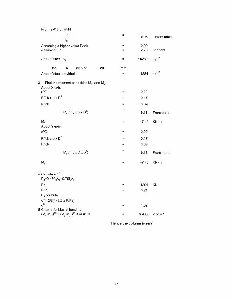
From SP16 chart44P =fck
Assuming a higher value P/fck = 0.09Assumed , P = 2.70 per cent
Area of steel, As = 1428.30 mm2
Use 6 no.s of 20 mm= 1884 mm2
3About X-axis
= 0.22
= 0.17
P/fck = 0.09
From table
Mx1 = 47.45 KN-mAbout Y-axis
= 0.22
= 0.17P/fck = 0.09
From table
My1 = 47.45 KN-m
4 Calculate αn
Pz=0.45fckAc+0.75fyAs
Pz = 1301 KNP/Pz = 0.21By formulaαn= 2/3[1+5/2 x P/Pz]αn = 1.02
5 Criteria for biaxial bending(Mx/Mx1)
αn + (My/My1)αn < or =1.0 = 0.9000 < or = 1
Hence the column is safe
From table
0.13
0.13
Area of steel provided
=
=
d'/D
P/fck x b x D2
P/fck x b x D2
Mx1/(fck x b x D2)
My1/(fck x D x b2)
Find the moment capacities Mx1 and My1
d'/D
0.06
77

Rectangular Short Column with Biaxial bending - Bresler method
COLUMN NO C1aLoad Case 1.5*(DL - EQX)Grade of Concrete M30Grade of Steel Fe415Characteristic compressive strength of concrete , fck ( N/mm2 ) 30Characteristic yield strength of steel , fy ( N/mm2 ) 415Unit weight of concrete , γc ( kN/m3 ) 25Partial safety factor for concrete 1.5Exposure condition MildNominal Cover to exposure condition( mm ) 40Assumed effective cover all around , d' ( mm ) 50
Dimesions of the Column
Unsupported length of column, L = 3600 mmLeast lateral dimension = 400 mmBreadth of the column B (mm) = 400Depth of the Column D (mm) = 700
Effective length of the column , lex , ( m ) = 2.34Effective length of the column , ley , ( m ) = 2.34
Check for Slenderness ratio, L/D
Slenderness ratio , λex = 5.85 <12 column is ShortSlenderness ratio , λey = 3.34 <12 column is Short
Design Factors
Factored load, Pu = 1307.33 KN
1 Check for accidental eccentricityEquivalent eccentricity of loads is given by
Mux/pu = 260.10 mmMuy/pu = 68.84 mm
Both are more than 20mm minimum
2 Assume percentage of steel( assuming steel larger than required by P and Mx)
d'/D = 0.1
Mx = 0.06fck x b x D2
340.03 KN-m
= 769.88 KN-m
Factored moment acting parallelto the larger dimension , Mux
Factored moment acting parallelto the shorter dimension, Muy
=
78

Pu = 0.16fck x b x D
From SP16 chart44P =fck
Assuming a higher value P/fck = 0.075Assumed , P = 2.25 per cent
Area of steel, As = 6300.00 mm2
Use 16 no.s of 25 mm= 7850 mm2
3
About X-axis= 0.07
= 0.16
P/fck = 0.075
From table
Mx1 = 705.60 KN-m
About Y-axis = 0.13
= 0.16P/fck = 0.075
From table
My1 = 403.20 KN-m
4 Calculate αn
Pz=0.45fckAc+0.75fyAs
Pz = 6223 KNP/Pz = 0.21
By formulaαn= 2/3[1+5/2 x P/Pz]αn = 1.02
5 Criteria for biaxial bending(Mx/Mx1)
αn + (My/My1)αn < or =1.0 = 0.6903 < or = 1
Hence the column is safe
From table
0.12
0.12
Area of steel provided
=
=
d'/D
P/fck x b x D2
P/fck x b x D2
Mx1/(fck x b x D2)
My1/(fck x D x b2)
Find the moment capacities Mx1 and My1
d'/D
0.05
79

Rectangular Short Column with Biaxial bending - Bresler method
COLUMN NO C2Load Case 1.5*(DL - EQX)Grade of Concrete M30Grade of Steel Fe415Characteristic compressive strength of concrete , fck ( N/mm2 ) 30Characteristic yield strength of steel , fy ( N/mm2 ) 415Unit weight of concrete , γc ( kN/m3 ) 25Partial safety factor for concrete 1.5Exposure condition MildNominal Cover to exposure condition( mm ) 40Assumed effective cover all around , d' ( mm ) 50
Dimesions of the Column
Unsupported length of column, L = 3750 mmLeast lateral dimension = 350 mmBreadth of the column B (mm) = 350Depth of the Column D (mm) = 800
Effective length of the column , lex , ( m ) = 2.34Effective length of the column , ley , ( m ) = 2.34
Check for Slenderness ratio, L/D
Slenderness ratio , λex = 7.80 <12 column is ShortSlenderness ratio , λey = 2.93 <12 column is Short
Design Factors
Factored load, Pu = 925 KN
1 Check for accidental eccentricityEquivalent eccentricity of loads is given by
Mux/pu = 362.01 mmMuy/pu = 100.56 mm
Both are more than 20mm minimum
2 Assume percentage of steel( assuming steel larger than required by P and Mx)
d'/D = 0.1
Mx = 0.06fck x b x D2
Factored moment acting parallelto the larger dimension , Mux
Factored moment acting parallelto the shorter dimension, Muy
= 334 KN-m
= 228.13 KN-m
80

Pu = 0.12fck x b x D
From SP16 chart44P =fck
Assuming a higher value P/fck = 0.075Assumed , P = 2.25 per cent
Area of steel, As = 5400.00 mm2
Use 12 no.s of 25 mm= 5888 mm2
3
About X-axis= 0.06
= 0.12
P/fck = 0.075
From table
Mx1 = 691.20 KN-m
About Y-axis = 0.17
= 0.12P/fck = 0.075
From table
My1 = 269.20 KN-m
4 Calculate αn
Pz=0.45fckAc+0.75fyAs
Pz = 5072 KNP/Pz = 0.18
By formulaαn= 2/3[1+5/2 x P/Pz]αn = 0.97
5 Criteria for biaxial bending(Mx/Mx1)
αn + (My/My1)αn < or =1.0 = 0.8613 < or = 1
Hence the column is safe
Find the moment capacities Mx1 and My1
d'/D
0.05
0.12
0.12
Area of steel provided
=
=
d'/D
P/fck x b x D2
P/fck x b x D2
Mx1/(fck x b x D2)
My1/(fck x D x b2)
From table
81

Rectangular Short Column with Biaxial bending - Bresler method
COLUMN NO C3Load Case 1.2*(DL + LL - EQX)Grade of Concrete M30Grade of Steel Fe415Characteristic compressive strength of concrete , fck ( N/mm2 ) 30Characteristic yield strength of steel , fy ( N/mm2 ) 415Unit weight of concrete , γc ( kN/m3 ) 25Partial safety factor for concrete 1.5Exposure condition MildNominal Cover to exposure condition( mm ) 40Assumed effective cover all around , d' ( mm ) 60
Dimesions of the Column
Unsupported length of column, L = 3600 mmLeast lateral dimension = 300 mmBreadth of the column B (mm) = 300Depth of the Column D (mm) = 600
Effective length of the column , lex , ( m ) = 2.34Effective length of the column , ley , ( m ) = 2.34
Check for Slenderness ratio, L/D
Slenderness ratio , λex = 7.80 <12 column is ShortSlenderness ratio , λey = 3.90 <12 column is Short
Design Factors
Factored load, Pu = 366.32 KN
1 Check for accidental eccentricityEquivalent eccentricity of loads is given by
Mux/pu = 443.03 mmMuy/pu = 245.69 mm
Both are more than 20mm minimum
2 Assume percentage of steel( assuming steel larger than required by P and Mx)
d'/D = 0.1
Mx = 0.05fck x b x D2
Factored moment acting parallelto the larger dimension , Mux
Factored moment acting parallelto the shorter dimension, Muy
= 162.29 KN-m
= 353.51 KN-m
82

Pu = 0.07fck x b x D
From SP16 chart44P =fck
Assuming a higher value P/fck = 0.105Assumed , P = 3.15 per cent
Area of steel, As = 5670.00 mm2
Use 12 no.s of 25 mm= 5888 mm2
3
About X-axis= 0.10
= 0.07
P/fck = 0.105
From table
Mx1 = 405.00 KN-m
About Y-axis = 0.20
= 0.07P/fck = 0.105
From table
My1 = 202.50 KN-m
4 Calculate αn
Pz=0.45fckAc+0.75fyAs
Pz = 4262 KNP/Pz = 0.09
By formulaαn= 2/3[1+5/2 x P/Pz]αn = 0.81
5 Criteria for biaxial bending(Mx/Mx1)
αn + (My/My1)αn < or =1.0 = 0.9919 < or = 1
Hence the column is safe
Find the moment capacities Mx1 and My1
d'/D
0.07
0.125
0.125
Area of steel provided
=
=
d'/D
P/fck x b x D2
P/fck x b x D2
Mx1/(fck x b x D2)
My1/(fck x D x b2)
From table
83
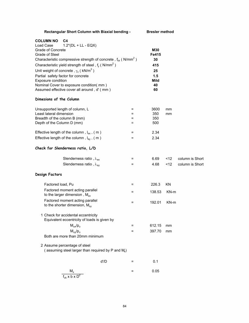
Rectangular Short Column with Biaxial bending - Bresler method
COLUMN NO C4Load Case 1.2*(DL + LL - EQX)Grade of Concrete M30Grade of Steel Fe415Characteristic compressive strength of concrete , fck ( N/mm2 ) 30Characteristic yield strength of steel , fy ( N/mm2 ) 415Unit weight of concrete , γc ( kN/m3 ) 25Partial safety factor for concrete 1.5Exposure condition MildNominal Cover to exposure condition( mm ) 40Assumed effective cover all around , d' ( mm ) 60
Dimesions of the Column
Unsupported length of column, L = 3600 mmLeast lateral dimension = 350 mmBreadth of the column B (mm) = 350Depth of the Column D (mm) = 500
Effective length of the column , lex , ( m ) = 2.34Effective length of the column , ley , ( m ) = 2.34
Check for Slenderness ratio, L/D
Slenderness ratio , λex = 6.69 <12 column is ShortSlenderness ratio , λey = 4.68 <12 column is Short
Design Factors
Factored load, Pu = 226.3 KN
1 Check for accidental eccentricityEquivalent eccentricity of loads is given by
Mux/pu = 612.15 mmMuy/pu = 397.70 mm
Both are more than 20mm minimum
2 Assume percentage of steel( assuming steel larger than required by P and Mx)
d'/D = 0.1
Mx = 0.05fck x b x D2
138.53 KN-m
= 192.01 KN-m
Factored moment acting parallelto the larger dimension , Mux
Factored moment acting parallelto the shorter dimension, Muy
=
84

Pu = 0.04fck x b x D
From SP16 chart44P =fck
Assuming a higher value P/fck = 0.105Assumed , P = 3.15 per cent
Area of steel, As = 5512.50 mm2
Use 12 no.s of 25 mm= 5888 mm2
3
About X-axis= 0.12
= 0.04
P/fck = 0.06
From table
Mx1 = 341.25 KN-m
About Y-axis = 0.17
= 0.04P/fck = 0.105
From table
My1 = 238.88 KN-m
4 Calculate αn
Pz=0.45fckAc+0.75fyAs
Pz = 4195 KNP/Pz = 0.05
By formulaαn= 2/3[1+5/2 x P/Pz]αn = 0.76
5 Criteria for biaxial bending(Mx/Mx1)
αn + (My/My1)αn < or =1.0 = 0.9799 < or = 1
Hence the column is safe
From table
0.13
0.13
Area of steel provided
=
=
d'/D
P/fck x b x D2
P/fck x b x D2
Mx1/(fck x b x D2)
My1/(fck x D x b2)
Find the moment capacities Mx1 and My1
d'/D
0.07
85

Rectangular Short Column with Biaxial bending - Bresler method
COLUMN NO C5Load Case 1.5*(DL - EQX)Grade of Concrete M30Grade of Steel Fe415Characteristic compressive strength of concrete , fck ( N/mm2 ) 30Characteristic yield strength of steel , fy ( N/mm2 ) 415Unit weight of concrete , γc ( kN/m3 ) 25Partial safety factor for concrete 1.5Exposure condition MildNominal Cover to exposure condition( mm ) 40Assumed effective cover all around , d' ( mm ) 50
Dimesions of the Column
Unsupported length of column, L = 3600 mmLeast lateral dimension = 350 mmBreadth of the column B (mm) = 350Depth of the Column D (mm) = 600
Effective length of the column , lex , ( m ) = 2.34Effective length of the column , ley , ( m ) = 2.34
Check for Slenderness ratio, L/D
Slenderness ratio , λex = 6.69 <12 column is ShortSlenderness ratio , λey = 3.90 <12 column is Short
Design Factors
Factored load, Pu = 830.8 KN
1 Check for accidental eccentricityEquivalent eccentricity of loads is given by
Mux/pu = 71.77 mmMuy/pu = 108.33 mm
Both are more than 20mm minimum
2 Assume percentage of steel( assuming steel larger than required by P and Mx)
d'/D = 0.1
Mx = 0.02fck x b x D2
59.63 KN-m
= 224.86 KN-m
Factored moment acting parallelto the larger dimension , Mux
Factored moment acting parallelto the shorter dimension, Muy
=
86

Pu = 0.13fck x b x D
From SP16 chart44P =fck
Assuming a higher value P/fck = 0.075Assumed , P = 2.25 per cent
Area of steel, As = 4725.00 mm2
Use 10 no.s of 25 mm= 4906 mm2
3
About X-axis= 0.08
= 0.13
P/fck = 0.075
From table
Mx1 = 453.60 KN-m
About Y-axis = 0.14
= 0.13P/fck = 0.075
From table
My1 = 264.60 KN-m
4 Calculate αn
Pz=0.45fckAc+0.75fyAs
Pz = 4362 KNP/Pz = 0.19
By formulaαn= 2/3[1+5/2 x P/Pz]αn = 0.99
5 Criteria for biaxial bending(Mx/Mx1)
αn + (My/My1)αn < or =1.0 = 0.4786 < or = 1
Hence the column is safe
From table
0.12
0.12
Area of steel provided
=
=
d'/D
P/fck x b x D2
P/fck x b x D2
Mx1/(fck x b x D2)
My1/(fck x D x b2)
Find the moment capacities Mx1 and My1
d'/D
0.05
87

Rectangular Short Column with Biaxial bending - Bresler method
COLUMN NO C6Load Case 1.5*(DL - EQX)Grade of Concrete M30Grade of Steel Fe415Characteristic compressive strength of concrete , fck ( N/mm2 ) 30Characteristic yield strength of steel , fy ( N/mm2 ) 415Unit weight of concrete , γc ( kN/m3 ) 25Partial safety factor for concrete 1.5Exposure condition MildNominal Cover to exposure condition( mm ) 40Assumed effective cover all around , d' ( mm ) 50
Dimesions of the Column
Unsupported length of column, L = 3600 mmLeast lateral dimension = 400 mmBreadth of the column B (mm) = 400Depth of the Column D (mm) = 900
Effective length of the column , lex , ( m ) = 2.34Effective length of the column , ley , ( m ) = 2.34
Check for Slenderness ratio, L/D
Slenderness ratio , λex = 5.85 <12 column is ShortSlenderness ratio , λey = 2.60 <12 column is Short
Design Factors
Factored load, Pu = 560.34 KN
1 Check for accidental eccentricityEquivalent eccentricity of loads is given by
Mux/pu = 1005.34 mmMuy/pu = 160.62 mm
Both are more than 20mm minimum
2 Assume percentage of steel( assuming steel larger than required by P and Mx)
d'/D = 0.1
Mx = 0.06fck x b x D2
563.33 KN-m
= 210.34 KN-m
Factored moment acting parallelto the larger dimension , Mux
Factored moment acting parallelto the shorter dimension, Muy
=
88

Pu = 0.05fck x b x D
From SP16 chart44P =fck
Assuming a higher value P/fck = 0.0675Assumed , P = 2.03 per cent
Area of steel, As = 7290.00 mm2
Use 16 no.s of 25 mm= 7850 mm2
3
About X-axis= 0.06
= 0.05
P/fck = 0.0675
From table
Mx1 = 1166.40 KN-m
About Y-axis = 0.13
= 0.05P/fck = 0.0675
From table
My1 = 518.40 KN-m
4 Calculate αn
Pz=0.45fckAc+0.75fyAs
Pz = 7303 KNP/Pz = 0.08
By formulaαn= 2/3[1+5/2 x P/Pz]αn = 0.80
5 Criteria for biaxial bending(Mx/Mx1)
αn + (My/My1)αn < or =1.0 = 0.8063 < or = 1
Hence the column is safe
From table
0.12
0.12
Area of steel provided
=
=
d'/D
P/fck x b x D2
P/fck x b x D2
Mx1/(fck x b x D2)
My1/(fck x D x b2)
Find the moment capacities Mx1 and My1
d'/D
0.045
89

Rectangular Short Column with Biaxial bending - Bresler method
COLUMN NO C7Load Case 1.5*(DL - EQX)Grade of Concrete M30Grade of Steel Fe415Characteristic compressive strength of concrete , fck ( N/mm2 ) 30Characteristic yield strength of steel , fy ( N/mm2 ) 415Unit weight of concrete , γc ( kN/m3 ) 25Partial safety factor for concrete 1.5Exposure condition MildNominal Cover to exposure condition( mm ) 40Assumed effective cover all around , d' ( mm ) 60
Dimesions of the Column
Unsupported length of column, L = 3600 mmLeast lateral dimension = 800 mmBreadth of the column B (mm) = 800Depth of the Column D (mm) = 800
Effective length of the column , lex , ( m ) = 2.34Effective length of the column , ley , ( m ) = 2.34
Check for Slenderness ratio, L/D
Slenderness ratio , λex = 2.93 <12 column is ShortSlenderness ratio , λey = 2.93 <12 column is Short
Design Factors
Factored load, Pu = 4861.81 KN
1 Check for accidental eccentricityEquivalent eccentricity of loads is given by
Mux/pu = 373.87 mmMuy/pu = 18.51 mm
Both are more than 20mm minimum
2 Assume percentage of steel( assuming steel larger than required by P and Mx)
d'/D = 0.1
Mx = 0.12fck x b x D2
Factored moment acting parallelto the larger dimension , Mux
Factored moment acting parallelto the shorter dimension, Muy
= 1817.69 KN-m
= 0.23 KN-m
90

Pu = 0.25fck x b x D
From SP16 chart44P =fck
Assuming a higher value P/fck = 0.0825Assumed , P = 2.48 per cent
Area of steel, As = 15840.00 mm2
Use 20 no.s of 32 mm= 16077 mm2
3
About X-axis= 0.08
= 0.25
P/fck = 0.0825
From table
Mx1 = 1996.80 KN-m
About Y-axis = 0.08
= 0.25P/fck = 0.0825
From table
My1 = 1996.80 KN-m
4 Calculate αn
Pz=0.45fckAc+0.75fyAs
Pz = 13644 KNP/Pz = 0.36
By formulaαn= 2/3[1+5/2 x P/Pz]αn = 1.27
5 Criteria for biaxial bending(Mx/Mx1)
αn + (My/My1)αn < or =1.0 = 0.9075 < or = 1
Hence the column is safe
Find the moment capacities Mx1 and My1
d'/D
0.055
0.13
0.13
Area of steel provided
=
=
d'/D
P/fck x b x D2
P/fck x b x D2
Mx1/(fck x b x D2)
My1/(fck x D x b2)
From table
91

Rectangular Short Column with Biaxial bending - Bresler method
COLUMN NO C8Load Case 1.5*(DL - EQX)Grade of Concrete M30Grade of Steel Fe415Characteristic compressive strength of concrete , fck ( N/mm2 ) 30Characteristic yield strength of steel , fy ( N/mm2 ) 415Unit weight of concrete , γc ( kN/m3 ) 25Partial safety factor for concrete 1.5Exposure condition MildNominal Cover to exposure condition( mm ) 40Assumed effective cover all around , d' ( mm ) 50
Dimesions of the Column
Unsupported length of column, L = 3600 mmLeast lateral dimension = 300 mmBreadth of the column B (mm) = 300Depth of the Column D (mm) = 800
Effective length of the column , lex , ( m ) = 2.34Effective length of the column , ley , ( m ) = 2.34
Check for Slenderness ratio, L/D
Slenderness ratio , λex = 7.80 <12 column is ShortSlenderness ratio , λey = 2.93 <12 column is Short
Design Factors
Factored load, Pu = 895 KN
1 Check for accidental eccentricityEquivalent eccentricity of loads is given by
Mux/pu = 362.01 mmMuy/pu = 100.56 mm
Both are more than 20mm minimum
2 Assume percentage of steel( assuming steel larger than required by P and Mx)
d'/D = 0.1
Mx = 0.06fck x b x D2
Factored moment acting parallelto the larger dimension , Mux
Factored moment acting parallelto the shorter dimension, Muy
= 324 KN-m
= 240.15 KN-m
92

Pu = 0.12fck x b x D
From SP16 chart44P =fck
Assuming a higher value P/fck = 0.075Assumed , P = 2.25 per cent
Area of steel, As = 5400.00 mm2
Use 12 no.s of 25 mm= 5888 mm2
3
About X-axis= 0.06
= 0.12
P/fck = 0.075
From table
Mx1 = 691.20 KN-m
About Y-axis = 0.17
= 0.12P/fck = 0.075
From table
My1 = 259.20 KN-m
4 Calculate αn
Pz=0.45fckAc+0.75fyAs
Pz = 5072 KNP/Pz = 0.18
By formulaαn= 2/3[1+5/2 x P/Pz]αn = 0.97
5 Criteria for biaxial bending(Mx/Mx1)
αn + (My/My1)αn < or =1.0 = 0.8413 < or = 1
Hence the column is safe
Find the moment capacities Mx1 and My1
d'/D
0.05
0.12
0.12
Area of steel provided
=
=
d'/D
P/fck x b x D2
P/fck x b x D2
Mx1/(fck x b x D2)
My1/(fck x D x b2)
From table
93

Rectangular Short Column with Biaxial bending - Bresler method
COLUMN NO C9Load Case 1.5*(DL - EQX)Grade of Concrete M30Grade of Steel Fe415Characteristic compressive strength of concrete , fck ( N/mm2 ) 30Characteristic yield strength of steel , fy ( N/mm2 ) 415Unit weight of concrete , γc ( kN/m3 ) 25Partial safety factor for concrete 1.5Exposure condition MildNominal Cover to exposure condition( mm ) 40Assumed effective cover all around , d' ( mm ) 50
Dimesions of the Column
Unsupported length of column, L = 3600 mmLeast lateral dimension = 300 mmBreadth of the column B (mm) = 300Depth of the Column D (mm) = 400
Effective length of the column , lex , ( m ) = 2.34Effective length of the column , ley , ( m ) = 2.34
Check for Slenderness ratio, L/D
Slenderness ratio , λex = 7.80 <12 column is ShortSlenderness ratio , λey = 5.85 <12 column is Short
Design Factors
Factored load, Pu = 717.13 KN
1 Check for accidental eccentricityEquivalent eccentricity of loads is given by
Mux/pu = 157.18 mmMuy/pu = 125.50 mm
Both are more than 20mm minimum
2 Assume percentage of steel( assuming steel larger than required by P and Mx)
d'/D = 0.1
Mx = 0.08fck x b x D2
112.72 KN-m
= 60.37 KN-m
Factored moment acting parallelto the larger dimension , Mux
Factored moment acting parallelto the shorter dimension, Muy
=
94

Pu = 0.20fck x b x D
From SP16 chart44P =fck
Assuming a higher value P/fck = 0.105Assumed , P = 3.15 per cent
Area of steel, As = 3780.00 mm2
Use 8 no.s of 25 mm= 3925 mm2
3About X-axis
= 0.13
= 0.20
P/fck = 0.105
From table
Mx1 = 100.80 KN-mAbout Y-axis
= 0.17
= 0.20P/fck = 0.105
From tableMy1 = 75.60 KN-m
4 Calculate αn
Pz=0.45fckAc+0.75fyAs
Pz = 2842 KNP/Pz = 0.25
By formulaαn= 2/3[1+5/2 x P/Pz]αn = 1.09
5 Criteria for biaxial bending(Mx/Mx1)
αn + (My/My1)αn < or =1.0 = 0.9000 < or = 1
Hence the column is safe
From table
0.07
0.07
Area of steel provided
=
=
d'/D
P/fck x b x D2
P/fck x b x D2
Mx1/(fck x b x D2)
My1/(fck x D x b2)
Find the moment capacities Mx1 and My1
d'/D
0.07
95

Rectangular Short Column with Biaxial bending - Bresler method
COLUMN NO C10Load Case 1.5*(DL - EQX)Grade of Concrete M30Grade of Steel Fe415Characteristic compressive strength of concrete , fck ( N/mm2 ) 30Characteristic yield strength of steel , fy ( N/mm2 ) 415Unit weight of concrete , γc ( kN/m3 ) 25Partial safety factor for concrete 1.5Exposure condition MildNominal Cover to exposure condition( mm ) 40Assumed effective cover all around , d' ( mm ) 50
Dimesions of the Column
Unsupported length of column, L = 3600 mmLeast lateral dimension = 550 mmBreadth of the column B (mm) = 550Depth of the Column D (mm) = 850
Effective length of the column , lex , ( m ) = 2.34Effective length of the column , ley , ( m ) = 2.34
Check for Slenderness ratio, L/D
Slenderness ratio , λex = 4.25 <12 column is ShortSlenderness ratio , λey = 2.75 <12 column is Short
Design Factors
Factored load, Pu = 3015.88 KN
1 Check for accidental eccentricityEquivalent eccentricity of loads is given by
Mux/pu = 304.53 mmMuy/pu = 29.84 mm
Both are more than 20mm minimum
2 Assume percentage of steel( assuming steel larger than required by P and Mx)
d'/D = 0.1
Mx = 0.08fck x b x D2
Factored moment acting parallelto the larger dimension , Mux
Factored moment acting parallelto the shorter dimension, Muy
= 918.44 KN-m
= 2 KN-m
96

Pu = 0.22fck x b x D
From SP16 chart44P =fck
Assuming a higher value P/fck = 0.075Assumed , P = 2.25 per cent
Area of steel, As = 10518.75 mm2
Use 22 no.s of 25 mm= 10794 mm2
3
About X-axis= 0.06
= 0.22
P/fck = 0.075
From table
Mx1 = 1490.16 KN-m
About Y-axis = 0.09
= 0.22P/fck = 0.075
From table
My1 = 964.22 KN-m
4 Calculate αn
Pz=0.45fckAc+0.75fyAs
Pz = 9671 KNP/Pz = 0.31
By formulaαn= 2/3[1+5/2 x P/Pz]αn = 1.19
5 Criteria for biaxial bending(Mx/Mx1)
αn + (My/My1)αn < or =1.0 = 0.6207 < or = 1
Hence the column is safe
Find the moment capacities Mx1 and My1
d'/D
0.05
0.125
0.125
Area of steel provided
=
=
d'/D
P/fck x b x D2
P/fck x b x D2
Mx1/(fck x b x D2)
My1/(fck x D x b2)
From table
97

DESIGN OF BEAMS

Beam PB1 Support
Design Parameters
Load Case 14 [1.5*(DL - EQX)]Grade of Concrete M30Grade of Steel Fe415Characteristic compressive strength of concrete , fck ( N/mm2 ) 30Characteristic yield strength of steel , fy ( N/mm2 ) 415Unit weight of concrete , γc ( kN/m3 ) 24Partial safety factor for concrete 1.5Exposure condition MildNominal Cover to exposure condition( mm ) 20
Dimensions of the beam
C/C Span of the beam , l , ( m ) 10.80Breadth of the beam , b ( mm ) 250Overall depth of the beam , D ( mm ) 600
Details of reinforcements
Diameter of tension reinforcement ( mm ) 25 Diameter of compression reinforcement ( mm ) 25Diameter of stirrups ( mm ) 8
Effective depth
Effective depth , d ( mm ) ( 600-20-8-25/2 ) = 560
Design Moment, Shear Force
The moments and shears given below are taken from the STAAD.Pro 2004 output file.The partial factors of safety are already incorporated into the analysis.
Torsional Moment 0 kN-mBending Moment Mu(kN-m) 380Equivalent Bending Moment , Me ( kNm ) 380Shear force at critical distance , Vud ( kN ) 152Equivalent Shear (kN) 152
Singly reinforced or doubly reinforced section ?
The limiting moment of resistance , Mu,lim is given by
The limiting percentage of steel , pt,lim is given by
SectiontheofdepthEffectivedAxisNeutralofdepthLimitingxu
SectiontheofBreadthbWhere
0.416xu*d
bxu*0.362fckMulim
max
maxmax
==
=
=
98

The area of steel for a singly reinforced section with width , b and depth , d and ultimate moment , Mu is given by :
For ( M30 and Fe415 )
xu,max / d = 0.48
⇒ Mu,lim = ( 0.1389 x 30 x 250 x 559.5^2 / 1000000 ) = 326.11 kNm
⇒ pt,lim = ( 41.3 x 30 / 415 x 0.48 ) = 1.433
If Mu > Mu,lim , the section has to be i) get increased by depth or width ( preferably depth )ii) doubly reinforced
If Mu < Mu,lim , the section can be designed as singly reinforced.
Check for the type of section
Mu = 380.00 kNmMu,lim = 326.11 kNm
⇒
Determining A st
• Considering a ' balanced section ' ( xu = xu,max )Ast = Ast,lim + ΔAst
where Ast,lim = pt,lim / 100 ( b x d )
⇒ Ast,lim ( 1.433 / 100 x 250 x 559.5 ) = 2004 mm2
• Assuming 25 mm bars for compression steel,
d' ≈ ( 20 mm clear cover + 8 mm stirrup + 25 / 2 ) = 40.5 mm
Section cannot be designed as singly reinforced. Doubly Reinforced Section Neede
Mu,lim � 0.1389 fck b d2
steelofstrengthticCharcterisfyconcreteofstrengtheCompressivticCharcterisfckWhere
dxu*
fyfck*41.61Pt max
lim
==
=
2
598.42100
bdMuRWhere
fR
fyfckx
bdAstxPt
ck
=
=
99

Mu = 0.87*fy**Ast*d(1-(Ast*fy)/b*d*fck)
Ast Reqd = 2498 mm2
∴ No of tension bars required ( # )( 2498 / ( Pi / 4 x 25^2 ) = 6.00
Actual percentage of steel , pt ( % )( 6 x Pi / 4 x 25 ^2 / 250 / 560 x 100 ) = 2.11
Actual area of steel , Ast ( mm2 )( 6 x Pi / 4 x 25 ^2 ) = 2945
Determining A sc
The compression steel , Asc , is given by
or
where fsc is the stress in compression steel.
The values of fsc ( in MPa units ) at xu = xu,max for variousd' / d ratios and different grades of compression steel are given in the table below.
• Assuming xu = xu,max , for d' / d = ( 40.5 / 559.5 ) = 0.072From the above table : by interpolation
Design Check
• To ensure xu ≤ xu,max , it suffices to establish pc ≥ pc*
�Ast ��Mu Mu,lim�0.87 fy�d d'
�pt100
�R Rlim
0.87 fy�1 d'd
Asc ��0.87 fy���Ast
fsc 0.447 fck
pc �0.87 fy�pt pt,lim
fsc 0.447 fck
Grade of steel d'd
0.05 0.10 0.15 0.20Fe250 217.5 217.5 217.5 217.5Fe415 355.1 351.9 342.4 329.2Fe500 423.9 411.3 395.1 370.3
100

where pc* is given by
Actual pt provided : pt = 2.11Actual pc provided : pc = 0.35
⇒ pc* = ( 0.87 x 415 x ( 2.106 - 1.433 ) / ( 354.73 - 0.447 x 30 ) )
⇒ pc* = 0.71
Section is over reinforced
Check for deflection control
For prismatic beams of rectangular sections and slabs of uniform thicknesses and spans upto 10m , the limiting l / d ratios are specified by the Code ( Cl. 23.2.1 ) as :
The modification factors F1 ( which varies with pt and fst )and F2 ( which varies with pc ) are as given in Fig .4 and Fig .5 of the code.
Code permits an approximate calculation of fst as follows :
⇒ fst = ( 0.58 x 415 x 2292 / 2945 ) = 187.32 N/mm2
F = 0.93F1 = 0.77
pc �
0.87 fy�fsc 0.447 fck��pt pt,lim
�ld�max
��ld�basic
F1 F2
where �ld�basic
���������7 for cantilever spans20 for simply supported spans
26 for continuous spans
For simply supported and continuous spans over10 m, these ratios are multiplied by a factor F
F �10
span in metres
101
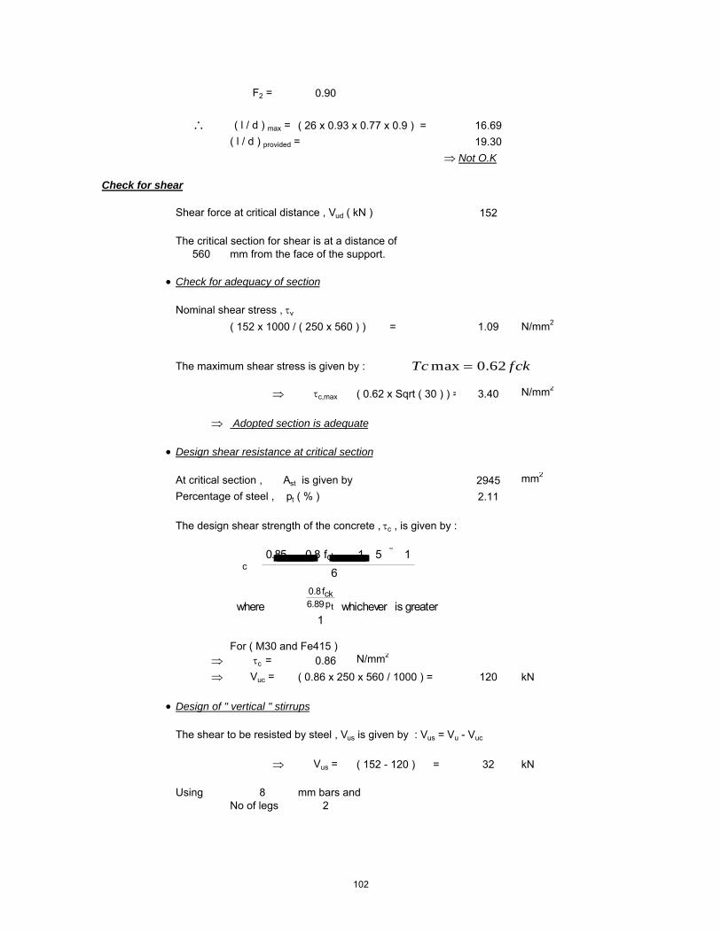
F2 = 0.90
∴ ( l / d ) max = ( 26 x 0.93 x 0.77 x 0.9 ) = 16.69( l / d ) provided = 19.30
⇒ Not O.K
Check for shear
Shear force at critical distance , Vud ( kN ) 152
The critical section for shear is at a distance of 560 mm from the face of the support.
• Check for adequacy of section
Nominal shear stress , τv
( 152 x 1000 / ( 250 x 560 ) ) = 1.09 N/mm2
The maximum shear stress is given by :
⇒ τc,max ( 0.62 x Sqrt ( 30 ) ) = 3.40 N/mm2
⇒ Adopted section is adequate
• Design shear resistance at critical section
At critical section , Ast is given by 2945 mm2
Percentage of steel , pt ( % ) 2.11
The design shear strength of the concrete , τc , is given by :
For ( M30 and Fe415 ) ⇒ τc = 0.86 N/mm2
⇒ Vuc = ( 0.86 x 250 x 560 / 1000 ) = 120 kN
• Design of " vertical " stirrups
The shear to be resisted by steel , Vus is given by : Vus = Vu - Vuc
⇒ Vus = ( 152 - 120 ) = 32 kN
Using 8 mm bars andNo of legs 2
�c �0.85� �0.8 fck��� 1 5 � 1�
6 �
where � ��0.8fck6.89pt
1whichever is greater
fckTc 62.0max =
102

Area of stirrups , Asv ( mm2 ) 101
⇒ required spacing sv ≤ ( 0.87 x 415 x 101 x 560 / ( 32 x 1000 ) )
⇒ Spacing , sv = 635 mm
Check whether τ v > 0.5 τ c
Nominal shear stress , τv ( N/mm2 ) 1.09Design shear stress , τc ( N/mm2 ) 0.86
τv > 0.5 τc Yes
The Code ( Cl. 26.5.1.6 ) specifies a minimum shear reinforcement to be provided in the form of stirrups in all beams where the calculated nominal shear stress τv
exceeds 0.5 τc. :
The maximum spacing of stirrups should also comply with the requirements mentioned above. For normal " vertical " stirrups, the requirement is
Code requirements for maximum spacing..
i) < ( 2.175 x 415 x 101 / 250 ) = 363 mmii) ≤ ( 0.75 x 559.5 ) = 420 mmiii) ≤ 300 mm 300 mmiv) ≤ ( 0.87 x 415 x 101 x 560 / ( 32 x 1000 ) ) = 635 mm
sv ��0.75 d300 mm
bfyAsv
tcsvWhenfyb
A
sv
sv
sv
175.2
5.087.0
4.0
=
==
103

Beam PB1 Mid Span
Design Parameters
Load Case 14 [1.5*(DL - EQX)]Grade of Concrete M30Grade of Steel Fe415Characteristic compressive strength of concrete , fck ( N/mm2 ) 30Characteristic yield strength of steel , fy ( N/mm2 ) 415Unit weight of concrete , γc ( kN/m3 ) 24Partial safety factor for concrete 1.5Exposure condition MildNominal Cover to exposure condition( mm ) 20
Dimensions of the beam
C/C Span of the beam , l , ( m ) 4.96Breadth of the beam , b ( mm ) 250Overall depth of the beam , D ( mm ) 600
Details of reinforcements
Diameter of tension reinforcement ( mm ) 25 Diameter of compression reinforcement ( mm ) 25Diameter of stirrups ( mm ) 8
Effective depth
Effective depth , d ( mm ) ( 600-20-8-25/2 ) = 560
Design Moment, Shear Force
The moments and shears given below are taken from the STAAD.Pro 2004 output file.The partial factors of safety are already incorporated into the analysis.
Torsional Moment 0 kN-mBending Moment Mu(kN-m) 289Equivalent Bending Moment , Me ( kNm ) 289Shear force at critical distance , Vud ( kN ) 179Equivalent Shear (kN) 179
Singly reinforced or doubly reinforced section ?
The limiting moment of resistance , Mu,lim is given by
The limiting percentage of steel , pt,lim is given by
SectiontheofdepthEffectivedAxisNeutralofdepthLimitingxu
SectiontheofBreadthbWhere
0.416xu*d
bxu*0.362fckMulim
max
maxmax
==
=
=
104

The area of steel for a singly reinforced section with width , b and depth , d and ultimate moment , Mu is given by :
For ( M30 and Fe415 )
xu,max / d = 0.48
⇒ Mu,lim = ( 0.1389 x 30 x 250 x 559.5^2 / 1000000 ) = 326.11 kNm
⇒ pt,lim = ( 41.3 x 30 / 415 x 0.48 ) = 1.433
If Mu > Mu,lim , the section has to be i) get increased by depth or width ( preferably depth )ii) doubly reinforced
If Mu < Mu,lim , the section can be designed as singly reinforced.
Check for the type of section
Mu = 289.00 kNmMu,lim = 326.11 kNm
⇒ Section can be designed as singly reinforced.
Determining A st
• Considering a ' balanced section ' ( xu = xu,max )Ast = Ast,lim + ΔAst
where Ast,lim = pt,lim / 100 ( b x d )
⇒ Ast,lim ( 1.433 / 100 x 250 x 559.5 ) = 2004 mm2
• Assuming 25 mm bars for compression steel,
d' ≈ ( 20 mm clear cover + 8 mm stirrup + 25 / 2 ) = 40.5 mm
Mu,lim � 0.1389 fck b d2
steelofstrengthticCharcterisfyconcreteofstrengtheCompressivticCharcterisfckWhere
dxu*
fyfck*41.61Pt max
lim
==
=
2
598.42100
bdMuRWhere
fR
fyfckx
bdAstxPt
ck
=
=
105

Mu = 0.87*fy**Ast*d(1-(Ast*fy)/b*d*fck)
Ast Reqd = 1725 mm2
∴ No of tension bars required ( # )( 1725 / ( Pi / 4 x 25^2 ) = 4.00
Actual percentage of steel , pt ( % )( 4 x Pi / 4 x 25 ^2 / 250 / 560 x 100 ) = 1.40
Actual area of steel , Ast ( mm2 )( 4 x Pi / 4 x 25 ^2 ) = 1963
Determining A sc
The compression steel , Asc , is given by
or
where fsc is the stress in compression steel.
The values of fsc ( in MPa units ) at xu = xu,max for variousd' / d ratios and different grades of compression steel are given in the table below.
• Assuming xu = xu,max , for d' / d = ( 40.5 / 559.5 ) = 0.072From the above table : by interpolation
Design Check
• To ensure xu ≤ xu,max , it suffices to establish pc ≥ pc*
�Ast ��Mu Mu,lim�0.87 fy�d d'
�pt100
�R Rlim
0.87 fy�1 d'd
Asc ��0.87 fy���Ast
fsc 0.447 fck
pc �0.87 fy�pt pt,lim
fsc 0.447 fck
Grade of steel d'd
0.05 0.10 0.15 0.20Fe250 217.5 217.5 217.5 217.5Fe415 355.1 351.9 342.4 329.2Fe500 423.9 411.3 395.1 370.3
106
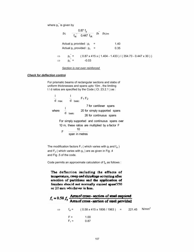
where pc* is given by
Actual pt provided : pt = 1.40Actual pc provided : pc = 0.35
⇒ pc* = ( 0.87 x 415 x ( 1.404 - 1.433 ) / ( 354.73 - 0.447 x 30 ) )
⇒ pc* = -0.03
Section is not over reinforced
Check for deflection control
For prismatic beams of rectangular sections and slabs of uniform thicknesses and spans upto 10m , the limiting l / d ratios are specified by the Code ( Cl. 23.2.1 ) as :
The modification factors F1 ( which varies with pt and fst )and F2 ( which varies with pc ) are as given in Fig .4 and Fig .5 of the code.
Code permits an approximate calculation of fst as follows :
⇒ fst = ( 0.58 x 415 x 1806 / 1963 ) = 221.45 N/mm2
F = 1.00F1 = 0.87
pc �
0.87 fy�fsc 0.447 fck��pt pt,lim
�ld�max
��ld�basic
F1 F2
where �ld�basic
���������7 for cantilever spans20 for simply supported spans
26 for continuous spans
For simply supported and continuous spans over10 m, these ratios are multiplied by a factor F
F �10
span in metres
107

F2 = 0.90
∴ ( l / d ) max = ( 26 x 1 x 0.87 x 0.9 ) = 20.28( l / d ) provided = 8.87
⇒ Hence O.K.
Check for shear
Shear force at critical distance , Vud ( kN ) 179
The critical section for shear is at a distance of 560 mm from the face of the support.
• Check for adequacy of section
Nominal shear stress , τv
( 179 x 1000 / ( 250 x 560 ) ) = 1.28 N/mm2
The maximum shear stress is given by :
⇒ τc,max ( 0.62 x Sqrt ( 30 ) ) = 3.40 N/mm2
⇒ Adopted section is adequate
• Design shear resistance at critical section
At critical section , Ast is given by 1963 mm2
Percentage of steel , pt ( % ) 1.40
The design shear strength of the concrete , τc , is given by :
For ( M30 and Fe415 ) ⇒ τc = 0.74 N/mm2
⇒ Vuc = ( 0.74 x 250 x 560 / 1000 ) = 104 kN
• Design of " vertical " stirrups
The shear to be resisted by steel , Vus is given by : Vus = Vu - Vuc
⇒ Vus = ( 179 - 104 ) = 75 kN
Using 8 mm bars andNo of legs 2
�c �0.85� �0.8 fck��� 1 5 � 1�
6 �
where � ��0.8fck6.89pt
1whichever is greater
fckTc 62.0max =
108

Area of stirrups , Asv ( mm2 ) 101
⇒ required spacing sv ≤ ( 0.87 x 415 x 101 x 560 / ( 74.88 x 1000 ) )
⇒ Spacing , sv = 271 mm
Check whether τ v > 0.5 τ c
Nominal shear stress , τv ( N/mm2 ) 1.28Design shear stress , τc ( N/mm2 ) 0.74
τv > 0.5 τc Yes
The Code ( Cl. 26.5.1.6 ) specifies a minimum shear reinforcement to be provided in the form of stirrups in all beams where the calculated nominal shear stress τv
exceeds 0.5 τc. :
The maximum spacing of stirrups should also comply with the requirements mentioned above. For normal " vertical " stirrups, the requirement is
Code requirements for maximum spacing..
i) < ( 2.175 x 415 x 101 / 250 ) = 363 mmii) ≤ ( 0.75 x 559.5 ) = 420 mmiii) ≤ 300 mm 300 mmiv) ≤ ( 0.87 x 415 x 101 x 560 / ( 74.88 x 1000 ) ) = 271 mm
sv ��0.75 d300 mm
bfyAsv
tcsvWhenfyb
A
sv
sv
sv
175.2
5.087.0
4.0
=
==
109

Beam B1 Support
Design Parameters
Load Case 13 [1.5*(DL + EQX)]Grade of Concrete M30Grade of Steel Fe415Characteristic compressive strength of concrete , fck ( N/mm2 ) 30Characteristic yield strength of steel , fy ( N/mm2 ) 415Unit weight of concrete , γc ( kN/m3 ) 24Partial safety factor for concrete 1.5Exposure condition MildNominal Cover to exposure condition( mm ) 20
Dimensions of the beam
C/C Span of the beam , l , ( m ) 4.96Breadth of the beam , b ( mm ) 400Overall depth of the beam , D ( mm ) 900
Details of reinforcements
Diameter of tension reinforcement ( mm ) 25 Diameter of compression reinforcement ( mm ) 25Diameter of stirrups ( mm ) 8
Effective depth
Effective depth , d ( mm ) ( 900-20-8-25/2 ) = 860
Design Moment, Shear Force
The moments and shears given below are taken from the STAAD.Pro 2004 output file.The partial factors of safety are already incorporated into the analysis.
Torsional Moment 150 kN-mBending Moment Mu(kN-m) 1053Equivalent Bending Moment , Me ( kNm ) 1340Shear force at critical distance , Vud ( kN ) 233Equivalent Shear (kN) 833
Singly reinforced or doubly reinforced section ?
The limiting moment of resistance , Mu,lim is given by
The limiting percentage of steel , pt,lim is given by
SectiontheofdepthEffectivedAxisNeutralofdepthLimitingxu
SectiontheofBreadthbWhere
0.416xu*d
bxu*0.362fckMulim
max
maxmax
==
=
=
110

The area of steel for a singly reinforced section with width , b and depth , d and ultimate moment , Mu is given by :
For ( M30 and Fe415 )
xu,max / d = 0.48
⇒ Mu,lim = ( 0.1389 x 30 x 400 x 859.5^2 / 1000000 ) = 1,231.33 kNm
⇒ pt,lim = ( 41.3 x 30 / 415 x 0.48 ) = 1.433
If Mu > Mu,lim , the section has to be i) get increased by depth or width ( preferably depth )ii) doubly reinforced
If Mu < Mu,lim , the section can be designed as singly reinforced.
Check for the type of section
Mu = 1,339.76 kNmMu,lim = 1,231.33 kNm
⇒
Determining A st
• Considering a ' balanced section ' ( xu = xu,max )Ast = Ast,lim + ΔAst
where Ast,lim = pt,lim / 100 ( b x d )
⇒ Ast,lim ( 1.433 / 100 x 400 x 859.5 ) = 4927 mm2
• Assuming 25 mm bars for compression steel,
d' ≈ ( 20 mm clear cover + 8 mm stirrup + 25 / 2 ) = 40.5 mm
Section cannot be designed as singly reinforced. Doubly Reinforced Section Needed
Mu,lim � 0.1389 fck b d2
steelofstrengthticCharcterisfyconcreteofstrengtheCompressivticCharcterisfckWhere
dxu*
fyfck*41.61Pt max
lim
==
=
2
598.42100
bdMuRWhere
fR
fyfckx
bdAstxPt
ck
=
=
111

Mu = 0.87*fy**Ast*d(1-(Ast*fy)/b*d*fck)
Ast Reqd = 5562 mm2
∴ No of tension bars required ( # )( 5562 / ( Pi / 4 x 25^2 ) = 12.00
Actual percentage of steel , pt ( % )( 12 x Pi / 4 x 25 ^2 / 400 / 860 x 100 ) = 1.71
Actual area of steel , Ast ( mm2 )( 12 x Pi / 4 x 25 ^2 ) = 5890
Determining A sc
The compression steel , Asc , is given by
or
where fsc is the stress in compression steel.
The values of fsc ( in MPa units ) at xu = xu,max for variousd' / d ratios and different grades of compression steel are given in the table below.
• Assuming xu = xu,max , for d' / d = ( 40.5 / 859.5 ) = 0.047From the above table : by interpolation
Design Check
• To ensure xu ≤ xu,max , it suffices to establish pc ≥ pc*
�Ast ��Mu Mu,lim�0.87 fy�d d'
�pt100
�R Rlim
0.87 fy�1 d'd
Asc ��0.87 fy���Ast
fsc 0.447 fck
pc �0.87 fy�pt pt,lim
fsc 0.447 fck
Grade of steel d'd
0.05 0.10 0.15 0.20Fe250 217.5 217.5 217.5 217.5Fe415 355.1 351.9 342.4 329.2Fe500 423.9 411.3 395.1 370.3
112

where pc* is given by
Actual pt provided : pt = 1.71Actual pc provided : pc = 0.14
⇒ pc* = ( 0.87 x 415 x ( 1.713 - 1.433 ) / ( 354.98 - 0.447 x 30 ) )
⇒ pc* = 0.30
Section is not over reinforced
Check for deflection control
For prismatic beams of rectangular sections and slabs of uniform thicknesses and spans upto 10m , the limiting l / d ratios are specified by the Code ( Cl. 23.2.1 ) as :
The modification factors F1 ( which varies with pt and fst )and F2 ( which varies with pc ) are as given in Fig .4 and Fig .5 of the code.
Code permits an approximate calculation of fst as follows :
⇒ fst = ( 0.58 x 415 x 5294 / 5890 ) = 216.31 N/mm2
F = 1.00F1 = 0.79
pc �
0.87 fy�fsc 0.447 fck��pt pt,lim
�ld�max
��ld�basic
F1 F2
where �ld�basic
���������7 for cantilever spans20 for simply supported spans
26 for continuous spans
For simply supported and continuous spans over10 m, these ratios are multiplied by a factor F
F �10
span in metres
113
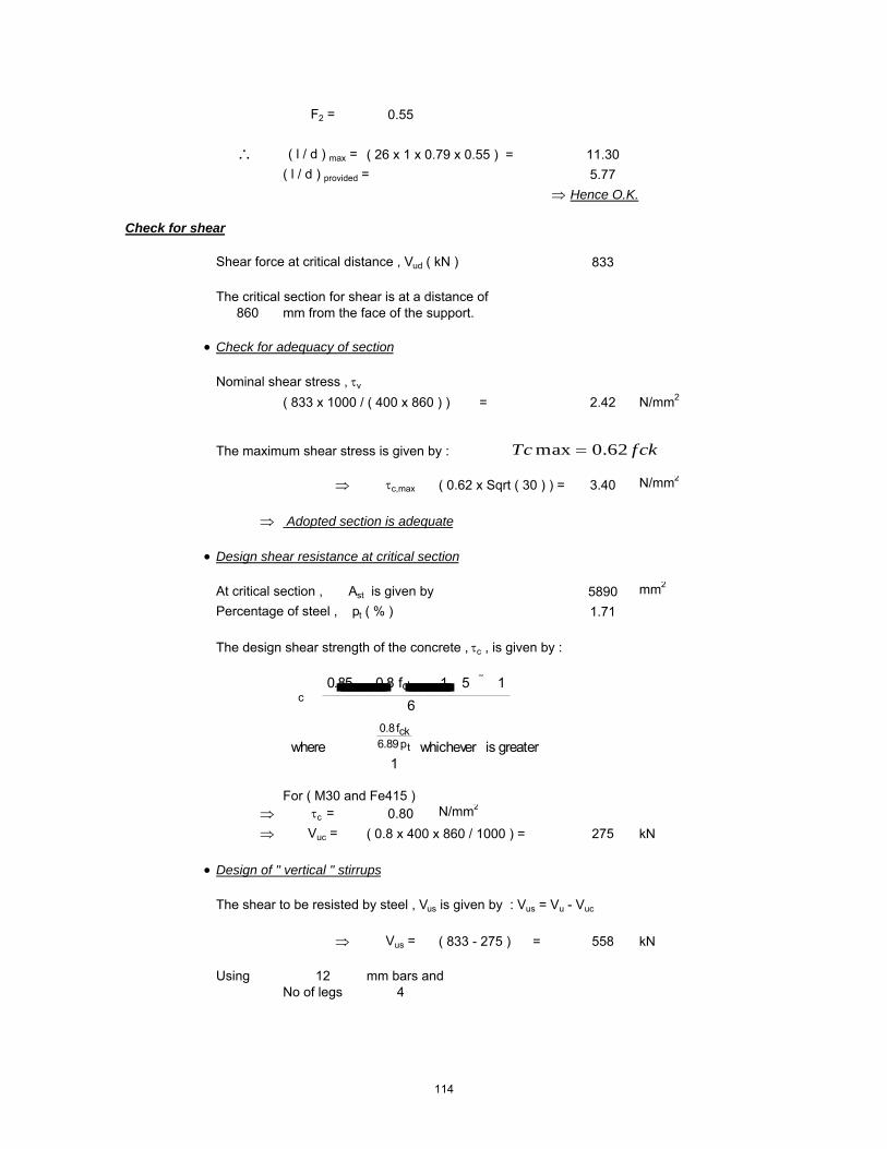
F2 = 0.55
∴ ( l / d ) max = ( 26 x 1 x 0.79 x 0.55 ) = 11.30( l / d ) provided = 5.77
⇒ Hence O.K.
Check for shear
Shear force at critical distance , Vud ( kN ) 833
The critical section for shear is at a distance of 860 mm from the face of the support.
• Check for adequacy of section
Nominal shear stress , τv
( 833 x 1000 / ( 400 x 860 ) ) = 2.42 N/mm2
The maximum shear stress is given by :
⇒ τc,max ( 0.62 x Sqrt ( 30 ) ) = 3.40 N/mm2
⇒ Adopted section is adequate
• Design shear resistance at critical section
At critical section , Ast is given by 5890 mm2
Percentage of steel , pt ( % ) 1.71
The design shear strength of the concrete , τc , is given by :
For ( M30 and Fe415 ) ⇒ τc = 0.80 N/mm2
⇒ Vuc = ( 0.8 x 400 x 860 / 1000 ) = 275 kN
• Design of " vertical " stirrups
The shear to be resisted by steel , Vus is given by : Vus = Vu - Vuc
⇒ Vus = ( 833 - 275 ) = 558 kN
Using 12 mm bars andNo of legs 4
�c �0.85� �0.8 fck��� 1 5 � 1�
6 �
where � ��0.8fck6.89pt
1whichever is greater
fckTc 62.0max =
114

Area of stirrups , Asv ( mm2 ) 452
⇒ required spacing sv ≤ ( 0.87 x 415 x 452 x 860 / ( 558.2 x 1000 ) )
⇒ Spacing , sv = 251 mm
Check whether τ v > 0.5 τ c
Nominal shear stress , τv ( N/mm2 ) 2.42Design shear stress , τc ( N/mm2 ) 0.80
τv > 0.5 τc Yes
The Code ( Cl. 26.5.1.6 ) specifies a minimum shear reinforcement to be provided in the form of stirrups in all beams where the calculated nominal shear stress τv
exceeds 0.5 τc. :
The maximum spacing of stirrups should also comply with the requirements mentioned above. For normal " vertical " stirrups, the requirement is
Code requirements for maximum spacing..
i) < ( 2.175 x 415 x 452 / 400 ) = 1021 mmii) ≤ ( 0.75 x 859.5 ) = 645 mmiii) ≤ 300 mm 300 mmiv) ≤ ( 0.87 x 415 x 452 x 860 / ( 558.2 x 1000 ) ) = 251 mm
sv ��0.75 d300 mm
bfyAsv
tcsvWhenfyb
A
sv
sv
sv
175.2
5.087.0
4.0
=
==
115

Beam B1 Mid
Design Parameters
Load Case 13 [1.5*(DL + EQX)]Grade of Concrete M30Grade of Steel Fe415Characteristic compressive strength of concrete , fck ( N/mm2 ) 30Characteristic yield strength of steel , fy ( N/mm2 ) 415Unit weight of concrete , γc ( kN/m3 ) 24Partial safety factor for concrete 1.5Exposure condition MildNominal Cover to exposure condition( mm ) 20
Dimensions of the beam
C/C Span of the beam , l , ( m ) 4.96Breadth of the beam , b ( mm ) 400Overall depth of the beam , D ( mm ) 900
Details of reinforcements
Diameter of tension reinforcement ( mm ) 25 Diameter of compression reinforcement ( mm ) 25Diameter of stirrups ( mm ) 8
Effective depth
Effective depth , d ( mm ) ( 900-20-8-25/2 ) = 860
Design Moment, Shear Force
The moments and shears given below are taken from the STAAD.Pro 2004 output file.The partial factors of safety are already incorporated into the analysis.
Torsional Moment 156 kN-mBending Moment Mu(kN-m) 331Equivalent Bending Moment , Me ( kNm ) 629Shear force at critical distance , Vud ( kN ) 218Equivalent Shear (kN) 842
Singly reinforced or doubly reinforced section ?
The limiting moment of resistance , Mu,lim is given by
The limiting percentage of steel , pt,lim is given by
SectiontheofdepthEffectivedAxisNeutralofdepthLimitingxu
SectiontheofBreadthbWhere
0.416xu*d
bxu*0.362fckMulim
max
maxmax
==
=
=
116
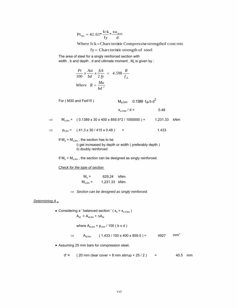
The area of steel for a singly reinforced section with width , b and depth , d and ultimate moment , Mu is given by :
For ( M30 and Fe415 )
xu,max / d = 0.48
⇒ Mu,lim = ( 0.1389 x 30 x 400 x 859.5^2 / 1000000 ) = 1,231.33 kNm
⇒ pt,lim = ( 41.3 x 30 / 415 x 0.48 ) = 1.433
If Mu > Mu,lim , the section has to be i) get increased by depth or width ( preferably depth )ii) doubly reinforced
If Mu < Mu,lim , the section can be designed as singly reinforced.
Check for the type of section
Mu = 629.24 kNmMu,lim = 1,231.33 kNm
⇒ Section can be designed as singly reinforced.
Determining A st
• Considering a ' balanced section ' ( xu = xu,max )Ast = Ast,lim + ΔAst
where Ast,lim = pt,lim / 100 ( b x d )
⇒ Ast,lim ( 1.433 / 100 x 400 x 859.5 ) = 4927 mm2
• Assuming 25 mm bars for compression steel,
d' ≈ ( 20 mm clear cover + 8 mm stirrup + 25 / 2 ) = 40.5 mm
Mu,lim � 0.1389 fck b d2
steelofstrengthticCharcterisfyconcreteofstrengtheCompressivticCharcterisfckWhere
dxu*
fyfck*41.61Pt max
lim
==
=
2
598.42100
bdMuRWhere
fR
fyfckx
bdAstxPt
ck
=
=
117

Mu = 0.87*fy**Ast*d(1-(Ast*fy)/b*d*fck)
Ast Reqd = 2227 mm2
∴ No of tension bars required ( # )( 2227 / ( Pi / 4 x 25^2 ) = 5.00
Actual percentage of steel , pt ( % )( 5 x Pi / 4 x 25 ^2 / 400 / 860 x 100 ) = 0.71
Actual area of steel , Ast ( mm2 )( 5 x Pi / 4 x 25 ^2 ) = 2454
Determining A sc
The compression steel , Asc , is given by
or
where fsc is the stress in compression steel.
The values of fsc ( in MPa units ) at xu = xu,max for variousd' / d ratios and different grades of compression steel are given in the table below.
• Assuming xu = xu,max , for d' / d = ( 40.5 / 859.5 ) = 0.047From the above table : by interpolation
Design Check
• To ensure xu ≤ xu,max , it suffices to establish pc ≥ pc*
�Ast ��Mu Mu,lim�0.87 fy�d d'
�pt100
�R Rlim
0.87 fy�1 d'd
Asc ��0.87 fy���Ast
fsc 0.447 fck
pc �0.87 fy�pt pt,lim
fsc 0.447 fck
Grade of steel d'd
0.05 0.10 0.15 0.20Fe250 217.5 217.5 217.5 217.5Fe415 355.1 351.9 342.4 329.2Fe500 423.9 411.3 395.1 370.3
118

where pc* is given by
Actual pt provided : pt = 0.71Actual pc provided : pc = 0.71
⇒ pc* = ( 0.87 x 415 x ( 0.714 - 1.433 ) / ( 354.98 - 0.447 x 30 ) )
⇒ pc* = -0.76
Section is not over reinforced
Check for deflection control
For prismatic beams of rectangular sections and slabs of uniform thicknesses and spans upto 10m , the limiting l / d ratios are specified by the Code ( Cl. 23.2.1 ) as :
The modification factors F1 ( which varies with pt and fst )and F2 ( which varies with pc ) are as given in Fig .4 and Fig .5 of the code.
Code permits an approximate calculation of fst as follows :
⇒ fst = ( 0.58 x 415 x 2891 / 2454 ) = 283.49 N/mm2
F = 1.00F1 = 1.08
pc �
0.87 fy�fsc 0.447 fck��pt pt,lim
�ld�max
��ld�basic
F1 F2
where �ld�basic
���������7 for cantilever spans20 for simply supported spans
26 for continuous spans
For simply supported and continuous spans over10 m, these ratios are multiplied by a factor F
F �10
span in metres
119

F2 = 1.16
∴ ( l / d ) max = ( 26 x 1 x 1.08 x 1.16 ) = 32.39( l / d ) provided = 5.77
⇒ Hence O.K.
Check for shear
Shear force at critical distance , Vud ( kN ) 842
The critical section for shear is at a distance of 860 mm from the face of the support.
• Check for adequacy of section
Nominal shear stress , τv
( 842 x 1000 / ( 400 x 860 ) ) = 2.45 N/mm2
The maximum shear stress is given by :
⇒ τc,max ( 0.62 x Sqrt ( 30 ) ) = 3.40 N/mm2
⇒ Adopted section is adequate
• Design shear resistance at critical section
At critical section , Ast is given by 2454 mm2
Percentage of steel , pt ( % ) 0.71
The design shear strength of the concrete , τc , is given by :
For ( M30 and Fe415 ) ⇒ τc = 0.57 N/mm2
⇒ Vuc = ( 0.57 x 400 x 860 / 1000 ) = 198 kN
• Design of " vertical " stirrups
The shear to be resisted by steel , Vus is given by : Vus = Vu - Vuc
⇒ Vus = ( 842 - 198 ) = 644 kN
Using 12 mm bars andNo of legs 4
�c �0.85� �0.8 fck��� 1 5 � 1�
6 �
where � ��0.8fck6.89pt
1whichever is greater
fckTc 62.0max =
120

Area of stirrups , Asv ( mm2 ) 452
⇒ required spacing sv ≤ ( 0.87 x 415 x 452 x 860 / ( 644.46 x 1000 ) )
⇒ Spacing , sv = 218 mm
Check whether τ v > 0.5 τ c
Nominal shear stress , τv ( N/mm2 ) 2.45Design shear stress , τc ( N/mm2 ) 0.57
τv > 0.5 τc Yes
The Code ( Cl. 26.5.1.6 ) specifies a minimum shear reinforcement to be provided in the form of stirrups in all beams where the calculated nominal shear stress τv
exceeds 0.5 τc. :
The maximum spacing of stirrups should also comply with the requirements mentioned above. For normal " vertical " stirrups, the requirement is
Code requirements for maximum spacing..
i) < ( 2.175 x 415 x 452 / 400 ) = 1021 mmii) ≤ ( 0.75 x 859.5 ) = 645 mmiii) ≤ 300 mm 300 mmiv) ≤ ( 0.87 x 415 x 452 x 860 / ( 644.46 x 1000 ) ) = 218 mm
sv ��0.75 d300 mm
bfyAsv
tcsvWhenfyb
A
sv
sv
sv
175.2
5.087.0
4.0
=
==
121

Beam B2 Support
Design Parameters
Load Case 14 [1.5*(DL - EQX)]Grade of Concrete M30Grade of Steel Fe415Characteristic compressive strength of concrete , fck ( N/mm2 ) 30Characteristic yield strength of steel , fy ( N/mm2 ) 415Unit weight of concrete , γc ( kN/m3 ) 24Partial safety factor for concrete 1.5Exposure condition MildNominal Cover to exposure condition( mm ) 20
Dimensions of the beam
C/C Span of the beam , l , ( m ) 10.80Breadth of the beam , b ( mm ) 800Overall depth of the beam , D ( mm ) 900
Details of reinforcements
Diameter of tension reinforcement ( mm ) 25 Diameter of compression reinforcement ( mm ) 25Diameter of stirrups ( mm ) 8
Effective depth
Effective depth , d ( mm ) ( 900-20-8-25/2 ) = 860
Design Moment, Shear Force
The moments and shears given below are taken from the STAAD.Pro 2004 output file.The partial factors of safety are already incorporated into the analysis.
Torsional Moment 125 kN-mBending Moment Mu(kN-m) 2065Equivalent Bending Moment , Me ( kNm ) 2221Shear force at critical distance , Vud ( kN ) 908Equivalent Shear (kN) 1158
Singly reinforced or doubly reinforced section ?
The limiting moment of resistance , Mu,lim is given by
The limiting percentage of steel , pt,lim is given by
SectiontheofdepthEffectivedAxisNeutralofdepthLimitingxu
SectiontheofBreadthbWhere
0.416xu*d
bxu*0.362fckMulim
max
maxmax
==
=
=
122

The area of steel for a singly reinforced section with width , b and depth , d and ultimate moment , Mu is given by :
For ( M30 and Fe415 )
xu,max / d = 0.48
⇒ Mu,lim = ( 0.1389 x 30 x 800 x 859.5^2 / 1000000 ) = 2,462.66 kNm
⇒ pt,lim = ( 41.3 x 30 / 415 x 0.48 ) = 1.433
If Mu > Mu,lim , the section has to be i) get increased by depth or width ( preferably depth )ii) doubly reinforced
If Mu < Mu,lim , the section can be designed as singly reinforced.
Check for the type of section
Mu = 2,221.25 kNmMu,lim = 2,462.66 kNm
⇒ Section can be designed as singly reinforced.
Determining A st
• Considering a ' balanced section ' ( xu = xu,max )Ast = Ast,lim + ΔAst
where Ast,lim = pt,lim / 100 ( b x d )
⇒ Ast,lim ( 1.433 / 100 x 800 x 859.5 ) = 9854 mm2
• Assuming 25 mm bars for compression steel,
d' ≈ ( 20 mm clear cover + 8 mm stirrup + 25 / 2 ) = 40.5 mm
Mu,lim � 0.1389 fck b d2
steelofstrengthticCharcterisfyconcreteofstrengtheCompressivticCharcterisfckWhere
dxu*
fyfck*41.61Pt max
lim
==
=
2
598.42100
bdMuRWhere
fR
fyfckx
bdAstxPt
ck
=
=
123

Mu = 0.87*fy**Ast*d(1-(Ast*fy)/b*d*fck)
Ast Reqd = 8670 mm2
∴ No of tension bars required ( # )( 8670 / ( Pi / 4 x 25^2 ) = 18.00
Actual percentage of steel , pt ( % )( 18 x Pi / 4 x 25 ^2 / 800 / 860 x 100 ) = 1.29
Actual area of steel , Ast ( mm2 )( 18 x Pi / 4 x 25 ^2 ) = 8836
Determining A sc
The compression steel , Asc , is given by
or
where fsc is the stress in compression steel.
The values of fsc ( in MPa units ) at xu = xu,max for variousd' / d ratios and different grades of compression steel are given in the table below.
• Assuming xu = xu,max , for d' / d = ( 40.5 / 859.5 ) = 0.047From the above table : by interpolation
Design Check
• To ensure xu ≤ xu,max , it suffices to establish pc ≥ pc*
�Ast ��Mu Mu,lim�0.87 fy�d d'
�pt100
�R Rlim
0.87 fy�1 d'd
Asc ��0.87 fy���Ast
fsc 0.447 fck
pc �0.87 fy�pt pt,lim
fsc 0.447 fck
Grade of steel d'd
0.05 0.10 0.15 0.20Fe250 217.5 217.5 217.5 217.5Fe415 355.1 351.9 342.4 329.2Fe500 423.9 411.3 395.1 370.3
124

where pc* is given by
Actual pt provided : pt = 1.29Actual pc provided : pc = 0.14
⇒ pc* = ( 0.87 x 415 x ( 1.285 - 1.433 ) / ( 354.98 - 0.447 x 30 ) )
⇒ pc* = -0.16
Section is not over reinforced
Check for deflection control
For prismatic beams of rectangular sections and slabs of uniform thicknesses and spans upto 10m , the limiting l / d ratios are specified by the Code ( Cl. 23.2.1 ) as :
The modification factors F1 ( which varies with pt and fst )and F2 ( which varies with pc ) are as given in Fig .4 and Fig .5 of the code.
Code permits an approximate calculation of fst as follows :
⇒ fst = ( 0.58 x 415 x 9037 / 8836 ) = 246.19 N/mm2
F = 0.93F1 = 0.85
pc �
0.87 fy�fsc 0.447 fck��pt pt,lim
�ld�max
��ld�basic
F1 F2
where �ld�basic
���������7 for cantilever spans20 for simply supported spans
26 for continuous spans
For simply supported and continuous spans over10 m, these ratios are multiplied by a factor F
F �10
span in metres
125

F2 = 0.55
∴ ( l / d ) max = ( 26 x 0.93 x 0.85 x 0.55 ) = 11.21( l / d ) provided = 12.57
⇒ Not O.K
Check for shear
Shear force at critical distance , Vud ( kN ) 1158
The critical section for shear is at a distance of 860 mm from the face of the support.
• Check for adequacy of section
Nominal shear stress , τv
( 1158 x 1000 / ( 800 x 860 ) ) = 1.68 N/mm2
The maximum shear stress is given by :
⇒ τc,max ( 0.62 x Sqrt ( 30 ) ) = 3.40 N/mm2
⇒ Adopted section is adequate
• Design shear resistance at critical section
At critical section , Ast is given by 8836 mm2
Percentage of steel , pt ( % ) 1.29
The design shear strength of the concrete , τc , is given by :
For ( M30 and Fe415 ) ⇒ τc = 0.72 N/mm2
⇒ Vuc = ( 0.72 x 800 x 860 / 1000 ) = 496 kN
• Design of " vertical " stirrups
The shear to be resisted by steel , Vus is given by : Vus = Vu - Vuc
⇒ Vus = ( 1158 - 496 ) = 662 kN
Using 12 mm bars andNo of legs 4
�c �0.85� �0.8 fck��� 1 5 � 1�
6 �
where � ��0.8fck6.89pt
1whichever is greater
fckTc 62.0max =
126

Area of stirrups , Asv ( mm2 ) 452
⇒ required spacing sv ≤ ( 0.87 x 415 x 452 x 860 / ( 662.45 x 1000 ) )
⇒ Spacing , sv = 212 mm
Check whether τ v > 0.5 τ c
Nominal shear stress , τv ( N/mm2 ) 1.68Design shear stress , τc ( N/mm2 ) 0.72
τv > 0.5 τc Yes
The Code ( Cl. 26.5.1.6 ) specifies a minimum shear reinforcement to be provided in the form of stirrups in all beams where the calculated nominal shear stress τv
exceeds 0.5 τc. :
The maximum spacing of stirrups should also comply with the requirements mentioned above. For normal " vertical " stirrups, the requirement is
Code requirements for maximum spacing..
i) < ( 2.175 x 415 x 452 / 800 ) = 510 mmii) ≤ ( 0.75 x 859.5 ) = 645 mmiii) ≤ 300 mm 300 mmiv) ≤ ( 0.87 x 415 x 452 x 860 / ( 662.45 x 1000 ) ) = 212 mm
sv ��0.75 d300 mm
bfyAsv
tcsvWhenfyb
A
sv
sv
sv
175.2
5.087.0
4.0
=
==
127
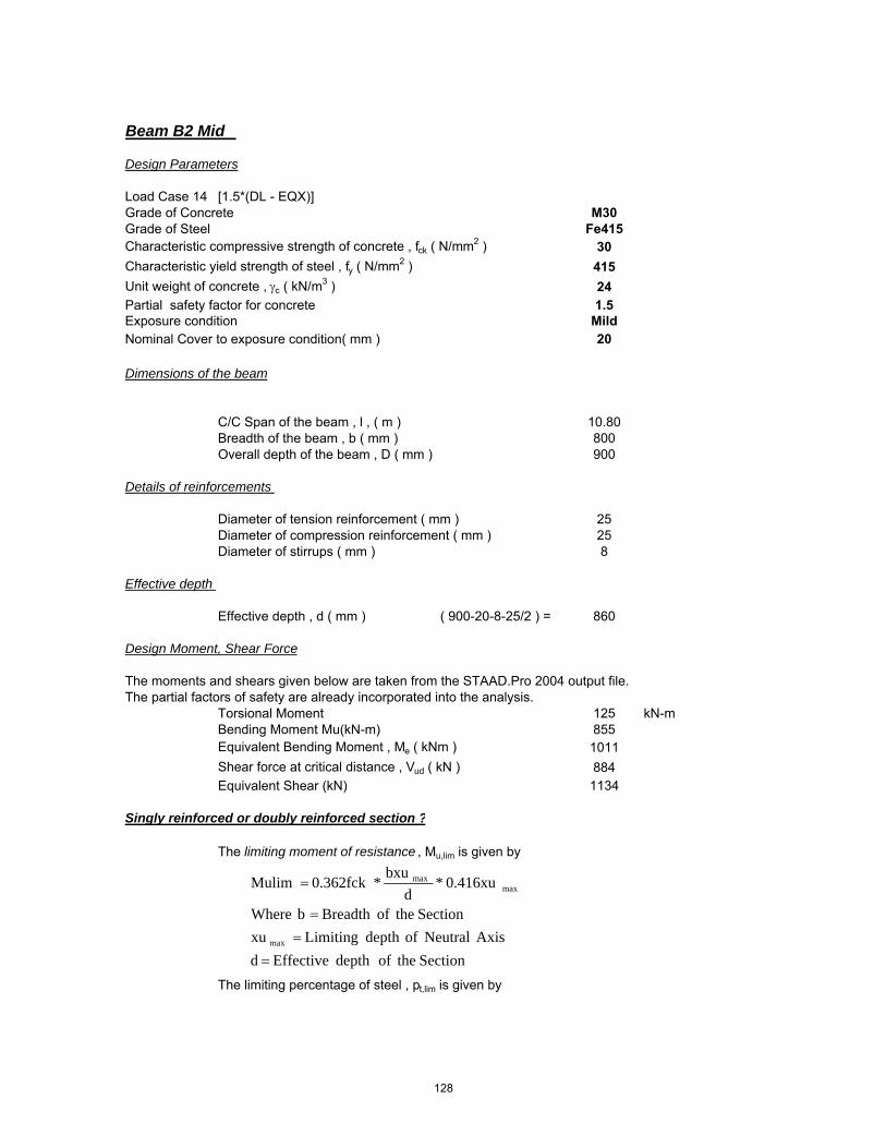
Beam B2 Mid
Design Parameters
Load Case 14 [1.5*(DL - EQX)]Grade of Concrete M30Grade of Steel Fe415Characteristic compressive strength of concrete , fck ( N/mm2 ) 30Characteristic yield strength of steel , fy ( N/mm2 ) 415Unit weight of concrete , γc ( kN/m3 ) 24Partial safety factor for concrete 1.5Exposure condition MildNominal Cover to exposure condition( mm ) 20
Dimensions of the beam
C/C Span of the beam , l , ( m ) 10.80Breadth of the beam , b ( mm ) 800Overall depth of the beam , D ( mm ) 900
Details of reinforcements
Diameter of tension reinforcement ( mm ) 25 Diameter of compression reinforcement ( mm ) 25Diameter of stirrups ( mm ) 8
Effective depth
Effective depth , d ( mm ) ( 900-20-8-25/2 ) = 860
Design Moment, Shear Force
The moments and shears given below are taken from the STAAD.Pro 2004 output file.The partial factors of safety are already incorporated into the analysis.
Torsional Moment 125 kN-mBending Moment Mu(kN-m) 855Equivalent Bending Moment , Me ( kNm ) 1011Shear force at critical distance , Vud ( kN ) 884Equivalent Shear (kN) 1134
Singly reinforced or doubly reinforced section ?
The limiting moment of resistance , Mu,lim is given by
The limiting percentage of steel , pt,lim is given by
SectiontheofdepthEffectivedAxisNeutralofdepthLimitingxu
SectiontheofBreadthbWhere
0.416xu*d
bxu*0.362fckMulim
max
maxmax
==
=
=
128

The area of steel for a singly reinforced section with width , b and depth , d and ultimate moment , Mu is given by :
For ( M30 and Fe415 )
xu,max / d = 0.48
⇒ Mu,lim = ( 0.1389 x 30 x 800 x 859.5^2 / 1000000 ) = 2,462.66 kNm
⇒ pt,lim = ( 41.3 x 30 / 415 x 0.48 ) = 1.433
If Mu > Mu,lim , the section has to be i) get increased by depth or width ( preferably depth )ii) doubly reinforced
If Mu < Mu,lim , the section can be designed as singly reinforced.
Check for the type of section
Mu = 1,011.25 kNmMu,lim = 2,462.66 kNm
⇒ Section can be designed as singly reinforced.
Determining A st
• Considering a ' balanced section ' ( xu = xu,max )Ast = Ast,lim + ΔAst
where Ast,lim = pt,lim / 100 ( b x d )
⇒ Ast,lim ( 1.433 / 100 x 800 x 859.5 ) = 9854 mm2
• Assuming 25 mm bars for compression steel,
d' ≈ ( 20 mm clear cover + 8 mm stirrup + 25 / 2 ) = 40.5 mm
Mu,lim � 0.1389 fck b d2
steelofstrengthticCharcterisfyconcreteofstrengtheCompressivticCharcterisfckWhere
dxu*
fyfck*41.61Pt max
lim
==
=
2
598.42100
bdMuRWhere
fR
fyfckx
bdAstxPt
ck
=
=
129

Mu = 0.87*fy**Ast*d(1-(Ast*fy)/b*d*fck)
Ast Reqd = 3506 mm2
∴ No of tension bars required ( # )( 3506 / ( Pi / 4 x 25^2 ) = 8.00
Actual percentage of steel , pt ( % )( 8 x Pi / 4 x 25 ^2 / 800 / 860 x 100 ) = 0.57
Actual area of steel , Ast ( mm2 )( 8 x Pi / 4 x 25 ^2 ) = 3927
Determining A sc
The compression steel , Asc , is given by
or
where fsc is the stress in compression steel.
The values of fsc ( in MPa units ) at xu = xu,max for variousd' / d ratios and different grades of compression steel are given in the table below.
• Assuming xu = xu,max , for d' / d = ( 40.5 / 859.5 ) = 0.047From the above table : by interpolation
Design Check
• To ensure xu ≤ xu,max , it suffices to establish pc ≥ pc*
�Ast ��Mu Mu,lim�0.87 fy�d d'
�pt100
�R Rlim
0.87 fy�1 d'd
Asc ��0.87 fy���Ast
fsc 0.447 fck
pc �0.87 fy�pt pt,lim
fsc 0.447 fck
Grade of steel d'd
0.05 0.10 0.15 0.20Fe250 217.5 217.5 217.5 217.5Fe415 355.1 351.9 342.4 329.2Fe500 423.9 411.3 395.1 370.3
130

where pc* is given by
Actual pt provided : pt = 0.57Actual pc provided : pc = 0.79
⇒ pc* = ( 0.87 x 415 x ( 0.571 - 1.433 ) / ( 354.98 - 0.447 x 30 ) )
⇒ pc* = -0.91
Section is not over reinforced
Check for deflection control
For prismatic beams of rectangular sections and slabs of uniform thicknesses and spans upto 10m , the limiting l / d ratios are specified by the Code ( Cl. 23.2.1 ) as :
The modification factors F1 ( which varies with pt and fst )and F2 ( which varies with pc ) are as given in Fig .4 and Fig .5 of the code.
Code permits an approximate calculation of fst as follows :
⇒ fst = ( 0.58 x 415 x 4945 / 3927 ) = 303.12 N/mm2
F = 0.93F1 = 1.18
pc �
0.87 fy�fsc 0.447 fck��pt pt,lim
�ld�max
��ld�basic
F1 F2
where �ld�basic
���������7 for cantilever spans20 for simply supported spans
26 for continuous spans
For simply supported and continuous spans over10 m, these ratios are multiplied by a factor F
F �10
span in metres
131

F2 = 1.19
∴ ( l / d ) max = ( 26 x 0.93 x 1.18 x 1.19 ) = 33.53( l / d ) provided = 12.57
⇒ Hence O.K.
Check for shear
Shear force at critical distance , Vud ( kN ) 1134
The critical section for shear is at a distance of 860 mm from the face of the support.
• Check for adequacy of section
Nominal shear stress , τv
( 1134 x 1000 / ( 800 x 860 ) ) = 1.65 N/mm2
The maximum shear stress is given by :
⇒ τc,max ( 0.62 x Sqrt ( 30 ) ) = 3.40 N/mm2
⇒ Adopted section is adequate
• Design shear resistance at critical section
At critical section , Ast is given by 3927 mm2
Percentage of steel , pt ( % ) 0.57
The design shear strength of the concrete , τc , is given by :
For ( M30 and Fe415 ) ⇒ τc = 0.52 N/mm2
⇒ Vuc = ( 0.52 x 800 x 860 / 1000 ) = 361 kN
• Design of " vertical " stirrups
The shear to be resisted by steel , Vus is given by : Vus = Vu - Vuc
⇒ Vus = ( 1134 - 361 ) = 773 kN
Using 12 mm bars andNo of legs 4
�c �0.85� �0.8 fck��� 1 5 � 1�
6 �
where � ��0.8fck6.89pt
1whichever is greater
fckTc 62.0max =
132

Area of stirrups , Asv ( mm2 ) 452
⇒ required spacing sv ≤ ( 0.87 x 415 x 452 x 860 / ( 773.14 x 1000 ) )
⇒ Spacing , sv = 182 mm
Check whether τ v > 0.5 τ c
Nominal shear stress , τv ( N/mm2 ) 1.65Design shear stress , τc ( N/mm2 ) 0.52
τv > 0.5 τc Yes
The Code ( Cl. 26.5.1.6 ) specifies a minimum shear reinforcement to be provided in the form of stirrups in all beams where the calculated nominal shear stress τv
exceeds 0.5 τc. :
The maximum spacing of stirrups should also comply with the requirements mentioned above. For normal " vertical " stirrups, the requirement is
Code requirements for maximum spacing..
i) < ( 2.175 x 415 x 452 / 800 ) = 510 mmii) ≤ ( 0.75 x 859.5 ) = 645 mmiii) ≤ 300 mm 300 mmiv) ≤ ( 0.87 x 415 x 452 x 860 / ( 773.14 x 1000 ) ) = 182 mm
sv ��0.75 d300 mm
bfyAsv
tcsvWhenfyb
A
sv
sv
sv
175.2
5.087.0
4.0
=
==
133

Beam B2A Support
Design Parameters
Load Case 15 [1.5*(DL + EQZ)]Grade of Concrete M30Grade of Steel Fe415Characteristic compressive strength of concrete , fck ( N/mm2 ) 30Characteristic yield strength of steel , fy ( N/mm2 ) 415Unit weight of concrete , γc ( kN/m3 ) 24Partial safety factor for concrete 1.5Exposure condition MildNominal Cover to exposure condition( mm ) 20
Dimensions of the beam
C/C Span of the beam , l , ( m ) 4.96Breadth of the beam , b ( mm ) 550Overall depth of the beam , D ( mm ) 900
Details of reinforcements
Diameter of tension reinforcement ( mm ) 25 Diameter of compression reinforcement ( mm ) 25Diameter of stirrups ( mm ) 8
Effective depth
Effective depth , d ( mm ) ( 900-20-8-25/2 ) = 860
Design Moment, Shear Force
The moments and shears given below are taken from the STAAD.Pro 2004 output file.The partial factors of safety are already incorporated into the analysis.
Torsional Moment 163 kN-mBending Moment Mu(kN-m) 1428Equivalent Bending Moment , Me ( kNm ) 1681Shear force at critical distance , Vud ( kN ) 199Equivalent Shear (kN) 673
Singly reinforced or doubly reinforced section ?
The limiting moment of resistance , Mu,lim is given by
The limiting percentage of steel , pt,lim is given by
SectiontheofdepthEffectivedAxisNeutralofdepthLimitingxu
SectiontheofBreadthbWhere
0.416xu*d
bxu*0.362fckMulim
max
maxmax
==
=
=
134

The area of steel for a singly reinforced section with width , b and depth , d and ultimate moment , Mu is given by :
For ( M30 and Fe415 )
xu,max / d = 0.48
⇒ Mu,lim = ( 0.1389 x 30 x 550 x 859.5^2 / 1000000 ) = 1,693.08 kNm
⇒ pt,lim = ( 41.3 x 30 / 415 x 0.48 ) = 1.433
If Mu > Mu,lim , the section has to be i) get increased by depth or width ( preferably depth )ii) doubly reinforced
If Mu < Mu,lim , the section can be designed as singly reinforced.
Check for the type of section
Mu = 1,680.78 kNmMu,lim = 1,693.08 kNm
⇒ Section can be designed as singly reinforced.
Determining A st
• Considering a ' balanced section ' ( xu = xu,max )Ast = Ast,lim + ΔAst
where Ast,lim = pt,lim / 100 ( b x d )
⇒ Ast,lim ( 1.433 / 100 x 550 x 859.5 ) = 6774 mm2
• Assuming 25 mm bars for compression steel,
d' ≈ ( 20 mm clear cover + 8 mm stirrup + 25 / 2 ) = 40.5 mm
Mu,lim � 0.1389 fck b d2
steelofstrengthticCharcterisfyconcreteofstrengtheCompressivticCharcterisfckWhere
dxu*
fyfck*41.61Pt max
lim
==
=
2
598.42100
bdMuRWhere
fR
fyfckx
bdAstxPt
ck
=
=
135

Mu = 0.87*fy**Ast*d(1-(Ast*fy)/b*d*fck)
Ast Reqd = 6749 mm2
∴ No of tension bars required ( # )( 6749 / ( Pi / 4 x 25^2 ) = 14.00
Actual percentage of steel , pt ( % )( 14 x Pi / 4 x 25 ^2 / 550 / 860 x 100 ) = 1.45
Actual area of steel , Ast ( mm2 )( 14 x Pi / 4 x 25 ^2 ) = 6872
Determining A sc
The compression steel , Asc , is given by
or
where fsc is the stress in compression steel.
The values of fsc ( in MPa units ) at xu = xu,max for variousd' / d ratios and different grades of compression steel are given in the table below.
• Assuming xu = xu,max , for d' / d = ( 40.5 / 859.5 ) = 0.047From the above table : by interpolation
Design Check
• To ensure xu ≤ xu,max , it suffices to establish pc ≥ pc*
�Ast ��Mu Mu,lim�0.87 fy�d d'
�pt100
�R Rlim
0.87 fy�1 d'd
Asc ��0.87 fy���Ast
fsc 0.447 fck
pc �0.87 fy�pt pt,lim
fsc 0.447 fck
Grade of steel d'd
0.05 0.10 0.15 0.20Fe250 217.5 217.5 217.5 217.5Fe415 355.1 351.9 342.4 329.2Fe500 423.9 411.3 395.1 370.3
136

where pc* is given by
Actual pt provided : pt = 1.45Actual pc provided : pc = 0.10
⇒ pc* = ( 0.87 x 415 x ( 1.454 - 1.433 ) / ( 354.98 - 0.447 x 30 ) )
⇒ pc* = 0.02
Section is not over reinforced
Check for deflection control
For prismatic beams of rectangular sections and slabs of uniform thicknesses and spans upto 10m , the limiting l / d ratios are specified by the Code ( Cl. 23.2.1 ) as :
The modification factors F1 ( which varies with pt and fst )and F2 ( which varies with pc ) are as given in Fig .4 and Fig .5 of the code.
Code permits an approximate calculation of fst as follows :
⇒ fst = ( 0.58 x 415 x 6733 / 6872 ) = 235.82 N/mm2
F = 1.00F1 = 0.82
pc �
0.87 fy�fsc 0.447 fck��pt pt,lim
�ld�max
��ld�basic
F1 F2
where �ld�basic
���������7 for cantilever spans20 for simply supported spans
26 for continuous spans
For simply supported and continuous spans over10 m, these ratios are multiplied by a factor F
F �10
span in metres
137

F2 = 0.44
∴ ( l / d ) max = ( 26 x 1 x 0.82 x 0.44 ) = 9.36( l / d ) provided = 5.77
⇒ Hence O.K.
Check for shear
Shear force at critical distance , Vud ( kN ) 673.18182
The critical section for shear is at a distance of 860 mm from the face of the support.
• Check for adequacy of section
Nominal shear stress , τv
( 673.181818181818 x 1000 / ( 550 x 860 ) ) 1.42 N/mm2
The maximum shear stress is given by :
⇒ τc,max ( 0.62 x Sqrt ( 30 ) ) = 3.40 N/mm2
⇒ Adopted section is adequate
• Design shear resistance at critical section
At critical section , Ast is given by 6872 mm2
Percentage of steel , pt ( % ) 1.45
The design shear strength of the concrete , τc , is given by :
For ( M30 and Fe415 ) ⇒ τc = 0.75 N/mm2
⇒ Vuc = ( 0.75 x 550 x 860 / 1000 ) = 356 kN
• Design of " vertical " stirrups
The shear to be resisted by steel , Vus is given by : Vus = Vu - Vuc
⇒ Vus = ( 673 - 356 ) = 317 kN
Using 12 mm bars andNo of legs 2
�c �0.85� �0.8 fck��� 1 5 � 1�
6 �
where � ��0.8fck6.89pt
1whichever is greater
fckTc 62.0max =
138
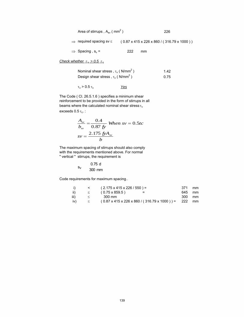
Area of stirrups , Asv ( mm2 ) 226
⇒ required spacing sv ≤ ( 0.87 x 415 x 226 x 860 / ( 316.79 x 1000 ) )
⇒ Spacing , sv = 222 mm
Check whether τ v > 0.5 τ c
Nominal shear stress , τv ( N/mm2 ) 1.42Design shear stress , τc ( N/mm2 ) 0.75
τv > 0.5 τc Yes
The Code ( Cl. 26.5.1.6 ) specifies a minimum shear reinforcement to be provided in the form of stirrups in all beams where the calculated nominal shear stress τv
exceeds 0.5 τc. :
The maximum spacing of stirrups should also comply with the requirements mentioned above. For normal " vertical " stirrups, the requirement is
Code requirements for maximum spacing..
i) < ( 2.175 x 415 x 226 / 550 ) = 371 mmii) ≤ ( 0.75 x 859.5 ) = 645 mmiii) ≤ 300 mm 300 mmiv) ≤ ( 0.87 x 415 x 226 x 860 / ( 316.79 x 1000 ) ) = 222 mm
sv ��0.75 d300 mm
bfyAsv
tcsvWhenfyb
A
sv
sv
sv
175.2
5.087.0
4.0
=
==
139

Beam B2A Mid
Design Parameters
Load Case 15 [1.5*(DL + EQZ)]Grade of Concrete M30Grade of Steel Fe415Characteristic compressive strength of concrete , fck ( N/mm2 ) 30Characteristic yield strength of steel , fy ( N/mm2 ) 415Unit weight of concrete , γc ( kN/m3 ) 24Partial safety factor for concrete 1.5Exposure condition MildNominal Cover to exposure condition( mm ) 20
Dimensions of the beam
C/C Span of the beam , l , ( m ) 4.96Breadth of the beam , b ( mm ) 550Overall depth of the beam , D ( mm ) 900
Details of reinforcements
Diameter of tension reinforcement ( mm ) 25 Diameter of compression reinforcement ( mm ) 25Diameter of stirrups ( mm ) 8
Effective depth
Effective depth , d ( mm ) ( 900-20-8-25/2 ) = 860
Design Moment, Shear Force
The moments and shears given below are taken from the STAAD.Pro 2004 output file.The partial factors of safety are already incorporated into the analysis.
Torsional Moment 163 kN-mBending Moment Mu(kN-m) 746Equivalent Bending Moment , Me ( kNm ) 999Shear force at critical distance , Vud ( kN ) 184Equivalent Shear (kN) 658
Singly reinforced or doubly reinforced section ?
The limiting moment of resistance , Mu,lim is given by
The limiting percentage of steel , pt,lim is given by
SectiontheofdepthEffectivedAxisNeutralofdepthLimitingxu
SectiontheofBreadthbWhere
0.416xu*d
bxu*0.362fckMulim
max
maxmax
==
=
=
140

The area of steel for a singly reinforced section with width , b and depth , d and ultimate moment , Mu is given by :
For ( M30 and Fe415 )
xu,max / d = 0.48
⇒ Mu,lim = ( 0.1389 x 30 x 550 x 859.5^2 / 1000000 ) = 1,693.08 kNm
⇒ pt,lim = ( 41.3 x 30 / 415 x 0.48 ) = 1.433
If Mu > Mu,lim , the section has to be i) get increased by depth or width ( preferably depth )ii) doubly reinforced
If Mu < Mu,lim , the section can be designed as singly reinforced.
Check for the type of section
Mu = 998.78 kNmMu,lim = 1,693.08 kNm
⇒ Section can be designed as singly reinforced.
Determining A st
• Considering a ' balanced section ' ( xu = xu,max )Ast = Ast,lim + ΔAst
where Ast,lim = pt,lim / 100 ( b x d )
⇒ Ast,lim ( 1.433 / 100 x 550 x 859.5 ) = 6774 mm2
• Assuming 25 mm bars for compression steel,
d' ≈ ( 20 mm clear cover + 8 mm stirrup + 25 / 2 ) = 40.5 mm
Mu,lim � 0.1389 fck b d2
steelofstrengthticCharcterisfyconcreteofstrengtheCompressivticCharcterisfckWhere
dxu*
fyfck*41.61Pt max
lim
==
=
2
598.42100
bdMuRWhere
fR
fyfckx
bdAstxPt
ck
=
=
141

Mu = 0.87*fy**Ast*d(1-(Ast*fy)/b*d*fck)
Ast Reqd = 3597 mm2
∴ No of tension bars required ( # )( 3597 / ( Pi / 4 x 25^2 ) = 8.00
Actual percentage of steel , pt ( % )( 8 x Pi / 4 x 25 ^2 / 550 / 860 x 100 ) = 0.83
Actual area of steel , Ast ( mm2 )( 8 x Pi / 4 x 25 ^2 ) = 3927
Determining A sc
The compression steel , Asc , is given by
or
where fsc is the stress in compression steel.
The values of fsc ( in MPa units ) at xu = xu,max for variousd' / d ratios and different grades of compression steel are given in the table below.
• Assuming xu = xu,max , for d' / d = ( 40.5 / 859.5 ) = 0.047From the above table : by interpolation
Design Check
• To ensure xu ≤ xu,max , it suffices to establish pc ≥ pc*
�Ast ��Mu Mu,lim�0.87 fy�d d'
�pt100
�R Rlim
0.87 fy�1 d'd
Asc ��0.87 fy���Ast
fsc 0.447 fck
pc �0.87 fy�pt pt,lim
fsc 0.447 fck
Grade of steel d'd
0.05 0.10 0.15 0.20Fe250 217.5 217.5 217.5 217.5Fe415 355.1 351.9 342.4 329.2Fe500 423.9 411.3 395.1 370.3
142

where pc* is given by
Actual pt provided : pt = 0.83Actual pc provided : pc = 0.62
⇒ pc* = ( 0.87 x 415 x ( 0.831 - 1.433 ) / ( 354.98 - 0.447 x 30 ) )
⇒ pc* = -0.64
Section is not over reinforced
Check for deflection control
For prismatic beams of rectangular sections and slabs of uniform thicknesses and spans upto 10m , the limiting l / d ratios are specified by the Code ( Cl. 23.2.1 ) as :
The modification factors F1 ( which varies with pt and fst )and F2 ( which varies with pc ) are as given in Fig .4 and Fig .5 of the code.
Code permits an approximate calculation of fst as follows :
⇒ fst = ( 0.58 x 415 x 4426 / 3927 ) = 271.31 N/mm2
F = 1.00F1 = 1.02
pc �
0.87 fy�fsc 0.447 fck��pt pt,lim
�ld�max
��ld�basic
F1 F2
where �ld�basic
���������7 for cantilever spans20 for simply supported spans
26 for continuous spans
For simply supported and continuous spans over10 m, these ratios are multiplied by a factor F
F �10
span in metres
143

F2 = 1.11
∴ ( l / d ) max = ( 26 x 1 x 1.02 x 1.11 ) = 29.37( l / d ) provided = 5.77
⇒ Hence O.K.
Check for shear
Shear force at critical distance , Vud ( kN ) 658.18182
The critical section for shear is at a distance of 860 mm from the face of the support.
• Check for adequacy of section
Nominal shear stress , τv
( 658.181818181818 x 1000 / ( 550 x 860 ) ) 1.39 N/mm2
The maximum shear stress is given by :
⇒ τc,max ( 0.62 x Sqrt ( 30 ) ) = 3.40 N/mm2
⇒ Adopted section is adequate
• Design shear resistance at critical section
At critical section , Ast is given by 3927 mm2
Percentage of steel , pt ( % ) 0.83
The design shear strength of the concrete , τc , is given by :
For ( M30 and Fe415 ) ⇒ τc = 0.61 N/mm2
⇒ Vuc = ( 0.61 x 550 x 860 / 1000 ) = 288 kN
• Design of " vertical " stirrups
The shear to be resisted by steel , Vus is given by : Vus = Vu - Vuc
⇒ Vus = ( 658 - 288 ) = 370 kN
Using 12 mm bars andNo of legs 2
�c �0.85� �0.8 fck��� 1 5 � 1�
6 �
where � ��0.8fck6.89pt
1whichever is greater
fckTc 62.0max =
144

Area of stirrups , Asv ( mm2 ) 226
⇒ required spacing sv ≤ ( 0.87 x 415 x 226 x 860 / ( 369.72 x 1000 ) )
⇒ Spacing , sv = 190 mm
Check whether τ v > 0.5 τ c
Nominal shear stress , τv ( N/mm2 ) 1.39Design shear stress , τc ( N/mm2 ) 0.61
τv > 0.5 τc Yes
The Code ( Cl. 26.5.1.6 ) specifies a minimum shear reinforcement to be provided in the form of stirrups in all beams where the calculated nominal shear stress τv
exceeds 0.5 τc. :
The maximum spacing of stirrups should also comply with the requirements mentioned above. For normal " vertical " stirrups, the requirement is
Code requirements for maximum spacing..
i) < ( 2.175 x 415 x 226 / 550 ) = 371 mmii) ≤ ( 0.75 x 859.5 ) = 645 mmiii) ≤ 300 mm 300 mmiv) ≤ ( 0.87 x 415 x 226 x 860 / ( 369.72 x 1000 ) ) = 190 mm
sv ��0.75 d300 mm
bfyAsv
tcsvWhenfyb
A
sv
sv
sv
175.2
5.087.0
4.0
=
==
145

Beam B3 Support
Design Parameters
Load Case 16 [1.5*(DL - EQZ)]Grade of Concrete M30Grade of Steel Fe415Characteristic compressive strength of concrete , fck ( N/mm2 ) 30Characteristic yield strength of steel , fy ( N/mm2 ) 415Unit weight of concrete , γc ( kN/m3 ) 24Partial safety factor for concrete 1.5Exposure condition MildNominal Cover to exposure condition( mm ) 20
Dimensions of the beam
C/C Span of the beam , l , ( m ) 8.36Breadth of the beam , b ( mm ) 300Overall depth of the beam , D ( mm ) 900
Details of reinforcements
Diameter of tension reinforcement ( mm ) 25 Diameter of compression reinforcement ( mm ) 25Diameter of stirrups ( mm ) 8
Effective depth
Effective depth , d ( mm ) ( 900-20-8-25/2 ) = 860
Design Moment, Shear Force
The moments and shears given below are taken from the STAAD.Pro 2004 output file.The partial factors of safety are already incorporated into the analysis.
Torsional Moment 11 kN-mBending Moment Mu(kN-m) 672Equivalent Bending Moment , Me ( kNm ) 698Shear force at critical distance , Vud ( kN ) 60Equivalent Shear (kN) 119
Singly reinforced or doubly reinforced section ?
The limiting moment of resistance , Mu,lim is given by
The limiting percentage of steel , pt,lim is given by
SectiontheofdepthEffectivedAxisNeutralofdepthLimitingxu
SectiontheofBreadthbWhere
0.416xu*d
bxu*0.362fckMulim
max
maxmax
==
=
=
146

The area of steel for a singly reinforced section with width , b and depth , d and ultimate moment , Mu is given by :
For ( M30 and Fe415 )
xu,max / d = 0.48
⇒ Mu,lim = ( 0.1389 x 30 x 300 x 859.5^2 / 1000000 ) = 923.50 kNm
⇒ pt,lim = ( 41.3 x 30 / 415 x 0.48 ) = 1.433
If Mu > Mu,lim , the section has to be i) get increased by depth or width ( preferably depth )ii) doubly reinforced
If Mu < Mu,lim , the section can be designed as singly reinforced.
Check for the type of section
Mu = 697.88 kNmMu,lim = 923.50 kNm
⇒ Section can be designed as singly reinforced.
Determining A st
• Considering a ' balanced section ' ( xu = xu,max )Ast = Ast,lim + ΔAst
where Ast,lim = pt,lim / 100 ( b x d )
⇒ Ast,lim ( 1.433 / 100 x 300 x 859.5 ) = 3695 mm2
• Assuming 25 mm bars for compression steel,
d' ≈ ( 20 mm clear cover + 8 mm stirrup + 25 / 2 ) = 40.5 mm
Mu,lim � 0.1389 fck b d2
steelofstrengthticCharcterisfyconcreteofstrengtheCompressivticCharcterisfckWhere
dxu*
fyfck*41.61Pt max
lim
==
=
2
598.42100
bdMuRWhere
fR
fyfckx
bdAstxPt
ck
=
=
147

Mu = 0.87*fy**Ast*d(1-(Ast*fy)/b*d*fck)
Ast Reqd = 2616 mm2
∴ No of tension bars required ( # )( 2616 / ( Pi / 4 x 25^2 ) = 6.00
Actual percentage of steel , pt ( % )( 6 x Pi / 4 x 25 ^2 / 300 / 860 x 100 ) = 1.14
Actual area of steel , Ast ( mm2 )( 6 x Pi / 4 x 25 ^2 ) = 2945
Determining A sc
The compression steel , Asc , is given by
or
where fsc is the stress in compression steel.
The values of fsc ( in MPa units ) at xu = xu,max for variousd' / d ratios and different grades of compression steel are given in the table below.
• Assuming xu = xu,max , for d' / d = ( 40.5 / 859.5 ) = 0.047From the above table : by interpolation
Design Check
• To ensure xu ≤ xu,max , it suffices to establish pc ≥ pc*
�Ast ��Mu Mu,lim�0.87 fy�d d'
�pt100
�R Rlim
0.87 fy�1 d'd
Asc ��0.87 fy���Ast
fsc 0.447 fck
pc �0.87 fy�pt pt,lim
fsc 0.447 fck
Grade of steel d'd
0.05 0.10 0.15 0.20Fe250 217.5 217.5 217.5 217.5Fe415 355.1 351.9 342.4 329.2Fe500 423.9 411.3 395.1 370.3
148

where pc* is given by
Actual pt provided : pt = 1.14Actual pc provided : pc = 0.38
⇒ pc* = ( 0.87 x 415 x ( 1.142 - 1.433 ) / ( 354.98 - 0.447 x 30 ) )
⇒ pc* = -0.31
Section is not over reinforced
Check for deflection control
For prismatic beams of rectangular sections and slabs of uniform thicknesses and spans upto 10m , the limiting l / d ratios are specified by the Code ( Cl. 23.2.1 ) as :
The modification factors F1 ( which varies with pt and fst )and F2 ( which varies with pc ) are as given in Fig .4 and Fig .5 of the code.
Code permits an approximate calculation of fst as follows :
⇒ fst = ( 0.58 x 415 x 2932 / 2945 ) = 239.63 N/mm2
F = 1.00F1 = 0.93
pc �
0.87 fy�fsc 0.447 fck��pt pt,lim
�ld�max
��ld�basic
F1 F2
where �ld�basic
���������7 for cantilever spans20 for simply supported spans
26 for continuous spans
For simply supported and continuous spans over10 m, these ratios are multiplied by a factor F
F �10
span in metres
149

F2 = 0.93
∴ ( l / d ) max = ( 26 x 1 x 0.93 x 0.93 ) = 22.37( l / d ) provided = 9.73
⇒ Hence O.K.
Check for shear
Shear force at critical distance , Vud ( kN ) 118.66667
The critical section for shear is at a distance of 860 mm from the face of the support.
• Check for adequacy of section
Nominal shear stress , τv
( 118.666666666667 x 1000 / ( 300 x 860 ) ) 0.46 N/mm2
The maximum shear stress is given by :
⇒ τc,max ( 0.62 x Sqrt ( 30 ) ) = 3.40 N/mm2
⇒ Adopted section is adequate
• Design shear resistance at critical section
At critical section , Ast is given by 2945 mm2
Percentage of steel , pt ( % ) 1.14
The design shear strength of the concrete , τc , is given by :
For ( M30 and Fe415 ) ⇒ τc = 0.69 N/mm2
⇒ Vuc = ( 0.69 x 300 x 860 / 1000 ) = 178 kN
• Design of " vertical " stirrups
The shear to be resisted by steel , Vus is given by : Vus = Vu - Vuc
⇒ Vus = ( 119 - 178 ) = -59 kN
Using 8 mm bars andNo of legs 2
�c �0.85� �0.8 fck��� 1 5 � 1�
6 �
where � ��0.8fck6.89pt
1whichever is greater
fckTc 62.0max =
150

Area of stirrups , Asv ( mm2 ) 101
⇒ required spacing sv ≤ ( 0.87 x 415 x 101 x 860 / ( -59.19 x 1000 ) )
⇒ Spacing , sv = -527 mm
Check whether τ v > 0.5 τ c
Nominal shear stress , τv ( N/mm2 ) 0.46Design shear stress , τc ( N/mm2 ) 0.69
τv > 0.5 τc Yes
The Code ( Cl. 26.5.1.6 ) specifies a minimum shear reinforcement to be provided in the form of stirrups in all beams where the calculated nominal shear stress τv
exceeds 0.5 τc. :
The maximum spacing of stirrups should also comply with the requirements mentioned above. For normal " vertical " stirrups, the requirement is
Code requirements for maximum spacing..
i) < ( 2.175 x 415 x 101 / 300 ) = 302 mmii) ≤ ( 0.75 x 859.5 ) = 645 mmiii) ≤ 300 mm 300 mmiv) ≤ ( 0.87 x 415 x 101 x 860 / ( -59.19 x 1000 ) ) = -527 mm
sv ��0.75 d300 mm
bfyAsv
tcsvWhenfyb
A
sv
sv
sv
175.2
5.087.0
4.0
=
==
151

Beam B3 Mid
Design Parameters
Load Case 16 [1.5*(DL - EQZ)]Grade of Concrete M30Grade of Steel Fe415Characteristic compressive strength of concrete , fck ( N/mm2 ) 30Characteristic yield strength of steel , fy ( N/mm2 ) 415Unit weight of concrete , γc ( kN/m3 ) 24Partial safety factor for concrete 1.5Exposure condition MildNominal Cover to exposure condition( mm ) 20
Dimensions of the beam
C/C Span of the beam , l , ( m ) 8.36Breadth of the beam , b ( mm ) 300Overall depth of the beam , D ( mm ) 900
Details of reinforcements
Diameter of tension reinforcement ( mm ) 20 Diameter of compression reinforcement ( mm ) 20Diameter of stirrups ( mm ) 8
Effective depth
Effective depth , d ( mm ) ( 900-20-8-20/2 ) = 862
Design Moment, Shear Force
The moments and shears given below are taken from the STAAD.Pro 2004 output file.The partial factors of safety are already incorporated into the analysis.
Torsional Moment 11 kN-mBending Moment Mu(kN-m) 303Equivalent Bending Moment , Me ( kNm ) 329Shear force at critical distance , Vud ( kN ) 47Equivalent Shear (kN) 106
Singly reinforced or doubly reinforced section ?
The limiting moment of resistance , Mu,lim is given by
The limiting percentage of steel , pt,lim is given by
SectiontheofdepthEffectivedAxisNeutralofdepthLimitingxu
SectiontheofBreadthbWhere
0.416xu*d
bxu*0.362fckMulim
max
maxmax
==
=
=
152

The area of steel for a singly reinforced section with width , b and depth , d and ultimate moment , Mu is given by :
For ( M30 and Fe415 )
xu,max / d = 0.48
⇒ Mu,lim = ( 0.1389 x 30 x 300 x 862^2 / 1000000 ) = 928.88 kNm
⇒ pt,lim = ( 41.3 x 30 / 415 x 0.48 ) = 1.433
If Mu > Mu,lim , the section has to be i) get increased by depth or width ( preferably depth )ii) doubly reinforced
If Mu < Mu,lim , the section can be designed as singly reinforced.
Check for the type of section
Mu = 328.88 kNmMu,lim = 928.88 kNm
⇒ Section can be designed as singly reinforced.
Determining A st
• Considering a ' balanced section ' ( xu = xu,max )Ast = Ast,lim + ΔAst
where Ast,lim = pt,lim / 100 ( b x d )
⇒ Ast,lim ( 1.433 / 100 x 300 x 862 ) = 3706 mm2
• Assuming 20 mm bars for compression steel,
d' ≈ ( 20 mm clear cover + 8 mm stirrup + 20 / 2 ) = 38 mm
Mu,lim � 0.1389 fck b d2
steelofstrengthticCharcterisfyconcreteofstrengtheCompressivticCharcterisfckWhere
dxu*
fyfck*41.61Pt max
lim
==
=
2
598.42100
bdMuRWhere
fR
fyfckx
bdAstxPt
ck
=
=
153

Mu = 0.87*fy**Ast*d(1-(Ast*fy)/b*d*fck)
Ast Reqd = 1124 mm2
∴ No of tension bars required ( # )( 1124 / ( Pi / 4 x 20^2 ) = 4.00
Actual percentage of steel , pt ( % )( 4 x Pi / 4 x 20 ^2 / 300 / 862 x 100 ) = 0.49
Actual area of steel , Ast ( mm2 )( 4 x Pi / 4 x 20 ^2 ) = 1257
Determining A sc
The compression steel , Asc , is given by
or
where fsc is the stress in compression steel.
The values of fsc ( in MPa units ) at xu = xu,max for variousd' / d ratios and different grades of compression steel are given in the table below.
• Assuming xu = xu,max , for d' / d = ( 38 / 862 ) = 0.044From the above table : by interpolation
Design Check
• To ensure xu ≤ xu,max , it suffices to establish pc ≥ pc*
�Ast ��Mu Mu,lim�0.87 fy�d d'
�pt100
�R Rlim
0.87 fy�1 d'd
Asc ��0.87 fy���Ast
fsc 0.447 fck
pc �0.87 fy�pt pt,lim
fsc 0.447 fck
Grade of steel d'd
0.05 0.10 0.15 0.20Fe250 217.5 217.5 217.5 217.5Fe415 355.1 351.9 342.4 329.2Fe500 423.9 411.3 395.1 370.3
154

where pc* is given by
Actual pt provided : pt = 0.49Actual pc provided : pc = 0.85
⇒ pc* = ( 0.87 x 415 x ( 0.486 - 1.433 ) / ( 354.8 - 0.447 x 30 ) )
⇒ pc* = -1.00
Section is not over reinforced
Check for deflection control
For prismatic beams of rectangular sections and slabs of uniform thicknesses and spans upto 10m , the limiting l / d ratios are specified by the Code ( Cl. 23.2.1 ) as :
The modification factors F1 ( which varies with pt and fst )and F2 ( which varies with pc ) are as given in Fig .4 and Fig .5 of the code.
Code permits an approximate calculation of fst as follows :
⇒ fst = ( 0.58 x 415 x 1689 / 1257 ) = 323.54 N/mm2
F = 1.00F1 = 1.23
pc �
0.87 fy�fsc 0.447 fck��pt pt,lim
�ld�max
��ld�basic
F1 F2
where �ld�basic
���������7 for cantilever spans20 for simply supported spans
26 for continuous spans
For simply supported and continuous spans over10 m, these ratios are multiplied by a factor F
F �10
span in metres
155
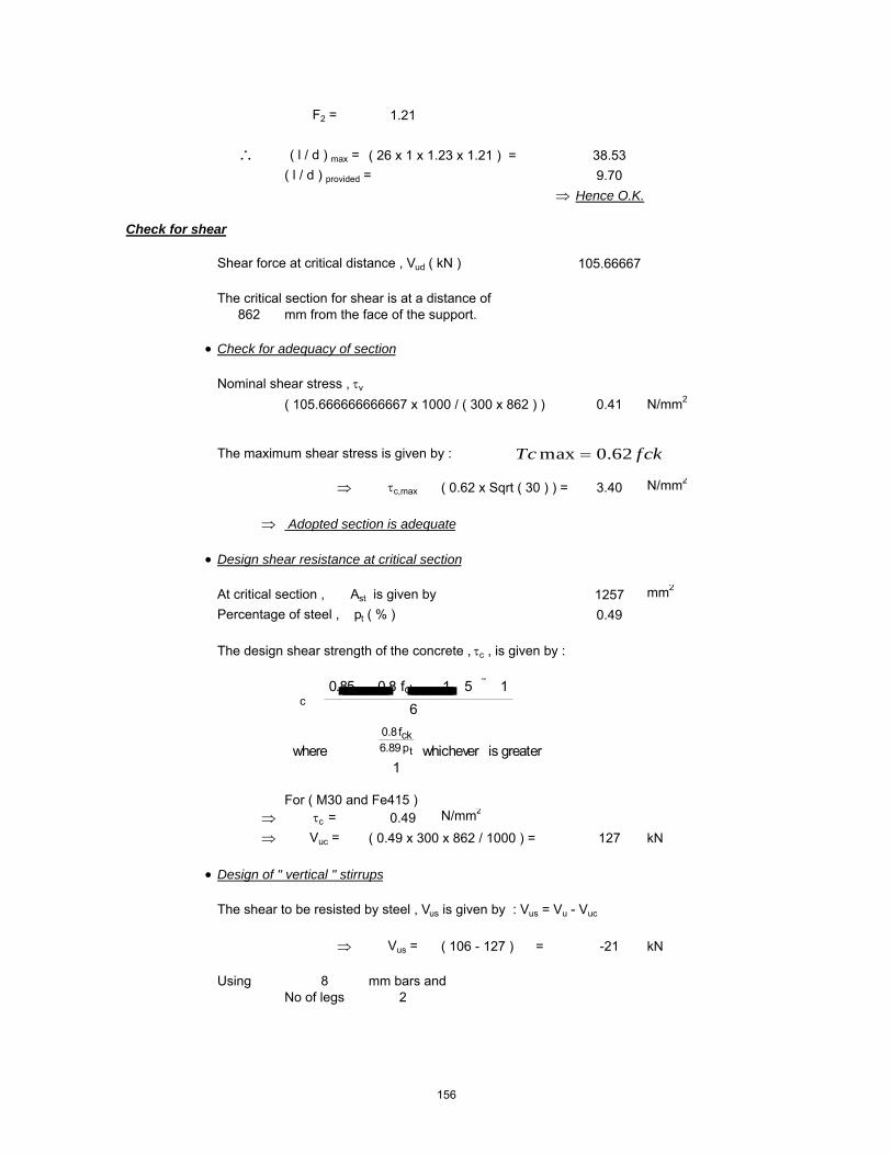
F2 = 1.21
∴ ( l / d ) max = ( 26 x 1 x 1.23 x 1.21 ) = 38.53( l / d ) provided = 9.70
⇒ Hence O.K.
Check for shear
Shear force at critical distance , Vud ( kN ) 105.66667
The critical section for shear is at a distance of 862 mm from the face of the support.
• Check for adequacy of section
Nominal shear stress , τv
( 105.666666666667 x 1000 / ( 300 x 862 ) ) 0.41 N/mm2
The maximum shear stress is given by :
⇒ τc,max ( 0.62 x Sqrt ( 30 ) ) = 3.40 N/mm2
⇒ Adopted section is adequate
• Design shear resistance at critical section
At critical section , Ast is given by 1257 mm2
Percentage of steel , pt ( % ) 0.49
The design shear strength of the concrete , τc , is given by :
For ( M30 and Fe415 ) ⇒ τc = 0.49 N/mm2
⇒ Vuc = ( 0.49 x 300 x 862 / 1000 ) = 127 kN
• Design of " vertical " stirrups
The shear to be resisted by steel , Vus is given by : Vus = Vu - Vuc
⇒ Vus = ( 106 - 127 ) = -21 kN
Using 8 mm bars andNo of legs 2
�c �0.85� �0.8 fck��� 1 5 � 1�
6 �
where � ��0.8fck6.89pt
1whichever is greater
fckTc 62.0max =
156

Area of stirrups , Asv ( mm2 ) 101
⇒ required spacing sv ≤ ( 0.87 x 415 x 101 x 862 / ( -21.27 x 1000 ) )
⇒ Spacing , sv = -1471 mm
Check whether τ v > 0.5 τ c
Nominal shear stress , τv ( N/mm2 ) 0.41Design shear stress , τc ( N/mm2 ) 0.49
τv > 0.5 τc Yes
The Code ( Cl. 26.5.1.6 ) specifies a minimum shear reinforcement to be provided in the form of stirrups in all beams where the calculated nominal shear stress τv
exceeds 0.5 τc. :
The maximum spacing of stirrups should also comply with the requirements mentioned above. For normal " vertical " stirrups, the requirement is
Code requirements for maximum spacing..
i) < ( 2.175 x 415 x 101 / 300 ) = 302 mmii) ≤ ( 0.75 x 862 ) = 647 mmiii) ≤ 300 mm 300 mmiv) ≤ ( 0.87 x 415 x 101 x 862 / ( -21.27 x 1000 ) ) = -1471 mm
sv ��0.75 d300 mm
bfyAsv
tcsvWhenfyb
A
sv
sv
sv
175.2
5.087.0
4.0
=
==
157

Beam B4 Support
Design Parameters
Load Case 15 [1.5*(DL + EQZ)]Grade of Concrete M30Grade of Steel Fe415Characteristic compressive strength of concrete , fck ( N/mm2 ) 30Characteristic yield strength of steel , fy ( N/mm2 ) 415Unit weight of concrete , γc ( kN/m3 ) 24Partial safety factor for concrete 1.5Exposure condition MildNominal Cover to exposure condition( mm ) 20
Dimensions of the beam
C/C Span of the beam , l , ( m ) 1.45Breadth of the beam , b ( mm ) 350Overall depth of the beam , D ( mm ) 900
Details of reinforcements
Diameter of tension reinforcement ( mm ) 25 Diameter of compression reinforcement ( mm ) 25Diameter of stirrups ( mm ) 8
Effective depth
Effective depth , d ( mm ) ( 900-20-8-25/2 ) = 860
Design Moment, Shear Force
The moments and shears given below are taken from the STAAD.Pro 2004 output file.The partial factors of safety are already incorporated into the analysis.
Torsional Moment 20 kN-mBending Moment Mu(kN-m) 706Equivalent Bending Moment , Me ( kNm ) 753Shear force at critical distance , Vud ( kN ) 282Equivalent Shear (kN) 389
Singly reinforced or doubly reinforced section ?
The limiting moment of resistance , Mu,lim is given by
The limiting percentage of steel , pt,lim is given by
SectiontheofdepthEffectivedAxisNeutralofdepthLimitingxu
SectiontheofBreadthbWhere
0.416xu*d
bxu*0.362fckMulim
max
maxmax
==
=
=
158

The area of steel for a singly reinforced section with width , b and depth , d and ultimate moment , Mu is given by :
For ( M30 and Fe415 )
xu,max / d = 0.48
⇒ Mu,lim = ( 0.1389 x 30 x 300 x 859.5^2 / 1000000 ) = 923.50 kNm
⇒ pt,lim = ( 41.3 x 30 / 415 x 0.48 ) = 1.433
If Mu > Mu,lim , the section has to be i) get increased by depth or width ( preferably depth )ii) doubly reinforced
If Mu < Mu,lim , the section can be designed as singly reinforced.
Check for the type of section
Mu = 753.06 kNmMu,lim = 923.50 kNm
⇒ Section can be designed as singly reinforced.
Determining A st
• Considering a ' balanced section ' ( xu = xu,max )Ast = Ast,lim + ΔAst
where Ast,lim = pt,lim / 100 ( b x d )
⇒ Ast,lim ( 1.433 / 100 x 300 x 859.5 ) = 3695 mm2
• Assuming 25 mm bars for compression steel,
d' ≈ ( 20 mm clear cover + 8 mm stirrup + 25 / 2 ) = 40.5 mm
Mu,lim � 0.1389 fck b d2
steelofstrengthticCharcterisfyconcreteofstrengtheCompressivticCharcterisfckWhere
dxu*
fyfck*41.61Pt max
lim
==
=
2
598.42100
bdMuRWhere
fR
fyfckx
bdAstxPt
ck
=
=
159

Mu = 0.87*fy**Ast*d(1-(Ast*fy)/b*d*fck)
Ast Reqd = 2868 mm2
∴ No of tension bars required ( # )( 2868 / ( Pi / 4 x 25^2 ) = 6.00
Actual percentage of steel , pt ( % )( 6 x Pi / 4 x 25 ^2 / 300 / 860 x 100 ) = 1.14
Actual area of steel , Ast ( mm2 )( 6 x Pi / 4 x 25 ^2 ) = 2945
Determining A sc
The compression steel , Asc , is given by
or
where fsc is the stress in compression steel.
The values of fsc ( in MPa units ) at xu = xu,max for variousd' / d ratios and different grades of compression steel are given in the table below.
• Assuming xu = xu,max , for d' / d = ( 40.5 / 859.5 ) = 0.047From the above table : by interpolation
Design Check
• To ensure xu ≤ xu,max , it suffices to establish pc ≥ pc*
�Ast ��Mu Mu,lim�0.87 fy�d d'
�pt100
�R Rlim
0.87 fy�1 d'd
Asc ��0.87 fy���Ast
fsc 0.447 fck
pc �0.87 fy�pt pt,lim
fsc 0.447 fck
Grade of steel d'd
0.05 0.10 0.15 0.20Fe250 217.5 217.5 217.5 217.5Fe415 355.1 351.9 342.4 329.2Fe500 423.9 411.3 395.1 370.3
160

where pc* is given by
Actual pt provided : pt = 1.14Actual pc provided : pc = 0.38
⇒ pc* = ( 0.87 x 415 x ( 1.142 - 1.433 ) / ( 354.98 - 0.447 x 30 ) )
⇒ pc* = -0.31
Section is not over reinforced
Check for deflection control
For prismatic beams of rectangular sections and slabs of uniform thicknesses and spans upto 10m , the limiting l / d ratios are specified by the Code ( Cl. 23.2.1 ) as :
The modification factors F1 ( which varies with pt and fst )and F2 ( which varies with pc ) are as given in Fig .4 and Fig .5 of the code.
Code permits an approximate calculation of fst as follows :
⇒ fst = ( 0.58 x 415 x 3119 / 2945 ) = 254.88 N/mm2
F = 1.00F1 = 0.89
pc �
0.87 fy�fsc 0.447 fck��pt pt,lim
�ld�max
��ld�basic
F1 F2
where �ld�basic
���������7 for cantilever spans20 for simply supported spans
26 for continuous spans
For simply supported and continuous spans over10 m, these ratios are multiplied by a factor F
F �10
span in metres
161

F2 = 0.93
∴ ( l / d ) max = ( 26 x 1 x 0.89 x 0.93 ) = 21.40( l / d ) provided = 1.69
⇒ Hence O.K.
Check for shear
Shear force at critical distance , Vud ( kN ) 388.666667
The critical section for shear is at a distance of 860 mm from the face of the support.
• Check for adequacy of section
Nominal shear stress , τv
( 388.666666666667 x 1000 / ( 300 x 860 ) ) 1.51 N/mm2
The maximum shear stress is given by :
⇒ τc,max ( 0.62 x Sqrt ( 30 ) ) = 3.40 N/mm2
⇒ Adopted section is adequate
• Design shear resistance at critical section
At critical section , Ast is given by 2945 mm2
Percentage of steel , pt ( % ) 1.14
The design shear strength of the concrete , τc , is given by :
For ( M30 and Fe415 ) ⇒ τc = 0.69 N/mm2
⇒ Vuc = ( 0.69 x 300 x 860 / 1000 ) = 178 kN
• Design of " vertical " stirrups
The shear to be resisted by steel , Vus is given by : Vus = Vu - Vuc
⇒ Vus = ( 389 - 178 ) = 211 kN
Using 8 mm bars andNo of legs 2
�c �0.85� �0.8 fck��� 1 5 � 1�
6 �
where � ��0.8fck6.89pt
1whichever is greater
fckTc 62.0max =
162
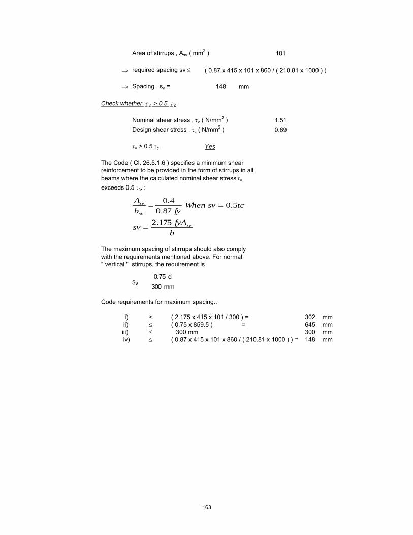
Area of stirrups , Asv ( mm2 ) 101
⇒ required spacing sv ≤ ( 0.87 x 415 x 101 x 860 / ( 210.81 x 1000 ) )
⇒ Spacing , sv = 148 mm
Check whether τ v > 0.5 τ c
Nominal shear stress , τv ( N/mm2 ) 1.51Design shear stress , τc ( N/mm2 ) 0.69
τv > 0.5 τc Yes
The Code ( Cl. 26.5.1.6 ) specifies a minimum shear reinforcement to be provided in the form of stirrups in all beams where the calculated nominal shear stress τv
exceeds 0.5 τc. :
The maximum spacing of stirrups should also comply with the requirements mentioned above. For normal " vertical " stirrups, the requirement is
Code requirements for maximum spacing..
i) < ( 2.175 x 415 x 101 / 300 ) = 302 mmii) ≤ ( 0.75 x 859.5 ) = 645 mmiii) ≤ 300 mm 300 mmiv) ≤ ( 0.87 x 415 x 101 x 860 / ( 210.81 x 1000 ) ) = 148 mm
sv ��0.75 d300 mm
bfyAsv
tcsvWhenfyb
A
sv
sv
sv
175.2
5.087.0
4.0
=
==
163

Beam B4 Mid
Design Parameters
Load Case 15 [1.5*(DL + EQZ)]Grade of Concrete M30Grade of Steel Fe415Characteristic compressive strength of concrete , fck ( N/mm2 ) 30Characteristic yield strength of steel , fy ( N/mm2 ) 415Unit weight of concrete , γc ( kN/m3 ) 24Partial safety factor for concrete 1.5Exposure condition MildNominal Cover to exposure condition( mm ) 20
Dimensions of the beam
C/C Span of the beam , l , ( m ) 1.45Breadth of the beam , b ( mm ) 300Overall depth of the beam , D ( mm ) 900
Details of reinforcements
Diameter of tension reinforcement ( mm ) 20 Diameter of compression reinforcement ( mm ) 20Diameter of stirrups ( mm ) 8
Effective depth
Effective depth , d ( mm ) ( 900-20-8-20/2 ) = 862
Design Moment, Shear Force
The moments and shears given below are taken from the STAAD.Pro 2004 output file.The partial factors of safety are already incorporated into the analysis.
Torsional Moment 20 kN-mBending Moment Mu(kN-m) 314Equivalent Bending Moment , Me ( kNm ) 361Shear force at critical distance , Vud ( kN ) 259Equivalent Shear (kN) 366
Singly reinforced or doubly reinforced section ?
The limiting moment of resistance , Mu,lim is given by
The limiting percentage of steel , pt,lim is given by
SectiontheofdepthEffectivedAxisNeutralofdepthLimitingxu
SectiontheofBreadthbWhere
0.416xu*d
bxu*0.362fckMulim
max
maxmax
==
=
=
164

The area of steel for a singly reinforced section with width , b and depth , d and ultimate moment , Mu is given by :
For ( M30 and Fe415 )
xu,max / d = 0.48
⇒ Mu,lim = ( 0.1389 x 30 x 300 x 862^2 / 1000000 ) = 928.88 kNm
⇒ pt,lim = ( 41.3 x 30 / 415 x 0.48 ) = 1.433
If Mu > Mu,lim , the section has to be i) get increased by depth or width ( preferably depth )ii) doubly reinforced
If Mu < Mu,lim , the section can be designed as singly reinforced.
Check for the type of section
Mu = 361.06 kNmMu,lim = 928.88 kNm
⇒ Section can be designed as singly reinforced.
Determining A st
• Considering a ' balanced section ' ( xu = xu,max )Ast = Ast,lim + ΔAst
where Ast,lim = pt,lim / 100 ( b x d )
⇒ Ast,lim ( 1.433 / 100 x 300 x 862 ) = 3706 mm2
• Assuming 20 mm bars for compression steel,
d' ≈ ( 20 mm clear cover + 8 mm stirrup + 20 / 2 ) = 38 mm
Mu,lim � 0.1389 fck b d2
steelofstrengthticCharcterisfyconcreteofstrengtheCompressivticCharcterisfckWhere
dxu*
fyfck*41.61Pt max
lim
==
=
2
598.42100
bdMuRWhere
fR
fyfckx
bdAstxPt
ck
=
=
165

Mu = 0.87*fy**Ast*d(1-(Ast*fy)/b*d*fck)
Ast Reqd = 1243 mm2
∴ No of tension bars required ( # )( 1243 / ( Pi / 4 x 20^2 ) = 5.00
Actual percentage of steel , pt ( % )( 4 x Pi / 4 x 20 ^2 / 300 / 862 x 100 ) = 0.49
Actual area of steel , Ast ( mm2 )( 4 x Pi / 4 x 20 ^2 ) = 1571
Determining A sc
The compression steel , Asc , is given by
or
where fsc is the stress in compression steel.
The values of fsc ( in MPa units ) at xu = xu,max for variousd' / d ratios and different grades of compression steel are given in the table below.
• Assuming xu = xu,max , for d' / d = ( 38 / 862 ) = 0.044From the above table : by interpolation
Design Check
• To ensure xu ≤ xu,max , it suffices to establish pc ≥ pc*
�Ast ��Mu Mu,lim�0.87 fy�d d'
�pt100
�R Rlim
0.87 fy�1 d'd
Asc ��0.87 fy���Ast
fsc 0.447 fck
pc �0.87 fy�pt pt,lim
fsc 0.447 fck
Grade of steel d'd
0.05 0.10 0.15 0.20Fe250 217.5 217.5 217.5 217.5Fe415 355.1 351.9 342.4 329.2Fe500 423.9 411.3 395.1 370.3
166

where pc* is given by
Actual pt provided : pt = 0.49Actual pc provided : pc = 0.85
⇒ pc* = ( 0.87 x 415 x ( 0.486 - 1.433 ) / ( 354.8 - 0.447 x 30 ) )
⇒ pc* = -1.00
Section is not over reinforced
Check for deflection control
For prismatic beams of rectangular sections and slabs of uniform thicknesses and spans upto 10m , the limiting l / d ratios are specified by the Code ( Cl. 23.2.1 ) as :
The modification factors F1 ( which varies with pt and fst )and F2 ( which varies with pc ) are as given in Fig .4 and Fig .5 of the code.
Code permits an approximate calculation of fst as follows :
⇒ fst = ( 0.58 x 415 x 1797 / 1257 ) = 344.26 N/mm2
F = 1.00F1 = 1.13
pc �
0.87 fy�fsc 0.447 fck��pt pt,lim
�ld�max
��ld�basic
F1 F2
where �ld�basic
���������7 for cantilever spans20 for simply supported spans
26 for continuous spans
For simply supported and continuous spans over10 m, these ratios are multiplied by a factor F
F �10
span in metres
167

F2 = 1.21
∴ ( l / d ) max = ( 26 x 1 x 1.13 x 1.21 ) = 35.62( l / d ) provided = 1.68
⇒ Hence O.K.
Check for shear
Shear force at critical distance , Vud ( kN ) 365.66667
The critical section for shear is at a distance of 862 mm from the face of the support.
• Check for adequacy of section
Nominal shear stress , τv
( 365.666666666667 x 1000 / ( 300 x 862 ) ) 1.41 N/mm2
The maximum shear stress is given by :
⇒ τc,max ( 0.62 x Sqrt ( 30 ) ) = 3.40 N/mm2
⇒ Adopted section is adequate
• Design shear resistance at critical section
At critical section , Ast is given by 1257 mm2
Percentage of steel , pt ( % ) 0.49
The design shear strength of the concrete , τc , is given by :
For ( M30 and Fe415 ) ⇒ τc = 0.49 N/mm2
⇒ Vuc = ( 0.49 x 300 x 862 / 1000 ) = 127 kN
• Design of " vertical " stirrups
The shear to be resisted by steel , Vus is given by : Vus = Vu - Vuc
⇒ Vus = ( 366 - 127 ) = 239 kN
Using 8 mm bars andNo of legs 2
�c �0.85� �0.8 fck��� 1 5 � 1�
6 �
where � ��0.8fck6.89pt
1whichever is greater
fckTc 62.0max =
168

Area of stirrups , Asv ( mm2 ) 101
⇒ required spacing sv ≤ ( 0.87 x 415 x 101 x 862 / ( 238.73 x 1000 ) )
⇒ Spacing , sv = 131 mm
Check whether τ v > 0.5 τ c
Nominal shear stress , τv ( N/mm2 ) 1.41Design shear stress , τc ( N/mm2 ) 0.49
τv > 0.5 τc Yes
The Code ( Cl. 26.5.1.6 ) specifies a minimum shear reinforcement to be provided in the form of stirrups in all beams where the calculated nominal shear stress τv
exceeds 0.5 τc. :
The maximum spacing of stirrups should also comply with the requirements mentioned above. For normal " vertical " stirrups, the requirement is
Code requirements for maximum spacing..
i) < ( 2.175 x 415 x 101 / 300 ) = 302 mmii) ≤ ( 0.75 x 862 ) = 647 mmiii) ≤ 300 mm 300 mmiv) ≤ ( 0.87 x 415 x 101 x 862 / ( 238.73 x 1000 ) ) = 131 mm
sv ��0.75 d300 mm
bfyAsv
tcsvWhenfyb
A
sv
sv
sv
175.2
5.087.0
4.0
=
==
169

Beam B6 Support
Design Parameters
Load Case 14 [1.5*(DL - EQX)]Grade of Concrete M30Grade of Steel Fe415Characteristic compressive strength of concrete , fck ( N/mm2 ) 30Characteristic yield strength of steel , fy ( N/mm2 ) 415Unit weight of concrete , γc ( kN/m3 ) 24Partial safety factor for concrete 1.5Exposure condition MildNominal Cover to exposure condition( mm ) 20
Dimensions of the beam
C/C Span of the beam , l , ( m ) 1.40Breadth of the beam , b ( mm ) 250Overall depth of the beam , D ( mm ) 550
Details of reinforcements
Diameter of tension reinforcement ( mm ) 20 Diameter of compression reinforcement ( mm ) 20Diameter of stirrups ( mm ) 8
Effective depth
Effective depth , d ( mm ) ( 550-20-8-20/2 ) = 512
Design Moment, Shear Force
The moments and shears given below are taken from the STAAD.Pro 2004 output file.The partial factors of safety are already incorporated into the analysis.
Torsional Moment 10 kN-mBending Moment Mu(kN-m) 245Equivalent Bending Moment , Me ( kNm ) 264Shear force at critical distance , Vud ( kN ) 55Equivalent Shear (kN) 119
Singly reinforced or doubly reinforced section ?
The limiting moment of resistance , Mu,lim is given by
The limiting percentage of steel , pt,lim is given by
SectiontheofdepthEffectivedAxisNeutralofdepthLimitingxu
SectiontheofBreadthbWhere
0.416xu*d
bxu*0.362fckMulim
max
maxmax
==
=
=
170

The area of steel for a singly reinforced section with width , b and depth , d and ultimate moment , Mu is given by :
For ( M30 and Fe415 )
xu,max / d = 0.48
⇒ Mu,lim = ( 0.1389 x 30 x 250 x 512^2 / 1000000 ) = 273.09 kNm
⇒ pt,lim = ( 41.3 x 30 / 415 x 0.48 ) = 1.433
If Mu > Mu,lim , the section has to be i) get increased by depth or width ( preferably depth )ii) doubly reinforced
If Mu < Mu,lim , the section can be designed as singly reinforced.
Check for the type of section
Mu = 263.82 kNmMu,lim = 273.09 kNm
⇒ Section can be designed as singly reinforced.
Determining A st
• Considering a ' balanced section ' ( xu = xu,max )Ast = Ast,lim + ΔAst
where Ast,lim = pt,lim / 100 ( b x d )
⇒ Ast,lim ( 1.433 / 100 x 250 x 512 ) = 1834 mm2
• Assuming 20 mm bars for compression steel,
d' ≈ ( 20 mm clear cover + 8 mm stirrup + 20 / 2 ) = 38 mm
Mu,lim � 0.1389 fck b d2
steelofstrengthticCharcterisfyconcreteofstrengtheCompressivticCharcterisfckWhere
dxu*
fyfck*41.61Pt max
lim
==
=
2
598.42100
bdMuRWhere
fR
fyfckx
bdAstxPt
ck
=
=
171

Mu = 0.87*fy**Ast*d(1-(Ast*fy)/b*d*fck)
Ast Reqd = 1763 mm2
∴ No of tension bars required ( # )( 1763 / ( Pi / 4 x 20^2 ) = 6.00
Actual percentage of steel , pt ( % )( 6 x Pi / 4 x 20 ^2 / 250 / 512 x 100 ) = 1.47
Actual area of steel , Ast ( mm2 )( 6 x Pi / 4 x 20 ^2 ) = 1885
Determining A sc
The compression steel , Asc , is given by
or
where fsc is the stress in compression steel.
The values of fsc ( in MPa units ) at xu = xu,max for variousd' / d ratios and different grades of compression steel are given in the table below.
• Assuming xu = xu,max , for d' / d = ( 38 / 512 ) = 0.074From the above table : by interpolation
Design Check
• To ensure xu ≤ xu,max , it suffices to establish pc ≥ pc*
�Ast ��Mu Mu,lim�0.87 fy�d d'
�pt100
�R Rlim
0.87 fy�1 d'd
Asc ��0.87 fy���Ast
fsc 0.447 fck
pc �0.87 fy�pt pt,lim
fsc 0.447 fck
Grade of steel d'd
0.05 0.10 0.15 0.20Fe250 217.5 217.5 217.5 217.5Fe415 355.1 351.9 342.4 329.2Fe500 423.9 411.3 395.1 370.3
172

where pc* is given by
Actual pt provided : pt = 1.47Actual pc provided : pc = 0.25
⇒ pc* = ( 0.87 x 415 x ( 1.473 - 1.433 ) / ( 354.61 - 0.447 x 30 ) )
⇒ pc* = 0.04
Section is not over reinforced
Check for deflection control
For prismatic beams of rectangular sections and slabs of uniform thicknesses and spans upto 10m , the limiting l / d ratios are specified by the Code ( Cl. 23.2.1 ) as :
The modification factors F1 ( which varies with pt and fst )and F2 ( which varies with pc ) are as given in Fig .4 and Fig .5 of the code.
Code permits an approximate calculation of fst as follows :
⇒ fst = ( 0.58 x 415 x 1780 / 1885 ) = 227.32 N/mm2
F = 1.00F1 = 0.83
pc �
0.87 fy�fsc 0.447 fck��pt pt,lim
�ld�max
��ld�basic
F1 F2
where �ld�basic
���������7 for cantilever spans20 for simply supported spans
26 for continuous spans
For simply supported and continuous spans over10 m, these ratios are multiplied by a factor F
F �10
span in metres
173

F2 = 0.75
∴ ( l / d ) max = ( 26 x 1 x 0.83 x 0.75 ) = 16.36( l / d ) provided = 2.73
⇒ Hence O.K.
Check for shear
Shear force at critical distance , Vud ( kN ) 119
The critical section for shear is at a distance of 512 mm from the face of the support.
• Check for adequacy of section
Nominal shear stress , τv
( 119 x 1000 / ( 250 x 512 ) ) = 0.93 N/mm2
The maximum shear stress is given by :
⇒ τc,max ( 0.62 x Sqrt ( 30 ) ) 3.40 N/mm2
⇒ Adopted section is adequate
• Design shear resistance at critical section
At critical section , Ast is given by 1885 mm2
Percentage of steel , pt ( % ) 1.47
The design shear strength of the concrete , τc , is given by :
For ( M30 and Fe415 ) ⇒ τc = 0.76 N/mm2
⇒ Vuc = ( 0.76 x 250 x 512 / 1000 ) = 97 kN
• Design of " vertical " stirrups
The shear to be resisted by steel , Vus is given by : Vus = Vu - Vuc
⇒ Vus = ( 119 - 97 ) = 22 kN
Using 8 mm bars andNo of legs 2
�c �0.85� �0.8 fck��� 1 5 � 1�
6 �
where � ��0.8fck6.89pt
1whichever is greater
fckTc 62.0max =
174

Area of stirrups , Asv ( mm2 ) 101
⇒ required spacing sv ≤ ( 0.87 x 415 x 101 x 512 / ( 22.05 x 1000 ) )
⇒ Spacing , sv = 843 mm
Check whether τ v > 0.5 τ c
Nominal shear stress , τv ( N/mm2 ) 0.93Design shear stress , τc ( N/mm2 ) 0.76
τv > 0.5 τc Yes
The Code ( Cl. 26.5.1.6 ) specifies a minimum shear reinforcement to be provided in the form of stirrups in all beams where the calculated nominal shear stress τv
exceeds 0.5 τc. :
The maximum spacing of stirrups should also comply with the requirements mentioned above. For normal " vertical " stirrups, the requirement is
Code requirements for maximum spacing..
i) < ( 2.175 x 415 x 101 / 250 ) = 363 mmii) ≤ ( 0.75 x 512 ) = 384 mmiii) ≤ 300 mm 300 mmiv) ≤ ( 0.87 x 415 x 101 x 512 / ( 22.05 x 1000 ) ) = 843 mm
sv ��0.75 d300 mm
bfyAsv
tcsvWhenfyb
A
sv
sv
sv
175.2
5.087.0
4.0
=
==
175

Beam B6 Mid
Design Parameters
Load Case 14 [1.5*(DL - EQX)]Grade of Concrete M30Grade of Steel Fe415Characteristic compressive strength of concrete , fck ( N/mm2 ) 30Characteristic yield strength of steel , fy ( N/mm2 ) 415Unit weight of concrete , γc ( kN/m3 ) 24Partial safety factor for concrete 1.5Exposure condition MildNominal Cover to exposure condition( mm ) 20
Dimensions of the beam
C/C Span of the beam , l , ( m ) 1.40Breadth of the beam , b ( mm ) 250Overall depth of the beam , D ( mm ) 550
Details of reinforcements
Diameter of tension reinforcement ( mm ) 20 Diameter of compression reinforcement ( mm ) 20Diameter of stirrups ( mm ) 8
Effective depth
Effective depth , d ( mm ) ( 550-20-8-20/2 ) = 512
Design Moment, Shear Force
The moments and shears given below are taken from the STAAD.Pro 2004 output file.The partial factors of safety are already incorporated into the analysis.
Torsional Moment 10 kN-mBending Moment Mu(kN-m) 118Equivalent Bending Moment , Me ( kNm ) 137Shear force at critical distance , Vud ( kN ) 55Equivalent Shear (kN) 119
Singly reinforced or doubly reinforced section ?
The limiting moment of resistance , Mu,lim is given by
The limiting percentage of steel , pt,lim is given by
SectiontheofdepthEffectivedAxisNeutralofdepthLimitingxu
SectiontheofBreadthbWhere
0.416xu*d
bxu*0.362fckMulim
max
maxmax
==
=
=
176

The area of steel for a singly reinforced section with width , b and depth , d and ultimate moment , Mu is given by :
For ( M30 and Fe415 )
xu,max / d = 0.48
⇒ Mu,lim = ( 0.1389 x 30 x 250 x 512^2 / 1000000 ) = 273.09 kNm
⇒ pt,lim = ( 41.3 x 30 / 415 x 0.48 ) = 1.433
If Mu > Mu,lim , the section has to be i) get increased by depth or width ( preferably depth )ii) doubly reinforced
If Mu < Mu,lim , the section can be designed as singly reinforced.
Check for the type of section
Mu = 136.82 kNmMu,lim = 273.09 kNm
⇒ Section can be designed as singly reinforced.
Determining A st
• Considering a ' balanced section ' ( xu = xu,max )Ast = Ast,lim + ΔAst
where Ast,lim = pt,lim / 100 ( b x d )
⇒ Ast,lim ( 1.433 / 100 x 250 x 512 ) = 1834 mm2
• Assuming 20 mm bars for compression steel,
d' ≈ ( 20 mm clear cover + 8 mm stirrup + 20 / 2 ) = 38 mm
Mu,lim � 0.1389 fck b d2
steelofstrengthticCharcterisfyconcreteofstrengtheCompressivticCharcterisfckWhere
dxu*
fyfck*41.61Pt max
lim
==
=
2
598.42100
bdMuRWhere
fR
fyfckx
bdAstxPt
ck
=
=
177

Mu = 0.87*fy**Ast*d(1-(Ast*fy)/b*d*fck)
Ast Reqd = 811 mm2
∴ No of tension bars required ( # )( 811 / ( Pi / 4 x 20^2 ) = 3.00
Actual percentage of steel , pt ( % )( 3 x Pi / 4 x 20 ^2 / 250 / 512 x 100 ) = 0.74
Actual area of steel , Ast ( mm2 )( 3 x Pi / 4 x 20 ^2 ) = 942
Determining A sc
The compression steel , Asc , is given by
or
where fsc is the stress in compression steel.
The values of fsc ( in MPa units ) at xu = xu,max for variousd' / d ratios and different grades of compression steel are given in the table below.
• Assuming xu = xu,max , for d' / d = ( 38 / 512 ) = 0.074From the above table : by interpolation
Design Check
• To ensure xu ≤ xu,max , it suffices to establish pc ≥ pc*
�Ast ��Mu Mu,lim�0.87 fy�d d'
�pt100
�R Rlim
0.87 fy�1 d'd
Asc ��0.87 fy���Ast
fsc 0.447 fck
pc �0.87 fy�pt pt,lim
fsc 0.447 fck
Grade of steel d'd
0.05 0.10 0.15 0.20Fe250 217.5 217.5 217.5 217.5Fe415 355.1 351.9 342.4 329.2Fe500 423.9 411.3 395.1 370.3
178

where pc* is given by
Actual pt provided : pt = 0.74Actual pc provided : pc = 0.74
⇒ pc* = ( 0.87 x 415 x ( 0.736 - 1.433 ) / ( 354.61 - 0.447 x 30 ) )
⇒ pc* = -0.74
Section is not over reinforced
Check for deflection control
For prismatic beams of rectangular sections and slabs of uniform thicknesses and spans upto 10m , the limiting l / d ratios are specified by the Code ( Cl. 23.2.1 ) as :
The modification factors F1 ( which varies with pt and fst )and F2 ( which varies with pc ) are as given in Fig .4 and Fig .5 of the code.
Code permits an approximate calculation of fst as follows :
⇒ fst = ( 0.58 x 415 x 1038 / 942 ) = 265.12 N/mm2
F = 1.00F1 = 1.13
pc �
0.87 fy�fsc 0.447 fck��pt pt,lim
�ld�max
��ld�basic
F1 F2
where �ld�basic
���������7 for cantilever spans20 for simply supported spans
26 for continuous spans
For simply supported and continuous spans over10 m, these ratios are multiplied by a factor F
F �10
span in metres
179

F2 = 1.16
∴ ( l / d ) max = ( 26 x 1 x 1.13 x 1.16 ) = 34.13( l / d ) provided = 2.73
⇒ Hence O.K.
Check for shear
Shear force at critical distance , Vud ( kN ) 119
The critical section for shear is at a distance of 512 mm from the face of the support.
• Check for adequacy of section
Nominal shear stress , τv
( 119 x 1000 / ( 250 x 512 ) ) = 0.93 N/mm2
The maximum shear stress is given by :
⇒ τc,max ( 0.62 x Sqrt ( 30 ) ) = 3.40 N/mm2
⇒ Adopted section is adequate
• Design shear resistance at critical section
At critical section , Ast is given by 942 mm2
Percentage of steel , pt ( % ) 0.74
The design shear strength of the concrete , τc , is given by :
For ( M30 and Fe415 ) ⇒ τc = 0.58 N/mm2
⇒ Vuc = ( 0.58 x 250 x 512 / 1000 ) = 74 kN
• Design of " vertical " stirrups
The shear to be resisted by steel , Vus is given by : Vus = Vu - Vuc
⇒ Vus = ( 119 - 74 ) = 45 kN
Using 8 mm bars andNo of legs 2
�c �0.85� �0.8 fck��� 1 5 � 1�
6 �
where � ��0.8fck6.89pt
1whichever is greater
fckTc 62.0max =
180

Area of stirrups , Asv ( mm2 ) 101
⇒ required spacing sv ≤ ( 0.87 x 415 x 101 x 512 / ( 44.54 x 1000 ) )
⇒ Spacing , sv = 417 mm
Check whether τ v > 0.5 τ c
Nominal shear stress , τv ( N/mm2 ) 0.93Design shear stress , τc ( N/mm2 ) 0.58
τv > 0.5 τc Yes
The Code ( Cl. 26.5.1.6 ) specifies a minimum shear reinforcement to be provided in the form of stirrups in all beams where the calculated nominal shear stress τv
exceeds 0.5 τc. :
The maximum spacing of stirrups should also comply with the requirements mentioned above. For normal " vertical " stirrups, the requirement is
Code requirements for maximum spacing..
i) < ( 2.175 x 415 x 101 / 250 ) = 363 mmii) ≤ ( 0.75 x 512 ) = 384 mmiii) ≤ 300 mm 300 mmiv) ≤ ( 0.87 x 415 x 101 x 512 / ( 44.54 x 1000 ) ) = 417 mm
sv ��0.75 d300 mm
bfyAsv
tcsvWhenfyb
A
sv
sv
sv
175.2
5.087.0
4.0
=
==
181

Beam RB1 Support
Design Parameters
Load Case 14 [1.5*(DL - EQX)]Grade of Concrete M30Grade of Steel Fe415Characteristic compressive strength of concrete , fck ( N/mm2 ) 30Characteristic yield strength of steel , fy ( N/mm2 ) 415Unit weight of concrete , γc ( kN/m3 ) 24Partial safety factor for concrete 1.5Exposure condition MildNominal Cover to exposure condition( mm ) 20
Dimensions of the beam
C/C Span of the beam , l , ( m ) 5.35Breadth of the beam , b ( mm ) 300Overall depth of the beam , D ( mm ) 500
Details of reinforcements
Diameter of tension reinforcement ( mm ) 25 Diameter of compression reinforcement ( mm ) 25Diameter of stirrups ( mm ) 8
Effective depth
Effective depth , d ( mm ) ( 500-20-8-25/2 ) = 460
Design Moment, Shear Force
The moments and shears given below are taken from the STAAD.Pro 2004 output file.The partial factors of safety are already incorporated into the analysis.
Torsional Moment 0 kN-mBending Moment Mu(kN-m) 235Equivalent Bending Moment , Me ( kNm ) 235Shear force at critical distance , Vud ( kN ) 125Equivalent Shear (kN) 125
Singly reinforced or doubly reinforced section ?
The limiting moment of resistance , Mu,lim is given by
The limiting percentage of steel , pt,lim is given by
SectiontheofdepthEffectivedAxisNeutralofdepthLimitingxu
SectiontheofBreadthbWhere
0.416xu*d
bxu*0.362fckMulim
max
maxmax
==
=
=
182

The area of steel for a singly reinforced section with width , b and depth , d and ultimate moment , Mu is given by :
For ( M30 and Fe415 )
xu,max / d = 0.48
⇒ Mu,lim = ( 0.1389 x 30 x 300 x 459.5^2 / 1000000 ) = 263.95 kNm
⇒ pt,lim = ( 41.3 x 30 / 415 x 0.48 ) = 1.433
If Mu > Mu,lim , the section has to be i) get increased by depth or width ( preferably depth )ii) doubly reinforced
If Mu < Mu,lim , the section can be designed as singly reinforced.
Check for the type of section
Mu = 235.00 kNmMu,lim = 263.95 kNm
⇒ Section can be designed as singly reinforced.
Determining A st
• Considering a ' balanced section ' ( xu = xu,max )Ast = Ast,lim + ΔAst
where Ast,lim = pt,lim / 100 ( b x d )
⇒ Ast,lim ( 1.433 / 100 x 300 x 459.5 ) = 1975 mm2
• Assuming 25 mm bars for compression steel,
d' ≈ ( 20 mm clear cover + 8 mm stirrup + 25 / 2 ) = 40.5 mm
Mu,lim � 0.1389 fck b d2
steelofstrengthticCharcterisfyconcreteofstrengtheCompressivticCharcterisfckWhere
dxu*
fyfck*41.61Pt max
lim
==
=
2
598.42100
bdMuRWhere
fR
fyfckx
bdAstxPt
ck
=
=
183

Mu = 0.87*fy**Ast*d(1-(Ast*fy)/b*d*fck)
Ast Reqd = 1710 mm2
∴ No of tension bars required ( # )( 1710 / ( Pi / 4 x 25^2 ) = 4.00
Actual percentage of steel , pt ( % )( 4 x Pi / 4 x 25 ^2 / 300 / 460 x 100 ) = 1.42
Actual area of steel , Ast ( mm2 )( 4 x Pi / 4 x 25 ^2 ) = 1963
Determining A sc
The compression steel , Asc , is given by
or
where fsc is the stress in compression steel.
The values of fsc ( in MPa units ) at xu = xu,max for variousd' / d ratios and different grades of compression steel are given in the table below.
• Assuming xu = xu,max , for d' / d = ( 40.5 / 459.5 ) = 0.088From the above table : by interpolation
Design Check
• To ensure xu ≤ xu,max , it suffices to establish pc ≥ pc*
�Ast ��Mu Mu,lim�0.87 fy�d d'
�pt100
�R Rlim
0.87 fy�1 d'd
Asc ��0.87 fy���Ast
fsc 0.447 fck
pc �0.87 fy�pt pt,lim
fsc 0.447 fck
Grade of steel d'd
0.05 0.10 0.15 0.20Fe250 217.5 217.5 217.5 217.5Fe415 355.1 351.9 342.4 329.2Fe500 423.9 411.3 395.1 370.3
184

where pc* is given by
Actual pt provided : pt = 1.42Actual pc provided : pc = 0.36
⇒ pc* = ( 0.87 x 415 x ( 1.424 - 1.433 ) / ( 353.38 - 0.447 x 30 ) )
⇒ pc* = -0.01
Section is not over reinforced
Check for deflection control
For prismatic beams of rectangular sections and slabs of uniform thicknesses and spans upto 10m , the limiting l / d ratios are specified by the Code ( Cl. 23.2.1 ) as :
The modification factors F1 ( which varies with pt and fst )and F2 ( which varies with pc ) are as given in Fig .4 and Fig .5 of the code.
Code permits an approximate calculation of fst as follows :
⇒ fst = ( 0.58 x 415 x 1784 / 1963 ) = 218.71 N/mm2
F = 1.00F1 = 0.87
pc �
0.87 fy�fsc 0.447 fck��pt pt,lim
�ld�max
��ld�basic
F1 F2
where �ld�basic
���������7 for cantilever spans20 for simply supported spans
26 for continuous spans
For simply supported and continuous spans over10 m, these ratios are multiplied by a factor F
F �10
span in metres
185

F2 = 0.90
∴ ( l / d ) max = ( 26 x 1 x 0.87 x 0.9 ) = 20.41( l / d ) provided = 11.63
⇒ Hence O.K.
Check for shear
Shear force at critical distance , Vud ( kN ) 125
The critical section for shear is at a distance of 460 mm from the face of the support.
• Check for adequacy of section
Nominal shear stress , τv
( 125 x 1000 / ( 300 x 460 ) ) = 0.91 N/mm2
The maximum shear stress is given by :
⇒ τc,max ( 0.62 x Sqrt ( 30 ) ) = 3.40 N/mm2
⇒ Adopted section is adequate
• Design shear resistance at critical section
At critical section , Ast is given by 1963 mm2
Percentage of steel , pt ( % ) 1.42
The design shear strength of the concrete , τc , is given by :
For ( M30 and Fe415 ) ⇒ τc = 0.75 N/mm2
⇒ Vuc = ( 0.75 x 300 x 460 / 1000 ) = 103 kN
• Design of " vertical " stirrups
The shear to be resisted by steel , Vus is given by : Vus = Vu - Vuc
⇒ Vus = ( 125 - 103 ) = 22 kN
Using 12 mm bars andNo of legs 2
�c �0.85� �0.8 fck��� 1 5 � 1�
6 �
where � ��0.8fck6.89pt
1whichever is greater
fckTc 62.0max =
186

Area of stirrups , Asv ( mm2 ) 226
⇒ required spacing sv ≤ ( 0.87 x 415 x 226 x 460 / ( 21.84 x 1000 ) )
⇒ Spacing , sv = 1718 mm
Check whether τ v > 0.5 τ c
Nominal shear stress , τv ( N/mm2 ) 0.91Design shear stress , τc ( N/mm2 ) 0.75
τv > 0.5 τc Yes
The Code ( Cl. 26.5.1.6 ) specifies a minimum shear reinforcement to be provided in the form of stirrups in all beams where the calculated nominal shear stress τv
exceeds 0.5 τc. :
The maximum spacing of stirrups should also comply with the requirements mentioned above. For normal " vertical " stirrups, the requirement is
Code requirements for maximum spacing..
i) < ( 2.175 x 415 x 226 / 300 ) = 681 mmii) ≤ ( 0.75 x 459.5 ) = 345 mmiii) ≤ 300 mm 300 mmiv) ≤ ( 0.87 x 415 x 226 x 460 / ( 21.84 x 1000 ) ) = 1718 mm
sv ��0.75 d300 mm
bfyAsv
tcsvWhenfyb
A
sv
sv
sv
175.2
5.087.0
4.0
=
==
187

Beam RB1 Mid
Design Parameters
Load Case 14 [1.5*(DL - EQX)]Grade of Concrete M30Grade of Steel Fe415Characteristic compressive strength of concrete , fck ( N/mm2 ) 30Characteristic yield strength of steel , fy ( N/mm2 ) 415Unit weight of concrete , γc ( kN/m3 ) 24Partial safety factor for concrete 1.5Exposure condition MildNominal Cover to exposure condition( mm ) 20
Dimensions of the beam
C/C Span of the beam , l , ( m ) 5.35Breadth of the beam , b ( mm ) 300Overall depth of the beam , D ( mm ) 500
Details of reinforcements
Diameter of tension reinforcement ( mm ) 25 Diameter of compression reinforcement ( mm ) 25Diameter of stirrups ( mm ) 8
Effective depth
Effective depth , d ( mm ) ( 500-20-8-25/2 ) = 460
Design Moment, Shear Force
The moments and shears given below are taken from the STAAD.Pro 2004 output file.The partial factors of safety are already incorporated into the analysis.
Torsional Moment 0 kN-mBending Moment Mu(kN-m) 150Equivalent Bending Moment , Me ( kNm ) 150Shear force at critical distance , Vud ( kN ) 120Equivalent Shear (kN) 120
Singly reinforced or doubly reinforced section ?
The limiting moment of resistance , Mu,lim is given by
The limiting percentage of steel , pt,lim is given by
SectiontheofdepthEffectivedAxisNeutralofdepthLimitingxu
SectiontheofBreadthbWhere
0.416xu*d
bxu*0.362fckMulim
max
maxmax
==
=
=
188

The area of steel for a singly reinforced section with width , b and depth , d and ultimate moment , Mu is given by :
For ( M30 and Fe415 )
xu,max / d = 0.48
⇒ Mu,lim = ( 0.1389 x 30 x 300 x 459.5^2 / 1000000 ) = 263.95 kNm
⇒ pt,lim = ( 41.3 x 30 / 415 x 0.48 ) = 1.433
If Mu > Mu,lim , the section has to be i) get increased by depth or width ( preferably depth )ii) doubly reinforced
If Mu < Mu,lim , the section can be designed as singly reinforced.
Check for the type of section
Mu = 150.00 kNmMu,lim = 263.95 kNm
⇒ Section can be designed as singly reinforced.
Determining A st
• Considering a ' balanced section ' ( xu = xu,max )Ast = Ast,lim + ΔAst
where Ast,lim = pt,lim / 100 ( b x d )
⇒ Ast,lim ( 1.433 / 100 x 300 x 459.5 ) = 1975 mm2
• Assuming 25 mm bars for compression steel,
d' ≈ ( 20 mm clear cover + 8 mm stirrup + 25 / 2 ) = 40.5 mm
Mu,lim � 0.1389 fck b d2
steelofstrengthticCharcterisfyconcreteofstrengtheCompressivticCharcterisfckWhere
dxu*
fyfck*41.61Pt max
lim
==
=
2
598.42100
bdMuRWhere
fR
fyfckx
bdAstxPt
ck
=
=
189
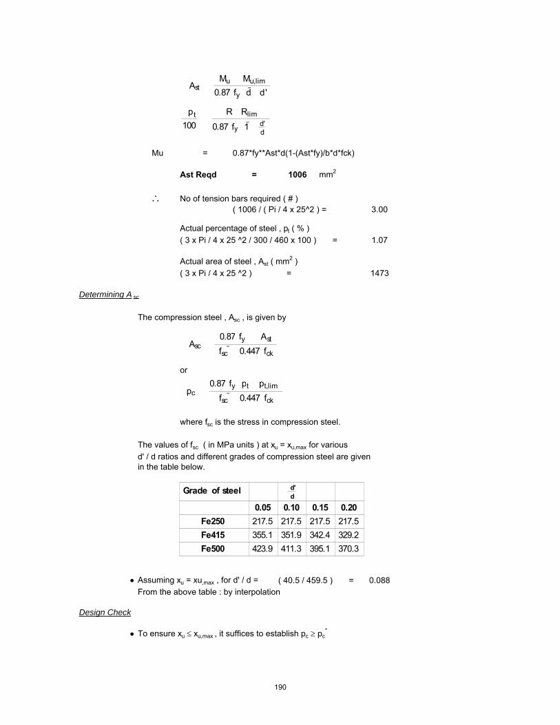
Mu = 0.87*fy**Ast*d(1-(Ast*fy)/b*d*fck)
Ast Reqd = 1006 mm2
∴ No of tension bars required ( # )( 1006 / ( Pi / 4 x 25^2 ) = 3.00
Actual percentage of steel , pt ( % )( 3 x Pi / 4 x 25 ^2 / 300 / 460 x 100 ) = 1.07
Actual area of steel , Ast ( mm2 )( 3 x Pi / 4 x 25 ^2 ) = 1473
Determining A sc
The compression steel , Asc , is given by
or
where fsc is the stress in compression steel.
The values of fsc ( in MPa units ) at xu = xu,max for variousd' / d ratios and different grades of compression steel are given in the table below.
• Assuming xu = xu,max , for d' / d = ( 40.5 / 459.5 ) = 0.088From the above table : by interpolation
Design Check
• To ensure xu ≤ xu,max , it suffices to establish pc ≥ pc*
�Ast ��Mu Mu,lim�0.87 fy�d d'
�pt100
�R Rlim
0.87 fy�1 d'd
Asc ��0.87 fy���Ast
fsc 0.447 fck
pc �0.87 fy�pt pt,lim
fsc 0.447 fck
Grade of steel d'd
0.05 0.10 0.15 0.20Fe250 217.5 217.5 217.5 217.5Fe415 355.1 351.9 342.4 329.2Fe500 423.9 411.3 395.1 370.3
190

where pc* is given by
Actual pt provided : pt = 1.07Actual pc provided : pc = 0.71
⇒ pc* = ( 0.87 x 415 x ( 1.068 - 1.433 ) / ( 353.38 - 0.447 x 30 ) )
⇒ pc* = -0.39
Section is not over reinforced
Check for deflection control
For prismatic beams of rectangular sections and slabs of uniform thicknesses and spans upto 10m , the limiting l / d ratios are specified by the Code ( Cl. 23.2.1 ) as :
The modification factors F1 ( which varies with pt and fst )and F2 ( which varies with pc ) are as given in Fig .4 and Fig .5 of the code.
Code permits an approximate calculation of fst as follows :
⇒ fst = ( 0.58 x 415 x 1222 / 1473 ) = 199.78 N/mm2
F = 1.00F1 = 1.10
pc �
0.87 fy�fsc 0.447 fck��pt pt,lim
�ld�max
��ld�basic
F1 F2
where �ld�basic
���������7 for cantilever spans20 for simply supported spans
26 for continuous spans
For simply supported and continuous spans over10 m, these ratios are multiplied by a factor F
F �10
span in metres
191

F2 = 1.15
∴ ( l / d ) max = ( 26 x 1 x 1.1 x 1.15 ) = 33.00( l / d ) provided = 11.63
⇒ Hence O.K.
Check for shear
Shear force at critical distance , Vud ( kN ) 120
The critical section for shear is at a distance of 460 mm from the face of the support.
• Check for adequacy of section
Nominal shear stress , τv
( 120 x 1000 / ( 300 x 460 ) ) = 0.87 N/mm2
The maximum shear stress is given by :
⇒ τc,max ( 0.62 x Sqrt ( 30 ) ) = 3.40 N/mm2
⇒ Adopted section is adequate
• Design shear resistance at critical section
At critical section , Ast is given by 1473 mm2
Percentage of steel , pt ( % ) 1.07
The design shear strength of the concrete , τc , is given by :
For ( M30 and Fe415 ) ⇒ τc = 0.67 N/mm2
⇒ Vuc = ( 0.67 x 300 x 460 / 1000 ) = 93 kN
• Design of " vertical " stirrups
The shear to be resisted by steel , Vus is given by : Vus = Vu - Vuc
⇒ Vus = ( 120 - 93 ) = 27 kN
Using 12 mm bars andNo of legs 4
�c �0.85� �0.8 fck��� 1 5 � 1�
6 �
where � ��0.8fck6.89pt
1whichever is greater
fckTc 62.0max =
192

Area of stirrups , Asv ( mm2 ) 452
⇒ required spacing sv ≤ ( 0.87 x 415 x 452 x 460 / ( 27.29 x 1000 ) )
⇒ Spacing , sv = 2750 mm
Check whether τ v > 0.5 τ c
Nominal shear stress , τv ( N/mm2 ) 0.87Design shear stress , τc ( N/mm2 ) 0.67
τv > 0.5 τc Yes
The Code ( Cl. 26.5.1.6 ) specifies a minimum shear reinforcement to be provided in the form of stirrups in all beams where the calculated nominal shear stress τv
exceeds 0.5 τc. :
The maximum spacing of stirrups should also comply with the requirements mentioned above. For normal " vertical " stirrups, the requirement is
Code requirements for maximum spacing..
i) < ( 2.175 x 415 x 452 / 300 ) = 1361 mmii) ≤ ( 0.75 x 459.5 ) = 345 mmiii) ≤ 300 mm 300 mmiv) ≤ ( 0.87 x 415 x 452 x 460 / ( 27.29 x 1000 ) ) = 2750 mm
sv ��0.75 d300 mm
bfyAsv
tcsvWhenfyb
A
sv
sv
sv
175.2
5.087.0
4.0
=
==
193

Beam RB2 Support
Design Parameters
Load Case 14 [1.5*(DL - EQX)]Grade of Concrete M30Grade of Steel Fe415Characteristic compressive strength of concrete , fck ( N/mm2 ) 30Characteristic yield strength of steel , fy ( N/mm2 ) 415Unit weight of concrete , γc ( kN/m3 ) 24Partial safety factor for concrete 1.5Exposure condition MildNominal Cover to exposure condition( mm ) 20
Dimensions of the beam
C/C Span of the beam , l , ( m ) 5.36Breadth of the beam , b ( mm ) 300Overall depth of the beam , D ( mm ) 400
Details of reinforcements
Diameter of tension reinforcement ( mm ) 25 Diameter of compression reinforcement ( mm ) 25Diameter of stirrups ( mm ) 8
Effective depth
Effective depth , d ( mm ) ( 650-20-8-25/2 ) = 610
Design Moment, Shear Force
The moments and shears given below are taken from the STAAD.Pro 2004 output file.The partial factors of safety are already incorporated into the analysis.
Torsional Moment 16 kN-mBending Moment Mu(kN-m) 325Equivalent Bending Moment , Me ( kNm ) 355Shear force at critical distance , Vud ( kN ) 70Equivalent Shear (kN) 155
Singly reinforced or doubly reinforced section ?
The limiting moment of resistance , Mu,lim is given by
The limiting percentage of steel , pt,lim is given by
SectiontheofdepthEffectivedAxisNeutralofdepthLimitingxu
SectiontheofBreadthbWhere
0.416xu*d
bxu*0.362fckMulim
max
maxmax
==
=
=
194

The area of steel for a singly reinforced section with width , b and depth , d and ultimate moment , Mu is given by :
For ( M30 and Fe415 )
xu,max / d = 0.48
⇒ Mu,lim = ( 0.1389 x 30 x 300 x 609.5^2 / 1000000 ) = 464.40 kNm
⇒ pt,lim = ( 41.3 x 30 / 415 x 0.48 ) = 1.433
If Mu > Mu,lim , the section has to be i) get increased by depth or width ( preferably depth )ii) doubly reinforced
If Mu < Mu,lim , the section can be designed as singly reinforced.
Check for the type of section
Mu = 354.80 kNmMu,lim = 464.40 kNm
⇒ Section can be designed as singly reinforced.
Determining A st
• Considering a ' balanced section ' ( xu = xu,max )Ast = Ast,lim + ΔAst
where Ast,lim = pt,lim / 100 ( b x d )
⇒ Ast,lim ( 1.433 / 100 x 300 x 609.5 ) = 2620 mm2
• Assuming 25 mm bars for compression steel,
d' ≈ ( 20 mm clear cover + 8 mm stirrup + 25 / 2 ) = 40.5 mm
Mu,lim � 0.1389 fck b d2
steelofstrengthticCharcterisfyconcreteofstrengtheCompressivticCharcterisfckWhere
dxu*
fyfck*41.61Pt max
lim
==
=
2
598.42100
bdMuRWhere
fR
fyfckx
bdAstxPt
ck
=
=
195

Mu = 0.87*fy**Ast*d(1-(Ast*fy)/b*d*fck)
Ast Reqd = 1880 mm2
∴ No of tension bars required ( # )( 1880 / ( Pi / 4 x 25^2 ) = 4.00
Actual percentage of steel , pt ( % )( 4 x Pi / 4 x 25 ^2 / 300 / 610 x 100 ) = 1.07
Actual area of steel , Ast ( mm2 )( 4 x Pi / 4 x 25 ^2 ) = 1963
Determining A sc
The compression steel , Asc , is given by
or
where fsc is the stress in compression steel.
The values of fsc ( in MPa units ) at xu = xu,max for variousd' / d ratios and different grades of compression steel are given in the table below.
• Assuming xu = xu,max , for d' / d = ( 40.5 / 609.5 ) = 0.066From the above table : by interpolation
Design Check
• To ensure xu ≤ xu,max , it suffices to establish pc ≥ pc*
�Ast ��Mu Mu,lim�0.87 fy�d d'
�pt100
�R Rlim
0.87 fy�1 d'd
Asc ��0.87 fy���Ast
fsc 0.447 fck
pc �0.87 fy�pt pt,lim
fsc 0.447 fck
Grade of steel d'd
0.05 0.10 0.15 0.20Fe250 217.5 217.5 217.5 217.5Fe415 355.1 351.9 342.4 329.2Fe500 423.9 411.3 395.1 370.3
196

where pc* is given by
Actual pt provided : pt = 1.07Actual pc provided : pc = 0.54
⇒ pc* = ( 0.87 x 415 x ( 1.074 - 1.433 ) / ( 355.03 - 0.447 x 30 ) )
⇒ pc* = -0.38
Section is not over reinforced
Check for deflection control
For prismatic beams of rectangular sections and slabs of uniform thicknesses and spans upto 10m , the limiting l / d ratios are specified by the Code ( Cl. 23.2.1 ) as :
The modification factors F1 ( which varies with pt and fst )and F2 ( which varies with pc ) are as given in Fig .4 and Fig .5 of the code.
Code permits an approximate calculation of fst as follows :
⇒ fst = ( 0.58 x 415 x 2087 / 1963 ) = 255.82 N/mm2
F = 1.00F1 = 0.91
pc �
0.87 fy�fsc 0.447 fck��pt pt,lim
�ld�max
��ld�basic
F1 F2
where �ld�basic
���������7 for cantilever spans20 for simply supported spans
26 for continuous spans
For simply supported and continuous spans over10 m, these ratios are multiplied by a factor F
F �10
span in metres
197
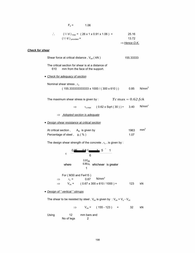
F2 = 1.06
∴ ( l / d ) max = ( 26 x 1 x 0.91 x 1.06 ) = 25.16( l / d ) provided = 13.72
⇒ Hence O.K.
Check for shear
Shear force at critical distance , Vud ( kN ) 155.33333
The critical section for shear is at a distance of 610 mm from the face of the support.
• Check for adequacy of section
Nominal shear stress , τv
( 155.333333333333 x 1000 / ( 300 x 610 ) ) 0.85 N/mm2
The maximum shear stress is given by :
⇒ τc,max ( 0.62 x Sqrt ( 30 ) ) = 3.40 N/mm2
⇒ Adopted section is adequate
• Design shear resistance at critical section
At critical section , Ast is given by 1963 mm2
Percentage of steel , pt ( % ) 1.07
The design shear strength of the concrete , τc , is given by :
For ( M30 and Fe415 ) ⇒ τc = 0.67 N/mm2
⇒ Vuc = ( 0.67 x 300 x 610 / 1000 ) = 123 kN
• Design of " vertical " stirrups
The shear to be resisted by steel , Vus is given by : Vus = Vu - Vuc
⇒ Vus = ( 155 - 123 ) = 32 kN
Using 12 mm bars andNo of legs 2
�c �0.85� �0.8 fck��� 1 5 � 1�
6 �
where � ��0.8fck6.89pt
1whichever is greater
fckTc 62.0max =
198

Area of stirrups , Asv ( mm2 ) 226
⇒ required spacing sv ≤ ( 0.87 x 415 x 226 x 610 / ( 32.12 x 1000 ) )
⇒ Spacing , sv = 1550 mm
Check whether τ v > 0.5 τ c
Nominal shear stress , τv ( N/mm2 ) 0.85Design shear stress , τc ( N/mm2 ) 0.67
τv > 0.5 τc Yes
The Code ( Cl. 26.5.1.6 ) specifies a minimum shear reinforcement to be provided in the form of stirrups in all beams where the calculated nominal shear stress τv
exceeds 0.5 τc. :
The maximum spacing of stirrups should also comply with the requirements mentioned above. For normal " vertical " stirrups, the requirement is
Code requirements for maximum spacing..
i) < ( 2.175 x 415 x 226 / 300 ) = 681 mmii) ≤ ( 0.75 x 609.5 ) = 457 mmiii) ≤ 300 mm 300 mmiv) ≤ ( 0.87 x 415 x 226 x 610 / ( 32.12 x 1000 ) ) = 1550 mm
sv ��0.75 d300 mm
bfyAsv
tcsvWhenfyb
A
sv
sv
sv
175.2
5.087.0
4.0
=
==
199

Beam RB2 Mid
Design Parameters
Load Case 14 [1.5*(DL - EQX)]Grade of Concrete M30Grade of Steel Fe415Characteristic compressive strength of concrete , fck ( N/mm2 ) 30Characteristic yield strength of steel , fy ( N/mm2 ) 415Unit weight of concrete , γc ( kN/m3 ) 24Partial safety factor for concrete 1.5Exposure condition MildNominal Cover to exposure condition( mm ) 20
Dimensions of the beam
C/C Span of the beam , l , ( m ) 5.36Breadth of the beam , b ( mm ) 300Overall depth of the beam , D ( mm ) 400
Details of reinforcements
Diameter of tension reinforcement ( mm ) 25 Diameter of compression reinforcement ( mm ) 25Diameter of stirrups ( mm ) 8
Effective depth
Effective depth , d ( mm ) ( 650-20-8-25/2 ) = 610
Design Moment, Shear Force
The moments and shears given below are taken from the STAAD.Pro 2004 output file.The partial factors of safety are already incorporated into the analysis.
Torsional Moment 16 kN-mBending Moment Mu(kN-m) 190Equivalent Bending Moment , Me ( kNm ) 220Shear force at critical distance , Vud ( kN ) 165Equivalent Shear (kN) 250
Singly reinforced or doubly reinforced section ?
The limiting moment of resistance , Mu,lim is given by
The limiting percentage of steel , pt,lim is given by
SectiontheofdepthEffectivedAxisNeutralofdepthLimitingxu
SectiontheofBreadthbWhere
0.416xu*d
bxu*0.362fckMulim
max
maxmax
==
=
=
200

The area of steel for a singly reinforced section with width , b and depth , d and ultimate moment , Mu is given by :
For ( M30 and Fe415 )
xu,max / d = 0.48
⇒ Mu,lim = ( 0.1389 x 30 x 300 x 609.5^2 / 1000000 ) = 464.40 kNm
⇒ pt,lim = ( 41.3 x 30 / 415 x 0.48 ) = 1.433
If Mu > Mu,lim , the section has to be i) get increased by depth or width ( preferably depth )ii) doubly reinforced
If Mu < Mu,lim , the section can be designed as singly reinforced.
Check for the type of section
Mu = 219.80 kNmMu,lim = 464.40 kNm
⇒ Section can be designed as singly reinforced.
Determining A st
• Considering a ' balanced section ' ( xu = xu,max )Ast = Ast,lim + ΔAst
where Ast,lim = pt,lim / 100 ( b x d )
⇒ Ast,lim ( 1.433 / 100 x 300 x 609.5 ) = 2620 mm2
• Assuming 25 mm bars for compression steel,
d' ≈ ( 20 mm clear cover + 8 mm stirrup + 25 / 2 ) = 40.5 mm
Mu,lim � 0.1389 fck b d2
steelofstrengthticCharcterisfyconcreteofstrengtheCompressivticCharcterisfckWhere
dxu*
fyfck*41.61Pt max
lim
==
=
2
598.42100
bdMuRWhere
fR
fyfckx
bdAstxPt
ck
=
=
201

Mu = 0.87*fy**Ast*d(1-(Ast*fy)/b*d*fck)
Ast Reqd = 1088 mm2
∴ No of tension bars required ( # )( 1088 / ( Pi / 4 x 25^2 ) = 3.00
Actual percentage of steel , pt ( % )( 3 x Pi / 4 x 25 ^2 / 300 / 610 x 100 ) = 0.81
Actual area of steel , Ast ( mm2 )( 3 x Pi / 4 x 25 ^2 ) = 1473
Determining A sc
The compression steel , Asc , is given by
or
where fsc is the stress in compression steel.
The values of fsc ( in MPa units ) at xu = xu,max for variousd' / d ratios and different grades of compression steel are given in the table below.
• Assuming xu = xu,max , for d' / d = ( 40.5 / 609.5 ) = 0.066From the above table : by interpolation
Design Check
• To ensure xu ≤ xu,max , it suffices to establish pc ≥ pc*
�Ast ��Mu Mu,lim�0.87 fy�d d'
�pt100
�R Rlim
0.87 fy�1 d'd
Asc ��0.87 fy���Ast
fsc 0.447 fck
pc �0.87 fy�pt pt,lim
fsc 0.447 fck
Grade of steel d'd
0.05 0.10 0.15 0.20Fe250 217.5 217.5 217.5 217.5Fe415 355.1 351.9 342.4 329.2Fe500 423.9 411.3 395.1 370.3
202

where pc* is given by
Actual pt provided : pt = 0.81Actual pc provided : pc = 0.81
⇒ pc* = ( 0.87 x 415 x ( 0.805 - 1.433 ) / ( 355.03 - 0.447 x 30 ) )
⇒ pc* = -0.66
Section is not over reinforced
Check for deflection control
For prismatic beams of rectangular sections and slabs of uniform thicknesses and spans upto 10m , the limiting l / d ratios are specified by the Code ( Cl. 23.2.1 ) as :
The modification factors F1 ( which varies with pt and fst )and F2 ( which varies with pc ) are as given in Fig .4 and Fig .5 of the code.
Code permits an approximate calculation of fst as follows :
⇒ fst = ( 0.58 x 415 x 1430 / 1473 ) = 233.69 N/mm2
F = 1.00F1 = 1.19
pc �
0.87 fy�fsc 0.447 fck��pt pt,lim
�ld�max
��ld�basic
F1 F2
where �ld�basic
���������7 for cantilever spans20 for simply supported spans
26 for continuous spans
For simply supported and continuous spans over10 m, these ratios are multiplied by a factor F
F �10
span in metres
203
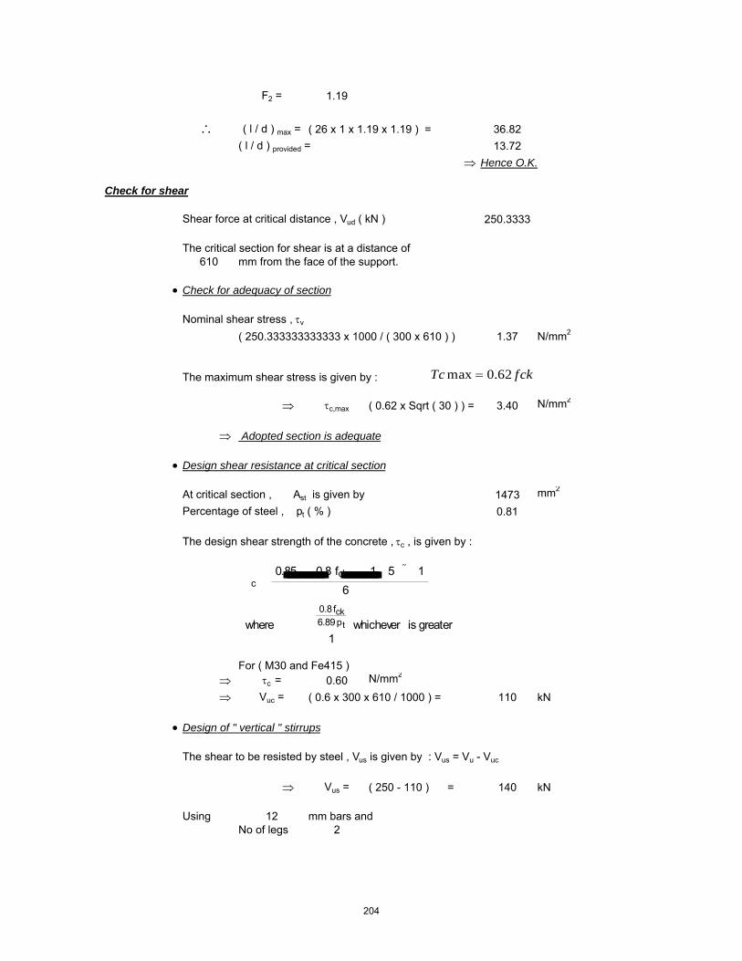
F2 = 1.19
∴ ( l / d ) max = ( 26 x 1 x 1.19 x 1.19 ) = 36.82( l / d ) provided = 13.72
⇒ Hence O.K.
Check for shear
Shear force at critical distance , Vud ( kN ) 250.3333
The critical section for shear is at a distance of 610 mm from the face of the support.
• Check for adequacy of section
Nominal shear stress , τv
( 250.333333333333 x 1000 / ( 300 x 610 ) ) 1.37 N/mm2
The maximum shear stress is given by :
⇒ τc,max ( 0.62 x Sqrt ( 30 ) ) = 3.40 N/mm2
⇒ Adopted section is adequate
• Design shear resistance at critical section
At critical section , Ast is given by 1473 mm2
Percentage of steel , pt ( % ) 0.81
The design shear strength of the concrete , τc , is given by :
For ( M30 and Fe415 ) ⇒ τc = 0.60 N/mm2
⇒ Vuc = ( 0.6 x 300 x 610 / 1000 ) = 110 kN
• Design of " vertical " stirrups
The shear to be resisted by steel , Vus is given by : Vus = Vu - Vuc
⇒ Vus = ( 250 - 110 ) = 140 kN
Using 12 mm bars andNo of legs 2
�c �0.85� �0.8 fck��� 1 5 � 1�
6 �
where � ��0.8fck6.89pt
1whichever is greater
fckTc 62.0max =
204

Area of stirrups , Asv ( mm2 ) 226
⇒ required spacing sv ≤ ( 0.87 x 415 x 226 x 610 / ( 140.11 x 1000 ) )
⇒ Spacing , sv = 355 mm
Check whether τ v > 0.5 τ c
Nominal shear stress , τv ( N/mm2 ) 1.37Design shear stress , τc ( N/mm2 ) 0.60
τv > 0.5 τc Yes
The Code ( Cl. 26.5.1.6 ) specifies a minimum shear reinforcement to be provided in the form of stirrups in all beams where the calculated nominal shear stress τv
exceeds 0.5 τc. :
The maximum spacing of stirrups should also comply with the requirements mentioned above. For normal " vertical " stirrups, the requirement is
Code requirements for maximum spacing..
i) < ( 2.175 x 415 x 226 / 300 ) = 681 mmii) ≤ ( 0.75 x 609.5 ) = 457 mmiii) ≤ 300 mm 300 mmiv) ≤ ( 0.87 x 415 x 226 x 610 / ( 140.11 x 1000 ) ) = 355 mm
sv ��0.75 d300 mm
bfyAsv
tcsvWhenfyb
A
sv
sv
sv
175.2
5.087.0
4.0
=
==
205

Beam RB3 Support
Design Parameters
Load Case 16 [1.5*(DL - EQZ)]Grade of Concrete M30Grade of Steel Fe415Characteristic compressive strength of concrete , fck ( N/mm2 ) 30Characteristic yield strength of steel , fy ( N/mm2 ) 415Unit weight of concrete , γc ( kN/m3 ) 24Partial safety factor for concrete 1.5Exposure condition MildNominal Cover to exposure condition( mm ) 20
Dimensions of the beam
C/C Span of the beam , l , ( m ) 10.80Breadth of the beam , b ( mm ) 300Overall depth of the beam , D ( mm ) 850
Details of reinforcements
Diameter of tension reinforcement ( mm ) 25 Diameter of compression reinforcement ( mm ) 25Diameter of stirrups ( mm ) 8
Effective depth
Effective depth , d ( mm ) ( 850-20-8-25/2 ) = 810
Design Moment, Shear Force
The moments and shears given below are taken from the STAAD.Pro 2004 output file.The partial factors of safety are already incorporated into the analysis.
Torsional Moment 6 kN-mBending Moment Mu(kN-m) 803Equivalent Bending Moment , Me ( kNm ) 817Shear force at critical distance , Vud ( kN ) 377Equivalent Shear (kN) 409
Singly reinforced or doubly reinforced section ?
The limiting moment of resistance , Mu,lim is given by
The limiting percentage of steel , pt,lim is given by
SectiontheofdepthEffectivedAxisNeutralofdepthLimitingxu
SectiontheofBreadthbWhere
0.416xu*d
bxu*0.362fckMulim
max
maxmax
==
=
=
206
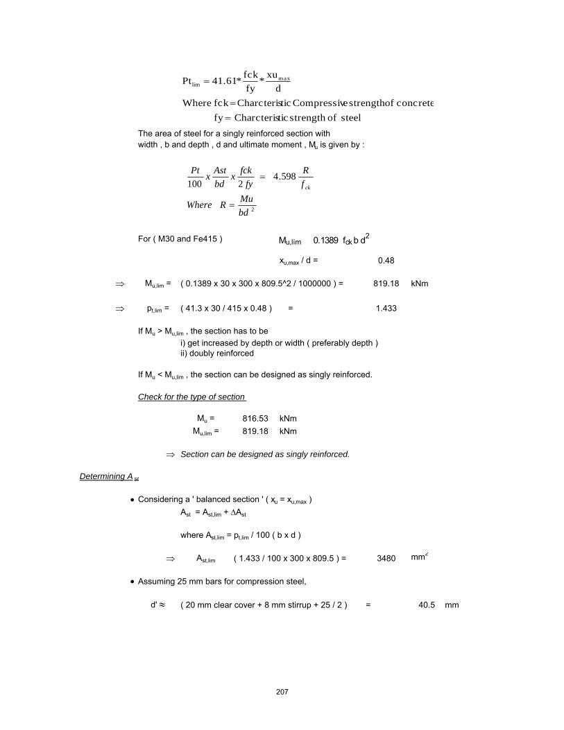
The area of steel for a singly reinforced section with width , b and depth , d and ultimate moment , Mu is given by :
For ( M30 and Fe415 )
xu,max / d = 0.48
⇒ Mu,lim = ( 0.1389 x 30 x 300 x 809.5^2 / 1000000 ) = 819.18 kNm
⇒ pt,lim = ( 41.3 x 30 / 415 x 0.48 ) = 1.433
If Mu > Mu,lim , the section has to be i) get increased by depth or width ( preferably depth )ii) doubly reinforced
If Mu < Mu,lim , the section can be designed as singly reinforced.
Check for the type of section
Mu = 816.53 kNmMu,lim = 819.18 kNm
⇒ Section can be designed as singly reinforced.
Determining A st
• Considering a ' balanced section ' ( xu = xu,max )Ast = Ast,lim + ΔAst
where Ast,lim = pt,lim / 100 ( b x d )
⇒ Ast,lim ( 1.433 / 100 x 300 x 809.5 ) = 3480 mm2
• Assuming 25 mm bars for compression steel,
d' ≈ ( 20 mm clear cover + 8 mm stirrup + 25 / 2 ) = 40.5 mm
Mu,lim � 0.1389 fck b d2
steelofstrengthticCharcterisfyconcreteofstrengtheCompressivticCharcterisfckWhere
dxu*
fyfck*41.61Pt max
lim
==
=
2
598.42100
bdMuRWhere
fR
fyfckx
bdAstxPt
ck
=
=
207

Mu = 0.87*fy**Ast*d(1-(Ast*fy)/b*d*fck)
Ast Reqd = 3486 mm2
∴ No of tension bars required ( # )( 3486 / ( Pi / 4 x 25^2 ) = 8.00
Actual percentage of steel , pt ( % )( 8 x Pi / 4 x 25 ^2 / 300 / 810 x 100 ) = 1.62
Actual area of steel , Ast ( mm2 )( 8 x Pi / 4 x 25 ^2 ) = 3927
Determining A sc
The compression steel , Asc , is given by
or
where fsc is the stress in compression steel.
The values of fsc ( in MPa units ) at xu = xu,max for variousd' / d ratios and different grades of compression steel are given in the table below.
• Assuming xu = xu,max , for d' / d = ( 40.5 / 809.5 ) = 0.050From the above table : by interpolation
Design Check
• To ensure xu ≤ xu,max , it suffices to establish pc ≥ pc*
�Ast ��Mu Mu,lim�0.87 fy�d d'
�pt100
�R Rlim
0.87 fy�1 d'd
Asc ��0.87 fy���Ast
fsc 0.447 fck
pc �0.87 fy�pt pt,lim
fsc 0.447 fck
Grade of steel d'd
0.05 0.10 0.15 0.20Fe250 217.5 217.5 217.5 217.5Fe415 355.1 351.9 342.4 329.2Fe500 423.9 411.3 395.1 370.3
208

where pc* is given by
Actual pt provided : pt = 1.62Actual pc provided : pc = 0.20
⇒ pc* = ( 0.87 x 415 x ( 1.617 - 1.433 ) / ( 355.1 - 0.447 x 30 ) )
⇒ pc* = 0.19
Section is not over reinforced
Check for deflection control
For prismatic beams of rectangular sections and slabs of uniform thicknesses and spans upto 10m , the limiting l / d ratios are specified by the Code ( Cl. 23.2.1 ) as :
The modification factors F1 ( which varies with pt and fst )and F2 ( which varies with pc ) are as given in Fig .4 and Fig .5 of the code.
Code permits an approximate calculation of fst as follows :
⇒ fst = ( 0.58 x 415 x 3471 / 3927 ) = 212.73 N/mm2
F = 0.93F1 = 0.83
pc �
0.87 fy�fsc 0.447 fck��pt pt,lim
�ld�max
��ld�basic
F1 F2
where �ld�basic
���������7 for cantilever spans20 for simply supported spans
26 for continuous spans
For simply supported and continuous spans over10 m, these ratios are multiplied by a factor F
F �10
span in metres
209

F2 = 0.68
∴ ( l / d ) max = ( 26 x 0.93 x 0.83 x 0.68 ) = 13.48( l / d ) provided = 13.34
⇒ Hence O.K.
Check for shear
Shear force at critical distance , Vud ( kN ) 409
The critical section for shear is at a distance of 810 mm from the face of the support.
• Check for adequacy of section
Nominal shear stress , τv
( 409 x 1000 / ( 300 x 810 ) ) = 1.68 N/mm2
The maximum shear stress is given by :
⇒ τc,max ( 0.62 x Sqrt ( 30 ) ) = 3.40 N/mm2
⇒ Adopted section is adequate
• Design shear resistance at critical section
At critical section , Ast is given by 3927 mm2
Percentage of steel , pt ( % ) 1.62
The design shear strength of the concrete , τc , is given by :
For ( M30 and Fe415 ) ⇒ τc = 0.78 N/mm2
⇒ Vuc = ( 0.78 x 300 x 810 / 1000 ) = 190 kN
• Design of " vertical " stirrups
The shear to be resisted by steel , Vus is given by : Vus = Vu - Vuc
⇒ Vus = ( 409 - 190 ) = 219 kN
Using 12 mm bars andNo of legs 2
�c �0.85� �0.8 fck��� 1 5 � 1�
6 �
where � ��0.8fck6.89pt
1whichever is greater
fckTc 62.0max =
210

Area of stirrups , Asv ( mm2 ) 226
⇒ required spacing sv ≤ ( 0.87 x 415 x 226 x 810 / ( 218.81 x 1000 ) )
⇒ Spacing , sv = 302 mm
Check whether τ v > 0.5 τ c
Nominal shear stress , τv ( N/mm2 ) 1.68Design shear stress , τc ( N/mm2 ) 0.78
τv > 0.5 τc Yes
The Code ( Cl. 26.5.1.6 ) specifies a minimum shear reinforcement to be provided in the form of stirrups in all beams where the calculated nominal shear stress τv
exceeds 0.5 τc. :
The maximum spacing of stirrups should also comply with the requirements mentioned above. For normal " vertical " stirrups, the requirement is
Code requirements for maximum spacing..
i) < ( 2.175 x 415 x 226 / 300 ) = 681 mmii) ≤ ( 0.75 x 809.5 ) = 607 mmiii) ≤ 300 mm 300 mmiv) ≤ ( 0.87 x 415 x 226 x 810 / ( 218.81 x 1000 ) ) = 302 mm
sv ��0.75 d300 mm
bfyAsv
tcsvWhenfyb
A
sv
sv
sv
175.2
5.087.0
4.0
=
==
211
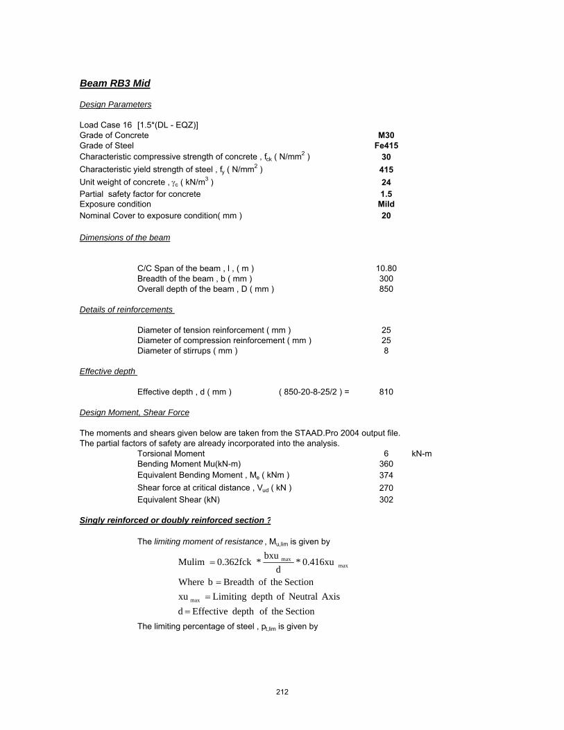
Beam RB3 Mid
Design Parameters
Load Case 16 [1.5*(DL - EQZ)]Grade of Concrete M30Grade of Steel Fe415Characteristic compressive strength of concrete , fck ( N/mm2 ) 30Characteristic yield strength of steel , fy ( N/mm2 ) 415Unit weight of concrete , γc ( kN/m3 ) 24Partial safety factor for concrete 1.5Exposure condition MildNominal Cover to exposure condition( mm ) 20
Dimensions of the beam
C/C Span of the beam , l , ( m ) 10.80Breadth of the beam , b ( mm ) 300Overall depth of the beam , D ( mm ) 850
Details of reinforcements
Diameter of tension reinforcement ( mm ) 25 Diameter of compression reinforcement ( mm ) 25Diameter of stirrups ( mm ) 8
Effective depth
Effective depth , d ( mm ) ( 850-20-8-25/2 ) = 810
Design Moment, Shear Force
The moments and shears given below are taken from the STAAD.Pro 2004 output file.The partial factors of safety are already incorporated into the analysis.
Torsional Moment 6 kN-mBending Moment Mu(kN-m) 360Equivalent Bending Moment , Me ( kNm ) 374Shear force at critical distance , Vud ( kN ) 270Equivalent Shear (kN) 302
Singly reinforced or doubly reinforced section ?
The limiting moment of resistance , Mu,lim is given by
The limiting percentage of steel , pt,lim is given by
SectiontheofdepthEffectivedAxisNeutralofdepthLimitingxu
SectiontheofBreadthbWhere
0.416xu*d
bxu*0.362fckMulim
max
maxmax
==
=
=
212

The area of steel for a singly reinforced section with width , b and depth , d and ultimate moment , Mu is given by :
For ( M30 and Fe415 )
xu,max / d = 0.48
⇒ Mu,lim = ( 0.1389 x 30 x 300 x 809.5^2 / 1000000 ) = 819.18 kNm
⇒ pt,lim = ( 41.3 x 30 / 415 x 0.48 ) = 1.433
If Mu > Mu,lim , the section has to be i) get increased by depth or width ( preferably depth )ii) doubly reinforced
If Mu < Mu,lim , the section can be designed as singly reinforced.
Check for the type of section
Mu = 373.53 kNmMu,lim = 819.18 kNm
⇒ Section can be designed as singly reinforced.
Determining A st
• Considering a ' balanced section ' ( xu = xu,max )Ast = Ast,lim + ΔAst
where Ast,lim = pt,lim / 100 ( b x d )
⇒ Ast,lim ( 1.433 / 100 x 300 x 809.5 ) = 3480 mm2
• Assuming 25 mm bars for compression steel,
d' ≈ ( 20 mm clear cover + 8 mm stirrup + 25 / 2 ) = 40.5 mm
Mu,lim � 0.1389 fck b d2
steelofstrengthticCharcterisfyconcreteofstrengtheCompressivticCharcterisfckWhere
dxu*
fyfck*41.61Pt max
lim
==
=
2
598.42100
bdMuRWhere
fR
fyfckx
bdAstxPt
ck
=
=
213

Mu = 0.87*fy**Ast*d(1-(Ast*fy)/b*d*fck)
Ast Reqd = 1388 mm2
∴ No of tension bars required ( # )( 1388 / ( Pi / 4 x 25^2 ) = 3.00
Actual percentage of steel , pt ( % )( 3 x Pi / 4 x 25 ^2 / 300 / 810 x 100 ) = 0.61
Actual area of steel , Ast ( mm2 )( 3 x Pi / 4 x 25 ^2 ) = 1473
Determining A sc
The compression steel , Asc , is given by
or
where fsc is the stress in compression steel.
The values of fsc ( in MPa units ) at xu = xu,max for variousd' / d ratios and different grades of compression steel are given in the table below.
• Assuming xu = xu,max , for d' / d = ( 40.5 / 809.5 ) = 0.050From the above table : by interpolation
Design Check
• To ensure xu ≤ xu,max , it suffices to establish pc ≥ pc*
�Ast ��Mu Mu,lim�0.87 fy�d d'
�pt100
�R Rlim
0.87 fy�1 d'd
Asc ��0.87 fy���Ast
fsc 0.447 fck
pc �0.87 fy�pt pt,lim
fsc 0.447 fck
Grade of steel d'd
0.05 0.10 0.15 0.20Fe250 217.5 217.5 217.5 217.5Fe415 355.1 351.9 342.4 329.2Fe500 423.9 411.3 395.1 370.3
214

where pc* is given by
Actual pt provided : pt = 0.61Actual pc provided : pc = 0.81
⇒ pc* = ( 0.87 x 415 x ( 0.606 - 1.433 ) / ( 355.1 - 0.447 x 30 ) )
⇒ pc* = -0.87
Section is not over reinforced
Check for deflection control
For prismatic beams of rectangular sections and slabs of uniform thicknesses and spans upto 10m , the limiting l / d ratios are specified by the Code ( Cl. 23.2.1 ) as :
The modification factors F1 ( which varies with pt and fst )and F2 ( which varies with pc ) are as given in Fig .4 and Fig .5 of the code.
Code permits an approximate calculation of fst as follows :
⇒ fst = ( 0.58 x 415 x 1875 / 1473 ) = 306.48 N/mm2
F = 0.93F1 = 1.11
pc �
0.87 fy�fsc 0.447 fck��pt pt,lim
�ld�max
��ld�basic
F1 F2
where �ld�basic
���������7 for cantilever spans20 for simply supported spans
26 for continuous spans
For simply supported and continuous spans over10 m, these ratios are multiplied by a factor F
F �10
span in metres
215

F2 = 1.19
∴ ( l / d ) max = ( 26 x 0.93 x 1.11 x 1.19 ) = 31.96( l / d ) provided = 13.34
⇒ Hence O.K.
Check for shear
Shear force at critical distance , Vud ( kN ) 302
The critical section for shear is at a distance of 810 mm from the face of the support.
• Check for adequacy of section
Nominal shear stress , τv
( 302 x 1000 / ( 300 x 810 ) ) = 1.24 N/mm2
The maximum shear stress is given by :
⇒ τc,max ( 0.62 x Sqrt ( 30 ) ) = 3.40 N/mm2
⇒ Adopted section is adequate
• Design shear resistance at critical section
At critical section , Ast is given by 1473 mm2
Percentage of steel , pt ( % ) 0.61
The design shear strength of the concrete , τc , is given by :
For ( M30 and Fe415 ) ⇒ τc = 0.54 N/mm2
⇒ Vuc = ( 0.54 x 300 x 810 / 1000 ) = 131 kN
• Design of " vertical " stirrups
The shear to be resisted by steel , Vus is given by : Vus = Vu - Vuc
⇒ Vus = ( 302 - 131 ) = 171 kN
Using 12 mm bars andNo of legs 2
�c �0.85� �0.8 fck��� 1 5 � 1�
6 �
where � ��0.8fck6.89pt
1whichever is greater
fckTc 62.0max =
216

Area of stirrups , Asv ( mm2 ) 226
⇒ required spacing sv ≤ ( 0.87 x 415 x 226 x 810 / ( 171.38 x 1000 ) )
⇒ Spacing , sv = 386 mm
Check whether τ v > 0.5 τ c
Nominal shear stress , τv ( N/mm2 ) 1.24Design shear stress , τc ( N/mm2 ) 0.54
τv > 0.5 τc Yes
The Code ( Cl. 26.5.1.6 ) specifies a minimum shear reinforcement to be provided in the form of stirrups in all beams where the calculated nominal shear stress τv
exceeds 0.5 τc. :
The maximum spacing of stirrups should also comply with the requirements mentioned above. For normal " vertical " stirrups, the requirement is
Code requirements for maximum spacing..
i) < ( 2.175 x 415 x 226 / 300 ) = 681 mmii) ≤ ( 0.75 x 809.5 ) = 607 mmiii) ≤ 300 mm 300 mmiv) ≤ ( 0.87 x 415 x 226 x 810 / ( 171.38 x 1000 ) ) = 386 mm
sv ��0.75 d300 mm
bfyAsv
tcsvWhenfyb
A
sv
sv
sv
175.2
5.087.0
4.0
=
==
217

Beam RB4 Support
Design Parameters
Load Case 16 [1.5*(DL - EQZ)]Grade of Concrete M30Grade of Steel Fe415Characteristic compressive strength of concrete , fck ( N/mm2 ) 30Characteristic yield strength of steel , fy ( N/mm2 ) 415Unit weight of concrete , γc ( kN/m3 ) 24Partial safety factor for concrete 1.5Exposure condition MildNominal Cover to exposure condition( mm ) 20
Dimensions of the beam
C/C Span of the beam , l , ( m ) 5.50Breadth of the beam , b ( mm ) 300Overall depth of the beam , D ( mm ) 600
Details of reinforcements
Diameter of tension reinforcement ( mm ) 25 Diameter of compression reinforcement ( mm ) 25Diameter of stirrups ( mm ) 8
Effective depth
Effective depth , d ( mm ) ( 600-20-8-25/2 ) = 560
Design Moment, Shear Force
The moments and shears given below are taken from the STAAD.Pro 2004 output file.The partial factors of safety are already incorporated into the analysis.
Torsional Moment 16 kN-mBending Moment Mu(kN-m) 283Equivalent Bending Moment , Me ( kNm ) 311Shear force at critical distance , Vud ( kN ) 90Equivalent Shear (kN) 175
Singly reinforced or doubly reinforced section ?
The limiting moment of resistance , Mu,lim is given by
The limiting percentage of steel , pt,lim is given by
SectiontheofdepthEffectivedAxisNeutralofdepthLimitingxu
SectiontheofBreadthbWhere
0.416xu*d
bxu*0.362fckMulim
max
maxmax
==
=
=
218

The area of steel for a singly reinforced section with width , b and depth , d and ultimate moment , Mu is given by :
For ( M30 and Fe415 )
xu,max / d = 0.48
⇒ Mu,lim = ( 0.1389 x 30 x 300 x 559.5^2 / 1000000 ) = 391.33 kNm
⇒ pt,lim = ( 41.3 x 30 / 415 x 0.48 ) = 1.433
If Mu > Mu,lim , the section has to be i) get increased by depth or width ( preferably depth )ii) doubly reinforced
If Mu < Mu,lim , the section can be designed as singly reinforced.
Check for the type of section
Mu = 311.24 kNmMu,lim = 391.33 kNm
⇒ Section can be designed as singly reinforced.
Determining A st
• Considering a ' balanced section ' ( xu = xu,max )Ast = Ast,lim + ΔAst
where Ast,lim = pt,lim / 100 ( b x d )
⇒ Ast,lim ( 1.433 / 100 x 300 x 559.5 ) = 2405 mm2
• Assuming 25 mm bars for compression steel,
d' ≈ ( 20 mm clear cover + 8 mm stirrup + 25 / 2 ) = 40.5 mm
Mu,lim � 0.1389 fck b d2
steelofstrengthticCharcterisfyconcreteofstrengtheCompressivticCharcterisfckWhere
dxu*
fyfck*41.61Pt max
lim
==
=
2
598.42100
bdMuRWhere
fR
fyfckx
bdAstxPt
ck
=
=
219

Mu = 0.87*fy**Ast*d(1-(Ast*fy)/b*d*fck)
Ast Reqd = 1811 mm2
∴ No of tension bars required ( # )( 1811 / ( Pi / 4 x 25^2 ) = 4.00
Actual percentage of steel , pt ( % )( 4 x Pi / 4 x 25 ^2 / 300 / 560 x 100 ) = 1.17
Actual area of steel , Ast ( mm2 )( 4 x Pi / 4 x 25 ^2 ) = 1963
Determining A sc
The compression steel , Asc , is given by
or
where fsc is the stress in compression steel.
The values of fsc ( in MPa units ) at xu = xu,max for variousd' / d ratios and different grades of compression steel are given in the table below.
• Assuming xu = xu,max , for d' / d = ( 40.5 / 559.5 ) = 0.072From the above table : by interpolation
Design Check
• To ensure xu ≤ xu,max , it suffices to establish pc ≥ pc*
�Ast ��Mu Mu,lim�0.87 fy�d d'
�pt100
�R Rlim
0.87 fy�1 d'd
Asc ��0.87 fy���Ast
fsc 0.447 fck
pc �0.87 fy�pt pt,lim
fsc 0.447 fck
Grade of steel d'd
0.05 0.10 0.15 0.20Fe250 217.5 217.5 217.5 217.5Fe415 355.1 351.9 342.4 329.2Fe500 423.9 411.3 395.1 370.3
220

where pc* is given by
Actual pt provided : pt = 1.17Actual pc provided : pc = 0.29
⇒ pc* = ( 0.87 x 415 x ( 1.17 - 1.433 ) / ( 354.73 - 0.447 x 30 ) )
⇒ pc* = -0.28
Section is not over reinforced
Check for deflection control
For prismatic beams of rectangular sections and slabs of uniform thicknesses and spans upto 10m , the limiting l / d ratios are specified by the Code ( Cl. 23.2.1 ) as :
The modification factors F1 ( which varies with pt and fst )and F2 ( which varies with pc ) are as given in Fig .4 and Fig .5 of the code.
Code permits an approximate calculation of fst as follows :
⇒ fst = ( 0.58 x 415 x 1978 / 1963 ) = 242.47 N/mm2
F = 1.00F1 = 0.91
pc �
0.87 fy�fsc 0.447 fck��pt pt,lim
�ld�max
��ld�basic
F1 F2
where �ld�basic
���������7 for cantilever spans20 for simply supported spans
26 for continuous spans
For simply supported and continuous spans over10 m, these ratios are multiplied by a factor F
F �10
span in metres
221

F2 = 0.82
∴ ( l / d ) max = ( 26 x 1 x 0.91 x 0.82 ) = 19.42( l / d ) provided = 9.83
⇒ Hence O.K.
Check for shear
Shear force at critical distance , Vud ( kN ) 175.33333
The critical section for shear is at a distance of 560 mm from the face of the support.
• Check for adequacy of section
Nominal shear stress , τv
( 175.333333333333 x 1000 / ( 300 x 560 ) ) 1.04 N/mm2
The maximum shear stress is given by :
⇒ τc,max ( 0.62 x Sqrt ( 30 ) ) = 3.40 N/mm2
⇒ Adopted section is adequate
• Design shear resistance at critical section
At critical section , Ast is given by 1963 mm2
Percentage of steel , pt ( % ) 1.17
The design shear strength of the concrete , τc , is given by :
For ( M30 and Fe415 ) ⇒ τc = 0.70 N/mm2
⇒ Vuc = ( 0.7 x 300 x 560 / 1000 ) = 117 kN
• Design of " vertical " stirrups
The shear to be resisted by steel , Vus is given by : Vus = Vu - Vuc
⇒ Vus = ( 175 - 117 ) = 59 kN
Using 12 mm bars andNo of legs 2
�c �0.85� �0.8 fck��� 1 5 � 1�
6 �
where � ��0.8fck6.89pt
1whichever is greater
fckTc 62.0max =
222

Area of stirrups , Asv ( mm2 ) 226
⇒ required spacing sv ≤ ( 0.87 x 415 x 226 x 560 / ( 58.52 x 1000 ) )
⇒ Spacing , sv = 781 mm
Check whether τ v > 0.5 τ c
Nominal shear stress , τv ( N/mm2 ) 1.04Design shear stress , τc ( N/mm2 ) 0.70
τv > 0.5 τc Yes
The Code ( Cl. 26.5.1.6 ) specifies a minimum shear reinforcement to be provided in the form of stirrups in all beams where the calculated nominal shear stress τv
exceeds 0.5 τc. :
The maximum spacing of stirrups should also comply with the requirements mentioned above. For normal " vertical " stirrups, the requirement is
Code requirements for maximum spacing..
i) < ( 2.175 x 415 x 226 / 300 ) = 681 mmii) ≤ ( 0.75 x 559.5 ) = 420 mmiii) ≤ 300 mm 300 mmiv) ≤ ( 0.87 x 415 x 226 x 560 / ( 58.52 x 1000 ) ) = 781 mm
sv ��0.75 d300 mm
bfyAsv
tcsvWhenfyb
A
sv
sv
sv
175.2
5.087.0
4.0
=
==
223

Beam RB4 Mid
Design Parameters
Load Case 16 [1.5*(DL - EQZ)]Grade of Concrete M30Grade of Steel Fe415Characteristic compressive strength of concrete , fck ( N/mm2 ) 30Characteristic yield strength of steel , fy ( N/mm2 ) 415Unit weight of concrete , γc ( kN/m3 ) 24Partial safety factor for concrete 1.5Exposure condition MildNominal Cover to exposure condition( mm ) 20
Dimensions of the beam
C/C Span of the beam , l , ( m ) 5.50Breadth of the beam , b ( mm ) 300Overall depth of the beam , D ( mm ) 600
Details of reinforcements
Diameter of tension reinforcement ( mm ) 20 Diameter of compression reinforcement ( mm ) 20Diameter of stirrups ( mm ) 8
Effective depth
Effective depth , d ( mm ) ( 600-20-8-20/2 ) = 562
Design Moment, Shear Force
The moments and shears given below are taken from the STAAD.Pro 2004 output file.The partial factors of safety are already incorporated into the analysis.
Torsional Moment 0 kN-mBending Moment Mu(kN-m) 120Equivalent Bending Moment , Me ( kNm ) 120Shear force at critical distance , Vud ( kN ) 139Equivalent Shear (kN) 139
Singly reinforced or doubly reinforced section ?
The limiting moment of resistance , Mu,lim is given by
The limiting percentage of steel , pt,lim is given by
SectiontheofdepthEffectivedAxisNeutralofdepthLimitingxu
SectiontheofBreadthbWhere
0.416xu*d
bxu*0.362fckMulim
max
maxmax
==
=
=
224

The area of steel for a singly reinforced section with width , b and depth , d and ultimate moment , Mu is given by :
For ( M30 and Fe415 )
xu,max / d = 0.48
⇒ Mu,lim = ( 0.1389 x 30 x 300 x 562^2 / 1000000 ) = 394.84 kNm
⇒ pt,lim = ( 41.3 x 30 / 415 x 0.48 ) = 1.433
If Mu > Mu,lim , the section has to be i) get increased by depth or width ( preferably depth )ii) doubly reinforced
If Mu < Mu,lim , the section can be designed as singly reinforced.
Check for the type of section
Mu = 120.00 kNmMu,lim = 394.84 kNm
⇒ Section can be designed as singly reinforced.
Determining A st
• Considering a ' balanced section ' ( xu = xu,max )Ast = Ast,lim + ΔAst
where Ast,lim = pt,lim / 100 ( b x d )
⇒ Ast,lim ( 1.433 / 100 x 300 x 562 ) = 2416 mm2
• Assuming 20 mm bars for compression steel,
d' ≈ ( 20 mm clear cover + 8 mm stirrup + 20 / 2 ) = 38 mm
Mu,lim � 0.1389 fck b d2
steelofstrengthticCharcterisfyconcreteofstrengtheCompressivticCharcterisfckWhere
dxu*
fyfck*41.61Pt max
lim
==
=
2
598.42100
bdMuRWhere
fR
fyfckx
bdAstxPt
ck
=
=
225

Mu = 0.87*fy**Ast*d(1-(Ast*fy)/b*d*fck)
Ast Reqd = 623 mm2
∴ No of tension bars required ( # )( 623 / ( Pi / 4 x 20^2 ) = 2.00
Actual percentage of steel , pt ( % )( 2 x Pi / 4 x 20 ^2 / 300 / 562 x 100 ) = 0.37
Actual area of steel , Ast ( mm2 )( 2 x Pi / 4 x 20 ^2 ) = 628
Determining A sc
The compression steel , Asc , is given by
or
where fsc is the stress in compression steel.
The values of fsc ( in MPa units ) at xu = xu,max for variousd' / d ratios and different grades of compression steel are given in the table below.
• Assuming xu = xu,max , for d' / d = ( 38 / 562 ) = 0.068From the above table : by interpolation
Design Check
• To ensure xu ≤ xu,max , it suffices to establish pc ≥ pc*
�Ast ��Mu Mu,lim�0.87 fy�d d'
�pt100
�R Rlim
0.87 fy�1 d'd
Asc ��0.87 fy���Ast
fsc 0.447 fck
pc �0.87 fy�pt pt,lim
fsc 0.447 fck
Grade of steel d'd
0.05 0.10 0.15 0.20Fe250 217.5 217.5 217.5 217.5Fe415 355.1 351.9 342.4 329.2Fe500 423.9 411.3 395.1 370.3
226

where pc* is given by
Actual pt provided : pt = 0.37Actual pc provided : pc = 0.93
⇒ pc* = ( 0.87 x 415 x ( 0.373 - 1.433 ) / ( 354.98 - 0.447 x 30 ) )
⇒ pc* = -1.12
Section is not over reinforced
Check for deflection control
For prismatic beams of rectangular sections and slabs of uniform thicknesses and spans upto 10m , the limiting l / d ratios are specified by the Code ( Cl. 23.2.1 ) as :
The modification factors F1 ( which varies with pt and fst )and F2 ( which varies with pc ) are as given in Fig .4 and Fig .5 of the code.
Code permits an approximate calculation of fst as follows :
⇒ fst = ( 0.58 x 415 x 963 / 628 ) = 369.08 N/mm2
F = 1.00F1 = 1.26
pc �
0.87 fy�fsc 0.447 fck��pt pt,lim
�ld�max
��ld�basic
F1 F2
where �ld�basic
���������7 for cantilever spans20 for simply supported spans
26 for continuous spans
For simply supported and continuous spans over10 m, these ratios are multiplied by a factor F
F �10
span in metres
227

F2 = 1.24
∴ ( l / d ) max = ( 26 x 1 x 1.26 x 1.24 ) = 40.32( l / d ) provided = 9.79
⇒ Hence O.K.
Check for shear
Shear force at critical distance , Vud ( kN ) 139
The critical section for shear is at a distance of 562 mm from the face of the support.
• Check for adequacy of section
Nominal shear stress , τv
( 139 x 1000 / ( 300 x 562 ) ) = 0.82 N/mm2
The maximum shear stress is given by :
⇒ τc,max ( 0.62 x Sqrt ( 30 ) ) = 3.40 N/mm2
⇒ Adopted section is adequate
• Design shear resistance at critical section
At critical section , Ast is given by 628 mm2
Percentage of steel , pt ( % ) 0.37
The design shear strength of the concrete , τc , is given by :
For ( M30 and Fe415 ) ⇒ τc = 0.44 N/mm2
⇒ Vuc = ( 0.44 x 300 x 562 / 1000 ) = 74 kN
• Design of " vertical " stirrups
The shear to be resisted by steel , Vus is given by : Vus = Vu - Vuc
⇒ Vus = ( 139 - 74 ) = 65 kN
Using 8 mm bars andNo of legs 2
�c �0.85� �0.8 fck��� 1 5 � 1�
6 �
where � ��0.8fck6.89pt
1whichever is greater
fckTc 62.0max =
228
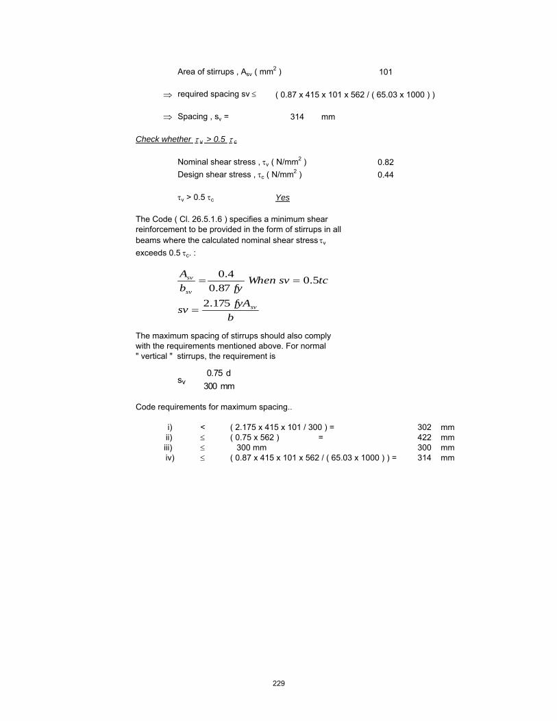
Area of stirrups , Asv ( mm2 ) 101
⇒ required spacing sv ≤ ( 0.87 x 415 x 101 x 562 / ( 65.03 x 1000 ) )
⇒ Spacing , sv = 314 mm
Check whether τ v > 0.5 τ c
Nominal shear stress , τv ( N/mm2 ) 0.82Design shear stress , τc ( N/mm2 ) 0.44
τv > 0.5 τc Yes
The Code ( Cl. 26.5.1.6 ) specifies a minimum shear reinforcement to be provided in the form of stirrups in all beams where the calculated nominal shear stress τv
exceeds 0.5 τc. :
The maximum spacing of stirrups should also comply with the requirements mentioned above. For normal " vertical " stirrups, the requirement is
Code requirements for maximum spacing..
i) < ( 2.175 x 415 x 101 / 300 ) = 302 mmii) ≤ ( 0.75 x 562 ) = 422 mmiii) ≤ 300 mm 300 mmiv) ≤ ( 0.87 x 415 x 101 x 562 / ( 65.03 x 1000 ) ) = 314 mm
sv ��0.75 d300 mm
bfyAsv
tcsvWhenfyb
A
sv
sv
sv
175.2
5.087.0
4.0
=
==
229

DESIGN OF SLAB
230

Design of Grid Slab
Grade of concrete = 30 KN/m2
Grade of steel = 415 N/mm2
Unit weight of concrete = 24 kN/m3
Live Load = 3 kN/m2
Cover = 20 mmRoof Finish Load = 1 kN/m2
Ly 8.36 mLx 4.96 m
Aspect Ratio r = 1.69= 4 2
Grid Spacing =X - Dir = 1.240 mY - Dir = 1.400 m
No of Beams in X - Direction = 3 NosNo of Beams in Y - Direction = 5 Nos
Thickness of the Slab Df = 120 mmThickness of the Web bw = 250 mmDepth of the Web D = 430 mm
Df = 120 mm
D = 430 310
Design of the Section :
Self weight of Slab = 2.88 kN/m2
Total Load of Slab = 119.42 kNWeight of Rib = 1.86 kN/mTotal weight of Beams (x-direction) = 45.86 kNTotal weight of Beams (y-direction) = 39.71 kNTotal weight of Floor Finish = 41.4656 kNTotal Live Load = 124.3968 kN
Total Load = 370.9 kN/m2
Load per m2 q = 8.9 kN/m2
bf = 1400 mm
bw = 250 mm
231

Approximate Method (Moments)
If q1 & q2 are the moments shared in the x & y directions
q1 = 8.0 kN/m2
q1 = 1.0
Moments in x & y directions at centre of grid for 2 m width is tained as :
Mx = 30.5 kN.m
My = 12.1 kN.m
Qx = 24.6 kNQy = 5.8 kN
Design of Reinforcement
Max working moment Mw = 18.3 kN.m/m
Moment resisted by central rib inx-direction over 1.24 m width = 22.7 kN.m
Ultimate moment Mu = 34.0 kN.m
Moment capacity of flange section
Muf = 513.6 kN.m
Mu<Muf N.A falls within the Flange
⎟⎟⎠
⎞⎜⎜⎝
⎛
+= 44
4
1yx
y
bab
⎟⎟⎠
⎞⎜⎜⎝
⎛
+= 44
4
2yx
x
baaqq
⎟⎟⎠
⎞⎜⎜⎝
⎛=
8
211 abqMx
⎟⎟⎠
⎞⎜⎜⎝
⎛=
8
212 baqMy
)42.0(..36.0 fffckuf DdDbfM −=
232
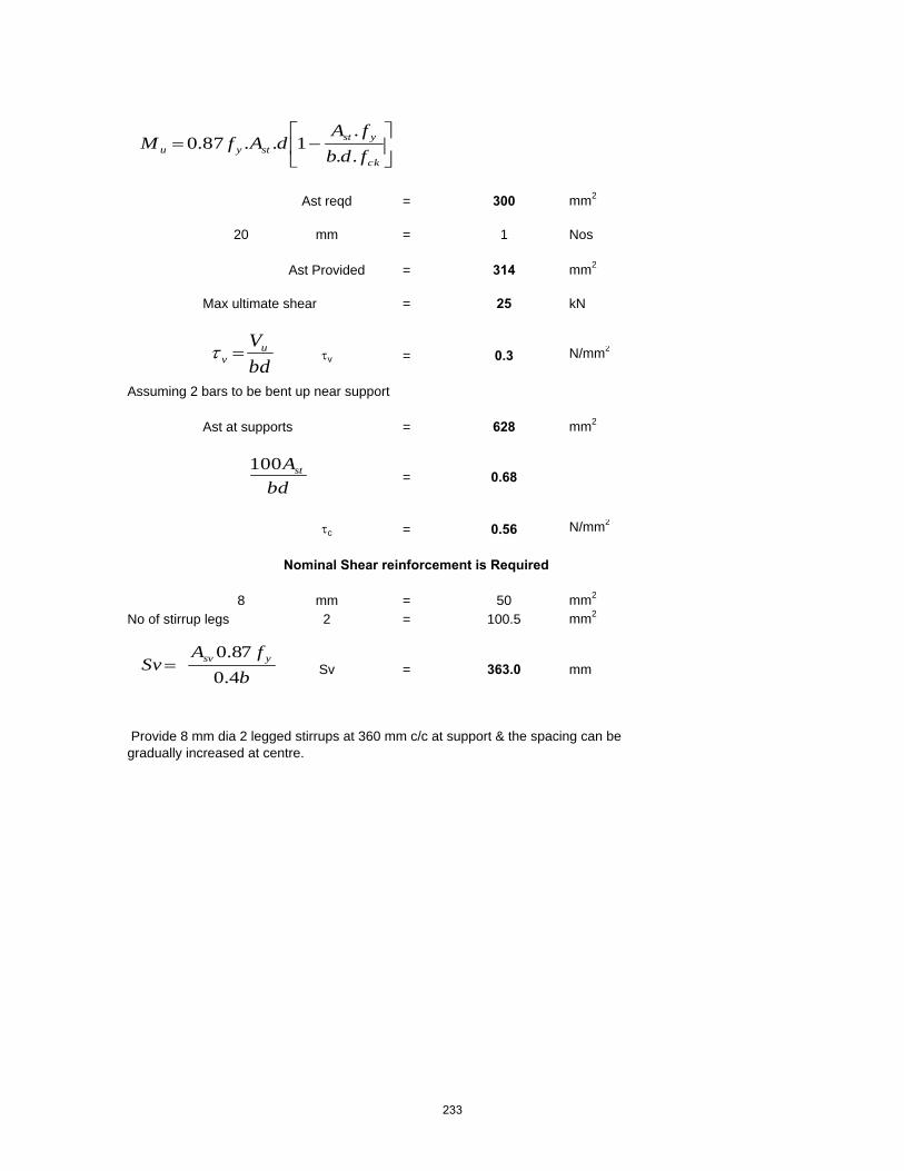
Ast reqd = 300 mm2
20 mm = 1 Nos
Ast Provided = 314 mm2
Max ultimate shear = 25 kN
τv = 0.3 N/mm2
Assuming 2 bars to be bent up near support
Ast at supports = 628 mm2
= 0.68
τc = 0.56 N/mm2
Nominal Shear reinforcement is Required
8 mm = 50 mm2
No of stirrup legs 2 = 100.5 mm2
Sv = 363.0 mm
Provide 8 mm dia 2 legged stirrups at 360 mm c/c at support & the spacing can be gradually increased at centre.
⎥⎦
⎤⎢⎣
⎡−=
ck
yststyu fdb
fAdAfM
...
1..87.0
bdVu
v =τ
bdAst100
bfA
Sv ysv
4.087.0
=
233
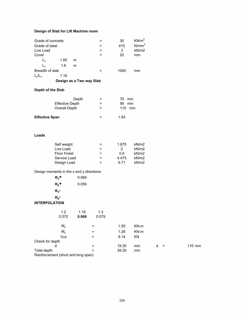
Design of Slab for Lift Machine room
Grade of concrete = 30 KN/m2
Grade of steel = 415 N/mm2
Live Load = 3 kN/m2Cover = 20 mm
Ly 1.85 mLx 1.6 m
Breadth of slab = 1000 mmLy/Lx 1.16
Design as a Two way Slab
Depth of the Slab
Depth = 70 mmEffective Depth = 95 mmOverall Depth = 115 mm
Effective Span = 1.83
Loads
Self weight = 1.875 kN/m2Live Load = 2 kN/m2Floor Finish = 0.6 kN/m2Service Load = 4.475 kN/m2Design Load = 6.71 kN/m2
Design moments in the x and y directionsαx+ 0.069
αy+ 0.056
αx-αy-
INTERPOLATION
1.2 1.16 1.30.072 0.069 0.079
Mx = 1.55 KN-mMy = 1.26 KN-m
Vux = 6.14 KNCheck for depth
d = 19.35 mm d = 110 mmTotal depth = 39.35 mmReinforcement (short and long span)
234

Shorter span Longer spana = 4.99 4.99b = 36105.00 36105.00c = 1549679.93 1258851.51b2-4ac = 1272611364 12784215642a = 9.99 9.99SQ = 35673.68 35755.02Ast1 = 43.18 mm2
35.04 mm2
Ast2 = -7185.73627 mm2-7193.87945
Reinforcement in Shorter Directionspacing of 10 mm = 1818 mm c/c spacing of 12 mm = 2619 mm c/c Provide 12 mm bars at 150 mm c/c Reinforcement in Longer Directionspacing of 10 mm = 2241 mm c/c spacing of 12 mm = 3228 mm c/c Provide 12 mm bars at 150 mm c/c Check for shear stress
Considering the short span & unit width of slab
ζv = Vu / bd= 0.0614 N/mm2
Pt = 0.043INTERPOLATION
0.5 0.04 0.75 Table190.48 0.334 0.56
ζc = 0.334 N/mm2
ζc > ζv Shear reinforcement is not reqdCheck for deflection ControlModification Factor From IS 456
K = 1.2
235

Design of Slab for Ramp
Grade of concrete = 30 KN/m2
Grade of steel = 415 N/mm2
Live Load = 4 kN/m2Cover = 20 mm
Ly 5.345 mLx 3.6 m
Breadth of slab = 1000 mmLy/Lx 1.48
Design as a Two way Slab
Depth of the Slab
Depth = 112.5 mmEffective Depth = 112.5 mmOverall Depth = 137.5 mm
Effective Span = 3.83
Loads
Self weight = 3.4375 kN/m2Live Load = 4 kN/m2Floor Finish = 0.6 kN/m2Service Load = 8.0375 kN/m2Design Load = 12.06 kN/m2
Design moments in the x and y directionsαx+ 0.092
αy+ 0.056
αx-αy-
INTERPOLATION
1.2 1.48 1.30.072 0.092 0.079
Mx = 16.26 KN-mMy = 9.90 KN-m
Vux = 23.09 KNCheck for depth
d = 62.67 mm d = 130 mmTotal depth = 82.67 mmReinforcement (short and long span)
Shorter span Longer spana = 4.99 4.99b = 46936.50 46936.50c = 16258095.77 9903707.84b2-4ac = 1878229169 20051777672a = 9.99 9.99SQ = 43338.54 44779.21Ast1 = 360.19 mm2
215.97 mm2
Ast2 = -9037.40009 mm2-9181.625012
Reinforcement in Shorter Directionspacing of 10 mm = 218 mm c/c spacing of 12 mm = 314 mm c/c Provide 12 mm bars at 100 mm c/c Reinforcement in Longer Directionspacing of 10 mm = 363 mm c/c spacing of 12 mm = 524 mm c/c Provide 12 mm bars at 150 mm c/c Check for shear stress
Considering the short span & unit width of slab
ζv = Vu / bd
236

= 0.1776 N/mm2
Pt = 0.277INTERPOLATION
0.5 0.28 0.75 Table190.48 0.409 0.56
ζc = 0.409 N/mm2
ζc > ζv Shear reinforcement is not reqdCheck for deflection ControlModification Factor From IS 456
K = 1.2
237

BILL OF QUANTITIES

Sl. No SOR Ref No
Description of Work Unit Quantity Rate (Rs) Amount (Rs)
1.01 251a Excavation in foundation in ordinary soil ( loam, clay or sand) including lift upto 1.5m and lead upto 30m and includingfilling watering and ramming of excavated earth into thetrenches or into the space between the building and the sidesof the foundation trenches or into the plinth and removal anddisposal of surplus earth as directed by engineer in chargeupto a distance of 30m from the foundation trenches
cum 4,569.00 38.00 173,622.00
1.01a 254a Extra for every additional 30m lead or part of 30m or forevery additional 1.5m lift or part of 1.50m
cum 3,040.00 43.00 130,720.00
1.01b 254a Extra for every additional 30m lead or part of 30m or forevery additional 1.5m lift or part of 1.50m
cum 183.00 48.00 8,784.00
1.02 255a Sand filling in plinth including supply of necessary quantity ofsand from a distance not exceeding 8 km from the site ofwork and including watering, dressing etc labour and T&P etcrequired for the proper completion of the work, saplings ofgirth upto 30cm measured at a height of 1m above groundlevel and removal of rubbish upto a distance of 50m outsidethe periphery of area cleared
cum 4,560.00 220.00 1,003,200.00
1.03 2.27 CPWD
Supplying and filling in plinth with Jamuna sand underfloors including, watering, ramming consolidating anddressing complete.
cum 852.27 331.65 282,656.00
1.04 281 Cement concrete with 40mm gauge approved stone ballast,coarse sand& cement in the proportion of 8:4:1 includingsupply of all materials , labour, tools & plants etc. required forproper completion of the work.
cum 469.00 2,500.00 1,172,500.00
1.05 5.33 CPWD
Providing and laying in position machine batched, machinemixed and machine vibrated design mix cement concreteof specified grade for reinforced cement concrete workincluding pumping of concrete to site of laying butexcluding the cost of centering, shuttering, finishing andreinforcement. including Admixtures in recommendedproportions as per IS 9103 to accelerate, retard setting ofconcrete, improve workability without impairing strength anddurability as per direction of Engineer-in-charge. M-25 gradereinforced cement concrete by using 410kg. of cement percum of concrete. All work up to floor V level.
cum 21,148.00 4,147.40 87,709,215.00
1.05a 5.34.1 CPWD
Add or deduct for providing richer or leaner mixesrespectively at all floor levels. Providing M-30 gradeconcrete by using 420kg of cement per cum of concreteinstead of M-25 grade B.M.C/ R.M.C..
cum 21,148.00 54.55 1,153,623.00
1.06 504 M.S ( Tor steel or Plain ) in plain work such as RCC or R.Bwork including bending for proper shape and including supplyof steel and its wastage, bends hooks and authorisedoverlapping shall be measured and including cost of bindingwire.
MT 3,984.61 49,000.00 195,246,106.00
1.07 M-150 Brick work in 1:6 one cement and six fine sand mortarincluding necessary cutting and moulding of brick as requiredof one brick thick including supply of all materials labour toolsand plant etc required for proper completion of the work.
1.07a 303 In Foundation cum 321.00 1,900.00 609,900.00 1.07b 310 Extra for Superstructure cum 321.00 185.00 59,385.00
Total Carried Forward 287,549,711.00
ARCHITECTURAL & STRUCTURAL WORKS
1 of 3

Sl. No SOR Ref No
Description of Work Unit Quantity Rate (Rs) Amount (Rs)
Total Brought Forward 287,549,711.00 1.08 13.7.2
CPWD 12 mm cement plaster finished with a floating coat of neatcement of mix :1:4 (1 cement: 4 fine sand)
sqm 1,604.00 97.90 157,032.00
1.09 13.8.2 CPWD
15 mm cement plaster on rough side of single or half brickwall finished with a floating coat of neat cement of mix : 1:4(1 cement: 4 fine sand)
sqm 1,604.00 110.70 177,563.00
1.10 13.16 CPWD
Plastering with CM 1:3 mix (one cement and three sand)6mm thick including cost, conveyance, labour charges etc.complete as per standard specification- for ceiling
sqm 32,134.00 62.15 1,997,128.00
1.11 13.48.1 CPWD
Finishing walls with Deluxe Multi surface paint system forinteriors and exteriors using Primer as per manufacturersspecifications :Two or more coats applied @ 1.25 ltr/10sqm. over and including one coat of Special primer applied@ 0.75 ltr / 10 sqm.
sqm 68,256.00 62.25 4,248,936.00
1.12 13.37.1 CPWD
White washing with whiting to give an even shade - new work(three or more coats).. for ceiling including cost of materialsand labour charges etc. complete as per standardspecification
sqm 32,134.00 6.75 216,905.00
1.13 11.9.5 CPWD
40 mm thick marble chips flooring rubbed and polished togranolithic finish, under layer 34 mm thick cement concrete1:2:4 (1 cement : 2 coarse sand : 4 graded stone aggregate12.5mm nominal size) and top layer 6mm thick with white,black, chocolate, grey, yellow or green marble chips ofsizes from 1mm to 4mm nominal size laid in cementmarble powder mix 3:1 (3 cement : 1 marble powder)by weight in proportion of 4:7 (4 cement marble powdermix : 7 marble chips) by volume including cement slurry etc.complete : Light shade pigment with ordinary cement.
sqm 8,566.00 313.35 2,684,156.00
1.14 16.64 CPWD
Providing and laying 75mm thick compacted bed of dry brickaggregate of 40mm thick nominal size includingspreading, well ramming, consolidating and grouting withjamuna sand including finishing smooth etc. complete asper direction of Engineer-in-charge.
sqm 8,208.00 63.15 518,335.00
1.15 12.15 CPWD
Painting top of roofs with bitumen of approved quality at17kg per 10 sqm impregnated with a coat of coarse sand at60 cudm per 10sqm including cleaning the slab surface withbrushes and finally with a piece of cloth lightly soaked inkerosene oil complete : With residual type petroleum bitumenof penetration 80/100
sqm 8,480.00 63.00 534,240.00
1.16 5.9.13 CPWD
Centering and shuttering including strutting, propping etc.and removal of form for :Vertical and horizontal finsindividually or forming box louvers band, facias and eavesboards.
sqm 4,333.00 285.55 1,237,288.00
1.17 5.8 CPWD
Reinforced cement concrete work in vertical and horizontalfins individually or forming box louvers, facias and eavesboards up to floor five level excluding the cost ofcentering, shuttering, finishing and reinforcement with1:1½:3 (1 cement : 1½ coarse sand : 3 graded stoneaggregate 20mm nominal size).
cum 432.00 3,928.75 1,697,220.00
1.18 Confirmatry Boreholes Each 40.00 22,500.00 900,000.00 Total Carried Forward 301,918,514.00
BILL NO.1 - ARCHITECTURAL & STRUCTURAL WORKS (Contd..)
2 of 3

Sl. No SOR Ref No
Description of Work Unit Quantity Rate (Rs) Amount (Rs)
Total Brought Forward 301,918,514.00 1.19 5.9.1
CPWD Centering and shuttering including strutting, propping etc.and removal of form for : Foundations, footings, bases ofcolumns, etc. for mass concrete.
sqm 4,063.00 119.25 484,513.00
1.20 5.9.6 CPWD
Centering and shuttering including strutting, propping etc.And removal of form for : Columns, Pillars, Piers, Abutments,Posts and Struts.
sqm 5,714.00 238.40 1,362,218.00
1.21 5.9.3 CPWD
Centering and shuttering including strutting, propping etc.and removal of form for : Suspended floors, roofs,landings, balconies and access platform.
sqm 32,367.00 187.35 6,063,957.00
1.22 5.9.5 CPWD
Centering and shuttering including strutting, propping etc.and removal of form for : Lintels, beams, plinth beams,girders, bressumers and cantilevers.
sqm 52,948.00 162.65 8,611,992.00
1.23 5.9.7 CPWD
Centering and shuttering including strutting, propping etc.and removal of form for : Stairs, (excluding landings) exceptspiral-staircases.
sqm 1,394.00 204.00 284,376.00
1.24 5.27 CPWD
Providing and filling in position bitumen mix filler ofProportion 80 kg. of hot bitumen, 1 kg. of cement and0.25 cubicmetre of coarse sand for expansion joints.
/cm depth / cm width /
100m
15.43 98.85 1,525.00
1.25 5.29.1.1 CPWD
Providing and fixing sheet covering over expansion jointswith iron screws as per design to match the colour /shade of wall Non-asbestos fibre cement board 6 mm thickas per IS: 14862. 150mm wide.
m 642.92 69.90 44,940.00
1.26 16.59.2 CPWD
Cautionary /warning sign boards of equilateral triangularshape having each side of 900mm with support length of3650mm.
sqm 14.04 2,616.55 36,736.00
Electrical Lighting and Related Works LS 25,504,702.00
Quality Control Charge @ 1% 3,443,135.00
Advertisement Charges 500,000.00
Contingencies @ 0.5% 1,721,567.00
VAT added @ 2.8% 9,640,777.00
Service Tax @ 2.08% 7,161,720.00
Total Rs 366,780,672.00 Total in Crores 36.68
BILL NO.1 - ARCHITECTURAL & STRUCTURAL WORKS (Contd..)
3 of 3

DETAILED QUANTITY ESTIMATE
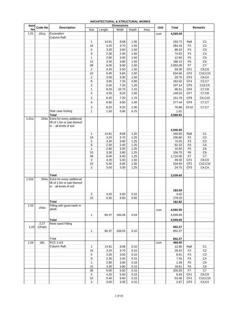
Nos Length Width Depth Area1.01 251a Excavation cum 4,569.00
Column Raft1 14.81 8.68 1.50 192.72 Raft C116 3.20 3.70 1.50 284.16 F2 C25 3.30 3.60 1.50 89.10 F3 C39 2.30 2.40 1.50 74.52 F4 C41 2.80 3.00 1.50 12.60 F5 C510 3.30 3.80 1.50 188.10 F6 C638 6.00 6.00 1.50 2,052.00 F7 C72 4.20 5.50 1.50 69.30 CF1 C9,C910 5.40 6.60 1.50 534.60 CF2 C10,C102 3.00 3.30 1.50 29.70 CF3 C4,C48 3.95 7.20 0.80 28.14 182.02 CF4 C2,C72 6.20 7.20 1.20 36.52 107.14 CF5 C10,C51 8.20 10.70 1.10 87.74 96.51 CF6 C7,C84 4.55 8.20 1.00 44.94 149.24 CF7 C7,C82 6.20 7.20 1.70 55.44 151.78 CF8 C5,C106 6.80 6.80 1.00 277.44 CF9 C7,C7
2 6.20 6.20 1.00 76.88 CF10 C7,C7Stair case footing 1 1.50 0.90 0.75 1.01 Total 4,568.81
1.01a 254a Extra for every additional lift of 1.5m or part thereof in - all kinds of soil
3,040.00 1 14.81 8.68 1.25 160.60 Raft C116 3.20 3.70 1.25 236.80 F2 C25 3.30 3.60 1.25 74.25 F3 C39 2.30 2.40 1.25 62.10 F4 C41 2.80 3.00 1.25 10.50 F5 C510 3.30 3.80 1.25 156.75 F6 C638 6.00 6.00 1.25 1,710.00 F7 C72 4.20 5.50 1.50 69.30 CF1 C9,C910 5.40 6.60 1.50 534.60 CF2 C10,C102 3.00 3.30 1.25 24.75 CF3 C4,C4
Total 3,039.65 1.01b 254a Extra for every additional
lift of 1.5m or part thereof in - all kinds of soil
183.00 2 4.20 5.50 0.10 4.62 10 5.40 6.60 0.50 178.20
Total 182.82 1.02
255aFilling with good earth in plinth cum 4,560.00
1 80.37 106.05 0.54 4,559.65
Total 4,559.65
1.032.27
CPWDRiver sand Filling
852.27 1 80.37 106.05 0.10 852.27
Total 852.27 1.04 281 PCC 1:4:8 cum 469.00
Column Raft 1 14.81 8.68 0.10 12.85 Raft C116 3.20 3.70 0.15 28.42 F2 C25 3.30 3.60 0.15 8.91 F3 C39 2.30 2.40 0.15 7.45 F4 C41 2.80 3.00 0.15 1.26 F5 C510 3.30 3.80 0.15 18.81 F6 C638 6.00 6.00 0.15 205.20 F7 C72 4.20 5.50 0.15 6.93 CF1 C9,C910 5.40 6.60 0.15 53.46 CF2 C10,C102 3.00 3.30 0.15 2.97 CF3 C4,C4
ARCHITECTURAL & STRUCTURAL WORKSItem
No DescriptionDimensions
Unit Total RemarksCode No.
1 of 15
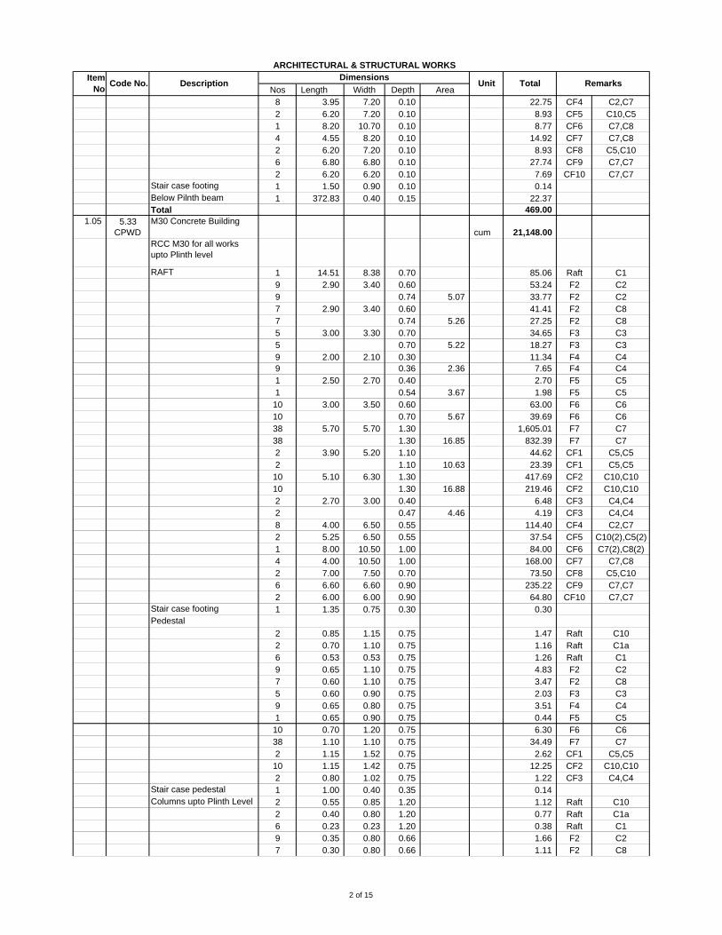
Nos Length Width Depth Area
ARCHITECTURAL & STRUCTURAL WORKSItem
No DescriptionDimensions
Unit Total RemarksCode No.
8 3.95 7.20 0.10 28.14 22.75 CF4 C2,C72 6.20 7.20 0.10 36.52 8.93 CF5 C10,C51 8.20 10.70 0.10 87.74 8.77 CF6 C7,C84 4.55 8.20 0.10 44.94 14.92 CF7 C7,C82 6.20 7.20 0.10 55.44 8.93 CF8 C5,C106 6.80 6.80 0.10 27.74 CF9 C7,C72 6.20 6.20 0.10 7.69 CF10 C7,C7
Stair case footing 1 1.50 0.90 0.10 0.14 Below Pilnth beam 1 372.83 0.40 0.15 22.37 Total 469.00
1.05 5.33 CPWD
M30 Concrete Buildingcum 21,148.00
RCC M30 for all works upto Plinth level
RAFT 1 14.51 8.38 0.70 85.06 Raft C19 2.90 3.40 0.60 53.24 F2 C29 0.74 5.07 33.77 F2 C27 2.90 3.40 0.60 41.41 F2 C87 0.74 5.26 27.25 F2 C85 3.00 3.30 0.70 34.65 F3 C35 0.70 5.22 18.27 F3 C39 2.00 2.10 0.30 11.34 F4 C49 0.36 2.36 7.65 F4 C41 2.50 2.70 0.40 2.70 F5 C51 0.54 3.67 1.98 F5 C510 3.00 3.50 0.60 63.00 F6 C610 0.70 5.67 39.69 F6 C638 5.70 5.70 1.30 1,605.01 F7 C738 1.30 16.85 832.39 F7 C72 3.90 5.20 1.10 44.62 CF1 C5,C52 1.10 10.63 23.39 CF1 C5,C510 5.10 6.30 1.30 417.69 CF2 C10,C1010 1.30 16.88 219.46 CF2 C10,C102 2.70 3.00 0.40 6.48 CF3 C4,C42 0.47 4.46 4.19 CF3 C4,C48 4.00 6.50 0.55 26.00 114.40 CF4 C2,C72 5.25 6.50 0.55 34.13 37.54 CF5 C10(2),C5(2)1 8.00 10.50 1.00 84.00 84.00 CF6 C7(2),C8(2)4 4.00 10.50 1.00 42.00 168.00 CF7 C7,C82 7.00 7.50 0.70 52.50 73.50 CF8 C5,C106 6.60 6.60 0.90 235.22 CF9 C7,C72 6.00 6.00 0.90 64.80 CF10 C7,C7
Stair case footing 1 1.35 0.75 0.30 0.30 Pedestal
2 0.85 1.15 0.75 1.47 Raft C102 0.70 1.10 0.75 1.16 Raft C1a6 0.53 0.53 0.75 1.26 Raft C19 0.65 1.10 0.75 4.83 F2 C27 0.60 1.10 0.75 3.47 F2 C85 0.60 0.90 0.75 2.03 F3 C39 0.65 0.80 0.75 3.51 F4 C41 0.65 0.90 0.75 0.44 F5 C510 0.70 1.20 0.75 6.30 F6 C638 1.10 1.10 0.75 34.49 F7 C72 1.15 1.52 0.75 2.62 CF1 C5,C510 1.15 1.42 0.75 12.25 CF2 C10,C102 0.80 1.02 0.75 1.22 CF3 C4,C4
Stair case pedestal 1 1.00 0.40 0.35 0.14 Columns upto Plinth Level 2 0.55 0.85 1.20 1.12 Raft C10
2 0.40 0.80 1.20 0.77 Raft C1a6 0.23 0.23 1.20 0.38 Raft C19 0.35 0.80 0.66 1.66 F2 C27 0.30 0.80 0.66 1.11 F2 C8
2 of 15

Nos Length Width Depth Area
ARCHITECTURAL & STRUCTURAL WORKSItem
No DescriptionDimensions
Unit Total RemarksCode No.
5 0.30 0.60 0.60 0.54 F3 C39 0.35 0.50 1.34 2.11 F4 C41 0.35 0.60 1.06 0.22 F5 C510 0.40 0.90 0.70 2.52 F6 C638 0.80 0.80 - - F7 C74 0.35 0.60 0.15 0.13 CF1 C5,C520 0.55 0.85 0.55 5.14 CF2 C10,C104 0.35 0.50 1.03 0.72 CF3 C4,C48 0.35 0.80 0.15 0.34 CF4 C28 0.80 0.80 0.15 0.77 CF4 C74 0.35 0.60 0.15 0.13 CF5 C5(2)4 0.55 0.85 0.15 0.28 CF5 C10(2)2 0.80 0.80 0.15 0.19 CF6 C7(2)2 0.30 0.80 0.15 0.07 CF6 C8(2)4 0.80 0.80 0.15 0.38 CF7 C74 0.30 0.80 0.15 0.14 CF7 C84 0.35 0.60 0.15 0.13 CF8 C54 0.55 0.85 0.15 0.28 CF8 C1012 0.80 0.80 0.15 1.15 CF9 C7,C74 0.30 0.80 0.15 0.14 CF10 C7,C7
Plinth Beam 2 80.60 0.25 0.60 24.18 PB112 80.60 0.25 0.60 145.07 PB112 106.05 0.25 0.60 190.89 PB1
Raft Beam 2 14.51 0.70 0.15 3.05 RFB12 8.38 0.40 0.15 1.01 RFB21 8.38 0.23 0.15 0.29 RFB3
Total 4,812.00 above basement upto 5th Floor hieghtFor Walls, columns, pillars,posts and struts.Column G.F 7 0.23 0.23 2.80 1.04 C1
2 0.40 0.80 2.80 1.79 C1a17 0.35 0.80 2.80 13.33 C25 0.30 0.60 2.80 2.52 C313 0.35 0.50 2.80 6.37 C413 0.35 0.60 2.80 7.64 C510 0.40 0.90 2.80 10.08 C668 0.80 0.80 2.80 121.86 C713 0.30 0.80 2.80 8.74 C832 0.55 0.85 2.80 41.89 C10
First Floor 7 0.23 0.23 2.80 1.04 C12 0.40 0.80 2.80 1.79 C1a17 0.35 0.80 2.80 13.33 C25 0.30 0.60 2.80 2.52 C313 0.35 0.50 2.80 6.37 C413 0.35 0.60 2.80 7.64 C510 0.40 0.90 2.80 10.08 C668 0.80 0.80 2.80 121.86 C713 0.30 0.80 2.80 8.74 C832 0.55 0.85 2.80 41.89 C10
Second Floor 7 0.23 0.23 2.80 1.04 C12 0.40 0.80 2.80 1.79 C1a17 0.35 0.80 2.80 13.33 C25 0.30 0.60 2.80 2.52 C313 0.35 0.50 2.80 6.37 C413 0.35 0.60 2.80 7.64 C510 0.40 0.90 2.80 10.08 C668 0.80 0.80 2.80 121.86 C713 0.30 0.80 2.80 8.74 C832 0.55 0.85 2.80 41.89 C10
3 of 15
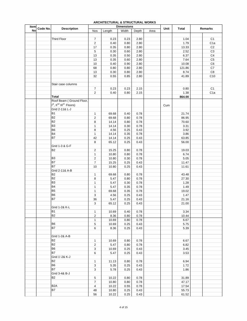
Nos Length Width Depth Area
ARCHITECTURAL & STRUCTURAL WORKSItem
No DescriptionDimensions
Unit Total RemarksCode No.
Third Floor 7 0.23 0.23 2.80 1.04 C12 0.40 0.80 2.80 1.79 C1a17 0.35 0.80 2.80 13.33 C25 0.30 0.60 2.80 2.52 C313 0.35 0.50 2.80 6.37 C413 0.35 0.60 2.80 7.64 C510 0.40 0.90 2.80 10.08 C668 0.80 0.80 2.80 121.86 C713 0.30 0.80 2.80 8.74 C832 0.55 0.85 2.80 41.89 C10
Stair case columns7 0.23 0.23 2.15 0.80 C12 0.40 0.80 2.15 1.38 C1a
Total 864.00 Roof Beam ( Ground Floor, Ist, IInd IIIrd Floors) CumGrid 2-11& L-JB1 1 69.68 0.40 0.78 21.74 B2 2 69.68 0.80 0.78 86.95 B2 8 14.14 0.80 0.78 70.60 B3 1 14.14 0.30 0.78 3.31 B6 8 4.56 0.25 0.43 3.92 B4 1 14.14 0.35 0.78 3.86 B7 42 14.14 0.25 0.43 63.85
8 65.12 0.25 0.43 56.00 Grid 1-3 & G-FB2 2 15.25 0.80 0.78 19.03
1 10.80 0.80 0.78 6.74 B3 2 10.80 0.30 0.78 5.05 B7 7 15.25 0.25 0.43 11.47 B7 10 10.80 0.25 0.43 11.61 Grid 2-11& A-BB2 1 69.68 0.80 0.78 43.48 B2 8 5.47 0.80 0.78 27.30 B3 1 5.47 0.30 0.78 1.28 B4 1 5.47 0.35 0.78 1.49 B5 1 69.68 0.35 0.78 19.02 B6 3 4.56 0.25 0.43 1.47 B7 36 5.47 0.25 0.43 21.16
3 65.12 0.25 0.43 21.00 Grid 1-2& K-LB1 1 10.69 0.40 0.78 3.34 B2 2 8.36 0.80 0.78 10.44
1 10.69 0.80 0.78 6.67 B6 5 10.69 0.25 0.43 5.75 B7 6 8.36 0.25 0.43 5.39
Grid 1-2& A-BB2 1 10.69 0.80 0.78 6.67 B2 2 5.47 0.80 0.78 6.82 B6 3 10.69 0.25 0.43 3.45 B7 6 5.47 0.25 0.43 3.53 Grid 1'-2& K-JB2 1 11.13 0.80 0.78 6.94 B6 3 5.35 0.25 0.43 1.72 B7 3 5.78 0.25 0.43 1.86 Grid 3-4& B-JB2 5 10.22 0.80 0.78 31.89
7 10.80 0.80 0.78 47.17 B2A 4 10.22 0.55 0.78 17.54 B7 48 10.80 0.25 0.43 55.73
56 10.22 0.25 0.43 61.52
4 of 15

Nos Length Width Depth Area
ARCHITECTURAL & STRUCTURAL WORKSItem
No DescriptionDimensions
Unit Total RemarksCode No.
Grid 1'-3& G-J,B-FB2 3 9.90 0.80 0.78 18.53
7 10.80 0.80 0.78 47.17 B2A 4 9.90 0.55 0.78 16.99 B7 49 9.90 0.25 0.43 52.15
49 10.80 0.25 0.43 56.89 B3 7 10.80 0.30 0.78 17.69 Grid 10-11& B-JB2 8 10.80 0.80 0.78 53.91
5 4.48 0.80 0.78 13.98 B2A 4 4.48 0.55 0.78 7.69 B7 16 10.80 0.25 0.43 18.58
56 4.48 0.25 0.43 26.97 B4 8 10.80 0.35 0.78 23.59 For Span 10.8x8.4B2 24 8.40 0.80 0.78 125.80 B2 48 10.80 0.80 0.78 323.48
24 8.40 0.80 0.78 125.80 B7 168 8.40 0.25 0.43 151.70
120 10.80 0.25 0.43 139.32
For Span 10.8x8.4B2 24 8.40 0.80 0.78 125.80 B2 48 10.80 0.80 0.78 323.48 B2A 24 8.40 0.55 0.78 86.49 B7 168 8.40 0.25 0.43 151.70
120 10.80 0.25 0.43 139.32 Lift Room BeamMRB1 4 1.77 0.23 0.30 0.49 MRB2 1 8.41 0.23 0.45 0.87 MRB3 1 3.83 0.23 0.40 0.35 MRB4 1 8.41 0.30 0.80 2.02 Total 2,827.52 For lift room upper roof beam (2.5m above IIIrd floor)LRB1 1 43.21 0.23 0.23 2.24 For ramp portion Entry ramp (To I- Floor , RB1 4 5.35 0.30 0.35 2.24 RB2 6 5.35 0.30 0.25 2.41 RB4 1 32.83 0.30 0.45 4.43 RB3 1 32.83 0.30 0.70 6.89 Exit ramp (from I- Floor , RB1 7 5.35 0.30 0.35 3.93 RB2 5 5.35 0.30 0.25 2.00 RB3 1 43.15 0.30 0.70 9.06 RB4 1 43.15 0.30 0.45 5.83 Entry ramp (To II- Floor , RB1 5 5.35 0.30 0.35 2.81 RB2 4 5.35 0.30 0.25 1.60 RB3 1 32.42 0.30 0.70 6.81 RB4 1 32.42 0.30 0.45 4.38 Exit ramp (from II- Floor , RB1 6 5.35 0.30 0.35 3.37 RB2 4 5.35 0.30 0.25 1.60 RB3 1 37.34 0.30 0.70 7.84 RB4 1 37.34 0.30 0.45 5.04 Entry ramp (To III- Floor , RB1 5 5.35 0.30 0.35 2.81 RB2 4 5.35 0.30 0.25 1.60 RB3 1 32.42 0.30 0.70 6.81 RB4 1 32.42 0.30 0.45 4.38 Exit ramp (from III- Floor ,
5 of 15

Nos Length Width Depth Area
ARCHITECTURAL & STRUCTURAL WORKSItem
No DescriptionDimensions
Unit Total RemarksCode No.
RB1 6 5.35 0.30 0.35 3.37 RB2 4 5.35 0.30 0.25 1.60 RB3 1 37.34 0.30 0.70 7.84 RB4 1 37.34 0.30 0.45 5.04 Stair case beamSB1 9 1.70 0.25 0.15 0.57
5 1.00 0.25 0.15 0.19 Steps 54 1.70 0.02 1.72
18 1.00 0.02 0.34
Total For Three Floors 11,419.00
Roof Slab ( Ground Floor, Ist, IInd IIIrd Floors)
1 75.02 106.05 0.12 954.70 1 5.35 8.36 0.12 5.36 1 5.35 10.81 0.12 6.93 1 5.35 11.33 0.12 7.27
deduction for lift room 1 8.41 3.60 0.12 (3.63) Total 970.64 deduction for ground slab
1 5.35 41.32 0.12 (26.50) for lift room III rd floor 1 3.70 1.77 0.12 0.79 For lift room upper roof 1 8.41 3.60 0.12 3.63 For ramp SlabEntry ramp (To I- Floor , Grid 1'-2& G'-K 1 38.44 5.35 0.15 30.82 Exit ramp (from I- Floor , Grid 1-1'& B'-G 1 43.53 5.35 0.15 34.90 Entry ramp (To II- Floor , Grid 1-2 & G-L)Grid 1-1' & K-G' 1 38.35 5.35 0.15 30.75 Exit ramp (from II- Floor , Grid 1-1'& A-G)Grid 1-1'& B'-E" 1 32.49 5.35 0.15 26.05 Entry ramp (To III- Floor , Grid 1-2 & G-L)Grid 1-1' & K-G' 1 38.35 5.35 0.15 30.75 Exit ramp (from III- Floor , Grid 1-1'& A-G)Grid 1-1'& B'-E" 1 38.35 5.35 0.15 30.75 Stair case Slab 1 26.50 1.50 0.15 5.96 Landing Slab 9 1.70 1.00 0.15 2.30 Total For Three Floors 4,053.00
1.05a5.34.1 CPWD
Add or deduct for providing richer or leaner mixes
21,148.00
1.06 504 HYSD Steel MT 3,984.61
Footing 50.00 kg/cum 142.89 Combined footing 100.00 kg/cum 149.33 Raft Footing 200.00 kg/cum 17.01 Column upto 1st FloorStair pedestal 165.00 kg/cum 0.02 51.29 C1 315.00 kg/cum 0.84 86.46 C2 188.00 kg/cum 3.79 C1a 165.00 kg/cum 0.61 C3 284.00 kg/cum 1.44 C4 291.00 kg/cum 3.70 C5 208.00 kg/cum 2.35
6 of 15

Nos Length Width Depth Area
ARCHITECTURAL & STRUCTURAL WORKSItem
No DescriptionDimensions
Unit Total RemarksCode No.
C6 140.00 kg/cum 2.65 C7 342.00 kg/cum 54.37 C8 218.00 kg/cum 2.95 C10 220.00 kg/cum 13.73
1st floor & IInd floor 71.03 C1 315.00 kg/cum 0.65 122.99 C2 188.00 kg/cum 5.01 C1a 165.00 kg/cum 0.59 C3 284.00 kg/cum 1.43 C4 291.00 kg/cum 3.71 C5 208.00 kg/cum 3.18 C6 140.00 kg/cum 2.82 C7 342.00 kg/cum 83.35 C8 218.00 kg/cum 3.81 C10 220.00 kg/cum 18.43
IIIrd Floor 36.53 C1 315.00 kg/cum 0.58 61.97 C2 188.00 kg/cum 2.51 C1a 165.00 kg/cum 0.52 C3 284.00 kg/cum 0.72 C4 291.00 kg/cum 1.85 C5 208.00 kg/cum 1.59 C6 140.00 kg/cum 1.41 C7 342.00 kg/cum 41.67 C8 218.00 kg/cum 1.90 C10 220.00 kg/cum 9.22
Plinth Beam PB1 210.00 kg/cum 75.63 45.02 75.63
Roof Beam B1 245.00 kg/cum 24.57 1,424.86 B2 200.00 kg/cum 1,217.53 2,449.68 B2A 235.00 kg/cum 120.98 B3 240.00 kg/cum 26.24 B4 215.00 kg/cum 24.89 B5 215.00 kg/cum 16.36 B6 186.00 kg/cum 12.13 B7 235.00 kg/cum 986.78
Ramp Beam
RB1 205.00 kg/cum 3.80 RB2 245.00 kg/cum 2.65 RB3 185.00 kg/cum 8.37 RB4 185.00 kg/cum 5.38
Raft Beam 1,500.00 kg/cum 6.51
Lift roof beams
MRB1 215.00 kg/cum 2.34 MRB2 185.00 kg/cum 0.64 MRB3 180.00 kg/cum 0.25 MRB4 180.00 kg/cum 1.45
stair case beams 245.00 kg/cum 0.69
Slab 200.00 kg/cum 810.60 RCC Parapet wall 130.00 kg/cum 56.16
Total 3,984.61
1.07 Brick work
7 of 15

Nos Length Width Depth Area
ARCHITECTURAL & STRUCTURAL WORKSItem
No DescriptionDimensions
Unit Total RemarksCode No.
1.07a303
Ground Floorcum 321.00
2 80.37 0.20 2.80 90.01 2 106.05 0.20 2.80 118.78
Parapet wall on terrace 2 80.37 0.20 1.50 48.22 2 106.05 0.20 1.50 63.63
Total 321.00 1.07b 310 Extra for brick work above
plinth upto floor five level321.00
Qty as the BW of all works upto plinth level 321.00 Total 321.00
1.08 13.7.2 CPWD
Plastering with CM 1:4 mix (one cement and 4 sand) 12mm thick For outside walls Sqm 1,604.00 Ground Floor 2 80.37 2.80 450.04
2 106.05 2.80 593.88 Parapet wall on terrace 2 80.37 1.50 241.10
2 106.05 1.50 318.15 Total 1,604.00
1.09 13.8.2 Plastering with CM 1:4 mix Sqm 1,604.00 Ground Floor
2 80.37 2.80 450.04 2 106.05 2.80 593.88
Parapet wall on terrace 2 80.37 1.50 241.10 2 106.05 1.50 318.15
Total 1,604.00
8 of 15

Nos Length Width Depth Area
ARCHITECTURAL & STRUCTURAL WORKSItem
No DescriptionDimensions
Unit Total RemarksCode No.
1.10 13.16 CPWD
1:3 Plastering for CeilingSqm 32,134.00
Roof Slab ( Ground Floor, Ist, IInd IIIrd Floors)
1 75.02 106.05 7,955.87 1 5.35 8.36 44.69 1 5.35 10.81 57.78 1 5.35 11.33 60.55
deduction for lift room 1 8.41 3.60 (30.23) Total 8,088.66 deduction for ground slab on grid 1'-2 & G'-L 1 5.35 41.32 (220.87) for three floors 32,134.00
1.11 13.48.1 CPWD
Two coats of exterior type emulsion paint 68,256.00 Ground Floor
2 80.37 3.60 578.63 2 106.05 3.60 763.56
First Floor 2 80.37 1.00 160.73 2 106.05 1.00 212.10
Second Floor 2 80.37 1.00 160.73 2 106.05 1.00 212.10
Third Floor 2 80.37 1.00 160.73 2 106.05 1.00 212.10
Parapet wall on terrace 2 80.37 1.50 241.10 2 106.05 1.50 318.15
Total 3,020.00 Providing With Distemper on interior walls
Ground Floor 2 80.37 2.80 450.04 2 106.05 2.80 593.88 4 32.83 1.00 131.30 4 42.63 1.00 170.50
First Floor 2 80.37 1.00 160.73 2 106.05 1.00 212.10 2 72.99 1.00 145.97 2 93.79 1.00 187.58 4 32.68 1.00 130.72 4 32.24 1.00 128.96
Second Floor2 80.37 1.00 160.73 2 106.05 1.00 212.10 2 72.99 1.00 145.97 2 93.79 1.00 187.58 4 32.68 1.00 130.72 4 32.24 1.00 128.96
Third Floor2 80.37 1.00 160.73 2 106.05 1.00 212.10 2 32.68 1.00 65.36 2 32.24 1.00 64.48 4 80.37 1.50 482.19 4 106.05 1.50 636.30
Parapet wall on terrace 2 80.37 1.50 241.10 2 106.05 1.50 318.15
For beams & ColumnsColumnsColumn G.F 7 0.92 2.80 18.03
2 2.40 2.80 13.44 17 2.30 2.80 109.48 5 1.80 2.80 25.20 13 1.70 2.80 61.88 13 1.90 2.80 69.16
9 of 15

Nos Length Width Depth Area
ARCHITECTURAL & STRUCTURAL WORKSItem
No DescriptionDimensions
Unit Total RemarksCode No.
10 2.60 2.80 72.80 68 3.20 2.80 609.28 13 2.20 2.80 80.08 32 2.80 2.80 250.88
First Floor 7 0.92 2.80 18.03 2 2.40 2.80 13.44 17 2.30 2.80 109.48 5 1.80 2.80 25.20 13 1.70 2.80 61.88 13 1.90 2.80 69.16 10 2.60 2.80 72.80 68 3.20 2.80 609.28 13 2.20 2.80 80.08 32 2.80 2.80 250.88
Second Floor 7 0.92 2.80 18.03 2 2.40 2.80 13.44 17 2.30 2.80 109.48 5 1.80 2.80 25.20 13 1.70 2.80 61.88 13 1.90 2.80 69.16 10 2.60 2.80 72.80 68 3.20 2.80 609.28 13 2.20 2.80 80.08 32 2.80 2.80 250.88
Third Floor 7 0.92 2.80 18.03 2 2.40 2.80 13.44 17 2.30 2.80 109.48 5 1.80 2.80 25.20 13 1.70 2.80 61.88 13 1.90 2.80 69.16 10 2.60 2.80 72.80 68 3.20 2.80 609.28 13 2.20 2.80 80.08 32 2.80 2.80 250.88
Stair case columns 7 0.92 2.15 13.85 2 2.40 2.15 10.32
BeamsB1 4 80.37 1.56 501.48 B2 4 2,248.16 1.56 14,028.52 B2A 4 300.00 1.56 1,872.00 B3 4 116.81 1.56 728.89 B4 4 106.01 1.56 661.50 B5 4 69.68 1.56 434.77 B6 4 151.66 0.86 521.71 B7 4 9,765.27 0.86 33,592.52 Ramp BeamsRB1 1 176.39 0.70 123.47 RB2 1 144.32 0.50 72.16 RB3 1 215.50 1.40 301.70 RB4 1 215.50 0.90 193.95 Stair case beamSB1 1 20.30 0.30 6.09 Steps 1 109.80 0.40 43.92 Lift Room BeamMRB1 4 7.08 0.60 16.99 MRB2 4 8.41 0.90 30.28 MRB3 4 3.83 0.80 12.26 MRB4 4 8.41 1.60 53.82 For lift room upper roof beam (2.5m above IIIrd floor)LRB1 1 43.21 0.45 19.44 Ramp Slab
1 38.44 5.35 205.46 1 43.53 5.35 232.69 1 38.35 5.35 204.98 1 32.49 5.35 173.66 1 38.35 5.35 204.98
10 of 15

Nos Length Width Depth Area
ARCHITECTURAL & STRUCTURAL WORKSItem
No DescriptionDimensions
Unit Total RemarksCode No.
1 38.35 5.35 204.98 Stair case Slab 1 26.50 1.50 39.75 Landing Slab 18 1.70 1.00 30.60 Total 65,236.00
1.12 13.37.1 CPWD
Two coats of cement paint(white) for ceiling Sqm 32,134.00
32,134.00 Total 32,134.00
1.1311.9.5 CPWD
40mm thick marble chip flooring 8,566.00
1 80.60 106.28 8,565.64
PCC 1:2:4 Flooring Cum 821.00 1 80.60 106.28 0.10 856.56
Deduction for plinth Beams
2 80.60 0.25 0.10 (4.03) 12 106.05 0.25 0.10 (31.82)
Total 821.00 Chequers of approved pattern on floors Sqm 8,207.00
1 80.60 106.28 8,565.64
2 80.60 0.25 (40.30) 12 106.05 0.25 (318.15)
Total 8,207.00 1.14
16.64 CPWD
40 mm brick Aggregates below 1:2:4 pcc Flooring
Sqm 8,208.00 1 80.60 106.28 8,565.64
- 2 80.60 0.25 (40.30) 12 106.05 0.25 (318.15)
Total 8,208.00
1.1512.15
CPWD Painting with bitumen on terrace Sqm 8,480.00
1 80.14 105.82 8,479.89 Total 8,480.00
1.165.9.13 CPWD
Shuttering of parapet wall4,333.00
Entry ramp parapet 4 32.83 1.00 131.30 Exit ramp parapet 4 42.63 1.00 170.50 First Floor 4 80.37 1.00 321.46
4 106.05 1.00 424.20 2 72.99 1.00 145.97 2 93.79 1.00 187.58 4 32.68 1.00 130.72 4 32.24 1.00 128.96
Second Floor - 4 80.37 1.00 321.46 4 106.05 1.00 424.20 2 72.99 1.00 145.97 2 93.79 1.00 187.58 4 32.68 1.00 130.72 4 32.24 1.00 128.96
Third Floor - 4 80.37 1.00 321.46 4 106.05 1.00 424.20 2 72.99 1.00 145.97 2 93.79 1.00 187.58 4 32.68 1.00 130.72 4 32.24 1.00 128.96 4 0.20 1.00 0.80
Deduction for plinth Beams
11 of 15

Nos Length Width Depth Area
ARCHITECTURAL & STRUCTURAL WORKSItem
No DescriptionDimensions
Unit Total RemarksCode No.
4 0.20 1.00 0.80 4 0.20 1.00 0.80 4 0.20 1.00 0.80 2 0.20 1.00 0.40 2 0.20 1.00 0.40 4 0.20 1.00 0.80 4 0.20 1.00 0.80 4 0.20 1.00 0.80 4 0.20 1.00 0.80 2 0.20 1.00 0.40 2 0.20 1.00 0.40 4 0.20 1.00 0.80 4 0.20 1.00 0.80 4 0.20 1.00 0.80 4 0.20 1.00 0.80 2 0.20 1.00 0.40 2 0.20 1.00 0.40 4 0.20 1.00 0.80 4 0.20 1.00 0.80
Total 4,333.00
1.175.8
CPWD Parapet Wall RCC M30 432.00 Entry ramp parapet 2 32.83 0.20 1.00 13.13 Exit ramp parapet 2 42.63 0.20 1.00 17.05
First Floor - 2 80.37 0.20 1.00 32.15 2 106.05 0.20 1.00 42.42 1 72.99 0.20 1.00 14.60 1 93.79 0.20 1.00 18.76
Entry ramp parapet 2 32.68 0.20 1.00 13.07 Exit ramp parapet 2 32.24 0.20 1.00 12.90 Second Floor -
2 80.37 0.20 1.00 32.15 2 106.05 0.20 1.00 42.42 1 72.99 0.20 1.00 14.60 1 93.79 0.20 1.00 18.76
Entry ramp parapet 2 32.68 0.20 1.00 13.07 Exit ramp parapet 2 32.24 0.20 1.00 12.90 Third Floor
2 80.37 0.20 1.00 32.15 2 106.05 0.20 1.00 42.42 1 72.99 0.20 1.00 14.60 1 93.79 0.20 1.00 18.76
Entry ramp parapet 2 32.68 0.20 1.00 13.07 Exit ramp parapet 2 32.24 0.20 1.00 12.90
432.00
12 of 15

Nos Length Width Depth Area
ARCHITECTURAL & STRUCTURAL WORKSItem
No DescriptionDimensions
Unit Total RemarksCode No.
Shuttering Works
1.195.9.1
CPWD For Foundation
4,063.00 RAFT FOUNDATION
1 45.77 0.70 32.04 9 12.60 1.34 151.96 7 12.60 1.34 118.19 5 12.60 1.40 88.20 9 8.20 0.66 48.71 1 10.40 0.94 9.78 10 13.00 1.30 169.00 38 22.80 2.60 2,252.64 2 18.20 2.20 80.08 10 22.80 2.60 592.80 2 11.40 0.87 19.84 8 21.00 0.55 92.40 2 23.50 0.55 25.85 1 37.00 1.00 37.00 4 29.00 1.00 116.00 2 29.00 0.70 40.60 6 26.40 0.90 142.56 2 24.00 0.90 43.20 1 4.20 0.30 1.26
Total 4,063.00
1.205.9.6
CPWD For Columns & struts
5,714.00 2 4.00 0.75 6.00 2 3.60 0.75 5.40 6 2.12 0.75 9.54 9 3.50 0.75 23.63 7 3.40 0.75 17.85 5 3.00 0.75 11.25 9 2.90 0.75 19.58 1 3.10 0.75 2.33 10 3.80 0.75 28.50 38 4.40 0.75 125.40 2 5.34 0.75 8.01 10 5.14 0.75 38.55 2 3.64 0.75 5.46 1 2.80 0.35 0.98 2 2.80 1.20 6.72 2 2.40 1.20 5.76 9 2.30 0.66 13.66 7 2.20 0.66 10.16 5 1.80 0.60 5.40 9 1.70 1.34 20.50 1 1.90 1.06 2.01 10 2.60 0.70 18.20 4 1.90 0.15 1.14 20 2.80 0.55 30.80 4 1.70 1.03 7.00 8 2.30 0.15 2.76 8 3.20 0.15 3.84 4 1.90 0.15 1.14 4 2.80 0.15 1.68 2 3.20 0.15 0.96 2 2.20 0.15 0.66 4 3.20 0.15 1.92 4 2.20 0.15 1.32 4 1.90 0.15 1.14 4 2.80 0.15 1.68 12 3.20 0.15 5.76 4 2.20 0.15 1.32
13 of 15

Nos Length Width Depth Area
ARCHITECTURAL & STRUCTURAL WORKSItem
No DescriptionDimensions
Unit Total RemarksCode No.
Column G.F 7 0.92 2.80 18.03 2 2.40 2.80 13.44 17 2.30 2.80 109.48 5 1.80 2.80 25.20 13 1.70 2.80 61.88 13 1.90 2.80 69.16 10 2.60 2.80 72.80 68 3.20 2.80 609.28 13 2.20 2.80 80.08 32 2.80 2.80 250.88
First Floor - - - 7 0.92 2.80 18.03 2 2.40 2.80 13.44 17 2.30 2.80 109.48 5 1.80 2.80 25.20 13 1.70 2.80 61.88 13 1.90 2.80 69.16 10 2.60 2.80 72.80 68 3.20 2.80 609.28 13 2.20 2.80 80.08 32 2.80 2.80 250.88
Second Floor 7 0.92 2.80 18.03 2 2.40 2.80 13.44 17 2.30 2.80 109.48 5 1.80 2.80 25.20 13 1.70 2.80 61.88 13 1.90 2.80 69.16 10 2.60 2.80 72.80 68 3.20 2.80 609.28 13 2.20 2.80 80.08 32 2.80 2.80 250.88
Third Floor7 0.92 2.80 18.03 2 2.40 2.80 13.44 17 2.30 2.80 109.48 5 1.80 2.80 25.20 13 1.70 2.80 61.88 13 1.90 2.80 69.16 10 2.60 2.80 72.80 68 3.20 2.80 609.28 13 2.20 2.80 80.08 32 2.80 2.80 250.88
Stair case columns - -
7 0.92 2.15 13.85 2 2.40 2.15 10.32
Total 5,714.00
1.215.9.3
CPWD For Slabs
32,367.00 1 75.02 106.05 7,955.87 1 5.35 8.36 44.69 1 5.35 10.81 57.78 1 5.35 11.33 60.55 1 362.14 0.12 43.46
deduction for lift room 1 8.41 3.60 (30.23) Total 8,132.12 deduction for ground slab on grid 1'-2 & G'-L 1 5.35 41.32 (220.87)
1 3.70 1.77 6.55 1 8.41 3.60 30.23
Landing Slab 9 1.70 1.00 15.30 9 5.40 0.15 7.29
32,367.00
1.225.9.5
CPWD For Beams
52,948.00 B1 1 80.37 1.96 157.52 B2 1 2,248.16 2.36 5,305.66 B3 1 116.81 1.86 217.27
14 of 15

Nos Length Width Depth Area
ARCHITECTURAL & STRUCTURAL WORKSItem
No DescriptionDimensions
Unit Total RemarksCode No.
B4 1 106.01 1.91 202.48 B5 1 69.68 1.91 133.08 B6 1 151.66 1.11 168.34 B7 1 9,765.27 1.11 10,839.45 MRB1 1 7.08 0.83 5.88 MRB2 1 8.41 1.13 9.50 MRB3 1 3.83 1.03 3.94 MRB4 1 8.41 1.90 15.98 Total 17,059.09 LRB1 1 43.21 0.68 29.38 Plinth Beam 1 1,433.79 1.20 1,720.55
28 0.25 0.60 4.20 Raft beam 2 14.51 0.30 8.71
2 8.38 0.30 5.03 1 8.38 0.30 2.51
Total for three floors 52,948.00
1.235.9.7
CPWD For ramp Slab 1,394.00 1 38.44 5.35 205.46 1 43.53 5.35 232.69 1 38.35 5.35 204.98 1 32.49 5.35 173.66 1 38.35 5.35 204.98 1 38.35 5.35 204.98 2 229.51 0.20 91.80
Stair case 1 26.50 1.50 39.75 1 53.00 0.15 7.95
SB1 1 20.30 0.55 11.17 Steps 72 1.50 0.15 16.20 Total 1,394.00
1.24 5.27 CPWD Expansion Joint per cm
depth 15.43
total length for three floors 2 80.37 per cm 642.92 Total width 15.43
per 100m
1.255.29.1.1 CPWD Sheet covering 642.92
2 80.37 642.92
1.2616.59.2 CPWD Sign boards Sqm 14.04
10 0.35 14.04
15 of 15

#8, Second Floor, 80 Feet Road,
RT Nagar Bangalore Karnataka - 560 032. India
w +91.80. 3918.7500 f +91.80. 2363.4097
www.WilburSmith.com