ascjunior flender 2006 tradehousetradehouse.dk/pdf/hoistmanualeng.pdf · operating and s.r.l....
TRANSCRIPT
OPERATING AND
S.r.l. PONTEGGI AUTOSOLLEVANTI - Via S. Rocco, 8 - 31041 CORNUDA (TV) - ITALY
04-10
JUNIORBUILDERS HOIST
REV 002
Tel. ++39.423.639321 r.a. - Fax ++39.423.639410 - E-mail: [email protected] - http//www.safi.it
SERVICE MANUAL
“JUNIOR” BUILDER HOIST 04-10
1
TABLE OF CONTENTS
1.0 Guide to consultation ............................................................................................... 91.1 Assembly - Operation - Safety and maintenance .................................................................9
2.0 Technical specifications.......................................................................................... 112.1 Technical specifications .....................................................................................................11
3.0 Description .............................................................................................................. 133.1 General desription .............................................................................................................13
3.2 Overall dimensions .............................................................................................................14
4.0 Machine components.............................................................................................. 154.1 Base ....................................................................................................................................17
4.2 Base enclosure ...................................................................................................................18
4.3 Vertical and end elements ..................................................................................................19
4.4 Hoist cage with forks and guardrails ..................................................................................20
4.5 Cable basket .......................................................................................................................21
4.6 Electrical cable ..................................................................................................................23
4.7 Cable arm............................................................................................................................23
4.8 Cable guide.........................................................................................................................23
4.9 Anchoring ...........................................................................................................................24
4.10 Standard landing gate .........................................................................................................25
4.11 Optional for landig gate......................................................................................................26
4.12 Lifting unit..........................................................................................................................28
4.13 Fork.....................................................................................................................................29
4.14 Guide rollers .......................................................................................................................30
4.15 Centrifugal brake ................................................................................................................32
4.16 Electrical panel ...................................................................................................................33
5.0 Safety systems ......................................................................................................... 355.1 Description of safety system .............................................................................................36
6.0 Electrical system ..................................................................................................... 396.1 Wiring diagrams .................................................................................................................39
7.0 Safety precautions .................................................................................................. 457.1 General precautions ............................................................................................................45

“JUNIOR” BUILDER HOIST 04-10
2
8.0 Assembly ..................................................................................................................478.1 Reaction values.................................................................................................................. 53
9.0 Use ............................................................................................................................55
10.0 Dismantling..............................................................................................................57
11.0 Maintenance ............................................................................................................59
12.0 Self-braking unit .....................................................................................................6312.1 Components of the self-braking unit ................................................................................. 63
12.2 Adjusting the brake............................................................................................................ 64
12.3 Fitting the manual release.................................................................................................. 64
12.4 Replacing the brake disk.................................................................................................... 64
12.5 Maintenance....................................................................................................................... 65
13.0 Transport procedures.............................................................................................67
14.0 Emergency procedures ...........................................................................................69
15.0 Operating hints .......................................................................................................71
16.0 Troubleshooting ......................................................................................................73
17.0 General safety precautions.....................................................................................7517.1 Manual emergency descent................................................................................................ 75
18.0 Spare parts list ........................................................................................................7718.1 Mechanical part ................................................................................................................. 77
18.2 Electrical part..................................................................................................................... 79

“JUNIOR” BUILDER HOIST 04-10
3
Index
LIST OF FIGURES
Figura 3.2.1 Overall dimensions ............................................................................14
Figura 4.0.1 Assembly ............................................................................................16
Figura 4.1.1 Base ....................................................................................................17
Figura 4.2.1 Base enclosure ....................................................................................18
Figura 4.3.1 Vertical and end elements...................................................................19
Figura 4.4.1 Hoist cage with forks and guardrails ..................................................20
Figura 4.5.1 Cable basket........................................................................................21
Figura 4.5.1 Derivation box on the cable basket ....................................................22
Figura 4.8.1 Cable arm............................................................................................23
Figura 4.8.2 Cable guide .........................................................................................23
Figura 4.9.1 Anchoring ...........................................................................................24
Figura 4.10.1 Standard landing gate ........................................................................25
Figura 4.11.1 Optional for landing gate...................................................................26
Figura 4.12.1 Lifting unit .........................................................................................27
Figura 4.13.1 Fork....................................................................................................29
Figura 4.14.1 Toothed guide roller ..........................................................................30
Figura 4.14.2 Guide roller with groove....................................................................30
Figura 4.14.3 Flat guide roller .................................................................................31
Figura 4.15.1 Emergency centrifugal brake.............................................................32
Figura 4.16.1 Electrical panel ..................................................................................34
Figura 6.1.1 Power circuit (with automatic return).................................................39
Figura 6.1.2 Auxiliary circuit (with automatic return)............................................40
Figura 6.1.3 Auxiliary circuit (with automatic return)............................................41
Figura 6.1.4 Junction terminal board (for circuit with automatic return) ...............42
Figura 8.0.1 Preparation of supporting surface.......................................................47
Figura 8.0.2 Assembly of doors, guardrail, cable arm............................................48
Figura 8.0.3 Assembly of base enclosure ...............................................................49
Figura 8.0.4 Base enclosure with cable basket .......................................................50
Figura 8.0.5 End element and stroke and mobile sliding block..............................52
“JUNIOR” BUILDER HOIST 04-10
4
Index
Figura 8.1.1 Direction of stress .............................................................................. 54
Figura 12.0.1 Electric motor self-braking unit ....................................................... 63
Figura 12.5.1 Speed reducer ................................................................................... 65
Figura 17.1.1 Manual emergency descent............................................................... 75

“JUNIOR” BUILDER HOIST 04-10
5
Index
LIST OF TABLES
Table 1 General specifications ........................................................................11
Table 2 Dimensions .........................................................................................11
Table 3 Weights...............................................................................................12
Table 4 List of components .............................................................................15
Table 5 Maxumum reaction values with wind action of single rawl plugs .....53
Table 5/A Maximum reaction values without wind action of single rawl plugs.53
Table 6 Periodical checks ................................................................................59
Table 7 Lubrication point ................................................................................60
Table 8 Raccomended lubricants.....................................................................61
Table 9 Air gap value ......................................................................................64
Table 10 Speed reducer .....................................................................................65
Table 11 Weights of the components ...............................................................67
Table 12 Faults .................................................................................................74
Table 13 Mechanical spare parts ......................................................................77
Table 14 Electrical spare parts..........................................................................79
“JUNIOR” BUILDER HOIST 04-10
6
Index

“JUNIOR” BUILDER HOIST 04-10
7
MACHINE DATA
DATE
CUSTOMER TRADEHOUSE
ADDRESS
TYPE OF HOIST BUILDER HOIST FOR PERSONS AND MATERIAL
MODEL JUNIOR CE
COUNTRY OF PRODUCTION ITALY
YEAR OF MANIFACTURE
CE MARK REFERENCE
MOTOR GROUP SERIAL NO.
GEARMOTOR SERIAL NUMBER NO.
EMERGENCY BRAKE SERIAL NO.
AUXILIARY CIRCUIT WIRING DIAGRAM NO. 2.04.57.002_B DATE 17/03/2006AUXILIARY CIRCUIT WIRING DIAGRAM NO. 2.04.57.003_A DATE 17/03/2006POWER CIRCUIT WIRING DIAGRAM NO. 2.04.57.001 DATE 29/11/2004JUNCTION TERMINAL BOARD WIRING DIA-GRAM NO. 2.04.57.004_A DATE 17/03/2006

“JUNIOR” BUILDER HOIST 04-10
8
“JUNIOR” BUILDER HOIST 04-10
9
1.0 Guide to consultation
1.0 Guide to consultation
1.1 Assembly - Operation - Safety and maintenance
In drawing up this manual, all operations for normal use and maintenance of the machine havebeen taken into consideration. For correct and optimum use therefore, the instructions must becarefully followed.The machine must only be used by authorised trained personnel. All operations requiring dismantling of machine parts must be performed by authorisedtechnical personnel. SAFI declines all responsibility for damage arising from incorrect use of the machine andfailure to observe the instructions given in this manual. The manual must be kept in good condition within easy reach of the machine operators.
For technical support, please contact:
SAFI, Via S.Rocco, 8 - 31041 Cornuda - TV - Italy
E-mail:[email protected]
http:www.safi.it

“JUNIOR” BUILDER HOIST 04-10
10
1.0 Guide to consultation
“JUNIOR” BUILDER HOIST 04-10
11
2.0 Technical specifications
2.0 Technical specifications
2.1 Technical specifications
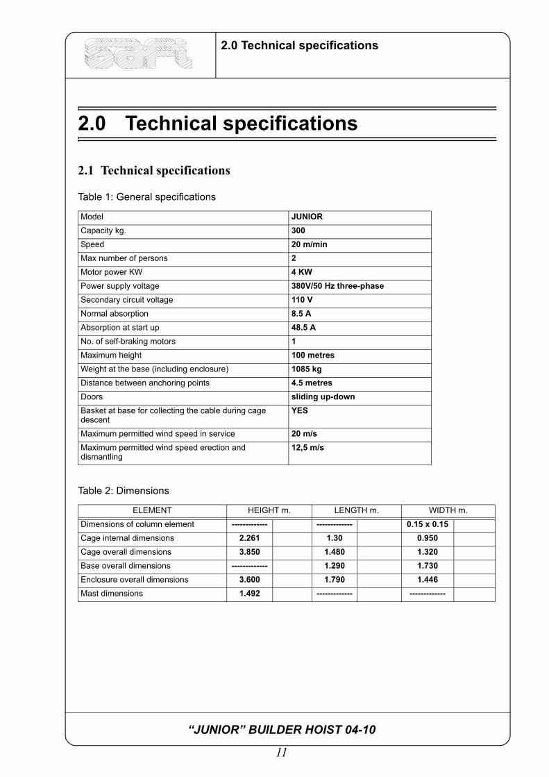
Table 1: General specifications
Model JUNIORCapacity kg. 300Speed 20 m/minMax number of persons 2Motor power KW 4 KW Power supply voltage 380V/50 Hz three-phaseSecondary circuit voltage 110 VNormal absorption 8.5 AAbsorption at start up 48.5 ANo. of self-braking motors 1Maximum height 100 metresWeight at the base (including enclosure) 1085 kgDistance between anchoring points 4.5 metresDoors sliding up-down Basket at base for collecting the cable during cage descent
YES
Maximum permitted wind speed in service 20 m/sMaximum permitted wind speed erection and dismantling
12,5 m/s
Table 2: Dimensions
ELEMENT HEIGHT m. LENGTH m. WIDTH m.
Dimensions of column element ------------- ------------- 0.15 x 0.15Cage internal dimensions 2.261 1.30 0.950Cage overall dimensions 3.850 1.480 1.320Base overall dimensions ------------- 1.290 1.730Enclosure overall dimensions 3.600 1.790 1.446Mast dimensions 1.492 ------------- -------------

“JUNIOR” BUILDER HOIST 04-10
12
2.0 Technical specifications
Tabella 3: WeightsCOMPONENTS kg
Complete base 94
Screw with base 2,4
Vertical element 36,5
End element 31,5
Enclosure frame with door and counterweights 153
Enclosure rear panel 28
Enclosure side panel 33
Complete cage 622
Cage entrance door with frame 62
Cage exit door with frame 70
Electrical panel 22
Gearmotor 55
Centrifugal brake 36
Enclosure door opening slide 1,1
Mobile sliding block for stroke end 1,4
Large guardrail 15,5
Small guardrail 8,5
Cable basket 35
Cable guide 2,8
Anchoring bracket 9
Anchor fixing bracket 6,8
48 mm dia square clamp 1,8
Cable guide arm 4,8
“JUNIOR” BUILDER HOIST 04-10
13
3.0 Description
3.0 Description
3.1 General desriptionThe SAFI builders hoist, model Junior, uses a rack and pinion system driven by a gearmotorto raise the loading cage. The SAFI site hoist permits considerable savings in the running ofmodern building sites. Its special features are:
• Possibility of lifting materials, therefore leaving the site crane free for other uses. • Easy for personnel to reach the various floors for finishing or inspection work.• Safe and time-saving when moving personnel and materials. • Gives the firm greater prestige.• Simple to use and maintain. • Possibility of assembly inside lift shafts (even small ones).
This is possible thanks to its compact structure which exploits all available space.The enclosure and the cage can be dismantled to facilitate transport and loading and unloadingoperations.

“JUNIOR” BUILDER HOIST 04-10
14
3.0 Description
3.2 Overall dimensions
Figura 3.2.1 Overall dimensions

“JUNIOR” BUILDER HOIST 04-10
15
4.0 Machine components
4.0 Machine components
The machine consists of the following components:
Table 4: List of components
Paragraph ref. Assembly
4.0 Assembly
4.1 Base with mast and slide
4.2 Base enclosure
4.3 Vertical and end elements
4.4 Cage with forks and screws for lifting
4.5 Cable collecting basket
4.6 Electric cable
4.7 Cable arm
4.8 Cable guide
4.9 Anchoring
4.10 Standard landing gate
4.11 Optionals for landing gate
4.12 Lifting unit
4.13 Fork
4.14 Guide rollers
4.15 Centrifugal brake
5.0 Safety systems
6.0 Electrical system
12.0 Self-braking motor
“JUNIOR” BUILDER HOIST 04-10
16
4.0 Machine components
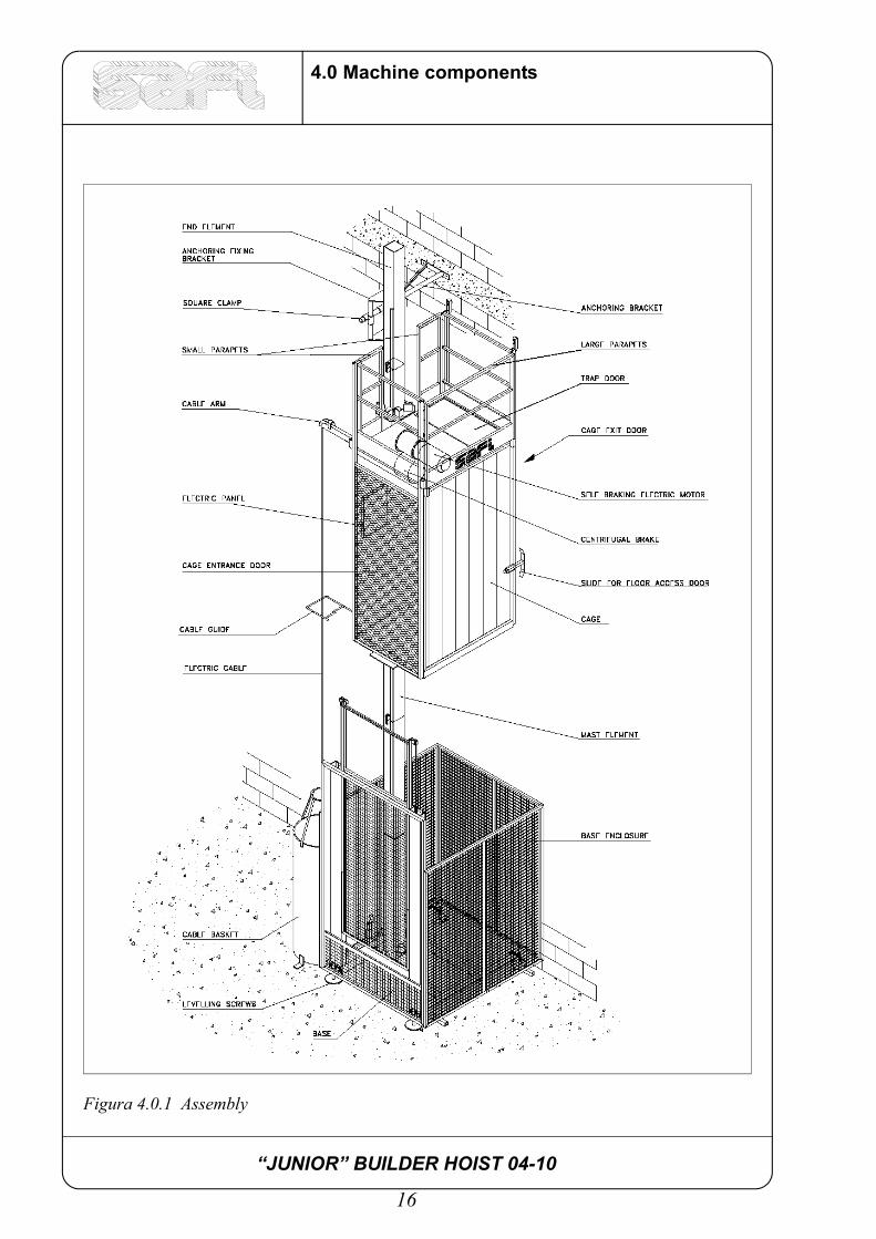
Figura 4.0.1 Assembly

“JUNIOR” BUILDER HOIST 04-10
17
4.0 Machine components
4.1 BaseThe base of the hoist consists of a steel tube base frame which positions and blocks the verticalcolumn and the base enclosure on the ground. The base rests on the ground by means of 5lifting screws. A rubber shock absorber cushions the motor unit if it overshoots the stroke endand comes into contact with the base frame.
Figura 4.1.1 Base

“JUNIOR” BUILDER HOIST 04-10
18
4.0 Machine components
4.2 Base enclosureThe base enclosure is made of tubular panels and steel mesh. The various panels are connectedto one another and to the base frame by means of steel bolts. A safety device prevents the doorfrom opening without the cage. A cable basket is positioned outside the base enclosure. Aspring unwinder can be provided as an optional.
Figura 4.2.1 Base enclosure
“JUNIOR” BUILDER HOIST 04-10
19
4.0 Machine components
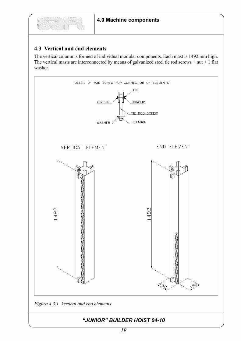
4.3 Vertical and end elementsThe vertical column is formed of individual modular components. Each mast is 1492 mm high.The vertical masts are interconnected by means of galvanized steel tie rod screws + nut + 1 flatwasher.
Figura 4.3.1 Vertical and end elements

“JUNIOR” BUILDER HOIST 04-10
20
4.0 Machine components
4.4 Hoist cage with forks and guardrailsThis is the main component of the machine and consists of a framework in which themechanical and electrical parts for lifting and the safety systems are fitted. The cage frame consists of a tubular steel structure with perimeter panelling made of insulatingpanels and sliding doors provided with electrical and mechanical locking system. Thewalkway and roof are made of non-slip resin-coated multilayer panels. The lifting unit consists of an alternating current 4 KW self-braking gearmotor (it is supplied indirect current version as an optional). The hoist is provided with an emergency brake called parachute which cuts in if the ratedspeed is exceeded during descent.
Figura 4.4.1 Hoist cage with forks and guardrails

“JUNIOR” BUILDER HOIST 04-10
21
4.0 Machine components
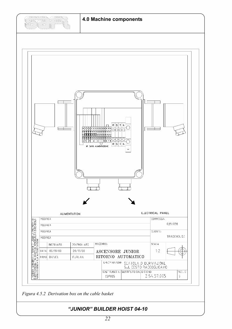
4.5 Cable basketThe cable basket collects the electrical cable hanging from the cable arm. The cable iscollected in tidy coils. The basket is positioned outside the enclosure and is provided with aconnector block to which the cables from the cage and power supply network are connected.
Figura 4.5.1 Cable basket
“JUNIOR” BUILDER HOIST 04-10
22
4.0 Machine components
Figura 4.5.2 Derivation box on the cable basket

“JUNIOR” BUILDER HOIST 04-10
23
4.0 Machine components
4.6 Electrical cableThis is an insulated rubber cable consisting of 3 three-phase leads, an earth lead with adequatesection for the machine installed, a neutral lead, three leads with section of 1.5 mm2 for thelanding gate, control lines and a steel cable coaxial with the cable to prevent the cablestretching during lifting.
4.7 Cable arm Made of tubular profile with section adequate for the weight of the cable. The cable arm isprovided with rounded housing to prevent the cable breaking and coming out. It is fixed to thehoist cage by means of steel bolts.
4.8 Cable guide Designed to contain and vertically guide the electrical cable. The cable guides have the job ofguiding the cable into the Basket. They must be fitted at a height according to requirementsand will therefore be closer near the basket and more spaced out farther up. Fit the cable guidesso that the cable arm provides efficient closure of the cable guides and always check that theyare in good working order.
Figure 4.8.1 - Cable arm Figure 4.8.2 - Cable guide

“JUNIOR” BUILDER HOIST 04-10
24
4.0 Machine components
4.9 Anchoring Wall anchoring must be provided every 4.5 m, normally with anchoring brackets and rawlplugs. The connection between anchoring brackets and mast is by means of vertical mastfixing brackets, square clamps and bolts. The anchoring system is often made to measure inview of the wide range of applications in different building sites.
Figura 4.9.1 Anchoring
“JUNIOR” BUILDER HOIST 04-10
25
4.0 Machine components
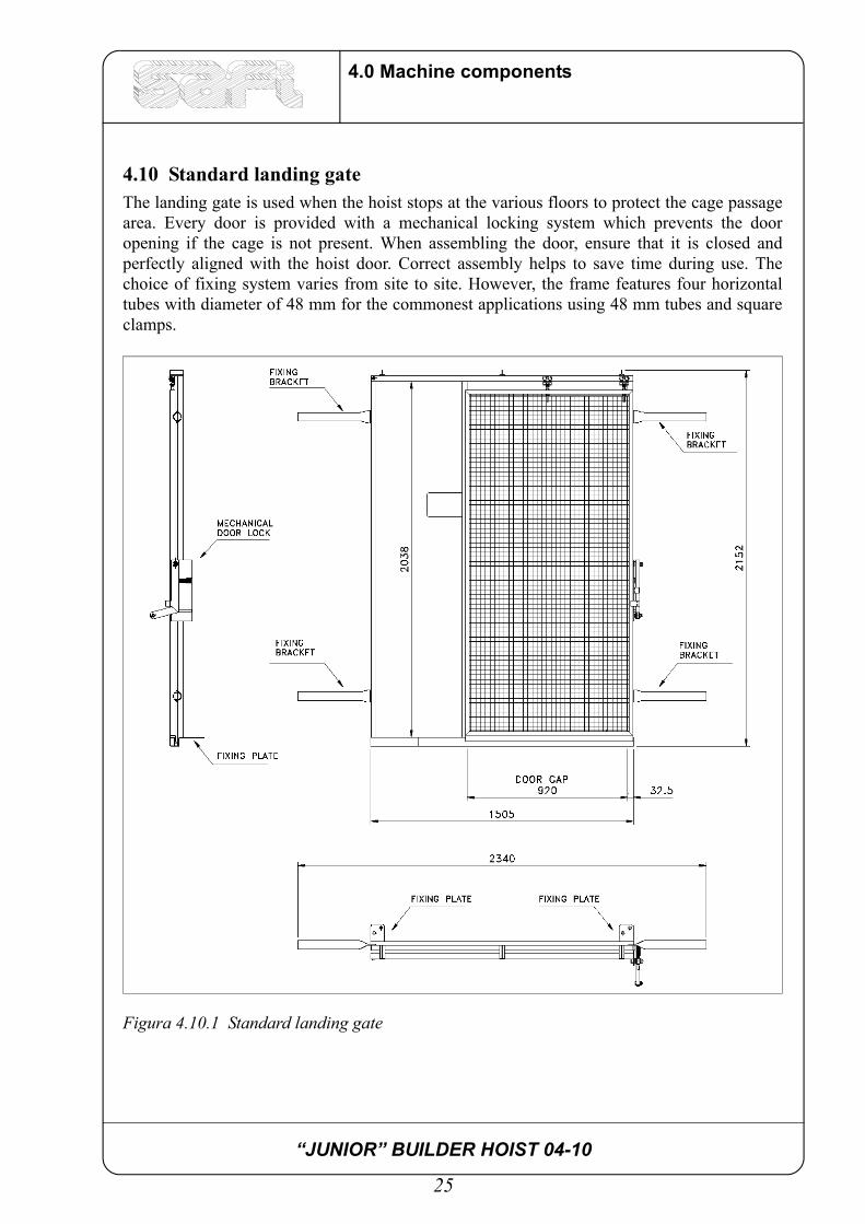
4.10 Standard landing gate The landing gate is used when the hoist stops at the various floors to protect the cage passagearea. Every door is provided with a mechanical locking system which prevents the dooropening if the cage is not present. When assembling the door, ensure that it is closed andperfectly aligned with the hoist door. Correct assembly helps to save time during use. Thechoice of fixing system varies from site to site. However, the frame features four horizontaltubes with diameter of 48 mm for the commonest applications using 48 mm tubes and squareclamps.
Figura 4.10.1 Standard landing gate
“JUNIOR” BUILDER HOIST 04-10
26
4.0 Machine components
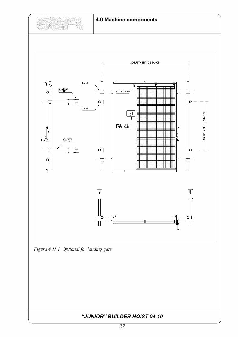
4.11 Optional for landig gateThe landing gate can be provided with the following optionals:
a) - Special fitting for hammerhead craneThis fitting consists of two tubular uprights, fixed to the frame brackets by means ofclamps which act as supports and by the special wall fixing brackets. The position ofthese special brackets can be adjusted and consequently they can adapt to the positionand type of wall fitting.
b) - Landing gate electrical limit switchThe landing gate can be provided with an electrical limit switch which controls whetherthe door is closed or open. If it is open, the limit switch cuts off the power supply, thuspreventing the cage from starting.
c) - Floor call buttonThis is a push-button panel fixed to the door frame and is used to call the cage to therequired floor. The doors are electrically interconnected and connected to the 6-poleplugs of the cable basket.
d) - Semi - automatic stop at floorsThe hoist can be preset for semi-automatic stop at the floors. Normally the cage isstopped at the floor manually when it arrives at the level of the floor. With semi-automatic stop, a light indicates that the cage is arriving at the floor. By releasing theascent or descent button, the cage automatically stops at the floor. If you do not wish tostop at the floor, simply keep the ascent or descent button pressed when the light blinks.The cage will pass the floor and continue its stroke. The light will always blink toindicate that the cage is approaching the floor.
e) - Electronic load limitation systemThis is a system that serves to detect the presence of an overload. It comprises anelectronic panel and a device which is installed on the cage floor. Operation is asfollows:
- If the load inside the cage progressively increases, at a certain point a light will come onto warn that the load is near the maximum permitted limit. If the load continues toincrease, exceeding the limit, an alarm will ring and at the same time a system preventsthe cage from moving until the load is reduced to within the limit.
“JUNIOR” BUILDER HOIST 04-10
27
4.0 Machine components
Figura 4.11.1 Optional for landing gate

“JUNIOR” BUILDER HOIST 04-10
28
4.0 Machine components
4.12 Lifting unit
Figura 4.12.1 Lifting unit
“JUNIOR” BUILDER HOIST 04-10
29
4.0 Machine components
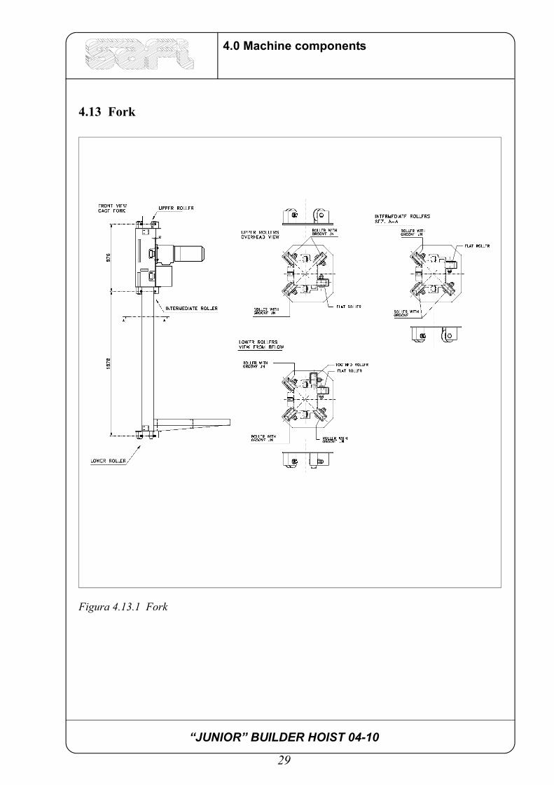
4.13 Fork
Figura 4.13.1 Fork

“JUNIOR” BUILDER HOIST 04-10
30
4.0 Machine components
4.14 Guide rollers
Figura 4.14.1 Toothed guide roller
Figura 4.14.2 Guide roller with groove
“JUNIOR” BUILDER HOIST 04-10
31
4.0 Machine components
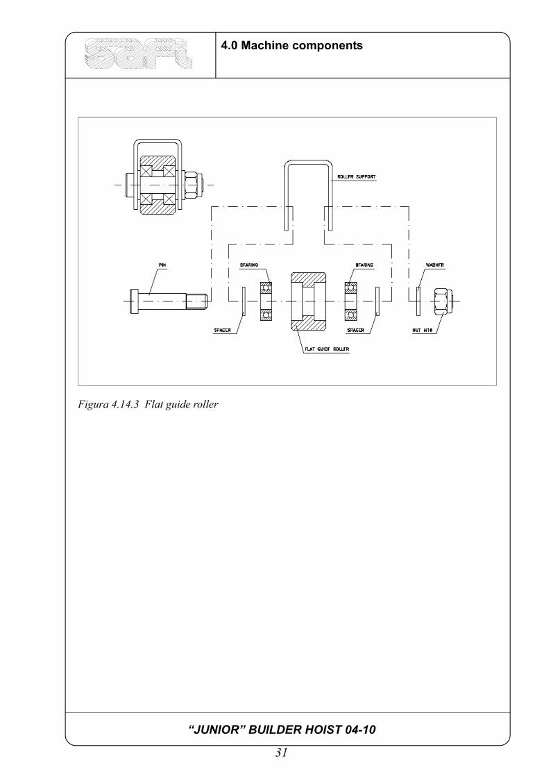
Figura 4.14.3 Flat guide roller

“JUNIOR” BUILDER HOIST 04-10
32
4.0 Machine components
4.15 Centrifugal brakeEvery motor unit is provided with a parachute device which cuts in during descent when themachine exceeds the rated speed (this is exceptional and when it occurs it means that all thekeying and transmission organs of the reducer are broken). If the rated speed is exceeded indescent the centrifugal weight (1) expands, coupling with the fixed weight stop (7) andstopping the weight holder flange(6) and closure flange (4). The shoe (5), connected to theshaft (3) via the gear, continues to rotate until compression between weight holder flange andclosure flange causes the brake shaft, engaged to the rack via pinion (8), to stop. The brakingspace is therefore regulated by compression of the springs (2). The force that counters expansion of the weight at rated speed is caused by a spring. Thisadjustment can be performed by means of a socket wrench via the window located at thebottom of the flange. To do this, the screw of the weight must obviously correspond with the window which isnormally closed by a seal. As a further safety precaution, an electrical limit switch (9) has been fitted near the fixedflange stop so that if the weight couples with the stop, the power to the motor is immediatelycut off.
Figura 4.15.1 Emergency centrifugal brake

“JUNIOR” BUILDER HOIST 04-10
33
4.0 Machine components
4.16 Electrical panelIt is a metal box protected to IP55.It consists of two circuits, one of which is a power circuit for supplying the gearmotor and theother an auxiliary circuit for the panel commands, the limit switches and the indicator lights. The internal part of the panel consists of a transformer for the auxiliary circuit and theprotections for the overloads and for the short circuits.The electrical control panel is built in the electrical panel door and provides the followingfunctions:
• MASTER SWITCH (19):powers the panel.
• KEY SWITCH (4):this is a switch operated by means of a key. If it is not activated, it is not possible to usethe panel.
• START BUTTON (14): sets the motor to start status.
• ASCENT AND DESCENT BUTTON (8) (9): used to control the motor. They must be kept pressed during ascent and descent. Thehoist stops when they are released.
• STOP BUTTON (13):
mushroom button which must be activated in the event of an emergency. To release it,turn 1/4 turn.
• EMERGENCY BRAKE ON LIGHT (16): indicates that the emergency brake thermal switch has cut in, e.g. overload. Wait for it tocool and then switch back on.
• MOTOR THERMAL SWITCH LIGHT (18): Indicates that the motor thermal switch has cut in. Wait for it to cool and then switchback on.
• BRAKE THERMAL SWITCH LIGHT (5): Indicates that the motor thermal switch has cut in. Wait for it to cool and then switchback on.
• EMERGENCY LIGHT (2):
Indicates that the stop button has been activated.• ALARM BUTTON (7):
Serves to activate the alarm on one side of the panel.
In addition there are the sockets and plugs with the following functions:
• FIXED POWER SUPPLY PLUG WITH SOCKET (1):Serves to bring the power supply to the electrical panel via the cable from the cablebasket.
• DOOR PLUG OR ASSEMBLY BUTTON PANEL WITH SOCKETS (17):During assembly the button panel with cable is fitted on this socket, with the ascent -descent controls, and taken to the outside for assembly of the masts.
“JUNIOR” BUILDER HOIST 04-10
34
4.0 Machine components
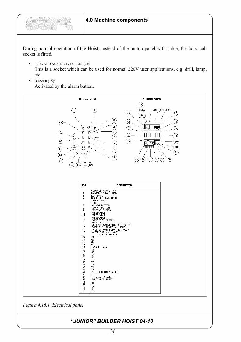
During normal operation of the Hoist, instead of the button panel with cable, the hoist callsocket is fitted.
• PLUG AND AUXILIARY SOCKET (28):
This is a socket which can be used for normal 220V user applications, e.g. drill, lamp,etc.
• BUZZER (15): Activated by the alarm button.
Figura 4.16.1 Electrical panel
“JUNIOR” BUILDER HOIST 04-10
35
5.0 Safety system
5.0 Safety system
1 -Trap door limit switch;
2 -Ascent limit switch;
3 -Descent limit switch;
4 -Emergency limit switch;
5 -Vertical end mast with half rack;
6 -Limit switch on cage entrance and exit doors;
7 -Mechanical lock on cage doors and landing gates;
8 -Automatic cut - in emergency brake;
9 -Motor lock limit switch with emergency brake on;
10 -Flashing light indicating that emergency brake is locked;
11 -Self-braking electronic motor;
12 -Manual brake release device for emergency descent;
13 -Lock out master switch;
14 -Low tension electrical panel with continuos operation type controls and mushroombutton for emergency stop;
15 -Landing gate mechanical lock;
16 -Landing gate limit switch;
17 -Emergency light;
18 -Cage exit door locking system with limit switch;
19 -Alarm;
“JUNIOR” BUILDER HOIST 04-10
36
5.0 Safety system
5.1 Description of safety system1.The trap door limit switch cuts in when the trap door is not closed.
2-3.The ascent and descent limit switches cut in when the hoist cage arrives at thestroke end sliding blocks which are fixed during assembly. With frequent use itmay be necessary to adjust the position of the stroke end sliding blocks, inparticular with a new machine. This is due to bedding in of the braking parts.Cutting in of a limit switch makes it impossible to carry on the same operation andonly allows for a reverse action.
4.The anti slide-out limit switch has a wheel permanently in contact with the verticaltube of the mast and prevents the motor accidentally coming out of the verticalmast. During assembly when the ascent limit switch and the end mast are missing,it prevents ascent once the top has been reached. It must not, however, beconsidered as a working limit switch but as an emergency device and therefore theoperator controlling the cage must operate on the roof in view of the mast
5.The vertical mast is provided with half rack so that if the ascent limit switch slidingblock is exceeded, the lifting unit cannot come out of the vertical column even ifthe ascent limit switch is not working.
6. The cage doors are provided with electrical limit switch preventing movement ofthe cage if the door is not completely closed.
7. The mechanical lock on the enclosure door is a mechanical device designed toprevent opening of the door if the counterdoor is not present.
8.The automatic cut-in emergency brake is an automatically operated braking device,independent of mechanical and electrical lifting devices.
9. The motor lock limit switch prevents the electric motor coming on until the reasonfor cut-in of the emergency brake has been identified and normal operatingconditions have been restored.
10.Cut-in of the limit switch 8 causes the light on the electrical control panel to blink.
11.The lifting unit consists of a worm-screw gearmotor in an oil bath with self-braking electric motor.
12.The manual release device for emergency descent is a simple threaded knob whichmoves the anchor near to the electromagnet and therefore releases the brake.Manual descent must be performed only if the power supply fails, following theprocedure described in paragraph 17.1.
13.The master switch can be locked out so that the machine can be blocked at the endof the work shift. The key must be kept by personnel authorised by the sitemanager.
14.Entrance to the floors is prevented by a door fitted with mechanical lock.
15.This is a device that locks the sliding door when closed. Release is automatic bymeans of a slide on the cage.

“JUNIOR” BUILDER HOIST 04-10
37
5.0 Safety system
16.The landing gate limit switch checks that the door is completely closed. If not, itdoes not give the consent for the cage to start.
17.The emergency light is located inside the cage and comes on when there is a powerfailure. It is controlled by a switch in the electrical panel to prevent it staying onwhen the hoist is not in use.
18.The cage exit door can be provided with a mechanical locking system controlledby an electrical limit switch. This serves to guarantee that the exit door is closedand locked, otherwise the cage is not given the consent to move. The standardlocking system only guarantees that the cage exit door is closed.
19.At the bottom of the cage there is a siren that can be heard at a distance of no lessthan 100 m which signals that the cage is moving.

“JUNIOR” BUILDER HOIST 04-10
38
5.0 Safety system

“JUNIOR” BUILDER HOIST 04-10
39
6.0 Electrical system
6.0 Electrical system
6.1 Wiring diagrams
Figura 6.1.1 Power circuit (with automatic return)
“JUNIOR” BUILDER HOIST 04-10
40
6.0 Electrical system
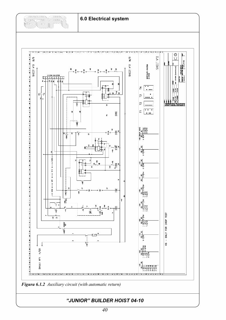
Figura 6.1.2 Auxiliary circuit (with automatic return)
“JUNIOR” BUILDER HOIST 04-10
41
6.0 Electrical system
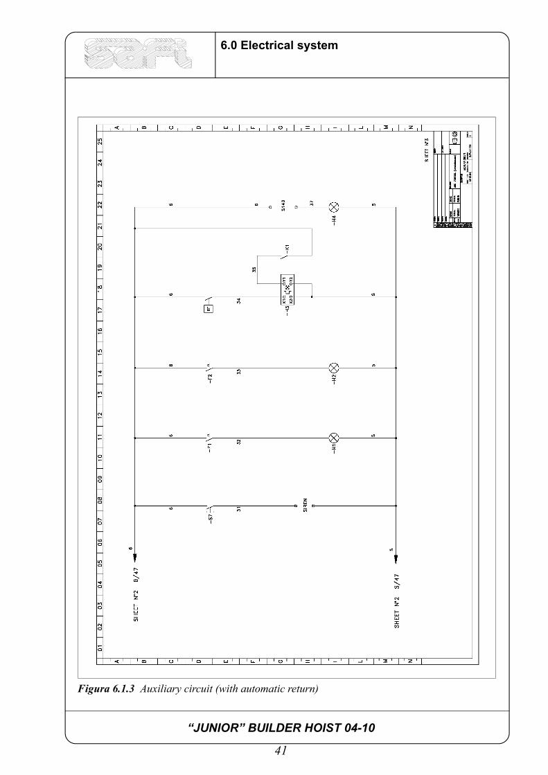
Figura 6.1.3 Auxiliary circuit (with automatic return)

“JUNIOR” BUILDER HOIST 04-10
42
6.0 Electrical system
Figura 6.1.4 Junction terminal board (for circuit with automatic return)
“JUNIOR” BUILDER HOIST 04-10
43
6.0 Electrical system

“JUNIOR” BUILDER HOIST 04-10
44
6.0 Electrical system
“JUNIOR” BUILDER HOIST 04-10
45
7.0 Safety precautions
7.0 Safety precautions
7.1 General precautionsAll the safety precautions for prevention of accidents laid down by the current regulations mustbe observed.
The machine must be installed in its final position by the site manager who must check that all thesafety regulations have been complied with.
Before installation the capacity of the machine supporting surface and the distance from the wall mustbe checked.
All assembly, dismantling, operation and maintenance outside the cage must be performed by trainedauthorised personnel.
The assembly area on the ground must be cordoned off and marked with notices.
Regularly carry out routine and extraordinary maintenance.
During assembly, dismantling and maintenance, disconnect the 6P multiple connector of the powersupply cable to prevent operation of the landing gate buttons.
Ensure that there is nothing protruding from the building which can obstruct the movement of the hoist.
Observe the load limits.
Do not remove the mechanical and electrical safety systems.
Any mechanical or electrical operation must be performed by personnel authorised by the sitemanager who must be informed of the type of operation being performed.
Do not reverse suddenly.
Before pressing a floor call button, ensure that the cage is at a standstill.
Lower the hoist to ground level in bad weather conditions.
Earth the machine and base enclosure and check that the resistance is below 2 Ohms.
In the event of an emergency press the mushroom button and set the master switch to"0".
All the personnel working on the hoist must be familiar with the instructions and precautions containedin this manual. Unauthorised persons are forbidden to operate the machine.
It is forbidden to exceed the hoist loading capacity, as indicated in the technical specifications.
The surface where the base of the hoist rests must be prepared so that it can withstand the load of theentire structure.
Avoid concentrating the loads in one single point of the cage - try to distribute them so that the load isshared over the whole of the available surface.
Lower the hoist to the ground if wind speeds exceed 20 m/s.

“JUNIOR” BUILDER HOIST 04-10
46
7.0 Safety precautions

“JUNIOR” BUILDER HOIST 04-10
47
8.0 Assembly
8.0 Assembly
1 - Prepare the supporting surface for the lift according to the position of the floor exitdoor. The supporting surface sustaining the load should consist, at the supportingpoints, of wooden blocks at least 5 cm thick.
Figura 8.0.1 Preparation of supporting surface
ATTENTION!
INSTALLATION AND ASSEMBLY MUST BE PERFORMED BY QUALIFIED PERSONNEL ONLY WHO MUST SCRUPOLOUSLY FOLLOW THE
INSTRUCTIONS IN THIS MANUAL!

“JUNIOR” BUILDER HOIST 04-10
48
8.0 Assembly
2 - Position the base and level it by means of the screws (using a spirit level resting on thehorizontal parts of the frame). You are advised to tilt the machine slightly towards the wall so that the anchorings arepushing rather than pulling.
3 - Fit the doors with the frames on the cage, the guardrail on the roof and the cable arm.
Figura 8.0.2 Assembly of doors, guardrail, cable arm

“JUNIOR” BUILDER HOIST 04-10
49
8.0 Assembly
4 - Assemble the base enclosure and position the cable basket.
Figura 8.0.3 Assembly of base enclosure

“JUNIOR” BUILDER HOIST 04-10
50
8.0 Assembly
Figura 8.0.4 Base enclosure with cable basket
“JUNIOR” BUILDER HOIST 04-10
51
8.0 Assembly
5 - Check that the cable is neatly coiled in the basket. The first time the lift is operated,check that the cable unwinds correctly and enters the basket. Check that all the thermal switches inside the panel are activated. Check the setting ofthe motor thermal switches according to the specifications on the motor rating plate andcheck the setting of the motor brake thermal switch, approx. 1 A. Press the reset buttonsof the two thermal switches.
6 - Connect the machine to the mains. Leave the multiple socket for the landing gatescontrol circuit free for the moment. In its place insert the assembly push-button panel.When the lift has been assembled at the base, assemble the column for the requiredheight.
7 - Power the cable and then the control panel via the master switch. Check that theemergency button is not pressed. If necessary release it by a quarter of a turn.
8 - Test switch-on of the cage light and siren and operate the push-button panel. Check correct polarity of the motor phases. If they are inverted, the movement of the liftwill also be inverted with respect to the buttons. In this case extreme care must beexercised because if the ascent button is pressed, the lift will move downwards. The descent limit switch located on the mast will also be inverted and will not block thedownward movement of the lift which will be stopped by the rubber shock absorbers.When the push-button panel is operated, a quick descent test must always be performedso that even if the motor phases are correctly connected, the descent limit switch cuts instopping the lift. In this initial assembly phase if there are problems with the motor unit, carry out thefollowing check:Check the setting of the timers inside the panel. One timer must be set by adjusting thetime that elapses from when the descent button is pressed and therefore when the motorbrake comes on, to when you require the electric motor to cut in. This adjustment mustbe performed so that the motor comes on without jerking. Excessively long times mustbe avoided (more than two seconds) as this will cause the emergency brake toautomatically cut in and block the cage.A second timer must be set by adjusting the time between the moment at which themotor stops and the moment at which you wish the brakes to come on. Finally, a thirdtimer must be set by regulating the time during which the external control buttonsremain off from the moment when the lift stops and the personnel can get out
9 - Move the cage so that another mast can be inserted and continue with assembly. Thevertical elements are assembled from the roof. Position an anchoring every 4.5 metres.
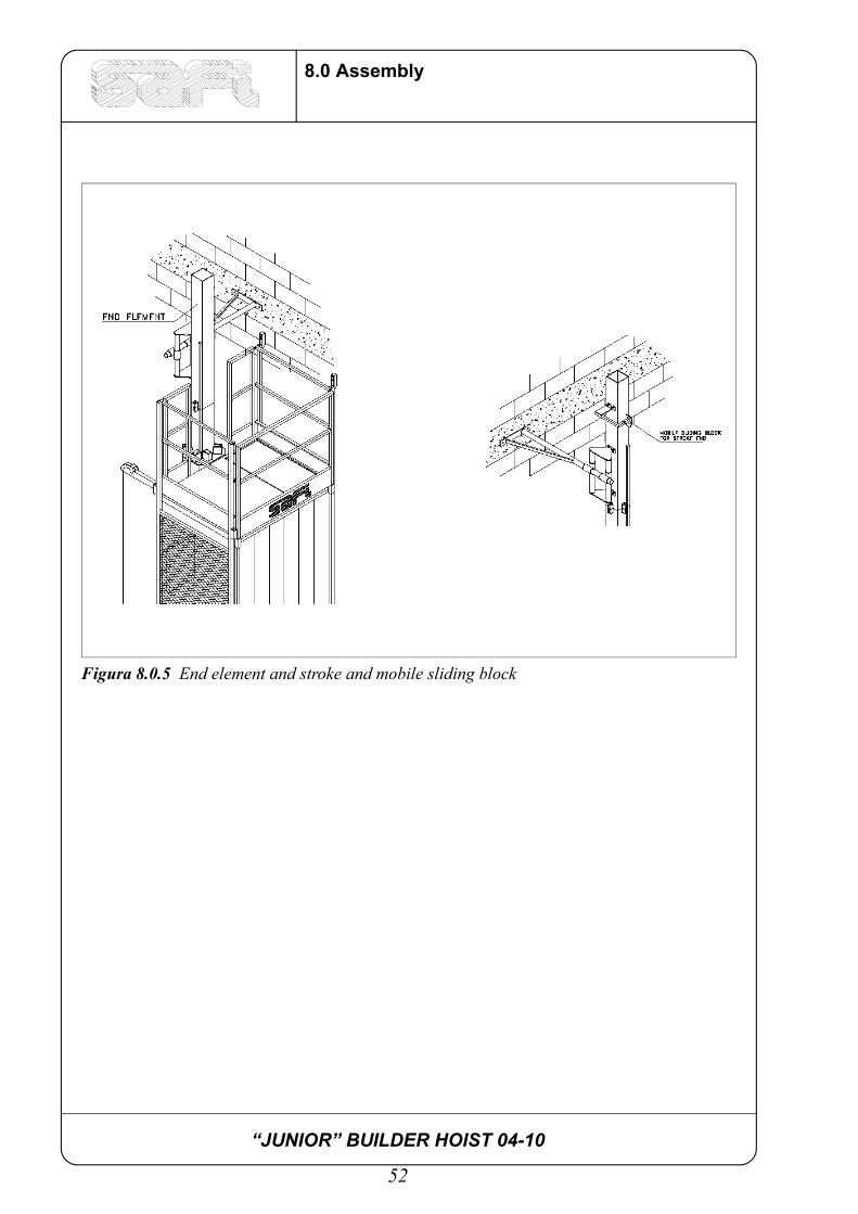
10 - Check that all the protection devices are in perfect working order. 11 - Once you have reached the required height, fix the end element: this can be recognised
by the rack which is half the length of the racks on the other elements. Fix the mobilestroke end slide.
“JUNIOR” BUILDER HOIST 04-10
52
8.0 Assembly
Figura 8.0.5 End element and stroke and mobile sliding block
“JUNIOR” BUILDER HOIST 04-10
53
8.0 Assembly
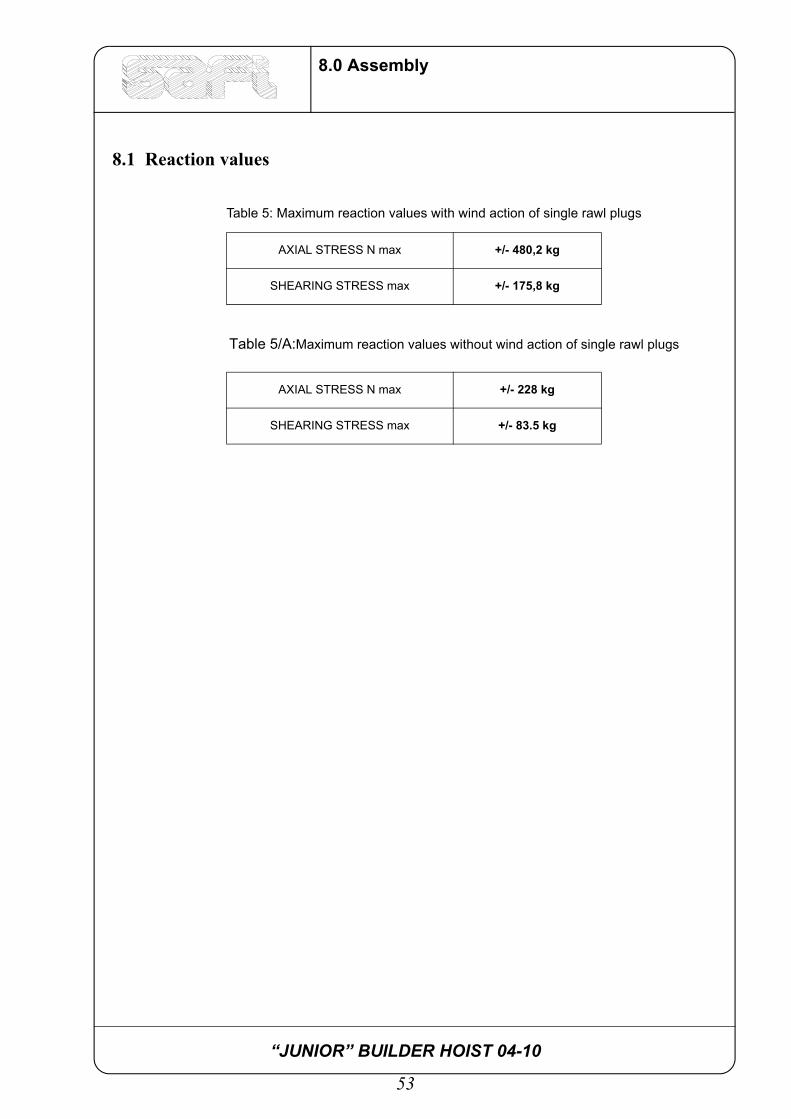
8.1 Reaction values
Table 5/A:Maximum reaction values without wind action of single rawl plugs
Table 5: Maximum reaction values with wind action of single rawl plugs
AXIAL STRESS N max +/- 480,2 kg
SHEARING STRESS max +/- 175,8 kg
AXIAL STRESS N max +/- 228 kg
SHEARING STRESS max +/- 83.5 kg

“JUNIOR” BUILDER HOIST 04-10
54
8.0 Assembly
Figura 8.1.1 Direction of stress

“JUNIOR” BUILDER HOIST 04-10
55
9.0 Use
9.0 Use
At the beginning of the daily work shift, after setting the master switch to “I”, check thefollowing:
- presence of current (test switch-on of cage lights);
- cable neatly coiled in the cable basket;
- perfect condition of safety systems, emergency brake, doors limit switch, ascent/descent limit switch, doors mechanical lock and protective casing;
- perfect condition and efficient working order of the anchorings;
- locking of mast connection bolts;
- check that there is nothing protruding from the building which can interfere with themovement of the cage;
After carrying out these checks, press the ascent button and keep it pressed until the requiredheight is reached. At this point release the button, open the cage sliding door which in its turnwill open the landing gate. With the door open the lift cannot be operated as an electrical limitswitch prevents it from starting. During use the loads must not exceed the maximum valuesgiven in the rating plate and must be evenly distributed. Do not perform sudden operations orreverse manoeuvres as these unnecessarily stress the mechanical parts of the machine.
ATTENTION!
THE MACHINE MUST BE STARTED UP BY QUALIFIELD PERSONNEL ONLY. PERSONNEL MUST TAKE NOTE OF ALL THE
WARNINGS CONTAINED IN THE INSTRUCTION MANUAL. BEFORE STARTING UP, ALL THE DIRECTIONS FOR INSTALLATIONS,
ELECTRICAL CONNECTION AND LUBRICATION MUST BE OBSERVED; ALSO CHECK THAT THE MAINS VOLTAGE
CORRESPONDS TO THE MACHINE VOLTAGE!

“JUNIOR” BUILDER HOIST 04-10
56
9.0 Use
“JUNIOR” BUILDER HOIST 04-10
57
10.0 Dismantling
10.0 Dismantling
To dismantle, perform the assembly operations in reverse order. Remove the 6-pole multiple plug of the landing gates line, fit the plug of the push-button panelfor control from the roof and then position yourself at the highest point of the column to beginthe dismantling phase. Dismantle the masts, landing gates, anchorings and cable guides. Check operation of the ascent overshoot limit switch. Operate the cage, always keeping the central mast in view and ensuring that you do notoverload the cage. Once you reach ground level, disconnect the power supply, dismantle the base enclosurepanelling and dismantle the cage and base using an external crane.

“JUNIOR” BUILDER HOIST 04-10
58
10.0 Dismantling

“JUNIOR” BUILDER HOIST 04-10
59
11.0 Maintenance
11.0 Maintenance
To guarantee perfect operation of the machine, a maintenance programme must be followed incompliance with the general safety precautions; during manual operations the master switchmust therefore be set to "0".
Table 6: Periodical checks
Part to be checked Procedure Frequency
Guide rollers Grease and replace if worn ONCE A WEEK
Lifting pinions Grease and check for wear ONCE A WEEK
Speed reducer Check oil level, eliminate any leaks ONCE A WEEK
Ascent/descent stroke ends Visual control and test to check locking of stroke end sliding blocks
ONCE A WEEK
Cage doors stroke end Efficiency tests ONCE A WEEK
Masts and anchorings connection bolts
Check tightening ONCE A WEEK
Power supply cable Check wear on the external sheath and check that it coils neatly in the cable basket
ONCE A WEEK
Vertical masts Check that the tube and racks are in perfect condition, clean and well-greased. Check tight-ening of the elements
ONCE A WEEK
Cage doors at ground level and at floors
Check that they are in perfect condition and clean and lubricate the carriages and locking devices with grease
ONCE A WEEK
Motor: pinionlifting rollerselectromagnetic brake
Check teethCheck rollers, ball bearings and pinsCheck shoes
EVERY 4-6 MONTHS
Upright: welded partselements
Check weldingsCheck locking screws
EVERY 4-6 MONTHS
Wall anchorings Check rawl plugsCheck clamps
EVERY 4-6 MONTHS
Electrical system General checkCheck power supply cables
EVERY 4-6 MONTHS
ATTENTION!
ENSURE THAT THE TABLE IS DISPLAYED IN A PROMINENT
POSITION!
“JUNIOR” BUILDER HOIST 04-10
60
11.0 Maintenance
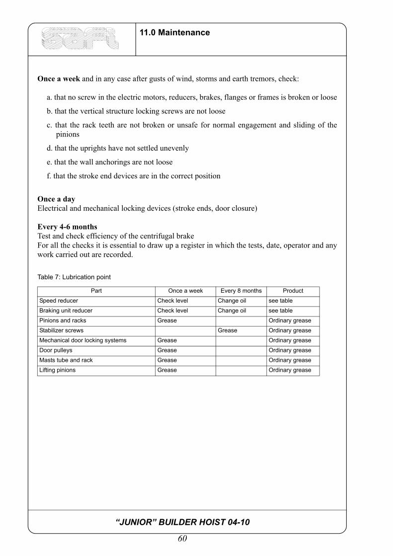
Once a week and in any case after gusts of wind, storms and earth tremors, check:
a. that no screw in the electric motors, reducers, brakes, flanges or frames is broken or loose
b. that the vertical structure locking screws are not loose
c. that the rack teeth are not broken or unsafe for normal engagement and sliding of thepinions
d. that the uprights have not settled unevenly
e. that the wall anchorings are not loose
f. that the stroke end devices are in the correct position
Once a dayElectrical and mechanical locking devices (stroke ends, door closure)
Every 4-6 monthsTest and check efficiency of the centrifugal brakeFor all the checks it is essential to draw up a register in which the tests, date, operator and anywork carried out are recorded.
Table 7: Lubrication point
Part Once a week Every 8 months Product
Speed reducer Check level Change oil see table
Braking unit reducer Check level Change oil see table
Pinions and racks Grease Ordinary grease
Stabilizer screws Grease Ordinary grease
Mechanical door locking systems Grease Ordinary grease
Door pulleys Grease Ordinary grease
Masts tube and rack Grease Ordinary grease
Lifting pinions Grease Ordinary grease
“JUNIOR” BUILDER HOIST 04-10
61
11.0 Maintenance
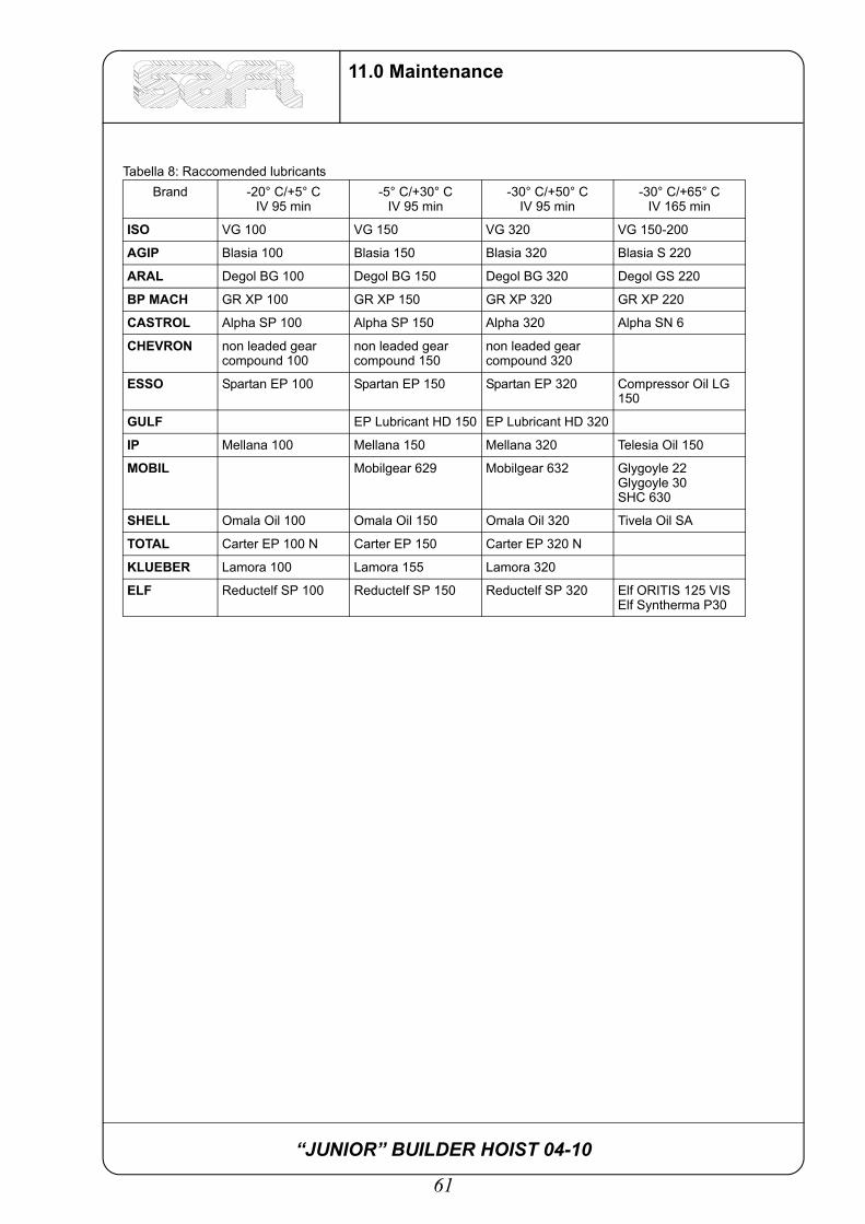
Tabella 8: Raccomended lubricants Brand -20° C/+5° C
IV 95 min-5° C/+30° C
IV 95 min-30° C/+50° C
IV 95 min-30° C/+65° C
IV 165 min
ISO VG 100 VG 150 VG 320 VG 150-200
AGIP Blasia 100 Blasia 150 Blasia 320 Blasia S 220
ARAL Degol BG 100 Degol BG 150 Degol BG 320 Degol GS 220
BP MACH GR XP 100 GR XP 150 GR XP 320 GR XP 220
CASTROL Alpha SP 100 Alpha SP 150 Alpha 320 Alpha SN 6
CHEVRON non leaded gear compound 100
non leaded gearcompound 150
non leaded gearcompound 320
ESSO Spartan EP 100 Spartan EP 150 Spartan EP 320 Compressor Oil LG 150
GULF EP Lubricant HD 150 EP Lubricant HD 320
IP Mellana 100 Mellana 150 Mellana 320 Telesia Oil 150
MOBIL Mobilgear 629 Mobilgear 632 Glygoyle 22Glygoyle 30SHC 630
SHELL Omala Oil 100 Omala Oil 150 Omala Oil 320 Tivela Oil SA
TOTAL Carter EP 100 N Carter EP 150 Carter EP 320 N
KLUEBER Lamora 100 Lamora 155 Lamora 320
ELF Reductelf SP 100 Reductelf SP 150 Reductelf SP 320 Elf ORITIS 125 VISElf Syntherma P30

“JUNIOR” BUILDER HOIST 04-10
62
11.0 Maintenance

“JUNIOR” BUILDER HOIST 04-10
63
12.0 Self-braking unit
12.0 Self-braking unit
Figura 12.0.1 Electric motor self-braking unit
12.1 Components of the self-braking unit
N. DESCRIPTION N. DESCRIPTION412 Snap ring 419 Dust cover ring415 Field magnets 421 Coupling key415.1 Brake coil 422 Snap ring415.2 Brake cap 423 Manual release lever415.5 Brake springs 424 Snap ring415.6 Adjustment ring nut 432 Pad (rotor)415.7 Adjustment ring 433 Clutch sheet-steel417 Fixing screw 601 Fan418 Broached hub 605 Fan cover
“JUNIOR” BUILDER HOIST 04-10
64
12.0 Self-braking unit
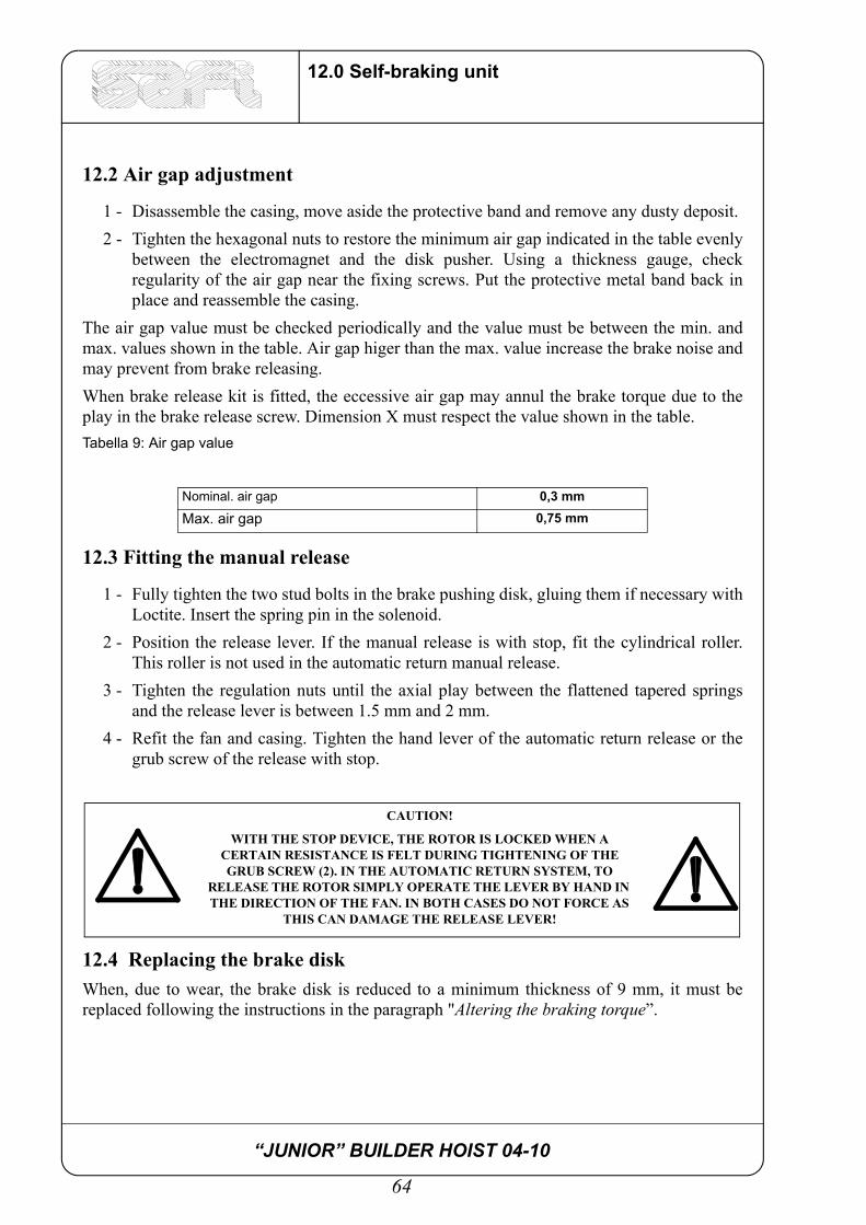
12.2 Air gap adjustment
1 - Disassemble the casing, move aside the protective band and remove any dusty deposit.2 - Tighten the hexagonal nuts to restore the minimum air gap indicated in the table evenly
between the electromagnet and the disk pusher. Using a thickness gauge, checkregularity of the air gap near the fixing screws. Put the protective metal band back inplace and reassemble the casing.
The air gap value must be checked periodically and the value must be between the min. andmax. values shown in the table. Air gap higer than the max. value increase the brake noise andmay prevent from brake releasing.When brake release kit is fitted, the eccessive air gap may annul the brake torque due to theplay in the brake release screw. Dimension X must respect the value shown in the table.Tabella 9: Air gap value
12.3 Fitting the manual release
1 - Fully tighten the two stud bolts in the brake pushing disk, gluing them if necessary withLoctite. Insert the spring pin in the solenoid.
2 - Position the release lever. If the manual release is with stop, fit the cylindrical roller.This roller is not used in the automatic return manual release.
3 - Tighten the regulation nuts until the axial play between the flattened tapered springsand the release lever is between 1.5 mm and 2 mm.
4 - Refit the fan and casing. Tighten the hand lever of the automatic return release or thegrub screw of the release with stop.
12.4 Replacing the brake diskWhen, due to wear, the brake disk is reduced to a minimum thickness of 9 mm, it must bereplaced following the instructions in the paragraph "Altering the braking torque”.
Nominal. air gap 0,3 mm
Max. air gap 0,75 mm
CAUTION!
WITH THE STOP DEVICE, THE ROTOR IS LOCKED WHEN A CERTAIN RESISTANCE IS FELT DURING TIGHTENING OF THE GRUB SCREW (2). IN THE AUTOMATIC RETURN SYSTEM, TO
RELEASE THE ROTOR SIMPLY OPERATE THE LEVER BY HAND IN THE DIRECTION OF THE FAN. IN BOTH CASES DO NOT FORCE AS
THIS CAN DAMAGE THE RELEASE LEVER!

“JUNIOR” BUILDER HOIST 04-10
65
12.0 Self-braking unit
12.5 Maintenance
The only maintenance required is cleaning of the cooling air circulation passages and checkingof the bearings. If the bearings have to be replaced, only use grease resistant to hightemperatures (Esso Unirex N 3).
Figura 12.5.1 Speed reducer
Tabella 10: Speed reducerDESCRIPTION DESCRIPTION
Gearmotor helical in-line Service factor 1,77type ZF68 M112MB4 I L60GH Threephased self-braking motor 4 kW power
Shape B5 Voltate - Frequence 230/400 V 50HzReduction 17,82 Monophase brake supply 190...240
Outside flange diameter 250mm Brake type: L60GHSpeed 81 revs/min Brake with HR manual release and automatic
reversal
ATTENTION!
THE NEW BRAKE DISK MUST NOT UNDER ANY CIRCUMSNTANCES COME INTO CONTACT WITH GREASE OR OIL!

“JUNIOR” BUILDER HOIST 04-10
66
12.0 Self-braking unit
As far as maintenance to the speed reducer are concerned, take into account that:1 - After the first setting at work of the reducer, change the oil every 10,000 hours of
operation, anyway not later than after 2 years.Subsequent oil changes must always be carried out with these same time intervals.Check the oil level inside the reducer at least once a month, verifying this way Do notforget to check the level of oil inside the reducer at least once in a month grantingnormal conditions of working to this component.
2 - Clean the blow-off plug at least once every 3 months to check its perfect working order.
ATTENTION!
FOR THE OIL CHANGE IT IS VERY IMPORTANT TO USE THE SAME TYPE OF OIL USED BEFORE. DIFFERENT KINDS OF OILS MUST
NOT BE MIXED UP. IN PARTICULAR SYNTHETIC OILS CANNOT BE MIXED WITH MINERAL OILS OR WITH OTHER SYNTHETIC OILS. TO CHANGE FROM MINERAL OIL TO SYNTHETIC OIL OR FROM SYNTHETIC OIL OF A CERTAIN TYPE TO ANOTHER, WASH THE
GEAR DRIVE WITH ACCURACY WITH NEW TYPE OF OIL!
“JUNIOR” BUILDER HOIST 04-10
67
13.0 Transport procedures
13.0 Transport procedures
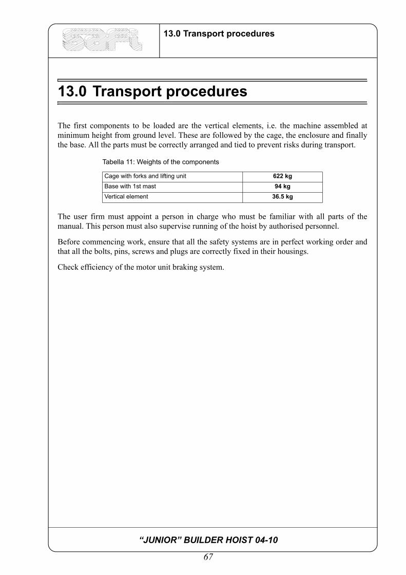
The first components to be loaded are the vertical elements, i.e. the machine assembled atminimum height from ground level. These are followed by the cage, the enclosure and finallythe base. All the parts must be correctly arranged and tied to prevent risks during transport.
The user firm must appoint a person in charge who must be familiar with all parts of themanual. This person must also supervise running of the hoist by authorised personnel.
Before commencing work, ensure that all the safety systems are in perfect working order andthat all the bolts, pins, screws and plugs are correctly fixed in their housings.
Check efficiency of the motor unit braking system.
Tabella 11: Weights of the components
Cage with forks and lifting unit 622 kgBase with 1st mast 94 kgVertical element 36.5 kg

“JUNIOR” BUILDER HOIST 04-10
68
13.0 Transport procedures

“JUNIOR” BUILDER HOIST 04-10
69
14.0 Emergency procedures
14.0 Emergency procedures
If unexpected problems occur during use of the machinery, identify the exact problem and actaccordingly, referring to the relevant chapter in this manual. In particular, the hoist can belowered manually if there is a power failure (see paragraph 16.1) and the mechanicalcentrifugal brake (see paragraph 16.1) reset if the rated descent speed is exceeded.
“JUNIOR” BUILDER HOIST 04-10
70
14.0 Emergency procedures
“JUNIOR” BUILDER HOIST 04-10
71
15.0 Operating hints
15.0 Operating hints
For ascent press the start button and then the ascent button. The hoist automatically locks whenthe ascent button is released. For descent, press the start button and then the descent button.
The stroke end devices automatically stop the hoist when it reaches the upper or lower limit.
The control panel features a red emergency stop button which must be manually activated.
“JUNIOR” BUILDER HOIST 04-10
72
15.0 Operating hints
“JUNIOR” BUILDER HOIST 04-10
73
16.0 Troubleshooting
16.0 Troubleshooting
Before delivery, the hoist is tested together with its electrical control panel to check operationof the control, safety and emergency devices in real operating conditions. The hoist isdelivered ready for many years of trouble-free operation. External factors, for example sudden changes in temperature, vibration and normal wear ofsome components can, however, cause problems. Below is a list of problems which, in our experience, are most likely to occur on site andwhich, although not serious, result in stoppage of the hoist and consequent loss of production.Any work on the electrical system must be carried out by authorised personnel only incompliance with the safety regulations for maintenance of electrical circuits in order to preventaccidents and injuries.
“JUNIOR” BUILDER HOIST 04-10
74
16.0 Troubleshooting
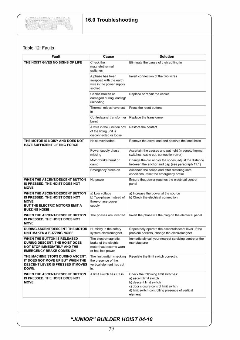
Table 12: Faults
Fault Cause SolutionTHE HOIST GIVES NO SIGNS OF LIFE Check the
magnetothermal switches
Eliminate the cause of their cutting in
A phase has been swapped with the earth wire in the power supply socket
Invert connection of the two wires
Cables broken or damaged during loading/unloading
Replace or repair the cables
Thermal relays have cut in
Press the reset buttons
Control panel transformer burnt
Replace the transformer
A wire in the junction box of the lifting unit is disconnected or loose
Restore the contact
THE MOTOR IS NOISY AND DOES NOT HAVE SUFFICIENT LIFTING FORCE
Hoist overloaded Remove the extra load and observe the load limits
Power supply phase missing
Ascertain the causes and put right (magnetothermal switches, cable cut, connection error)
Motor brake burnt or damp
Change the coil and/or the shoes, adjust the distance between the anchor and gap (see paragraph 11.1)
Emergency brake on Ascertain the cause and after restoring safe conditions, reset the emergency brake
WHEN THE ASCENT/DESCENT BUTTON IS PRESSED, THE HOIST DOES NOT MOVE
No power Ensure that power reaches the electrical control panel
WHEN THE ASCENT/DESCENT BUTTON IS PRESSED, THE HOIST DOES NOT MOVEBUT THE ELECTRIC MOTORS EMIT A BUZZING NOISE
a) Low voltageb) Two-phase instead of three-phase power supply
a) Increase the power at the sourceb) Check the electrical connection
WHEN THE ASCENT/DESCENT BUTTON IS PRESSED, THE HOIST DOES NOT MOVE
The phases are inverted Invert the phase via the plug on the electrical panel
DURING ASCENT/DESCENT, THE MOTOR UNIT MAKES A BUZZING NOISE
Humidity in the safety system electromagnet
Repeatedly operate the ascent/descent lever. If the problem persists, change the electromagnet.
WHEN THE BUTTON IS RELEASED DURING DESCENT, THE HOIST DOES NOT STOP IMMEDIATELY AND THE EMERGENCY BRAKE COMES ON
The electromagnetic brake of the electric motor has become worn or has lost power
Immediately call your nearest servicing centre or the manufacturer
THE MACHINE STOPS DURING ASCENT. IT DOES NOT MOVE UP BUT WHEN THE DESCENT LEVER IS PRESSED IT MOVES DOWN.
The limit switch checking the presence of the vertical element has cut in.
Regulate the limit switch correctly.
WHEN THE ASCENT/DESCENT BUTTON IS PRESSED, THE HOIST DOES NOT MOVE.
A limit switch has cut in. Check the following limit switches:a) ascent limit switchb) descent limit switchc) door closure control limit switch d) limit switch controlling presence of vertical element
“JUNIOR” BUILDER HOIST 04-10
75
17.0 General safety precautions
17.0 General safety precautions
All the operations given below must be performed only by trained and instructed personnel.
The hoist is operated by insertion of the key in the key switch on the front of the electricalpanel.
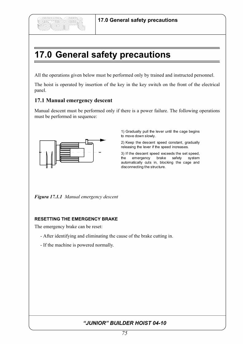
17.1 Manual emergency descent
Manual descent must be performed only if there is a power failure. The following operationsmust be performed in sequence:
Figura 17.1.1 Manual emergency descent
RESETTING THE EMERGENCY BRAKEThe emergency brake can be reset:
- After identifying and eliminating the cause of the brake cutting in.
- If the machine is powered normally.
1) Gradually pull the lever until the cage beginsto move down slowly.
2) Keep the descent speed constant, graduallyreleasing the lever if the speed increases.
3) If the descent speed exceeds the set speed,the emergency brake safety systemautomatically cuts in, blocking the cage anddisconnecting the structure.

“JUNIOR” BUILDER HOIST 04-10
76
17.0 General safety precautions
RESET OPERATION
1) Set the master switch to 0 and open the control panel.
2) Repower with the knob via the master switch inside the panel.
3) Turn the key reset switch and keep it in position for aboutthree seconds. Power will automatically be restored and thehoist will move up, thus resetting the emergency brake.
4) After about three seconds, release the key switch which willautomatically return to position.
5) Reset the master switch to 0 inside the panel.
6) Close the control panel.
7) Use the hoist normally.
“JUNIOR” BUILDER HOIST 04-10
77
18.0 Spare parts list
18.0 Spare parts list
18.1 Mechanical part
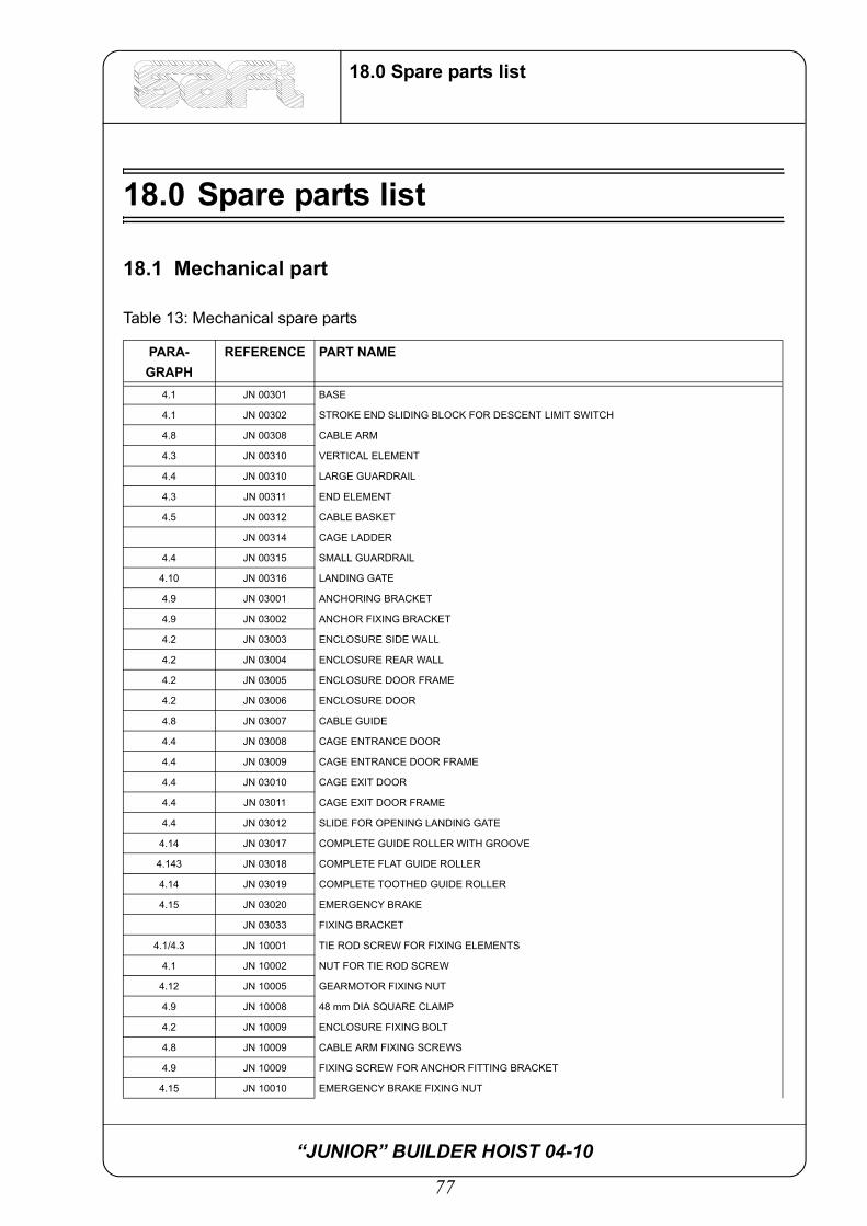
Table 13: Mechanical spare parts
PARA-GRAPH
REFERENCE PART NAME
4.1 JN 00301 BASE
4.1 JN 00302 STROKE END SLIDING BLOCK FOR DESCENT LIMIT SWITCH
4.8 JN 00308 CABLE ARM
4.3 JN 00310 VERTICAL ELEMENT
4.4 JN 00310 LARGE GUARDRAIL
4.3 JN 00311 END ELEMENT
4.5 JN 00312 CABLE BASKET
JN 00314 CAGE LADDER
4.4 JN 00315 SMALL GUARDRAIL
4.10 JN 00316 LANDING GATE
4.9 JN 03001 ANCHORING BRACKET
4.9 JN 03002 ANCHOR FIXING BRACKET
4.2 JN 03003 ENCLOSURE SIDE WALL
4.2 JN 03004 ENCLOSURE REAR WALL
4.2 JN 03005 ENCLOSURE DOOR FRAME
4.2 JN 03006 ENCLOSURE DOOR
4.8 JN 03007 CABLE GUIDE
4.4 JN 03008 CAGE ENTRANCE DOOR
4.4 JN 03009 CAGE ENTRANCE DOOR FRAME
4.4 JN 03010 CAGE EXIT DOOR
4.4 JN 03011 CAGE EXIT DOOR FRAME
4.4 JN 03012 SLIDE FOR OPENING LANDING GATE
4.14 JN 03017 COMPLETE GUIDE ROLLER WITH GROOVE
4.143 JN 03018 COMPLETE FLAT GUIDE ROLLER
4.14 JN 03019 COMPLETE TOOTHED GUIDE ROLLER
4.15 JN 03020 EMERGENCY BRAKE
JN 03033 FIXING BRACKET
4.1/4.3 JN 10001 TIE ROD SCREW FOR FIXING ELEMENTS
4.1 JN 10002 NUT FOR TIE ROD SCREW
4.12 JN 10005 GEARMOTOR FIXING NUT
4.9 JN 10008 48 mm DIA SQUARE CLAMP
4.2 JN 10009 ENCLOSURE FIXING BOLT
4.8 JN 10009 CABLE ARM FIXING SCREWS
4.9 JN 10009 FIXING SCREW FOR ANCHOR FITTING BRACKET
4.15 JN 10010 EMERGENCY BRAKE FIXING NUT
“JUNIOR” BUILDER HOIST 04-10
78
18.0 Spare parts list
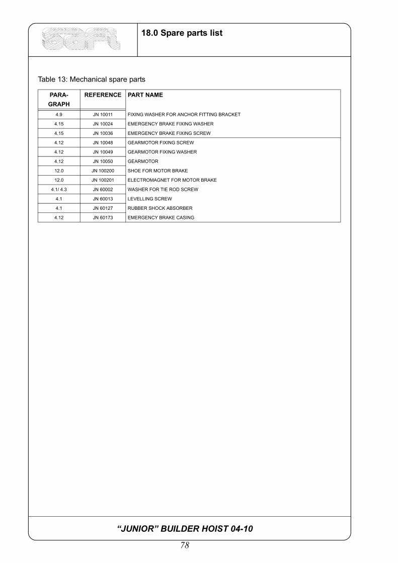
4.9 JN 10011 FIXING WASHER FOR ANCHOR FITTING BRACKET
4.15 JN 10024 EMERGENCY BRAKE FIXING WASHER
4.15 JN 10036 EMERGENCY BRAKE FIXING SCREW
4.12 JN 10048 GEARMOTOR FIXING SCREW
4.12 JN 10049 GEARMOTOR FIXING WASHER
4.12 JN 10050 GEARMOTOR
12.0 JN 100200 SHOE FOR MOTOR BRAKE
12.0 JN 100201 ELECTROMAGNET FOR MOTOR BRAKE
4.1/ 4.3 JN 60002 WASHER FOR TIE ROD SCREW
4.1 JN 60013 LEVELLING SCREW
4.1 JN 60127 RUBBER SHOCK ABSORBER
4.12 JN 60173 EMERGENCY BRAKE CASING
Table 13: Mechanical spare parts
PARA-GRAPH
REFERENCE PART NAME

“JUNIOR” BUILDER HOIST 04-10
79
18.0 Spare parts list
18.2 Electrical part
Table 14: Electrical spare parts
PARAGRAPH REFERENCE PART NAME5.0 JN 10202 COMPLETE LIMIT SWITCH
6.0 JN 10203 FIXED POWER SUPPLY PLUG
6.0 JN 10204 ELECTRICAL PANEL LIGHT
6.0 JN 10205 ELECTRICAL PANEL BUTTON
6.0 JN 10206 COMPLETE MASTER SWITCH
6.0 JN 10207 KEY SWITCH
6.0 JN 10208 ALARM
6.0 JN 10209 6-POLE MULTIPLE CONNECTOR
6.0 JN 10210 SINGLE-PHASE MAGNETOTHERMAL SWITCH
6.0 JN 10211 MAGNETOTHERMAL SWITCH FOR AUXILIARY SOCKET
6.0 JN 10212 REMOTE CONTROL SWITCH
6.0 JN 10213 TIMER
6.0 JN 10214 THERMAL RELAY
6.0 JN 10215 AUXILIARY SOCKET
6.0 JN 10216 TRANSFORMER
6.0 JN 10 217 MAGNETIC SWITCH
4.16 JN 10218 POWER SUPPLY SOCKET
4.6 JN 03029 ELECTRICAL POWER SUPPLY CABLE
4.2 JN 03029 GROUND CALL BUTTON
4.10 JN 03023 FLOOR CALL PUSH-BUTTON PANEL
JN 00319 COMPLETE ASSEMBLY PUSH-BUTTON PANEL WITH CABLE

“JUNIOR” BUILDER HOIST 04-10
80
18.0 Spare parts list
CHECK LIST
INSTALLATION NO. ............................................................... DATE....................................................
SITE ......................................................................................................................................................
SAFETY PROVISIONS: CHECKED BY
................................................................................................ ..................................................
................................................................................................ ..................................................
................................................................................................ ..................................................
................................................................................................ ..................................................
PERSON IN CHARGE: ...........................................................

“JUNIOR” BUILDER HOIST 04-10
81
18.0 Spare parts list
INSTALLATION NO. ............................................................... DATE....................................................
SITE ......................................................................................................................................................
SAFETY PROVISIONS: CHECKED BY
................................................................................................ ..................................................
................................................................................................ ..................................................
................................................................................................ ..................................................
................................................................................................ ..................................................
PERSON IN CHARGE:...........................................................
INSTALLATION NO. ............................................................... DATE....................................................
SITE ......................................................................................................................................................
SAFETY PROVISIONS: CHECKED BY
................................................................................................ ..................................................
................................................................................................ ..................................................
................................................................................................ ..................................................
................................................................................................ ..................................................
PERSON IN CHARGE:

“JUNIOR” BUILDER HOIST 04-10
82
18.0 Spare parts list