asa—cr-194116 nsts-138282 sts-54 · government furnished equipment/flight crew equipment . . . 20...
TRANSCRIPT

"ASA—CR-194116
NSTS-138282
STS-54SPACE SHUTTLEMISSION REPORT
(NASA°CR--194116) STS-54 SPACE N94--13935SHUTTLE MISSION REPORT (LockheedEngineering and Sciences Co.) 34 Q
Unclas
G3/16 0136086
MARCH 1993
LIBRARY COW
MAR 2 5 1993
LANGIE E '-,2Y NASA
HAti^ i}v, VIP.Gt NIA _
IVASANational Aeronautics andSpace Administration
Lyndon S. Johnson Space tenterHouston, Texas
https://ntrs.nasa.gov/search.jsp?R=19940009462 2018-07-09T00:34:01+00:00Z

NSTS-08282
STS-5- 4
SPACE SHUTTLE
MISSION REPORT
P p red by
Robert ricke,LESC/Flight Evaluation •nd
Engineering Office
Approved by
Bobbie 96il SwanSTS-54 Lead Mission Evaluation Room Manager
114zeelp 0000,0David V. Ca
Manager, Flight Engineering Office
Ax,D. M.e m ny
Manager, Orbiter a GFE Projects
jLeonard S. Nicholson
Program Manager, Space Shuttle
Prepared byLockheed Engineering and Sciences Company
forFlight Engineering Office
NATIONAL AERONAUTICS AND SPACE ADMINISTRATIONLYNDON B. JOHNSON SPACE CENTER
HOUSTON, TEXAS 77058
March 1993

STS-54 Table of Contents
Title Page
INTRODUCTION . . . . . . . . . . . . . . . . . . . . . . . 1
MISSIONSUMMARY . . . . . . . . . . . . . . . . . . . . . 1
VEHICLE PERFORMANCE . . . . . . . . . . . . . . . . . . . 4SOLID ROCKET BOOSTER/REDESIGNED SOLID ROCKET MOTORS . . 4EXTERNAL TANK . . . . . . . . . . . . . . . . . . . . . 6SPACE SHUTTLE MAIN ENGINES . . . . . . . . . . . . . . 7SHUTTLE RANGE SAFETY SYSTEM . . . . . . . . . . . . . . 7ORBITrER SUBSYSTEM PERFORMANCE . . . . . . . . . . . . . 8
Main Propulsion System . . . . . . . . . . . . . . . 8Reaction Control Subsystem . . . . . . . . . . . . . 8Orbital Maneuvering Subsystem . . . . . . . 9Power Reactant Storage and Distribution Subsystem . 9Fuel Cell Powerplant Subsystem . . . . . . . . . . . 10Auxiliary Power Unit Subsystem. . . . . . . . . 11Hydraulics/Water Spray Boiler Subsystem . . . 12Electrical Power Distribution and Control Subsystem. 13Environmental Control and Life Support Subsystem . 13Smoke Detection and Fire Suppression . . . . . . . . 15Airlock Support System . . . . . . . . . . . . . . . 15Avionics and Software Subsystems . . . . . . . . . . 15Communications and Tracking Subsystems . . . . . . . 16Structures and Mechanical Subsystems . . . . . . 17Aerodynamics, Heating, and Thermal Interfaces . . . 17Thermal Control Subsystem . . . . . . . . . . . . . 18Aerothermodynamics . . . . . . . . . . . . . . . . . 18Thermal Protection Subsystem . . . . . . . . . . . . 18
EXTRAVEHICULAR ACTIVITY . . . . . . . . . . . . . . . 19GOVERNMENT FURNISHED EQUIPMENT/FLIGHT CREW EQUIPMENT . . . 20PAYLOADS . . . . . . . . . . . . . . . ..
. . . . . 20
TRACKING AND DATA RELAY SATELLITE/INERTIALUPPER STAGE. 20DIFFUSE X-RAY SPECTROMETER . . . . . . . . . . . . 20CHROMOSOME AND PLANT CELL DIVISION IN SPACE . . . . . . 21COMMERCIAL GENERIC BIOPROCESSING APPARATUS . . . . . . 21PHYSIOLOGICAL AND ANATOMICAL RODENT EXPERIMENT . . . . 21SOLID SURFACE COMBUSTION EXPERIMENT . . . . . . . 21
DEVELOPMENT TEST OBJECTIVES/DETAILED SUPPLEMENTARYOBJECTIVES . • . . . . . . . . • • . . • • . 22DEVELOPMENT TEST OBJECTIVES . . . . . . . . . . . . . . 22DETAILED SUPPLEMENTARY OBJECTIVES . . . . . . . . . . . 24
PHOTOGRAPHIC AND TELEVISION ANALYSES . . . . . . . . . 25LAUNCH PHOTOGRAPHIC AND VIDEO DATA ANALYSIS . . . . . . 25ON-ORBIT PHOTOGRAPHIC AND VIDEO DATA ANALYSIS . . . . . 25LANDING PHOTOGRAPHIC AND VIDEO DATA ANALYSIS . . . . . 26
iii
G INTENjIONNik PRECEDING PAGE BLANK NOT FILMED

STS-54 Table of Contents (Concluded)
List of Tables
'FABLE I - STS-54 SEQUENCE OF EVENTS . . . . . . . . . . . 27
TABLE II - STS-54 PROBLEM TRACKING LIST . . . . . . . . . 30
Appendixes
A - DOCUMENT SOURCES . . . . . . . . . . . . . . . . . . . A-1
B - ACRONYMS AND ABBREVIATIONS . . . . . . . . . . . . . . B-1
iv

INTRODUCTION
The STS-54 Space Shuttle Program Mission Report is a summary of the Orbiter,External Tank (ET), Solid Rocket Booster/Redesigned Solid Rocket Motor(SRB/RSRM), and the Space Shuttle main engine (SSME) subsystems performanceduring this fifty-third flight of the Space Shuttle Program, and the thirdflight of the Orbiter vehicle Endeavour (OV-105). In addition to the Orbiter,the flight vehicle consisted of an ET, which was designated ET-51; three SSME's,which were serial numbers 2019, 2033, and 2018 in positions 1, 2, and 3,respectively; and two retrievable and reusable SRB's which were designatedBI-056. The lightweight RSRM r s that were installed in each SRB were designated360L029A for the left SRB, and 360L029B for the right SRB.
The primary objectives of this flight were to perform the operations to deploythe Tracking and Data Relay Satellite-Fllnertial Upper Stage payload and tofulfill the requirements of the Diffuse X-Ray Spectrometer (DXS) payload. Thesecondary objective was to fly the Chromosome and Plant Cell Division in Space(CHROMEX), Commercial Generic Bioprocessing Apparatus (CGBA), Physiological andAnatomical Rodent Experiment (PARE), and the Solid Surface Combustion Experiment(SSCE).
The sequence of events for the six-day STS-54 mission is shown in Table 1 andthe official Orbiter and GFE Projects Problem Tracking List is shown inTable II. Appendix A lists the sources of data, both formal and informal, thatwere provided to prepare this report. Appendix B defines the acronyms andabbreviations used in the document.
` In addition to presenting a summary of subsystem performance, this report alsodiscusses each Orbiter, ET, SSME, SRB, and RSRM in-flight anomaly in theapplicable section of the report. The official tracking number for eachin-flight anomaly, assigned by the cognizant project, is also shown. All timesare given in Greenwich mean time (G.m.t.) and mission elapsed time (MET).
This STS-54 Space Shuttle Program Mission Report fulfills the Space ShuttleProgram requirement, as documented in NSTS 07700, Volume VIII, Appendix E, whichstates that each major organizational element supporting the Program will reportthe results of their hardware evaluation and mission performance plus identifyall related in-flight anomalies.
The crew for this fifty-third Space Shuttle mission was John H. Casper, Col.,USAF, Commander; Donald R. McMonagle, Lt. Col., USAF, Pilot; Mario Runco, Jr.,Lt. Cdr., USN, Mission Specialist 1; Gregory J. Harbaugh, Civilian, MissionSpecialist 2; and Susan J. Helms, Major, USAF, Mission Specialist 3. STS-54 wasthe second space flight for the Commander, Pilot, Mission Specialist 1, andMission Specialist 2, and the first space flight for Mission Specialist 3.
MISSION SUMMARY
The launch of the STS-54 vehicle occurred from KSC launch pad 39B at13:13:59:29.989 G.m.t. (08:59:30 a.m. e.s.t. on January 13, 1993). The launch

was delayed 7 minutes 30 seconds for resolution of a Launch Systems Evaluationand Advisory Team (LSEAT) violation. The vehicle was launched on a directinsertion trajectory with a 28.45-degree inclination. The launch phase wassatisfactory in all respects.
After main engine cutoff (MECO), it was noted that water spray boiler (WSB) 3,while operating on controller A, was no t cooling the lubrication oil ofauxiliary power unit (APU) 3. At a lubrication oil return temperature of 295°F(lubrication oil return temperature is normally controlled to 250 1F), WSB 3 wasswitched to controller B, but again no cooling was evident. As a result, whenAPU 3 bearing temperature 1 reached 335°F, the APU was shut down in accordancewith flight rule 10-5A. Post-ascent data evaluation has shown approximately35 seconds of cooling (water spraying) occurred about 40 seconds after APU 3shutdown while operating on B controller. Analysis indicated that a freeze-upof the VSB occurred. WSB 3/APU 3 cooled normally on both controllers during theflight control system (FCS) checkout and during entry.
Supply pressures in hydraulic system 3 and 1 both showed anomalous pressurerecovery immediately following the post-MECO APU shutdown, and this conditionresulted in the early shutdvw-n of APU 3. The system 3 pressure, following aninitial drop from 3000 psia to 1600 psia over about 6 seconds, increased overthe next 4 seconds to 2400 psia and remained there for more than 40 seconds.During the next 8 seconds, when the thrust vector control (TVC) isolation valveswere closed in a 1, 2, and 3 sequence, system 3 again dropped to the 1600—pciarange, sharply recovered to 2800 psia, and finally dropped to the expectedreservoir pressure. Also, after APU 1 shutdown, hydraulic system 1 showed anunexpected transient pressure recovery. The pressure dropped normally during apostlanding test intended to recreate the problem. Also, the pressure droppednormally during a similar shutdown sequence on a previous flight of OV-105(STS-47). Analysis of the STS-54 data showed that the pressure recovery inhydraulic system 3 was caused by back-driving speedbrake hydraulic motor 3,converting motor into a hydraulic pump which repressurized the shutdown system.Power to operated the back-driving pump was delivered through the differentialgearbox that normally combines the outputs of the three speedbrake motors.
A determination of vehicle performance was made using vehicle acceleration andpreflight propulsion prediction data. From these data, the averageflight-derived engine specific impulse (Isp) determined for the time periodbetween SRB separation and start of 3-g throttling was 452.7 seconds as comparedto an average main propulsion system (MPS) tag value 452.87 seconds.
The 143.8-second orbital maneuvering subsystem (OHS) -2 maneuver was performedas planned with a AV of 222 ft/sec, and the orbiter was placed in a 162 by160 nmi. orbit. The payload bay doors were opened satisfactorily at13:15:41:11 G.m.t. (00:01:41:41 MET).
The Tracking and Data Relay Satellite (TDRS)/Ine •rtial Upper Stage (IUS) payloadwas deployed nominally at 13:20:12:26 G.m.t. (00:06:12:56 MET). The TDRSsatellite is the fifth in a configuration of satellites that form the spacesegment of the Tracking and Data Relay Satellite System (TDRSS). This systemswas developed to provide user services to scientific and applications satellitesin near-Earth orbit and to the Space Shuttle. The TDRS was boosted togeosynchronous orbit by the IUS.
2

At 13:20:27:26.1 G.m.t. (00:06:27:56.1 MET), the OHS 3 separation maneuver fromthe TDRS/IUS was initiated. The firing used the left engine only and was33.7 seconds in duration (AV = 30.4 ft/sec). The firing resulted in a new orbitof 178.9 by 163.0 nmi. System operation during the firing was nominal.
The OMS-4 maneuver was completed nominally at 14:16:08:42.3 G.m.t.(01:02:09:12.3 MET). The OMS-4 maneuver was a right-engine-only firing that was27.3 seconds in duration and provided a 6V of 24.9 ft/sec.
A cabin depressurization to 10.2 psi was completed in preparation for theplanned extravehicular activity (EVA) on flight day 5.
The waste collection system (WCS) commode fault light illuminated at16:14:22:09 G.m.t. (03:00:22:39 MET). A review of data indicates •ghat thecompactor caused the fault light to illuminate during the retraction phase ofthe compaction cycle. A procedure, which was sent via the text and graphicssystem (TAGS), was performed by crewmembers and confirmed the fault, whichdisengages the motor. in-flight, the crew was told to power cycle the commodeprior to use if the light was on, as this re-enables the motor. The WCSoperated satisfactorily for the remainder of the mission. Postflighttroubleshooting confirmed the problem to be the controller logic sensing thecurrent-limit condition too quickly at the end of the cycle and shutting thecompactor down.
The planned EVA was successfully initiated and the EVA crew egressed the Orbiterat 17:10:48 G.m.t. (03:20:49 MET). The EVA was satisfactorily completed and theofficial duration was 4 hours 27 minutes 50 seconds.
Fuel cell 2 was shut down as planned at 18:07:42:25 G.m.t. (04:17:42:55 MET).Fuel cell temperatures decreased as expected. The fuel cell was to remain shutdown for 10 hours to meet the Development Test Objective (DTO). About 9 hoursafter shutdown, the fuel cell stack temperatures had decreased from 185°F to135°F, and the environmental temperature was between 70°F and 80°F, based on thenitrogen system 2 tank 1 temperature. Fuel cell stack 2 temperatures were 130°Fto 135°F at the time of the restart at 18:16:44 G.m.t. (05:02:45 MET). Noanomalies were noted during startup, and the "Ready For Load 11 indication wasreceived 7 minutes after the start command.
The FCS checkout was completed at 18:OB:38:28.6 G.m.t. (04:18:38:58.6 MET).APU 3 and WSB 3 were used with APU 3 running for 14 minutes 47 seconds. All APUparameters were nominal, and the APU was operated until proper cooling wasachieved on both A and B WSB controllers. Two and one-half minutes after sprayinitiation on the B controller, the A controller was selected. About 20 secondslate, a 28-degree over-cool condition was noted during which the lubricationoil return temperature went from 257°F to 227°F before recovering to a nominal255°F where the temperatures stabilized and nominal operation was observed.This overcooling condition did not pose a flight impact.
The rudder speedbrake switching valve failed to switch to the standby positionduring each of the hydraulic system 3 circulation pump activations that occurredduring the mission. During a special run of circulation pump 3, the MPS thrustvector control isolation valve was opened, increasing the differential pressureacross the switching valve. This differential pressure caused the switching
3

valve to move to the standby position. The switching valve performed asexpected during FCS checkout and entry. KSC testing verified that the switchingvalve was operating nominally; however, under certain specific hydraulic balanceconditions, the switching valve may require as long as 30 seconds to changestate.
The reaction control subsystem (RCS) hot-fire was performed at 18:07:57 G.m.t.(04:17:57 MET), and primary thruster R1R failed off due to low chamber pressure(24.7 psia when it should have been 152 psia) on its first firing attempt. Allother thrusters operated nominally. The chamber pressure was at 10 psia for thefirst 280 msec and then jumped to 25 Asia prior to deselection at 320 msec.Injector temperature data indicated that both fuel and oxidizer flow hadoccurred. The most probable failure mode is failure of the oxidizer valve mainstage to open due to nitrate contamination of the pilot stage.
Both payload bay doors were closed nominally by 19:10:04:14 G.m.t.(05:20:04:44 MET). The deorbit maneuver was performed at 19:12:38:10.1 G.m.t.(05:22:38:40.1 MET). The maneuver was approximately 153.4 seconds in durationand the AV was 292.9 ft /sec.
Main landing gear touchdown occurred at Shuttle Landing Facility on concreterunway 33 at 19.13.37:47 G.m.t. (05:23:38:17 MET) on January 19, 1993. Noselanding gear touchdown occurred 15 seconds after main gear touchdown with theOrbiter drag chute being deployed satisfactorily at 19:13:37:59.8 G.m.t. Thedrag chute was jettisoned at 19:13:38:22.6 G.m.t. with wheels stop occurring at19:13:38:36 G.m.t. The rollout was normal in all respects. The flight durationwas 5 days 23 hours 38 minutes 19 seconds. All three APU's were powered down by19:13:56:56.10 G.m.t. The crew completed the required postflightreconfigurations and exited the Orbiter at 19:14:18 G.m.t.
VEHICLE PERFORMANCE
SOLID ROCKET BOOSTER/REDESIGNED SOLID ROCKET MOTOR
All SRB systems performed as expected. The SRB prelaunch countdown was normal.No SRB or RSRM Launch Commit Criteria (LCC) or Operations and MaintenanceRequirements and Specifications Document (OMRSD) violations occurred.
Power-up and operation of all case, igniter, and field joint heaters wasaccomplished routinely. All RSRM temperatures were maintained within acceptablelimits throughout the countdown. For this flight, the heated ground purge inthe SRB aft skirt was used to maintain the case/nozzle joint and flexiblebearing temperatures within the required LCC ranges. The heated ground purgewas also maintained in operation until launch minus 15 minutes to inert the aftskirt area of any accumulation of hydrazine.
Data indicate that the flight performance of both RSRM's was within theallowable performance envelope, and was typical of the performance observed onprevious flights. The RSRM propellant mean bulk temperature (PMBT) was 70°F atlift-off. The RSRM performance is delineated in the table on the followingpage.
4

RSRM PROPULSION PERFORMANCE
Parameter Left motor, 70°F Ri ht motor, 70°FPredicted 1 Actual Predicted Actual
Impulse gagesI-20, 106 lbf-sec 65.84 64.58 65.37 64.821-60, 10 lbf-sec 175.41 172.90 174.37 173.77I-AT, 106 lbf-sec 296.92 296.27 296.75 296.91
Vacuum Isp, lbf-sec/lbm 268.50 267.80 268.50 268.50
Burn rate, in/sec @ 60°F 0.3690 0.3657 0.3676 0.3668at 625 psia
Burn rate, in/sec @ 68°F 0.3716 0.3683 0.3702 0.3694at 625 psia
Event times, secondsIgnition interval 0.232 N/A 0.232 N/AWeb timea 109.50 110.90 110.20 110.80Separation cue, 50 psia 119.50 120.60 120.00 120.00Action time 121.30 122.70 122.00 122.60Separation command, sec 125.44 125.96 125.44 125.96
PMBT, OF 70.00 70.00 70.00 70.00
Maximum ignition rise rate, 90.4 N/A 90.4 N/Apsia/10 ms
Decay time, seconds 2.80 2.70 2.80 3.50(59.4 psia to 85 K)
imbalance Predicted ActualImpulse differential, N/A 707.30b
,Tailoff
klbf-sec
Notes:a All times are referenced to ignition command time except where noted by
the letter a. These items are referenced to lift-off time (Ignitioninterval).
b Tailoff imbalance is equal to left motor minus right motor, and wascalculated by Marshall Space Flight Center.
Postflight evaluation of the RSRM performance data revealed an unexpectedperturbation in the chamber pressure measurements of the right RSRMapproximately 67.5 seconds after lift-off (Flight Problem STS-54-M-1). Theperturbation consisted of a pressure spike of approximately 13-psi maximum withan overall duration of 3 seconds. This pressure increase resulted in a thrustimbalance of 76.5 Klbf. The thrust imbalance approached but did not exceed thespecification thrust imbalance limit of 85 Klbf. Pressure spikes of this naturehave been observed in the past, but this spike is the largest seen during theSpace Shuttle Program. Evaluation of this anomaly was continuing as the time ofreport publication.

RSRM field joint heaters operated for 11 hours and 23 minutes. Power wasapplied to the heating element 22 percent of the time during the prelaunch timeperiod when the LCC was applicable. This amount of heat maintained the fieldjoints in their normal operating temperature range. Igniter joint heatersoperated for 18 hours 17 minutes. Power was applied to the left and rightheating elements 42 and 56 percent of the time, respectively, to keep theigniter joints in their normal operating range.
The flexible bearing temperatures were maintained above 60°F by intermittentactivation of the aft skirt GN2 purge. The purge was operated for a total ofseven hours 15 minutes to keep the nozzle-to-case-joint temperature ar:ve theminimum LCC temperature of 75°F. To ensure all hazardous gases were removedfrom the aft compartment, the purge was operated at high-flow rate fromT-33 minutes to launch. As a result of the purge operation, the flexiblebearing mean bulk temperature was 77°F.
Both SRB's were successfully separated from the ET at T-zero + 125.96 seconds,and reports from the recovery area, based on visual sightings, indicate that thedeceleration subsystem performed as designed. Both SRB's were observed duringdescent, and were retrieved and returned to KSC for disassembly andrefurbishment.
The postflight inspection of the igniter outer joint revealed a hair across theprimary and secondary seal footprints of the aft gasket face on the right RSRM.The cause and corrective action for this condition are being resolved at thiswriting.
EXTERNAL TANK
The ET flight performance was excellent. All objectives and requirementsassociated with the ET propellant loading and flight operations were met. AllET electrical equipment and instrumentation operated satisfactorily. ET purgeand heater operations were monitored and all performed properly. No OMRSDviolations were identified.
Propellant loading was nominal. The ullage pressures in all LO and LH 2 tankswere within acceptable limits throughout loading, pressurization, and flight.The ET pressurization system functioned properly throughout engine start andflight. The minimum liquid oxygen ullage pressure experienced during the periodof ullage pressure slump was a nominal 13.1 psid.
Typical ice/frost formations for the January atmospheric environment wereobserved on the ET during the countdown. Normal quantities of ice or frost werepresent on the liquid oxygen and liquid hydrogen feed lines and on thepressurization line brackets. Also, some frost or ice was present along theliquid hydrogen protruding air load (PAL) ramps. These observations wereacceptable per NSTS 08303. There was no observed ice or frost on the acreage ofthe liquid oxygen or liquid hydrogen tank barrel.
The intertank purge heater and temperature control system operated successfully.There were no LCC, OMRSD, or historical maximum temperature violations. Theobjective of the intertank Purge was met with all temperatures inside theintertank being maintained within acceptable limits. Also, there were nohazardous gas violations in ttnis area.
6

Development Test Objective 312 - ET Thermal Protection System PerformancePhotography - was performed following ET separation. Discussion of the resultsof the photographic evaluation are presented in the Development Test Objectivesection of this re-:;rt.
ET separation was confirmed. Radar data from Bermuda confirmed that the ET(with tumble valve disabled) did not tumble after ET/Orbiter separation. Thepostflight impact point was within the expected footprint and about 37 milesfrom the predicted point.
SPACE SHUTTLE MAIN ENGINE
All SSME parameters appeared normal throughout the prelaunch countdown and weretypical of prelaunch parameters observed on previous flights.
Engine "Ready" was achieved at the planned time, all LCC were met, and enginestart and thrust buildup were normal. All Interface Control Document (ICD)start and shutdown transient requirements were met. Flight data indicate thatSSME performance during start, mainstage, throttling, shutdown and propellantdump operations was as predicted and cutoff times for SSME 1, 2, and 3 were516.29, 516.41, and 516.53 seconds, respectively. The Isp was rated as452.68 seconds based on trajectory data. The high pressure oxidizer turbopump(HPOTP) and high pressure fuel turbopump (HPFTP) temperatures were well withinspecification throughout engine operation. Two anomalies were identified andare discussed in the following paragraphs.
An increase in the SSME 1 HPOTP synchronous vibration amplitude of 1g rms (basedon 11-point sliding average) was noted (Flight Problem STS-54-E-1). Theamplitude increased to a maximum of 3.2g rms at 104 percent on accelerometerlocation 135-1. The average synchronous amplitude of the three HPOTPaccelerometers reached the acceptance test specification of 3g rms. Nobearing-related frequencies were evident at any time during the flight. Thepump was disassembled after flight and no hardware anomalies were found. Thisis consistent with diagnostic disassemblies of ,,amps after ground tests thathave exhibited synchronous vibrations of this magnitude.
A single negative spike of 0.6 psia was noted on the channel A (HPOTP) secondaryseal cavity (SSC) pressure sensor on SSME 3 (Flight Problem STS-54-E-2). Thespike occurred at engine .Mart + 85.6 seconds. No other anomalies occurredduring chill, mainstage, or the post-shutdown phases. The spiking was mostlikely caused by contamination in the pressure transducer. This pressuretransducer had experienced six starts and 1,567 seconds of run time; however,this was the first flight for this sensor. The sensor was replaced. Failureanalysis indicated contamination was present in the sensor; however, a particlecapable of causing the fai lure was not identified.
SPACE SHUTTLE RANGE SAFETY SYSTEM
Shuttle Range Safety System (SRSS) closed-loop testing was completed asscheduled during the launch countdown. All SRSS safe and arm (S&A) devices werearmed and system inhibits turned off at the appropriate times. All SRSSmeasurements indicated that the system operated as expected throughout thecountdown and flight.
7

As planned, the SRB S&A devices were safed, and SRB system power was turned offprior to SRB separation. The ET system remained active until ET separation fromthe Orbiter.
ORBITER SUBSYSTEM
Main Proaulsion Subsystem
The overall performance of the MPS was as expected. Liquid oxygen and liquidhydrogen loading was performed as planned with no stop flows or reverts. NoOMRSD or LCC violations were identified.
Throughout the period of preflight operations, no significant gas concentrationswere detected. The maximum hydrogen concentration level in the Orbiter aftcompartment, which occurred shortly after the start of fast fill, was acorrected value of 135 ppm, and this value compares favorably with previous datafor this vehicle. The oxygen concentration level was 25 ppm, and the heliumconcentration was initially 10,700 ppm, but it fell below the LCC maximum levelof 10,000 ppm before the LCC limits became effective.
A comparison of the calculated propellant loads at the end of replenish, versusthe inventory loads resulted in a loading accuracy of -0.004 percent for liquidhydrogen, and +0.04 percent for liquid oxygen. During loading of the heliumsupply for SSME 2, the helium pressure reached 4500 psis, which is the LCC upperlimit; however, the pressure did not violate the LCC.
Ascent MPS performance appeared to be completely normal. The GO fixed orificepressurization system performed as expected. The GH2 pressurization system alsoperformed nominally. Evaluation of the flow control valve data revealed normaloperations. Preliminary data indicate that the liquid oxygen and liquidhydrogen pressurization systems performed as planned, and that all net positivesuction pressure (NPSP) requirements were met throughout the flight. Thegaseous hydrogen flow control valves for SSME 1 cycled 15 times, 57 times forSSME 2, and 0 tines for SSME 3. Performance analyses of the propulsion systemsduring start, mainstage, and shutdown operations indicated that performance wasnominal and all requirements were met. MECO occurred at lift-off plus509.9 seconds.
The MPS propellant dump operations were nominal, and the MPS operations werenominal during entry and landing, and 55.6 lb of helium were consumed duringentry.
Reaction Control Subsystem
The RCS met all mission requirements in a nominal manner. Propellantconsumption during the six-day mission was 4910.5 lbm, which includes dumpingthe forward RCS to zero percent prior to landing.
The forward RCS thruster FU fuel valve appeared to have a transient leak afterits first firing when the fuel injector temperature dropped to 42°F. Thetemperature began recovering about 30 seconds after the firing. A secondintermittent leak condition was noted about 30 seconds after the seventh firingof thruster F3L. Neither leak was of sufficient magnitude to cause the thruster
8

to be failed by the redundancy management (RM) system. There was no otherforward RCS manifold 3 thruster activity at the time of the leak indications.Data did not snow any repeat of this intermittent leak condition during theremainder of the mission.
Primary thruster R1R failed off due to low chamber pressure (Flight ProblemSTS-54-V-05) on its first firing attempt at 18:07:58:02 G.m.t. (04:17:58:32 MET)during the RCS hot fire. The chamber pressure was 10 Asia for the first280 cosec of the firing, and then jumped to 25 psia just before the thruster wasdeselected at 320 msec. All other thrusters operated nominally. The injectortemperature data indicated that both fuel and oxidizer flow had occurred. Thethruster remained deselected for the remainder of the mission. The mostprobable failure mode is failure of the oxidizer valve main stage to open due tonitrate contamination of the pilot stage.
Orbital Maneuvering Subsystem
The OMS performance was excellent. Four firings of the OMS engines wereperformed of which two were dual-engine firings and the other two weresingle-engine firings. The total firing time was 330.9 seconds for theleft-hand engine and 323.5 seconds for the right-hand engine. Propellantconsumption for the OMS was 12,587 lb with 7885 lb of oxidizer and 4702 lb offuel used.
The gauging system performance was nominal throughout the mission, and allpost-firing quantities were within one percent of calculated values. As aresult, preliminary data indicate that the gauge values should be usable forloading purposes on the next OV-105 flight.
The following table presents the pertinent parameters for each firing.
OMSfiring
Eogineused
Time, G.m.t./MET Firingduration,
sec
AV,ft/sec
2 Both 13:14:38:23.4 G.m.t. 143.8 222.000:00:38:53.4 MET
3 Left-engine 13:20:27:26.1 G.m.t. 33.7 30.400:06:27:56.1 MET
4 Right-engine 14:16:08:42.3 G.m.t. 27.3 24.901:02:09:12.3 MET
Deorbit Both 19:12:38:10.2 G.m.t. 153.4 292.905:22:38:40.2 MET
Power Reactant Storage and Distribution Subsystem
The power reactant storage and distribution (PRSD) subsystem performed nominallythroughout the mission. The vehicle was flown in a four-tank-set configuration,

and a total of 1471.4 lb lb of oxygen and 176.9 lb of hydrogen was consumedduring the mission. Of the oxygen amu,.int used, 66.8 lb of oxygen was used bythe crew for life support. The mission extension capability at an average powerlevel of 14.4 kV was 111.5 hours.
The crew reported during the postflight crew debriefing that an attempt was madeto close the oxygen tank manifold 1 isolation valve prior to the sleep periodfollowing flight day 4 activities. The switch was held on for 2 to 3 seconds,however the valve did not close. A second attempt was made during which theswitch was held in position for 2 seconds, and the valve closed. This is arepeat of the anomaly experienced on this valve during STS-49 (Flight ProblemSTS-49-V-02). Failure analysis was performed on an OV-104 manifold valve whichhas shown similar behavior.
Fuel Cell Powerplant Subsystem
The fuel cells performed nominally in producing 2061.8 kWh of electricity. Inproducing this electricity, the fuel cells also produced 1581.5 lb of water.
The first attempt to wait 72 hours between fuel cell purges was shortened to50 hours when the voltage decay reached the 0.2-volt limit. The voltage decayrate was higher than normal because of slightly higher nitrogen impurity levelsin the oxygen. Reactant purity levels were well within specification, and theobserved voltage decay rate had no mission impact. A total of six purges wereperformed at the following mission elapsed times: 27 hours; 77 hours; 98 hours;111 hours (fuel. cells 1 and 3 only); 123 hours; and 134 hours. The actual fuelcell voltage decay at the end of the mission was 0.1 V above the predicted forfuel cell 1 and 3, and 0.05 V above predicted for fuel cell 2. These decayrates had no effect on the mission.
Fuel cell 2 was shut down as planned at 018:07:42:25 G.m.t. (04:17:42:55 MET).Fuel cell temperatures decreased as expected. The fuel cell was to remain shutdown for 10 hours to meet the DTO. About 9 hours after shutdown, the fuel cellstack temperatures had decreased from 185°F to 135°F, and the environmentaltemperature was between 70°F and 80°F, based on the nitrogen system 2 tank 1temperature. Fuel cell stack 2 temperatures were 130 1F to 135°F at the time ofthe restart at 018:16:44 G.m.t. (05:02:56:30 MET). No anomalies were notedduring startup, and the "Ready For Load" indication was received 7 minutes afterthe start command. The fuel cell operated satisfactorily for the remainder ofthe mission.
During on-orbit operations, the temperature of the fuel cell 2 alternate waterline was higher than normal, indicating water weeping past the fuel cellalternate water line check valve (Flight Problem STS-54-V-07). During entry at19:13:30 G.m.t. (05:23:31 MET), the temperature of the fuel cell 3 alternatewater line began rising and peaked at 127°F 30 minutes after landing (FlightProblem STS-54-V-07). The alternate water line temperature peaking at the sametemperature as the primary water line indicates significant flow past thealternate water line check valve. Modified OMRSD check valve tests will beperformed during turnaround.
10

Auxiliary Power Unit
The APU subsystem performed nominally throughout the mission, but some minorproblems are discussed in the subsequent paragraphs. The following tablepresents the APU run times and fuel consumption by APU serial number andposition.
IAPU 1 (SIN 303) IAPU 2 (SIN 401) IAPU 3 (SIN 207)Flight Phase Time, Fuel Time, Fuel Time, Fuel
min:sec consumption, min:sec consumption, min:sec consumption,lb lb lb
Ascent 20:31 51 20:32 52 19:08 47
FCS checkout 14:47 31
Entrya 62:09 134 83:43 168 61:04 121
Totals 82:0 185 1 104:15 220 94:59 1 199Notes:
a IAPU 1 ran for 18 minutes 28 seconds after landing (touchdown), IAPUran for 19 minutes 09 seconds after landing, and IAPU 3 ran for17 minutes 24 seconds after landing. The lengthened running time wasthe result of special WSB checks that were run after landing.
APU 3 did not receive any hydraulic cooling during ascent (The Hydraulics/daterSpray Boiler Subsystem section of this report contains a detailed discussion ofthe WSB operation during ascent.) As a result of no cooling and prior to theearly shutdown of APU 3, the APU lubrication oil outlet temperature reached317°F (FDA limit = 305°F), lubrication oil return temperature reached 317°F (FDAlimit = 290 0F), gearbox bearing temperature 1 reached 340°F (FDA limit = 335 0F),and gearbox bearing temperature 2 also reached 340°F (No FDA limit). None ofthese temperatures exceeded APU reuse limits. It is suspected that water hadfrozen on the WSB spray bar. APU 3 functioned normally during FCS checkout andduring entry.
The APU 1, 2, and 3 fuel tank/line/water-system B heaters were activated about15 minutes after post-ascent APU shutdown when the test line temperature foreach system approached the lower FDA limit of 48°F. The temperatures returnedto the normal range once heater cycling began. Activation was completed priorto violation of the FDA limit. This same situation occurred the previous twoflights of OV-105 and is normal for the configuration of OV-105. Postflightanalysis is continuing to determine an appropriate solution to this condition.
The APU 1 fuel pump/gas generator valve module (GGVH) heater system A shiftedits on/off cycle points from about a 15° cycle band to a 10°F band about threedays into the mission. The cycling was repeatable and showed no signs ofdegradation.
The APU 2 and 3 seal cavity drain pressure decreased while on orbit. APU 2decreased from 15 psia to 8 psis over 5 1/2 days and APU 3 decreased from18 psia to 3 psia over 2 days. The leakage was most probably from the drain
11

relief valve, which will be tested during turnaround as a part of the normalOMRSD checks. The relief valves are the new design (-003). Leakage from theAPU 2 seal cavity drain was noted on the previous flight of OV-105 (STS-47).This leakage did not impact normal flight operations.
The FCS checkout was completed at 18:08:38:28.6 G.m.t. (04:18:38:58.6 MET).APU 3 and WSB 3 were used with APU 3 running for 14 minutes 47 seconds. All APUparameters were nominal.
F `.ng entry at 19:13:27 G.m.t. (05:23:47 MET), the APU 3 bearing temperaturewas erratic for a period of 17 seconds (Flight Problem STS-54-V-10). The APUhad been operating for about 35 minutes when the condition occurred. The APUrecovered and operated nominally for the remainder of the mission andpostlanding soakback.
Hydraulics/Water Spray Boiler Subsystem
Hydraulics/water spray boiler operation was acceptable during the STS-54mission.
After MECO, it was noted that WSB 3, while operating on controller A, was notcooling the lubrication oil of APU 3 (Flight Problem STS-54- V-01). At alubrication oil return temperature of 295 °F (lubrication oil return temperatureis normally controlled to 250°F), WSB 3 was switched to controller B, but againno cooling was evident. As a result, when the APU 3 bearing temperature 1reached about 335°F, the APU was shut down in accordance with Flight Rule 10-5A.Post-ascent data evaluation has shown that while operating on B controller,approximately 35 seconds of cooling (water spraying) occurred about 40 secondsafter APU 3 shutdown. Preliminary, analysis indicates that a freeze-up of theWSB occurred.
The FCS checkout was completed using WSB 3 with APU 3 running for 14 minutes47 seconds. The APU was operated until proper cooling was achieved on both Aand B WSB controllers. Two and one-half minutes after spray initiation on theB controller, the A controller was selected. About 20 seconds later, a28-degree over-cool condition was noted during which the lubrication oil returntemperature went from 257°F to 227 °F before recovering to a nominal 255°F wherethe temperatures stabilized and nominal operation was observed. Thisovercooling condition did not pose a flight impact.
Supply pressures in hydraulic system 3 and 1 both showed anomalous pressurerecovery immediately following the post-MECO APU shutdown, and this conditionresulted in the early shutdown of APU 3. The system 3 pressure, following aninitial drop from 3000 psia to 1600 psia over about 6 seconds, increased overthe next 4 seconds to 2400 psia and remained there for more than 40 seconds(Flight Problem STS-54-V-08). During the next 8 seconds, when the thrust vectorcontrol (TVC) isolation valves were closed in a 1, 2, and 3 sequence, system 3again dropped to the 1600-psia range, sharply recovered to 2800 psia, andfinally dropped to the expected reservoir pressure. Also, after the normalAPU 1 shutdown, hydraulic system 1 showed an unexpected transient pressurerecovery. The pressure dropped normally during a postlanding test intended torecreate the problem. Also, the pressure dropped normally during a similarshutdown sequence on a previous flight of OV-105 (STS-47).
12

Analysis of the STS-54 data showed that the pressure recovery in hydrauli:system 3 was caused by back-driving speedbrake hydraulic motor 3, converting themotor into a hydraulic pump which repressurized the shutdown system. Power tooperate the back-driving pump was delivered through the differential gearboxthat normally combines the outputs of the three speedbrake motors.Additionally, the APU 2 and 3 data showed an abrupt 8-horsepower increase duringthe 40-second period, and this closely correlated with the 8.4 horsepowerrequired in system 3 to pump the estimated 6 gallons per minute quiescent flowto the observed 2400 psia.
Two concurrent conditions must exist for back-drive to occur; that is thespeedbrake must have the hard-closed command present, and the supply pressure inone of the hydraulic supplies must have declined to a threshold range for anadequate dwell time (> 2 seconds). The conditions leading to the observedpressure recovery are a previously unrecognized characteristic of therudder/speedbrake system, rather than a failure of system components. Adetailed assessment of the effects of this condition on the ascent and entryflight performance indicate that the systems can withstand this condition,although it is undesirable.
Electrical Power Distribution and Control
The electrical power distribution and control (EPDC) subsystem performedsatisfactorily throughout the mission. Performance of the EPDC components ofthe drag chute system performed satisfactorily.
Fuel cell 2 was shut down for 9 hours in support of DTO 0412. The fuel cell wassuccessfully restarted with the ready-to-load indications received seven minutesafter the start command.
During the crew debriefing, the crew reported having difficulty sleeping becauseof the excessive acoustical noise generated by the extravehicular mobility unit(EMU) power supply and battery charger (Flight Problem STS-54-V-11). A requestto obtain acoustical data on STS-57 is being recommended so that the propercorrective action can be taken.
Environmental Control and Life Support Subsystem
The active thermal control system (ATCS) performed nominally throughout themission with the exception of one failure that occurred prior to 'launch. Theflash evaporator system (FES) high-load duct temperature measurement, located onthe outboard zone, did not rise at its normal rate when heater string A wasactivated. Troubleshooting conducted on redundant heater strings B and Cverified that both strings were functioning properly. Heater string B wasselected for launch and operated within its control band for the remainder ofthe mission.
FES temperature oscillations were noted during ascent and , also during thedeorbit preparations. The oscillations were similar to those experienced on thetwo previous flights of this vehicle. This condition did not impact operations.No oscillations were seen with the primary B controller used for entry.
13

The radiator cold soak provided cooling for 4 minutes after landing. Theammonia boiler system (ABS) primary B was operated for 35 minutes, and theprimary A was operated for 20 minutes before ground cooling was connected andoperational.
The atmospheric revitalization system (ARS) performance was nominal throughoutthe mission with no problems identified. The CO 2 partial pressure wasmaintained below a nominal level of 3.50 mm Hg. The cabin air temperature andrelative humidity peaked at 80°F and 56 percent, respectively. The avionicsbays 1, 2, and 3 air outlet temperatures peaked at 104.°F, 105°F, and 87°F,respectively. The avionics bays 1, 2, and 3 water coldplate temperatures peakedat 89°F, 90°F, and 79°F, respectively.
The pressure control system parameters all remained within anticipated rangesthroughout the mission. The pressure control system was used in support of thecabin depressurization to 10.2 psia on flight day 3, the airlock and cabinrepressurizations on flight day 5.
Based on nitrogen consumption (1.8 lbm/day vs. 4.5 lbm/day), an unusually lowcabin pressure leakage was noted throughout the mission. Additionally, odorswere noted by the crew in the area of the volume F. These two factors indicatethat adequate venting was not being provided to the volume F wet trash.Postflight checks by KSC personnel revealed a dynatube adapter plug in theopening of the wet trash to vacuum. (This problem was initially defined asFlight Problem STS-54-V-06; however, a decision was made to delete this item asan anomaly and transfer it to KSC as an action item to be corrected.)
The supply water and waste management system performed normally throughout themission. By the completion of the mission, all of the associated in-flightcheckout requirements were performed and satisfied. The FES operatedsatisfactorily in performing all supply water dumps. The supply water dump linetemperature was maintained between 70°F and 104°F throughout the mission withthe operation of the line heater.
Waste water was gathered at the predicted rate with one waste water dump beingperformed at an average dump rate of 1.81 percent/minute (3.0 lb/min). Thewaste dump line temperature was maintained between 54°F and 78°F while thevacuum vent line temperature was maintained between 57°F and 81°F.
At approximately 14:12:59 G.m.t. (00:23:00 MET), the ac bus 1 currents indicatedthat the commode fan was still on after a commode use three hours earlier.Evaluation showed that the commode lid microswitch had probably not closed andswitched the commode fan off after the last use, and that fully closing andlatching the commode lid would switch the fan off. Instructions were given tothe crew who verified that the commode fan was running. The crew then cycledthe commode lid and the fan switched off. To prevent future occurrences of thiscondition, the crew was ins^ructed to ensure that the lid was fully closed andlatched after each use. This condition is not considered a problem, and it didnot impact the flight.
14

The Extended Duration Orbiter (EDO) waste collection system (VCS) operatedsuccessfully throughout the mission on its first flight. At approximately016:14:22:09 G.m.t. (03:00:22:39 MET), the WCS commode fault light illuminated(Flight Problem STS-54-V-03). A review of data indicated that the compactorcaused the fault light to illuminate during the retraction phase of thecompaction cycle. A procedure was performed and confirmed the fault, whichdisengages the motor. In-flight, the crew was told to power cycle the commodeprior to use if the light was on, as this re-enables the motor. Postflighttroubleshooting confirmed the problem to be the controller logic sensing thecurrent-limit con.dition.too quickly at the end of the cycle and shutting thecompactor down. The commode fault disengages the motor. The WCS operatedsatisfactorily for the remainder of the mission.
Smoke Detection and Fire Suppression
All smoke detection system parameters remained within normal ranges throughoutthe flight. The use of the fire suppression system was not required.
Airlock Support System
The airlock system was used to support the extravehicular activity on flightday 5. All airlock system parameters remained within anticipated ranges.
Avionics and Software Subsystems
The integrated guidance, navigation and control subsystem performance wasnominal throughout the flight. During ascent, elevon load relief occurred atapproximately Mach 0.9. This was nominal but not a predicted condition becausethe phenomenon has been observed only two previous times during the SpaceShuttle Program. These two occurrences were on the last two flights of theOV-105 vehicle (STS-47 and STS-49).
The flight control system performed nominally throughout the flight. The rudderspeedbrake secondary switching valve failed to switch to the standby position atnormal circulation pump pressure (TVC isolation valve closed) and nominal returnpressure (Flight Problem STS-54-V-04). During a special run of circulation pump3, the MPS TVC isolation valve was opened by increasing the differentialpressure across the switching valve to 470 psia. This differential pressurecaused the switching valve to move to the standby position. The switching valveperformed as expected during FCS checkout and entry. The preliminary analysishas indicated a sticky switching valve.
The inertial measurement unit (IMU) and star tracker performed satisfactorilythroughout the mission. The data processing system (DPS) hardware and softwarealso performed very well with no anomalies or problems noted.
The displays and controls subsystem performed nominally; however, an anomaly wasnoted in that three payload bay floodlights did not operate properly (FlightProblem STS-54-V-09). The forward starboard and mid starboard floodlightsfailed to illuminate during the EVA. The mid port floodlight did not illuminatefor about 1 hour after switch activation.
15

The operational instrumentation performed nominally with no anomalies orproblems reported.
Communications and Tracking Subsystem
The performance of the communications and tracking subsystem was nominal. Thetactical air navigation (TACAN) 2 was not able to maintain good bearing lockduring much of the countdown period, but the unit operated satisfactorily duringascent and entry.
Payload Operations reported a total of five occurrences of CommunicationsSecurity (COMSEC) equipment hangup when the uplink commands were notauthenticated due to a known characteristic of the particular COMSEC unit. Eachtime the hangup occurred, uplink modulation was removed and reapplied to recoverthe command capability. There is a potential for the COMSEC to hang up and quitprocessing commands when there is a momentary interruption of data to theCOMSEC. This condition is a known characteristic of the COMSEC equipment.
Closed circuit television (CCTV) camera D did not have a scene image (FlightProblem STS-54-V-02A). The downlink video also did not have any scene image;however, random streaks were noted across the image area. Analysis of theCCTV camera D problem has shown that on flight day 1, CCTV camera D originallyproduced normal, good-quality video of payload bay scenes. Approximately 5hours into the flight, it was discovered that the camera temperature had reached54 °C after the camera had remained in operation for an extended period of time.The 54 °C temperature is 9 degrees above the redline temperature at which thecaution and warning system should sound an alarm. However, the alarm had beendisabled to permit use of the camcorder on the downlink. Although the camerashould not have experienced a failure solely due to reaching 54 °C, the hightemperature most likely contributed to the failure. CCTV camera D was checkedlater 'in the mission and the quality of the video was normal, however the cameracontinued to produce unusable video on an intermittent basis.
During the EVA, CCTV camera B was being used in the split-screen mode and asynchronization problem occurred between camera B and the CCTV system (FlightProblem STS-54-V-02B). After the camera was cycled, split-screen operationswere nominal, and the camera continued to operate nominally. Analysisindicates that the problem was caused by camera B and not the video switchingunit. Camera B video will be examined postflight to determine if furthertesting and repair is requested.
Momentary red and green horizontal lines were noted near the lower quarter ofthe image that was seen from downlinked CCTV camera A video (Flight ProblemSTS-54-V-02C). This condition was noted on several of the separate downlinks ofcamera video. Downlink video will be examined during postflight activities todetermine the need for further testing and repair.
The crew reported that when using CCTV camera C on-orbit, only the brighteststars were visible in a low-light scene (Flight Problem STS-54-V-02D). Thiscondition was indicative of a high-gain circuit problem. The camera was removedand sent to Johnson Space Center (JSC) for evaluation.
16

Structures and Mechanical Subsystems
All mechanically actuated subsystems performed nominally. STS-54 was the sixthflight of the drag chute system. The drag chute was deployed as planned priorto nose landing gear touchdown and all operations were nominal. The drag chutewas jettisoned 22.8 seconds after deployment.
Five pieces of black tile, the largest of which measured 8 inches by 1.25 inchesby 0.75 inch were found in the vicinity of the pilot chute at the 6200-footmarker. These tile fragments originated from the vertical stabilizer "stinger"and were dislodged by contact with the drag chute riser lines during deployment.Aside from this usual damage to the vertical stabilizer "stinger", the dragchute functioned normally. All drag chute hardware was recovered, appeared tobe in good condition, and showed no signs of abnormal operation.
The landing and braking data are presented in the following table.
LANDING AND BRAKING PARAMETERS
FromParameter threshold, Speed, Sink rate, ft/sec Pitch rate,
ft keas de /sec
Main gear touchdown 1536 211.5 -2.0 n/aNose gear touchdown 6247 148.9 n/a 2.68
Braking initiation speed 109.6 knots (keas)Brake-on time 25.0 seconds (not sustained)Rollout distance 8,723 feetRollout time 49.2 secondsRunway 33 (concrete) at KSCOrbiter weight at landing 197,470 lb (landing e.r-zimate)
PeakBrake sensor location pressure, Brake assembly Energy,
psia million ft-lb
Left-hand inboard 1 1248 Left-hand outboard 16.21Left-hand inboard 3 1272 Left-hand inboard 17.90Left-hand outboard 2 1284 Right-hand inboard 12.77Left-hand outboard 4 1092 Right-hand outboard 10.96Right-hand inboard 1 1116Right-hand inboard 3 1044Right-hand outboard 2 948Right-hand outboard 4 936
Aerodynamics, Heating, and Thermal Interfaces
The ascent aerodynamics were nominal with elevon load relief being commanded atapproximately Mach 0.9. This load relief was not predicted; however, it hasbeen seen on the previous two flights of OV-105 (STS-47 and STS-49). Although
17

the cause of the load relief is not fully understood, the relief was transientand the system responded as designed. The STS-47 postflight data evaluation wasunable to identify a cause for the load relief on that flight.
The descent aerodynamics were nominal with the control surfaces respondinggenerally as expected. The angle of attack varied 1 to 2 degrees frompredictions between Mach 9.0 and 4.0, but it did not impact the descent in anymanner.
The integrated heating (aerodynamic and plume) was nominal during ascent andheating to the SSME nozzles was nominal.
Thermal Control Subsystem
The performance of the thermal control subsystem (TCS) was nominal throughoutthe mission with only one heater failure occurring prior to launch. All Orbitersubsystem temperatures were maintained within acceptable limits during allphases of the mission.
The FES high load duct outboard zone heater system A failed off prior to launch.This failure did not impact the mission.
Thermal data were obtained on fuel cell/environment decay rates during theperformance of DTO 312 - Fuel Cell Shutdown and Restart on Orbit. These datawere gathered in support of the long-duration Orbiter requirements.
The starboard main landing gear brake line temperature increased to 244°Ffollowing activation of the heaters during deorbit preparation. This conditionhas been noted on previous flights and is being corrected by the investigationinvolving flight problem STS-52-V-18.
Aerothermodynamics
The acreage heating during entry was nominal with all structural temperaturesremaining within limits, and all structural temperature rise rates remainingwithin the experience base. The local heating was also within normal limits.
Thermal Protection Subsystem
The thermal protection subsystem (TPS) performed satisfactorily throughout themission, based on structural temperature response data. The overall boundarylayer transition from laminar to turbulent flow was symmetric. Transitionoccurred at 1220 seconds after entry interface on the forward side of thevehicle (X/L = 0.3), and at 1215 seconds after entry interface on the aftportion of the vehicle (X/L = 0.6).
The inspection of the Orbiter TPS following landing revealed that the TPS hadsustained a total of 131 hits, of which 14 had a major dimension of one-inch orgreater. Debris impact damage, however, was less than average. A comparison ofthese numbers to statistics from previous missions.of similar configurationindicates that the number of hits larger than one inch is less than average.
18

The Orbiter lower surface sustained 80 hits of which 14 had a major dimension ofone inch or greater. The distribution of hits on the lower surface does notsuggest a single source of ascent debris, but it does indicate a shedding of iceand TPS debris from random sources. The Orbiter upper surface had a total of34 hits and none had dimensions greater than one inch. The right side had fivehits, the left side had none, the right OMS pod had 10, the left OMS pod hadtwo, and none of these hits had a major dimension greater than one inch.
No TPS damage was attributed to material from the wheels, tires, or brakes.Damage to the base heat shield tiles was much less than average. The SSME domemounted heat shield (DMHS) closeout blanket sacrificial panels were partiallydetached and some material was missing from 9:00 to 9:30 o'clock on SSME 3. Theouter edge of the SSME 2 panels from 2:30 to 3:30 o'clock were detached and theunderlying batting was exposed. Some of the sacrificial panel and batting wasmissing. The outer blanket edge from 5:30 to 7:00 o'clock on SSME 1 was frayed.All of the remaining DMHS blankets were in excellent condition.
The Orbiter windows 3 and 4 exhibited moderate hazing with several streaks.Only a very light haze was present on the other forward-facing windows. Surfacewipes were taken from windows 1 through 9 for laboratory analysis.
A sweep of the runway after landing revealed the remains of a bird at the6400-foot marker; however, no evidence of contact or damage to the Orbiter fromstriking the bird was found. Unexpected flight hardware found on the runwayconsisted of three 0-felt plugs that were located 8 feet from the runwaycenterline at the 5800-foot marker.
A portable Shuttle thermal imager (STI) was used to measure the surfacetemperatures of three areas of the Orbiter. Twenty-one minutes after landing,the Orbiter reinforced carbon carbon (RCC) nosecap was 243°F. Twenty-eightminutes after landing, the right-hand wing leading edge RCC panel 9 was 186°F,and panel 17 was 182°F.
EXTRAVEHICULAR ACTIVITY
On flight day 4, the crew performed the extravehicular mobility unit (EMU)checkouts while at a cabin pressure of 10.2 psia. Both units performed asexpected, and no anomalies were noted. Following the EMU checkout, the unitsremained attached to the airlock adapter plates in preparation for the plannedEVA on flight day 5 in support of DTO 1210.
The planned EVA was performed on flight day 5 following nominal EMU donning anda 40-minute prebreathe period. During the EVA, both units performed as expectedand both extravehicular crew members were pleased with the EMU. Real-time datawere received from both units throughout the EVA with the exception of the timewhen the S-band communications link was inoperative. Following the EVA, theunits were recharged with oxygen and the batteries were placed on overnightrecharge.
19

Total EVA time for this flight is officially recorded as 4 hours, 27 minutes,50 seconds. This is the time interval between placing the units on internalbattery power and the beginning of airlock repressurization at the end of theEVA.
GOVERNMENT FURBISHED EQUIPMENT/FLIGHT CREW EQUIPMENT
The Government furnished equipment/flight crew equipment performed as designedthroughout the mission.
PAYLOADS
TRACKING AND DATA RELAY SATELLITE/INERTIAL UPPER STAGE SPACECRAFT
The TDRS satellite is the fifth in a configuration of satellites that form thespace segment of the Tracking and Data Relay Satellite System (TDRSS). Thissystems was developed to provide user services to scientific and applicationssatellites in near-Earth orbit and to the Space Shuttle. The TDRS was boostedto geosynchronous orbit by the IUS.
The TDRS/IUS was successfully deployed from the Orbiter cargo bay at13:19:13 G.m.t. (00:06:13 MET). Prior to the IUS solid rocket motor-2 (SRM-2)burn, the B-side stage 1 battery failed. This removed power from the entireB-side and also failed redundant inertial measurement unit (RIMU) channel 3,causing a memory fault on the A-side. Although the A-side took control, itvoted itself not-okay because of the memory fault. In addition, the spacecraftexperienced attitude perturbations that are believed to have been caused byventing from the failed battery. These perturbations were compensated for bythe IUS and the A-side provided the correct mission sequencing for the SRM-2.The TDRS spacecraft successfully separated from the IUS at 14:02:10 G.m.t.(00:13:10 MET). The TDRS spacecraft remains healthy and was in the initialphase of testing as this report was being written. The TDRS drifted at about3 to 5 degrees per day to its checkout position at 150 degrees West longitude,where 5 to 6 weeks of detailed equipment calibration began.
DIFFUSE X-RAY SPECTROMETER
The DXS payload was sponsored by Goddard Space Flight Center and collected dataon X-ray radiation from diffuse sources in deep space. The DXS vas designed todetermine the wavelength and intensity of the strongest X-ray lines emitted bythe hot stellar gases released by supernovas.
The DXS payload was activated soon after the payload bay doors were opened atabout 13:15:30 G.m.t. (00:01:30 MET). The DXS began scanning operations onrevolution 7. On revolutions 10 and 11, the starboard and port instruments,respectively, experienced problems with high counts causing the high voltage toautomatically shut down. It was theorized that these problems were caused by atime lag (very small) of the internal high voltage turn-off logic during thehigh radiation regions of the South Atlantic Anomaly (SAA), and this time lag
20

allowed formation of hydrocarbon deposits on the high-voltage anode wires in thedetectors. A bakeout procedure in which the internal heaters were commanded toa higher temperature followed by a vigorous P-10 gas purge significantlyimproved the results on the port instrument. The starboard instrument continuedto receive these bakeout procedures throughout the mission, enabling it tocapture some useful data.
Because of these problems, 15 extra orbits of data-taking opportunities wereplanned of which 12 were used for scanning, and three for an additional bakeoutprocedure on both instruments. DXS completed its data takes on revolution 90followed by deactivation and instrument relatch o;: revolution 91.
The port instrument obtained 48,915 seconds of confirmed good data of theplanned 55,220 seconds. The starboard instrument obtained 31,200 seconds ofconfirmed good data of the planned 32,850 seconds.
CHROMOSOME AND PLANT CELL DIVISION IN SPACE
The objective of the Chromosome and Plant Cell Division in Space (CHROMEX) wasto investigate reproductive abnormalities which apparently occur in plantsexposed to microgravity.
The CHROMEX activity was monitored by the crew on a daily basis and no anomalieswere noted.
COMMERCIAL GENERIC BIOPROCESSING APPARATUS
The objective of the Commercial Generic Bioprocessing Apparatus (CGBA)experiment was to perform biological sample processing and stow it for return toEarth for evaluation.
All 24 fluid processing apparatus (FPA) sets, containing a total of 192individual FPA's were successfully processed. One set was inadvertentlydeactivated early, but the science was recovered with a workaround procedure.Another FPA set was terminated late with no significant loss of scientific data.
PHYSIOLOGICAL AND ANATOMICAL RODENT rXPERIHENT
The objective of the Physiological and Anatomical Rodent Experiment (PARE) wasto investigate physiological and anatomical changes in rodents exposed tomicrogravity.
The crew observed the animals and the animal enclosure module as plannedthroughout the mission. Temperatures were much as expected and the groundcontrols also functioned as expected.
SOLID SURFACE COMBUSTION EXPERIMENT
The objective of the Solid Surface Combustion Experiment (SSCE) was to measureflame-spread rate, solid--phase temperature, and gas-phase temperature forflames. Data will be used to validate flame-spread models to improve the safetyof spEze travel. The two SSCE burn operations planned for the mission werecompleted satisfactorily, and no problems were encountered.
21

DEVELOPMENT TEST OBJECTIVES/DETAILED SUPPLEMENTARY OBJECTIVES
DEVELOPMENT TEST OBJECTIVES
Fourteen development test objectives were assigned to the STS-54 mission. Ofthese, 12 were accomplished and are discussed in the following paragraphs.
DTO 301D - Ascent Structural Capability Evaluation - Data were collected andrecorded on the modular auxiliary data system (MADS) recorder for this data-onlyDTO. The data have been processed and given to the sponsor for evaluation, andthe results will be presented in separate documentation.
DTO 305D - Ascent Compartment Venting Evaluation - Data were collected andrecorded on the MADS recorder for this data-only DTO. The data have beenprocessed and given to the sponsor for evaluation, and the results will bepresented in separate documentation.
DTO 306D - Descent Compartment Venting Evaluation - Data were collected andrecorded on the MADS recorder for this data-only DTO. The data have beenforwarded to the sponsor for evaluation and reporting.
DTO 307D - Entry Structural Capability - Data were collected and recorded on theMADS recorder for this data-only DTO. The data have been forwarded to thesponsor for evaluation and reporting.
DTO 312 - ET Thermal Protection Subsystem Performance - Two full rolls and onepartial roll of 35-mm film were taken with a Nikon F4 camera equipped with a300-mm lens and a 2x extender which together provide an effective 600-mm focallength lens. Magazines 27 and 28 each contained 37 photographs with excellentexposure. T±e first frame was taken on magazine 27 at 13:14:13:45 G.m.t.(00:00:14:15 MET) and the last frame was taken at 13:14:15:33 G.m.t.(00:00:16:03 MET). The first frame taken from magazine 28 at 13:14:16:37 G.m.t.(00:00:17:07 MET), and the last frame was taken 4 minutes 12 seconds later.The seven additional frames that were obtained on magazine 36 were exposedbetween 3 minutes and 5 minutes after magazine 28. The duration of ETacquisition was 12 minutes 9 seconds.
Magazine 27 viewed the nose cone/ogive and the right side (+Y axis) of the ET.Magazine 28 showed the aft dome and the left side (-Y/+Z axis).
In addition to the photography taken from the flight deck, 60 good qualityframes of the ET were taken on magazine 51 with the 35-mm umbilical well camera.These frames provided views of the LH 2 tank TPS acreage (+Z side), the aft dome,and the ET nose. Data were also obtained on magazine 52 from the 16-mm camerawith a 5-mm lens that was also located in the umbilical well. These data wereused to perform the analysis presented in the following paragraphs.
Magazine 57 of the 16-mm film taken from the umbilical well during SRB and ETseparation and the early portion of the on-orbit phase showed a smallmetallic-appearing disk-shaped object with a probable hollow center shortlyafter ET separation (Flight Problem STS-54-I-01). This object was visible foralmost 200 frames of the 16-mm film. At about the same time, a small
22

metallic-appearing rod-shaped object with possibly a hollow end was noted, andit was shown in almost 400 frames of the film (Flight Problem STS-54-I-01). Thethird item noted was a flexible tape-like object, and it was noted in 187frames (Flight Problem STS-54-I-01).
Relative measurements of the three metallic appearing objects were also made.The actual size of these objects could not be determined because no adequatereference was available in the field of view for comparative scaling. The scaleis not linear with trajectory because the 5 mm camera lens does not have flatoptics and the objects are not near the center of the field of view.
The disk-shaped object was seen between 8 minutes 59 seconds and 9 minutes 0seconds MET (first observed 11.335 seconds after ET separation). The ratio ofthe outside diameter to the height of the disk-shaped object was determined tobe 4.2 to 1 (frame 7511). The ratio of the outside diameter to the innerdiameter of this object was 3.2 to 1 (frame 7461).
The rod-shaped debris was seen between 8 minutes 59.5 seconds and 9 minutes5.7 seconds MET (first observed at 11.65 seconds after ET separation). Theratio of the major axis to the diameter was determined to be 16.2 to 1. Themeasurements of the rod-shaped object was made on frame 7448.
The tape-like debris was seen between 9 minutes 1.6 seconds and 9 minutes02.4 seconds (first seen 13.63 seconds after ET separation). The longestdimension of the tape-like object was 13.6 analyzer units (frame 7935) and thewidth of the object is 2.5 analyzer units (frame 7913). The thickness of thethin dimension was 1.2 analyzer units (frame 7936).
DTO 412 - Fuel Cell On-Orbit Shutdown/Restart - Fuel cell 2 was successfullyshut down and restarted. Temperature data were collected and have been given tothe sponsor for evaluation. The Fuel Cell Powerplant Subsystem section of thisreport contains a detailed discussion of this activity.
DTO 520 - Edwards Lakebed Runway Bearing Strength and Rolling FrictionAssessment for Orbiter Landings - This DTO was not accomplished as the landingoccurred at KSC.
DTO 521 - Orbiter Drag Chute System - The Orbiter drag chute was de ployed duringthe derotation and the drag chute operated satisfactorily. Details arecontained in the Structures and Mechanical subsystem section of this report.
DTO 648 - Electronic Still Photography Test - The electronic still camera wasoperated and no problems were reported. The photography has been given to thesponsor for evaluation.
DTO 656 - PGSC Single Event Upset Monitor - This DTO was accomplished and thedata have been given to the sponsor for evaluation.
DTO 662 - Extended Duration Orbiter WCS Evaluation - The evaluation of theExtended Duration Orbiter (EDO) WCS was completed very satisfactorily with onlyone minor problem. The data have been given to the sponsor for evaluation. TheEnvironmental Control and Life Support Subsystem section of this report containsa detailed discussion of EDO WCS operations and problems.
23

DTO 700-3 - Atmospheric Effects on Star Tracker Performance - Data were taken onthree orbits and have been given to the sponsor for evaluation and reporting inseparate documentation.
DTO 805 - Crosswind Landing Performance - This DTO was not accomplished ascrosswinds did not meet the minimum requirements for this DTO.
DTO 1210 - EVA Operation Procedures/Training - This DTO was accomplished with a4 hour 27 minute 50 second EVA. A discussion of the EVA is contained in theExtravehicular Activity section of this report.
DETAILED SUPPLEMENTARY OBJECTIVES
Twelve Detailed Supplementary Objectives (DSO's) were assigned to the STS-54mission and all 12 were accomplished. Each one is discussed in the followingparagraphs.
DSO 316 - Bioreactor/Flow and Particle Trajectory in Microgravity - The twoplanned tests were completed and the data have been given to the sponsor forevaluation and documenting in separate publications.
DSO 321 - Frequency Interference Measurement - This DSO was completed and thedata have been given to the sponsor for evaluation and reporting. The resultswill be presented in separate documentation.
DSO 322 - Human Lymphocyte Locomotion in Microgravity - This DSO operated asplanned and the data and hardware have been given to the sponsor for evaluation.The sponsor will provide the results in separate documentation.
DSO 476 - In-Flight Aerobic Exercise (Rower) - This was an EDO buildup medicalevaluation DSO. All exercise sessions were completed, and the data have beengiven to the sponsor for evaluation and reporting.
DSO 487 - Immunological Assessment of Crew Members - Data for this DSO weregathered during preflight and postflight operations only. The sponsor has thedata and will report in separate documentation after data evaluation.
DSO 603 - Orthostatic Function During Entry, Landing, and Egress - This was anEDO buildup medical evaluation DSO. Data were collected for this DSO and havebeen given to the sponsor for evaluation and reporting in separatedocumentation.
DSO 604 - Visual-Vestibular Integration - Both 0I-1 and 0I-3 - This was an EDObuildup medical evaluation DSO. These investigations were completed and thedata were given to the sponsor for evaluation and reporting.
DSO 605 - Postflight Recovery of Postural Equilibrium Control - This was an EDObuildup medical evaluation DSO, and data were collected during the preflight andpostflight periods only. The sponsor is in possession of the data and willreport the results in separate documentation after completion of the evaluation.
DSO 802 - Educational Activities - The crew performed the live downlink withfour schools that were planned. In addition, several other sessions were tapedfor use after completion of the flight.
24

DSO 901 - Documentary Television - Data were collected for this DSO and havebeen given to the sponsor for evaluation and reporting in separatedocumentation.
DSO 902 - Documentary Motion Picture Photography - Data were collected for thisDSO and have been given to the sponsor for evaluation and reporting.
DSO 903 - Documentary Still Photography - Data were collected for this DSO andhave been given to the sponsor for evaluation and reporting.
PHOTOGRAPHY AND TELEVISION ANALYSIS
LAUNCH PHOTOGRAPHIC AND VIDEO DATA ANALYSIS
On launch day, 24 of the 24 expected videos were received and reviewed.Following launch day, but during the mission, 54 of 55 expected launch filmswere also reviewed. The review produced no evidence of in-flight anomalies.
ON-ORBIT PHOTOGRAPHIC AND VIDEO DATA ANALYSIS
The results of the ET tank analysis are presented in the Detailed TestObjectives section of this report.
In addition, onboard video coverage of the six batteries associated with theTDRS payload in the aft Orbiter payload bay area was examined as well as twoprelaunch closeout pictures of the six batteries. The analysis of the videodata was performed to determine if any postlaunch damage to the batteries couldbe detected.
A visual comparison of the closeout views with the onboard video views showed noobvious signs of damage to any of the six batteries or associated structures.The edges of the battery boxes appeared straight, and the covers to the batteryboxes appeared intact (similar to the closeout views). The multilayerinsulation wrapping on the batteries was not torn, discolored, or misshapen atthe level of detail present in the videos. The multilayer insulation coveringover the individual batteries had a wrinkled appearance that was consistent withthe prelaunch closeout photography. No indications of liquid or vapors weredetected in the onboard video views. An analysis of the video from each camerafollows:
a. Camera A - A discoloration was present on the white cover of the portforward battery, but this discoloration was determined to be cat;sed by shadowingwhen viewed over a period of time. The cabling going to the middle group ofbatteries appeared to be positioned normally. The wrinkling of the multilayerinsulation on the starboard forward battery did not appear to be excessive whencompared to the prelaunch closeout photography.
b. Camera B - Wrinkling of the multilayer insulation covering the port rearand center rear batteries was visible. The covering over the top of these twobatteries appeared intact.
25

c. Camera C - The visible portion of the starboard aft battery appeared invery good condition. The right side of the forward and aft center batterieswere uneven in appearance, and this may have been due to wrinkling of themultilayer insulation. The tops of the two batteries had a normal appearance.The tape-like stripping material between the two center batteries had an unevenappearance, but it could not be confirmed to be abnormal because of the lightingand viewing angle.
LANDING PHOTOGRAPHIC AND VIDEO DATA ANALYSIS
Nine landing videos were received and reviewed on the day of landing. Thefollowing items of interest were noted during the post-landing review of thevideo views. None of the observations were considered anomalous.
A light discoloration of the tiles was noted on the upper side of the body flapon both the left and right sides. Also, a portion of the dome mounted heatshield (DMHS) around SSME 2 was torn. Discolorations were noted on the insideof the LO umbilical well door.
26

TABLE I.- STS-54 SEQUENCE OF EVENTS
Event Description Actual time,G.m.t.
APU activation APU-1 GG chamber pressure 13:13:54:42.21APU-2 GG chamber pressure 13:13:54:42.83APU-3 GG chamber pressure 13:13:54:43.56
SRB HPU activations LH HPU system A start command 13:13:59:02.169LH HPU system B start command 13:13:59:02.329RH HPU system A start command 13:13:59:02.489RH HPU system B start command 13:13:59:02.649
Main propulsion Engine 3 start command accepted 13:13:59:23.448System start Engine 2 start command accepted 13:13:59:23.561
Engine 1 start command accepted 13:13:59:23.685SRB ignition command SRB ignition command to SRB 13:13:59:29.989
(lift-off)Throttle up to Engine 2 command accepted 13:13:59:34.001
104 percent thrust s Engine 1 command accepted 13:13:59:34.006Engine 3 command accepted 13:13:59:34.008
Throttle down to Engine 2 command accepted 13:13:59:56.88272 percent thrusts Engine 1 command accepted 13:13:59:56.886
Engine 3 command accepted 13:13:59:56.888Maximum dynamic Derived ascent dynamic 13:14:00:23
pressure (q) pressureThrottle up to Engine 2 command accepted 13:14:00:26.483
104 percent thrusts Engine 1 command accepted 13:14:00:26.486Engine 3 command accepted 13:14:00:26.489
Both SRM's chamber RH SRM chamber pressure 13:14:01:29.669pressure at 50 psis mid-range select
LH SRM chamber pressure 13:14:01 30.909mid-range select
End SRM actions RH SRM chamber pressure 13:14:01:32.869mid-range select
LH SRM chamber pressure 13:14:01:32.879mid-range select
SRB separation command SRB separation command flag 13:14:01:36SRB physical LH rate APU A turbine speed LOS 13:14:01:35.949separations RH rate APU A turbine speed LOS 13:14:01:35.949
Throttle down for Engine 3 command accepted 13:14:07:02.2923g accelerationa Engine 2 command accepted 13:14:07:02.295
Engine 1 command accepted 13:14:07:02.3323g acceleration Total load factor 13:14:07:06.1
Throttle dawn to Engine 1 command accepted 13:14:07:53.49267 percent thrusts Engine 2 command accepted 13:14:07:53.498
Engine 3 command accepted 13:14:07:53.534Engine Shutdowns Engine 1 command accept 13:14:07:59.932
Engine 3 command accept 13:14:07:59.936Engine 2 command accept 13:14:07:59.974
MECO Command flag 13:14:08:00Confirm flag 13:14:08:01
a MSFC supplied data.
27

TABLE I.- STS-54 SEQUENCE OF EVENTS (Continued)
Event Description Actual time,G.m.t.
ET separation ET separation command flag 13:14:08:19OMS-1 ignition Left engine bi-prop valve Not performed -
position direct insertionRight engine bi-prop valve trajectory flown
positionOMS-1 cutoff Left engine bi-prop valve
positionRight engine bi-prop valve
positionAPU deactivation APU-3 GG chamber pressure 13:14:13:50.24
APU-1 GG chamber pressure 13:14:15:12.66APU-2 GG chamber pressure 13:14:15:14.21
OMS-2 ignition Right engine bi-prop valve 13:14:39:23.4position
Left engine bi-prop valve 13:14:39:23.6position
OMS-2 cutoff Right engine bi-prop valve 13:14:41:47.2position
Left engine bi-prop valve 13:14:41:47.4position
Payload bay door open PLBD right open 1 13:15:39:52PLBD left open 1 13:15:41:11
TDRS/IUS Deploy Voice call 13:20:13:00OMS-3 ignition Right engine bi-prop valve Not applicable
positionLeft engine bi-prop valve 13:20:27:26.1
positionOMS-3 cutoff Right engine bi-prop valve Not applicable
positionLeft engine bi-prop valve 13:20:27:59.8
positionOMS-4 ignition Right engine bi-prop valve 14:16:08:42.3
positionLeft engine bi-prop valve Not applicable
positionOMS-4 cutoff Right engine bi-prop valve 14:16:09:09.6
positionLeft engine bi-prop valve Not applicable
positionAirlock Depressuri- Airlock differential pressure 1 17:10:45:22
izationAirlock Repressuri- Airlock differential pressure 1 17:15:17:42Fuel Cell 2 Shutdown Fuel cell 2 ready 18:07:46:40Flight control
system checkoutAPU start APU-3 GG chamber pressure 18:08:23:42.55APU stop APU-1 GG chamber pressure 18:08:38:28.64
Fuel Cell 2 Startup Fuel cell 2 oagen valve open 18:16:30:31
28

TABLE 1.- STS-54 SEQUENCE OF EVENTS (Concluded)
Event Description Actual time,G.m.t.
Payload bay door PLBD left close 1 19:10:02:22close PLBD right close 1 19:10:04:14
APU activation APU-2 GG chamber pressure 19:12:33:09.41for entry APU-1 GG chamber pressure 19:12:54:02.62
APU-3 GG chamber pressure 19:12:54:03.74Deorbit maneuver Right engine bi-prop valve 19:12:38:10.2
ignition positionLeft engine bi-prop valve 19:12:38:10.3
positionDeorbit maneuver Right engine bi-prop valve 19:12:40:43.6
cutoff positionLeft engine bi-prop valve 19:12:40:43.7
positionEntry interface Current orbital altitude 19:13:06:59
(400K) above reference ellipsoidBlackout ends Data locked at high sample No blackout
rateTerminal area Major mode change (305) 19:13:31:37
energy managementMain landing gear LE MLG tire pressure 19:13:37:47contact RH MLG tire pressure 19:13:37:49
Main landing gear LH MLG weight on wheels 19:13:37:49weight on wheels RE MLG weight on wheels 19:13:37:49Drag chute deploy Drag chute deploy 1 CP Volts 19:13:37:59.8Nose landing gear NLG tire pressure 19:13:38:02contact
Nose landing gear NLG WT on Wheels -1 19:13:38:03weight on wheels
Drag chute jettison Drag chute jettison 1 CP Volts 19:13:38:22.6Wheels stop Velocity with respect to 19:13:38:36
runwayAPU deactivation APU-3 GG chamber pressure 19:13:55:11.16
APU-1 GG chamber pressure 19:13:56:15.62APU-2 GG chamber pressure 19:13:56:56.10
29

TABLE II.- STS-54 PROBLEM TRACKING LIST
WQ
Number Title Reference Comments
STS-54-V-01 WS8 3 No Cooling 013:14:14 G.m.t. During ascent, WSS 3 failed to initiate cooling of the APU 3 lube oilIM 54RF01 while operating on controller A. HSU 3 was switched to controller B.PR HYD-5-04-0104 Again, no cooling was evident. Approximately 40 seconds after APU 3
shutdown, WSB 3 began spraying on controller B. APU 3/WSB 3 was usedfor FCS checkout and performance was nominal on both controllers. Theperformance was also nominal during entry. Preliminary analysisindicates a freeze-up occurred.KSC: Troubleshooting plan has been developed for KSC. Will load MB
core with 4.4 lb of water (nominal is 3.5 lb).
STS-54-V-02 Camera Anomaliesa. CCTV Camera D - No 017:17:50 G.m.t. a. Camera D image was intermittent, sometimes producing normal quality
Image (Intermittent) a)DR BH330019 picture and sometimes out-of-focus picture. camera will be removedand returned to JSC for evaluation.
b. CCTV Camera B Problem b)DR SH330018 b. During the EVA, camera B was being used in the split screen mode andDuring Split screen a synchronization problem occurred between camera B and the CCTVOperations system. After cycling the camera power, split-screen operations
were nominal. Analysis indicates that the problem was caused byCamera B and the video switching unit (VSV). camera will beremoved and returned to JSC for evaluation
c. CCTV camera A Momentary c)DR BH330055 c. Unexpected red and green lines were noted on camera A. Camara willRed and Green Lines will be removed and sent to JSC for evaluation.
d. CCTV camera C High-Cain d)DR BH330054 d_ It was reported in-flight that only the brightest stars could beAnomaly seen when looking at low-light scene. Possible high-gain circuit
problem. Camera will be removed and sent to JSC for evaluation.
sTS-54-V-03 EDO WCs Commode Fault 016:14:22:09 G.m.t. The Wr.S compactor caused the fault light to illuminate during theLight on IM 54RF02 retraction phase of the compaction cycle. Postflight, the vendor could
IPR 57v-0006 not duplicate the problem, but did note a difference in the resultsfrom the troubleshooting current signature in comparison to the ATPdata. The plan is to replace the snubber (foam) to further dampen theend of travel current spike. Will rework snubber at vendor, thenreinstall and retest the unit.
STS-54-V-04 Rudder Speedbrake 016:21:06 G.m.t. The rudder speedbrake switching valve indication (V58X1001E) failed toSwitching Valve Indication IPA 57V--0012 show that hydraulic system 3 was selected while hydraulic circulation
pump 3 was operating at nominal pressure. Troubleshooting in-flightindicates that with additional pressure, the valve will switch to thethe proper position.
KSc: Test at 500 psi completed and data analysis in progress.
sTS-54-V-05 RCS Thruster RLR Failed 018:07:58 G.m.t. During the RCS hot-fire test, thruster R1R failed off and was
off IM 54RF03 deselected by RCS RM. Both oxidizer and fuel injector temperaturePR RPO4-11-0353 trends were nominal indicating that there was at least partial flow
into the chamber. Failure most likely a failure of the oxidizer mainstage valve to open.
KSC: Remove and replace thruster. Spare available at Ksc.

TABLE II.- STS-54 PROBLEM TRACKING LIST
Wh+
number Title Reference Ccmasnts
STS-54-V-06 Low Nitrogen Leak Rate/ 018:19:51 G.m.t. Nitrogen usage was unusually low (approximately 1.8 lbal/day, should beodor from Wet Trash IM 54RF04 be 4.5 lbm/day) coupled with crew report of odor coming from the wet(Volume F) PR ECL-5-04-0293 trash (Volume F). These factors indicate that adequate venting was not
being provided to the volume F wet trash.KSC: Reported that a dynatube adapter plug was in the opening of the
TRANSFERRED TO KSC wet trash to vacuum. No hardware troubleshooting required.Will remove cap and correct procedure to preclude recurrence ofproblem.
STS-54-V-07 Fusl Cell 2 and 3 019:13:30 G.m.t. Leakage was indicated past the fuel cell alternate water line checkAlternate Water Lines U64RFOS valves for fuel cell 2 and 3.Temperature Increasing KSC: Perform modified OMR.cD check valve checks. Chit to be written
specifying the test plan.
STS-54-V-08 Hydraulic System 3 Pump 013:14:14 G.m.t. Following the early APU 3 shutdown after MECO because of the APU 3outlet Pressure High Post- IPR 57V-0008 bearing over-temperature, the hydraulic supply pressure failed to decayAscent AM Shutdown U64AF09 as expected. The pressure initially dropped to about 1600 psis, then
increased and stayed locked up at about 2400 paia for more than40 seconds following APU 3 shutdown. The pressure bled off when theSSME/TVC isolation valves were closed. Post-landing troubleshootingdid not repeat the condition seen during ascent.
KSC: Test partially completed and data analysis in progress.
STS-54-V-09 Floodlight Failures 017:10:38 G.m.t.a) Forward Starboard IM54RF06 a and b) wring payload bay floodlight power up, the forward starboardb) Mid Starboard IM54RF07 and mid starboard floodlights did not come on.c) Mid Port IM54RP08 b) The midport floodlight came on approximately one hour after switch
IPA 57V-0010 activation.a. PR DDC-5-04-0040 There were indications of arcing on all three floodlights. All threeb. PR DDC-544-0041 of the floodlights plus the FEA 2 have been removed and replaced forc. PR DDC-5-04-0042 planned testing.FEA: PR PEL-5-04-
0772
STS-54-V-10 APU 3 Bearing Temperature 019:13:27 G.m.t. wring entry, approximately 35 minutes after APU start, the APU 3Erratic IPR 57V-0007 gearbox bearing temperature 2 (V46TO362A) became erratic for a period
of about 17 seconds. It then recovered and operated nominallythroughout the remainder of the mission and postlanding soakback.
KSC: Troubleshooting at KSC did not repeat the problem.
STS-54-V-11 12W Battery Charger Noisy MOM The Emu power supply/battery charger was reported postflight asexhibiting excessive audible noise. Will ask for DTO an STS-51 tomeasure noise, so the necessary corrective actions can be performed.
KSC: No KSC activity required.

DOCUMENT SOURCES
In an attempt to define the official as well as the unofficial sources of datafor this STS-54 Mission Report, the following list is provided.
1. Flight Requirements Document2. Public Affairs Press Kit3. Customer Support, Room Daily Reports4. HER Daily Reports5. HER Mission Summary Report6. HER Quick Look Report7. HER Problem Tracking ListB. HER Event Times9. Subsystem Manager Reports/Inputs10. MOD Systems Anomaly List11. MSFC Flash Report12. MSFC Event Times13. MSFC Interim Report14. Crew Debriefing comments
A-1

ACRONYMS AND ABBREVIATIONS
The following is a list of the acronyms and abbreviations and their definitionsas these items are used in this document.
ABS ammonia boiler systemAPU auxiliary power unitARS Atmospheric revitalization systemATCS Active thermal control systemCCTV closed circuit televisionCGBA Commercial Generic Bioprocessing ApparatusCHROMEX Chromosome and Plant Cell Division in SpaceCOMSEC Communications SecurityCO Carbon dioxideDM9S dome-mounted heat shieldDPS data processing systemDSO Detailed Supplementary ObjectiveDTC Development Test ObjectiveAV differential velocityDXS Diffuse X-ray SpectrometerEDO Extended Duration OrbiterEMU Extravehicular Mobility UnitEPDC electrical power distribution and control subsystemET External TankEVA extravehicular activityFCS flight control systemFDA fault detection and annunciation subsystemFES flash evaporator systemFPA fluid processing apparatusGFE Government furnished equipmentGG gas generatorGGVM gas generator valve moduleGH2gaseous hydrogenG.m.t. Greenwich mean timeGN2gaseous nitrogenGO2 gaseous oxygenHPFTP high pressure fuel turbopumpHPOTP high pressure oxidizer turbopumpHPU hydraulic power unitIAPU improved auxiliary power unitICD Interface Control DocumentIMU inertial measurement unitIsp specific impulseIUS Inertial Upper StageJSC Johnson Space CenterKSC Kennedy Space CenterLCC Launch Commit CriteriaLESC Lockheed Engineering and Sciences CompanyL22liquid hydrogenL02liquid oxygen
B-1
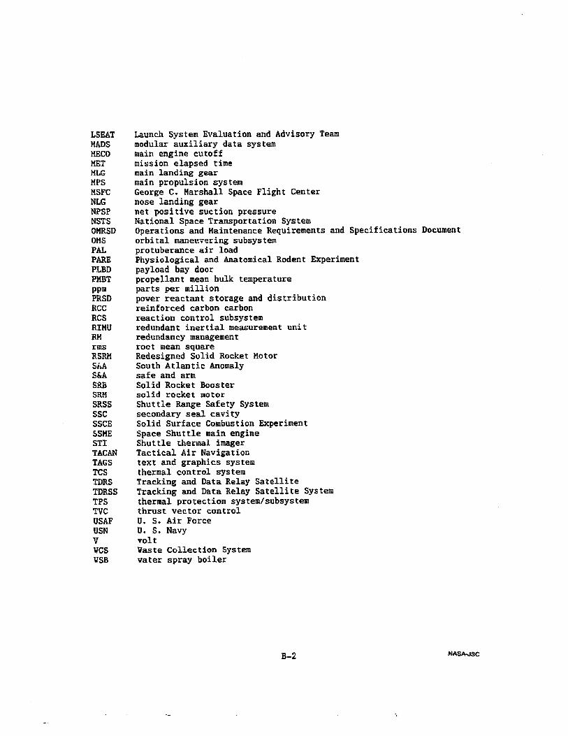
LSEATMADSMECOMETMLGMPSMSFCNLGNPSPNSTSOMRSDOMSPALPAREPLBDPMBTppmPRSDRCCRCSRIMURMrmsRSRMSi, A.S&ASRBSRMSRSSSSCSSCESSMESTITACANTAGSTCSTDRSTDRSSTPSTVCUSAFUSNVMCS{TSB
Launch System Evaluation and Advisory Teammodular auxiliary data systemmain engine cutoffmission elapsed timemain landing gearmain propulsion systemGeorge C. Marshall Space Flight Centernose landing gearnet positive suction pressureNational Space Transportation SystemOperations and Maintenance Requirements andorbital maneuvering subsystemprotuberance air loadPhysiological and Anatomical Rodent Experimentpayload bay doorpropellant mean bulk temperatureparts per millionpower reactant storage and distributionreinforced carbon carbonreaction control subsystemredundant inertial measurement unitredundancy managementroot mean squareRedesigned Solid Rocket MotorSouth Atlantic Anomalysafe and armSolid Rocket Boostersolid rocket motorShuttle Range Safety Systemsecondary seal cavitySolid Surface Combustion ExperimentSpace Shuttle main engineShuttle thermal imagerTactical Air Navigationtext and graphics systemthermal control systemTracking and Data Relay SatelliteTracking and Data Relay Satellite Systemthermal protection system/subsystemthrust vector controlU. S. Air ForceU. S. NavyvoltWaste Collection Systemwater spray boiler
Specifications Document
B-2
NASA-isc