article on the design of in-wheel-hub motor transmission
TRANSCRIPT

Article
On the Design of In-Wheel-Hub Motor Transmission Systems with Six-Link Mechanisms for Electric Vehicles Ngoc-Tan Hoang 1, Hong-Sen Yan 2,*
1 Department of Mechanical Engineering, National Cheng Kung University, 1 University Road, Tainan 70101, Taiwan; [email protected]
2 Department of Mechanical Engineering, National Cheng Kung University, 1 University Road, Tainan 70101, Taiwan; [email protected]
* Correspondence: [email protected]; Tel.: +886-093-951-5000
Abstract: Nowadays, there are several electric vehicle (EV) on the market, due to the innovation of technology that promotes the new components such as battery, transmission, electric motors. This paper proposes a design approach for the configuration synthesis and simulation of the in-wheel-hub motor transmissions with the six-link mechanisms. The synthesis process shows 6 mechanisms with six members and eight joints, 15 new clutchless motor transmissions and 16 new clutched motor transmissions. A novel motor transmission in the feasibility of the synthesized configurations is selected as an example to analyze the working principle with operation modes and power flow paths. And, this design is modeled for the simulation process that generates the results of operation mode transition and energy regulation.
Keywords: electric vehicles, configuration synthesis, motor transmission, in-wheel-hub motor, six-link mechanism.
1. Introduction
Many powertrain architectures have been designed and analyzed [1-10]. Yang et al. [11] compared fuel economy, emissions, and powertrain complexity of some popular electrified powertrains along with the conventional powertrain, and electric vehicle is one of the best choices with the highest fuel economy, zero emissions, and the lowest powertrain complexity, Figure 1.
Figure 1. Powertrain comparisons and reasons the EV market is growing
Preprints (www.preprints.org) | NOT PEER-REVIEWED | Posted: 24 July 2018 doi:10.20944/preprints201807.0442.v1
© 2018 by the author(s). Distributed under a Creative Commons CC BY license.

2 of 15
In 1998 , Weiss [12] proposed an electric wheel drive for a utility vehicle includes an electric motor with an output shaft that drives a final drive gearbox to reduce the rotational speed of the driven wheel. A transmission is arranged between the electric motor and the final drive gearbox, and it can be shifted between at least two rotational speed transmission ratios. The wheel drive permits attainment of a wide range of vehicle speeds with the use of low cost commercially available electric motors. The design speed of the electric motor corresponds with the principal operating speed of the vehicle, and relatively high vehicle speeds are possible.
Jing He et al. [13] took patents on the system that utilized multiple motors in 2012. The system employed a basic planetary gear train (PGT) as the transmission. The motor is connected to the ring gear, the flywheel is connected to the sun gear, and the output shaft to the carrier. The system comes up with a dual motor for increasing the power and operation modes. The system shows the combination of many motors to regulate energy for controlling series operation modes.
In 2014, Daisuke Gunji et al. [14] presents the wheel hub motor, which can fit inside a 16-inch wheel, incorporates two separate motors and a transmission consisting of two planetary gears that can deliver both high drive torque and high speeds. By controlling the speed and torque of the two motors, the transmission system provides smooth gear-changing, even during acceleration. In high gear operation, the two motors revolve in the same direction. When low gearing is needed, they revolve in opposite directions. Then, NSK company used this patent and improved on the real vehicle in 2017 [15]. It is now looking to commercialize specific components, including the wheel hub bearing with an integrated speed reducer, one-way clutch, and the wheel hub motor.
With the extension of Yan’s methodology for the systematic generation of new feasible configurations for HEVs [16, 17], Hoang and Yan synthesized feasible configurations of series-parallel hybrid transmissions with eight members and twelve joints [18]. Based on such a method, this study proposes an approach for the configuration synthesis and simulation of the in-wheel-hub motor transmissions with the six-link mechanisms, Figure 2.
Figure 2. The design process of motor transmissions.
Preprints (www.preprints.org) | NOT PEER-REVIEWED | Posted: 24 July 2018 doi:10.20944/preprints201807.0442.v1

3 of 15
2. Existing Motor Transmissions
Firstly, the existing designs of the motor transmission with six links and eight joints are identified and analyzed, including the design specifications and topological characteristics of existing designs, such as the numbers and types of links and joints, the adjacencies of links, and the diagram conversion.
2.1. Diagram conversions
By analyzing the existing design in reference [19], Figures 3(a), 3(b) and 3(c) show the schematic diagrams, block diagram and the corresponding generalized kinematic chain (GKC), respectively. Its topological characteristics are concluded as follows:
1. It is a compound PGT mechanism with 2-DoF, which is a combination of a simple PGT and a link.
2. It has six members including one ground link (member 1), one sun gear (member 2), one carrier (member 3), one planetary gear (member 4), one ring gear (member 5), and one additional link (member 6) that is connected with the carrier.
3. It has eight joints, consisting of five revolute joints (JR) and three gear joints (JG) including two external gear joints ( o
GJ ) and one internal gear joint ( iGJ ).
4. It has four links adjacent to the ground link.
RJRJ
RJRJ
oGJ
oGJ
RJiGJ
Figure 3. The motor transmission with six-link mechanism:
(a) Schematic diagram [19]; (b) Block diagram; (c) Corresponding GKC.
A planetary gear train with 2-DoF must satisfy the following expressions [16]:
2 4J LN N , (1)
1JR LN N , (2)
3JG LN N , (3)
where, NJ, NJR, NJG, and NL denote the numbers of joints, revolute joints, gear joints, and members, respectively.
The process of generalization transforms the schematic diagram of existing design, which includes various types of members and joints, into its block diagram and corresponding GKC based on a set of generalization rules [16]. The corresponding GKC shown in Figure 3(c) has six generalized links and eight generalized joints. According to the number synthesis of GKCs, there are nine GKCs for mechanisms with six members and eight joints as shown in Figure 4.
Preprints (www.preprints.org) | NOT PEER-REVIEWED | Posted: 24 July 2018 doi:10.20944/preprints201807.0442.v1

4 of 15
Figure 4. Generalized kinematic chains of six links and eight joints mechanisms.
2.2. Design constraints
Feasible specialized chains are identified from GKCs subject to the following design constraints, including mechanism constraints and input/output constraints.
Mechanism constraints
Ground link (member 1): 1. There must be one fixed link as the ground link. 2. The ground link must be a ternary link or quaternary link. Planet gear (member 4): 1. A planet gear must not be adjacent to the ground link. 2. There is no three-bar loop formed by any link adjacent to a planet gear, a binary link, and the
ground link. 3. Each planet gear must have just one carrier. Carrier (member 3):
The carrier is adjacent to all planet gears and the ground link (member 1) Sun gear, ring gear and remaining member(s) (members 2, 5, and 6): 1. There must be at least one sun (ring) gear in a PGT. 2. The sun (ring) gear must be adjacent to both the ground link and a planet gear. 3. Remaining member(s) can be adjacent to any link in the mechanism. Revolute joint (JR): 1. There must be five revolute joints. 2. The joints between a planet gear and its carrier, the ground link and a binary link must be revolute
joints. Gear pair (JG): 1. There must be three gear joints, including external gear joints ( o
GJ ) and internal gear joints
( iGJ ).
2. The joint between a planet gear and a ring (sun) gear must be a gear joint.
Inputs/output constraints
Output (O) 1. One member of compound PGT must be connected to the output shaft. 2. The output must be connected to a ring gear or planetary carrier of a PGT in order to achieve
high torque transfer when the motors drive the vehicle. 3. In the PGT set, the motor speed must be faster than the speed of the output shaft if the third link
is fixed. Motor 1 (M1) 1. One member of compound PGT must be connected to the motor shaft 1.
Preprints (www.preprints.org) | NOT PEER-REVIEWED | Posted: 24 July 2018 doi:10.20944/preprints201807.0442.v1

5 of 15
2. The motor 1 must be connected to a ring gear or a sun gear in order to achieve speed reduction and obtain higher torque at the output shaft.
3. The speed of motor 1 must be higher than the speed of motor 2. 4. The motor 1 must not be connected to a carrier in order to avoid excessive output speed. Motor 2 (M2) 1. One member of compound PGT must be connected to the motor shaft 2. 2. The motor 2 must be at least connected to a ring gear or planetary carrier in order to have high
efficiency when the vehicle is at high speed.
3. Feasible Mechanism Designs
From the nine available GKCs obtained above, only three GKCs with six links and eight joints satisfy the design constraints, as shown in Figures 4(d), (g) and (i). The corresponding GKCs subject to the design constraints above are identified according to the following steps:
1
62
4
53
1
62
4
35
1
65
4
23
1
4
1
Step 1
(g)
Step 2
(g1)
Step 3
Step 3
62
4
53
1
62
4
35
1
65
4
23
1
Step 4
Step 4
Step 4
(g2)
(g3)
(g4)
(g5)
RJRJRJ RJ
RJ
RJRJRJ RJ
RJ
RJRJRJ RJ
RJ
62
4
53
1
62
4
35
1
65
4
23
1
oGJi
GJ
RJRJRJ RJ
RJoGJ
RJRJRJ RJ
oGJ i
GJiGJ
RJ
RJRJRJ RJ
oGJ
RJ
iGJ
iGJ
Step 5 Step 6
Step 5 Step 6
Step 5 Step 6
(g6)
(g7)
(g8)
(g9)
(g10)
(g11)
Figure 5. Process of specialization.
Step 1: Assign the ground link (member 1). For each GKC, the ground link is assigned, as shown in Figure 5(g1).
Step 2: Assign the planet gear(s). For each result in Step 1, the planet gear(s) are assigned, as shown in Figure 5(g2).
Steps 3: Assign the carrier, the sun (ring) gear and the remaining member(s). For each result in Step 2, the carrier and the sun (ring) gear are assigned. At the end of this step, the remaining member(s) are also assigned, as shown in Figures 5(g3) to (g5).
Step 4: Assign the revolute joints (JR). For each result in Step 3, the revolute joints are assigned. Three results are generated, as shown in Figures 5(g6) to (g8).
Step 5: Assign the gear joints (JG). For each result in Step 4, the external and the internal gear joints (Jo
G and JiG) are assigned. As a result, three specialized chains are generated, as shown in Figures 5(g9)
to (g11). Step 6: Transfer specialized chains to block diagrams. For each result in Step 5, three specialized
chains are transferred to their corresponding block diagrams, as shown in Figures 5(g12) to (g14). Step 7: Transfer block diagrams to schematic diagrams. For each result in Step 6, three block diagrams
are transferred to their corresponding schematic diagrams, as shown in Figures 5(g15) to (g17).
Preprints (www.preprints.org) | NOT PEER-REVIEWED | Posted: 24 July 2018 doi:10.20944/preprints201807.0442.v1
6 of 15
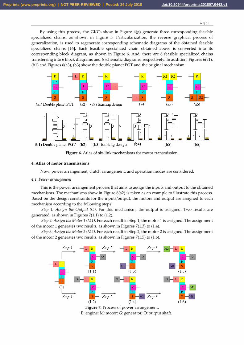
By using this process, the GKCs show in Figure 4(g) generate three corresponding feasible specialized chains, as shown in Figure 5. Particularization, the reverse graphical process of generalization, is used to regenerate corresponding schematic diagrams of the obtained feasible specialized chains [16]. Each feasible specialized chain obtained above is converted into its corresponding block diagram, as shown in Figure 6. And, there are 6 feasible specialized chains transferring into 6 block diagrams and 6 schematic diagrams, respectively. In addition, Figures 6(a1), (b1) and Figures 6(a3), (b3) show the double planet PGT and the original mechanism.
Figure 6. Atlas of six-link mechanisms for motor transmission.
4. Atlas of motor transmissions
Now, power arrangement, clutch arrangement, and operation modes are considered.
4.1. Power arrangement
This is the power arrangement process that aims to assign the inputs and output to the obtained mechanisms. The mechanisms show in Figure 6(a2) is taken as an example to illustrate this process. Based on the design constraints for the inputs/output, the motors and output are assigned to each mechanism according to the following steps:
Step 1: Assign the Output (O). For this mechanism, the output is assigned. Two results are generated, as shown in Figures 7(1.1) to (1.2).
Step 2: Assign the Motor 1 (M1). For each result in Step 1, the motor 1 is assigned. The assignment of the motor 1 generates two results, as shown in Figures 7(1.3) to (1.4).
Step 3: Assign the Motor 2 (M2). For each result in Step 2, the motor 2 is assigned. The assignment of the motor 2 generates two results, as shown in Figures 7(1.5) to (1.6).
Figure 7. Process of power arrangement.
E: engine; M: motor; G: generator; O: output shaft.
Preprints (www.preprints.org) | NOT PEER-REVIEWED | Posted: 24 July 2018 doi:10.20944/preprints201807.0442.v1

7 of 15
By applying this process to the other mechanisms, 15 systems with the identified the motor 1, the motor 2, and output are generated corresponding to the 6 obtained mechanisms. And, Figure 8 shows the atlas of motor transmission systems without clutch and brake.
Figure 8. Atlas of motor transmission systems without clutch.
E: engine; M: motor; G: generator; O: output shaft.
5.2. Clutch arrangement
Clutch arrangement is the process of assigning clutches and brakes to a system to control its operation modes subject to the required operation modes. It includes the steps of required operation modes and clutch arrangement.
a. Required operation modes Since the purpose of this work is to develop new motor transmission systems, the operation
modes of new systems are selected based on the vehicle operating conditions are presented by Mi et al. [20] as follows:
Motor 1 mode: the motor 1 alone drives the vehicle when the vehicle needs the high torque for begin running or climbing hill.
Motor 2 mode: when the power demand is moderately high (e.g., during highway cruise control), the transmission shifts to the motor 2 mode to further improve efficiency.
Combined power mode: when the power demand or required for heavy load or high-speed acceleration, the transmission shifts into power mode in which the motor 1 together with the motor 2 are turned on to provide additional power to drive the vehicle.
Regenerative braking mode: the electric motors is operated as a generator to convert kinetic energy from the vehicle’s braking process into electrical energy, which is stored in the battery.
b. Clutch arrangement
Based on the operation modes and status of power sources in each mode, the following process is used to add clutches and brakes to each system to achieve the required operation modes with the minimal number of clutches and brakes. The systems show in Figures 8(2) and (10) are taken as examples to illustrate the clutch arrangement process, as shown in Figure 9, respectively.
Step 1: M1 mode. Since motor 1 drive mode is required, the system is operated as a 1-DoF system while the motor 1 drives the vehicle. The addition of clutches and brakes generates each result, as shown in Figures 9(2.1) and (10.1).
Preprints (www.preprints.org) | NOT PEER-REVIEWED | Posted: 24 July 2018 doi:10.20944/preprints201807.0442.v1

8 of 15
Step 2: M2 mode. Since motor 2 drive mode is required, the system is still operated as a 1-DoF system while the motor 2 drives the vehicle. The addition of clutches and brakes generates each result, as shown in Figures 9(2.2) and (10.2).
Step 3: Combine mode. Both motors can be connected to the output shaft, and thus the systems become a 2-DoF as shown in Figures 9(2.3) and (10.3).
Figure 9. Process of clutch arrangement.
By applying this process to all systems, 16 clutched systems are synthesized for novel motor transmissions, as shown in Figure 10.
R
S
P2
P1C
M1
M2
O
R
S
P2
P1C
M1
O R1
S
R2
PC O
R1
S
R2
PC
O R1
S
R2
PC
O
M1
M2 R
S1PC
S2
O
M1 M2
R
S1PC
S2
O R
S1PC
S2M1
OM2 R
P
C
S
L
O
R
P
C
S
LO
R
P
C
SL
R
P
C
S
LO
R
P
C
SL
O
O
R
P
C
S
L
O
C3
B1
B2M2B2
C3
B1
OWC
OWC
OWC
C3
B1
B2
OWC
B1 B2
OWC
C3
B1
B2
OWC
C2
C1
C2
C1M1
M2
C3
B1
B2
C2
C1
M1
M2B2
C3
B1
C2
C1
C2
C1 C2C1
M1 M2
B1 B2
C2C1 C1
C2
M1
M2
C3
B1
B2
C2
C1M1
M2B2
C3
B1
C2
C1
M1
M2
C3
B1
C2
C1
B2
M1
M2
C3
B1
B2
C1
C2
M1
M2
C3
B1
B2
C2
C1M1
M2B2
C3
B1
C2
C1
R1
S
R2
PC O
M2M1B1 B2
OWC
C2C1
R
S1PC
S2
O
OWC
M1
M2
C3
B1
B2
C2
C1
(1) (2) (3) (4)
(5) (6) (7) (8)
(9) (10) (11) (12)
(13) (14) (15) (16) Figure 10. Atlas of novel motor transmissions.
Preprints (www.preprints.org) | NOT PEER-REVIEWED | Posted: 24 July 2018 doi:10.20944/preprints201807.0442.v1

9 of 15
5. Modeling
This section describes the modeling to identify the functions, the operation modes and the specifications for the simulation process including dynamic analysis and system specifications.
5.1 Dynamic analysis
To demonstrate the feasibility of the synthesized motor transmissions, the design shows in Figure 10(12) is selected as an example to show the operation modes and power flow analysis of the new system, Figure 11. The operation modes show in Figure 12, are divided into fifteen possible clutching conditions as listed in Table 1, where an “x” indicates that the corresponding brake or clutch is engaged.
B23
4
5
M1
M2
Wheel
B1
C1
C2
C3
12
6
Figure 11. A novel motor transmission.
Table 1. Operation modes and clutching conditions.
No. Operation mode Clutch and brake
engagement Reduction ratio
Remark C1 C2 C3 B1 B2
1 Motor 1-1 x x 3 Motor 1 alone drives the
wheel, while motor 2 idles 2 Motor 1-2 x 1.85 3 Motor 1-3 x x x 1 4 Motor 1-4 x x 1.35 5 Motor 2-1 x x 1
Motor 2 alone drives the wheel, while motor 1 idles
6 Motor 2-2 x 1.35 7 Motor 2-3 x x x 3 8 Motor 2-4 x x 1.85 9 Combined power 1 x x x 3
Motor 1 and motor 2 drive the wheel
10 Combined power 2 x x 1.85 11 Combined power 2 x x x 1 12 Combined power 4 x x 1.35 13 Combined power 5 x x 1.85 14 Regenerative braking 1 x x x 3 Motors work as a generator 15 Regenerative braking 2 x x 1.85
The relationship presented for torque and power provides the reference values of the power in
each operation mode. Then based on the power demand of the vehicle in a particular operation, the suitable operation mode is selected. Furthermore, with more clutches and brakes added to the systems, more operation modes can be performed to provide flexible control method for EVs during operation to further improve energy economy.
Preprints (www.preprints.org) | NOT PEER-REVIEWED | Posted: 24 July 2018 doi:10.20944/preprints201807.0442.v1

10 of 15
Figure 12. Operation modes of the novel motor transmission.
5.2 System Specifications
This section shows the required system specifications such as vehicle specifications, environment conditions, desired performances, and power sources specifications as shown in Table 2.
Table 2. System specifications.
Vehicle Motor 1 Weight (m) 1.550 kg Model Westinghouse 75
Frontal area (Af) 2.10 m2 Mass 91 kg Wheel radius (Rw) 0.325 m Type AC Induction Rolling resistance
coefficient (퐶 ) 0.02 Maximum Speed 10,000 rpm
Transmission efficiency (휂 )
0.95 Maximum power 55 kW
Driving environment Maximum torque 271 Nm Incline angle (휃) 0 degree Efficient region 3,000 – 10,000 rpm
Gravity (푔) 9.81 m/s2 Peak efficiency 92% Air mass density (휌) 1.225 kg/m3 Motor 2
Preprints (www.preprints.org) | NOT PEER-REVIEWED | Posted: 24 July 2018 doi:10.20944/preprints201807.0442.v1

11 of 15
Aerodynamic drag coefficient (퐶 )
0.33 N*s2/kg*m Model Prius Japan
Performance Mass 76 kg Maximum speed 200 km/h Type AC Induction Acceleration time 9 s Maximum Speed 6,000 rpm
Grade ability 32% Maximum power 75 kW Battery Maximum torque 322 Nm
Model MY 2016 S lithium-ion battery Efficient region 2000 – 6000 rpm
Max capacity (퐶 ) 85 kWh Peak efficiency 90%
6. Simulation
This part describes the computer simulation of the novel motor transmission built with MATLAB/SIMULINK.
6.1 Simulation structure
The simulation model is developed, as shown in Figure 13, including drive cycle, driving force calculation, control logic, power sources system, transmission, and wheel system. The simulation results of the novel design are regarded to the two driving cysles are the Urban Dynamometer Driving Schedule (UDDS) and the Highway Fuel Economy Test (HWFET), as the two most popular cycles for automotive manufacturers.
Figure 13. The simulation structure.
6.2 Control parameters
According to the actual vehicle speed, a feasible gear is selected through the gear determination process. According to the obtained reduction ratio and the required driving force, the minimum energy consumption of each 1-DoF operation mode is calculated. With the predicted energy consumptions and the vehicle driving conditions, the mode determination process is gone through to select the most suitable operation mode. Finally, the optimized torque demands for the power sources and the clutching signal are output.
In gear determination process, the gear is selected to maintain the motors operating within high-efficiency region; therefore, the suitable reduction ratio at that instant is obtained. Figure 14 shows the gear determination criterion. When the vehicle stops and the required driving force is zero, the gear state is 0; otherwise, the gear state is a positive integer. To maintain high motors efficiency, the gear state changes when the vehicle speed achieves the threshold speeds of each gear.
Preprints (www.preprints.org) | NOT PEER-REVIEWED | Posted: 24 July 2018 doi:10.20944/preprints201807.0442.v1

12 of 15
Figure 14. The gear determination control.
In mode determination process, three basic states, including parking state, driving state and regenerative braking state are defined, as shown in Figure 15. In each state, the corresponding operation mode is available. When the vehicle is stop, the vehicle shifts to parking state. When the vehicle is moving but not braking, the mode state shifts to driving. When the vehicle torque demand is negative, the regenerative braking mode is selected.
In both driving states, the vehicle starts with the motors mode. According to the feasible mode shifts obtained by shifting analysis, the mode shifts among the modes in the same gear are always feasible. Therefore, the operation mode is selected totally according to the predicted energy consumptions when the vehicle exits starting phase and enters normal phase of the two driving state.
Figure 15. The stateflow chart of mode determination control.
6.3 Simulation results
The simulation results of the novel design regarding to the two driving cycles are shown in Figure 16. The results evaluate the conversion of gear states, operation modes, and energy consumption in the urban driving condition and the latter represents the highway driving condition.
Preprints (www.preprints.org) | NOT PEER-REVIEWED | Posted: 24 July 2018 doi:10.20944/preprints201807.0442.v1

13 of 15
UDDS
HWFET
Figure 16. The simulation results of UDDS and HWFET
Table 3 and Figure 17 present the comparison of operation modes selection between UDDS and HWFET. The time and percentage of operation modes hold in the driving cycles pointed out that the results are reasonable.
Table 3. The comparison of operation mode selection between UDDS and HWFET.
Operation modes Time (s) Percentage (%) UDDS HWFET UDDS HWFET
1. Parking 330 18 27 1 2. Motor 1 122 110 10 9 3. Motor 2 73 36 6 3 4. Combined power 390 891 32 73 5. Regenerative braking 305 165 25 14
Total 1220 100
Figure 17. The comparison of operation mode selection between UDDS and HWFET.
7. Conclusions
A design procedure is proposed and illustrated based on the extension of the creative mechanism design methodology to synthesize the feasible mechanisms for the configurations of motor transmissions. By using the techniques of power arrangement and clutch arrangement, the
Preprints (www.preprints.org) | NOT PEER-REVIEWED | Posted: 24 July 2018 doi:10.20944/preprints201807.0442.v1

14 of 15
mechanisms are used for synthesizing clutchless and clutched motor transmissions. As a result, 6 compound PGTs are systematically synthesized for hybrid transmission by using the creative design techniques, and 15 clutchless and 16 clutched motor transmissions are synthesized. The design constraints and desired operation modes decide the number of mechanisms and motor transmissions. Since some of the operation modes are required and some of them are flexible choices of engineers, systems with different characteristics can be generated.
After analyzing a novel motor transmission system, a computer simulation model is constructed to evaluate the translation of the operation modes in the UDDS and HWFET driving cysles. With this design approach, many motor transmissions can be synthesized, analyzed and simulated to find the atlas of the best motor transmissions.
Acknowledgments: This work was supported by the Ministry of Science and Technology (Taiwan, R.O.C.) under Grant MOST 104-2221-E-006-059-MY3.
Author Contributions: The paper was a collaborative effort between the authors. The authors contributed collectively to the theoretical analysis, design, synthesis, and manuscript preparation.
Conflicts of Interest: The authors declare no conflict of interest.
References
1. Berman, B., Gelb, G.H., Richardson, N.A., Wang, T.C. Power Train using Multiple Power Sources. U.S. Patent 3566717, 2 March 1971.
2. Hata, H.; Kojima, M.; Adachi, M.; Shimizu, T. Power Transmission System. U.S. Patent 7081060, 20 September 2006.
3. Schmidt, M. R. Two-Mode, Compound-Split, Electro-Mechanical, Vehicular Transmission. U.S. Patent 5558589, 1996.
4. Zhang, D., Chen, J., Hsieh, J., Rancourt, J., Schmidt, M.R. Dynamic modeling and simulation of two-mode electric variable transmission. Proc. Inst. Mech. Eng. Part D J. Automob. Eng. 2001, 215, 1217–1223.
5. Ai, X., Mohr, T., and Anderson, S. An Electromechanical Infinitely Variable Speed Transmission. Soc. Automotive Eng. World Congr. Exh., Detroit, MI, SAE Paper 2004-01-0354.
6. Villeneuve, A. Dual Mode Electric Infinitely Variable Transmission. Proc. of the SAE, March 8- 2004, Detroit, MI, pp. 1-11.
7. Ai, X., and Mohr, T. W. Output-Split and Compound-Split Infinitely Variable Transmission. U.S Patent 6964627, 2005.
8. Hoeijmakers, M. J. The Electric Variable Transmission. IEEE Trans. Ind. Appl. 2006, vol. 42, no. 4, pp. 1092-1100.
9. Turnbull, P., F., Conlon, B., M., Holmes, A., G. Electrically Variable Transmission. U.S. Patent 8585520, 2013.
10. Zhang X, Li SE, Peng H, Sun J. Efficient exhaustive search of power-split hybrid powertrains with multiple planetary gears and clutches. Journal of Dynamic Systems, Measurement, and Control 2015;137(12):121006.
11. Yinye, Yang., et al. State-of-the-art electrified powertrains-hybrid, plug-in, and electric vehicles. Int. j. Powertrains, 2016, Vol. 5, No.1.
12. Heinz Weiss et al. Electric wheel drive for a utility vehicle. U.S. Patent 005813488, 1998. 13. Jing He et al. Powertrain and method for a kinetic hybrid vehicle. U.S. Patent 0196713, 2012. 14. Daisuke Gunji et al. Wheel hub motor. U.S. Patent 008758178, 2014. 15. NSK’s website: http://www.nsk.com/company/news/2017/press0119a.html 16. Yan, H.S. Creative Design of Mechanical Devices; Springer-Verlag: Berlin, Germany, 1998. 17. Ngo, H.T.; Yan, H.S. Configuration synthesis of series-parallel hybrid transmission. Inst. Mech.
Eng. 2015, 230, 664–678. 18. Hoang, N.T.; Yan, H.S. Configuration Synthesis of Novel Series-Parallel Hybrid Transmission
Preprints (www.preprints.org) | NOT PEER-REVIEWED | Posted: 24 July 2018 doi:10.20944/preprints201807.0442.v1

15 of 15
Systems with Eight-Bar Mechanisms. Energies 2017, 10, 1044. 19. Kima., et al. Control device for in-wheel transmissions in an electric vehicle. U.S. Patent 0023791,
2002. 20. Mi, C.; Masrur, M.; Gao, W.Z. Hybrid Electric Vehicle: Principles and Applications with Practical
Perspectives; John Wiley & Sons: Hoboken, NJ, USA, 2011.
Preprints (www.preprints.org) | NOT PEER-REVIEWED | Posted: 24 July 2018 doi:10.20944/preprints201807.0442.v1