article in press - walter scott, jr. college of …lqyang/publist/oxby08.pdf · article in press 2...
TRANSCRIPT

ARTICLE IN PRESSPhysical Communication ( ) –
Contents lists available at ScienceDirect
Physical Communication
journal homepage: www.elsevier.com/locate/phycom
Full length article
Orthogonal bi-pulse UWB: Timing and (de)modulationMourad Ouertani a,d, Huilin Xu b, Hichem Besbes c, Liuqing Yang b,∗, Ammar Bouallègue da Institut Supérieur d’Informatique, ISI, Tunisiab Department of Electrical & Computer Engr., University of Florida, Gainesville, FL 32601, United Statesc Research Unit TECHTRA, Ecole Supérieure des Communications de Tunis, Sup’Com, Tunisiad Laboratoire SysCom, Ecole Nationale d’Ingénieurs de Tunis, ENIT, Tunisia
a r t i c l e i n f o
Keywords:Ultra-widebandOrthogonal pulseSynchronizationDemodulationNoncoherent
a b s t r a c t
In this paper,wepropose a novel orthogonal bi-pulse ultra-wideband (UWB) system,whichuses an even pulse and an odd pulse to convey information symbols in an alternatingmanner. Due to the orthogonality of these pulses, their corresponding received waveformsremain orthogonal after propagating through multipath channels. Then we consider twomajor challenges in the realization of our proposed UWB system: timing synchronizationand symbol demodulation. In particular, the idea of timing with dirty template (TDT)in [L. Yang, G.B. Giannakis, Timing Ultra-Wideband signals with dirty templates, IEEETrans. on Commun. 53 (11) (2005) 1952–1963] is employed for timing synchronizationand the noncoherent scheme in [L. Yang, G.B. Giannakis, A. Swami, Noncoherent Ultra-Wideband (de)modulation, IEEE Trans. Commun. 55 (4) (2007) 810–819] is used to bypasschannel estimation. Both of these techniques are characterized by correlating adjacentwaveform segments. In the implementation of these techniques, we will gradually revealthe advantages of our proposed system. The correlation of adjacent waveform segmentsonly contains the information of a single symbol. This enables a significant enhancementof the synchronization speed of TDTwhenno training sequence is transmitted. For the samereason, our demodulation approach completely mitigates the inter-symbol interference(ISI) in the second paper referred to, above, and entails a simple demodulator even in thepresence of unknown timing errors. Simulations are also carried out to corroborate ouranalysis.
© 2008 Elsevier B.V. All rights reserved.
1. Introduction
Ultra-Wideband (UWB) impulse radios (IR) are carrier-less systems, based on the transmission of pulses withvery short duration. Due to its huge bandwidth andlow power, IR can potentially provide high data-ratetransmission in short-range applications,without inducingstrong interferences to legacy wireless systems.
∗ Corresponding address: Department of Electrical & Computer En-gineering, University of Florida, P.O.Box 116130, 32601 Gainesville, FL,United States. Tel.: +1 352 392 9469; fax: +1 352 392 0044.E-mail addresses: [email protected] (M. Ouertani),
[email protected] (H. Xu), [email protected] (H. Besbes),[email protected] (L. Yang), [email protected](A. Bouallègue).
Pulse-shape modulation (PSM) has been proposed forUWB IR as a supplement to the traditional pulse-amplitudemodulation (PAM) and pulse-position modulation (PPM).By using multiple orthogonal pulses for informationtransmission, PSM can improve the spectral efficiencywhen jointly deployed with PAM and PPM (see e.g., [3–5]).In this paper, instead of using multiple pulses for data-rate enhancement, we adopt a pair of orthogonal pulses,an odd waveform and an even waveform, for UWB IRsystems to facilitate faster timing synchronization andlower-complexity demodulation.Timing synchronization is a major challenge in UWB
systems (see [6] and the references therein). In [1], tim-ing with dirty template (TDT) was developed for fast syn-chronization of UWB signals. This technique relies on
1874-4907/$ – see front matter© 2008 Elsevier B.V. All rights reserved.doi:10.1016/j.phycom.2008.10.001
Please cite this article in press as: M. Ouertani, et al., Orthogonal bi-pulse UWB: Timing and (de)modulation, Physical Communication (2008),doi:10.1016/j.phycom.2008.10.001

ARTICLE IN PRESS2 M. Ouertani et al. / Physical Communication ( ) –
correlating adjacent symbol-long segments of the receivedwaveform. TDT is operational with arbitrary and unknowntransmitted symbol sequences. When training symbols(pilots) are affordable, the performance of the TDT syn-chronizer can be improved by adopting a data-aided (DA)mode [1]. The DAmode considerably outperforms the non-data-aided (NDA) one. However, the training sequence en-tails an overheadwhich reduces the bandwidth and energyefficiency.In this paper, we apply the concept of TDT to our
proposed orthogonal bi-pulse UWB IR. Similar to theoriginal TDT [1], our timing algorithm also relies oncorrelating adjacent waveform segments. In particular,a synchronization will be asserted when the correlationfunction reaches its maximum. Due to the employment oforthogonal pulses, the bi-pulse based TDT can avoid therandom symbol effect of the original NDA TDT. Therefore,the bi-pulse TDT can improve the synchronization speedand simultaneously preserve the energy efficiency by onlyslightly increasing the transceiver complexity.Due to the extremely rich multipath of UWB channels,
channel estimation becomes another big challenge in therealization of the optimal coherent receiver, i.e. the RAKEreceiver. Therefore, alternative techniques have been pro-posed to bypass the explicit channel estimation. These in-clude the transmitted reference (TR) technique [10] whichdemodulates by correlating the receivedwaveform of eachinformation-bearing symbol with that of an associating pi-lot symbol, and the differential UWB [11] which corre-lates the consecutive differentially modulated waveformpair. Operations of these systems require different levels oftiming synchronization. However, performance of both de-grades when timing error is present. This is because mist-iming induces inter-symbol interference (ISI), while themethods in [10,11] both ignore the ISI. Instead of ignor-ing the ISI, a noncoherent approach is proposed in [2] toexplicitly deal with the ISI using Viterbi algorithm, so thatmaximum likelihood (ML) demodulation of differentiallymodulatedUWBsignals becomespossible even in the pres-ence of unknown timing errors.In this paper, we also employ the noncoherent demod-
ulation algorithm for the orthogonal bi-pulse UWB IR. Atthe receiver, we use the correlation between neighboringwaveform segments for demodulation. Similar to TR UWBand other techniques, our approach remains operationalwhen channel estimation is bypassed. In addition, by usingorthogonal pulses, our noncoherent algorithm completelyavoids ISI even in the presence of timing errors. As a re-sult, our algorithms only entail a very simple demodulator,while retaining the ML optimality.Both the timing synchronization and symbol demod-
ulation can be realized in a framework characterized bythe extraction and correlation of symbol-level waveforms.Thanks to our novel use of the orthogonal pulse pair, bothalgorithms can be realized in amore effectivemanner thanthe original IR. The rest of this paper is organized as follows.Section 2 describes the bi-pulse UWB IR system model. InSections 3 and 4, the timing and demodulation algorithmsare introduced, respectively. In Section 5, simulations arecarried out to corroborate our analysis. Conclusions aregiven in Section 6.
2. Bi-pulse UWB impulse radio
In this section, wewill first introduce the systemmodelfor conventional UWB IRs. Then, wewill extend this modelto a bi-pulse IR system by replacing the single pulse shaperwith a pair of orthogonal pulses.
2.1. Conventional UWB impulse radio
Let us consider an IR UWB system, where eachinformation symbol is transmitted over a Ts period thatconsists of Nf frames. During each frame of duration Tf ,a data-modulated pulse p(t) with duration Tp � Tf istransmitted from the antenna. The transmitted signal is
v(t) =√
E∞∑n=0
s(n) · pT (t − nTs) (1)
where E is the energy per pulse, s(n) := s(n)s(n − 1)are differentially encoded symbols with s(n) denoting thebinary PAM information symbols and pT (t) denotes thesymbol-level transmitted waveform:
pT (t) =Nf−1∑n=0
cds(n) · p(t − nTf − cth(n)Tc) (2)
where Tc is the chip duration. Notice that pT (t) can beregarded as the symbol-level pulse shaper which accountsfor the time-hopping (TH) and/or direct-sequence (DS)spreading via cth(n) and cds(n), respectively.The transmitted signal propagates through the multi-
path channel with impulse response
g(t) =L−1∑l=0
αlδ(t − τl) (3)
where {αl}l=L−1l=0 and {τl}l=L−1l=0 are amplitudes and delays ofthe Lmultipath elements, respectively. Among {τl}l=L−1l=0 , τ0represents the propagation delay of the channel.Then, the received waveform is given by
r(t) =√
E∞∑n=0
s(n) · pR(t − nTs − τ0 + τr)+ η(t) (4)
where η(t) is the additive noise, τr is arbitrary reference atthe receiver and pR(t) denotes the aggregate symbol-levelreceived waveform:
pR(t) =Nf−1∑n=0
cds(n) · p(t − nTf − cth(n)Tc) ∗ g(t + τ0) (5)
where ∗ denotes the convolution operation.1 Let us define1τ := τr − τ0 as the timing offset. Without loss ofgenerality, we assume that1τ is in the range of [0, Ts). Aswe will show in the rest of this paper, this assumption willnot affect the timing synchronization and the differentialdemodulation.
1 Due to the distortion effects of transmit and receive antennas, thereceive pulse shaper could be different from p(t) [18]. However, this willnot affect the design and operation of our bi-pulse timing synchronizerand demodulator in this paper.
Please cite this article in press as: M. Ouertani, et al., Orthogonal bi-pulse UWB: Timing and (de)modulation, Physical Communication (2008),doi:10.1016/j.phycom.2008.10.001

ARTICLE IN PRESSM. Ouertani et al. / Physical Communication ( ) – 3
Fig. 1. Transmittedwaveforms using orthogonalmodulation scheme andthe TH code [0, 1, 0].
2.2. Bi-pulse IR system model
In our system, every encoded information symbol isstill transmitted over a Ts duration. However, each symbolduration is divided into two equal halves. The two halveswill use a pair of pulse shapers: an even waveform p0(t)and an odd waveform p1(t). The even and odd pulses canbe chosen as Gaussian pulses [7], Hermite pulses [13], ortheir derivatives. The optimal design of these pulses hasbeen widely investigated in the literature (see e.g., [8,9]).For the symbol with an even index, the pulse p0(t) is
data-modulated and transmitted in the first half of thesymbol duration and pulse p1(t) in the second half. For thesymbol with an odd index, p1(t) is used for the former halfand p0(t) for the latter half of the symbol duration (seeFig. 1). For this approach, we use the same time-hoppingand spreading codes for the two halves, i.e., cth(i) =cth(Nf /2+ i) and cds(i) = cds(Nf /2+ i), i ∈ [0,Nf /2− 1].Denote the symbol-level transmittedwaveformwith an
even index by pT0(t) and by pT1(t) otherwise. The receivedsignal is given by:
r(t) =√
E∞∑n=0
s (n) · pRin(t − nTs +1τ)+ η(t) (6)
where pRin(t) is the noise-free received symbol-levelwaveform with in = [n]2. Here we use [A]B for the modulooperation with base B. To facilitate the noncoherent UWBdemodulation, we select Tf and the TH code of the (Nf /2−1)st frame to satisfy (cth(Nf /2 − 1)Tc + Tp + τL−1) <Tf so that there is no interference between the even andodd waveforms (p0(t) and p1(t)) even after multipathpropagation. However, it isworth noting that no constraintis imposed on the inter-frame interference and inter-pulse interference within each Ts/2 duration exclusivelycontaining p0(t) or p1(t). Then, we can express pR0(t) andpR1(t) as follows:
pR0(t) =
R0(t) if t ∈
[0,Ts2
)R1
(t −Ts2
)if t ∈
[Ts2, Ts
)
pR1(t) =
R1(t) if t ∈
[0,Ts2
)R0
(t −Ts2
)if t ∈
[Ts2, Ts
)(7)
where
R0(t) =Nf /2−1∑n=0
cds(n) · p0(t − nTf − cth(n)Tc) ∗ g(t + τ0)
and
R1(t) =Nf /2−1∑n=0
cds(n) · p1(t − nTf − cth(n)Tc) ∗ g(t + τ0)
denote the parts of symbol-level waveforms involvingp0(t) and p1(t), respectively.For illustrative purpose, Ri(t) is plotted in Fig. 2 as a
triangle with the maximum non-zero support of Ts/2 andthe frame-level repetition is ignored. Notice that due tothe timing error, every Ri(t) can be partitioned into twosegments qai (t,1τ) and q
bi (t,1τ) (see Fig. 2):
qai (t,1τ) =
0, t ∈
[0,Ts2− [1τ ]Ts/2
)Ri
(t −Ts2+ [1τ ]Ts/2
),
t ∈[Ts2− [1τ ]Ts/2 ,
Ts2
) (8)
and
qbi (t,1τ) =
Ri(t + [1τ ]Ts/2),
t ∈[0,Ts2− [1τ ]Ts/2
)0, t ∈
[Ts2− [1τ ]Ts/2 ,
Ts2
).
(9)
The waveforms qai (t,1τ) and qbi (t,1τ) constitute the
complete waveform Ri(t) as:
Ri(t) = qai(t + Ts/2− [1τ ]Ts/2,1τ
)+ qbi
(t − [1τ ]Ts/2,1τ
). (10)
Timing synchronization and channel estimation are twomajor challenges for the realization of UWB IR. In thenext two sections, we will discuss how to address theseproblems for our proposed orthogonal bi-pulse UWB IRsystem.
3. Timing Bi-pulse UWB signals
In this section, we will derive an NDA timing synchro-nizer based on the orthogonal bi-pulse UWB system. Fol-lowing the idea of TDT [1], our timing algorithm also relieson correlating the neighboring signal segments. Instead oftaking Ts-long segments, however, TDT for bi-pulse IR re-lies on half-symbol (Ts/2)-long segments of the receivedwaveform.Our demodulation starts with extracting the Ts/2-long
segments from the receivedwaveform. These segments aregiven by:
rn(t) = r(t + nTs)rn(t + Ts/2) = r(t + nTs + Ts/2)
, t ∈ [0, Ts/2). (11)
Please cite this article in press as: M. Ouertani, et al., Orthogonal bi-pulse UWB: Timing and (de)modulation, Physical Communication (2008),doi:10.1016/j.phycom.2008.10.001

ARTICLE IN PRESS4 M. Ouertani et al. / Physical Communication ( ) –
Fig. 2. The Ts/2-long signal segments.
Then, adjacent segments are correlated to calculate thecorrelation function x(n,1τ):
x(n,1τ) =∫ Ts
2
0rn(t)rn
(t −Ts2
)dt. (12)
The next question is how to recover the timing offset 1τfrom this correlation function.Let us first introduce two Lemmaswhichwill be used to
derive the timing algorithm from Eq. (12).
Lemma 1. Let p0(t) and p1(t) constitute an even and oddpulse pair. After propagating through any real channel, thereceived waveforms corresponding to p0(t) and p1(t) are stillorthogonal.
Proof. See Appendix. �
Lemma 1 implies that∫ Ts2
0qα0 (t,1τ)q
α1 (t,1τ)dt = 0, α ∈ {a, b}.
In addition, since the non-zero supports of qai (t,1τ)and qbi (t,1τ) do not overlap, the following always holdstrue:
Lemma 2. When the non-zero support of Ri(t) is upperbounded by Ts/2, we have∫ Ts
2
0qai (t,1τ)q
bi (t,1τ)dt = 0, i ∈ {0, 1}. (13)
This is evident from Eqs. (8) and (9).With these results, we are ready to recover the timing
error1τ from the correlation function x(n,1τ) in Eq. (12).Using Lemmas 1 and 2, x(n,1τ) can be expressed in a verysimple form which contains the energy of either qai (t) orqbi (t), i ∈ {0, 1}, depending on whether 1τ ∈ [0, Ts/2) or1τ ∈ [Ts/2, Ts).
3.1. Case I:1τ ∈ [0, Ts/2)
In this case, the noise-free signal segments involved intiming synchronization are [cf. (6) and (11)]
rn(t − Ts/2) = s(n− 1)qbi (t,1τ)+ s(n)qai (t,1τ)
rn(t) = s(n)qbi (t,1τ)+ s(n)qaj (t,1τ),
i 6= j ∈ {0, 1} (14)
where rn(t − Ts/2) and rn(t) are the noise-free partsof rn(t − Ts/2) and rn(t), respectively. As a result, thenoise free part of the correlation function x(n,1τ) can beexpressed as [cf. (12)]:
x(n,1τ) =∫ Ts
2
0
(s(n− 1)qbi (t,1τ)+ s(n)q
ai (t,1τ)
)×(s(n)qbi (t,1τ)+ s(n)q
aj (t,1τ)
)dt. (15)
Using Lemmas 1 and 2, and the differential modulationrelationship, x(n,1τ) becomes:
x(n,1τ) =∫ Ts
2
0sn(qbi (t,1τ))
2dt. (16)
Accordingly, the absolute value of x(n,1τ) can beequivalently expressed as:
|x(n,1τ)| =∫ Ts
2
0
(qbi (t,1τ)
)2dt := Eb(1τ) (17)
where Eb(1τ) is defined as the energy of the waveformsegment qbi (t,1τ). In the random channel environment,it is reasonable to assume that qb0(t,1τ) and q
b1(t,1τ)
approximately have the same energy Eb(1τ). It should benoted that Eb(1τ) decreases as 1τ increases (see Fig. 2).Therefore, we have the following result:
Proposition 1. For the orthogonal bi-pulse UWB IR system,when the timing error 1τ is in the range of [0, Ts/2),the absolute value of the noise-free correlation function|x(n,1τ)| equals the energy Eb(1τ) of the waveformsegment qbi (t,1τ), which is a decreasing function in1τ .
Notice that Eq. (17) shows that |x(n,1τ)| is a constantindependent of the symbol index n, even when a random
Please cite this article in press as: M. Ouertani, et al., Orthogonal bi-pulse UWB: Timing and (de)modulation, Physical Communication (2008),doi:10.1016/j.phycom.2008.10.001

ARTICLE IN PRESSM. Ouertani et al. / Physical Communication ( ) – 5
symbol sequence is transmitted. This consists of a funda-mental difference between our method here and the origi-nal TDT in [1], where the correlator output varies with theparticular symbol sequence transmitted. As a result, unlikethe original TDT in [1] that entails significant averaging orspecial training patterns to remove the random symbol ef-fect, our approach here completely avoids such a problem.
3.2. Case II:1τ ∈ [Ts/2, Ts)
In this case, the noise-free signal segments involved intiming are [cf. (6) and (11)]
rn(t − Ts/2) = s(n)qbi (t,1τ)+ s(n)qaj (t,1τ)
rn(t) = s(n)qbj (t,1τ)+ s(n+ 1)qaj (t,1τ),
i 6= j ∈ {0, 1}. (18)
The noise-free correlation function can be expressed as[cf. (12)]:
x(n,1τ) =∫ Ts
0
(s(n)qbi (t,1τ)+ s(n)q
aj (t,1τ)
)×(s(n)qbj (t,1τ)+ s(n+ 1)q
aj (t,1τ)
)dt. (19)
Using Lemmas 1 and 2, x(n,1τ) becomes:
x(n,1τ) =∫ Ts
2
0sn+1(qaj (t,1τ))
2dt. (20)
Accordingly, the absolute value of x(n,1τ) can beequivalently expressed as:
|x(n,1τ)| =∫ Ts
2
0
(qaj (t,1τ)
)2 dt := Ea(1τ) (21)
where Ea(1τ) is the energy of waveform segmentqaj (t,1τ), j ∈ {0, 1}. Since Ea(1τ) increases as 1τincreases (see Fig. 2), we have the following result:
Proposition 2. For the orthogonal bi-pulse UWB IR system,when the timing error 1τ is in the range of [Ts/2, Ts),the absolute value of the noise-free correlation function|x(n,1τ)| equals the energy Ea(1τ) of the waveformsegment qaj (t,1τ), which is an increasing function in1τ .
Notice that here |x(n,1τ)| also remains a constant ∀n,at any given 1τ . This again confirms that the randomsymbol effect is completely mitigated in our bi-pulse IRapproach.
3.3. TDT for Bi-pulse IR
Generally, it is unknown to the receiver whether 1τis in [0, Ts/2) or in [Ts/2, Ts). However, we notice thatfor 1τ ∈ [0, Ts/2), |x(n,1τ)| = Eb(1τ) increasinglyapproaches its maximum Eb(0) = ER when 1τapproaches 0; it also decreasingly approaches itsminimumEb(Ts/2) = 0 when 1τ approaches Ts/2 (see Fig. 2).In addition, for 1τ ∈ [Ts/2, Ts), |x(n,1τ)| = Ea(1τ)decreasingly approaches its minimum Ea(Ts/2) = 0when1τ approaches Ts/2 and increasingly approaches itsmaximum Ea(Ts) = ER when1τ approaches Ts. Therefore,
|x(n,1τ)| is continuous at 1τ = Ts/2. Moreover,|x(n,1τ)| is a periodic function of 1τ with period of Ts;that is, |x(n,1τ)| = |x(n, Ts + 1τ)|,∀1τ . Therefore,|x(n,1τ)| reaches its minimum when 1τ = Ts/2, andreaches its maximum when 1τ = 0. This result leads toa timing synchronizer based on the sample mean of thesymbol-rate samples |x(n,1τ)|.In the following, we combine Propositions 1 and 2 to
build a timing synchronizer for our proposed bi-pulse IRsystem:
Proposition 3. For the orthogonal bi-pulse IR system, a blindtiming synchronizer can be built even when TH codes arepresent and the UWB multipath channel is unknown. Thetiming algorithm can be summarized in the following steps:
Step 1: Extract the Ts/2-long segments r(t + nTs) and r(t +nTs − Ts/2) from the received waveform.
Step 2: Estimate the noise-free correlation function of adja-cent segments with
y(M,1τ) =1M
×
M∑n=1
∣∣∣∣∣∫ Ts
2
0r(t + nTs)r(t + nTs − Ts/2)dt
∣∣∣∣∣ .Step 3: The timing error can be estimated when y(M,1τ)
reaches its maximum
1τ = arg max1τ∈[0,Ts)
y(M,1τ).
Unlike the original NDA TDT, the estimation of the cor-relation function for our synchronizer is not affected bythe ISI (see Eqs. (17) and (21)) even with random infor-mation symbols. Therefore, the proposed synchronizationapproach is expected to achieve a better acquisition per-formance than that of the original TDT in the NDA mode(see Fig. 3).
4. Demodulating Bi-pulse UWB signals
Following the noncoherent UWB [12], our demodu-lation also builds on correlating the neighboring signalsegments. The advantage is that due to the orthogonalitybetween p0(t) and p1(t), our algorithm avoids ISI even inthe presence of mistiming. The demodulation algorithmalso starts from the extraction and correlation of Ts/2-longwaveform segments. The extraction is as described in thepreceding section. However, the correlation is carried outin a different manner, as detailed in the following.
4.1. Extraction of decision statistics
Instead of x(n,1τ), we calculate two correlationfunctions x1(n,1τ) and x2(n,1τ) (see Fig. 4):
x1(n,1τ) =∫ Ts
2
0rn(t)rn−1
(t +Ts2
)dt
+
∫ Ts2
0rn
(t +Ts2
)rn−1(t)dt (22)
Please cite this article in press as: M. Ouertani, et al., Orthogonal bi-pulse UWB: Timing and (de)modulation, Physical Communication (2008),doi:10.1016/j.phycom.2008.10.001
ARTICLE IN PRESS6 M. Ouertani et al. / Physical Communication ( ) –
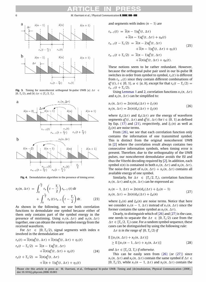
Fig. 3. Timing for noncoherent orthogonal bi-pulse UWB (a) 1τ ∈[0, Ts/2), and (b)1τ ∈ [Ts/2, Ts).
Fig. 4. Demodulation algorithm in the presence of timing error.
x2(n,1τ) =∫ Ts
2
0rn
(t −Ts2
)rn−1 (t) dt
+
∫ Ts2
0rn (t) rn−1
(t −Ts2
)dt. (23)
As shown in the following, we use both correlationfunctions to demodulate one symbol because either ofthem only contains part of the symbol energy in thepresence of mistiming. Using x1(n,1τ) and x2(n,1τ)together, one can obtain the entire symbol energy from thereceived waveform.For 1τ ∈ [0, Ts/2), signal segments with index n
involved in the demodulation are
rn(t) = s(n)qbi (t,1τ)+ s(n)qaj (t,1τ)+ η1(t)
rn(t − Ts/2) = s(n− 1)qbi (t,1τ)+ s(n)qai (t,1τ)+ η2(t)
rn(t + Ts/2) = s(n)qbj (t,1τ)
+ s(n+ 1)qaj (t,1τ)+ η3(t)
(24)
and segments with index (n− 1) are
rn−1(t) = s(n− 1)qbj (t,1τ)
+ s(n− 1)qai (t,1τ)+ η4(t)
rn−1(t − Ts/2) = s(n− 2)qbj (t,1τ)
+ s(n− 1)qaj (t,1τ)+ η5(t)
rn−1(t + Ts/2) = s(n− 1)qbi (t,1τ)+ s(n)qai (t,1τ)+ η6(t).
(25)
These notions seem to be rather redundant. However,because the orthogonal pulse pair used in our bi-pulse IRswitches in order from symbol to symbol, rn(t) is differentfrom rn−1(t) since they contain different combinations ofqαi (t), i ∈ {0, 1}, α ∈ {a, b}, except for that rn(t − Ts/2) =rn−1(t + Ts/2).Using Lemmas 1 and 2, correlation functions x1(n,1τ)
and x2(n,1τ) can be simplified to:
x1(n,1τ) = 2s(n)Eb(1τ)+ ξ1(n)x2(n,1τ) = 2s(n)Ea(1τ)+ ξ2(n)
(26)
where Ea(1τ) and Eb(1τ) are the energy of waveformsegments qai (t,1τ) and q
bi (t,1τ) for i ∈ {0, 1} as defined
by Eqs. (17) and (21), respectively, and ξ1(n) as well asξ2(n) are noise terms.From (26), we see that each correlation function only
contains the information of one transmitted symbol.This is distinct from the original noncoherent UWBin [2] where the correlation result always contains twoconsecutive information symbols, when timing error ispresent. Therefore, due to the orthogonality of the UWBpulses, our noncoherent demodulator avoids the ISI andthus the Viterbi decoding required by [2]. In addition, eachsymbol s(n) is contained in both x1(n,1τ) and x2(n,1τ).The noise-free part of x1(n,1τ) + x2(n,1τ) contains allavailable energy of one symbol.Similarly, for 1τ ∈ [Ts/2, Ts), correlation functions
x1(n,1τ) and x2(n,1τ) can be expressed as:
x1(n− 1,1τ) = 2s(n)Ea(1τ)+ ξ3(n− 1)x2(n,1τ) = 2s(n)Eb(1τ)+ ξ4(n)
(27)
where ξ3(n) and ξ4(n) are noise terms. Notice that herewe consider x1(n − 1,1τ) instead of x1(n,1τ) since theformer contains the same symbol as x2(n,1τ).Clearly, to distinguishwhich of (26) and (27) is the case,
one needs to separate the 1τ ∈ [0, Ts/2) case from the1τ ∈ [Ts/2, Ts) case. For a random symbol sequence, thesecases can be distinguished by using the following rule:1τ is in the range of [0, Ts/2) if
E {|x1(n,1τ)+ x2(n,1τ)|}≥ E {|x1(n− 1,1τ)+ x2(n,1τ)|} (28)
and1τ ∈ [Ts/2, Ts) if otherwise.This can be easily seen from (26) (or (27)) since
x1(n,1τ) and x2(n,1τ) contain the same symbol if1τ ∈[0, Ts/2), while x1(n − 1,1τ) and x2(n,1τ) contain the
Please cite this article in press as: M. Ouertani, et al., Orthogonal bi-pulse UWB: Timing and (de)modulation, Physical Communication (2008),doi:10.1016/j.phycom.2008.10.001

ARTICLE IN PRESSM. Ouertani et al. / Physical Communication ( ) – 7
same symbol if 1τ ∈ [Ts/2, Ts). The expectation can beapproximated by
E{|x1(n,1τ)+ x2(n,1τ)|}
≈1M
M−1∑n=0
|x1(n,1τ)+ x2(n,1τ)|
withM being the length of symbol sequence.
4.2. Symbol detection
Before deriving the decoding algorithm, let us firstinvestigate the statistical distribution of the noise termsin Eqs. (26) and (27). For UWB pulses used in this paper,both the analysis along the lines of [14, Appendix I] andsimulations confirm that ξ1(n) and ξ2(n) (also ξ3(n − 1)and ξ4(n)) are uncorrelated zero-mean Gaussian randomvariables with equal variances, for any arbitrary channelrealization, symbol sequence and timing error 1τ ∈[0, Ts). Based on these, we can combine x1(n,1τ) (orx1(n − 1,1τ)) and x2(n,1τ) with selective combining(SC), equal gain combining (EGC) or maximal ratiocombining (MRC).For SC, the correlation output with more energy is
selected. For 1τ ∈ [0, Ts/2), the information symbol canbe estimated as
s (n) ={sign(x1(n,1τ)) if Eb(1τ) ≥ Ea(1τ)sign(x2(n,1τ)) if Ea(1τ) > Eb(1τ)
(29)
where Ea(1τ) and Eb(1τ) are estimates of the signalstrength Ea(1τ) and Eb(1τ) contained in x1(n,1τ) andx2(n,1τ):
Eb(1τ) =1M
M−1∑n=0
|x1(n,1τ)|
Ea(1τ) =1M
M−1∑n=0
|x2(n,1τ)| .
(30)
Similarly, for1τ ∈ [Ts/2, Ts), s(n) can be estimated by
s (n) ={sign(x1(n− 1,1τ)) if Ea(1τ) ≥ Eb(1τ)sign(x2(n,1τ)) if Eb(1τ) > Ea(1τ).
(31)
For EGC, the two correlation functions are simplyadded together to obtain the decision statistic. For 1τ ∈(0, Ts/2), the information symbol can be estimated by
s (n) = sign(x1(n,1τ)+ x2(n,1τ)) (32)
and for1τ ∈ [Ts/2, Ts)
s (n) = sign(x1(n− 1,1τ)+ x2(n,1τ)). (33)
For MRC, the two correlation functions are weightedand added together to maximize the signal-to-noiseratio (SNR) of the decision statistic. The optimal weightcoefficients of x1(n,1τ) and x2(n,1τ) are proportional totheir signal amplitudes Ea(1τ) and Eb(1τ), respectively.In practice, estimates of Ea(1τ) and Eb(1τ) are used asthe weight coefficients. Then, for 1τ ∈ (0, Ts/2), theinformation symbol can be estimated by
s(n) = sign(Eb(1τ)x1(n,1τ)+ Ea(1τ)x2(n,1τ)
)(34)
Fig. 5. Demodulation algorithm with a perfect timing synchronization.
and for1τ ∈ [Ts/2, Ts)
s(n) = sign(Ea(1τ)x1(n− 1,1τ)
+ Eb(1τ)x2(n,1τ)). (35)
Comparison of these algorithms has been widely car-ried out in the literature (see e.g., [15,19,20]). It iswell-known that MRC achieves the best performance bymaximizing the SNR of the decision statistic. However,whether EGC or SC is better depends on the relativestrength of x1(n,1τ) and x2(n,1τ). EGC will outperformSC when strength of x1(n,1τ) and x2(n,1τ) is compa-rable, and SC will perform better if one correlation func-tion is much stronger than the other. A simple calculationwill show that with uncorrelated, zero-mean and equal-variance noise, when the symbol strength of one correla-tion function is at least (1+
√2) times that of the weaker
one, SCwill achieve a higher SNR and a better performancethan EGC.
4.3. Special case: Perfect synchronization
The demodulator with perfect synchronization is aspecial case of the demodulation algorithm in the presenceof mistiming. For perfect timing synchronization (1τ =0), the extracted segments with index n are [cf. (24)] (seealso Fig. 5)
rn(t) = s(n+ 1)Rj(t)+ η1(t)rn(t − Ts/2) = s(n)Rj(t)+ η2(t)rn(t + Ts/2) = s(n)Ri(t)+ η3(t)
(36)
and segments with index (n− 1) are [cf. (25)]
rn−1(t) = s(n− 1)Ri(t)+ η4(t)rn−1(t − Ts/2) = s(n− 2)Ri(t)+ η5(t)rn−1(t + Ts/2) = s(n)Rj(t)+ η6(t)
(37)
Please cite this article in press as: M. Ouertani, et al., Orthogonal bi-pulse UWB: Timing and (de)modulation, Physical Communication (2008),doi:10.1016/j.phycom.2008.10.001
ARTICLE IN PRESS8 M. Ouertani et al. / Physical Communication ( ) –
where rn−1(t + Ts/2) = rn(t − Ts/2), i 6= j, i, j ∈ {0, 1}and ηk(t) are noise terms. Note that, unlike (24) and (25)each segment in Eqs. (36) and (37) contains a completeRi(t), i ∈ {0, 1}, thanks to the perfect synchronization.Using Lemmas 1 and 2, and the differential modulation
relationship, we can simplify x1(n,1τ = 0) andx2(n,1τ = 0) as:
x1(n,1τ = 0) = 2s(n)ER + ξ5(n)x2(n,1τ = 0) = ξ6(n)
(38)
where ER :=∫ Ts20 (Ri(t))2 dt for i ∈ {0, 1}, ξ5(n) and ξ6(n)
are noise terms.As shown in (38), correlation function x1(n,1τ = 0)
captures the entire symbol energy. However, x2(n,1τ =0) only consists of noise. So for this case, the optimaldemodulation can be carried out in an SC manner by onlyusing x1(n,1τ = 0)with a slicer,
s (n) = sign(x1(n,1τ = 0)). (39)
Under perfect synchronization, the symbol detector in (39)is simply a normal differential demodulator. Therefore,they are expected to achieve the same bit-error-rate (BER)performance. Of course, the correlation that generates thedecision statistic x1(n,1τ = 0) differs from [2] and [11]due to the special bi-pulse modulation.
5. Simulations
In this section, we will evaluate the performance ofour proposed approaches with simulations. We select theorthogonal pulses p0(t) and p1(t) as two consecutive orderHermite pulses with duration Tp ≈ 0.8 ns. Simulationsare performed in amodified Saleh–Valenzuela channel [16,17] with parameters Λ = 0.0233 ns−1, λ = 2.5 ns−1,Γ = 7.1 ns and γ = 4.3 ns. The maximum channeldelay spread is about 31 ns. Every symbol containsNf = 10frames each with duration Tf = 32 ns.First, let us compare the acquisition probability of the
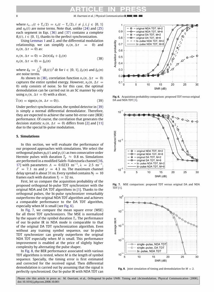
proposed orthogonal bi-pulse TDT synchronizer with theoriginal NDA and DA TDT algorithms in [1]. Thanks to theorthogonal pulses, the bi-pulse synchronizer remarkablyoutperforms the original NDA TDT algorithm and achievesa comparable performance to the DA TDT algorithm,especially whenM is small (see Fig. 6).In Fig. 7, we compare the mean square error (MSE)
for all three TDT synchronizers. The MSE is normalizedby the square of the symbol duration Ts. The performanceof our bi-pulse IR in NDA mode is comparable to thatof the original DA TDT synchronization algorithm. Evenwithout any training symbol sequence, our bi-pulseTDT synchronizer can greatly outperform the originalNDA TDT especially when M is small. This performanceimprovement is enabled at the price of slightly highercomplexity by alternating the pulse shaper.In Fig. 8, the BER performance associated with various
TDT algorithms is tested, where M is the length of symbolsequence. Specially, the timing error is first estimatedand corrected for the received signal. Then differentialdemodulation is carried out by assuming that the signal isperfectly synchronized. Our bi-pulse IR with NDA TDT can
Fig. 6. Acquisition probability comparison: proposed TDT versus originalDA and NDA TDT [1].
Fig. 7. MSE comparison: proposed TDT versus original DA and NDATDT [1].
Fig. 8. Joint simulation of timing and demodulation forM = 2.
Please cite this article in press as: M. Ouertani, et al., Orthogonal bi-pulse UWB: Timing and (de)modulation, Physical Communication (2008),doi:10.1016/j.phycom.2008.10.001

ARTICLE IN PRESSM. Ouertani et al. / Physical Communication ( ) – 9
Fig. 9. Bi-pulse UWB versus noncoherent UWB [2]; timing error is in therange of [0, Ts).
Fig. 10. Comparison of SC, EGC and MRC for bi-pulse UWB; timing erroris in the range of [0, Tf ).
perform almost the same as the original IR with DA TDTand significantly outperform the original IR with NDA TDT.This is in accord with the simulation result that forM = 2,the timing performance of our bi-pulse system is similarto the original TDT in DA mode and much better than theoriginal TDT in NDA mode (see Figs. 6 and 7).In Figs. 9 and 10, we evaluate the BER performance of
our proposed bi-pulse differential demodulator. We alsocompare the bi-pulse UWB with the original noncoherentUWB [2]. In the case of mistiming, the timing error isuniformly distributed in [0, Ts) and [0, Tf ) for Figs. 9 and10, respectively. From Fig. 9, we can see that when there isno mistiming, the bi-pulse noncoherent UWB achieves thesame performance as the original noncoherent UWB. Thisis because with perfect timing, symbol detection of both isessentially differential UWB. By avoiding ISI, our bi-pulsenoncoherent UWB leads to a simple demodulator with MLoptimality even in the presence of unknown mistiming.However, under the same conditions, performance oforiginal noncoherent UWB degrades drastically whenViterbi decoding is not used.
From both Figs. 9 and 10, we see that MRC outperformsEGC and SC in terms of BER. This has been well knownbecauseMRC can alwaysmaximize the SNR of the decisionstatistic. However, which of EGC and SC performs betterdepends on the range of timing error. For the smalltiming error range [0, Tf ), SC performs better (see Fig. 10).However, for the large timing error range [0, Ts), EGCoutperforms SC (see Fig. 9). This is because for the [0, Tf )case, one of the two correlation functions almost containsthe entire energy of the received symbol, but the otherone is almost pure noise. By simply summing up thesetwo terms, EGC actually suffers from an SNR degradation.For the 1τ ∈ [0, Ts) case, the energy contained in bothtwo correlations is generally comparable. Although thestronger one is used for detection, SC still loses a largeportion of the symbol energy. Therefore, EGC outperformsSC when the timing error is in a wider range of [0, Ts), asshown in Fig. 9.
6. Conclusions
In this paper, we proposed a novel bi-pulse IR system,which employs a pair of orthogonal waveforms as pulseshapers in an alternating manner. Based on this system,we developed both a TDT-based timing synchronizer anda noncoherent demodulator. With the orthogonal bi-pulse modulation, our system can completely mitigateISI in the correlation between adjacent half-symbol-longsegments. As a result, our timing synchronizer can achievea better acquisition performance than the original TDTsynchronizer in NDA mode. For the same reason, oursimple demodulator achieves ML optimality without theViterbi decoding required by the original noncoherentUWB.
Acknowledgments
Work at the University of Florida is in part supported byOffice of Naval Research under grant #N00014-07-1-0868.
Appendix. Proof of Lemma 1
Without loss of generality, we assume that the Hermitepulse p0(t) is evenly symmetric and p1(t) is oddlysymmetric, both with respect to the origin [13]. Therefore,p0(t) and p1(t) are two orthogonal pulses.Let c(t) denote the real channel impulse response.2
Then the received pulses corresponding to p0(t) and p1(t)can be expressed as q0(t) = c(t) ∗ p0(t) and q1(t) =c(t) ∗ p1(t). Next let us prove that q0(t) and q1(t) are twoorthogonal pulses, which is equivalent to showing that∫ Tp
2 +Th
−Tp2
q0(t)q1(t)dt = 0 (40)
where Th is the excess delay spread of the channel.
2 Note that c(t) subsumes, but does not have to be, the tap-delay linemodel as in Eq. (3).
Please cite this article in press as: M. Ouertani, et al., Orthogonal bi-pulse UWB: Timing and (de)modulation, Physical Communication (2008),doi:10.1016/j.phycom.2008.10.001

ARTICLE IN PRESS10 M. Ouertani et al. / Physical Communication ( ) –
Using Parseval’s theorem, we can express the left handside of (40) as∫ Tp
2 +Th
−Tp2
q0(t)q1(t)dt =∫ B
2
−B2
Q0(f )Q ∗1 (f )df (41)
where Q0(f ) = F {q0(t)} and Q1(f ) = F {q1(t)} representthe Fourier transform for q0(t) and q1(t), z∗ is the complexconjugate, and B is the bandwidth of the UWB pulse.Due to the basic properties of Fourier transform with
convolution operation, we have Q0(f ) = C(f )P0(f ) andQ1(f ) = C(f )P1(f ), with C(f ) = F {c(t)}, P0(f ) =F {p0(t)} and P1(f ) = F {p1(t)}. Then (41) can be re-expressed as∫ B
2
−B2
Q0(f )Q ∗1 (f )df =∫ B
2
−B2
P0(f )P∗1 (f )|C(f )|2df . (42)
We know that if a function f (t) is a real and evenfunction, then its Fourier transform F(f ) is a real andeven function; if f (t) is a real and odd function, then F(f )is a purely imaginary and odd function. Based on these,P0(f ) turns out to be a real and even function, P1(f ) is apurely imaginary and odd function, and |C(f )|2 is a realand even function. Therefore, P0(f )P∗1 (f )|C(f )|
2 is a purelyimaginary and odd function. As a result, we have∫ Tp
2 +Th
−Tp2
q0(t)q1(t)dt =∫ B
2
−B2
P0(f )P∗1 (f )|C(f )|2df = 0 (43)
which proves that q0(t) and q1(t) are orthogonal. Inother words, the transmitted orthogonal pulses p0(t) andp1(t) remain orthogonal after propagating through a realchannel, regardless of the multipath and possible inter-pulse interference.
References
[1] L. Yang, G.B. Giannakis, Timing Ultra-Wideband signals with dirtytemplates, IEEE Trans. Commun. 53 (11) (2005) 1952–1963.
[2] L. Yang, G.B. Giannakis, A. Swami, Noncoherent Ultra-Wideband(de)modulation, IEEE Trans. Commun. 55 (4) (2007) 810–819.
[3] K. Usuda, H. Zhang, M. Nakagawa, M-ary pulse shape modulationfor PSWF-based UWB systems in multipath fading environment, in:Proc. of Global Telecommunications Conf., GLOBECOM, Dallas, TX,November 29–December 3, 2004, pp. 3498–3504.
[4] I. Dotlic, R. Kohno, Design of the family of orthogonal and spectrallyefficient UWBwaveforms, IEEE J. Sel. Top. Signal Process. 1 (1) (2007)21–30.
[5] J.A. Ney da Silva, M.L.R. de Campos, Spectrally efficient UWB pulseshaping with application in orthogonal PSM, IEEE Trans. Commun.55 (2) (2007) 313–322.
[6] L. Yang, G.B. Giannakis, Ultra-wideband communications: An ideawhose time has come, IEEE Signal Process. Mag. 21 (6) (2004) 26–54.
[7] M.Z. Win, R.A. Scholtz, Impulse radio: How it works, IEEE Commun.Lett. 2 (1998) 36–38.
[8] M. Ouertani, H. Besbes, A. Bouallegue, Modified Hermite functionsfor designing new optimal UWB pulse-shapers, in: European SignalProcessing Conference, EUSIPCO, Antalya, Turkey, September 4–8,2005.
[9] X. Luo, L. Yang, G.B. Giannakis, Designing optimal pulse-shapersfor ultra-wideband radios, IEEE J. Commun. Netw. vol. 5 (4) (2003)344–353.
[10] C.K. Rushforth, Transmitted-reference techniques for random orunknown channels, IEEE Trans. Inform. Theory 10 (1) (1964) 39–42.
[11] M. Ho, V. Somayazulu, J. Foerster, S. Roy, A differential detector foran Ultra-Wideband communications system, in: Proc. of VehicularTechnology Conf., Birmingham, AL, May 4–9, 2002, pp. 1896–1900.
[12] M. Ouertani, H. Xu, L. Yang, H. Besbes, A. Bouallegue, A newmodulation scheme for rapid blind timing acquisition using dirtytemplate approach for UWB systems, in: Proc. of Intl. Conf. onAcoustics, Speech, and Signal Processing, Honolulu, HI, April 15–20,2007, pp. III-265–III-268.
[13] L.B. Michael, M. Ghavami, R. Kohno, Multiple pulse generator forUltra-Wideband communications using Hermite polynomial basedorthogonal pulses, in: Proc. 2002 IEEE Conf. on Ultra WidebandSystems and Tech., Baltimore, MD, May 21–23, 2002, pp. 47–51.
[14] L. Yang, G.B. Giannakis, Optimal pilot waveform assistedmodulationfor Ultra-Wideband communications, IEEE Trans. Wireless Com-mun. 3 (4) (2004) 1236–1249.
[15] J. Proakis, Digital Communications, 4th ed., McGraw-Hill, New York,2001.
[16] R.J.-M. Cramer, R.A. Scholtz, M.Z. Win, Evaluation of an Ultra-Wide-Band propagation channel, IEEE Trans. Antennas Propag. 50 (5)(2002) 561–570.
[17] A.A.M. Saleh, R.A. Valenzuela, A statistical model for indoormultipath propagation, IEEE J. Sel. Areas Commun. 5 (2) (1987)128–137.
[18] T.P. Montoya, G.S. Smith, A study of pulse radiation from severalbroad-band loaded monopoles, IEEE Trans. Antennas Propag. 44 (8)(1996) 1172–1182.
[19] K. Sivanesan, N.C. Beaulieu, Exact BER analysis of bandlimited BPSKwith EGC and SC diversity in cochannel interference and Nakagamifading, IEEE Commun. Lett. 8 (10) (2004) 623–625.
[20] M.K. Simon, M.S. Alouini, Digital Communication Over FadingChannels, Wiley, New York, 2000.
Mourad Ouertani received his Bachelor Degreein Mathematics in 2002, from the Universityof Sciences of Tunis, Tunisia, and Master andPh.D. Degrees in Telecommunications from theNational Engineering School of Tunis (ENIT),Tunisia, in 2003 and 2008, respectively. Hisresearch interests lie in signal processing andcommunication. Currently, he is focusing onsynchronization techniques in UWB systems.
Huilin Xu received the B.Sc. and M. Sc. degreesfrom the University of Science and Technologyof China (USTC), Hefei, China, in 2002 and 2005,respectively, both in Electrical Engineering. Heis currently pursuing the Ph.D degree withthe Department of Electrical and ComputerEngineering, University of Florida, Gainesville,Florida. His research interests are in the areas ofwireless communications and related fields.
Hichem Besbes was born in Monastir, Tunisiain 1966. He received his B.S. (with honors), M.S.degrees and his Ph.D. in Electrical Engineeringfrom the Ecole Nationale d’Ingénieurs de Tunis’(ENIT) in 1991, and 1999, respectively. He hasbeen with the Ecole Supérieure des Communi-cations de Tunis (Sup’Com), as a lecturer during1991–1999 and then as an assistant professor.From July 1999 to October 2000, he held a post-doctoral position at Concordia University, Mon-tréal, Canada. In July 2001, he joined Legerity,
Inc., Austin, Texas, USA, where he was a senior system engineer work-ing on broadband modems. From March 2002 to July 2003, he was amember of Technical Staff at Celite Systems, Inc., Austin, Texas, where hecontributed to definition, design, and development of Celite’s high-speeddata transmission systems overwireline networks, named Broadcast DSL.He is currently an associate professor at Sup’Com. His interests includesignal processing for communication.
Please cite this article in press as: M. Ouertani, et al., Orthogonal bi-pulse UWB: Timing and (de)modulation, Physical Communication (2008),doi:10.1016/j.phycom.2008.10.001

ARTICLE IN PRESSM. Ouertani et al. / Physical Communication ( ) – 11
Liuqing Yang (S’02-M’04-SM’06) received herB.S. degree in Electrical Engineering fromHuazhongUniversity of Science and Technology,Wuhan, China, in 1994, and her M.Sc. and Ph.D.degrees in Electrical and Computer Engineeringfrom University of Minnesota, Minneapolis, in2002 and 2004, respectively. Since August 2004,she has been an assistant professor with theDepartment of Electrical and Computer Engi-neering at University of Florida, Gainesville. Hercurrent research interests include signal pro-
cessing, communications theory and networking. Dr. Yang received theBest Dissertation Award in the Physical Sciences & Engineering from Uni-versity of Minnesota in 2005, and the Office of Naval Research Young In-vestigator Award in 2007. She is the co-recipient of the Best Paper Awardat IEEE international Conference on UWB (ICUWB) in 2006. She servesas an Associate Editor of the IEEE Transactions on Communications, IEEETransactions on Wireless Communications, and IEEE Transactions on In-telligent Transportation Systems. She is also a member of the EditorialBoard of Signal, Image and Video Processing Journal, and PHYCOM: Phys-
ical Communication. Dr. Yang serves as co-chair of the Mobile Communi-cation Networks technical committee of the IEEE ITSS since 2006 and vicechair of the IEEE Gainesville section.
Ammar Bouallègue received the electrical engi-neering, and doctorate degrees from ENSERG deGrenoble, France, in 1971 and1975, respectively,and docteur es-science degree from ENSEEIHT,INP de Toulouse, Toulouse, France, in 1984. In1976, he joined the Ecole Nationale d’Ingénieursde Tunis (ENIT), Tunisia. From 1986 to 1994,he was the head of the Electrical EngineeringDepartment, ENIT, and from 1994 to 1996, hewas the dean of Ecole Supérieure des Postes etdes Télécommunications de Tunis, Tunisia. He
is currently director of the research laboratory Communication Systems(Sys’Com) at ENIT. His research interests include information theory,channel coding, and signal processing for communication.
Please cite this article in press as: M. Ouertani, et al., Orthogonal bi-pulse UWB: Timing and (de)modulation, Physical Communication (2008),doi:10.1016/j.phycom.2008.10.001