art_2009_4_02
DESCRIPTION
kkkTRANSCRIPT

T H E A R C H I V E O F M E C H A N I C A L E N G I N E E R I N G
VOL. LVI 2009 Number 4
Key words: helical spring, helix torsion, spring support, large deflection
KRZYSZTOF MICHALCZYK ∗
ANALYSIS OF HELICAL COMPRESSION SPRING SUPPORTINFLUENCE ON ITS DEFORMATION
This paper presents a new method of calculation of the change of axial twistingangle of compressed helical spring’s end-coils in the case of rotary - free supports.The propriety of derived formulas was experimentally verified. The method is easyin application and gives results much closer to experiment than the presently usedmethod that can be found in literature.
1. Introduction
Helical springs exhibit high sensitivity to supporting conditions [1]. Theshape of end coils influences the stiffness of spring. The way of mountingof the spring’s end coils influences the susceptibility to buckling [2]. Inavailable literature, one can find formulas allowing calculation of the changeof axial twisting angle of statically-compressed helical spring’s end-coils [1,3], but simplifications in these formulas cause that they can not be used forlarge-deflection cases.
2. Analysis of deformation
Figure 1 shows two types of helical spring supports. Fig.1 a) showsrotary-free support of compress helical spring, Fig.1 b) shows fixed supportspreventing ends of the spring from axial twisting. These are two characteristiccases of general support case which acts on spring with axial twisting momentMo as it is shown in Fig. 2. Compressing force F generates two componentsof the moment acting on a spring wire:
∗ AGH University of Science and Technology in Cracow, Poland, Department of Mechani-cal Engineering and Robotics; E-mail: [email protected]

350 KRZYSZTOF MICHALCZYK
Mτ = FD2
cos γ − twisting moment
MN = FD2
sin γ − bending moment
where: γ – the lead angle of spring, D – the nominal diameter of spring.
Fig. 1. Two types of helical spring supports: a) rotary-free support, b) fixed support
Fig. 2. Loads on segment of compressed spring
Substituting
M = F · D2
We obtainMτ = M cos γMN = M sin γ

ANALYSIS OF HELICAL COMPRESSION SPRING SUPPORT INFLUENCE ON ITS DEFORMATION 351
By adding moments of force F with the axial twisting moment Mo, weobtain the equations of moments:– wire bending moment
Mg = M sin γ − Mo cos γ (1)
– wire twisting moment
Ms = M cos γ + Mo sin γ (2)
Elastic energy of bending equals [4]
UG =
L∫
0
M2g
2EJdL (3)
Elastic energy of twisting equals
US =
L∫
0
M2s
2GJodL (4)
Integration is executed over the length of wire. The length of wire equals:
L =πD0
cos γ0zc (5)
where: γo – the initial lead angle of spring;Do – the nominal diameter of not loaded spring;zc – the number of working coils of spring.
The total elastic energy resulting from wire bending and twisting equals
UC = UG + US (6)
After transformations and integration, the formula of total elastic energytakes the form
UC =L
2EJ
((M2 + M2
o
)+ ν
(M2 cos2 γ + 2MMo sin γ cos γ + Mo sin2 γ
))
(7)Accordingly to the Castigliano rule, the derivative of potential energy
with respect to generalised force equals generalised displacement caused bythis force [5]:

352 KRZYSZTOF MICHALCZYK
∂U∂Fn
= wn (8)
Thus, in general case of spring support, the change of twisting angle ofcompressed helical spring’s end-coils equals:
ϑ =∂Uc
∂Mo=
LEJ
(Mo + νM sin γ cos γ + νMo sin2 γ) (9)
In the case of rotary-free support, the twisting moment Mo equals zero.then
ϑ(Mo = 0) =LEJ
νM sin γ cos γ (10)
Formulas (9) and (10) can be found in literature in a similar form [1, 3].They can not be very accurate for high deflections of spring because of theassumption that the lead angle is constant during compression of the spring.Let us transform the formula (10) to form (11), which relates elementaryrotation dϑ to elementary load dF.
For a quite frequent case of mounting element that allows for mutualrotation of spring’s end-coils
dϑ = (LEJ
νR sin γ cos γ)dF (11)
The height of spring H equals L sin γ. For a spring without load, theheight Ho equals L singammao. When loaded, the spring will deflect, with deflection value f , and
its height will equal H = Ho− f . The stiffness of spring equals c =Ff� idem.
Thus, transforming foregoing equations, one can write:
sin γ =H0 − F
c
L(12)
Hence
cos γ =
√1 − (H0 − F
c )2
L2 (13)
From geometric relationships between the spring diameter, the lead angle
of spring γ and the length of spring wire it results that: cos γ =2πR · zc
L,
Thus
R =L
2πzc
√1 − (H0 − F
c )2
L2 (14)
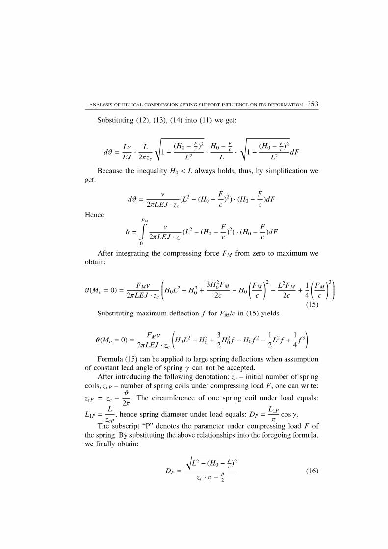
ANALYSIS OF HELICAL COMPRESSION SPRING SUPPORT INFLUENCE ON ITS DEFORMATION 353
Substituting (12), (13), (14) into (11) we get:
dϑ =LνEJ· L2πzc
√1 − (H0 − F
c )2
L2 · H0 − Fc
L·√
1 − (H0 − Fc )2
L2 dF
Because the inequality H0 < L always holds, thus, by simplification weget:
dϑ =ν
2πLEJ · zc(L2 − (H0 − F
c)2) · (H0 − F
c)dF
Hence
ϑ =
PM∫
0
ν
2πLEJ · zc(L2 − (H0 − F
c)2) · (H0 − F
c)dF
After integrating the compressing force FM from zero to maximum weobtain:
ϑ(Mo = 0) =FMν
2πLEJ · zc
H0L2 − H30 +
3H20FM
2c− H0
(FM
c
)2− L2FM
2c+
14
(FM
c
)3(15)
Substituting maximum deflection f for FM /c in (15) yields
ϑ(Mo = 0) =FMν
2πLEJ · zc
(H0L2 − H3
0 +32H2
0 f − H0 f 2 − 12L2 f +
14
f 3)
Formula (15) can be applied to large spring deflections when assumptionof constant lead angle of spring γ can not be accepted.
After introducing the following denotation: zc – initial number of springcoils, zcP – number of spring coils under compressing load F, one can write:
zcP = zc − ϑ
2π. The circumference of one spring coil under load equals:
L1P =L
zcP, hence spring diameter under load equals: DP =
L1P
πcos γ.
The subscript “P” denotes the parameter under compressing load F ofthe spring. By substituting the above relationships into the foregoing formula,we finally obtain:
DP =
√L2 − (H0 − F
c )2
zc · π − ϑ2
(16)

354 KRZYSZTOF MICHALCZYK
Formula (15) can be used to calculate the angle of mutual rotation ofend-coils of loaded spring, whereas formula (16) can be used to calculatethe increase of nominal spring diameter under this load.
The propriety of formulas (10) and (15) has been verified experimentallyon a spring from car suspension system (Fig. 3). The parameters of theexamined spring:
total height l0 – 395 mm; nominal spring diameter Dnom – 119 mm; wirediameter g – 11 mm; number of acting coils nc – 6,27; spiral lead h – 63mm
Fig. 3. Examined spring on experiment station
The angle of mutual rotation of end-coils was measured for spring de-flection equal to f = 200 mm. The results are shown in Table.1. Materialproperties of the examined spring were assumed as typical for steel: E =206000 MPa, ν = 0.3.
Table 1.
Value from: formula (10) formula (15) experiment
ϑ[◦] 7.44 5.8 12.7
As one can see in Tab.1, formula (10) gives the result almost two timeslower than that obtained in experiment. Moreover, formula (15), which takesinto account the change of lead angle gives a result even worse than formula(10),where the change of lead angle is not considered.
A complex investigation was carried out in order to find more preciserelations between the results from formula (10) and experiment. In theseexperiments, we used eighteen springs with different geometrical parameters.
The angle of mutual rotation of end-coils was measured with 0.5[◦]accuracy. Bottom support of spring was made of thrust bearing with lowmoment of friction. Top support of spring was fully constrained.

ANALYSIS OF HELICAL COMPRESSION SPRING SUPPORT INFLUENCE ON ITS DEFORMATION 355
Fig. 4. Experiment station for complex investigations
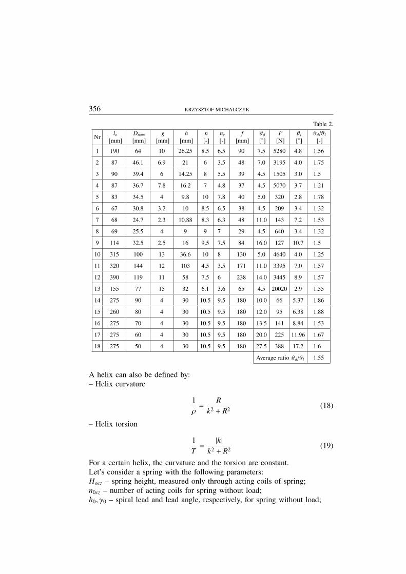
The results are shown in Tab. 2.As one can see in the last column of Tab. 2, the ratio of the experimental
value of axial rotation angle to the value of rotation from formula (10) issignificantly high.
Formula (10) gives results which are not compatible with experimentbecause it has been derived using the Castigliano rule, which can be appliedonly for Clapeyron systems. A spring loaded with axial force and twistingmoment does not fulfil the Clapeyron system’s conditions when large de-flections are considered. Thus, a new formula for mutual rotation of springend-coils must be derived.
The research was conducted in two stages. In the first stage, the assump-tion of constant curvature was made. In the second stage, the change ofcurvature of helix during compression of spring has been considered.
The calculations presented below were done with an assumption thattwisting of the spring’s wire played the major role in its deflection, whereasbending of wire was only a correcting factor.
The parametric equations of a helix have the form [6]:
x = R cosϕ; y = R sin ϕ; z = kϕ (17)
where: R – a half of nominal spring diameter, k – increment of coordinatez referring to increment of angle ϕ from 0 to 2π (Fig. 5). The quantity 2πkmeans the spiral lead.
356 KRZYSZTOF MICHALCZYK
Table 2.
Nrlo
[mm]Dnom
[mm]g
[mm]h
[mm]n[-]
nc
[-]f
[mm]ϑd
[◦]F
[N]ϑl
[◦]ϑd /ϑl
[-]
1 190 64 10 26.25 8.5 6.5 90 7.5 5280 4.8 1.56
2 87 46.1 6.9 21 6 3.5 48 7.0 3195 4.0 1.75
3 90 39.4 6 14.25 8 5.5 39 4.5 1505 3.0 1.5
4 87 36.7 7.8 16.2 7 4.8 37 4.5 5070 3.7 1.21
5 83 34.5 4 9.8 10 7.8 40 5.0 320 2.8 1.78
6 67 30.8 3.2 10 8.5 6.5 38 4.5 209 3.4 1.32
7 68 24.7 2.3 10.88 8.3 6.3 48 11.0 143 7.2 1.53
8 69 25.5 4 9 9 7 29 4.5 640 3.4 1.32
9 114 32.5 2.5 16 9.5 7.5 84 16.0 127 10.7 1.5
10 315 100 13 36.6 10 8 130 5.0 4640 4.0 1.25
11 320 144 12 103 4.5 3.5 171 11.0 3395 7.0 1.57
12 390 119 11 58 7.5 6 238 14.0 3445 8.9 1.57
13 155 77 15 32 6.1 3.6 65 4.5 20020 2.9 1.55
14 275 90 4 30 10.5 9.5 180 10.0 66 5.37 1.86
15 260 80 4 30 10.5 9.5 180 12.0 95 6.38 1.88
16 275 70 4 30 10.5 9.5 180 13.5 141 8.84 1.53
17 275 60 4 30 10.5 9.5 180 20.0 225 11.96 1.67
18 275 50 4 30 10,5 9.5 180 27.5 388 17.2 1.6
Average ratio ϑd /ϑl 1.55
A helix can also be defined by:– Helix curvature
1ρ
=R
k2 + R2 (18)
– Helix torsion
1T
=|k|
k2 + R2 (19)
For a certain helix, the curvature and the torsion are constant.Let’s consider a spring with the following parameters:Hocz – spring height, measured only through acting coils of spring;n0cz – number of acting coils for spring without load;h0, γ0 – spiral lead and lead angle, respectively, for spring without load;

ANALYSIS OF HELICAL COMPRESSION SPRING SUPPORT INFLUENCE ON ITS DEFORMATION 357
Fig. 5. Analysed spring model
H1cz = H0cz − f – acting height of spring under load.The spring is placed in the coordinate system, as it is shown in Fig. 5.
Thus, the coordinates of bottom spring end are: x = R, y = 0, z = 0.The developments of helix of a spring under load and of a one without
load are presented in Fig. 6.
Fig. 6. Developments of helix for two different deflections
The coordinates of top end of the spring without load and that underload equal, respectively,
x0 = R0 cos(2π · n0cz),x1 = R1 cos(2π · n1cz),
y0 = R0 sin(2π · n0cz),y1 = R1 sin(2π · n1cz),
z0 = k0 · (2π · n0cz) = H0cz
z1 = k1 · (2π · n1cz) = H1cz(20)
Because z0 is the spring height and z0 = H0cz, thus the coefficient k0equals:

358 KRZYSZTOF MICHALCZYK
k0 =H0cz
2π · n0cz(21)
On the ground of (18) and (21) one can find the curvature value, whichis initially assumed to be constant independently of spring deflection.
1ρ
=R0(
H0cz2π·n0cz
)2+ R2
0
= idem (22)
Knowing the spring’s wire curvature value 1/ρ, one can calculate thevalue of coefficient k for loaded spring:
k1 =
√ρR1 − R2
1 (23)
On the ground of (21) one can write:
k1 =H1cz
2π · n1cz(24)
On the ground of Fig. 6. one can write:
L2 = H21cz + (2π · n1cz · R1)2
Hence, the number of acting coils of loaded spring equals:
n1cz =
√L2 − H2
1cz
2π · R1(25)
By comparing (23) and (24) we obtain√ρR1 − R2
1 =H1cz
2π · n1cz(26)
After substituting (25) into (26) and transforming the formula, we get
R1 = ρL2 − H2
1cz
L2 (27)
By substituting equation (27) into (25) we obtain, after transformations,the formula for the number of acting coils for loaded spring:
n1cz =
(H2
0cz + (2π · n0cz · R0)2)R0
2π((
H0cz2π·n0cz
)2+ R2
0
) √H2
0cz + (2π · n0cz · R0)2 − H21cz
(28)

ANALYSIS OF HELICAL COMPRESSION SPRING SUPPORT INFLUENCE ON ITS DEFORMATION 359
The angle of mutual rotation of spring’s end-coils during its compressionis equal to the difference between initial and final torsional angle of thespring:
ϑ = ϕ0 − ϕ1 (29)
Therefore
ϑ = 2π ·
n0cz −
(H2
0cz + (2π · n0cz · R0)2)R0
2π((
H0cz2π·n0cz
)2+ R2
0
) √H2
0cz + (2π · n0cz · R0)2 − H21cz
(30)
The foregoing calculations were conducted with an assumption of con-stant wire curvature. Now, the change of wire curvature during spring com-pression will be considered. The change of torsion is the result of twistingmoment, whilst the change of curvature is the result of bending moment:
1T
= f (Mτ)1ρ
= f (MN )
The relation between curvature, elastic modulus, moment of inertia andbending moment is as follows [7]:
1ρz
=MN
EJ(31)
The subscript ”z” in formula (31) means that it is a change of curvature,not its entire value. The entire value of curvature is the sum (in the case oftension spring – difference) of initial wire curvature and its change followingon spring compression.
1ρ
=1ρ0
+1ρz
(32)
Transformation of (31) yields
1ρz
=FD2EJ
sin γ1 (33)
Transforming standard formula for helical spring deflection [8] we get:
F =(H0cz − H1cz)Gd4
8 · D3 · ncz(34)
On the ground of Fig. 6 one can write:

360 KRZYSZTOF MICHALCZYK
sin γ1 =H1cz
L(35)
Substituting transformations of formulas (33, 34, 35) into (32) we obtain
1ρ1
=1ρ0
+(H0cz − H1cz)GπR2
0 · n0cz · E· H1cz
L(36)
Using the dependence E/G = 2(1 + ν) [7] and equation (22), on theground of (27) one can write
R1cz =
L2
L2 − H21cz
·
R0(H0cz
2π·n0cz
)2+ R2
0
+(H0cz − H1cz)
2πR20 · n0cz · (1 + ν)
· H1cz
L
−1
(37)
Thus, the number of working coils of loaded spring, considering thechange of wire curvature, equals
n1cz =L2
2π√
L2 − H21cz
R0(
H0cz2π·n0cz
)2+ R2
0
+(H0cz − H1cz)
2πR20 · n0cz · (1 + ν)
· H1cz
L
(38)
Finally, the dependence for the angle of mutual rotation of the end-coilsis given in the form:
ϑ = 2πn0cz− L2
√L2 − H2
1cz
R0(
H0cz2π·n0cz
)2+ R2
0
+(H0cz − H1cz)
2πR20 · n0cz · (1 + ν)
· H1cz
L
(39)
The results of formula (39) were compared with experimental resultsshown in Tab. 2. The results of the comparison are shown in Tab. 3.
As one can notice, the results are quite coincident, so that formula (39)gives results much more accurate than formula (10) that has been applied todate.

ANALYSIS OF HELICAL COMPRESSION SPRING SUPPORT INFLUENCE ON ITS DEFORMATION 361
Table 3.
No. Of springfrom Tab. 2
The value of twisting angle θfrom the experiment in [◦]
The value of twistingangle θ from (39) in [◦]
The ratio betweenϑ from the experiment
and from (39)
1 7.5 7.8 0.961
2 7.0 7.1 0.986
3 4.5 4.9 0.918
4 4.5 4.6 0.978
5 5.0 4.4 1.136
6 4.5 5.2 0.865
7 11.0 11.9 0.924
8 4.5 4.9 0.918
9 16.0 17.8 0.9
10 5.0 5.9 0.847
11 11.0 9.6 1.146
12 14.0 15.1 0.927
13 4.5 4.6 0.978
14 10.0 9.3 1.075
15 12.0 11.5 1.043
16 13.5 15.3 0.882
17 20.0 20.7 0.966
18 27.5 29.5 0.932
Average ratio ϑd /ϑ(39) 0.965
3. Conclusions
In this paper, we have shown that formula (10), still applied in literature,can not be used to calculate the angle of mutual rotation of spring’s end-coilsin the case of strongly deflected, rotationally-free supported spring. Formula(10) was derived on the basis of assumption that the spring is the Clapeyronsystem. This assumption, however, is not true for the analysed phenomena,because the dependence between the angle of mutual rotation of end-coilsand the change of spring’s height during compression is not linear. Theattempt of reducing simplifying assumptions gave results even more distantfrom experiment results than those calculated with formula (10).

362 KRZYSZTOF MICHALCZYK
Formula (39), derived in this paper on the ground of a new approachto the problem, gave much more accurate results, which was verified ex-perimentally. The change of lead angle was taken into consideration. Theanalysis of formula (10) shows that, when we use it, a negative value oftwisting angle can never be obtained. For very high values of lead angle,mutual rotation of spring’s end-coils will have a negative value, and such aresult can be obtained on the ground of formula (39).
Manuscript received by Editorial Board, May 19, 2009;final version, August 26, 2009.
REFERENCES
[1] Branowski B.: Sprężyny metalowe. PWN, Warszawa, 1997.[2] Chassie G. G., Becker L. E., Cleghorn W. L.: On the buckling of helical springs under
combined compression and torsion. Int. J. Mech. Sci.1997, Vol. 39, No. 6, pp. 697-704.[3] Kożeśnik J.: Dynamika Maszyn. WNT, Warszawa 1963.[4] Walczak J.: Wytrzymałość materiałów oraz podstawy teorii sprężystości i plastyczności, PWN,
Warszawa, 1978.[5] Lindkvist, L.: Three-dimensional load-deformation relation ships of arbitrarily loaded coiled
springs. Machine and Vehicle Design, Chalmers University of Technology, Sweden. 1995.[6] Leja F.: Geometria analityczna, PWN, Warszawa 1976.[7] Kurowski R., Niezgodziński M. E.: Wytrzymałość Materiałów, PWN, Warszawa 1999.[8] Rivin E. I: Passive vibration isolation. ASME PRESS, New York 2003.
Analiza wpływu podparcia sprężyny śrubowej naciskowej na jej odkształcenia
S t r e s z c z e n i e
W pracy zaprezentowano nową metodę obliczania kąta skręcenia czół sprężyny śrubowejnaciskowej pod obciążeniem dla przypadku obrotowo podatnego podparcia jej końców. Poprawnośćwyprowadzonych zależności zweryfikowano doświadczalnie. Metoda ta jest prosta w zastosowaniui daje wyniki znacznie bliższe wynikom eksperymentu niż metoda znana z literatury i dotychczasstosowana.