arrimax service manual · remove 10 screws (10 mm ratchet) 6 (black) screws three on each side and...
TRANSCRIPT
S E R V I C E M A N U A L
Date: April 23, 2019
Supported Models
L1.37950.B
ARRIMAX 18/12

ARRIMAX – Service Manual Page 2 of 20
Version History
Version Author Change Note
03/2019 S. Papke Original version
Table of Contents
Version History .................................................................................................................. 2
Table of Contents ............................................................................................................... 2 Important Information........................................................................................................ 3 Safety Instructions ............................................................................................................. 3 General Safety Requirements for Operating Lamphead Systems ................................ 3
Required Tools ................................................................................................................... 4 Disassembling Order ......................................................................................................... 5 Safety Switch Activator (SSA) .......................................................................................... 6
Lens Door ........................................................................................................................... 7 Reflector: Replacement and Maintenance ...................................................................... 8
Back Housing ..................................................................................................................... 9 Lamp Carriage Removal .................................................................................................. 10
Lamp Carriage Adjustment ............................................................................................. 13 Lamp Cables ..................................................................................................................... 15 Fan Cooling System & Maintenance .............................................................................. 16
Remove Bottom Plate and Skid ...................................................................................... 17 Maintenance and Care ..................................................................................................... 18
Visual Inspection ............................................................................................................. 18 Cleaning ............................................................................................................................ 18
Testing of Mechanical Components .............................................................................. 18 Contact .............................................................................................................................. 20
Further Information .......................................................................................................... 20
ARRIMAX – Service Manual Page 3 of 20
Important Information
This instruction supports only the models listed on page 1. If your model is not listed, please visit
www.arri.com/service-lighting for more information. Also, these instructions are for qualified ARRI service
personnel only. If you are not familiar with the handling of components that can be destroyed by high voltage
or electrostatic discharge, please do not use these instructions and contact the ARRI Lighting Service Team.
Safety Instructions
The following instructions contain helpful advice on how to operate your ARRI lamp head safely. Lamp
heads, lamp head systems and accessories may only be operated and used by qualified persons and only
for professional lighting purposes. Relevant operating instructions must be followed for the equipment you
are using. Please also refer to the Ordinance on Industrial Safety and Health as well as the relevant
guidelines and regulations of your national Industrial Injuries Corporation (e.g. BGI 810-1, -3 and -4, BGV A1
for Germany; OSHA or ESTA for USA; etc.). Please refer also to our leaflet "Operating your ARRI Lamp
heads safely" L5.70431.E
General Safety Requirements for Operating Lamphead Systems
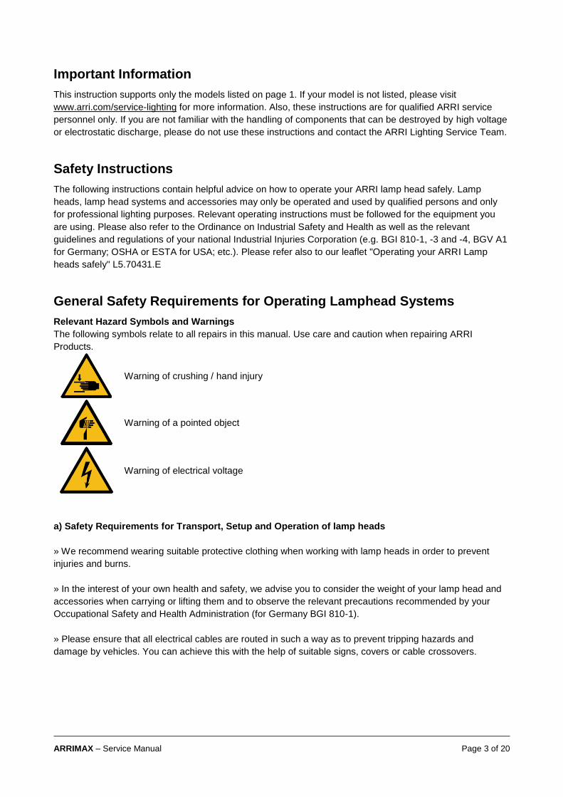
Relevant Hazard Symbols and Warnings
The following symbols relate to all repairs in this manual. Use care and caution when repairing ARRI
Products.
Warning of crushing / hand injury
Warning of a pointed object
Warning of electrical voltage
a) Safety Requirements for Transport, Setup and Operation of lamp heads
» We recommend wearing suitable protective clothing when working with lamp heads in order to prevent
injuries and burns.
» In the interest of your own health and safety, we advise you to consider the weight of your lamp head and
accessories when carrying or lifting them and to observe the relevant precautions recommended by your
Occupational Safety and Health Administration (for Germany BGI 810-1).
» Please ensure that all electrical cables are routed in such a way as to prevent tripping hazards and
damage by vehicles. You can achieve this with the help of suitable signs, covers or cable crossovers.

ARRIMAX – Service Manual Page 4 of 20
b) Safety Requirements Concerning Electrical Danger
» Please check the lamp head system and its electrical protection device before each use.
» The faultless function of the power supply and protection system must be ensured before connecting the
lamp head (e.g. grounding, circuit breaker).
It might be necessary to install additional protection measures; for example:
» the application of residual current operated protective devices (RCDs)
» the application of safety extra low voltage, protective separation or protective insulation
» equipotential bonding
Required Tools
1 Torx Screwdriver TX 20
2 Screwdriver Philips PH2
3 Ratchet: 13mm and 10mm
4 Allen Key size 1.5 mm
5 L4.85204.E Adjustment Pins G38 base (Set)
ARRIMAX – Service Manual Page 5 of 20
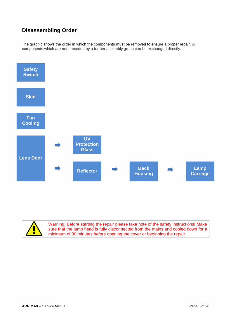
Disassembling Order
The graphic shows the order in which the components must be removed to ensure a proper repair. All components which are not preceded by a further assembly group can be exchanged directly.
Warning: Before starting the repair please take note of the safety instructions! Make sure that the lamp head is fully disconnected from the mains and cooled down for a minimum of 30 minutes before opening the cover or beginning the repair.
Safety Switch
Skid
Fan Cooling
Lens Door
UV Protection
Glass
Reflector
Back Housing
Lamp Carriage

ARRIMAX – Service Manual Page 6 of 20
Safety Switch Activator (SSA)
Set the Focus to Spot. The reflector is now in
position to open the lens door.
Loosen 1 screw (1.5 mm Allen key) directly
below the SSA. Do not remove.
Now you can move the SSA forward or
backwards to find the right adjustment.
To adjust:
• Allow a small amount of play (C) when
the silver pin (A) contacts the activator
(B).
• When closing the door listen for a
‘click’ sound.
• It should ‘click’ twice before the door
latch closes completely
If this is not adjusted properly than the safety
loop can be opened, and the lamp will not
strike.
Note: You can also measure the safety loop
refer to the wiring diagram.
Important: If the door latch is not adjusted
properly this affects the SSA function.
A B
C
ARRIMAX – Service Manual Page 7 of 20
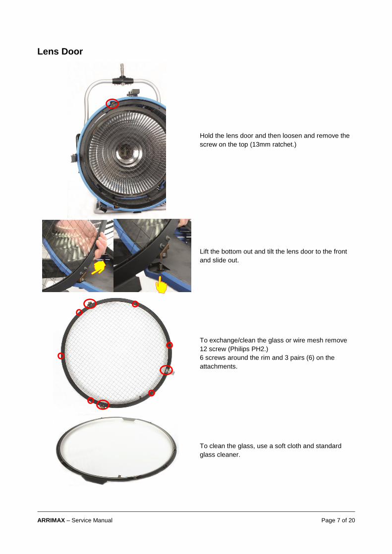
Lens Door
Hold the lens door and then loosen and remove the
screw on the top (13mm ratchet.)
Lift the bottom out and tilt the lens door to the front
and slide out.
To exchange/clean the glass or wire mesh remove
12 screw (Philips PH2.)
6 screws around the rim and 3 pairs (6) on the
attachments.
To clean the glass, use a soft cloth and standard
glass cleaner.
ARRIMAX – Service Manual Page 8 of 20
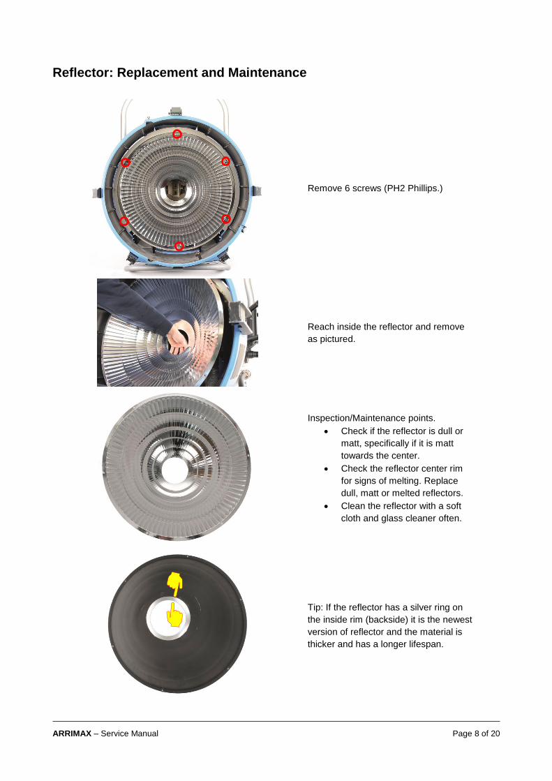
Reflector: Replacement and Maintenance
Remove 6 screws (PH2 Phillips.)
Reach inside the reflector and remove
as pictured.
Inspection/Maintenance points.
• Check if the reflector is dull or
matt, specifically if it is matt
towards the center.
• Check the reflector center rim
for signs of melting. Replace
dull, matt or melted reflectors.
• Clean the reflector with a soft
cloth and glass cleaner often.
Tip: If the reflector has a silver ring on
the inside rim (backside) it is the newest
version of reflector and the material is
thicker and has a longer lifespan.

ARRIMAX – Service Manual Page 9 of 20
Back Housing
Remove 10 screws (10 mm ratchet) 6
(black) screws three on each side and 4
shorter silver screws which are located
on the top.
Turn the lamphead around to access the
screws in the back. Remove the 4 black
screws (Philips PH2) on the bottom half.
Holding the stirrup handles, lift the
housing up (min of 5 cm) and slide the
entire back housing off. Otherwise it is
possible to damage the insulation of the
HT Cables.

ARRIMAX – Service Manual Page 10 of 20
Lamp Carriage Removal
Remove 4 screws (Torx 20) as shown.
Move the focus to flood and then you can
access two additional screws (Torx 20.)

ARRIMAX – Service Manual Page 11 of 20
Remove 2 screws (13 mm rachet) as shown.
Tip: Screw them back to avoid losing them.

ARRIMAX – Service Manual Page 12 of 20
Remove lamp carriage assembly.

ARRIMAX – Service Manual Page 13 of 20
Lamp Carriage Adjustment
Position the lamp carriable assembly on the
frame as shown.
Install the 4 screws (Torx 20) without
completely tightening them.
Reinstall the HT cables (13 mm wrench.)
Install 2 screws (Torx 20) on the side without
completely tightening them. The focus must be
set to flood.
Use the gauge Min or Max. The gauge set is
part number L4.85204.E
Insert the gauge in the lamp socket as shown
and lock the lampholder.
Focus to flood. The screws on both sides on
the lamp carriage are now accessible.

ARRIMAX – Service Manual Page 14 of 20
Attach the black plate on the front and slide it in
to the reflector carriage as shown.
Tighten 6 screws (Torx 20.)
Open the lamp lock and remove the gauge and
the black adjustment plate.
.
When sliding the back housing back on, the two
fins of the baffles must be inside the flood/spot
baffle as shown.

ARRIMAX – Service Manual Page 15 of 20
Lamp Cables
After removing the lamp carriage remove the
lamp cables by unscrewing the two PTFE
(white bushing as seen in picture.)
The longer cable is installed in the front and the
short cable facing the back of the lamphead.

ARRIMAX – Service Manual Page 16 of 20
Fan Cooling System & Maintenance
To access the cooling system for the
reflector/lampholder (2 front fans) remove the
lens door and reflector.
Place the lampead face down with the skid
facing you.
See the two service doors to access the fans.
Remove 4 screws (Phillips PH2) from the
doors. Carefully pull away.
Important: Maintain the fans by cleaning them
regularily. Keep the fans free of debree/bugs.
Failure can do so can cause damage to the
reflector.
Important: Watch that the flat cable connectors
are properly positioned and connected.
The fan must be installed in the right direction.
The air stream must move towards the inside of
the lamphead.
ARRIMAX – Service Manual Page 17 of 20
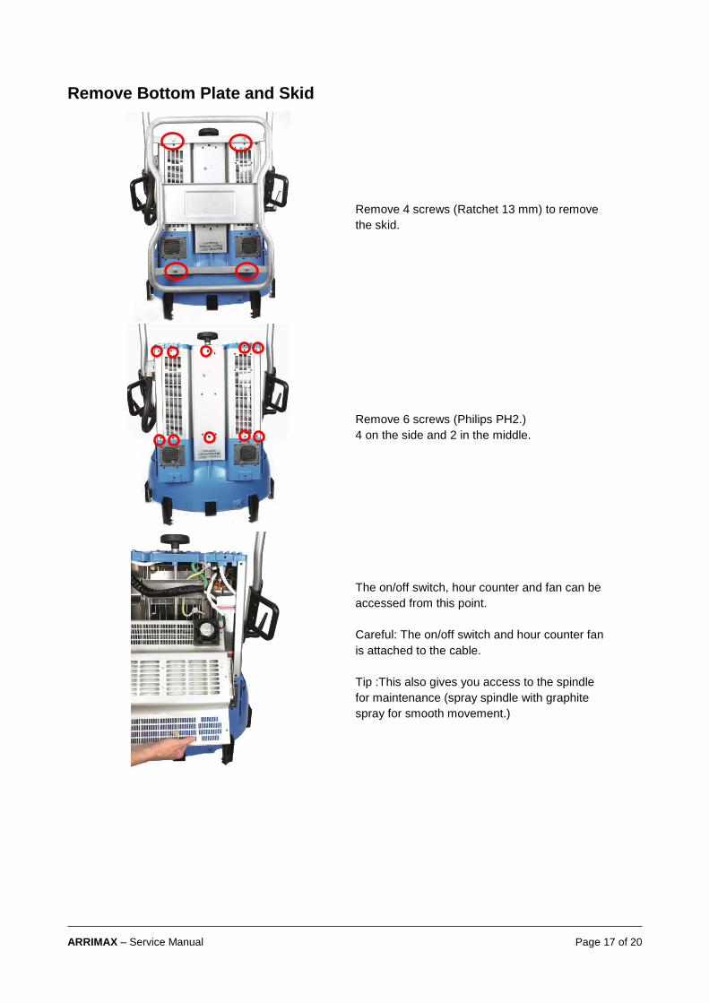
Remove Bottom Plate and Skid
Remove 4 screws (Ratchet 13 mm) to remove
the skid.
Remove 6 screws (Philips PH2.)
4 on the side and 2 in the middle.
The on/off switch, hour counter and fan can be
accessed from this point.
Careful: The on/off switch and hour counter fan
is attached to the cable.
Tip :This also gives you access to the spindle
for maintenance (spray spindle with graphite
spray for smooth movement.)

ARRIMAX – Service Manual Page 18 of 20
Maintenance and Care
Please do not forget that the safe operation of lamp heads also includes their maintenance and care. A visual inspection should be conducted before every use, and an inspection of electrical safety should be conducted at least once every 12 months. The results of these repeated inspections should be documented and filed. You will find additional information for the setup and operation of your lamp head, as well as information on the special features of the individual lamp head models, in the relevant operating instructions. Our recommendations for maintenance of this lamphead can be found on the following pages.
Visual Inspection
We recommend a regular visual inspection. This helps to detect potential damages in an early state. This is the only way to prevent and avoid consequential damage to other components. If your lamp head shows any visual damage, please contact your local ARRI service partner.
Cleaning The lamp head should be cleaned regularly. This is not just for your own safety; it also increases the lifespan of the device significantly. The following components should be cleaned regularly:
1. Cleaning the UV protection glass: Use conventional glass cleaner and a soft cloth for cleaning the protection glass.
2. Cleaning the reflector
Follow the steps for “Lens holder” + “Reflector” Use conventional glass cleaner and a soft cloth for cleaning the reflector.
3. Cleaning the inner housing
Follow the steps “Lens holder” and “Housing” in this manual. Clean the inner housing carefully with a vacuum cleaner and get rid of dust and
insects.
Testing of Mechanical Components
The following mechanical components should be checked regularly for functionality:
1. Safety switch
When setting or checking the safety switch you must ensure that you hear the clicking noise 2 times before the lens door is closed completely. If you are not sure if your lamp head is set correctly please contact immediately your local ARRI service partner for more information on how to proceed.
2. Lamp socket
Burn marks or discoloration may be an indication for contact problems. We strongly recommend a replacement to avoid damage on the lamp head. Please contact your local ARRI service partner for more information about how to adjust the lamp socket correctly.

ARRIMAX – Service Manual Page 19 of 20

ARRIMAX – Service Manual Page 20 of 20
Contact
In case you have questions or recommendations, please contact the Global Application & Services department within ARRI via email: [email protected]
Further Information
The manufacturer disclaims liability for any damage to persons or properties which are caused by an inappropriate operation of the fixture. Those lie in the responsibility of the operator. Visit our homepage www.arri.com/service-lighting for downloads and software tools.