ar/pd 10-04 e 30 jan 2013 superseding ar/pd 10-04 d ... · pdf fileaatcc method 135 - ... po...
TRANSCRIPT

AR/PD 10-04 Rev E Page 1 of 77
INCH POUND
AR/PD 10-04 E
30 JAN 2013
Superseding
AR/PD 10-04 D
1 SEP 2012
PURCHASE DESCRIPTION
SOLDIER PLATE CARRIER SYSTEM (SPCS)
This document is approved for use by all Departments and Agencies of the Department of
Defense (DOD). Recommended improvements, simplifications, or reductions in paperwork are
encouraged and should be directed to the preparing activity.
1. SCOPE
1.1 Description. This purchase description provides for a multiple threat body armor system
consisting of a base vest, cummerbunds and side plate pockets for tailoring protection levels to
defeat multiple ballistic hazards across the battlefield continuum and manage armor weight. The
SPCS is a critical safety item. This specification delineates system, subsystem, component, and
subcomponent level performance requirements to accomplish the end item body armor
performance (see paragraph 6.1). SPCS is functionally integrated with Modular Lightweight
Load-carrying Equipment (MOLLE).
1.2 Classification. SPCS consists of three (3) main components; base vest (front and back) with
ballistic panels, side pockets (2) with ballistic panels, and cummerbund (2) with ballistic panels.
The SPCS shall be used in conjunction with Enhanced Small Arms Protective Inserts (ESAPI), X
Small Arms Protective Inserts (XSAPI), Enhanced Side Ballistic Insert (ESBI), and X Side
Ballistic Insert (XSBI).
Beneficial comments (recommendations, additions, deletions) and any pertinent data which
may be used in improving this document should be addressed to: Product Manager – Soldier
Protective Equipment, Program Executive Office – Soldier, US Army, 10170 Beach Road,
Building 328T, Fort Belvoir, Virginia

AR/PD 10-04 Rev E Page 2 of 77
A) The SPCS subsystem; consisting of the base vest assembly, side panels, and
cummerbund.
COMPONENT SIZES
Base Vest Assembly 6 sizes: X-Small, Small, Medium, Large, X-Large,
2X-Large
Side Panels One size
Cummerbund 3 sizes: X-Small-Small, Medium-Large, X-Large-
2X-Large
B) The SAPI subsystem; consisting of a set of ESAPI or XSAPI in the same size as the
SPCS.
COMPONENT SIZES
Small Arms Protective Insert 5 sizes: X-Small, Small, Medium, Large, X-Large
(ESAPI, XSAPI)
C) The Enhanced Side Ballistic Insert or X-Side Ballistic Insert subsystem; consisting of a
set of ESBI/XSBI in one standard size.
COMPONENT SIZES
Enhanced Side Ballistic Insert One size
X-Side Ballistic Insert
(ESBI/XSBI)
2. APPLICABLE DOCUMENTS
2.1 General. The documents listed in this section are specified in sections 3 and 4 of this
performance requirement. This section does not include documents cited in other sections of this
specification or recommended for additional information or as examples. While every effort has
been made to ensure the completeness of this list, document users are cautioned that they must
meet all specified requirements documents cited in sections 3 and 4 of this specification, whether
or not they are listed.
2.2 Government documents.
2.2.1 Specifications, standards, and handbooks. The following specifications, standards, and
handbooks form a part of this document to the extent specified herein. Unless otherwise
specified, the issues of these documents are those listed in the issue of the Department of
Defense Index of Specifications and Standards (DoDISS) and supplement thereto, cited in the
Solicitation (see paragraph 6.2).

AR/PD 10-04 Rev E Page 3 of 77
SPECIFICATIONS
DEPARTMENT OF DEFENSE
TOP 10-2-210 V4 - Ballistic Testing of Hard Body Armor Using Clay Backing
MIL-DTL-32075 - Label: For Clothing, Equipage, and Tentage (General Use)
MIL-PRF-5038 - Tape, Textile and Webbing, Textile, Reinforcing Nylon
MIL-PRF-63460 - Lubricant, Cleaner and Preservative for Weapons and Weapons
Systems (Metric)
CO/PD 04-19 - Enhanced, Small Arms Protective Inserts (ESAPI)
FQ/PD 07-03 - X Small Arms Protective Inserts (XSAPI)
CO/PD 06-20 - Enhanced Side Ballistic Insert (ESBI)
AR/PD 10-03 - X-Side Ballistic Insert (XSBI)
GL/PD 10-07 - Cloth, Duck, Textured Nylon
A-A-59826 - Thread, Nylon
A-A-55301 - Webbing, Textile Textured or Multi-Filament
A-A-55126 - Fastener Tape, Hook and Pile, Synthetic
MIL-STD-662 - V50 Ballistic Test for Armor
MIL-STD-3027 - Performance Requirements and Testing of Body Armor (see 6.5)
MIL-DTL-46593 - Projectile, Calibers .22, .30, .50, and 20 mm Fragment-
Simulating
MIL-W-17337 - Webbing, Textile, Woven Nylon
MIL-STD-810 - Environmental Engineering Considerations and Laboratory Tests
MIL-STD-130 - Identification Marking of U.S. Military Property
MIL-STD-1916 - DoD Preferred Method for Acceptance of Product
MIL-DTL-23053 - Detail Specification for Heat Shrinkable Tubing
(Unless otherwise indicated, copies of the above specifications, standards, and handbooks are
available from the Standardization Document Order Desk, 700 Robbins Avenue, Building 4D,
Philadelphia, PA 19111-5094 or www.dsp.dla.mil using Assist Quick Search).
2.2.2 Other Government documents, drawings, and publications. The following other
Government documents, drawings, and publications form a part of this document to the extent
specified herein. Unless otherwise specified, the issues are those cited in the solicitation.
ITOP 4-2-805 - Projectile Velocity and Time of Flight Measurements
TOP 10-2-210A - Ballistic Testing of Hard Body Armor using Clay Backing
DRAWINGS
For any camouflage patterns noted in the solicitation and/or contract, please contact the
contracting activity for the necessary drawings and/or patterns.

AR/PD 10-04 Rev E Page 4 of 77
ENGINEERING DRAWINGS
Project Manager – Soldier Protection and Individual Equipment, Program Executive Office –
Soldier, Fort Belvoir, VA
MANUALS
TM 10-8400-203-23 General Repair Procedures for Individual Equipment; Chapter 25,
Maintenance of Interceptor Body Armor System
GSA Federal Standardization Manual 2000
(Copies of drawings, publications, and other Government documents required by contractors in
connection with specific acquisition functions should be obtained from the contracting activity or
as directed by the contracting activity.)
2.3 Non-government publications. The following documents forms a part of this document to
the extent specified herein. Unless otherwise specified, the issues of the documents which are
Department of Defense adopted are those listed in the issue of the DoDISS cited in the
solicitation. Unless otherwise specified, the issues of documents not listed in the DoDISS are the
issues of the documents cited in the solicitation (see paragraph 6.2).
AMERICAN ASSOCIATION OF TEXTILE CHEMISTS AND COLORISTS (AATCC)
AATCC METHOD 8 - Colorfastness to Crocking; AATCC Crockmeter Method
AATCC METHOD 15 - Colorfastness to Perspiration
AATCC METHOD 16 - Colorfastness to Light
AATCC METHOD 22 - Water Repellency; Spray Test
AATCC METHOD 61 - Colorfastness to Laundering: Accelerated
AATCC METHOD 70 - Water Repellency: Tumble Jar Dynamic Absorption Test
AATCC METHOD 96 - Dimensional Changes in Commercial Laundering of Woven and
Knitted Fabrics except Wool
AATCC METHOD 118 - Oil Repellency: Hydrocarbon Resistance Test
AATCC METHOD 127 - Water Resistance: Hydrostatic Pressure Test
AATCC METHOD 135 - Dimensional Changes of Fabrics after Home Laundering Related to
ISO 3759
AATCC Procedure 1 - Gray Scale for Color Change
AATCC Procedure 2 - Gray Scale for Staining
AATCC Procedure 8 - Step Chromatic Transference Scale
AATCC Procedure 9 - Visual Assessment of Color Difference of Textiles
(Applications for copies should be addressed to the American Association of Textile Chemists
and Colorists, PO Box 12215, Research Triangle Park, NC 27709-2215 or www.aatcc.org).
AMERICAN SOCIETY FOR TESTING AND MATERIALS (ASTM)
ASTM E29 - Standard Practice for Using Significant Digits in Test Data to
Determine Conformance with Specifications
ASTM D-204 - Sewing Threads

AR/PD 10-04 Rev E Page 5 of 77
ASTM D-1388 - Stiffness of Fabrics
ASTM D-1683 - Failure in Sewn Seams of Woven Fabrics
ASTM D-1777 - Standard Method for Testing Thickness of Textile Materials
ASTM D-3575 - Materials, Flexible Cellular, Made From Olefin Polymers
ASTM D-3776 - Mass per Unit Area (Weight) of Woven Fabric
ASTM D-3884 - Abrasion Resistance of Textile Fabrics, (Rotary Platform, Double
Head Method)
ASTM D-3886 - Abrasion Resistance of Textile Fabrics, (Inflated Diaphragm)
ASTM D-4485 - Standard Specification for Performance of Engine Oils
ASTM D-5034 - Breaking Force and Elongation of Textile Fabrics (Grab Test)
ASTM D-6193 - Standard Practice for Stitches & Seam
ASTM D-6413 - Standard Test Method for Flame Resistance of Textiles (Vertical
Test)
(Applications for copies should be addressed to ASTM International, 100 Barr Harbor Drive, PO
Box C700, West Conshohocken, PA 19428-2959 or www.astm.org)
AMERICAN NATIONAL STANDARDS INSTITUTE (ANSI)
ANSI/ASQ Z1.4-2008 - Sampling Procedures and Tables for Inspection by Attributes
INTERNATIONAL ORGANIZATION FOR STANDARDIZATION (ISO)
ISO 16022 - Information Technology Automatic Identification and Data Capture Techniques
Data Matrix Bar Code Symbology Specification
2.4 Order of precedence. In the event of a conflict between the text of this document and the
references cited herein, the text of this document takes precedence. Nothing in this document,
however, supersedes applicable laws and regulations unless a specific exemption has been
obtained.
3. REQUIREMENTS
3.1 Product Verification Testing (PVT), First Article Testing (FAT) and Lot Acceptance
Testing (LAT). When specified, complete SPCS samples, representing full production quality,
shall be subjected to PVT and FAT in accordance with 4.2 or LAT in accordance with 4.3. Prior
to PVT submittal, the contractor shall provide data that shows all the components and materials
used in the SPCS meet all stated requirements of the Technical Data Package (TDP) outlined in
Appendix D. Additional TDP requirements may be required per the contract.
3.2 Materials and components. The materials and components shall conform to applicable
specifications, standards, and patterns required herein.
3.2.1 Cloth Outer and Inner Shell (Body Side). The outer shell fabric shall be textured nylon
duck conforming to GL-PD 10-07 Type III Class 4, and Style as specified in the contract except
that flame resistance shall be in accordance with paragraph 3.2.1.1. The inner shell fabric (side
worn against the body) shall be textured nylon duck conforming to GL-PD 10-07 Type III Class
3, and Style as specified in Appendix A, Table II. If additional Styles are required it will be

AR/PD 10-04 Rev E Page 6 of 77
dictated within the contract. Type III Class 4 shall also be considered acceptable for the inner
shell.
3.2.1.1 Flame Resistant Requirements: The finished cloth(s), outer shell as specified in para.
3.3.1.1, shall exhibit flame resistance. All materials tested shall be tested in both the warp and
fill directions. The average melt/drip that occurs after removal of source flame shall be less than
1 droplet. The average afterflame in each direction (warp and fill) shall be no longer than 3.0
seconds, the average afterglow in each direction shall be no longer than 2.0 seconds, and the
average char length in each direction shall be no longer than 4 ½ inches for samples prior to
laundering (0 washes) and after laundering (5 washes). The average will be taken by combining
all the subtests for their respective tests. Laundering shall be conducted according to AATCC
Method 135, and the vertical flame testing shall be conducted according to ASTM D 6413.
3.2.1.2 Pattern Execution: The pattern on the printed finished cloth shall be reproducible to the
standard sample in respect to design, colors and registration of the respective areas. Various
areas of the pattern shall be properly registered in relation to each other and shall present definite
sharp demarcations with a minimum of feathering or spew. Each pattern area shall show solid
coverage; skitteriness exceeding that shown on the standard sample in any of the printed areas
will not be acceptable. Solid shades shall demonstrate level dyeing uniformity. When the
standard sample is not referenced for pattern execution, a pattern drawing shall be provided by
the contracting or procuring activity upon request. Camouflage color will be specified in the
contract. See Appendix A, Table II for individual piece colors.
3.2.2 Cloth Ballistic Panel Cover. Ballistic panel cover should be water tight over cover that is
either 70 or 200 Denier Nylon ripstop that is heat sealed around the ballistic filler. The ballistic
panel cover shall be water resistant and provide a shelf life/service life of 5 years. Camouflage
color will be specified in the contract. See Appendix A, Table II for individual piece colors.
3.2.3 Webbing and Tapes. Webbings and tapes shall be heat cut smooth with no burrs or
residual melt. When required, angles on webbings shall be 45° ±10° unless otherwise specified
on the drawings or templates. Webbings and tapes shall conform to the following requirements.
a) 3/4 inch Webbing; A-A-55301, Type IV, width 0.75 inch ±1/16. Producer colored or
piece/yarn dyed, textured, filament nylon are acceptable: warp ends: 69 min; binder ends: 8
min; picks/inch: 66 min. Weight: 0.48 oz/yd min; break strength: 800 lbs min; thickness:
0.039 inch min.
b) 1 inch Webbing; A-A-55301, Type III, width 1.0 inch ±1/16. Alternate construction is not
acceptable. Producer colored or piece/yarn dyed, textured, filament nylon are acceptable:
warp ends: 101 min; binder ends: 15 min; picks/inch: 72 min. Weight: 0.50 oz/yd min; break
strength: 1000 lbs min; thickness: 0.039 inch min.
c) 1 1/2 inch Webbing; A-A-55301, Type VI, width 1.5 inch ±1/16. Producer colored or
piece/yarn dyed, textured, filament nylon are acceptable: warp ends: 144 min; binder ends:
16 min; picks/inch: 80 min. Weight: 0.90 oz/yd min; break strength: 1350 lbs min; thickness:
0.039 inch min.

AR/PD 10-04 Rev E Page 7 of 77
d) 2 inch Webbing; MIL-W-17337 Class 2, width 2.0 inch ±1/8. Producer colored, textured,
filament nylon: warp ends: 160 min; binder ends: 38 min; picks/inch: 72 min. Non-textured,
filament nylon: warp ends: 193 min; binder ends: 46 min; picks/inch: 72 min. Weight: 1.15
oz/yd min; break strength: 1950 lbs min; thickness: 0.039 inch min.
e) 1 inch Tape; MIL-PRF-5038, Type III, Class 2, width 1.0 inch ±1/16. Producer colored,
textured, filament nylon (500 denier warp/ 210 denier fill): warp ends: 84 min; picks/inch: 65
min. Non-textured, filament nylon (210 denier warp and fill): warp ends: 200 min;
picks/inch: 66 min. Weight: 0.21 oz/yd min; break strength: 300 lbs min; thickness: 0.02 inch
min.
3.2.3.1 Pattern Execution, Webbing. The pattern of the finished camouflage webbing shall
reproduce the standard sample with respect to design, colors, and registration of the respective
areas. The pattern of the webbing shall match the pattern on the specified drawing as obtained
from the contracting or procuring activity. For webbing and tape components which allow
optional color patterns to be used, all pieces within a lot must be produced with the same pattern.
See Appendix A, Table II for individual piece colors.
3.2.3.2 Shade Execution, Webbing. The shade of each individual color shall match the colors as
specified in the standard for the camouflage pattern specified in the contract or procuring
documents when tested as specified in 4.5.12.
3.2.4 Fasteners, Hook, and Loop. Hook and loop fasteners shall conform to A-A-55126, Type II,
Class 1: 5/8”, 1”, 2”, and 4 inch widths hook and loop fasteners shall be in accordance with
spectral reflectance requirements in para 3.4.5 (Appendix A, Table III-B and D) when tested in
accordance with para 4.5.9. Camouflage color will be specified in the contract. See Appendix
A, Table II for individual piece colors.
3.2.4.1 Name Tape Loop. The name tape loop shall be placed on the top most row of webbing.
This loop should be aligned to the left side and should cover four (4) sections of the MOLLE
webbing system. (Note: some sizes only have four (4) sections of MOLLE on the top row so the
name tape will be centered instead of aligned to the left).
3.2.5 Polyethylene. 0.030±.005 inches thick, low or high density cut to pattern and bill of
material (BOM) requirements. Camouflage color will be specified in the contract. The 0.030in is
located in the cummerbund; rear sections in which the rear panel lower flap attaches to loop tape,
as well as the side plate pocket long attachment strap.
3.2.6 Foam. The foam shall be closed cell with a density of 3.6-7.3 lb/ft3. Thickness shall be
1/4 inch ±1/16 when tested as specified in ASTM D-3575.
3.2.7 Emergency release assembly. The emergency release mechanism shall consist of a low
profile lever based activator which is housed on an acetal base plate of 2.5 x 3.0 inches (height x
width). The lever shall be activated by pulling from the vertical position downward. The lever
shall be connected to four steel cables, each of which connects to a corresponding male buckle at
the shoulder or waist connection points. Each steel cable shall be housed in a plastic sleeve. The
male buckles at the shoulder and waist connection points shall be activated by a tensile force on

AR/PD 10-04 Rev E Page 8 of 77
the steel cable or as conventional side squeeze buckles. The entire system shall be field
repairable using only pliers and a standard Phillips or flat screwdriver. Assembly National
Molding P/N 10160 or equivalent.
3.2.8 Thread. Thread, Nylon, Bonded, Size E (Tex 70-76) or Size F (Tex 90-112), A-A-59826,
Type II, Class A as required. Camouflage color will be specified in the contract. See Appendix
A, Table II for individual piece colors.
3.2.9 “D”-Ring. 1 ½ inch, acetal, ITW P/N 110-0150 or National Molding P/N 4775, or
equivalent.
3.2.10 Ladderloc. 1 ½ inch, acetal, ITW P/N 154-0150 or National Molding P/N 7425, or
equivalent.
3.2.11 Webbing hanger. 5 x 1 inch, acetal, National Molding P/N 10191, or equivalent.
3.2.12 Female buckle, non-adjustable.
a. 1 inch, acetal, ITW P/N 101-0100. National Molding P/N 5001 or equivalent.
b. 1 ½ inch, acetal, National Molding P/N 9402, or equivalent.
3.2.13 Female buckle, adjustable. 1 ½ inch, acetal, National Molding P/N 9403, or equivalent.
3.2.14 Male buckle, non-adjustable. 1 ½ inch, acetal, National Molding P/N 9406, or
equivalent.
3.2.15 Male buckle, adjustable. 1 ½ inch, acetal, National Molding P/N 10213, or equivalent.
3.3 Design. The SPCS model dismounted system is a modular vest protecting the upper
torso from multiple ballistic threats which is easily configured to defeat predicted mission threat
at a minimum system weight. The SPCS (see 3.5) consists of one (1) base vest assembly made
up of a ballistic panel set (back and front), one (1) set of side ballistic panels, and (1) set of side
ballistic cummerbunds. The SPCS provides protection from conventional fragmenting
munitions, and 9-mm handgun ballistic protection. The ESAPI or XSAPI subsystem consists of
a set of interchangeable, sized, and contoured plates used in conjunction with the SPCS to
provide vital organs protection against multi-hits of small arms threats and indirect fire
flechettes. The Enhanced Side Ballistic Insert (ESBI) and X –Side Ballistic Insert (XSBI)
subsystem consists of a set of interchangeable, contoured plates inserted into the side plate
pockets. The variants of SPCS modular system configurations follow below. Recommended
enhancements are encouraged to improve its operational effectiveness and manufacturability.
Possible Configurations:
a. Plate Carrier base vest only with ballistic panels and cummerbund with ballistic panels.
b. Plate Carrier base vest with cummerbund and side ballistic panel assembly (side plate
pocket and soft ballistic panel) with two ESAPI/XSAPI and with two ESBI/XSBI.

AR/PD 10-04 Rev E Page 9 of 77
3.3.1 Patterns. The Government shall furnish patterns for the baseline design from which the
contractor can use applicable parts to create cutting working patterns. Compliance with patterns
is needed to meet interface requirements with fielded personnel combat equipment. The working
patterns shall include the size, directional lines, placement marks, notches, and provided seam
allowances. Baseline patterns require a 3/8” seam allowance +/-1/8” unless otherwise stated on
patterns. Except for the ballistic panels, all the components of the vest shall be cut with a
tolerance of +/- 1/8” in accordance with the pattern parts indicated except where changes or
enhancement(s) to baseline are proposed. The ballistic panels shall be cut with a tolerance of -
1/16”/+1/8” to ensure maximum protective area of coverage is achieved (see para 3.5, Appendix
A, Table V-B). Drill holes are not permitted.
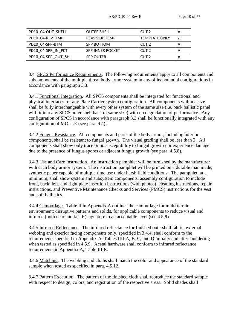
3.3.1.1 Base SPCS and Components (sizes XS, S, MD, LG, XL, 2X).
Piece Name Piece Category Piece Description Fabric
PD10_04-FOS_REV_TMP FOS REVERSE TEMP TEMPLATE ONLY A
PD10_04-FRT_IN_SH_UP FRONT INNER SHELL UP CUT 1 A
PD10_04-FRT_IN_SH_LW FRONT IN SHELL LOW CUT 1 A
PD10_04-FRONT_FLAP FRONT FLAP CUT 1 A
PD10_04-FRNT_FLAP_IN FRONT FLAP IN CUT 1 A
PD10_04-FOS_QR_FLAP QUICK RELEASE FLAP CUT 1 A
PD10_04-FOS_QR_PKT QUICK RELEASE POCKET CUT 1 A
PD10_04-FRNT_FLP_PKT FR FLAP POCKET CUT 1 A
PD10_04-FRT_IN_P_PKT FR IN PLATE POCKET CUT 1 A
PD10_04-FSH_CVR_NCK FRONT SHLDER CVR NEK CUT 2 A
PD10_04-FSH_CVR_ARM FRONT SHLDER CVR ARM CUT 2 A
PD10_04-BOS BACK OUTER SHELL CUT 1 A
PD10_04-BISU BACK INNER SHELL UPP CUT 1 A
PD10_04-BISL BACK INNER SHELL LOW CUT 1 A
PD10_04-BACK_CTR_FLP BK CENTER FLAP OUTER CUT 1 A
PD10_04-BK_CTRFLP_IN BK CENTER INNER FLAP CUT 1 A
PD10_04-BCK_CH_CVR BACK CHANNEL COVER CUT 2 A
PD10_04-B_CH_PL_TM B CH PLASTIC TEMPLET TEMP- CUT 2 P
PD10_04-BK_CTRFLP_PK BK CENTER FLAP POCK CUT 1 A
PD10_04-BCK_PKT_FLAP BK POCKET PLATE FLAP CUT 1 A
PD10_04-BCK_PLT_PKT BACK PLATE POCKET CUT 1 A
PD10_04-F_SHL_DR_T FR SHL D RING TEMPLE TEMP- CUT 2 W
PD10_04-FB_FLAP_ST FR BK FLAP STRAP TEM TEMP- CUT 2 W
PD10_04-FB_INPL_PS F B IN PL PK STRAP T TEMP- CUT 2 W
PD10_04-F_SHL_BK_ST F SHL BK STR T TEMP- CUT 2 W
PD10_04-QR_HNDL_T QUICK REL WEB-TEMPLE TEMP- CUT 1 W
PD10_04-SPC_CFSTRT CF STRAP BUCKLE TEMP TEMP- CUT 2 W
PD10_04-IN_SHELL INNER SHELL CUT 2 A
PD10_04-PLAST_BALSTC PLAST BALLISTIC CUT 2 B
AR/PD 10-04 Rev E Page 10 of 77
PD10_04-OUT_SHELL OUTER SHELL CUT 2 A
PD10_04-REV_TMP REVS SIDE TEMP TEMPLATE ONLY Z
PD10_04-SPP-BTM SPP BOTTOM CUT 2 A
PD10_04-SPP_IN_PKT SPP INNER POCKET CUT 2 A
PD10_04-SPP_OUT_SHL SPP OUTER CUT 2 A
3.4 SPCS Performance Requirements. The following requirements apply to all components and
subcomponents of the multiple threat body armor system in any of its potential configurations in
accordance with paragraph 3.3.
3.4.1 Functional Integration. All SPCS components shall be integrated for functional and
physical interfaces for any Plate Carrier system configuration. All components within a size
shall be fully interchangeable with every other system of the same size (i.e. back ballistic panel
will fit into any SPCS outer shell back of same size) with no degradation of performance. Any
configuration of SPCS in accordance with paragraph 3.3 shall be functionally integrated with any
configuration of MOLLE (see para. 4.4).
3.4.2 Fungus Resistance. All components and parts of the body armor, including interior
components, shall be resistant to fungal growth. The visual grading shall be less than 2. All
components shall show only trace or no susceptibility to fungal growth nor experience damage
due to the presence of fungus spores or adjacent fungus growth (see para. 4.5.8).
3.4.3 Use and Care Instruction. An instruction pamphlet will be furnished by the manufacturer
with each body armor system. The instruction pamphlet will be printed on a durable man made,
synthetic paper capable of multiple time use under harsh field conditions. The pamphlet, at a
minimum, shall show system and subsystem components, assembly configuration to include
front, back, left, and right plate insertion instructions (with photos), cleaning instructions, repair
instructions, and Preventive Maintenance Checks and Services (PMCS) instructions for the vest
and soft ballistics.
3.4.4 Camouflage. Table II in Appendix A outlines the camouflage for multi terrain
environment; disruptive patterns and solids, for applicable components to reduce visual and
infrared (both near and far IR) signature to an acceptable level (see 4.5.9).
3.4.5 Infrared Reflectance. The infrared reflectance for finished outershell fabric, external
webbing and exterior facing components only, specified in 3.4.4, shall conform to the
requirements specified in Appendix A, Tables IIII-A, B, C, and D initially and after laundering
when tested as specified in 4.5.9. Acetal hardware shall conform to infrared reflectance
requirements in Appendix A, Table III-E.
3.4.6 Matching. The webbing and cloths shall match the color and appearance of the standard
sample when tested as specified in para. 4.5.12.
3.4.7 Pattern Execution. The pattern of the finished cloth shall reproduce the standard sample
with respect to design, colors, and registration of the respective areas. Solid shades shall

AR/PD 10-04 Rev E Page 11 of 77
demonstrate level dyeing uniformity. The pattern of the cloth shall match the pattern for
Operation Enduring Freedom Camouflage Pattern (OCP).
3.4.8 Colorfastness. The printed finished cloth shall show fastness to laundering (after 3 cycles),
light (after 40 standard fading hours or 170 kilojoules), and perspiration equal to or better than
the standard sample or 3-4 of the AATCC Gray Scale for Color Change and Color Transfer for
each of the pattern areas, except fastness to light shall be equal to or better than a rating of 3 for
Color Change. The finished cloth shall show fastness to crocking equal to or better than the
standard sample or shall have an AATCC Chromatic Transference Scale rating of not lower than
3-4 for all the pattern areas. The finished textile components shall meet the colorfastness
requirements when tested as specified in para. 4.5 (Appendix C, Table I).
3.5 SPCS Subsystem. See paragraph 3.3 for SPCS subsystem configuration. The maximum
finished weight of the Plate Carrier subsystem components for each size is outlined in Appendix
A, Table IV-A when measured as specified in 4.5.6. The minimum area of ballistic coverage for
each ballistic panel subcomponent in each size is outlined in Appendix A, Table IV-B when
tested as specified in 4.5.5. Finished base vest measurements for each size are outlined in
Appendix A, Table IV-C and IV-D when inspected as specified in para. 4.5.2.
3.5.1 Ballistic Protection Levels. The SPCS protection levels follow (see paragraphs 4.1, 4.4, &
4.6):
a) SPCS provides fragmentation protection from conventional fragmenting munitions (see
para. 3.5.2.2).
b) SPCS provides handgun protection for 9mm, 124 gr., Full Metal Jacketed (FMJ) projectile
(see para. 3.5.2.3)
c) SPCS and ESAPI/ESBI (see para. 3.5.2.4, 3.7) together provide multi-hit small arms
protection from:
(1) Threat (E)
d) SPCS and XSAPI/XSBI (see para. 3.5.2.4, 3.7) together provide multi-hit small arms
protection from:
(1) Threat (E)
(2) Threat (X)
3.5.2 Ballistic Performance. The SPCS ballistic material system consists of an outershell,
ballistic panel, and an outershell inner lining to accomplish the ballistic characteristics specified
in paragraphs 3.5.2.2/3/4 as tested in paragraph 4.6.
3.5.2.1 Removable Ballistic Panel Subcomponent. Ballistic panels must be able to be inserted
easily into SPCS outershell carriers; front and back base vest, side pouches and cummerbund
pouch. The ballistic panels shall provide a means to prevent raveling and soiling, and to secure
placement properly within the outershell carrier. The gap/ease between outershell carrier and
panel shall be no greater than the ease allowed within the baseline patterns (see para. 4.5.1).
AR/PD 10-04 Rev E Page 12 of 77
3.5.2.1.1 Ballistic filler. The ballistic filler (without stitching and the ballistic insert cover)
weight shall not exceed 0.88 lb/ft2
with a maximum thickness (without the ballistic insert cover)
of 0.30 inches when tested as specified in paragraphs 4.5.6 and 4.5.7. Not to exceed 0.92 lb/ft2
with insert cover. Except for ancillary components such as thread, the ballistic filler shall be
made entirely of ballistic material. Each ballistic filler layer shall be water repellent.
Additionally, all components of the SPCS must use the same ballistic package.
Ballistic material for a specific lot will be limited to that particular lot with the following
exception: in the case where a roll of significant length remains, that particular roll may be used
in the next consecutive lot. Under no circumstances shall ballistic material from a particular roll
be used on more than two (2) lots.
3.5.2.1.2 Flexibility. The ballistic filler shall be flexible.
3.5.2.2 SPCS Fragmentation Protection. The ballistic material system (see para. 3.5.2) shall
provide consistent ballistic performance for each complete SPCS (ballistic inserts for base vest
front and back, side plate pockets, and cummerbund). All SPCS components and base vest (see
para. 3.3) will be made from the same approved ballistic package. Appendix B, Table I lists the
required minimum V50 values for base vest assembly and side plate panels at specified obliquity
when tested with the 17-grain Fragment Simulating Projectile (FSP).
Appendix B, Table I specifies minimum ballistic performance that shall be maintained after
conditioning to hot and cold temperature extremes, accelerated aging and POL contamination.
Testing is specified in section 4.5. Any change in the SPCS area of coverage must meet
minimum casualty reduction potential of the approved system coverage (see section 3.5,
Appendix A, Table IV-B) and V50 performance (see Appendix B, Table I) stated herein. Any
product improvements in the ballistic performance of the SPCS base vest panels, side plate
pocket panels and/or cummerbund panels shall not reduce the ballistic performance of the SPCS
when tested with ESAPI/XSAPI and ESBI/XSBI as specified in the performance requirements
(see 2.2).
3.5.2.3 Handgun protection. The ballistic material system shall be engineered to provide handgun
protection. Appendix B, Table III outlines the ballistic material system minimum V50, and V0
acceptance for the 9-mm, 124-grain, Full Metal Jacketed (FMJ) projectile against 3 hits at 0 degree
obliquity and 2 hits at 30 degree obliquity with maximum deformation when tested as specified in
4.6.
3.5.2.4 Small Arms Protection. The ballistic material system shall be engineered to provide small
arms protection when the base SPCS material system is used in conjunction with ESAPI/XSAPI
and ESBI/XSBI. Appendix B, Table II outlines the ballistic material system minimum dry V0
acceptance as specified in section 4.6. The classified threat code to specific threat round
correlation chart and other details are provided in a classified enclosure separately provided to
those vendors with proper security clearances and facility clearance through DSS.
3.5.3 SPCS Construction. The exterior of the system shall be edge stitched 1/8 inch from all
edges EXCEPT for edges indicated with corresponding location markings on the patterns
provided. All stitching shall be back-tacked to prevent raveling and demonstrate good stitching

AR/PD 10-04 Rev E Page 13 of 77
quality with no loose ends, consistent stitches per inch, even tension with no loose needle or
bobbin thread. Fabric edges shall not ravel.
3.5.3.1 Hook and Loop Fastener. Hook and loop fasteners shall not be stitched in the selvage
edge to prevent associated fraying durability problems in repeated use (see para. 4.5).
3.5.3.2 Stitching. Stitching shall conform to ASTM D-6193, 9-12 stitches per inch. End of seams
and stitches (stitch type 301) that are not caught in other seams or stitching shall be securely
back tacked or back stitched. Thread breaks or bobbin run-outs occurring during sewing shall be
secured by stitching back of the break minimum of 1/2 inch. Thread tension shall be maintained
so that there will be no loose stitching resulting in loose bobbin or top thread, or excessively high
stitching resulting in puckering of the materials sewn. Thread ends shall be trimmed to a length
of not more than 1/4 inch.
3.5.3.3 Automatic Stitching. Automatic stitching machines may be used to perform any of the
stitching patterns provided the requirements for the stitch pattern, stitches per inch, size and type
of thread are met, and at least three or more tying, overlapping, or back stitches are used to
secure the ends of the stitching.
3.5.3.4 Bartacks. No stitch run-off is allowed and no needle cutting by bartack. Double bartacks
(one on top of the other) will be avoided to prevent needle cutting and weakening of the
attachment point. Bartack requirements are specified in Appendix A, Table V when tested as
specified in 4.5.
3.5.3.5 Bartack Alignment for MOLLE Pocket Attachment. The required spacing of vertical
bartacks is specified below which is needed for physical compatibility of MOLLE pocket
attachment on SPCS base vest.
a) Distance between vertical bartacks on horizontal webbing shall be 1 1/2”
–0, +1/16”.
b) Distance between horizontal webbing shall be 1 1/8” (±1/16).
c) Vertical bartacks on consecutive horizontal webbing rows shall be vertical
aligned bottom to top in a vertical straight line.
3.5.3.6 Buttonholes. Buttonholes shall be straight cut. Position in accordance with the marks
indicated on the pattern, with the ends of the buttonholes securely tacked. All buttonholes will
be 1 ¼” with a finished cut of 1”+ 1/16”.
3.5.3.7 Drag strap. The drag strap on the back of the SPCS carrier (all sizes) shall have a peak
strength not less than 400 lbs (increased strength is desirable) when tested in accordance with
paragraph 4.8, and also give rise 1/4 inch -0/+1/8.
3.5.3.8 Emergency Release Mechanism. An emergency release mechanism shall be provided
(para. 3.2.7). The mechanism shall be a single point activator and located on the front (chest)
portion of the vest and be capable of being operated with either hand, gloved or not. Upon
activation of the mechanism, the vest shall separate into two distinct pieces. The SPCS release
mechanism must be compatible with the Tactical Assault Panel (TAP) and cummerbund.

AR/PD 10-04 Rev E Page 14 of 77
3.6 Size, Identification, and Instruction Label. All markings must be visible in low light levels
under .0108 lux lighting and also in blackout conditions with an L-shaped standard Army issued
flashlight with a red or blue filter. The label shall be of sufficient strength to withstand repeated
abrasion during field use and cleaning, and include the following:
a) The SPCS base vest component shall have a combination of size, identification, serial
number, ballistic protection level, and instruction label for the base vest (Appendix E).
Chest circumferences for each size in Appendix A, Table VI.
b) The side pocket and cummerbund shall have a combination of size, identification, serial
number, and ballistic protection level for the side plate pocket and cummerbund
(Appendix E).
c) The instruction label shall include dos and don’ts for use and cleaning instructions, and
donning/doffing instructions for the entire SPCS.
d) The instruction label shall be located on the inside of the back of the base vest (Appendix
E). The size of the label shall be 4.5 inches wide by 7.75 inches high. The type shall be
no smaller than 10 point and shall be in accordance with MIL-DTL-32075, Type VI, and
Class 14. Color: Tan 499. Contents of labels shall be as found in 6.6.
3.6.1 Unique Identification (UID): Front and Back ballistic panels only will require a unique
identification label that conforms to the specifications below:
The manufacturer is required to comply with the current versions of Military Standard 130 and
the Department of Defense Guide to Uniquely Identifying Items, and the following criteria.
1. Color: Label/Tag will be Foliage Green 504 with black Human Readable and Machine
Readable Information (HRI) and (MRI).
2. HRI shall consist of: Commercial and Government Entity (CAGE) code of activity
applying the tag/label, Lot Number, Serial Number, Date of Production, National Stock
Number (NSN) and Design Code. HRI will meet requirements of the latest version of
MIL-STD-130.
3. MRI shall consist of one ECC 200 compliant Data Matrix code containing: CAGE code
of activity applying the tag/label, Lot Number, Serial Number, Date of Production, NSN,
and Design Code. The tag/label shall comply with the latest version of MIL-STD-130,
ANSI MH10.8.2, and Items #4 and #5 below. To prevent automated read errors, the
Government will not allow other 1D or 2D codes to be printed on this label. This does
not restrict contractor from using other HRI and MRI on labels not associated with the
UID label/tag.
4. Data Matrix Construct: The Data Matrix shall be encoded per MIL-STD-130 using only
the data identifiers (DI) and criteria shown below. The following DI sequence shall be
maintained in the order listed below:

AR/PD 10-04 Rev E Page 15 of 77
Cage=17V followed by cage code
Lot=1T followed by lot number
Serial number=S followed by serial number
Date of production = 16D followed by production date, YYYYMMDD
National stock number=N followed by the NSN.
Part number = 1P followed by design code (the design code may be up to 13 alpha-
numeric characters (plus only dashes “-” as special characters))
Construct Example:
[)>RS06GS17V52969GS1TE034GSS328185GS16D20080215GSN8470-01-520-
7370GS1PABC-123RSEOT
5. Data Matrix Geometry: Data Matrix codes shall be a square ECC200 matrix per ISO
16022. Individual Cell size (element size) of the code shall be between 0.020 and 0.023
inches. A quiet zone of 0.5 inches of Black label/tag material is required around the Data
Matrix code.
6. Verification: Data Matrix code quality will be graded to ISO 15415 with a certified
verifier and meet a minimum passing grade per the latest release of MIL-STD-130.
AS9132 and AIM DPM grading platforms will not be allowed for this project.
Contractor must provide the contracting officer with at least two verification reports per
ballistic panel for each FAT and LAT. If using laminates or overcoats the label must be
verified after placing the laminate or overcoat on the label or tag. No exceptions are
allowed. Proof of Verification is subject to inspection at the time of shipment.
7. Validation: Validation checks of the UID must be performed on a routine basis.
Contractor is responsible for encoding the UID per above guidelines (#4 and 5) and the
latest revision of MIL-STD-130. Proof of Validation is subject to inspection at the time
of shipment.
8. Placement of the UID label/tag: The data will be centered horizontally and shall be
placed on the same label for size, identification, and instruction (specified in 3.6). The
UID label/tag will be located directly below all the information specified in 3.6.
3.7 Hard Armor Pocket. The SPCS ESAPI/XSAPI/ESBI/XSBI pockets shall ensure positioning
of the bottom horizontal edge according to the Government patterns for proper organ coverage,
and have enough ease to allow the ESAPI/XSAPI/ESBI/XSBI to be easily and quickly inserted
into and removed from the vest without struggle or force. The ESAPI/XSAPI pocket shall
ensure that along the entire perimeter of the insert there is 1 in -0/+1/8 inch of ballistic filler that
extends beyond the edge of the corresponding size insert for all sizes (see paragraph 4.7.2). The
ESBI/XSBI pocket shall allow for edge to edge coverage of soft armor coverage on the
ESBI/XSBI plate. The ESAPI/XSAPI/ESBI/XSBI pocket shall not allow the insert to shift
during user operation or due to added weight of MOLLE components attached to the outershell.
(see paragraph 4.7.1)).
3.8 Ownership and Support.

AR/PD 10-04 Rev E Page 16 of 77
3.8.1 Service Life and Reliability. The finished SPCS shall have a service life of 365 days of
continuous use in all types of typical military field environments with no operational mission
failures if not impacted by ballistic projectiles.
3.8.2 Shelf Life. The minimum shelf life of all components and materials in the finished SPCS
shall be 5 years. The components and materials shall suffer no degradation in performance after
storage for a period of 5 years.
In addition, the contractor and its subcontractor shall ensure that the finished end item shipped,
following Government LAT approval, in a timely manner to ensure that no less than 90 percent
(allowing for rounding to whole months) of the shelf-life is still remaining at time of receipt by
the first Government activity. Any delivery from a contractor not having at least 90 percent
shelf-life remaining shall be considered nonconforming and cause for rejection.
The Contractor and its subcontractors shall not incorporate, integrate nor include in the
manufacturing of any subassembly or end item, self-life expired raw materials, and or parts. If
shelf-life expiration for raw materials is not defined in this specification, the recommended shelf-
life expiration from the raw material source shall be honored. Any delivery or end item found to
have been manufactured with expired material from a contractor shall be considered non-
conforming and cause for rejection.
3.8.3 Health and Safety. The SPCS shall be safe to use and not contain any harmful materials.
3.8.4 Safety. The SPCS shall be designed so that under all conditions or normal use and under a
likely fault condition, including human error, it protects against the risk of hazards. The
potential for injury while assembling, donning/doffing, cleaning and maintaining the SPCS shall
be eliminated or minimized to the maximum extent. There shall be no loose parts that would be
susceptible to snagging.
3.8.5 Toxicity. The water repellant/frame finished on SPCS shall not present a dermal health
hazard when used as intended.
3.8.6 Hazardous Materials. Hazardous materials that can be exposed to personnel or the
environment during any operational (to include fabrication, transportation, and setup/tear down)
or maintenance procedures, or exposed as a result of damage to the equipment, or requiring
special disposal procedures, shall be kept to an absolute minimum, consistent with operational
requirements. Environmentally acceptable substitutes shall be used whenever possible without
degrading operational function and maintaining cost effectiveness. Hazardous material exposure
to personnel shall be controlled to levels below the OSHA Permissible Exposure Limits. The
SPCS shall not present any uncontrolled health hazard throughout the life-cycle of the item. The
following shall be included when designing the SPCS.
Avoid the use of materials that cause skin irritation or allergies
Utilize materials that are resistant to fire, fungus, bacterial growth and etc.
Allow for easy cleaning and/or replacement of parts that could present health hazards to
the wearer.
AR/PD 10-04 Rev E Page 17 of 77
3.8.7 Responsibility for compliance. All items shall meet all requirements of section 3 and 4 of
this specification. The absence of any inspection requirements shall not relieve the contractor of
the responsibility of ensuring that all products of supplies submitted to the government for
acceptance shall comply with all requirements of the contract. Sampling inspection, as part of
manufacturing operations, is an acceptable practice to ascertain conformance to requirements;
however, this does not authorize submission of known defective material, either indicated or
actual, nor does it commit the government to accept defective material. If there is a conflict
between the stated requirements and the ANSI standard, the more restrictive requirement shall
apply.
4. VERIFICATION
4.1 Classification of Inspections. The inspection requirements specified herein are classified as
outlined below. Unless otherwise specified, the contractor is responsible for the performance of
all inspection requirements specified herein. The Government reserves the right to perform any
of the inspections set forth where such inspections are deemed necessary to ensure the supplies
conform to prescribed requirements.
a) PVT (see 4.2)
b) FAT (see 4.2)
c) LAT (see 4.3)
4.2 Product Verification Testing and First Article Testing. Product verification testing is
required prior to FAT submittal and must be tested at a Government facility. Production
verification testing shall be tested in accordance with section 4.6 and Appendix C and D. Failure
to meet the ballistic requirements outlined within this purchase description will prohibit the
armor design from entering FAT. Additionally, the contractor shall provide data that shows all
the components and materials used in SPCS meet all stated requirements of the Technical Data
Package. When a FAT is required, it shall be examined for design (3.3), compatibility and
interchangeability of components, inspection requirements in (4.5), ballistic data for all test
conditions (4.6.1.1), data, certificate, or compliance for testing requirements in 4.6 and 4.7, and
overall workmanship (Appendix A, B, C, D & E).
4.2.1 Material Qualification. At any point after a First Article Test has been approved, any
material change must be submitted to the Govt. via the ECP process. The Govt. will then
communicate requirements for approval.
4.2.2 Ballistic Qualification. At any point after a First Article Test has been approved, any
material change must be submitted to the Govt. via the ECP process. The ballistic package will
be required to pass all ballistic First Article Test requirements as specified in paragraph 4.6.
Each ballistic package submitted for a First Article Test shall have a unique name or code to
identify the package. No duplication of names or codes for different packages shall be accepted.
A ballistic package includes both base vest and side panel designs.

AR/PD 10-04 Rev E Page 18 of 77
4.3 Lot Acceptance Testing. LAT shall be performed in accordance with Section 3 and 4 in
conjunction with Appendices A, B, C, D, E and F. The Government’s acceptance of the
contractor’s end item product will be determined by the ballistic and non-ballistic requirements
validation.
4.3.1 Certificate of Compliance (COC). When certificates of compliance are required, the
Government reserves the right to test such items to determine the validity of the certification.
All certificates shall be supported by test reports to ascertain their validity.
4.4. Demonstration Verification. The performance requirement is verified by observation and
operation that the properties, characteristics and parameters of the item meet the functional
requirements specified in applicable paragraphs of Section 3. Pass or fail criteria are simple
accept or reject indications of functional performance and can be found in Appendix C.
4.5 Non Ballistic Requirements and Verifications. Appendix C, Table I delineates performance
requirements verified through visual methods, including physical measurements in order to
determine that no deficiencies exist.
4.5.1 End Item Visual Inspection. The end items shall be inspected for the defects listed in
Appendix C, Table II. The lot size shall be expressed in units of vests or the individual
components (when component is purchased separately). The sample unit shall be one
completely fabricated vest or individual component.
4.5.2 End Item Dimensional Inspection. The end items shall be inspected for finished
measurements (see Appendix C, Table III). The lot size shall be expressed in units of vests or
individual components (when component is purchased separately). The sample unit shall be one
completely fabricated base vest or individual component.
4.5.2.1 Linear Measurements. Front and back center measurements are taken along the center
line by holding the garment taut. With a metal measuring device, measurements shall be taken to
the nearest 1/16 inch. Front and back width, and webbing hanger's measurements are taken in a
flat, relaxed state, with a metal measuring device and measurements taken to the nearest 1/16
inch. ESBI/XSBI pocket measurements are taken along the horizontal and vertical line by
holding the garment taut. With a metal measuring device, measurements shall be taken to the
nearest 1/16 inch. Dimensional measurements are taken as described below:
a) Center Front and Back Lengths: The center front and back length shall be taken on a
straight line from the center of the back from the top edge of the base vest neckline
(center front and back) to the bottom edge of the shell.
b) Front and Back Width: The front and back width shall be taken on a straight line
measuring across the panel from side to side.
c) Spacing of Webbing Hangers for MOLLE pockets: The horizontal distance between
bartacks shall be taken from the center of one bartack to the center of the adjacent

AR/PD 10-04 Rev E Page 19 of 77
bartack. The spacing between horizontal webbing shall be measured on adjacent
webbings from the bottom edge of one to the top edge of the other.
d) ESBI/XSBI Side Pocket Length and Width: The side ESBI/XSBI plate pocket
measurements shall be taken on a straight line along the outer edge of the pocket on both
horizontal and vertical axis.
e) Cummerbund Length and Width: The cummerbund measurements shall be taken on a
straight line along the outer edge of the pocket on both horizontal and vertical axis.
4.5.3 In-Process Visual Examination of Cut Parts, Fillers and Patterns. The cut parts for the vest
shell assembly, and the ballistic filler components shall be 100 percent inspected by vendor
during the cutting process to determine that parts containing defects such as a hole, cut, are
removed from production. Ballistic fillers shall be 100 percent inspected by vendor during the
assembly of the individual groups to assure that they contain the correct number of plies, that no
individual plies are pieced and they are marked correctly as to the size and number of plies. In
addition to the above, inspection shall be made of working patterns to assure that they conform
to government patterns in all respects.
4.5.4 In-process Visual Examination of Ballistic Filler Assemblies for Size. Appendix C, Table
IV provides visual examination criteria for ballistic filler. The lot shall be expressed in units of
front and back ballistic fillers and ESBI/XSBI side plate pocket ballistic fillers. The sample unit
shall be one ballistic filler.
4.5.5 Area of Coverage. Square inches of coverage are measured by digitized patterns and
comparison to working patterns (para 3.5).
4.5.6 Weight and Areal Density.
4.5.6.1 Weight Measurements. The SPCS will be examined for weight by component. See
maximum weights in Appendix A, Table IV-A. Weights are taken on a tarred scale and
measured to the nearest 0.01 pound.
4.5.6.1 Areal Density Measurements. Areal density shall be calculated on unstitched ballistic
filler material in accordance with ASTM-D-3776, Standards Test Methods for Mass per Unit
Area of Fabric, Option C, with exceptions. Each 15 inch x 15 inch ply of ballistic filler shall
have two (2) 100 cm2 die cut samples cut out and weighed independently to the 0.001 lbs. The
weight percent difference between the first sample and the second sample shall be within two (2)
percent. The areal density for a single ply shall be the total mass of the two (2) pieces divided by
the total area of the two (2) pieces. The actual areal density for the entire ballistic filler shall be
calculated by adding each ply’s areal density together. Areal densities shall be expressed in
lb/ft2.
4.5.7 Thickness. Thickness is measured to the nearest 0.01 inch when measured under 0.5 psi
when tested according to ASTM D-1777 (Appendix A Table I).

AR/PD 10-04 Rev E Page 20 of 77
4.5.8 Fungus Test. Verification of compliance with the fungus requirement will be performed
through the use of certified materials and coupon sampling. A fungus test will be performed on
all non-certified materials. Tests will be performed in accordance with Method 508.6 of MIL-
STD-810. A sample of each non-certified material will be placed in the fungus test chamber for
28 days.
4.5.9 Infrared Reflectance. Spectral reflectance shall be evaluated initially and after laundering
In accordance with Appendix A, Table III. The accelerated three laundering shall be performed
using AATCC 61 Test No. 1A; except a 4 gram sample size shall be used unless the amount
needed to provide the required five layers of the specimen for testing is larger (the specimens of
webbing or tape need to be 4 inches long). When evaluating the camouflage printed cloth,
webbing, or tape each color shall be tested separately. Also AATCC Standard Reference
Detergent without optical brightener shall be used. Spectral reflectance, initially and after
laundering, will be obtained from 600 to 860 nanometers (nm), at twenty (20) nm intervals on an
integrating sphere spectrophotometer or a spectroradiometer. The calibration of the instrument
shall be traceable to the National Institute of Standards and Technology Perfect Reflecting
Diffuser Calibration as stated in a Certificate of Traceability supplied by the instrument
calibration standards. The spectral bandwidth shall be less than 26 nm at 860 nm. Reflectance
measurements may be made by either the monochromatic or polychromatic mode of operation.
When the polychromatic mode is used, the spectrophometer shall operate with the specimen
diffusely illuminated with the full emission of a source that simulates either CIE Source A or
CIE Source D65. Measurements will be taken on a minimum of 2 different areas and the data
averaged. The specimen shall be viewed at an angle no greater than 10 degree from normal, with
the specula component included. Photometric accuracy of the spectrophotometer shall be within
1 percent, and wavelength accuracy within 2 nm. The standard aperture size used in the color
measurement device shall be 1.0 to 1.25 inches in diameter unless the size of the item dictates a
smaller aperture is required. When the measured reflectance values for any color at four or more
wavelengths do not meet the limits specified in Appendix A, Table III, it shall constitute a test
failure.
4.5.10 Resistance to POL, insect repellent, sweat, and sea water after one laundering. SPCS
outershell carrier cloths shall be tested, after one laundering per 4.5.11, and after exposure to
each DEET, POLs; motor oil, JP-8 and weapon lubricant, sweat, and sea water for hydrostatic
resistance in accordance with AATCC TM 127. A specimen for each test liquid (i.e., DEET,
motor oil, etc) shall be 8 inches by 8 inches. The specimen shall be laid flat, face side up, on a
glass plate, 8 inches by 8 inches by ¼ inch and three drops of each test liquid shall be applied to
the center of the specimen. A glass plate the same dimensions shall be placed on the specimen
and a four pound weight placed in the center of the glass plate assembly. After 16 hours, remove
the specimen and test immediately for hydrostatic resistance. DEET test liquid shall be
diethyltoluamide (O-I-503 Type II, Concentration A). The motor oil shall conform to ASTM D-
4485, Grade CD-II. The weapon lubricant shall conform to MIL-PRF-63460 or commercial
Break Free CLP, Santa Ana, CA or equal. The perspiration solution shall be made up in a 500
ml glass beaker by combining 3.0 grams sodium chloride, 1.0 gram of trypticase soy broth
powder, 1.0 gram normal propyl propionate, and 0.5 gram liquid lecithin. Add 500 ml of
distilled water, add a magnetic stirring bar, and cover the beaker. Place the beaker on a
combination hot plate/magnetic stirrer apparatus. While stirring, heat the solution to 50 degree C
until all ingredients are dissolved. While stirring, cool the solution to 35 degree C, remove
AR/PD 10-04 Rev E Page 21 of 77
cover, and dispense immediately with pipette or other suitable measuring device. Dispense 2 ml
of perspiration solution at 35 degree C onto the center of an 8 inch by 8 inch by 1/4 inch glass
plate. Place an 8 inches by 8 inches specimen face up. Dispense an additional 2 ml of
perspiration solution onto the center of the specimen. A glass plate (do not rinse) of the same
dimensions shall be placed on the specimen and a four pound weight placed in the center of the
glass plate assembly. After 16 hours, remove and air dry specimen before testing for hydrostatic
distance. See 4.6.1.1.1 for sea water formulation and sample preparation shall be the same as
perspiration.
4.5.11 Laundering Procedure. The test specimens and ballast, if needed, shall be placed in an
automatic washing machine set on permanent press cycle, high water level and warm (105
degree F +/- 5 degree F) wash temperature. The test specimens shall be taken from the vicinity
of the fabric as the specimens for the initial test. The test specimens shall be laundered with 0.5
ounce (14 grams) of 1993 AATCC Standard Reference Detergent. The duration of the
laundering cycle shall be 30 +/-5 minutes. After laundering, the specimens and ballast shall be
dried in an automatic tumble dryer set on permanent press cycle, 150 to 160 degree F for
approximately 15 minutes. The laundering equipment, washer and dryer, shall be in accordance
with AATCC TM 135-1992.
4.5.12 Visual Shade Matching. The color and appearance of the cloths and components
(webbing, tapes) shall match the standard sample using the AATCC Evaluation Procedure 9,
Option A or C, with sources simulating artificial daylight D75 illuminant with a color
temperature of 7500 (± 200) K, illumination of 100 (± 20) foot candles, and shall be a good
match to the standard sample under incandescent lamplight at 2856 (± 200) K. All
matching/shade analysis must be conducted in a Government directed lab unless otherwise
specified in the contract or procuring documents.
4.5.13 Flame Resistance. All materials tested shall be tested in accordance with ASTM D 6413
in both the warp and fill directions as evaluated by section 3.2.1.1.
4.6 Ballistic Performance. First Article Testing will be conducted on material end items. Lot
Acceptance Testing will be conducted on the end item constructed of the approved ballistic
material system as verified by FAT. Failure to meet the requirements of any sub-test will
constitute failure for the entire FAT or LAT.
4.6.1 Ballistic Testing. General procedures and requirements are provided in 4.6.2 (see 6.4 for
definitions).
4.6.1.1 Conditions. Dry specimens and specimens after wet, hot temperature, cold temperature,
accelerated aging and POL conditioning will be ballistically tested as specified in 3.5.2. Prior to
conditioning, the heat sealed ballistic cover will be carefully cut along the entire bottom edge of
the ballistic panel without cutting into the ballistic filler. All testing will be conducted in the
conditions specified in 4.6.2.3. All non-ballistic components of the ballistic material system
(i.e.; outer shell and inner lining) shall be laundered as specified in 4.5.11 prior to assembling
test panels to simulate a worn condition. All specimens will be visually inspected after
conditioning for coloration, distortion, melting, cracking, or other physical defects and noted.

AR/PD 10-04 Rev E Page 22 of 77
4.6.1.1.1 Wet Condition. Sea water shall be utilized for wet test conditions. Prior to
conditioning, the heat sealed ballistic cover will be carefully cut along the bottom edge of the
ballistic panel without cutting into the ballistic filler, from edge to edge. Sea water formulation
is 3% sodium chloride / 0.5% magnesium chloride. The armor submersion equipment shall
consist of a water bath that allows for at least one armor panel of the largest size to hang
vertically, without any folds or bends, with the top edge of the armor at least 100 mm (3.9 in)
below the surface of the water, and with at least 50 mm (2.0 in) clearance around the panel for a
minimum of 24 hours but should not exceed 24.5 hours. The water temperature shall be 70
degree F ± 10 degree F. For armors that are buoyant, as little weight as possible shall be
attached to the bottom edge of the armor with clothes pins or similar clips to allow the armor to
hang vertically (cut side down) under water. After removing the specimen from the water, it
shall be hung vertically and allowed to dry for 10 min (+5 min/-0 min) and tested within 5
minutes with tests completed within 60 minutes.
4.6.1.1.2 Temperature Extremes Condition. Prior to conditioning, the heat sealed ballistic cover
will be carefully cut along the bottom edge of the ballistic panel without cutting into the ballistic
filler, from edge to edge. For hot temperature extreme, the SPCS shall be heated in an oven
operating at 155 + 10 degrees Fahrenheit for 6 +/- ¼ hours continuously. The test specimen shall
be removed from the oven, mounted and ballistically tested as specified in 4.6.3. For cold
temperature extreme, the test specimen shall be cold temperature exposed to -60 +/-10 degree F
for 6 +/- ¼ hours continuously. The test specimen shall be removed from refrigeration, mounted
and ballistically tested as specified in 4.6.3, within 10 minutes with tests completed within 60
minutes. If either test is not completed within 60 minutes the specimen shall be reconditioned
for at least 1 hour at the temperature specified above.
4.6.1.1.3 Accelerated Aging. Prior to conditioning, the heat sealed ballistic cover will be
carefully cut along the bottom edge of the ballistic panel without cutting into the ballistic filler,
from edge to edge. Accelerated aging for the SPCS and/or subcomponents will be performed in
general accordance with ASTM D1149, with the following modifications. The entire SPCS or
subcomponent under test will be subjected to treatment. All tested components will be
conditioned for 72 hours at 40oC while maintaining a minimum of 50 parts per hundred million
of ozone. The SPCS and/or subcomponents do not require any additional tensile strain during
accelerated aging conditioning. After accelerated aging conditioning, the SPCS and/or
subcomponents under test must remain at ambient atmospheric conditions for a minimum of 24
hours prior to ballistic testing, not to exceed 36 hours from completion of conditioning. Verify
that the conditioned specimens perform as specified in 3.5.2.2.
4.6.1.1.4 POL Contamination. Prior to conditioning, the heat sealed ballistic cover will be
carefully cut along the bottom edge of the ballistic panel without cutting into the ballistic filler,
from edge to edge. POL conditioning should be done on each of the following; motor oil and JP-
8. The armor submersion equipment shall consist of a POL bath that allows for at least one
armor panel of the largest size to hang vertically, without any folds or bends, with the top edge of
the armor at least 100 mm (3.9 in) below the surface of the POL fluid, and with at least 50 mm
(2.0 in) clearance around the panel for a minimum of 4 hours but no longer than 4.5 hours at
room temperature. For armors that are buoyant, as little weight as possible shall be attached to
the bottom edge of the armor with clothes pins or similar clips to allow the armor to hang
vertically (cut side down). After removing the specimen from the POL fluid, it shall be hung

AR/PD 10-04 Rev E Page 23 of 77
vertically and allowed to dry for 15 minutes. Excess POL fluid shall be wiped from the surface
to facilitate handling of the specimen. Before mounting in the test fixture, the sample may be
contained in a reseal able plastic bag and mounted to the test fixture to limit exposure to
contaminants and fumes. The specimen then shall be ballistically tested within 30 minutes from
removal in the POL fluid, with testing completed within 60 minutes. If the testing is not
completed within 60 minutes another specimen shall be conditioned as specified above and the
testing shall continue with the second panel.
4.6.2 Ballistic Test Criteria. For all Protection Ballistic Limits (BL); V50, and V0 acceptance
tests the following minimum information is required by the government to validate performance:
a. Armor specimen description including exact materials, thickness, and areal density of
armor system or ballistic system nomenclature, and sizes and weights of all
components.
b. Conditioning of armor specimen.
c. Test projectile with exact nomenclature or threat code when required.
d. Temperature and humidity measurements.
e. Yaw angle.
f. Angles of target obliquity.
g. Velocity measurements of each test shot used to test the armor (regardless of whether
that particular velocity was used in the V50 or V0 determination).
h. Velocity loss and/or corrected striking velocity.
i. PP (Partial Penetration) and CP (Complete Penetration) next to each shot velocity as
determined.
j. Back Face Deformation measurements recorded to the nearest tenth of a millimeter
rounding following standard ASTM E29
k. Angle of spall/debris ejection if applicable.
l. Name of organization/company performing tests.
m. Type of gun barrel and serial number, caliber, and propellant type and weight, twist
rate.
n. Range measurements including distances from gun barrel to velocity measurement
devices and target.
o. Calculated Ballistic Limit. In a situation where the V50 BL, or V0 data sheet would
compromise the Security Classification Guide for Armor Materials (see 2.2), the data
sheet should exclude the specific projectile used during testing.
p. Penetrated plies of soft armor for system tests.
q. Clay drop temperatures, locations, depth and clay box number.
r. Remarks or notes for all testing anomalies, unfair hits, etc.
s. All shot locations.
t. Revision number/level of all ballistic software used by test lab (i.e. FARO software
including smoothing function, etc…).
4.6.2.1 Projectile Velocity Determination. Projectile velocity and time of flight measurements
shall be in accordance with ITOP 4-2-805. Instrumental velocity shall be translated into strike
velocity at the target and the strike velocity shall be used for ballistic requirements. Projectile
velocity measurement methods shall employ either high velocity lumiline screens or electrical
contact screens which either open or close an electric circuit by passage of the projectile through

AR/PD 10-04 Rev E Page 24 of 77
the detector. Contact screens may consist of metallic foils separated by a thin insulating layer, or
may consist of a circuit printed on paper with the circuit spacing such that the projectile passing
through the screen will break the circuit. An electric counter type chronograph measuring to the
nearest microsecond or as a minimum to the nearest 10 microseconds will be used with these
measuring devices. As an alternative, radiographic equipment calibrated to capture the projectile
at various time intervals of flight can be used. For all projectiles, velocity correction
methodology shall be used to calculate the actual striking; ATC V2 Drag curves shall be used to
accomplish this.
4.6.2.2 Weapon Mounting Configuration. The spacing from the weapon muzzle to the first pair
of triggering devices shall be sufficient to prevent damage from muzzle blast and obstruction
from smoke in case optical devices are used. Recommended distances can be found in ITOP 4-
2-805. Spacing between triggering devices is a function of the expected velocity of the projectile
being fired. In many instances, physical restriction, such as short overall distance from muzzle
to test sample dictates the spacing of the triggering devices. The last pair of triggering devices
shall be placed at least four (4) feet (122 cm) for fragment and 9mm tests, and at least 5 feet
(152.4 cm) for system level tests in front of the test sample and should be protected from
possible damage resulting from fragments.
4.6.2.3 Environmental Test Conditions. All ballistic tests shall be performed as closely as
possible to a standard atmosphere of 68 +/- 10 degree Fahrenheit and 50 +/- 20% relative
humidity. Temperature and humidity measurements shall be recorded before the beginning of
days test firings and every two hours thereafter.
4.6.2.4 Projectile Yaw Determination. Projectile yaw shall be measured for each firing by yaw
cards, flash radiograph or photography. Any round for which yaw is determined to be greater
than 5 degrees for soft armor tests and 3 degrees for system tests, shall be disregarded in the
calculation of the ballistic limit. The measurement system employed should be capable of
measuring yaw within an accuracy of 1.0 degrees.
4.6.3 V50 BL Calculation. V50 will be determined in accordance with MIL-STD-662F and ITOP
4-2-805. For First Article Testing (FAT) and Lot Acceptance Testing (LAT), three (3) Partial
Penetration (PP’s) and three (3) Complete Penetrations (CP’s) within a 125 ft/sec velocity spread
or five (5) Partial Penetration (PP’s) and five (5) Complete Penetrations (CP’s) within a 150
ft/sec velocity spread yield the V50 BL determination that will be accepted. For LAT the test
shall conclude immediately upon obtaining a valid 3/3 and shall only use a 5/5 when a 3/3 cannot
be obtained. For LAT, if neither the six nor the ten shot conditions can be satisfied and the
following conditions have been met then it shall be determined to have satisfied that specific
threat condition requirement (10 partial rule): (1) at least ten (10) partial penetrations at
velocities in excess of the required minimum V50, (2) no complete penetrations at or below the
minimum required V50 velocity, and (3) at least 14 fair shots have been made in the vest(s).
Should none of these three conditions apply, the test shall be declared inconclusive and another
SPSC shall be tested.
4.6.3.1 PP and CP Determination for V50. Complete and partial penetrations will be determined
based on the impressions left on an aluminum witness sheet. A 0.020 in. (0.051 mm thick 2024
T3 sheet of aluminum) will be placed 6 + 1/2 in. (152 + 12.7 mm) behind and parallel to the

AR/PD 10-04 Rev E Page 25 of 77
target. The aluminum witness sheet will be at least 15 x 15 in. size and be of sufficient size to
capture all fragments resulting from the ballistic event, mounted rigidly around its parameter and
placed so that the target impact location is approximately at the center of the aluminum sheet.
The following test conditions apply:
a) SPCS base vest panels configured in the end item armor material system shall be used for
FAT.
b) SPCS base vest panels configured in the end item armor material system approved under
the First Article Test shall be used for Lot Acceptance Testing.
c) For all size test panels a metallic (approx. 0.20 inch thick aluminum or steel) frame with
minimum 1.4 inch width shall be employed to restrain the test material during ballistic
impact.
d) The test panel will be sandwiched between a 4 inch flat ring mount restrained with
mechanical or pneumatic clamping devices on the frame.
e) Shot spacing shall be measured on center of impact point.
f) All shots shall be at least 2.5 inches from any ballistic material edge found on the
samples.
g) Test shots shall be sufficiently spaced so that sequential shots are not influenced by
previous impact areas. A minimum shot spacing of 2.5 inch is required. Closer shot
spacing data shall be permitted in the event a complete penetration does not occur.
h) Depending on the test panel size it may be necessary to use 2-3 panels for the V50
determination.
i) Test specimens shall be reconditioned on a hard surface and smoothed out after every
shot.
4.6.4 V0 Determination for Acceptance. Instrumental velocity shall be translated into strike
velocity at the target and the strike velocity shall be used for ballistic requirements. For V0 or full
protection (no complete penetrations), a minimum velocity (muzzle plus 50 ft/sec) will be the
requirement. The following conditions apply: No complete penetration of the system at the
maximum specified shot pattern specified is the minimum requirement. Closer positioning of
shots without complete penetration is a desired requirement.
a) SPCS base vest panels configured in the end item armor material system shall be used for
FAT. For system tests, the Government will provide hard armor inserts that have had
their design certified during Government FAT and have passed Government LAT.
b) SPCS base vest panels configured in the end item armor material system approved under
the FAT shall be used for LAT.
c) Test specimens shall be reconditioned to a smooth shape after every shot.
d) Samples will be mounted on clay block described below (see para. 4.6.4.2).
For 9mm V0 Testing
a) All test samples will be tested in their final design and end use configuration including all
system components (e.g., carriers, straps).
b) The armor panel shall be rigidly supported across the entire rear face area, paragraph
4.6.4.2 and 4.6.4.2.1

AR/PD 10-04 Rev E Page 26 of 77
c) The armor panel shall be positioned and maintained in intimate contact with the backing
material prior to and during the ballistic impact event. d) The first shot will be 2.75 ± 0.25” inch from any edge.
e) All subsequent shots shall be no closer than 2.75 ± 0.25” inch from any edge.
f) The next shot shall be located 3.5 inch –0/+0.5” from the first shot and at the weakness point
in the configuration, e.g.; seamed area or non-uniform area of design.
g) The third shot location should be positioned 3.5 inch –0/+1/2” from any of the 2 previous test
shots.
h) The fourth and fifth shots shall be located 3.5 inch –0/+1/2” from any previous test shots and
tested at 30 degrees obliquity.
i) The transient deformation shall be measured (see paragraph 4.10.8) after the third and fifth
valid test firings per paragraph 4.6.4.1 and 4.6.4.1.1
j) Test shots should be staggered at least 0.50 inch off the horizontal and vertical lines of any
previous shots. Shot location will be measured as the impact point on the strike face of the
ballistic panel, not the surface of the vest.
k) Test specimens shall be reconditioned to a smooth shape after every shot.
l) The armor panel shall be adjusted between shots as required to maintain a consistent
armor panel surface, original condition, alignment of the ballistic panels/layers, and
intimate contact with the backing material.
For System Testing with ESAPI
m) The first fair hit impact (0 degrees obliquity) will be between 0.75 to 1.25 inches from the
edge of the Insert for threat E.
n) The second impact (0 degrees obliquity) will be 5.0 to 6.0 inches away from the first
impact on the Insert for threat E and located on the crown of the plate.
o) The distance between the third shot and any subsequent shots will be 5.0 to 6.0 inches
away from any previous impacts on the Insert for threat E.
p) All shots after the first shot must be at least 1.5 inches from any edge of the Insert.
q) The back face deformation shall be measured only for shots taken a 0 degrees obliquity
per paragraph 4.6.4.1 and 4.6.4.1.1.
r) Test specimens shall be reconditioned on a hard surface and smoothed out after every
shot.
For System Testing with ESBI
s) The first fair hit impact (0 degrees obliquity) will be between 0.75 to 1.25 inches away
from any edge for shot pattern “A” and 2.0 to 2.5 inches away from any edge for shot
pattern “B” with threat e.

AR/PD 10-04 Rev E Page 27 of 77
t) The second impact (0 degrees obliquity) will be 4.0 to 5.0 inches away from the first
impact location and located as per the two separate shot patterns “A” and “B” for threat e.
u) Shot pattern “A” and “B” shall be alternated after each test.
v) The back face deformation shall be measured only for shots taken a 0 degrees obliquity
per paragraph 4.6.4.1 and 4.6.4.1.1.
w) Test specimens shall be reconditioned on a hard surface and smoothed out after every
shot.
4.6.4.1 Clay Box and Mold Measurement. The rear of the armor test specimen will be attached
to a block of non-hardening, oil-based modeling clay so that no movement of the test samples
occurs before, during or after the ballistic event. The clay material fixture shall be in the form of
a single block at least 5.5 inches thick and 24 x 24 inches in length and height with 0.75 inch
plywood backing. The clay shall be conditioned for at least 3.0 hours and worked thoroughly to
remove any voids. A new clay conditioned block shall be used for each body armor sample.
The clays consistency shall be such that a depression of 25 ± 3mm in depth is obtained when a 1
kg ± 10 gm (2.2 lb ± 0.35 oz) cylindrical steel mass, 44.5 ± 0.5 mm (1.75 ± 0.02 in) in diameter
and having a hemispherical striking end, is dropped from a height of 2 m ± 2 cm (6.56 ft + 0.8-
in) onto one of its square faces. During the three drop tests for each block, the center of each
impact location shall be at least 6.0 inches from any previous impact site and 4” minimum from
any edge of the clay block. A guide tube or other means may be used as required to assure that
the striking end of the cylindrical mass impacts the backing material squarely at the desired
location. Depressions and BFDs will be measured with instruments capable of ± 0.4mm
accuracy. The calibration drop indentations will be filled with temperature conditioned clay
prior to conduct of the V0 test shots. The clay boxes will be numbered so as to be recognized by
an overhead camera. The specimen will be strapped or taped to the surface of the clay material.
Ballistic testing will be performed at 0 degrees obliquity and 30 degree obliquity. Back-face
deformations in the clay will not exceed 44.0 mm. when measured from the original undisturbed
surface of the backing material to the lowest point of the depression. The specimen may be
smoothed between shots.
4.6.4.1.1 Back Face Deformation (BFD) Measurement. Back face deformations in the clay are
measured from the original undisturbed surface of the clay backing material to the post-impact
surface with the reference direction perpendicular to the front surface (facing the line-of-fire) of
the box. Indentation measurements will utilize laser scanner measurement instruments, which
provide a means to accurately establish the difference between the original undisturbed clay
surface and the post-impact surface. The BFD measurement is the maximum-distance-length,
which is the length of the longest line segment parallel to the reference direction between the
pre-impact clay surface and the post-impact (BFD) clay surface, where the reference direction is
defined to be perpendicular to the front surface (facing the line-of-fire) of the box containing the
clay backing material. Deformations will be recorded in mm to the nearest tenth of a millimeter
following standard ASTM E29 “Standard Practice for Using Significant Digits in Test Data to
Determine Conformance with Specifications” (“Five-even” rule)(Rounding Method) (i.e., 44.050
= 44.0, 44.051 = 44.1 and 47.950 = 48.0). Back-face deformations in the clay will not exceed
44.0 mm. Additional information can be found in TOP 10-2-210A.
The laser scanner measurement instruments and associated software must be approved for use by
ATEC. Prior to changes in Geomagic software, settings, or updated software, research will be

AR/PD 10-04 Rev E Page 28 of 77
conducted and the results will be vetted through the Testing Integrated Process Team (IPT) and
Product Manager prior to implementation.
4.6.4.2 Test Sample Mounting. The molding clay block shall be rigidly held by a suitable
(metal) stand. The armor test sample must remain coplanar throughout the test and shall be
secured in the vertical position, perpendicular to the projectile line of flight. The frame supports
must be capable of retaining the sample and withstanding shock resulting from ballistic impact.
The test sample mounting shall be capable of adjustment for moving the sample in the vertical or
horizontal positions so that the point of impact can be located anywhere on the sample and
rotation on the vertical axis so that 0 and 30 degree obliquity impacts can be achieved anywhere
on the sample.
4.6.4.2.1 Mounting for Soft Armor Testing. The specimen will be strapped or taped to the
surface of the clay material. Ballistic testing will be performed at 0 degrees obliquity and 30
degree obliquity. The specimen shall be smoothed between shots.
4.6.4.2.2 Mounting for System Testing. Before system testing, the clay material will be
contoured to the back face curvature provided by the ESAPI/XSAPI and ESBI/XSBI. This
buildup will use additional clay backing material conditioned in the same manner as the clay
material fixture. Both the soft fragmentation protection and ESAPI/XSAPI/ESBI/XSBI will be
strapped or taped to the curved surface of the clay material. Mark intended shot locations on the
actual plate. Small “windows” shall be cut in the SPCS front Cordura cover to expose the aim
points marked on the actual plate. Back face deformations in the clay will not exceed 44.0 mm
for system testing when measured from the original undisturbed surface of the backing material
to the lowest point of the depression. The soft armor specimen shall be smoothed on a hard
surface between shots.
4.7 Operating Requirements Verification. Complete each verification in this paragraph.
4.7.1 Insertion Demonstration. One barehanded person shall demonstrate insertion of the ESAPI
into the SPCS base vest front and back pockets as well as the insertion of the ESBI into both side
plate pockets (standalone side plate pocket and side plate pocket used with the cummerbund)
without tools or special aids. An insertion demonstration shall be performed with ESAPI’s
(conforming to drawings 2-6-0588, 2-6-0589, 2-6-0590, 2-6-0591 and 2-6-0592), ESBI’s
(conforming to drawing 2-6-270), and the maximum thickness requirement. The examination
shall be performed with an ESAPI or ESBI in each pocket. The pocket flaps shall be closed and
secured. It must be possible to insert and remove a plate in the pocket without effort. A defect
shall be scored if any Insert must be forced into or removed from the pocket, or if excessive
force is needed to secure the flap.
4.7.2 Measuring Soft Armor Extension beyond ESAPI/XSAPI. Insert an ESAPI into the
corresponding sized SPCS front and back base vest hard armor pocket and verify correct
placement. The amount of ballistic filler extending beyond the edge of the insert will be
measured by holding the garment taut. Measurements will be taken using a metal measuring
device and measurements taken to the nearest 1/16 inch while the vest is flat. Measurements
shall be taken at a minimum from the top edge, bottom edge and parallel left and right edges of
the Insert. Measurements must be a minimum of 1.0 -0 +1/8 inch of ballistic filler extending

AR/PD 10-04 Rev E Page 29 of 77
beyond the edge of the insert or else it is scored as a defect. Verification of required ballistic
filler extension may require physical destruction of the carrier and is recommended to be used
only if necessary in order to reduce the number of destroyed vests.
4.8 Drag Strap Seam Strength. Testing shall be accomplished using a constant rate-of-extension
test apparatus capable of accurately measuring loads up to 1,000 ± 2 lb. The sample (an actual
vest or representative back panel only, as appropriate) shall be firmly clamped across its full
width to the base of the test apparatus using a steel bar or other device capable of completely
restraining the sample during testing. The clamp shall be placed parallel to, and within 0.25 in of
the bottom of the drag strap (i.e., on the SAPI pocket flap). The center of the drag strap shall be
directly in line with the center of the load cell and pulling head. The drag strap shall be affixed to
the load cell and pulling head through a loop of 1-in webbing (A-A-55301 Type VI) having a
gage length of 12 ± 1 in. A preload of 1 lbf shall be applied prior to the start of testing. The load
cell and pulling head shall be advanced at a constant rate of 2 in./min until failure. The following
minimum data shall be recorded: Extension and Load at first-stitch failure (if applicable),
Extension and Peak Load; Mode of Failure (i.e., seam failure, fabric tear-out; handle break).
4.9 Emergency Doffing. Each complete SPCS FAT and LAT sample shall be fitted to a standing
manikin or test participant with ESAPI/XSAPI and ESBI/XSBI and activated for emergency
release. Activation shall be a firm quick pull approximately at a 45 degree downward angle. If a
vest doesn’t doff it shall be noted as a major defect. If the vest doffs but 1 or 2 buckles do not
release it shall be noted as a minor defect.
4.10 Ownership and Support.
4.10.1 Shelf Life. The contractor shall provide data that shows all the components and materials
used in the SPCS meet the requirements in paragraph 3.8.2.
4.10.2 Health/Safety. A demonstration shall be conducted or documentation provided to verify
the health hazard and safety requirements specified in paragraph 3.8.3 and 3.8.4. Additionally,
the contractor must furnish information, which certifies that all component and subcomponent
materials have been safely used commercially or provide sufficient toxicity data to show
compatibility with prolonged, direct skin contact.
5. PACKAGING
5.1 Packing. For acquisition purposes, the contract or order shall specify complete packaging
requirements. When DOD personnel perform material packaging, those personnel need to
contact the responsible packaging activity to ascertain requisite packaging requirements. The
Inventory Control Point packaging activity within the Military Department of Defense Agency,
or within the Military Department’s Systems Command, maintains packaging requirements.
Packaging data retrieval is available from the managing Military Department’s or Defense
Agency’s automated packaging files, CD-ROM products, or by contacting the responsible
packaging activity.
6. NOTES: This section contains information of a general or explanatory nature that may be
helpful, but is not mandatory.

AR/PD 10-04 Rev E Page 30 of 77
6.1 Intended Use. The multiple threat body armor is a modular body armor providing multiple
levels of ballistic protection depending on the system configuration. The SPCS provides
protection from conventional fragmenting munitions and 9-mm handgun rounds. The area of
protective coverage of the body is dictated by the number of modular components worn to
extended coverage. SPCS protection is increased to protect vital organs from multiple hits
against small arm threats and indirect fire flechettes when front, back, and side small arms
protective inserts are worn.
6.2 Acquisition Requirements. Acquisition documents should specify the following:
a) Title and date of this document.
b) When First Article Test and pre-production items are required.
c) Camouflage and solid colors required.
d) Size Tariff
e) Contractually approved ballistic package(s) to include package name, complete
description, and FAT acceptance letter.
6.3 Standard Sample. For access to standard samples, contact the procuring activity issuing the
invitation for bid.
6.4 Ballistic Testing Definitions. MIL-STD-3027 shall be used as definition references only. In
the case of a conflict between MIL-STD-3027 and this document, this purchase description shall
take precedence. The following definitions are provided to assist in understanding the test
procedures:
Fair Impact. A projectile that impacts the armor at an angle of incidence no greater than 5
degrees for soft armor testing and 3 degrees for system testing, from the intended angle of
incidence, at a velocity within specifications and impacted within location requirements will be
considered a fair impact.
Partial Penetration (PP). Any fair impact that is not a complete penetration shall be considered a
partial penetration.
Complete Penetration (CP) for V50 Testing. A complete penetration occurs when the impacting
projectile or any fragment thereof, or any fragment of the test specimen perforates the witness
plate resulting in a crack or hole which permits light passage when a 60-watt, 110-volt bulb is
placed behind the witness plate.
Complete Penetration (CP) for Acceptance Testing. A complete penetration will have occurred
when the projectile, fragment of the projectile or fragment of the armor material is imbedded or
passes into the clay backing material used to measure transient deformation. Paint or fibrous
materials that are emitted from the back of the test specimen and rests on the outer surface of the
clay impression are not considered a complete penetration.
1. Plate complete. Complete penetrations of the plate will have occurred when the
projectile, fragment of the projectile or fragment of the armor material penetrates the

AR/PD 10-04 Rev E Page 31 of 77
entire plate and is imbedded or passes into the soft under garment used directly behind
the impact point on the ESAPI/ESBI, resulting in the penetration of the first ply of the
soft armor component (minimum of one complete yarn broken of the first ply – see below
schematic). Paint or fibrous material that are emitted from the back of the test specimen
and rests on the outer surface of the under garment are not considered complete
penetrations.
2. System complete. Complete penetrations of the system will have occurred when the
projectile, any fragment of the projectile or any fragment of the test specimen penetrates
the entire plate and all plies of the shoot pack and is imbedded or passes into the clay
backing used directly behind the impact point on the ESAPI/ESBI and soft armor/shoot
pack.
Over Velocity. Striking velocity that is higher than the specified requirement.
Under Velocity. Striking velocity that is lower than the specified requirement.
Areal Density (AD). A measure of the weight of the armor per unit area, usually expressed in
pounds per square foot (lb. /ft2) or kilograms per square meter (kg/m
2) of surface area.
Obliquity. A measure, normally in degrees, of the extent to which the impact of a projectile on
an armor material deviates from a line normal to the target. Thus, a projectile fired perpendicular
to an armor surface at 0 degrees obliquity.
Spall. The detachment or delaminating of a layer of material or the ejection of projectile/armor
material in the area surrounding the location of impact, which occurs on the front of the armor
surface. Spalling may be a threat mechanism even when penetration of the armor itself is not
complete.
Yaw. Projectile yaw is the angular deviation of the longitudinal axis of the projectile from the
line of flight at a point as close to the impact point on the target as is practical to measure.
Note: there is no actual
broken yarn in the image;
only a schematic depiction
of a broken yarn in the
sketch blow-up.

AR/PD 10-04 Rev E Page 32 of 77
V50 Ballistic Limit (BL). In general, the velocity at which the probability of penetration of an
armor material is 50 percent.
6.5 Contents of Labels, and Use and Care Instructions: see Appendix E and F.

AR/PD 10-04 Rev E Page 33 of 77
APPENDIX A – MATERIAL PROPERTIES FOR SPCS SUBCOMPONENTS

AR/PD 10-04 Rev E Page 34 of 77
Appendix Scope: The purpose of this appendix is to provide details on the following
requirements: foam characteristics, camouflage shades, infrared reflection, subsystem and
subsystem weights, and area of coverage, dimensional characteristics, and chest circumference.
This Appendix is a mandatory part of the specification. The information contained herein is
intended for compliance.
Table I. Foam Characteristics (see 3.2.7)
Characteristic Requirement
Density 3.6 - 7.3 lb/ft3
Thickness 0.25 inch
Compression Strength
At 25% Deflection
At 50% Deflection
10 psi
20 psi
Elongation at Break 150% (min)
Tear Resistance 17 lb/inch (min)

AR/PD 10-04 Rev E Page 35 of 77
Table II. Camouflage Shades (see 3.4.4)
COMPONENT(S) OR PART(S) Color
Outer Shell: Base Vest (both strike side and body
side), Side Plate Pouches/Cummerbund OCP (5 color only)
Base Vest Inner Lining (inside vest) Tan 499
Ballistic Panel Cover Foliage Green 504
Webbing* OCP (5 color only), Tan 499
Binding Tape*, Hook & Loop Fastener and Thread OCP (5 color only), Tan
499**
Labels Tan 380 or Desert Sand 503
Hardware: Buckles, Webbing hanger, Ladderloc Tan 499
*In accordance with paragraph 3.5.3.10 all adjustment straps and straps that can be doubled back
shall contain OCP on both front and back sides. All internal webbing may be Tan 499.
**OCP - Operation Enduring Freedom Camouflage Pattern
***See Table III-D for Spectral Reflectance Values for Loop only.
All Matching/shade evaluation must be conducted at a government directed lab.
Table III-A. Infrared Reflectance Requirements (percent) (see 3.4.5)
Wavelengths
OCP
Cream 524
Tan 525
Pale Green 526
Olive 527
Brown 529
Dark Green 528
Dark Brown 530
Nanometers Min Ma
x
Min Max M
in
Max
600 22 44 10 30 3 12
620 24 45 11 30 3 12
640 24 45 11 32 4 12
660 25 45 12 32 4 13
680 28 48 14 35 4 18
700 28 54 19 40 6 25
720 30 58 22 43 6 27
740 32 60 25 46 10 29
760 36 61 27 48 14 33
780 38 62 28 50 18 36
800 40 62 29 50 20 37
820 44 65 30 51 20 38
840 46 66 32 51 21 39
860 48 67 33 52 21 40

AR/PD 10-04 Rev E Page 36 of 77
Table III-B. Infrared Reflectance Requirements (percent) (see 3.4.5)
Wavelengths
Nanometers (nm)
Foliage Green 504 Tan 499 Tan 380 Desert Sand 503
Min Max Min Max Min Max Min Max
600 8 26 8 26 28 40 28 40
620 8 26 8 26 30 42 30 42
640 8 28 8 30 32 48 34 48
660 10 30 8 34 34 54 38 56
680 10 34 12 38 40 58 44 60
700 12 38 12 40 42 60 46 66
720 16 42 16 46 42 60 48 68
740 16 46 22 50 44 62 48 72
760 18 48 30 50 44 62 50 74
780 18 48 34 54 46 64 54 76
800 20 50 36 56 48 64 54 76
820 22 54 38 58 48 64 54 76
840 24 54 38 58 48 64 56 78
860 26 56 40 60 50 66 56 78
Table III-D. Infrared Reflectance Requirements – Solids Loop Only (percent) (see 3.4.5)
Wavelengths
Nanometers (nm)
Tan 499
Min Max
600 8 26
620 8 26
640 8 30
660 8 34
680 12 38
700 12 40
720 16 46
740 22 50
760 30 50
780 34 54
800 36 56
820 38 58
840 38 58
860 40 60

AR/PD 10-04 Rev E Page 37 of 77
Table III-E. Infrared spectral reflectance requirements for Acetal Hardware (see 3.4.5)
Wavelengths
Nanometers (nm)
Foliage Green 504 Tan 499
Min Max Min Max
600 8 18 16 26
620 8 18 18 26
640 8 18 20 30
660 10 26 22 34
680 10 26 26 38
700 12 28 30 40
720 20 36 32 46
740 26 40 36 50
760 30 52 36 54
780 32 56 38 58
800 32 60 40 59
820 34 60 42 60
840 36 60 44 60
860 36 60 48 60
Table IV-A: Maximum SPCS Component Weights; Lbs. (see 3.5)
Finished Component
(includes ballistics) X-Small
Small
Medium
Large X-Large 2X-Large
Side Plate Pocket
(individual weight)* 0.56
Total System
(w/o side plate pockets)** 4.93 5.32 5.95 6.43 7.09 7.13
*Side Plate Pocket: Includes plate pocket, and ballistic insert.
**Total System: Includes Front Panel: Front panel with ballistics, 4 quick release male buckles, 2 D-rings, and
quick release mechanism. Back Panel w/ Cummerbund: Back panel with ballistics, shoulder straps, and 2 female
buckles; 2 Cummerbunds with ballistics, polyethylene stiffener, 2 female buckles with adjustment strap, and 2
webbing hangers.
TABLE IV-B: Minimum Ballistic Panel Area; Sq. In. (see 3.5)
Ballistic Panel X-Small Small Medium Large X-Large 2X-Large
Base Vest Front Vest Panel 117 139 154 179 194 194
Base Vest Back Vest Panel 117 139 154 179 194 194
Side Plate Carrier*
(set of 2) 110
Cummerbund (set of 2) 102 136.5 171 171
Total Square Inches
(with Cummerbund)** 336 380 444.5 494.5 559 559
*Side Plate Carrier ballistic panel area (Square Inches) is the same as the Cummerbund Side Plate Carrier.
**Does not include side plate pocket.

AR/PD 10-04 Rev E Page 38 of 77
TABLE IV-C: SPCS Finished Measurements; Inches* (see 3.5)
Size
Center Front
Length
+/- ½”
Front
Width
+/- ½”
Center Back
Length
+/- ½”
Back
Width
+/- ½”
Side Plate
Carrier Length
+/- ½”
Side Plate
Carrier Width
+/- ½”
X-Small 13 ¾” 10 1/8” 15 ¾” 10 1/8” 9” 8”
Small 14 ” 11 5/8” 16 1/8” 11 5/8” 9” 8”
Medium 14 ¾” 12 ¼” 16 ¾” 12 ¼” 9” 8”
Large 15 5/8” 13 3/8” 17 5/8” 13 3/8” 9” 8”
X Large 16 ¼” 13 ¾” 18 ¼” 13 ¾” 9” 8”
2X Large 16 ¼” 13 ¾” 18 ¼” 13 ¾” 9” 8”
* See Para. 4.5.2.1 for measurement directions.
TABLE IV-D: Cummerbund Finished Measurements; Inches* (see 3.5)
Size
Cummerbund
Length +/- ½”
Cummerbund
Width +/- ½”
X-Small – Small 10 ½” 6 ½”
Medium – Large 13 ½” 6 ½”
X-Large-2XLarge 16 ½” 6 ½”
* See Para. 4.5.2.1 for measurement directions.
Table V. Bartack (see 3.5.3.4)
Characteristic Stress points;
All cloth
Webbing hangers;
Webbing + cloth
Length; in 3/8” min 3/4 “ +/- 1/16”
Holding Strength: lb. (min.) 60 250

AR/PD 10-04 Rev E Page 39 of 77
Table VI. Chest Circumference for Base Vest (see 3.6)
Size Chest Circumference (Inches)
X-Small 29-33”
Small 33-37”
Medium 37-41”
Large 41-45”
X-Large 45-49”
2X-Large 49-61”
Table VII. Chest Circumference for Cummerbund (see 3.6)
Size Chest Circumference (Inches)
X-Small – Small 29-37”
Medium – Large 37-45”
X-Large-2XLarge 45-61”
AR/PD 10-04 Rev E Page 40 of 77
APPENDIX B: BALLISTIC PROTECTION REQUIREMENTS

AR/PD 10-04 Rev E Page 41 of 77
Appendix Scope: The purpose of this appendix is to provide details on the ballistic protection
requirements. This Appendix is a mandatory part of the specification. The information
contained herein is intended for compliance.
Table I: Base Vest assembly, Side Plate Pocket and Cummerbund Fragmentation
Protection; Minimum V50 (see 3.5.2.2)
Fragment Projectile
V50 @ 0 degree
DRY: ft/sec
V50 @ 0 degree
WET: ft/sec
V50 @ 45
degree
DRY: ft/sec
17 gr. FSP 1850 1720 1880
17 gr. FSP;
After hot and cold
temperatures,
accelerated aging
1800 N/A N/A
17 gr. FSP; After POL 1700 N/A N/A
Table II: Small Arms Protection Ballistic Characteristics (see 3.5.2.4)
Threat
V0 Acceptance;
@ 0 & 30 degree ft/sec
Deformation;
mm (max)
e*1 2700 +50/-0 44.0
*System level testing will be conducted for Government Reference Only for First Article Testing
and Lot Acceptance Testing.
1During production verification testing, system level testing with threat E will be tested at a
Government facility for record and must pass testing in accordance with section 4.6, Appendix
B, and Appendix D in order to proceed into FAT.
The Government will provide hard armor plate inserts (ESAPI/ESBI) that have had their design
certified during FAT and have passed LAT for the system tests.
Table III. Handgun; minimum V50 & V0 acceptance (see 3.5.2.3)
Threat
V50@ 0 deg;
Wet/Dry (min)
ft/s
V0 Acceptance
@ 0 & 30 deg,
ft/s
Deformation;
(max)
mm
9mm, 124 gr. FMJ 1525 1400 +50/-0 44.0
For shot placement and procedure follow guidelines outlined in Section 4.6.4 (9mm V0), and
Table I-A4 (9mm V50).
V0 Ballistic Resistance for System Testing with ESAPI:

AR/PD 10-04 Rev E Page 42 of 77
Ballistic V0 System Testing of SPCS with ESAPI shall be conducted per paragraph 3.5.2.4 and
4.6 and procedures specified in the contract (see paragraph 6.2). For V0, the minimum velocities
as in Table II above will be the requirement. The ballistic V0 testing of ESAPI shall have a
minimum of 3 impacts (2 impacts at 0 degree obliquity and 1 impact at 30 degree obliquity). The
first two shots must be fired at 0 degree obliquity and the third shot at 30 degrees obliquity for all
threats. For the 30 degree obliquity shots, the direction of the obliquity depends on which side of
the centerline is the intended impact point. If on the right, that side shall be rotated up-range
(toward the gun barrel); if left, that side shall be rotated up-range.
An “Edge” fair hit impact (0 degree obliquity) shall be between 0.75 to 1.25 inches from any
insert edge. A “Crown” impact (0 degree obliquity) will be 5.0-6.0 inches from any edge shot
impact location (on the plate) and located at the ballistically weakest point of the insert (e.g.
triple point or seam, if any) (see Figure B-1). The distance between second and all subsequent
shots will be between 5.0–6.0 inches on the insert (see Figure B-1). All shots after the first shot
must be a minimum of 1.5 inches from any edge of the insert. Back face deformation
measurements, per paragraph 4.6.4.1.1, will only be taken for shots taken at 0 degrees obliquity.
5.0-6.0” 5.0-6.0”
0.75”
1.25”
(Crown)
(Edge)
30 deg. oblique (Gov’t Reference)

AR/PD 10-04 Rev E Page 43 of 77
Figure B-1: General shot pattern
Figure above: General V0 testing shot patterns for uniform material design (other patterns IAW
the shot spacing requirements above are possible at the discretion of the government – i.e. mirror
image opposite the vertical centerline, etc).
Complete and partial penetrations for V0 testing – see 6.4 for complete definitions.
V0 Ballistic Resistance for System Testing with ESBI:
Ballistic V0 System Testing of SPCS with ESBI shall be conducted per paragraph 3.5.2.4 and 4.6
and procedures specified in the contract (see paragraph 6.2). For V0, the minimum velocities as
in Table II above will be the requirement. The ballistic V0 testing of ESBIs shall have a
minimum of 2 impacts (all impacts at 0 degree obliquity) for all threats. The 2nd
V0 impact on a
plate is for government reference only.
Shot spacing shall have the first fair hit impact (0 degrees obliquity) between 0.75 to 1.25 inches
from any edge for shot pattern “A” and between 2.0 and 2.5 inches from an edge for shot pattern
“B.” The second impact at zero degrees obliquity will be 4.0-5.0 inches from the first impact
location and located as per the two separate shot patterns (Figures B-2 and B-3). Tested plates
will alternate between the two shot patterns (pattern on a No Test shall be repeated on a new
plate) starting with pattern A for each threat. All shots after the first shot must be a minimum of
1.5 inches from any edge. Back face deformation measurements, per paragraph 4.6.4.1.1, will
only be taken for both shots.
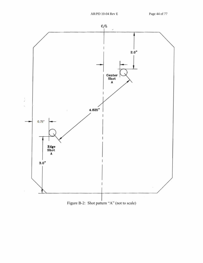
AR/PD 10-04 Rev E Page 44 of 77
Figure B-2: Shot pattern “A” (not to scale)
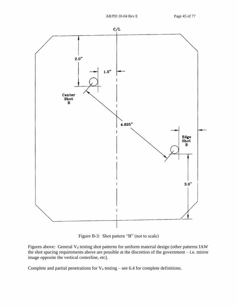
AR/PD 10-04 Rev E Page 45 of 77
Figure B-3: Shot pattern “B” (not to scale)
Figures above: General V0 testing shot patterns for uniform material design (other patterns IAW
the shot spacing requirements above are possible at the discretion of the government – i.e. mirror
image opposite the vertical centerline, etc).
Complete and partial penetrations for V0 testing – see 6.4 for complete definitions.

AR/PD 10-04 Rev E Page 46 of 77
APPENDIX C: NON-BALLISTIC REQUIREMENTS AND VERIFICATIONS

AR/PD 10-04 Rev E Page 47 of 77
Appendix Scope: The purpose of this appendix is to provide details on the non-ballistic
requirements and verifications. This Appendix is a mandatory part of the specification. The
information contained herein is intended for compliance.
Table I. Requirements and Verifications (see 4.5)
CHARACTERISTIC REQUIREMENT
PARAGRAPH
VERIFICATION
PARAGRAPH
FAT
For Initial
Production
LAT
Cloth Outer and Inner
Shell 3.2.1 4.5 X COC
Breaking Strength 3.2.1
ASTM D5034,
G-E or G-T X COC
Dimensional Stability 3.2.1
AATCC 96
Option 1C, A X COC
Outershell and
Innershell Cloth
Abrasion Resistance*
3.2.1 ASTM D 3884* X COC
Spray Rating:
Initial 1 Laundering 3.2.1 AATCC 22 &
4.5.11 X COC
Hydrostatic Resistance:
Initial
After 1 Laundering
After 1 Laundering and
POL Contamination
After 1 Laundering and
Insect Repellent
After 1 Laundering and
Sweat Contamination
After 1 Laundering and
Sea Water
Contamination
3.2.1 AATCC 127 &
4.5.10 X
COC
Dynamic Absorption:
After 1 Laundering 3.2.1
4.5.11 &
AATCC 70 X COC
Resistance to Organic
Liquids:
Initial
After 1 Laundering
3.2.1 4.5.11 &
AATCC 118 X COC
Flame Resistant 3.2.1.1
4.5.13 &
ASTM-D-6413 X COC***
Cloth Ballistic Panel
Cover. 3.2.2 4.3.1 X COC
Webbings and Tapes 3.2.3 4.3.1 X COC
Fasteners, Hook and 3.2.4 4.3.1 X COC

AR/PD 10-04 Rev E Page 48 of 77
CHARACTERISTIC REQUIREMENT
PARAGRAPH
VERIFICATION
PARAGRAPH
FAT
For Initial
Production
LAT
Loop
Foam 3.2.6 4.3.1 X COC
Polyethylene 3.2.5 4.3.1 X COC
Thread 3.2.8 4.3.1 X COC
“D”-Ring 3.2.9 4.3.1 X COC
Ladderloc 3.2.10 4.3.1 X COC
Webbing Hanger 3.2.11 4.3.1 X COC
Female Buckle Non-
Adj. 3.2.12 4.3.1 X COC
Female Buckle Adj. 3.2.13 4.3.1 X COC
Male Buckle Non-Adj. 3.2.14 4.3.1 X COC
Male Buckle Adj. 3.2.15 4.3.1 X COC
Emergency Release
Assembly 3.2.8 4.3.1 X COC
Design (as described on
DD-1222) 3.3 4.4 X Y/N
Patterns 3.3.1 4.4 X X
System Performance
Requirements 3.4 4.4
Functional Integration 3.4.1 4.4 X X
Fungus Resistance 3.4.2 4.5.8 X COC
Use & Care Instruction 3.4.3 4.4 X
Camouflage 3.4.4 4.1 X X
Infrared Reflectance 3.4.5, 3.2.3, 3.2.4 4.5.9 X COC
Matching** 3.4.6 4.5.12 X COC**
Colorfastness to: 3.4.8 4.1
Laundering: 3 Cycles 3.4.8
AATCC 61
OPTION IA X COC
Light
3.4.8
AATCC 16
OPTION 1 or 3
(Exposure shall be 40
hrs or 170 kilojoules)
X COC
Crocking
3.4.8 AATCC 8 X COC
Perspiration
3.4.8
AATCC 15; EXCEPT
BOTH ACID AND
ALKALINE TEST
SHALL BE
PERFORMED
X COC
Area of Coverage 3.5 4.5.3, 4.5.4, 4.5.5 X COC

AR/PD 10-04 Rev E Page 49 of 77
CHARACTERISTIC REQUIREMENT
PARAGRAPH
VERIFICATION
PARAGRAPH
FAT
For Initial
Production
LAT
Finished Weight 3.5 4.5.6 X X
Finished Dimensions 3.5 4.5.2, 4.5.3, 4.5.4 X COC
Areal Density 3.5.2.1.1 4.5.5, 4.5.6 X COC
Removable Ballistic
Panel Subcomponent 3.5.2.1 4.5.1 X X
Ballistic Filler 3.5.2.1.1 4.5.5 & 4.5.6 X X
Hook and Loop
Fastener 3.5.3.1 4.5.1 X X
Buttonholes 3.5.3.6 4.5.1 X X & COC
Drag Strap 3.5.3.7 4.8 X X
Emergency Release
Mechanism 3.5.3.8 4.5.1 & 4.9 X X
SAPI Pocket 3.7 4.4, 4.5.2 X
X (visual
only)
* H-18 abrasive wheel with 1000 gm load shall be used. A hole shall be defined as the wear
through of one (1) warp and one (1) filling yarn at the same location.
** Matching verification shall be performed at a government directed lab.
*** COC shall include test data.
Table II. END ITEM DEFECTS (see 4.5.1)
EXAMINE DEFECT CLASSIFICATION*
MAJOR MINOR
Cloth Any hole, cut, or tear. 101
Any abrasion marks, broken or missing yarns
or multiple floats 102
Any mend, darn or patch. 103
Needle Chews. 104
Webbing or Tape Any hole, cuts, tears, or smash. 105
Not firmly and tightly woven, edges frayed or
scalloped. 106
Multiple floats. 201
Abrasion mark, slub, or broken end or pick. 107
Ends not fused as required. 202
Cabling Any hole, cut or tear, incomplete securing of
sleeve, impairing function. 108
Fastener Tape Any hole, cut or tear, hooks flattened, broken
or missing, impairing function. 110
Seams and
Stitching:
Incorrect Style. 115
Open Seams ½ inch or less. 205

AR/PD 10-04 Rev E Page 50 of 77
EXAMINE DEFECT CLASSIFICATION*
MAJOR MINOR
More than ½ inch
NOTE: A seam shall be classified as an open
seam when one or more stitched joining a seam
are broken or when two or more consecutive
skipped or runoff stitches occur.
116
Raw Edges More than ½ inch when securely caught in
stitching.
NOTE: Raw edges not securely caught in
stitching shall be classified as open seams.
206
Seam & Stitch Type Wrong seam or stitch type. 117
Stitch Tension Tension loose, resulting in loose bobbin or top
thread. 207
Excessively tight, resulting in puckering of
material. 208
Bartacks Any bartack omitted. 118
Any bartack not as specified or not in specified
location. 209
Loose stitching, incomplete or broken. 210
Stitching Ends Not secured as specified. 211
Thread Breaks,
Skipped Stitches, or
Run-Offs.
Not over stitched as specified.
NOTE: Thread breaks or two or more
consecutive skipped or run-off stitches not over
stitched shall be classified as open seams.
212
Component &
Assembly
Any area of ballistic filler bunched (i.e. does
not lie flat) 119
Any component part omitted or not as
specified (unless otherwise classified herein) 120
Needle Chews. 121
Any mend, darn, patch, holes, splice or other
unauthorized repair. 122
Location Markings Printed marking more than 1/32 inch in width
or not covered by component part. 213
Label Missing, incorrect, illegible. 123
Use & Care
Pamphlet
Omitted, printing or figures illegible, any page
missing. 215
*The presence of a number designates either major or minor. The value of the number is for
internal inspection purposes only.

AR/PD 10-04 Rev E Page 51 of 77
Table III. END ITEM DIMENSIONAL EXAMINATION
EXAMINE DEFECT CLASSIFICATION*
Major Minor
Dimensional
(overall)
Smaller than nominal dimensions less
applicable minus tolerance indicated but not
smaller than nominal dimensions less twice the
applicable minus tolerance.
Larger than nominal dimensional and
applicable plus tolerance.
124 216
Component and
Location
Dimensions
Not within specified tolerance
217
Stitch Margin
or Gage
Not within specified tolerance 218
Box, Box-X
and stitching
Dimensions not within specified tolerance
219
Hardware Not spaced within specified tolerance 220
*The presence of a number designates either major or minor. The value of the number is for
internal inspection purposes only.

AR/PD 10-04 Rev E Page 52 of 77
Table IV. Visual Examination of ballistic Filler Size (see 4.5.4)
Examine Defect Classification*
Size of Individual
Ballistic Filler
Assembly
A) Smaller than cutting pattern: Major Minor
(1) 3/16 inch to 3/8 inch at any point around the
periphery 1/ 2/ 221
(2) More than 3/8 inch at any point around the
periphery 1/ 2/ 125
(3) 1/8 inch up to 3/16 inch around entire
periphery 2/ 222
(4) More than 3/16 inch around entire periphery
2/ 126
B) larger than cutting pattern by 3/8 inch or
more at any point 1/ 2/ 223
*The presence of a number designates either major or minor. The value of the number is for
internal inspection purposes only.
1/ to be scored when condition exits for a length of more than 2 inches or if condition exists in
several areas with an accumulated distance of 4 inches.
2/ the front filler or back filler individual components, as applicable shall be examined with the
applicable cutting pattern centered on the filler components.
PRODUCT VERIFICATION TESTING PROTOCOL: SPCS non-ballistic Product Verification
Testing shall be conducted in accordance with section 4 and Tables I to IV above.
Accept / Reject criteria:
(1) One or more major/minor defects constitutes FAT rejection
All major and minor defects must be corrected prior to DCMA shipment of test articles. If
defects are found, the armor samples shall be re-inspected and resubmitted to DCMA for another
random inspection. If the armor samples fail three consecutive inspections the articles will FAIL
FAT.
The government reserves the right to conduct all non-ballistic tests and reject on identification of
any single nonconformance.
FIRST ARTICLE TESTING PROTOCOL: SPCS non-ballistic First Article Testing shall be
conducted in accordance with section 4 and Tables I to IV above.
Accept / Reject criteria:
AR/PD 10-04 Rev E Page 53 of 77
(2) One or more major/minor defects constitutes FAT rejection
All major and minor defects must be corrected prior to DCMA shipment of test articles. If
defects are found, the armor samples shall be re-inspected and resubmitted to DCMA for another
random inspection. If the armor samples fail three consecutive inspections the articles will FAIL
FAT.
The Government reserves the right to conduct all non-ballistic tests and reject on identification of
any single nonconformance.
LOT ACCEPTANCE TESTING PROTOCOL: SPCS non-ballistic Lot Acceptance Testing shall
be conducted in accordance with section 4 and Tables I to IV above.
Accept / Reject criteria:
(1) One or more major defects constitutes LAT rejection
(2) A minor defect rate higher than allowed by Table I-A (found in Appendix D) using
Acceptance Quality Limit (AQL) of 4.0 constitutes LAT rejection.
All major and minor defects must be corrected prior to DCMA shipment of test articles. If
defects are found, the armor samples for that respective lot shall be re-inspected and resubmitted
to DCMA for another random. If the armor samples fail three consecutive inspections the
articles will FAIL LAT.
The government reserves the right to conduct all non-ballistic tests and reject on identification of
any single nonconformance.

AR/PD 10-04 Rev E Page 54 of 77
APPENDIX D: BALLISTIC PERFORMANCE VERIFICATION

AR/PD 10-04 Rev E Page 55 of 77
Appendix Scope: The purpose of this appendix is to provide details on the ballistic performance
verification. This Appendix is a mandatory part of the specification. The information contained
herein is intended for compliance.
Table I-A. Requirements and Verifications (see 4.5)
CHARACTERISTIC REQUIREMENT
PARAGRAPH
VERIFICATION
PARAGRAPH
LOT
ACCEPTANCE
TESTING
Ballistic Protection
Levels
3.5.1 4.1, 4.4, & 4.5 X
Ballistic Performance 3.5.2 4.5 X
Fragmentation
Protection
3.5.2.2
4.5
X
Handgun Protection 3.5.2.3 4.5 X
Small Arms Protection 3.5.2.4 4.5 X*
*System level Small Arms Protection is for Govt. reference only during FAT and LAT.

AR/PD 10-04 Rev E Page 56 of 77
TECHNICAL DATA PACKAGE: The contractor shall provide data that shows all the
components and materials used in the SPCS meet all stated requirements of the Technical Data
Package.
Prior to Product Verification Testing submittal, contractors shall provide a Technical Data
Package (TDP) for each SPCS design submitted to the Government consisting of but not limited
to the following items:
Design nomenclature
Material configuration
o Type of materials used
All raw materials and components
Raw materials and component suppliers
Include all related special storage requirements
Include all shelf life expiration periods
o Build sheet/Cut Patterns
o Dry layup (unsown sample)
Additionally, a SPCS standard (size medium) represented by the design shall be submitted to the
Government. The Government will treat all information provided as Proprietary Information and
deem it close hold with restricted access. This information is required by the Government in
order to baseline and maintains configuration management of each SPCS design submitted for
PVT. The contractor shall refrain from using proprietary materials in the design. However, if
the contractor does use proprietary materials, the contractor shall disclose all proprietary
materials to enable the government to maintain configuration control.
PRODUCT VERIFICATION: SPCS Product Verification testing shall be conducted in
accordance with paragraph 4.6 and Table I-A1 below.
Table I-A1. Product Verification Test Matrix (panels required)
TEST System Testing
Threat “e”
2700 +50/-0 ft/sec
Number of
Panels
ESAPI V0 4 XS, 4 SM, 4
MED, 4 LG, 4 XL,
4 2XL
4 XS, 4 SM, 4
MED, 4 LG, 4 XL,
4 2XL
ESBI V0 22 Pockets* 25 Pockets
*
*SPCS pockets are all one size. Pockets will be taken from full systems supplied during PVT.
Product verification testing is required prior to FAT submittal and must be tested at a
Government facility. In order to proceed into FAT, system level testing must pass the
requirements outlined in Table I-A1 and the requirements below. Ballistic packages that fail to
meet these requirements will not be allowed to proceed into FAT. Products submitted during
this phase of testing shall be the same materials, processes, procedures, equipment, and facilities
that will be used to create vests for FAT.

AR/PD 10-04 Rev E Page 57 of 77
Statistical Confidence in Test Results: Table I-A2 below represents the resistance to
penetration and back face deformation statistical analysis required for product verification testing
for both system level tests carrier and side plate pocket. For resistance to penetration, the lower
confidence level for the probability of no penetration P(nP) is the statistic of interest and the
result compared against a 90% probability of no penetration for first shot and a 70% probability
of no penetration for the second shot. For back-face deformation (BFD), the Upper Tolerance
Limit will be computed using back-face deformation as a continuous normal random variable
and the result compared against the requirement.
Table I-A2. Statistical Analysis Method (system level)
1st shot 2nd shot Resistance to Penetration
90% Prob. of No Penetration (P(nP)) , 90% Confidence
70% Prob. of No Penetration (P(nP)), 90% Confidence
Back Face Deformation (≤44.0mm)
90% Upper Tolerance Limit / 90% Confidence
80% Upper Tolerance Limit / 90% Confidence
Analysis Methodologies: For each valid test shot, the result is determined to have experienced
either a system complete penetration or a system partial penetration (no penetration of the
system). The numbers of complete penetrations and no penetrations are the basis for calculating
the 90% LCL for P(nP) via the exact Clopper-Pearson method1, with the numerical result
truncated by applying the “floor function” to two-decimal place precision. The LCL for P(nP) is
calculated for the 1st and 2
nd shots by combining plate sizes. For system level testing with an
ESAPI plate the LCL is calculated for both shots 1 and 2. For system level testing with an ESBI
plate the LCL is calculated for only shot 1. The LCL must meet or exceed the requirement
specified in Table II-A2. For example, if the 90% LCL for the P(nP) associated with a set of
second shot data from FAT were calculated to be 0.699987, the reported result would be 0.69
and the outcome would be considered to be non-compliant with the prescribed criterion of 0.70.
For back face deformation, the metric of merit is a one-sided Upper Tolerance Limit (UTL)
based on the assumption of normally distributed BFD data; the UTL to be calculated is specified
in Table II-A2. The BFD UTLs are calculated for the first and second shots by combining plate
sizes.
Validated one-decimal place BFD measurements, for tested hard armor inserts that did not
experience complete penetrations, are the basis for any UTL calculation. The UTL is defined as
Yu = Ῡ + ks, where Ῡ is the mean of all valid BFD measurements, k is a look-up constant2
(varying with the sample size, UTL percentage, and confidence percentage), and s is the sample
standard deviation. The UTL is reported to one decimal place precision after adjusting upwards
via the “ceiling function” – ensuring that a conservative UTL is reported. For example,
calculated results of 38.1349 mm and 38.1999 mm are each reported as 38.2 mm. Compliance
with the BFD requirement is achieved only if the associated UTL is less than or equal to
44.0mm.
When calculating the sample average (mean) and standard deviation in order to compute the
UTL, calculate both the mean and standard deviation to six significant digits. This is to avoid the

AR/PD 10-04 Rev E Page 58 of 77
rounding of these intermediate quantities affecting the reported UTL. The final result (the UTL)
is then reported to one decimal place as specified above.
The UTL is defined as Yu = Ῡ + ks, where Ῡ is the mean of all valid BFD measurements, k 1
Where
is the upper cutoff from an F distribution with v1 and v2 degrees of freedom. (Clopper
Pearson Formula from Casella, George and Roger Berger: Statistical Inference 2002 Duxbury / Thomson Learning
Inc, Pacific Grove, CA p 454.)
2 k=
where a=1-
- b=
-
= - b= - = -
and zutl is the critical value from the standard normal distribution associated with the UTL percentage. zconf is
the critical value from the standard normal distribution associated with the Confidence percentage and N is the total
sample size for the data of interest.
For PVT impact velocity anomalies, Table I-A3 identifies the standard fair/no test criteria for
this hard body armor standard. In the case of an under-velocity shot which results in either a
system complete penetration (CP) or a BFD greater than 44.0mm, the shot result will be included
in the analysis. If the under-velocity shot occurs on the first shot, the plate will be replaced with
a contingency plate to ensure a completed test matrix.
The Government will provide hard armor plate inserts (ESAPI/ESBI) that have had their design,
processes, and procedures certified during Government FAT and have also passed Government
LAT for the SPCS system tests.
Table I-A3. Fair Hit/No Test Criteria for Velocity Anomalies
Impact Velocity
Test Result Evaluator Accepts or Rejects for
Inclusion in Analysis Proceed to
next data point for that plate? Penetration BFD Penetration BFD
Acceptable No Penetration (PP and
CP) Measured
Include as success
Include Yes
Acceptable Complete System Penetration (CC)
Not measured Include as failure Not measured Yes
Too High No Penetration (PP and
CP) Measured Not included Not included No
Too High Complete System Penetration (CC)
Not Measured Not included Not included No
Too Low No Penetration (PP and
CP) Measured Not included
Not included if ≤ 44.0mm
Included if >
44.0mm
No
Too Low Complete System Penetration (CC)
Not measured Include as failure Not measured No

AR/PD 10-04 Rev E Page 59 of 77
FIRST ARTICLE TESTING PROTOCOL: SPCS First Article testing shall be conducted in
accordance with paragraph 4.6 and Table II-B1 below.
Table I-B1. First Article Test Matrix (panels required) TEST
3 17-grain FSP 9mm, 124 gr. FMJ
Remington
System Testing 1Threat “e”
2700 +50/-0 ft/sec
Number of Panels
V0 ~ 2 SM, 2 MD, 2 LG,
2 XL, 2 2XL
~ 2 SM, 2 MD, 2 LG,
2 XL, 2 2XL
V50, wet, 0° 2 LG 4 MD ~ 4 MD, 2 LG
V50, dry, 45° 2 XL ~ ~ 2 XL
V50, dry, 0° 2 SM
2 Cummerbund2
4 XL ~ 4 XL, 2 SM
2 Cummerbunds
V50, high T 2 XS ~ ~ 2 XS
V50, low T 2 MED ~ ~ 2 MED
V50,
Accelerated
Aging
2 XL ~ ~ 2 XL
V50, POL oil 2 LG ~ ~ 2 LG
V50, POL JP-8 1 SM, 1 LG ~ ~ 1 SM, 1 LG
ESAPI V0
(system level)
~ ~ 4 XS, 4 SM, 4
MED, 4 LG, 4 XL,
4 2XL
4 XS, 4 SM, 4
MED, 4 LG, 4XL,
4 2XL
ESBI V0
(system level)
~ ~ 22 Pockets4 22 Pockets
4
1System level testing is for Government Reference Only.
2Cummerbund V50 testing shall be conducted on multiple samples and can be varying in sizes.
All cummerbunds will be taken from the full systems supplied. 3Prior to conditioning, the heat sealed ballistic cover will be cut open carefully along the bottom
edge of the ballistic panel without cutting into the ballistic filler. 4SPCS pockets are all one size. Pockets and Cummerbunds will be taken from full systems.
The Contractor shall provide a total of 68 Complete End Items SPCS (all components must
be included) samples to the Government for First Article Testing as indicated below and a
minimum of two UID verification reports.
30 end item samples: First Article Testing (ballistic)
24 end item (4 each size) samples: First Article Testing (non-ballistic)
12 end item (2 each size) samples : FAT contingency / spares
1 end item sample Size M: Government record (DCMA)
1 end item sample Size M: Government record (PM SPE/TMD)
68 FAT SPCS Samples
Government samples will be retained as the manufacturing standard. Upon satisfactory
completion of FAT, all FAT samples will be returned to the Contractor – except Government
record vests.

AR/PD 10-04 Rev E Page 60 of 77
Statistical Confidence in Test Results: Table II-B2 below represents the resistance to
penetration and back face deformation statistical analysis for both system level tests carrier and
side plate pocket. For resistance to penetration, the lower confidence level for the probability of
no penetration P(nP) is the statistic of interest and the result compared against a 90% probability
of no penetration for first shot and a 70% probability of no penetration for the second shot. For
back-face deformation (BFD), the Upper Tolerance Limit will be computed using back-face
deformation as a continuous normal random variable and the result compared against the
requirement.
Table I-B2. Statistical Analysis Method
1st shot 2nd shot Resistance to Penetration
90% Prob. of No Penetration (P(nP)) , 90% Confidence
70% Prob. of No Penetration (P(nP)), 90% Confidence
*Back Face Deformation (≤44.0mm)
90% Upper Tolerance Limit / 90% Confidence
80% Upper Tolerance Limit / 90% Confidence
*90/90UTL for 9mm BFD will be across all shots taken.
Analysis Methodologies: For each valid test shot, the result is determined to have experienced
either a system complete penetration or a system partial penetration (no penetration of the
system). The numbers of complete penetrations and no penetrations are the basis for calculating
the 90% LCL for P(nP) via the exact Clopper-Pearson method1, with the numerical result
truncated by applying the “floor function” to two-decimal place precision. The LCL for P(nP) is
calculated for the 1st and 2
nd shots by combining shot locations, plate sizes, and environmental
conditions. The LCL must meet or exceed the requirement specified in Table 2. For example, if
the 90% LCL for the P(nP) associated with a set of second shot data from FAT were calculated
to be 0.699987, the reported result would be 0.69 and the outcome would be considered to be
non-compliant with the prescribed criterion of 0.70.
For back face deformation, the metric of merit is a one-sided Upper Tolerance Limit (UTL)
based on the assumption of normally distributed BFD data; the UTL to be calculated is specified
in Table II-B2. The BFD UTLs are calculated for the first and second shots by combining plate
sizes.
Validated one-decimal place BFD measurements, for tested hard armor inserts that did not
experience complete penetrations, are the basis for any UTL calculation. The UTL is defined as
Yu = Ῡ + ks, where Ῡ is the mean of all valid BFD measurements, k is a look-up constant2
(varying with the sample size, UTL percentage, and confidence percentage), and s is the sample
standard deviation. The UTL is reported to one decimal place precision after adjusting upwards
via the “ceiling function” – ensuring that a conservative UTL is reported. For example,
calculated results of 38.1349 mm and 38.1999 mm are each reported as 38.2 mm. Compliance
with the BFD requirement is achieved only if the associated UTL is less than or equal to
44.0mm.
When calculating the sample average (mean) and standard deviation in order to compute the
UTL, calculate both the mean and standard deviation to six significant digits. This is to avoid the

AR/PD 10-04 Rev E Page 61 of 77
rounding of these intermediate quantities affecting the reported UTL. The final result (the UTL)
is then reported to one decimal place as specified above.
The UTL is defined as Yu = Ῡ + ks, where Ῡ is the mean of all valid BFD measurements, k 1
Where
is the upper cutoff from an F distribution with v1 and v2 degrees of freedom. (Clopper
Pearson Formula from Casella, George and Roger Berger: Statistical Inference 2002 Duxbury / Thomson Learning
Inc, Pacific Grove, CA p 454.)
2 k=
where a=1-
- b=
-
= - b= - = -
and zutl is the critical value from the standard normal distribution associated with the UTL percentage. zconf is
the critical value from the standard normal distribution associated with the Confidence percentage and N is the total
sample size for the data of interest.
For impact velocity anomalies, Table II-B3 identifies the standard fair/no test criteria for this
hard body armor standard. In the case of an under-velocity shot which results in either a system
complete penetration (CP) or a BFD greater than 44.0mm, the shot result will be included in the
analysis. If the under-velocity shot occurs on the first shot, the plate will be replaced with a
contingency plate to ensure a completed test matrix.
Table I-B3. System Level Fair Hit/No Test Criteria for Velocity Anomalies
Impact Velocity
Test Result Evaluator Accepts or Rejects for
Inclusion in Analysis Proceed to next data
point? Penetration BFD Penetration BFD
Acceptable No Penetration (PP and
CP) Measured
Include as success
Include Yes
Acceptable Complete System Penetration (CC)
Not measured Include as failure Not measured Yes
Too High No Penetration (PP and
CP) Measured Not included Not included No
Too High Complete System Penetration (CC)
Not Measured Not included Not included No
Too Low No Penetration (PP and
CP) Measured Not included
Not included if ≤ 44.0mm
Included if >
44.0mm
No
Too Low Complete System Penetration (CC)
Not measured Include as failure Not measured No
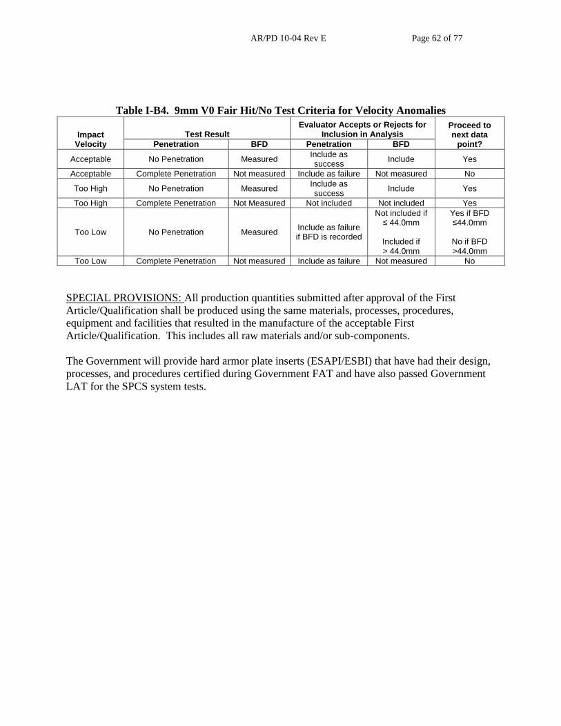
AR/PD 10-04 Rev E Page 62 of 77
Table I-B4. 9mm V0 Fair Hit/No Test Criteria for Velocity Anomalies
Impact Velocity
Test Result Evaluator Accepts or Rejects for
Inclusion in Analysis Proceed to next data
point? Penetration BFD Penetration BFD
Acceptable No Penetration Measured Include as success
Include Yes
Acceptable Complete Penetration Not measured Include as failure Not measured No
Too High No Penetration Measured Include as success
Include Yes
Too High Complete Penetration Not Measured Not included Not included Yes
Too Low No Penetration Measured Include as failure if BFD is recorded
Not included if ≤ 44.0mm
Included if > 44.0mm
Yes if BFD ≤44.0mm
No if BFD >44.0mm
Too Low Complete Penetration Not measured Include as failure Not measured No
SPECIAL PROVISIONS: All production quantities submitted after approval of the First
Article/Qualification shall be produced using the same materials, processes, procedures,
equipment and facilities that resulted in the manufacture of the acceptable First
Article/Qualification. This includes all raw materials and/or sub-components.
The Government will provide hard armor plate inserts (ESAPI/ESBI) that have had their design,
processes, and procedures certified during Government FAT and have also passed Government
LAT for the SPCS system tests.
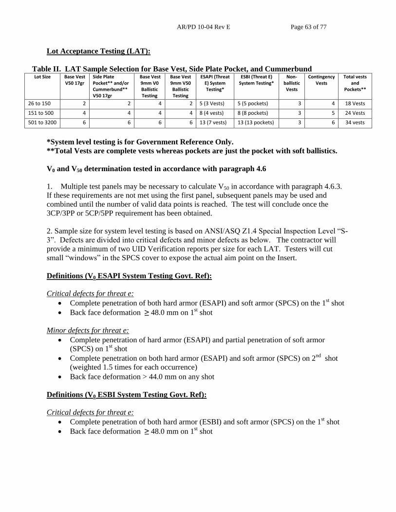
AR/PD 10-04 Rev E Page 63 of 77
Lot Acceptance Testing (LAT):
Table II. LAT Sample Selection for Base Vest, Side Plate Pocket, and Cummerbund Lot Size Base Vest
V50 17gr Side Plate Pocket** and/or Cummerbund**
V50 17gr
Base Vest 9mm V0 Ballistic Testing
Base Vest 9mm V50 Ballistic Testing
ESAPI (Threat E) System Testing*
ESBI (Threat E) System Testing*
Non-ballistic
Vests
Contingency Vests
Total vests and
Pockets**
26 to 150 2 2 4 2 5 (3 Vests) 5 (5 pockets) 3 4 18 Vests
151 to 500 4 4 4 4 8 (4 vests) 8 (8 pockets) 3 5 24 Vests
501 to 3200 6 6 6 6 13 (7 vests) 13 (13 pockets) 3 6 34 vests
*System level testing is for Government Reference Only.
**Total Vests are complete vests whereas pockets are just the pocket with soft ballistics.
V0 and V50 determination tested in accordance with paragraph 4.6
1. Multiple test panels may be necessary to calculate V50 in accordance with paragraph 4.6.3.
If these requirements are not met using the first panel, subsequent panels may be used and
combined until the number of valid data points is reached. The test will conclude once the
3CP/3PP or 5CP/5PP requirement has been obtained.
2. Sample size for system level testing is based on ANSI/ASQ Z1.4 Special Inspection Level “S-
3”. Defects are divided into critical defects and minor defects as below. The contractor will
provide a minimum of two UID Verification reports per size for each LAT. Testers will cut
small “windows” in the SPCS cover to expose the actual aim point on the Insert.
Definitions (V0 ESAPI System Testing Govt. Ref):
Critical defects for threat e:
Complete penetration of both hard armor (ESAPI) and soft armor (SPCS) on the 1st shot
Back face deformation ≥ 48.0 mm on 1st shot
Minor defects for threat e:
Complete penetration of hard armor (ESAPI) and partial penetration of soft armor
(SPCS) on 1st shot
Complete penetration on both hard armor (ESAPI) and soft armor (SPCS) on 2nd
shot
(weighted 1.5 times for each occurrence)
Back face deformation > 44.0 mm on any shot
Definitions (V0 ESBI System Testing Govt. Ref):
Critical defects for threat e:
Complete penetration of both hard armor (ESBI) and soft armor (SPCS) on the 1st shot
Back face deformation ≥ 48.0 mm on 1st shot

AR/PD 10-04 Rev E Page 64 of 77
Minor defects for threat e:
Complete penetration of hard armor (ESBI) and partial penetration of soft armor (SPCS)
on 1st shot
Back face deformation > 44.0 mm on any shot
Definitions (V0 9mm Testing):
Critical defects:
Complete penetration on any shot.
Back face deformation > 44.0 mm.
Any of the above defects will result in a FAT or LAT failure.
Definitions (V50 testing):
Table I-A4. Test Parameters and Requirements for V50 Ballistic Limit Testing
Parameter Description
Value Section Ref. in MIL-STD-662F
Velocity of 1st Shot Reference Velocity -
Velocity step until 1st Reversal
-30.5 m/s (-100 ft/s) if 1st shot Penetration
5.3.5
+30.5 m/s (+100 ft/s) if 1st shot Stop Exception to
5.3.5
Velocity step until 2nd Reversal
± 22.9 m/s (± 75 ft/s) depending on result of previous shot
5.3.5
Velocity step after 2nd Reversal
± 15.2 m/s (+ 50 ft/s) depending on result of previous shot
5.3.5
One or more V50 subtest that results in a V50 that is less than the requirement will constitute LAT
rejection.
SPECIAL PROVISIONS
1) Lot Failure: When a lot fails LAT and is subsequently rejected, that lot is rejected in total and
no component parts may be used in the production of any other lot. Further, any lot that is
withdrawn prior to completion of Additional Testing procedures as required by the Q/A Test
Protocol will be considered as rejected and subject to the above conditions and restrictions.
Additional Testing must be completed within 30 days of the initial LAT. All failed LAT’s will
require a Failure Analysis.
The Government will provide hard armor plate inserts (ESAPI/ESBI) that have had their design,
processes, and procedures certified during Government FAT and have also passed Government
LAT for the SPCS system tests.

AR/PD 10-04 Rev E Page 65 of 77
ANSI / ASQ Z1.4 - Acceptable Quality Limits
LAT

AR/PD 10-04 Rev E Page 66 of 77
ANSI / ASQ Z1.4 Inspection Levels - Sample Size Code Letters

AR/PD 10-04 Rev E Page 67 of 77
V0 System Test Contingency Matrix (LAT)
Shot 1
Velocity Over Over Over Fair Fair Fair Under Under Under
Result Critical Defect
Minor Defect
No Minor Defect
Critical Defect
Minor Defect
No Minor Defect
Critical Defect
Minor Defect
No Minor Defect
Shot 2
Over Minor Defect 1 1 1 2, 4 2, 6 2, 3 2, 4 2, 6 1
Over
No Minor Defect 1 1 1 2, 4 2, 4 2, 4 2, 4 2, 5 1
Fair Minor Defect 1 1 1 2, 4 2, 4 2, 4 2, 4 2, 5 1
Fair
No Minor Defect 1 1 1 2, 4 2, 4 2, 4 2, 4 2, 5 1
Under Minor Defect 1 1 1 2, 4 2, 5 2, 5 2, 4 2, 5 1
Under
No Minor Defect 1 1 1 2, 4 2, 5 2, 5 2, 4 2, 5 1

AR/PD 10-04 Rev E Page 68 of 77
LEGEND: 1. No second shot; re-test on new plate
2. Continue with second shot
3. Wait until end of testing and tally total points. If vendor fails, re-test. If vendor passes then no need to re-test.
4. Data valid
5. Shoot second plate and compare total penalty points with first plate. Pick plate with most minor defects or any critical defects.
6. Shoot second plate and add points. Only consider 1st shot minor defects on first plate, compare 1
st plate to 2
nd plate total minor defects and
pick plate with most minor defects or any critical defects.
NO TESTS: 1. If the “edge strip” is impacted by the incoming projectile (indicating a shot too close to the edge), the plate will be a “No test” (rationale –
the plate can only pass)
2. If the 2nd
shot is not within the specified shot spacing the plate will be a “No test” (rationale – the plate can only pass)
3. If the clay sticks to the shoot pack in the BFD location as the shoot pack is removed and the BFD result is above 44.0 mm, test shall be
considered a “No test”. Rationale: Resulting BFD would inadvertently result in a deeper reading due to clay removal from the surface. If
the testing is using statistical sampling of BFDs, all instances of clay sticking to the shoot pack and creating a deeper BFD should be noted
and if the plate design fails due to high BFD, these cases need to be retested.
NOTES:
1. If silicon spray is used, remove immediately afterwards (scrape off and dispose surface clay).

AR/PD 10-04 Rev E Page 69 of 77
APPENDIX E: CONTENTS OF LABELS, AND USE AND CARE INSTRUCTIONS

AR/PD 10-04 Rev E Page 70 of 77
Appendix Scope: The purpose of this appendix is to provide details on the following: contents
of labels and care and use instructions. This Appendix is a mandatory part of the specification.
The information contained herein is intended for compliance.

AR/PD 10-04 Rev E Page 71 of 77
SOLDIER PLATE CARRIER SYSTEM FRONT CARRIER – AR/PD 10-04E04E
SIZE: NSN:
THE SOLDIER PLATE CARRIER SYSTEM (SPCS) WITH ALL SOFT BALLISTIC PANELS INSTALLED PROVIDES PROTECTION FROM FRAGMENTATION & 9-mm. THIS VEST DOES NOT PROTECT AGAINST KNIVES OR SHARP OBJECTS. DO NOT MACHINE WASH OR DRY. FAILURE TO FOLLOW THESE INSTRUCTIONS WILL DAMAGE THE VEST’S PROTECTIVE CAPABILITY.
CLEANING INSTRUCTIONS 1. Remove dirt from outer surface with a cloth or soft bristle brush. 2. Remove all ballistic panels and the Enhanced Small Arms Protective Inserts (ESAPI) and Enhanced
Side Ballistic Inserts (ESBI) from the outer shell and the component carriers. Soft ballistic Panels are ONLY to be cleaned by removing loose dirt from the surface and wiping clean with a moistened cloth or a soft bristle brush. Avoid submerging the panels in water; DO NOT bleach! DO NOT machine wash! DO NOT dry clean! DO NOT apply solvents to the ballistic panels! If the ballistic panels become wet allow them to air dry flat away from heat sources and out of direct sunlight. If the ballistic panels become saturated with liquids such as bleaches, JP-8, petroleum, oils or lubricants, turn them in for replacement as soon as possible.
3. Hand wash the SPCS base vest and component outer shells only in cold water with soap or a very mild detergent. DO NOT USE CAUSTIC CLEANERS, CHLORINE BLEACH, YELLOW SOAP, CLEANING FLUIDS OR SOLVENTS, WHICH WILL DISCOLOR AND DETERIORATE THE ITEMS!
4. Rinse the outer shells very thoroughly in clean water to wash out the soap. 5. Air-dry indoors, or in the shade, AWAY FROM HEAT SOURCES. 6. DO NOT ATTEMPT TO DYE THE ITEM OR FIX DISCOLORATIONS.
TURN IN YOUR ITEM IF: 1. Frags or bullets have hit them. 2. The outer cover is torn or damaged beyond field repair. 3. The hook and loop cannot be closed completely or repaired. 4. The webbing is torn or damaged beyond repair. 5. The items cannot be adequately cleaned, or are badly discolored. 6. The items have open seams or broken components.
REFER TO USE & CARE MANUAL FOR THE PROPER USE OF THIS BALLISTIC PROTECTIVE SYSTEM, REPAIR PROCEDURES & RECORDING OF HITS. LOT NUMBER:_______________________________ DATE OF MFG:______________________________ SERIAL NO:__________________________________ CONTRACT #: MANUFACTURED BY:

AR/PD 10-04 Rev E Page 72 of 77
SOLDIER PLATE CARRIER SYSTEM BACK CARRIER – AR/PD 10-04E04E
SIZE: NSN:
THE SOLDIER PLATE CARRIER SYSTEM (SPCS) WITH ALL SOFT BALLISTIC PANELS INSTALLED PROVIDES PROTECTION FROM FRAGMENTATION & 9-mm. THIS VEST DOES NOT PROTECT AGAINST KNIVES OR SHARP OBJECTS. DO NOT MACHINE WASH OR DRY. FAILURE TO FOLLOW THESE INSTRUCTIONS WILL DAMAGE THE VEST’S PROTECTIVE CAPABILITY.
CLEANING INSTRUCTIONS 1. Remove dirt from outer surface with a cloth or soft bristle brush. 2. Remove all ballistic panels and the Enhanced Small Arms Protective Inserts (ESAPI) and Enhanced
Side Ballistic Inserts (ESBI) from the outer shell and the component carriers. Soft ballistic Panels are ONLY to be cleaned by removing loose dirt from the surface and wiping clean with a moistened cloth or a soft bristle brush. Avoid submerging the panels in water; DO NOT bleach! DO NOT machine wash! DO NOT dry clean! DO NOT apply solvents to the ballistic panels! If the ballistic panels become wet allow them to air dry flat away from heat sources and out of direct sunlight. If the ballistic panels become saturated with liquids such as bleaches, JP-8, petroleum, oils or lubricants, turn them in for replacement as soon as possible.
3. Hand wash the SPCS base vest and component outer shells only in cold water with soap or a very mild detergent. DO NOT USE CAUSTIC CLEANERS, CHLORINE BLEACH, YELLOW SOAP, CLEANING FLUIDS OR SOLVENTS, WHICH WILL DISCOLOR AND DETERIORATE THE ITEMS!
4. Rinse the outer shells very thoroughly in clean water to wash out the soap. 5. Air-dry indoors, or in the shade, AWAY FROM HEAT SOURCES. 6. DO NOT ATTEMPT TO DYE THE ITEM OR FIX DISCOLORATIONS.
TURN IN YOUR ITEM IF: 1. Frags or bullets have hit them. 2. The outer cover is torn or damaged beyond field repair. 3. The hook and loop cannot be closed completely or repaired. 4. The webbing is torn or damaged beyond repair. 5. The items cannot be adequately cleaned, or are badly discolored. 6. The items have open seams or broken components.
REFER TO USE & CARE MANUAL FOR THE PROPER USE OF THIS BALLISTIC PROTECTIVE SYSTEM, REPAIR PROCEDURES & RECORDING OF HITS. LOT NUMBER:_______________________________ DATE OF MFG:______________________________ SERIAL NO:__________________________________ CONTRACT #: MANUFACTURED BY:

AR/PD 10-04 Rev E Page 73 of 77
SOLDIER PLATE CARRIER SYSTEM – SIDE PANEL BALLISTIC INSERT– AR/PD 10-04E04E
SIZE: NSN:
INSERT THIS SIDE TO BODY FAILURE TO INSERT THIS BALLISTIC INSERT IN THE SPCS OUTERSHELL WILL RESULT IN ABSENCE OF BALLISTIC PERFORMANCE FROM FRAGMENTATION & 9-mm.
DO NOT LAUNDER BALLISTIC PANELS!
Avoid submerging in wash water. DO NOT bleach! DO NOT machine wash! DO NOT dry clean! DO NOT apply solvents! FOR CLEANING: ONLY Remove loose dirt from surface & wipe clean with a moistened cloth or soft bristle brush. If Ballistic Panels become wet allow to air dry in a flat position away from heat sources & out of direct sunlight. If Ballistic panels become saturated with liquids such as bleaches, JP-8, petroleum, oils, or lubricants, TURN IN FOR REPLACEMENT AS SOON AS POSSIBLE. LOT NUMBER:_______________________________ DATE OF MFG:______________________________ SERIAL NO:__________________________________ CONTRACT #: MANUFACTURED BY:
SOLDIER PLATE CARRIER SYSTEM – CUMMERBUND BALLISTIC INSERT– AR/PD 10-04E04E
SIZE: NSN:
INSERT THIS SIDE TO BODY FAILURE TO INSERT THIS BALLISTIC INSERT IN THE SPCS OUTERSHELL WILL RESULT IN ABSENCE OF BALLISTIC PERFORMANCE FROM FRAGMENTATION & 9-mm.
DO NOT LAUNDER BALLISTIC PANELS!
Avoid submerging in wash water. DO NOT bleach! DO NOT machine wash! DO NOT dry clean! DO NOT apply solvents! FOR CLEANING: ONLY Remove loose dirt from surface & wipe clean with a moistened cloth or soft bristle brush. If Ballistic Panels become wet allow to air dry in a flat position away from heat sources & out of direct sunlight. If Ballistic panels become saturated with liquids such as bleaches, JP-8, petroleum, oils, or lubricants, TURN IN FOR REPLACEMENT AS SOON AS POSSIBLE. LOT NUMBER:_______________________________ DATE OF MFG:______________________________ SERIAL NO:__________________________________ CONTRACT #: MANUFACTURED BY:

AR/PD 10-04 Rev E Page 74 of 77
SOLDIER PLATE CARRIER SYSTEM SIDE PLATE CARRIER – AR/PD 10-04E04E
SIZE: SIDE: NSN:
Refer to SPCS outershell label for cleaning and maintenance instructions. LOT NUMBER:____________________ DATE OF MFG:___________________ SERIAL NO:_____________________ CONTRACT #: MANUFACTURED BY:
SOLDIER PLATE CARRIER SYSTEM
CUMMERBUND SIDE PLATE POCKET – AR/PD 10-04E04E SIZE: NSN:
Refer to SPCS outershell label for cleaning and maintenance instructions. LOT NUMBER:____________________ DATE OF MFG:___________________ SERIAL NO:_____________________ CONTRACT #: MANUFACTURED BY:
SOLDIER PLATE CARRIER SYSTEM CUMMERBUND – AR/PD 10-04E04E
SIZE: SIDE: NSN:
Refer to SPCS outershell Label for cleaning and maintenance instructions. LOT NUMBER:______________________ DATE OF MFG:_____________________ SERIAL NO:_____________________ CONTRACT #: MANUFACTURED BY:
AR/PD 10-04 Rev E Page 75 of 77
APPENDIX F: CONTENTS OF LABELS, AND USE AND CARE INSTRUCTIONS FOR
FRONT AND BACK BALLISTICS

AR/PD 10-04 Rev E Page 76 of 77
Appendix Scope: The purpose of this appendix is to provide details on the following: contents
of labels and care and use instructions on the front and back ballistics. This Appendix is a
mandatory part of the specification. The information contained herein is intended for
compliance.
SOLDIER PLATE CARRIER SYSTEM - FRONT BALLISTIC INSERT– AR/PD 10-04E04E
SIZE: NSN:
INSERT THIS SIDE TO BODY FAILURE TO INSERT THIS BALLISTIC INSERT IN THE SPCS OUTERSHELL WILL RESULT IN ABSENCE OF BALLISTIC PERFORMANCE FROM FRAGMENTATION & 9-mm.
DO NOT LAUNDER BALLISTIC PANELS!
Avoid submerging in wash water. DO NOT bleach! DO NOT machine wash! DO NOT dry clean! DO NOT apply solvents! FOR CLEANING: ONLY Remove loose dirt from surface & wipe clean with a moistened cloth or soft bristle brush. If Ballistic Panels become wet allow to air dry in a flat position away from heat sources & out of direct sunlight. If Ballistic panels become saturated with liquids such as bleaches, JP-8, petroleum, oils, or lubricants, TURN IN FOR REPLACEMENT AS SOON AS POSSIBLE. LOT NUMBER:_______________________________ DATE OF MFG:______________________________ SERIAL NO:__________________________________ CONTRACT #: MANUFACTURED BY:
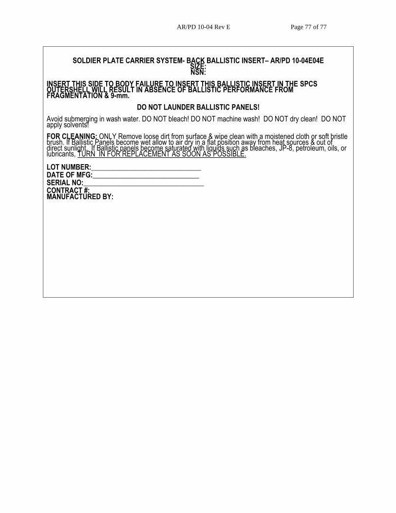
AR/PD 10-04 Rev E Page 77 of 77
SOLDIER PLATE CARRIER SYSTEM- BACK BALLISTIC INSERT– AR/PD 10-04E04E SIZE: NSN:
INSERT THIS SIDE TO BODY FAILURE TO INSERT THIS BALLISTIC INSERT IN THE SPCS OUTERSHELL WILL RESULT IN ABSENCE OF BALLISTIC PERFORMANCE FROM FRAGMENTATION & 9-mm.
DO NOT LAUNDER BALLISTIC PANELS!
Avoid submerging in wash water. DO NOT bleach! DO NOT machine wash! DO NOT dry clean! DO NOT apply solvents! FOR CLEANING: ONLY Remove loose dirt from surface & wipe clean with a moistened cloth or soft bristle brush. If Ballistic Panels become wet allow to air dry in a flat position away from heat sources & out of direct sunlight. If Ballistic panels become saturated with liquids such as bleaches, JP-8, petroleum, oils, or lubricants, TURN IN FOR REPLACEMENT AS SOON AS POSSIBLE. LOT NUMBER:_______________________________ DATE OF MFG:______________________________ SERIAL NO:__________________________________ CONTRACT #: MANUFACTURED BY: