army tm 11-6625-3213-14&p navy et900-ab-omp-010/ts …
TRANSCRIPT

ARMY TM 11-6625-3213-14&PNAVY ET900-AB-OMP-010/TS-4255-GRC 215
AIR FORCE TO 33D7-29-80-1
OPERATOR’S, UNIT,DIRECT SUPPORT AND GENERAL SUPPORT
MAINTENANCE MANUAL INCLUDINGREPAIR PARTS AND SPECIAL TOOLS LIST
TEST SET, MANPACKTS-4255/GRC-21 5
(NSN 6625-01-267-4402)
DEPARTMENTS OF THE ARMY, THE NAVY, AND THE AIR FORCE15 JUNE 1990

TM 11-6625-3213-14&P • ET900-AB-OMP-010/TS-4255-GRC215 • TO 33D7-29-80-1
This publication Is required for official use or for administrative or operational purposes only.Distribution Is limited to US Government Agencies. Other requests for this document must bereferred to Commander, US Army Communications-Electronics Command and FortMonmouth, ATTN: AMSEL-LC-ME-P. Fort Monmouth, NJ 07703-5000.
DESTRUCTION NOTICE-Destroy by any method that will prevent disclosure of contents orreconstruction of the document.

TM 11-6625-3213-14&P • ET900-AB-OMP-010/TS-4255-GRC215 • TO 33D7-29-80-1
A/(B Blank)

TM 11-6625-3213-14&PET900-AB-OMP-010/TS-4255-GRC-215
TO 33D7-29-87-1
Technical Manual DEPARTMENTS OF THE ARMY,No. 11-6625-3213-14&P THE NAVY, AND THE AIR FORCETechnical ManualNo. ET900-AB-OMP-010/TS-4255-GRC-215Technical OrderTO 33D7-29-87-1 Washington, DC, 15 June 1990
OPERATOR’S, UNIT, DIRECT SUPPORTAND GENERAL SUPPORT MAINTENANCE MANUAL
INCLUDING REPAIR PARTS AND SPECIAL TOOLS LIST
TEST SET, MANPACK TS-4255/GRC-215(NSN 6625-01-267-4402)
REPORTING ERRORS AND RECOMMENDING IMPROVEMENTS
You can help improve this manual. If you find any mistakes or if you know of a way to improvethe procedures, please let us know. Mail your letter, DA Form 2028 (Recommended Changesto Publications and Blank Forms), or DA-Form 2028-2 located in back of this manual direct to:Commander, US Army Communications-Electronics Command and Fort Monmouth, ATTN:AMSEL-LC-ME-PS, Fort Monmouth, New Jersey 07703-5000.
For Air Force, submit AFTO Form 22 (Technical Order System Publication ImprovementReport and Reply) in accordance with paragraph 6-5, Section VI, T.O. 00-5-1. Forward directto prime ALC/MST.
For Navy, mail comments to the Commander, Space and Naval Warfare Systems Command,ATTN: SPAWAR 8122, Washington, DC, 20363-5100.
In either case a reply will be furnished direct to you.
TABLE OF CONTENTS
Section Title Page
I. INTRODUCTION................................................................................................................................ 1-1II. FUNCTIONAL DESCRIPTION........................................................................................................... 2-1III. PREPARATION FOR USE................................................................................................................. 3-1IV. OPERATION ...................................................................................................................................... 4-1V. MAINTENANCE ................................................................................................................................. 5-1VI. PREPARATION FOR STORAGE OR SHIPMENT ............................................................................ 6-1A. REFERENCES................................................................................................................................... A-1B. MAINTENANCE ALLOCATION CHART............................................................................................ B-1C. REPAIR PARTS AND SPECIAL TOOLS LIST .................................................................................. C-1
GLOSSARY................................................................................................................................ Glossary-1
i

TM 11-6625-3213-14&P • ET900-AB-OMP-010/TS-4255-GRC215 • TO 33D7-29-80-1
LIST OF ILLUSTRATIONS
Figure Title Page
1-1 Manpack R/E Test Set ....................................................................................................................... 1-12-1 Manpack R/E Test Set Front Panel.................................................................................................... 2-22-2 Manpack R/E Test Set Front Panel.................................................................................................... 2-42-3 Manpack R/E Test Set Front Panel.................................................................................................... 2-62-4 Manpack R/E Test Set Front Panel.................................................................................................... 2-82-5 Block Diagram .................. ................................................................................................................ 2-115-1 Operational Test Setup ...................................................................................................................... 5-15-2 100 W Tune Start Pulse Setup........................................................................................................... 5-65-3 Load Test Setup ................................................................................................................................. 5-75-4 Initial Setup......................................................................................................................................... 5-95-5 Front Panel Removal/Replacement ................................................................................................... 5-25FO-1 Schematic Diagram, TS-4255/GRC-215.................................................................................... LocatedFO-2 Pin Assignments, Cable Assy .................................................................................................... in Back
W1, W67, and W68 ................................................................................................................ of Manual
LIST OF TABLES
Table Title Page
2-1 Manpack R/E Test Set Controlsand Indicators (8 pages) .............................................................................................................. 2-2
2-2 Manpack R/E Test Set Cable Assemblies ...................................................................................... 2-92-3 Frequency Serial Data Bit Sequence .............................................................................................. 2-102-4 Harmonic Filter Codes..................................................................................................................... 2-134-1 Initial Position of Controls (2 pages) ............................................................................................... 4-1
ii

TM 11-6625-3213-14&P • ET900-AB-OMP-010/TS-4255-GRC215 • TO 33D7-29-80-1
SECTION I.
INTRODUCTION
1-1. SCOPE.
This manual contains operation and maintenance instructions for the Manpack R/E Test Set TS-4255/GRC-215 asshown in Figure 1-1. The material includes operating instructions, functional descriptions, maintenance andtroubleshooting procedures, Repair Parts and Special Tools Lists, and instructions for preparation for use, storage andshipment.
Figure 1-1. Manpack R/E Test Set
1-2. MAINTENANCE FORMS, RECORDS, AND REPORTS
a. Reports of Maintenance and Unsatisfactory Equipment. Department of the Army forms and procedures used forequipment maintenance will be those prescribed by DA Pam 738-750, as contained in Maintenance Management Update.Air Force personnel will use AFR 66-1 for maintenance reporting and TO-00-35D54 for unsatisfactory equipment reporting.Navy personnel will report maintenance performed utilizing the Maintenance Data Collection Subsystem (MDCS) IAWOPNAVINST 4790.2, Vol 3 and unsatisfactory material/conditions (UR submissions) IAW OPNAVINST 4790.2, Vol 2,chapter 17.
1-1

TM 11-6625-3213-14&P • ET900-AB-OMP-010/TS-4255-GRC215 • TO 33D7-29-80-1
1-2. MAINTENANCE FORMS, RECORDS, AND REPORTS (Cont.)
b. Reporting of Item and Packaging Discrepancies. Fill out and forward SF 364 (Report of Discrepancy (ROD)) asprescribed in AR 735-11-2/DLAR 4140.55/SECNAVINST 4355.18/AFR 400-54/MCO 4430.3J.
c. Transportation Discrepancy Report (TDR) (SF 361). Fill out and forward Transportation Discrepancy Report (TDR)(SF 361) as prescribed in AR 55-38/NAVSUPINST 4610.33C/AFR 75-18/MCO P4610.19D/DLAR 4500.15.
1-3. REPORTING EQUIPMENT IMPROVEMENT RECOMMENDATIONS (EIR)
a. Army. If your Manpack R/E Test Set needs improvement, let us know. Send us an EIR. You, the user, are the onlyone who can tell us what you don’t like about your equipment. Let us know why you don’t like the design or performance.Put it on an SF 368 (Product Quality Deficiency Report). Mail it to: Commander, US Army Communications-ElectronicsCommand and Fort Monmouth, ATTN: AMSEL-PA-MA-D, Fort Monmouth, New Jersey 07703-5000. We’ll send you areply.
b. Navy. Navy personnel are encouraged to submit EIR’s through their local Beneficial Suggestion Program.
c. Air Force. Air Force personnel are encouraged to submit EIR’s in accordance with AFR 900-4.
1-4. DESTRUCTION OF MATERIEL TO PREVENT ENEMY USE
a. Army. The destruction of Army electronic materiel to prevent enemy use shall be in accordance with TM 750-244-2.
b. Navy. Navy Personnel comply with the local Command Material Destruction Plan.
c. Air Force. Air Force personnel comply with TM 750-244-2 or the local Emergency Destruction plan.
1-5. EQUIPMENT DATA
a. Electrical Characteristics
Power Source: +24 VDC 0.2 AmpsPower Output: +24 VDC
b. Physical Characteristics
Width: 17 in. Height: 10.25 in.Depth: 12 in. Weight: 20 lbs.
1-6. SPECIAL TOOLS, TMDE, AND SUPPORT EQUIPMENT
Special tools, TMDE, and support equipment are listed in the Maintenance Allocation Chart (MAC), Appendix B.
1-2

TM 11-6625-3213-14&P • ET900-AB-OMP-010/TS-4255-GRC215 • TO 33D7-29-80-1
SECTION II.FUNCTIONAL DESCRIPTION
2-1. GENERAL
This section contains a general description and purpose for the Manpack R/E Test Set TS-4255/GRC-215, listings ofcontrols, functional descriptions of major components and block diagrams.
2-2. DESCRIPTION
The Manpack R/E Test Set tests the Receiver-Transmitter RT-1511/GRC-215 output power and VSWR, BITE circuits,synthesizer tuning time, and remote control functions of frequency and transmission mode to verify operation. Front-panelswitches create test signals that simulate control and status signals from the 100-W power amplifier (PA) and externalantenna tuning unit (ATU), select the frequency and mode of operation, select active or bypass mode of operation of boththe ATU and PA, and control the power to the Unit Under Test (UUT). Front-panel test points allow monitoring of serialdata and clock reference signals while front-panel LEDs verify UUT operation by indicating BITE status, harmonic filterselection, as well as power to the UUT.
2-1

TM 11-6625-3213-14&P • ET900-AB-OMP-010/TS-4255-GRC215 • TO 33D7-29-80-1
2-3. CONTROLS AND INDICATORS
Figures 2-1 through 2-4 illustrate the locations of front panel controls. Table 2-1 lists the controls by callout numberand gives a description of each control.
Figure 2-1. Manpack R/E Test Set Front Panel
Table 2-1. Manpack R/E Test SetControls and Indicators (1 of 8)
Fig. andIndex No. Name Purpose
2-1 -1 J1 Connects +24.0 VDC from power supply to test set.
-2 (TP2) Chassis ground.
-3 (TP8) Freq. SD clock
-4 (TP7) Serial data output from microprocessor (Freq. SD).
-5 (TP6) 10 KHz clock from R/E.
-6 (TP5) Serial Fail Frame signal from R/E.
2-2

TM 11-6625-3213-14&P • ET900-AB-OMP-010/TS-4255-GRC215 • TO 33D7-29-80-1
2-3. CONTROLS AND INDICATORS (Cont.)
Table 2-1. Manpack R/E Test SetControls and Indicators (2 of 8)
Fig. andIndex No. Name Purpose
2-1 -7 (E3) Input for Audio TX to R/E.
-8 E19 Amplified audio from handset. (not used)
-9 (E2) Chassis ground.
-10 (E4) Audio RX output from R/E.
-11 (E5) Chassis ground.
-12 (R1) Volume control for Audio RX to headset.
-13 J3 Connects handset to test set. (not used)
-14 J4 Connects Voltage Controlled Oscillator (VCO) toR/E through pin A1C of J12 to simulate fastsynthesizer of Vehicular Adapter Assembly (77.0 to104.99 MHz).
-15 J5 Connects VCO to R/E through pin A2C of J12 tosimulate fast synthesizer of Vehicular AdapterAssembly (74.5 to 75.5 MHz).
-16 J6 Connects VCO to R/E through pin 27 of J12 tosimulate fast synthesizer of Vehicular AdapterAssembly (500 KHz).
-17 (S28) Selects internal or external Serial Data Frame toUUT.
-18 TP12 Input for external data clock.
-19 J12 Connects control and status signals between UUTand test set.
-20 J11 Connects control and status signals between UUTand test set.
-21 (S13) When set to FRAME the microprocessor is enabled tosend serial data continuously for test purposes.
-22 (S12) Grounds pin 3 of IC AlU15 to set the UUT in CWmode.
2-3
TM 11-6625-3213-14&P • ET900-AB-OMP-010/TS-4255-GRC215 • TO 33D7-29-80-1
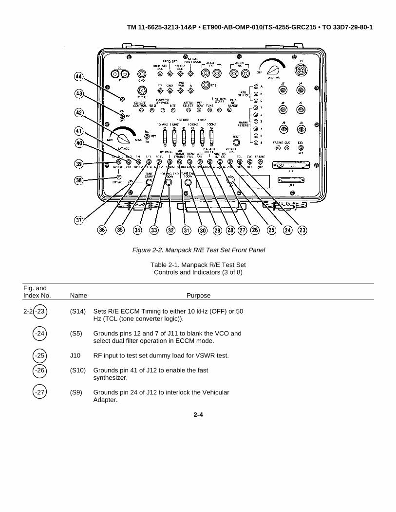
Figure 2-2. Manpack R/E Test Set Front Panel
Table 2-1. Manpack R/E Test SetControls and Indicators (3 of 8)
Fig. andIndex No. Name Purpose
2-2 -23 (S14) Sets R/E ECCM Timing to either 10 kHz (OFF) or 50Hz (TCL (tone converter logic)).
-24 (S5) Grounds pins 12 and 7 of J11 to blank the VCO andselect dual filter operation in ECCM mode.
-25 J10 RF input to test set dummy load for VSWR test.
-26 (S10) Grounds pin 41 of J12 to enable the fastsynthesizer.
-27 (S9) Grounds pin 24 of J12 to interlock the VehicularAdapter.
2-4

TM 11-6625-3213-14&P • ET900-AB-OMP-010/TS-4255-GRC215 • TO 33D7-29-80-1
2-3. CONTROLS AND INDICATORS (Cont.)
Table 2-1. Manpack R/E Test SetControls and Indicators (4 of 8)
Fig. andIndex No. Name Purpose
2-2 -28 (S8) Grounds pin 23 of J12 to simulates Fail signalfrom ATU to R/E.
-29 (S7) Connects +5 VDC to pin 3 of J12 to simulate Failsignal from PA .
-30 (S19) Momentary switch simulates end of tune phasesignal to R/E.
-31 (S2) Connects +5 VDC to pin 21 of J11 to enable theFrame Fail function.
-32 (S20) Momentary switch simulates end of homing phasesignal to R/E.
-33 (S1) Grounds pin 20 of J11 to place PA in bypass mode.
-34 (S3) Grounds pin 18 of J11 to connect RF signal toDummy Load through ATU.
-35 (S18) Momentary switch begins homing phase of ATU.
-36 (S4) Grounds pin 17 of J11 to select 25% output power.
-37 (DS1) Indicates homing phase of ATU in progress.
-38 (TP3) External AGC voltage.
-39 (S16) Grounds pin 15 of J11 to set R/E for external AGCand connects potentiometer R2 to pin 16 of J11.
-40 (S15) Selects upper or lower sideband (USB or LSB) modeof operation by R/E.
-41 (S6) Grounds pin 4 of J11 to set R/E for FrequencyHopping (FH) mode.
-42 (R2) Adjusts external Automatic Gain Control (AGC)voltage to R/E.
-43 (S11) Connects +24 VDC supply voltage to test set andUUT.
-44 (DS3) Indicates presence of +24 VDC from UUT to the testset.
2-5

TM 11-6625-3213-14&P • ET900-AB-OMP-010/TS-4255-GRC215 • TO 33D7-29-80-1
Figure 2-3. Manpack R/E Test Set Front Panel
Table 2-1. Manpack R/E Test SetControls and Indicators (5 of 8)
Fig. andIndex No. Name Purpose
2-3 -45 F1 6 amp fuse.
-46 (TP9) PTT signal.
-47 (TP1) Chassis ground.
-48 (TP4) Detected forward power level.
-49 (TP10) Test point for bit A of VSWR Reducer code.
-50 (DS6) Indicates the 6dB attenuator of the PA isinserted.
-51 (DS10) Indicates logic level of bit C of VSWR Reducercode.
2-6

TM 11-6625-3213-14&P • ET900-AB-OMP-010/TS-4255-GRC215 • TO 33D7-29-80-1
2-3. CONTROLS AND INDICATORS (Cont.)
Table 2-1. Manpack R/E Test SetControls and Indicators (6 of 8)
Fig. andIndex No. Name Purpose
2-3 -52 (DS9) Indicates logic level of bit B of VSWR Reducercode.
-53 (DS8) Indicates logic level of bit A of VSWR Reducercode.
-54 J7 Local oscillator input to synthesizer testcircuits. (not used)
-55 (DS15) Indicates Filter FL1 (2.0 to 2.99 MHz) of PAselected.
-56 J8 RF input to synthesizer test circuits from UUT.(not used)
-57 (DS16) Indicates Filter FL2 (3.0 to 4.99 MHz) of PAselected.
-58 J9 Output from synthesizer test circuits. (not used)
-59 (DS17) Indicates Filter FL3 (5.0 to 7.99 MHz) of PAselected.
-60 (DS18) Indicates Filter FL4 (8.0 to 11.99 MHz) of PAselected.
-61 (TP11) Input for external serial data frame.
-62 (DS19) Indicates Filter FL5 (12.0 to 18.99 MHz) of PAselected.
-63 (DS20) Indicates Filter FL6 (19.0 to 29.99 MHz) of PAselected.
-64 (S21) Momentary switch connects +5 VDC to JK flip-flopA1U17 causing a test of the R/E.
-65 (DS14) Indicates that selected frequency is out of rangefor R/E.
-66 (DS11) Indicates ATU, internal or external, is in the RFTune phase.
-67 (S27) Selects operating frequency of R/E in incrementsof 100 Hz.
2-7

TM 11-6625-3213-14&P • ET900-AB-OMP-010/TS-4255-GRC215 • TO 33D7-29-80-1
Figure 2-4. Manpack R/E Test Set Front Panel
Table 2-1. Manpack R/E Test SetControls and Indicators (7 of 8)
Fig. andIndex No. Name Purpose
2-4 -68 (DS13) Indicates ATU, internal or external, is in thehoming or tuning phase.
-69 (S26) Selects operating frequency of R/E in incrementsof 1 KHz.
-70 (S25) Selects operating frequency of R/E in incrementsof 10 KHz.
-71 (S24) Selects operating frequency of R/E in incrementsof 100 KHz.
-72 (S23) Selects operating frequency of R/E in incrementsof 1 MHz.
2-8

TM 11-6625-3213-14&P • ET900-AB-OMP-010/TS-4255-GRC215 • TO 33D7-29-80-1
2-3. CONTROLS AND INDICATORS (Cont.)
Table 2-1. Manpack R/E Test SetControls and Indicators (8 of 8)
Fig. andIndex No. Name Purpose
2-4 -73 (S22) Selects operating frequency of R/E in incrementsof 10 MHz.
-74 (S17) Grounds pin 23 of J11 to simulate PTT signal toUUT.
-75 (DS12) Indicates Push-To-Talk (PTT) signal to PA.
-76 (DS2) Indicates BITE status of R/E.
-77 (DS7) Indicates +24 VDC to the UUT.
-78 (DS4) Indicates the RF signal is routed to the 50 ohmdummy load by the ATU.
-79 (DS5) Indicates the PA is in bypass mode.
Table 2-2. Manpack R/E Test Set Cable Assemblies
Cable Part Number Title
W1 569712-801 DC Power Cable
W67 3-94310//B None
W68 3-94311//B None
2-4. FUNCTIONAL DESCRIPTION OF MANPACK R/E TEST SET
The Manpack R/E Test Set is powered by an external power supply providing +24.0 VDC operating voltage throughDC power cable W1 to connector J1. Switch S11l connects the voltage through fuse F1, a 6-amp fuse, to connector J12with pins 4, 28, and 29 supplying power to the UUT and the test set. A ground is applied to pin 33 of connector J12 to lightLED DS7, indicating the R/E is in a power-on condition. (See FO-1.) The +24.0 VDC connects back to the test set by theUUT through pin 3 of connector J11. The voltage connects through diode CR1 to LED DS3, which lights when switch S11closes. The +24.0 VDC also connects through diode CR1 to voltage regulator U1, which regulates the voltage to +5.0 VDCfor use by circuits on CCA A1.
2-9

TM 11-6625-3213-14&P • ET900-AB-OMP-010/TS-4255-GRC215 • TO 33D7-29-80-1
2-4. FUNCTIONAL DESCRIPTION OF MANPACK R/E TEST SET (Cont.)
R/E remote control is a function of the test set. The frequency and mode information is converted from parallel to serialdata so that it can be applied to the R/E. The CPU A1U4 receives its instruction set from the EPROM A1U5. It interfaceswith external circuitry through peripheral interface assemblies (PIA) A1U13 and A1U14. Upon power up,the reset circuit A1U1 and NAND gate A1U2 initialize the CPU. Frequency codes to be sent to the R/E are selected bydigit switches S22 through S27, each of which generate a 4-bit binary code to be stored in latches A1U6 through A1U11,respectively. The latches are enabled individually by IC A1U12, a Binary Code Decimal (BCD)-to-decimal converter thatdecodes the BCD address code generated by the PIA A1U13 at pins 14 through 17. The low enable signal causes theaddressed latch to place the 4-bit number onto the data bus to input pins 10 through 13 of A1U13. If the frequencyselected is out of range, a high logic-level signal at pin 9 of A1U13 is generated to forward-bias transistor A1Q3, effectivelyconnecting the cathode of LED DS14 to ground to indicate an out-of-range condition. A1U15 debounces the inputs ofswitches S12 (CW) and S15 (USB/LSB). It relays this MODE information to A1U14.
Another switch debounced by A1U15 is switch S14 (TCL). The function of switch S14 is to set the microprocessor in thesame state as the microprocessor located in the remote control set. Switch S13 (FRAME) is applied through A1U15 to pin6 of A1U14 to enable the serial data output of A1U14 for testing. The serial data is buffered by A1U16 and connects tofront-panel TP7 and pin 5 of connector J11. The serial data frame consists of six data frames, each made up of 48 bits.The data frames alternate between a valid frame and a nonvalid frame, the latter of which is composed of all 48 bits at ahigh logic level. The data frame may be verified using a data analyzer connected to TP7. The following table contains theserial data sequence generated by the microprocessor A1U14.
Table 2-3. Frequency Serial Data Bit Sequence
Bit Number Information Bit Number Information
1 Low 13 FL 52 Low 14 FL 63 High 15 LSB4 High 16 USB5 Low 17 through 41 Not used6 A 42 Test7 B 43 CW mode8 C 44 Low9 FL 1 45 High10 FL 2 46 High11 FL 3 47 Low12 FL 4 48 Low
2-10

TM 11-6625-3213-14&P • ET900-AB-OMP-010/TS-4255-GRC215 • TO 33D7-29-80-1
Figure 2-5. Block Diagram
The clock signal that drives the microprocessor is derived from a 4.0 MHz crystal Y1 and is divided down by A1U4 tothe clock reference frequency. The TCL reference clock signal is made available at TP8 and pin 2 of connector J11through the buffers of A1U16. The frequency will be either 10 kHz or 50 Hz, depending on whether switch S14 is to TCL orOFF. Switch S28, in the EXT position, allows connection of the external clock and data sources through TP11 and TP12so that an external data generator can drive the R/E.
2-11

TM 11-6625-3213-14&P • ET900-AB-OMP-010/TS-4255-GRC215 • TO 33D7-29-80-1
2-4. FUNCTIONAL DESCRIPTION OF MANPACK R/E TEST SET (Cont.)
A self-test of the R/E can be performed when switch S21 is pressed. This applies a leading edge to pin 3, the clockinput of A1U17, causing the output Q (pin 1) to go high. The high signal is applied to pin 7 of A1U14 to initiate the testsequence. The inverse Q output (pin 2) of the flip-flop goes low and holds the J input (pin 6) low so that the flip-flop will notrespond to switch S21 until it is reset. The K input (pin 5) is grounded preventing a second pulse to the clock input (pin 3)from resetting the flip-flop. At the end of the test phase, a reset signal is applied to pin 4 of the flip-flopby pin 19 of A1U14.
Audio test signals to the R/E can be applied by a handset connected to front panel connector J3. The audio isconnected through pin A and B to a 600-ohm matching impedance transformer T1, then to A2U3, an amplifier and audiocompressor that amplifies the audio level to about 100 mV. The signal is further amplified by the operational amplifierA2U2 and connected to the front panel by binding post E19. This signal connects by a jumper to the red binding post ofthe Audio TX connector and in turn to pin 24 of connector J11 at a level of 0 dBm (770 mV) into 600 ohms. The audiocompressor A2U3 and the operational amplifier are supplied +6 VDC by regulator A2U1. Variable resistor A2R8 providesoverall gain control for the op-amp. The PTT signal from the microtelephone connects from pin C of connector J3 to pin 23of connector J11 and to TP9 of the front panel. Switch S17 is used to simulate a PTT signal by grounding pin 23 ofconnector J11. LED DS12 indicates the PTT signal applied by the R/E to the PA when +5 VDC is connected to pin 15 ofconnector J12 by the R/E, and inverted by IC AlU18. Audio RX from the R/E is connected through pin 8 of connector J11to potentiometer R1, which is used to control the On/Off function as well as volume level to the external headset throughpin E of connector J3. The Audio RX signal also connects to front panel jack Audio RX (red).
A dummy load is built into the test set to allow measurement of the VSWR. The load is made up of four 50-ohm 150-watt resistors in parallel. This presents a load impedance of 12.5 ohms, a VSWR of 4:1, to the R/E which is connectedthrough front-panel connector J10.
The test set can simulate signals from an ATU, either internal to the R/E or external. The signals simulated are TuneStart, Homing End 100W, Tune End 100W, and ATU Fail. Momentary switch S18 begins the homing phase of the R/EATU or the external ATU by grounding pin 11 of connector J11. The R/E returns a ground signal to pin 11 of connector J11to signal the homing phase. This ground signal causes transistor Q2 to cut off, which in turn means that the +5 VDC isapplied to the base of transistor Q1, causing it to saturate. With transistor Q1 turned on the cathode of LED DS1 (TuneStart) connects to ground causing LED DS1 to light, indicating the ATU is in homing phase. Before the homing phase canbegin, however, switch S9 must be in the interlock position which grounds pin 24 of J12. This interlocks the operation ofthe R/E with the Vehicular Adapter. Switch S20 generates the Homing End signal by grounding pin 39 of connector J12,which is otherwise held at +5 VDC through pull-up
2-12

TM 11-6625-3213-14&P • ET900-AB-OMP-010/TS-4255-GRC215 • TO 33D7-29-80-1
2-4. FUNCTIONAL DESCRIPTION OF MANPACK R/E TEST SET (Cont.)
resistor R30. With PTT switch S17 set to TX, the tuning phase begins. The R/E returns a Fine Tune Start signal throughpin 40 of J12 to IC A1U19, which in turn connects a low logic signal to LED DS11, causing it to light. AlU19 acts as a bufferto Fine Tune Start and the ATU select codes from the R/E. The ATU select codes indicate which filter of the VSWRreducer is selected due to the setting of the frequency-code switches.
The code is connected to A1U19 through pins 5, 6, and 7 of connector J12 for bits A, B, and C, respectively. LEDsDS8, DS9, and DS10 are driven by A1U19 to display the codes as follows:
Table 2-4. Harmonic Filter Codes
Filter Frequency DS8 (A) DS9 (B) DS10 (C)Bandwidth (MHz)
1 2.0 to 2.499 1 0 02 2.5 to 3.499 0 1 03 3.5 to 4.99 1 1 04 5.0 to 7.499 0 0 15 7.5 to 13.99 1 0 16 14.0 to 30.0 0 0 0
A1U18 serves to interface the CMOS logic levels of the R/E with the TTL logic level of the test set. CMOS logic levelsignals include Tune, which indicates the overall tuning time (Homing and RF Tune), and PTT 100 W to pins 34 and 15 ofJ12, respectively. The Tune condition is indicated by LED DS13. The end of the overall tune phase signal is simulated bymomentary switch S19 (Tune End 100 W) which connects a +5 VDC pulse of at least 100 mSec duration to the R/Ethrough pin 39 of connector J12. Switch S8 simulates the ATU Fail signal by grounding pin 23 of connector J12 and switchS3 grounds pin 18 of J11, normally held high by pull-up resistor A1R3, to bypass the ATU and apply the RF signal to thedummy load. In bypass mode, the R/E returns a ground signal to pin 18 of connector J12, causing LED DS4 (50 ohms) tolight.
Connectors J4, J5, and J6 connect the Fast Synthesizer of the Vehicular Adapter to the R/E for use in ElectronicCounter-Counter Measures (ECCM) Mode. Connector J4 is the input for the 77-to-104.99 MHz signal of the VCO andconnects to pin A1C of J12 through a shielded cable. Connector J5 connects 74.5/75.5 MHz to pin A2C of connector J12,and J6 connects 500 KHz to pin 27 of connector J12. In ECCM mode, using the fast synthesizer requires using dualintermediate frequency (IF) filters alternately. Switch S5 grounds pins 7 and 12 of connector J11 to set the R/E to VCOBlank; this provides 40 dB of attenuation and sets the R/E for dual filter operation. Switch S10 applies ground to the fastsynthesizer
2-13

TM 11-6625-3213-14&P • ET900-AB-OMP-010/TS-4255-GRC215 • TO 33D7-29-80-1
2-4. FUNCTIONAL DESCRIPTION OF MANPACK R/E TEST SET (Cont.)
interlock signal line by grounding pin 41 of connector J12. Switch S6 grounds pin 4 of connector J11 to enable the audiocompressor of the R/E.
The R/E Test Set also functions to simulate the presence of the 100-W PA. Switch S1 simulates the bypass conditionof the PA by grounding pin 20 of connector J11. The R/E returns a CMOS level signal to pin 8 of connector J12. Thissignal is buffered by A2U4 which acts as a CMOS to TTL interface. The signal then connects to buffer A2U5, which drivesLED DS5 (100 W PA By-Pass). LEDs DS15 through DS20 indicate which of the 6 harmonic filters is inserted in the PA asa response to the frequency-code setting. A ground signal from the R/E connects to the cathode of the appropriate LEDthrough one of pins 9 through 14 of connector J12. Switch S4 grounds pin 17 of connector J11 to simulate control from theECCM module to select 25% operating power by the PA. LED DS6 indicates insertion of the 6dB attenuator in the PA,reducing power to 25 W. The signal from the R/E connects to pin 17 of connector J12 and then converts from CMOS to aTTL level signal by A2U4 and the LED driven by A2U5. Switch S7 simulates the 100-W PA Fail signal to the R/E byapplying +5 VDC to pin 3 of J12.
Other signals from the R/E that may be monitored at the front panel include the detected forward power level, which isconnected to pin 19 of connector J11 and brought up on TP4. The Serial Fail Frame connects to TP5 via pin 14 ofconnector J11. The 10 KHz clock signal, used for synchronization of the ECCM module, is connected to TP6 throughresistor A1R2 from pin 6 of J11. LED DS2 indicates the BITE condition of the R/E with +5 VDC applied to pin 9 of J11 fromthe R/E.
Switch S2 connects +5 VDC to pin 21 of connector J11 sending a Frame Fail Enable signal to the Bite module of theR/E. Switch S16, when set to EXT. AGC, connects potentiometer R2 to pin 16 of connector J11 and connects a ground topin 15 of connector J1 to set the R/E for external AGC. R2 is used to set the level of gain by the R/E by setting the AGCvoltage between 0 and +5 VDC. The EXT. AGC voltage also connects to TP3 of the test set for measurement. CircuitCard Assembly A3 is not used for maintenance or testing of the Regency Net system.
2-14
TM 11-6625-3213-14&P • ET900-AB-OMP-010/TS-4255-GRC215 • TO 33D7-29-80-1
SECTION III.
PREPARATION FOR USE
3-1. GENERAL
This section contains instructions for preparation for use of Manpack R/E Test Set TS-4255/GRC-215. These includeinstructions for unpacking, if any special procedures are required, inspecting unpacked equipment for damage, and anypreliminary servicing procedures required to prepare the equipment for operation.
3-2. UNPACKING
No special procedures are required for removing the test set from its shipping container. Use normal care in handlingelectronic equipment. Avoid jarring test set during removal.
3-3. CHECKING UNPACKED EQUIPMENT
a. Reporting of Item and Packaging Discrepancies. Fill out and forward SF 364 (Report of Discrepancy (ROD)) asprescribed in AR 735-11-2/DLAR 4140.55/SECNAVINST 4355.18/AFR 400-54/MCO 4430.3J.
b. Transportation Discrepancy Report (TDR) (SF 361). Fill out and forward Transportation Discrepancy Report (TDR)(SF 361) as prescribed in AR 55-38/NAVSUPINST 4610.33C/AFR 75-18/MCO P4610.19D/DLAR 4500.15.
c. Refer to DA Pam 25-30 to see if your equipment has had any Modification Work Orders (MWO) applied.
3-4. PRELIMINARY SERVICING OF EQUIPMENT
Prior to placing the test set in service, perform the following visual inspection procedures. Do not connect unit toprimary power source or any other equipment during these procedures.
a. Check all front panel connectors for broken, bent or missing pins.
b. Check all front panel mounted switches, lamps, or other hardware for damage.
3-1/(3-2 Blank)

TM 11-6625-3213-14&P • ET900-AB-OMP-010/TS-4255-GRC215 • TO 33D7-29-80-1
SECTION IV.
OPERATION
4-1. GENERAL
This section contains operating procedures for the Manpack R/E Test Set TS-4255/GRC-215.
4-2. INITIAL POSITION OF CONTROLS
Table 4-1 lists the initial positions of the front-panel controls prior to operating the equipment. See Figures 2-1 through2-4 for location of front-panel controls.
Table 4-1. Initial Position of Controls
Fig. andIndex No. Control Name Position
2-1-17 (S28) EXT/IN INT.
- 21 (S13) Frame OFF
- 22 (S12) CW OFF
2-2-23 (S14) TCL OFF
- 24 (S5) VCOBLK DFS OFF
- 26 (S10) SINT HS INT. CK. NORM
- 27 (S9) PA ATU INT. CK. NORM
- 28 (S8) ATU Fail NORM
- 29 (S7) 100W Fail NORM
- 31 (S2) Fail Frame Enable NORM
- 33 (S1) Bypass/Norm NORM
- 34 (S3) 50 ohm/Norm NORM
- 36 (S4) 1/1 1/4 1/1
- 39 (S16) EXT. AGC NORM
- 40 (S15) USB/LSB LSB
4-1

TM 11-6625-3213-14&P • ET900-AB-OMP-010/TS-4255-GRC215 • TO 33D7-29-80-1
4-2. INITIAL POSITION OF CONTROLS (Cont.)
Table 4-1. Initial Position of Controls (Cont.)
Fig. andIndex No. Control Name Position
2-2 - 41 (S6) FH NORM
- 43 (S11) ON/OFF DC OFF
2-4 - 74 (S17) PTT TX
4-3. OPERATING INSTRUCTIONS
Position the initial control settings as shown in Table 4-1. The test set lid stores the cable assemblies. Connect cableW1 to connector J1 on the test fixture and connect to the PP-8202/G power supply, adjust the power supply to +24.0(+23.0 to +25.0) VDC. Follow the test procedures in the technical manual for the UUT. When the test procedures arecompleted, switch S11 to OFF, and return all other switches to their initial positions.
4-2
TM 11-6625-3213-14&P • ET900-AB-OMP-010/TS-4255-GRC215 • TO 33D7-29-80-1
SECTION V.
MAINTENANCE
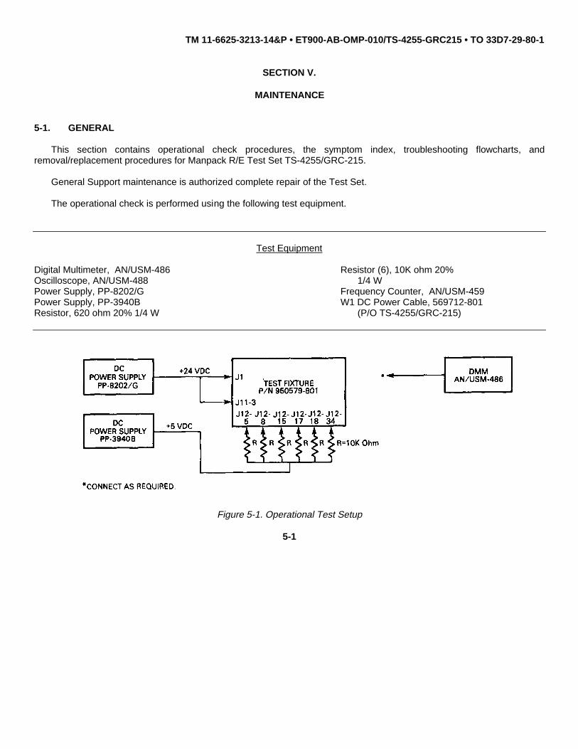
5-1. GENERAL
This section contains operational check procedures, the symptom index, troubleshooting flowcharts, andremoval/replacement procedures for Manpack R/E Test Set TS-4255/GRC-215.
General Support maintenance is authorized complete repair of the Test Set.
The operational check is performed using the following test equipment.
Test Equipment
Digital Multimeter, AN/USM-486 Resistor (6), 10K ohm 20%Oscilloscope, AN/USM-488 1/4 WPower Supply, PP-8202/G Frequency Counter, AN/USM-459Power Supply, PP-3940B W1 DC Power Cable, 569712-801Resistor, 620 ohm 20% 1/4 W (P/O TS-4255/GRC-215)
Figure 5-1. Operational Test Setup
5-1

TM 11-6625-3213-14&P • ET900-AB-OMP-010/TS-4255-GRC215 • TO 33D7-29-80-1
5-2. OPERATIONAL CHECK OF MANPACK R/E TEST SET
a. Continuity and Resistance Check
1. Disconnect power cable W1 from J1 and the PP-3940B from the 6 10-Kohm resistors. Measure for continuity (less than 1.5 ohms of resistance) between the following points:
FROM TO
J11 pin 8 RX Audio Red (E4)J11 pin 23 J3 pin CJ11 pin 23 TP9 (PTT)J11 pin 19 TP4 (Forward Power)J11 pin 24 TX Audio Red (E3)J11 pin 14 TP5 (Serial Fail Frame)J11 pin 12 J11 pin 7J11 pin 1 GNDJ11 pin 25 GNDJ12 pin 30 J12 pin 16J12 pins 1, 26, and 31 GNDRX Audio-Black GNDChassis Ground GNDTP2 (GND) TP1 (GND)TX Audio-Black GNDJ12 pin 4 J12 pins 28 and 29J4 conductor J12 pin A1conductorJ5 conductor J12 pin A2 conductorJ6 conductor J12 pin 27J12 pin Al shield GNDJ12 pin A2 shield GNDJ1-Black GNDJ3 pin D GND
2. Set switches as listed below and measure for continuity (less than 1.5 ohms) or an open circuit (more than 20 Mohms) between the following points:
SET-UP FROM TO CONDITION
PTT (S17) to TX J11 pin 23 J11 pin 25 continuityPTT (S17) to RX J11 pin 23 J11 pin 25 open circuitEXT AGC (S16) J11 pin 16 TP3 (EXT continuity to AGC AGC)EXT AGC (S16) J11 pin 16 TP3 (EXT open circuit to NORM AGC)VCO BLK (S5) J11 pin 12 GND continuity to VCO DFSVCO BLK (S5) to OFF J11 pin 12 GND open circuitFH (S6) to FH J11 pin 4 GND continuityFH (S6) to NORM J11 pin 4 GND open circuitPA ATU INT CK (S9) J12 pin 24 GND continuity to ATUPA ATU INT CK (S9) J12 pin 24 GND open circuit to NORM
5-2

TM 11-6625-3213-14&P • ET900-AB-OMP-010/TS-4255-GRC215 • TO 33D7-29-80-1
5-2. OPERATIONAL CHECK OF MANPACK R/E TEST SET (Cont.)
SET-UP FROM TO CONDITION
ATU Fail (S8) J12 pin 23 GND continuity to FAILATU Fail (S8) J12 pin 23 GND open circuit to NORMSINT HS (S10) J12 pin 41 GND continuity to SINTSINT HS (S10) J12 pin 41 GND open circuit to NORM
3. Set switches as listed below and measure for continuity (less than 1.5 ohms) or an open circuit (more than 20 Mohms) between the following points:
SET-UP FROM TO CONDITION
Bypass (S1) J11 pin 20 GND continuity to BYPASS50 OHM (S3) to J11 pin 18 GND continuity 50 OHM1/1 and 1/4 (S4) J11 pin 17 GND continuity to 1/4Tune Start (S18) J11 pin 11 GND continuity pressedEXT/INT (S28) J11 pin 2 TP11 (Frame) continuity to EXTEXT/INT (S28) J11 pin 5 TP12 (CLK) continuity to EXTEXT/INT (S28) J11 pin 2 TP11 (Frame) open circuit to INTEXT/INT (S28) J11 pin 5 TP12 (CLK) open circuit to INT
4. Switch 100W Fail (S7) to NORM and measure for the listed resistance values between the following points:
FROM TO RESISTANCE
J12 pin 3 GND 10.0 (9.5 to 10.5) KohmsJ12 pin 39 GND 100.0 (95.0 to 105.0) KohmsJ11 pin 6 10 kHz CLK 3.0 (2.85 to 3.15) Kohms
(TP6)J10 conductor GND 12.5 (11.2 to 13.8) ohms
5. Turn the volume control R1 counter-clockwise to OFF and verify an open circuit between J11 pin 8 and J3 pinE. Slowly rotate the control clockwise and verify that the resistance decreases from 4.7 Kohms to less than 10 ohms.
5-3

TM 11-6625-3213-14&P • ET900-AB-OMP-010/TS-4255-GRC215 • TO 33D7-29-80-1
5-2. OPERATIONAL CHECK OF MANPACK R/E TEST SET (Cont.)
b. Functional Checks
1. Reconnect the test set as shown in Figure 5-1 and adjust the PP-8202/G power supply to +24.0 (+23.0 to+25.0) VDC. Observe that DS3 is lit. Verify that switch S11 (ON/OFF) is set to OFF and measure betweenJ12 pin 4 and GND for less than +0.2 VDC.
2. Set switch S11 to ON and verify that LEDs DC ON (DS3), PTT 100W (DS12) and Tune (DS13) light while 50OHM (DS4), 100W PA Bypass (DS5), and Atten. Select (DS6) remain off.
3. Set the following switches to the positions listed and verify the voltages by measuring between GND and thefollowing points:
SET-UP Test Point VOLTAGE
Bypass/NORM (S1) J11 pin 20 +5.0 (+4.75 to +5.25) VDC to NORMBypass/NORM (S1) J11 pin 20 less than +0.2 VDC to BypassFail Frame Enable J11 pin 21 +5.0 (+4.75 to +5.25) VDC (S2) to ENABLEFail Frame Enable J11 pin 21 less than +0.2 VDC (S2) to NORM50 OHM/NORM (S3) J11 pin 18 +5.0 (+4.75 to +5.25) VDC to NORM50 OHM/NORM (S3) J11 pin 18 less than +0.2 VDC to 50 D
4. Set the following switches to the positions listed and verify the voltages by measuring between GND and thefollowing points:
SET-UP Test Point VOLTAGE
1/1 1/4 (S4) J11 pin 17 +5.0 (+4.75 to +5.25) VDC to 1/11/1 1/4 (S4) J11 pin 17 less than +0.2 VDC to 1/4EXT AGC (S16) J11 pin 15 +2.5 (2.0 to 3.0) VDC to NORMEXT AGC (S16) J11 pin 15 less than +0.2 VDC to AGC100W Fail (S7) J12 pin 3 +5.0 (+4.75 to +5.25) VDC to FAIL100W Fail (S7) J12 pin 3 less than +0.2 VDC to NORMTune End (S19) J12 pin 38 +5.0 (+4.75 to +5.25) VDC pressedNone J12 pin 38 less than +0.2 VDC
5-4

TM 11-6625-3213-14&P • ET900-AB-OMP-010/TS-4255-GRC215 • TO 33D7-29-80-1
5-2. OPERATIONAL CHECK OF MANPACK R/E TEST SET (Cont.)
SET-UP Test Point VOLTAGE
Homing End (S20) J12 pin 39 +5.0 (+4.75 to +5.25) VDC pressedNone J12 pin 39 less than +0.2 VDC
5. Measure for less than +0.2 VDC between A (TP10) and GND. Ground J12 pin 5 and measure +3.5 to 4.95VDC between TP10 and GND.
6. Set switch EXT AGC (S16) to EXT AGC. Slowly rotate EXT AGC (R2) clockwise, and verify that the voltageincreases from less than +0.2 VDC to +5.0 (+4.75 to +5.25) VDC at EXT AGC test point (TP3).
7. Ground the following connector pins and observe that the following LEDs light.
SET-UP LED
J12 pin 5 grounded LED ATU Select A (DS8)J12 pin 6 grounded LED ATU Select B (DS9)J12 pin 7 grounded LED ATU Select C (DS10)J12 pin 8 grounded LED 100-W PA Bypass (DS5)J12 pin 9 grounded LED Harm. FL1 (DS15)J12 pin 10 grounded LED Harm. FL2 (DS16)J12 pin 11 grounded LED Harm. FL3 (DS17)J12 pin 12 grounded LED Harm. FL4 (DS18)J12 pin 13 grounded LED Harm. FL5 (DS19)J12 pin 14 grounded LED Harm. FL6 (DS20)J12 pin 17 grounded LED Atten. Select (DS6)J12 pin 18 grounded LED 50 Ohm (DS4)J12 pin 33 grounded LED ON/OFF (DS7)J12 pin 40 grounded LED Fine Tune Start (DS11)
8. Ground pins 15 and 34 of J12 and observe that LEDs PTT (DS12) and Tune (DS13) respectively extinguish.
9. Press Tune Start switch (S18) and verify that LED DS1 (EXT AGC) lights.
5-5

TM 11-6625-3213-14&P • ET900-AB-OMP-010/TS-4255-GRC215 • TO 33D7-29-80-1
5-2. OPERATIONAL CHECK OF MANPACK R/E TEST SET (Cont.)
c. Test of Data Generation
1. Connect the Test Set as shown below in Figure 5-2. Adjust the PP-8202/G power supply for +24.0 (+23.0 to+25.0) VDC and set switch USB/LSB (S15) to LSB, CW (S12) and FRAME (S13) to OFF, TCL (S14) to TCLSet the frequency control to 18.2507 mHz.
Figure 5-2. 100 W Tune Start Pulse Test Setup
2. Set DC (S11) to ON, using oscilloscope connect one channel to FRAME FREQ. S.D. (TP7) and the otherchannel to FRAME S.D. CLK (TP8). Verify on TP7 a continuous data frame of about 2 seconds and on TP8 aclock signal of 50 (45 to 55) Hz. Set FRAME (S13) to ON and verify the FRAME and clock pulse duration of 6seconds (5 to 7) at every change of switches relevant to frequency and/or mode selection.
3. Return switches FRAME (S13) and TCL (S14) to OFF, EXT/INT (S28) to INT. Connect the oscilloscope topins 2 and 5 of J11 and verify the presence of the Serial Frame and Clock signals. Switch EXT/INT (S28) toEXT. and verify that the Serial Frame and Clock signals are no longer present.
4. Connect the scope probe to FREQ S.D. CLK (TP8) and verify the presence of the Serial Data Frame.
5. Set the frequency switches for 1.9999 MHz and observe that Out of Range LED (DS14) lights. Set thefrequency for 18.0000 MHz and observe that Out of Range LED (DS14) extinguishes.
6. Adjust the PP-3940B power supply to +2.0 (+1.75 to 2.25) VDC. Connect the positive lead to J11 pin 9 andthe negative lead to GND and verify that BITE LED (DS2) lights.
5-6

TM 11-6625-3213-14&P • ET900-AB-OMP-010/TS-4255-GRC215 • TO 33D7-29-80-1
5-2. OPERATIONAL CHECK OF MANPACK R/E TEST SET (Cont.)
d. Test of Dummy Load.
1. Disconnect all power to set. Connect DMM to the test set J10 and GND.
DIGITAL J10 TEST FIXTUREMULTIMETER P/N 950579-801AN/USM-486 GND
Figure 5-3. Load Test Setup
2. The resistance should be 12.5 ohms (11.875 to 13.125).
e. Continuity Testing of Associated Cables.
1. Test continuity of each cable (UUT), W1, W67, and W68 for less than 0.5 ohms resistance with DMM.
5-7

TM 11-6625-3213-14&P • ET900-AB-OMP-010/TS-4255-GRC215 • TO 33D7-29-80-1
5-3. SYMPTOM INDEX
The following chart is intended to assist in rapid identification and replacement of faulty components.
SYMPTOM TROUBLESHOOTINGFLOWCHART PARAGRAPH
+24 or +5 VDC Missing 5-6A (DS8), B (DS9), C (DS10), 5-7 or Fine Tune Start (DS11) LEDs Do Not Light or Stay LitPTT 100W (DS12) or Tune (DS13) 5-8 Do Not Light or Stay Lit50 Ohm (DS4), 100W PA Bypass (DS5), 5-9 or Atten Select (DS6) LEDs Do Not Light or Stay LitClock or Serial Data Signal Missing 5-10R/E Bite Test Function Does Not Operate 5-11Out of Range LED (DS14) Faulty 5-12
5-4. FLOWCHARTS AND HOW TO USE THEM
The flowcharts make troubleshooting easier and give maintenance personnel a clear path to follow.
To use the flowchart begin at start and follow the path indicated by the arrow. Perform the task given by the symbolblock and then follow the arrow to the next block. At the decision symbol be sure to follow the correct path indicated byYES or NO.
SYMBOL MEANINGStart and finish symbol indicatesstarting and finishing points.
Task symbol indicates what to do andwhere to do it.
Decision symbol (yes or no) indicatesthat a decision must be made. Thedirection to go from the decision symboldepends on the decision made.
Continuation symbol indicates that thepath continues to or comes from anotherflowchart.
5-8

TM 11-6625-3213-14&P • ET900-AB-OMP-010/TS-4255-GRC215 • TO 33D7-29-80-1
5-5. TROUBLESHOOTING
INITIAL SETUP
Test Equipment Equipment Condition
Digital Multimeter, AN/USM-486 PP-8202/G adjusted to +28.0Power Supply, PP-8202/G (+27.0 to +29.0) VDC.Oscilloscope, AN/USM-488Function Generator, SG-1133/U PP-3940B adjusted to +5.0W1 DC Power Cable, 569712-801 (+4.5 to +5.5) VDC.(P/O TS-4255/GRC-215)
Test Set tuned to 2.0 mHz.
Tools
Test Set Switches:Tool Kit TK-17 S1, S2, S3, to NORM
S4 to 1/1S5, S11 thru S14 to OFFS6 thru S10, S16 to NORMS15 to LSBS17 to TXS28 to INT
Figure 5-4. Initial Setup
5-9

TM 11-6625-3213-14&P • ET900-AB-OMP-010/TS-4255-GRC215 • TO 33D7-29-80-1
5-6. +24 OR +5 VDC MISSING
Refer to paragraph 5-5 for initial setup illustration and test equipment listing.
5-10

TM 11-6625-3213-14&P • ET900-AB-OMP-010/TS-4255-GRC215 • TO 33D7-29-80-1
5-6. +24 OR +5 VDC MISSING (Cont.)
5-11

TM 11-6625-3213-14&P • ET900-AB-OMP-010/TS-4255-GRC215 • TO 33D7-29-80-1
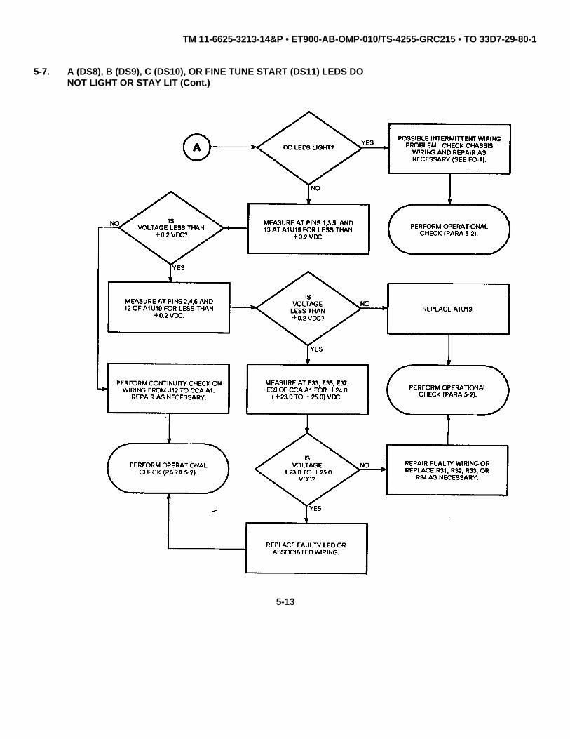
5-7. A (DS8), B (DS9), C (DS10), OR FINE TUNE START (DS11) LEDSDO NOT LIGHT OR STAY LIT
Refer to paragraph 5-5 for initial setup illustration and test equipment listing.
5-12
TM 11-6625-3213-14&P • ET900-AB-OMP-010/TS-4255-GRC215 • TO 33D7-29-80-1
5-7. A (DS8), B (DS9), C (DS10), OR FINE TUNE START (DS11) LEDS DONOT LIGHT OR STAY LIT (Cont.)
5-13

TM 11-6625-3213-14&P • ET900-AB-OMP-010/TS-4255-GRC215 • TO 33D7-29-80-1
5-8. PTT 100W (DS12) OR TUNE (DS13) LEDS DO NOT LIGHT OR STAY LIT
Refer to paragraph 5-5 for initial setup illustration and test equipment listing.
5-14

TM 11-6625-3213-14&P • ET900-AB-OMP-010/TS-4255-GRC215 • TO 33D7-29-80-1
5-8. PTT 100W (DS12) OR TUNE (DS13) LEDS DO NOT LIGHT OR STAY LIT(Cont.)
5-15

TM 11-6625-3213-14&P • ET900-AB-OMP-010/TS-4255-GRC215 • TO 33D7-29-80-1
5-9. 50 OHM (DS4), 100W PA BYPASS (DS5), OR ATTEN SELECT (DS6) LEDSDO NOT LIGHT OR STAY LIT
Refer to paragraph 5-5 for initial setup illustration and test equipment listing.
5-16

TM 11-6625-3213-14&P • ET900-AB-OMP-010/TS-4255-GRC215 • TO 33D7-29-80-1
5-9. 50 OHM (DS4), 100W PA BYPASS (DS5), OR ATTEN SELECT (DS6) LEDS DO NOT LIGHT OR STAY LIT (Cont.)
5-17

TM 11-6625-3213-14&P • ET900-AB-OMP-010/TS-4255-GRC215 • TO 33D7-29-80-1
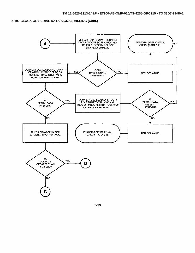
5-10. CLOCK OR SERIAL DATA SIGNAL MISSING
Refer to paragraph 5-5 for initial setup illustration and test equipment listing.
5-18
TM 11-6625-3213-14&P • ET900-AB-OMP-010/TS-4255-GRC215 • TO 33D7-29-80-1
5-10. CLOCK OR SERIAL DATA SIGNAL MISSING (Cont.)
5-19

TM 11-6625-3213-14&P • ET900-AB-OMP-010/TS-4255-GRC215 • TO 33D7-29-80-1
5-10. CLOCK OR SERIAL DATA SIGNAL MISSING (Cont.)
5-20

TM 11-6625-3213-14&P • ET900-AB-OMP-010/TS-4255-GRC215 • TO 33D7-29-80-1
5-11. R/E BITE TEST FUNCTION DOES NOT OPERATE
Refer to paragraph 5-5 for initial setup illustration and test equipment listing.
5-21

TM 11-6625-3213-14&P • ET900-AB-OMP-010/TS-4255-GRC215 • TO 33D7-29-80-1
5-12. OUT OF RANGE LED (DS14) FAULTY
Refer to paragraph 5-5 for initial setup illustration and test equipment listing.
5-22

TM 11-6625-3213-14&P • ET900-AB-OMP-010/TS-4255-GRC215 • TO 33D7-29-80-1
5-12. OUT OF RANGE LED (DS14) FAULTY (Cont.)
5-23

TM 11-6625-3213-14&P • ET900-AB-OMP-010/TS-4255-GRC215 • TO 33D7-29-80-1
5-13. REMOVAL/REPLACEMENT OF FRONT PANEL AND COMPONENTS
WARNING
All Removal/Replacement procedures are performed with powerremoved. For safety purposes disconnect power cables before beginningprocedures.
REMOVAL:
1. Remove 14 cross-tip screws 1 and flatwashers 2 securing front panel 3 to case 4 .
2. Lift front panel 3 away from case 4 .
3. Position front panel so component to be replaced is accessible.
4. Tag and unsolder wires from components being replaced.
5. Loosen and remove any hardware securing component to front panel and remove component.
REPLACEMENT:
1. Position component in front panel.
2. Replace and tighten any hardware that secures component to front panel.
3. Solder wires to replacement component and remove tags.
4. Position front panel 3 in case 4 .
5. Tighten 14 cross-tip screws 1 and flatwashers 2 that attach front panel 3 to case 4 .
6. Perform Operational Check (para. 5-2).
5-24

TM 11-6625-3213-14&P • ET900-AB-OMP-010/TS-4255-GRC215 • TO 33D7-29-80-1
5-13. REMOVAL/REPLACEMENT OF FRONT PANEL AND COMPONENTS (Cont.)
Figure 5-5. Front Panel Removal/Replacement
5-25/(5-26 Blank)

TM 11-6625-3213-14&P • ET900-AB-OMP-010/TS-4255-GRC215 • TO 33D7-29-80-1
SECTION VI.
PREPARATION FOR STORAGE OR SHIPMENT
6-1. GENERAL
a. Army. Administrative storage of equipment issued to and used by Army activities will have preventivemaintenance performed in accordance with the PMCS charts before storing. When removing the equipment fromadministrative storage the PMCS should be performed to assure operational readiness.
b. Navy. Refer to NAVSUP PUB 503.
c. Air Force. Refer to AFM 66-267 (storage) and AFR 67-31 (shipment).
6-2. MARKING
The marking on the exterior of the container shall be in accordance with MIL-STD-129H.
6-1/(6-2 Blank)

TM 11-6625-3213-14&P • ET900-AB-OMP-010/TS-4255-GRC215 • TO 33D7-29-80-1
APPENDIX A
REFERENCES
A-1. SCOPE
This appendix lists publications that are referenced in this manual that contain information applicable to themaintenance of the Manpack R/E Test Set TS-4255/GRC-215.
A-2. PUBLICATIONS
Air Force Suggestion Program ....................................................................................................................................... AFR 900-4
Consolidated Index of Army Publications and Blank Forms.....................................................................................DA Pam 25-30
First Aid for Soldiers ......................................................................................................................................................... FM 21-11
Maintenance Management Policy .................................................................................................................................... AFR 66-1
Marking for Shipment and Storage.......................................................................................................................... MIL-STD-129H
Procedures for Destruction of ElectronicsMateriel to Prevent Enemy Use(Electronics Command) .......................................................................................................................................TM 750-224-2
Product Quality Deficiency Report........................................................................................................................................ SF 368
Report of Discrepancy (ROD) .............................................................................................................................................. SF 364
Reporting of Item and Packaging Discrepancies ........................................................................................SECNAVINST 4355.18
Reporting of Transportation Discrepancies in Shipment .......................................................................... NAVSUPINST 4610.33C
Ships Maintenance and Material Management (3-M)
Manual, Promulgation of .............................................................................................................................. OPNAVINST 4790.2A
The Army Maintenance Management System (TAMMS).....................................................................................DA Pam 738-750
Transportation Discrepancy Report (TDR)........................................................................................................................... SF 361
Unit, Intermediate Direct Support, andGeneral Support Maintenance Manual ForReceiver-Transmitter, Radio RT-1511/GRC-215(NSN 5895-01-205-6180)...............................................................................................................................TM 11-5895-1318-24
Navy EE150-LS-MMI-010/Wl10-RT1511Air Force TO 31R2-2GRC215-42
Unsatisfactory Equipment Reporting..........................................................................................................................TO-00-35D54
A-1/(A-2 Blank)

TM 11-6625-3213-14&P • ET900-AB-OMP-010/TS-4255-GRC215 • TO 33D7-29-80-1
APPENDIX B
MAINTENANCE ALLOCATION CHART
B-1. GENERAL
This appendix provides a summary of the maintenance operations for the Manpack R/E Test Set TS-4255/GRC-215. Itauthorizes levels of maintenance for specific maintenance functions on repairable items and components and the toolsand equipment required to perform each function. This appendix may be used as an aid in planning maintenanceoperations.
B-2. MAINTENANCE FUNCTION
Maintenance functions will be limited to and defined as follows:
a. Inspect. To determine the serviceability of an item by comparing its physical, mechanical, and/or electricalcharacteristics with established standards through examination.
b. Test. To verify serviceability and to detect incipient failure by measuring the mechanical or electricalcharacteristics of an item and comparing those characteristics with prescribed standards.
c. Service. Operations required periodically to keep an item in proper operating condition, i.e., to clean(decontaminate), to preserve, to drain, to paint, or to replenish fuel, lubricants, hydraulic fluids, or compressed air supplies.
d. Adjust. To maintain, within prescribed limits, by bringing into proper or exact position, or by setting the operatingcharacteristics to the specified parameters.
e. Aline. To adjust specified variable elements of an item to bring about optimum or desired performance.
f. Calibrate. To determine and cause corrections to be made or to be adjusted on instruments or test measuringand diagnostic equipments used in precision measurement. Consists of comparisons of two instruments, one of which isa certified standard of known accuracy, to detect and adjust any discrepancy in the accuracy of the instrument beingcompared.
g. Install. The act of emplacing, seating, or fixing into position an item, part, module (component or assembly) in amanner to allow the proper functioning of the equipment or system.
h. Replace. The act of substituting a serviceable like type part, subassembly, or module (component or assembly)for an unserviceable counterpart.
B-1

TM 11-6625-3213-14&P • ET900-AB-OMP-010/TS-4255-GRC215 • TO 33D7-29-80-1
i. Repair. The application of maintenance services (inspect, test, service, adjust, aline, calibrate, replace) or othermaintenance actions (welding, grinding, riveting, straightening, facing, remachining, or resurfacing) to restore serviceabilityto an item by correcting specific damage, fault, malfunction, or failure in a part, subassembly, module (component orassembly), end item, or system.
j. Overhaul. That maintenance effort (service/action) necessary to restore an item to a completelyserviceable/operational condition as prescribed by maintenance standards (i.e., DMWR) in appropriate technicalpublications. Overhaul is normally the highest degree of maintenance performed by the Army. Overhaul does notnormally return an item to like new condition.
k. Rebuild. Consists of those services/actions necessary for the restoration of unserviceable equipment to a like newcondition in accordance with original manufacturing standards. Rebuild is the highest degree of material maintenanceapplied to Army equipment. The rebuild operation includes the act of returning to zero those age measurements (hours,miles, etc.) considered in classifying Army equipments/components.
B-3. COLUMN ENTRIES
a. Column 1. Group Number. Column 1 lists group numbers, the purpose of which is to identify components,assemblies, subassemblies, and modules with the next higher assembly.
b. Column 2, Component/Assembly. Column 2 contains the noun names of components, assemblies,subassemblies, and modules for which maintenance is authorized.
c. Column 3. Maintenance Functions. Column 3 lists the functions to be performed on the item listed in column 2.When items are listed without maintenance functions, it is solely for purpose of having the group numbers in the MAC andRPSTL coincide.
d. Column 4, Maintenance Level. Column 4 specifies, by the listing of a work time figure in the appropriatesubcolumn(s), the lowest level of maintenance authorized to perform the function listed in column 3. This figurerepresents the active time required to perform that maintenance function at the indicated level of maintenance. If thenumber or complexity of the tasks within the listed maintenance function vary at different maintenance levels, appropriatework time figures will be shown for each category. The number of task-hours specified by the work time figure representsthe average time required to restore an item (assembly, subassembly, component, module, end item, or system) to aserviceable condition under typical field operating conditions. This time includes preparation time, troubleshooting time,and quality assurance/quality control time in addition to the time required to perform the specific tasks identified for themaintenance functions authorized in the maintenance allocation chart. Subcolumns of column 4 are as follows:
B-2
TM 11-6625-3213-14&P • ET900-AB-OMP-010/TS-4255-GRC215 • TO 33D7-29-80-1
UNIT
C - Operator/CrewO - Organizational/Unit
INTERMEDIATE
F -.Direct SupportH - General SupportL - Special Repair Activity (SRA)
DEPOT
D -.Depot
e. Column 5. Tools and Equipment. Column 5 specifies by code, those common tool sets (not individual tools) andspecial tools, test, and support equipment required to perform the designated function.
f. Column 6. Remarks. Column 6 contains an alphabetic code which leads to the remark in section IV, Remarks,which is pertinent to the item opposite the particular code.
B-4. TOOL AND TEST EQUIPMENT REQUIREMENTS (SECT. III)
a. Tool or Test Equipment Reference Code. The numbers in this column coincide with the numbers used in the toolsand equipment column of the MAC. The numbers indicate the applicable tool or test equipment for the maintenancefunctions.
b. Maintenance Level. The codes in this column indicate the maintenance level allocated to tool or test equipment.9
c. Nomenclature. This column lists the noun name and nomenclature of the tools and test equipment required toperform the maintenance functions.
d. National/NATO Stock Number. This column lists the National/ NATO stock number of the specific tool or testequipment.
e. Tool Number. This column lists the manufacturer’s part number of the tool followed by the Federal Supply Codefor manufacturers (5-digit) in parentheses.
B-5. REMARKS (SECT. IV)
a. Reference Code. This code refers to the appropriate item in section II, column 6.
b. Remarks. This column provides the required explanatory information necessary to clarify items appearing insection II.
B-3
TM 11-6625-3213-14&P • ET900-AB-OMP-010/TS-4255-GRC215 • TO 33D7-29-80-1
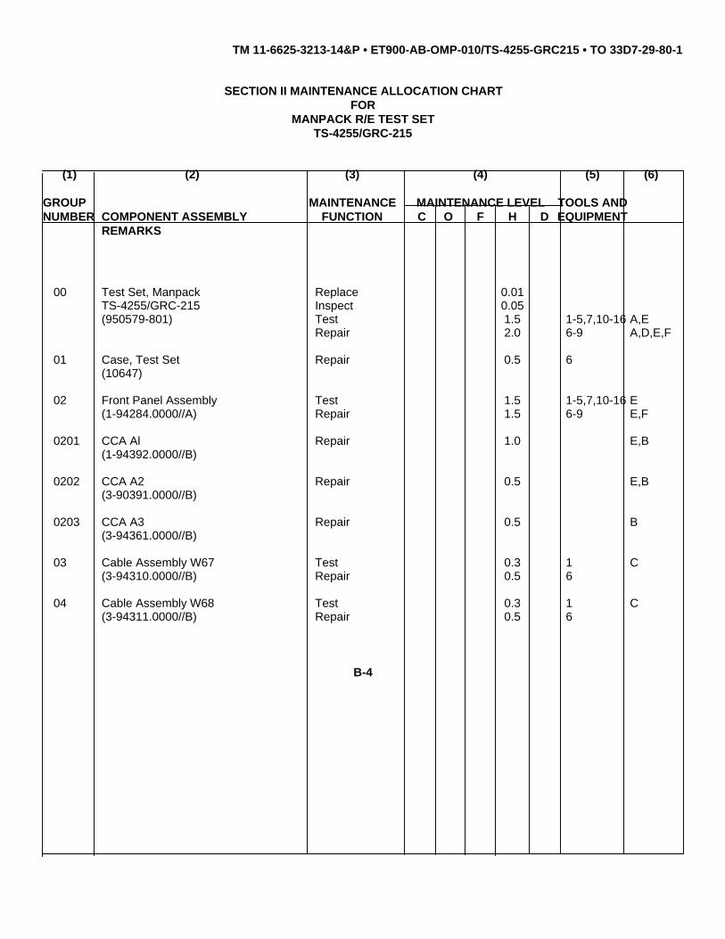
SECTION II MAINTENANCE ALLOCATION CHARTFOR
MANPACK R/E TEST SETTS-4255/GRC-215
(1) (2) (3) (4) (5) (6)
GROUP MAINTENANCE MAINTENANCE LEVEL TOOLS ANDNUMBER COMPONENT ASSEMBLY FUNCTION C O F H D EQUIPMENT
REMARKS
00 Test Set, Manpack Replace 0.01TS-4255/GRC-215 Inspect 0.05(950579-801) Test 1.5 1-5,7,10-16 A,E
Repair 2.0 6-9 A,D,E,F
01 Case, Test Set Repair 0.5 6(10647)
02 Front Panel Assembly Test 1.5 1-5,7,10-16 E(1-94284.0000//A) Repair 1.5 6-9 E,F
0201 CCA Al Repair 1.0 E,B(1-94392.0000//B)
0202 CCA A2 Repair 0.5 E,B(3-90391.0000//B)
0203 CCA A3 Repair 0.5 B(3-94361.0000//B)
03 Cable Assembly W67 Test 0.3 1 C(3-94310.0000//B) Repair 0.5 6
04 Cable Assembly W68 Test 0.3 1 C(3-94311.0000//B) Repair 0.5 6
B-4

TM 11-6625-3213-14&P • ET900-AB-OMP-010/TS-4255-GRC215 • TO 33D7-29-80-1
SECTION III. TOOL AND TEST EQUIPMENT REQUIREMENTS
FORMANPACK R/E TEST SET
TS-4255/GRC-215
REFERENCE MAINTENANCE NATIONAL/NATO TOOL*CODE LEVEL NOMENCLATURE STOCK NUMBER NUMBER
1 H Multimeter, Digital AN/USM-486 6625-01-145-2430 FLUKE 8050A-01
2 H Power Supply PP-8202/G * 6130-00-160-0827 HP 6274B
3 H Power Supply PP-3940B 6130-01-164-0548 POWER-10 4006
4 H Function Generator SG-1133/U 6625-01-028-4989 HP 3312A
5 H Frequency Counter AN/USM-459 6625-01-061-8928 HP 5328A-10/11/30/41
6 H Tool Kit, Elect. TK-17 5180-01-195-0855 JENSEN(Incl. Metric) JTK-17RM
7 H Workstation, Static 4940-01-087-3458 3M 8021
8 H Repair Kit, PCB MK-772/U 5999-00-757-7042
9 H Maintenance Kit, PCB MX-10897/G 5895-01-267-9473 PACE ModelRNR PIN
8007-0117
10 H Oscilloscope AN/USM-488 6625-01-187-7847 TEKTRONIX2235L
11 H Cable Assembly, DC Power W1 ** 569712-801//B
12 H Lead, Test Minigrabber 6625-01-040-0572 ITT POMONATest Clips to BNC Male 3787-C-48
13 H Cable Assembly, RG-58C/U 5995-00-724-4232 ITT POMONABNC Male Each End 2249-C -48
14 H Test CLip to Double Banana Plug 6625-01-013-0884 ITT POMONA3786-C-48
15 H Resistor, 620 Ohm + 20X, 1/4W
16 H Resistor, 10K Ohm + 20Z, 114W(6 Ea.)
* PP-8202/G(NSN6130-00-0028) provides identical capability when source power is 230V, 50 cycle. Air Force use only.
** It is part of the test set.
B-5

TM 11-6625-3213-14&P • ET900-AB-OMP-010/TS-4255-GRC215 • TO 33D7-29-80-1
SECTION IV.REMARKS
TEST SET, MANPACKTS-4255/GRC-215
ReferenceCode Remarks
A Consists of test repair to front panel assembly and cable assemblies. Includes performanceperformance check.
B Test/repair as part of next higher assembly.
C Consists of point-to-point continuity checks.
D Cable assembly, W1 (569712.801//B) is not repairable.
E Electrostatic sensitive devices.
F Piece part repair.
B-6

TM 11-6625-3213-14&P • ET900-AB-OMP-010/TS-4255-GRC215 • TO 33D7-29-80-1
APPENDIX COPERATOR'S, UNIT,
DIRECT SUPPORT AND GENERAL SUPPORT MAINTENANCEMANUAL INCLUDING REPAIR PARTS AND SPECIAL TOOLS LIST
TABLE OF CONTENTS
Page Illus Figure
Section I. INTRODUCTION.................................................. C-2
II. REPAIR PARTS LIST .......................................... C-1-1Group 00 Test Set, Manpack TS-4255/GRC-215
(950579-801) ................................................. C-1-1 C-101 Case Assembly (10647)....................................... C-2-1 C-202 Front Panel Assembly
(1-94284.0000//A).......................................... C-3-1 C-30201 CCA A1 (1-94392.0000//B)....................... C-4-1 C-40202 CCA A2 (3-90391.0000//B)....................... C-5-1 C-50203 CCA A3 (3-94361.0000//B)....................... C-6-1 C-6
03 Cable Assembly, W67(3-94310.0000//B).......................................... C-7-1 C-7
04 Cable Assembly, W68(3-94311.0000//B).......................................... C-8-1 C-8
Section III. Special Tools(Not applicable)
IV. Cross Reference IndexesNational Stock Number Index........................ C-I-1Part Number Index......................................... C-I-2Figure and Item Number Index...................... C-I-6
C-1

TM 11-6625-3213-14&P
APPENDIX C
OPERATOR’S, UNIT, DIRECT SUPPORT, AND GENERAL SUPPORT MAINTENANCEREPAIR PARTS AND SPECIAL TOOLS LIST
INTRODUCTION
C-1. Scope
This appendix lists and authorizes spares and repair parts; special tools; special test, measurement, and diagnosticequipment (TMDE); and other special support equipment required for performance of general support maintenance of theTS-4255/GRC-215. It authorizes the requisitioning, issue, and disposition of spares, repair parts and special tools asindicated by the source, maintenance and recoverability (SMR) codes.
C-2. General
This Repair Parts and Special Tools List is divided into the following sections:
a. Section II. Repair Parts List. A list of spares and repair parts authorized by this RPSTL for use in the performanceof maintenance. The list also includes parts which must be removed for replacement of the authorized parts. Parts listsare composed of functional groups in ascending numeric sequence, with the parts in each group listed in ascending itemnumber sequence. Figure numbers are listed directly beneath the group header.
b. Section III. Special Tools List. Not applicable.
c. Section IV. Cross-Reference Indexes. A list, in National item identification number (NIIN) sequence, of allNational stock numbered items appearing in the listing, followed by a list in alphameric sequence of all part numbersappearing in the listings. National stock numbers and part numbers are cross-referenced to each illustration figure anditem number appearance. The figure number and item number index list figure and item numbers in numeric sequenceand cross-references National stock number, Commercial and Government Entity Code, and part numbers.
C-3. Explanation of Columns (Section II and III)
a. Item No. (Column (1)). Indicates the number used to identify items called out in the illustration.
C-2

TM 11-6625-3213-14&P
b. SMR Code (Column (21). The source, maintenance, and recoverability (SMR) code is a five-position codecontaining supply/requisitioning information, maintenance category authorization criteria, and disposition instruction, asshown in the following breakout:
NOTEComplete repair: Maintenance capacity, capability, and authority toperform all corrective maintenance tasks of the "repair" function in ause/user environment in order to restore serviceability to a failed item.
(1) Source code. The source code tells you how to get an item needed for maintenance, repair, or overhaul ofan end item/equipment. Explanations of source codes follows:
Code Explanation
Stocked items: use the applicable NSN to request/requisition items withthese source codes. They are authorized to the category indicated by thecode entered in the third position of the SMR code.
NOTEItems coded PC are subject to deterioration.
Items with these codes are not to be requested/requisitioned individually.They are part of a kit which is authorized to the maintenance categoryindicated in the third position of the SMR code. The complete kit must berequistioned and applied.
C-3

TM 11-6625-3213-14&P
Code Explanation
Items with these codes are not to be requested/requisitioned individually.They must be made from bulk material which is identified by the partnumber in the description and usable on code (UOC) column and listedin the Bulk Material group of the repair parts list. If the item isauthorized to you by the third position code of the SMR code, but thesource code indicates it is made at a higher category, order the itemfrom the higher category of maintenance.
Items with these codes are not to be requested/requisitioned individually.The parts that make up the assembled item must be requisitioned orfabricated and assembled at the category of maintenance indicated bythe source code. If the third position code of the SMR code authorizesyou to replace the item, but the source code indicates the item isassembled at a higher category, order the item from the highercategory of maintenance.
Code Explanation
XA - Do not requisition an "XA" coded item. Order its next higher assembly.XB - If an "XB" item is not available from salvage, order it using the CAGEC and part number given.XC - Installation drawing, diagram, instruction sheet, field service drawing, that is identified by manufacturer’s part
number.XD - Item is not stocked. Order an "XD" coded item through normal supply channels using the CAGEC and part
number given, if no NSN is available.
NOTECannibalization or controlled exchange, when authorized, may be usedas a source of supply for items with the above source codes, except forthose source coded "XA" or those aircraft support items restricted byrequirements of AR 750-1.
C-4

TM 11-6625-3213-14&P
(2) Maintenance code. Maintenance codes tell you the category of maintenance authorized to USE and REPAIRsupport items. The maintenance codes are entered in the third and fourth positions of the SMR code as follows:
(a) The maintenance code entered in the third position tells you the lowest maintenance categoryauthorized to remove, replace, and use an item. The maintenance code entered in the third position will indicateauthorization to one of the following categories of maintenance.
Code Application/ExplanationC Crew or operator maintenance done within organizational or aviation maintenance.O Organizational or aviation unit category can remove, replace, and use the item.F Direct support or aviation intermediate category can remove, replace, and use the item.H General support category can remove, replace, and use the item.L Specialized repair activity can remove, replace, and use the item.D Depot category can remove, replace, and use the item.
(b) The maintenance code entered in the fourth position tells whether or not the item is to be repaired andidentifies the lowest maintenance category with the capability to do complete repair (i.e., perform all authorized repairfunctions). This position will contain one of the following maintenance codes.
NOTESome limited repair may be done on the item at a lower category ofmaintenance, if authorized by the Maintenance Allocation Chart (MAC)and SMR codes.
Code Application/Explanation
O - Organizational or aviation unit is the lowest category that can do complete repair of the item.F - Direct support or aviation intermediate is the lowest category that can do complete repair of the item.H - General support is the lowest category that can do complete repair of the item.L - Specialized repair activity (designate the specialized repair activity) is the lowest category that can do
complete repair of the item.D - Depot is the lowest category that can do complete repair of the item.
C-5

TM 11-6625-3213-14&P
Code Application/Explanation
Z - Nonreparable. No repair is authorized.B - No repair is authorized. (No parts or special tools are authorized for the maintenance of a "B" coded
item.) However, the item may be reconditioned by adjusting, lubricating, etc., at the user category.
(3) Recoverability code. Recoverability codes are assigned to items to indicate the disposition action onunserviceable items. The recoverability code is entered in the fifth position of the SMR Code as follows:
Recoverabilitycodes Application/Explanation
Z - Nonreparable item. When unserviceable, condemn and dispose of the item at the category ofmaintenance shown in the third position of SMR code.
O - Reparable item. When uneconomically reparable, condemn and dispose of the item at organizational oraviation unit category.
F - Reparable item. When uneconomically reparable, condemn and dispose of the item at direct support oraviation intermediate category.
H - Reparable item. When uneconomically reparable, condemn and dispose of the item at general supportcategory.
D - Reparable item. When beyond lower category repair capability, return to depot. Condemnation anddisposal of item not authorized below depot category.
L - Reparable item. Condemnation and disposal not authorized below specialized repair activity (SRA).A - Item requires special handling or condemnation procedures because of specific reasons (e.g., precious
metal content, high dollar value, critical material, or hazardous material). Refer appropriatemanuals/directives for specific instructions.
c. CAGEC (Column (3)). The Commercial and Government Entity Code (CAGEC) is a 5-digit numeric codewhich is used to identify the manufacturer, distributor, or Government agency, etc., that supplies the item.
d. Part Number (Column (4)). Indicates the primary number used by the manufacturer (individual, company, firm,corporation, or Government activity), which controls the design and characteristics of the item by means of its engineeringdrawings, specifications, standards, and inspection requirements to identify an item or range of items.
C-6

TM 11-6625-3213-14&P
NOTEWhen you use an NSN to requisition an item, the item you receive mayhave a different part number from the part ordered.
e. Description and Usable on Code (UOC) (Column (5)). This column includes the following information.
(1) The Federal item name and, when required, a minimum description to identify the item.
(2) The statement "END OF FIGURE" appears just below the last item description in Column (5) for a givenfigure in both section II and section III.
f. Qty (Column (6)). Indicates the quantity of the item used in the breakout shown on the illustration figure, which isprepared for a functional group, subfunctional group, or an assembly. A "V" appearing in this column in lieu of aquantity indicates that the quantity is variable and the quantity may vary from application to application.
C-4. Explanation of Columns (Section IV)
a. National Stock Number (NSN) Index.
(1) Stock number column. This column lists the NSN by National item identification number (NIIN) sequence.The NIIN consists of the last nine digits of the NSN. When using this column to locate an item, ignore the first four digits ofthe NSN. When requisitioning items use the complete NSN (13 digits).
(2) Fig. column. This column lists the number of the figure where the item is identified/located. The illustrationsare in numerical sequence in sections II and III.
(3) Item column. The item number identifies the item associated with the figure listed in the adjacent Fig.column. This item is also identified by the NSN listed on the same line.
b. Part Number Index. Part numbers in this index are listed by part number in ascending alphameric sequence.
(1) CAGEC column. This column lists the Commercial and Government Entity Code (CAGEC).
C-7

TM 11-6625-3213-14&P
(2) Part number column. This column indicates the part number assigned to the item.
(3) Stock number column. This column lists the National stock number for the associated part number andmanufacturer identified in the part number and CAGEC columns to the left.
(4) Fig. column. This column lists the number of the figure where the item is identified/located in sections II andIII.
(5) Item column. The item number is that number assigned to the item as it appears in the figure referenced inthe adjacent figure number column.
c. Figure and Item Number Index.
(1) Fig. column. This column lists the number of the figure where the item is identified/located in sections II andIII.
(2) Item column. The item number is that number assigned to the item as it appears in the figure referenced inthe adjacent figure number column.
(3) Stock number column. This column lists the National stock number for the item.
(4) CAGEC column. The Commercial and Government Entity Code (CAGEC) is a 5-digit numeric code used toidentify the manufacturer, distributor, or Government agency, etc., that supplies the item.
(5) Part number column. Indicates the primary number used by the manufacturer (individual, firm, corporation,or Government activity), which controls the design and characteristics of the item by means of its engineering drawings,specifications, standards, and inspection requirements to identify an item or range of item.
C-5. Special Information
National stock numbers (NSN’s) that are missing from P source coded items have been applied for and will be added tothis TM by future change/revision when they are entered in the Army Master Data File (AMDF). Until the NSN’s areestablished and published, submit exception requisitions to: Commander, US Army Communications-ElectronicsCommand and Fort Monmouth, ATTN: AMSEL-LC-MM, Fort Monmouth, NJ 07703-5000 for the part required to supportyour equipment.
NOTEAn item SMR coded "H" in the third, fourth, and fifth position is interpretedas intermediate for Air Force Repair.
C-8

TM 11-6625-3213-14&P
C-6. How to Locate Repair Parts
a. When National stock number or part number is not known.(1) First. Using the table of contents, determine the assembly group or subassembly group to which the item
belongs. This is necessary since figures are prepared for assembly groups and subassembly groups, and listings aredivided into the same groups.
(2) Second. Find the figure covering the assembly group or subassembly group to which the item belongs.
(3) Third. Identify the item on the figure and note the item number.
(4) Fourth. Refer to the Repair Parts List for the figure to find the part number for the item number noted on thefigure.
(5) Fifth. Refer to the Part Number Index to find the NSN, if assigned.
b. When National stock number or part number is known.
(1) First. Using the index of National stock numbers and part numbers, find the pertinent National stock numberor part number. The NSN index is in National item identification number (NITN) sequence (para C-4a(l)). The partnumbers in the part number index are listed in ascending alphameric sequence (para C-4b). Both indexes cross-reference you to the illustration figure and item number of the item you are looking for.
(2) Second. After finding the figure and item number, verify that the item is the one you’re looking for, thenlocate the item number in the repair parts list for the figure.
C-7. Abbreviations
Not applicable.
C-9

TM 11-6625-3213-14&P • ET900-AB-OMP-010/TS-4255-GRC215 • TO 33D7-29-80-1
Figure C-1. Test Set, Manpack TS-4255/GRC-215 (950579-801)

SECTION II TM 11-6625-3213-14&P(1) (2) (3) (4) (5) (6)
ITEM SMR PARTNO CODE CAGEC NUMBER DESCRIPTION AND USABLE ON CODES (UOC) QTY
GROUP 00 TEST SET,MANPACKTS-4255/GRC-215(950579-801)
FIG. C-1
1 XBHHH 24995 10647 CASE,TEST SET (SEE FIG.C-2 FOR ........................ 1PARTS BREAKDOWN)
2 PAHZZ A3026 569712.801//B CABLE,DC POWER..................................................... 13 PAHHH A3026 3-94310.0000//B CABLE ASSEMBLY,POWE (SEE FIG.C-7................. 1
FOR PARTS BREAKDOWN).4 PAHHH A3026 3-94311.0000//B CABLE ASSEMBLY,POWE (SEE FIG.C-8................. 1
FOR PARTS BREAKDOWN).5 XBHLL A3026 1-94284.0000//A PANEL ASSEMBLY (SEE FIG.C3 FOR...................... 1
PARTS BREAKDOWN)6 PAHZZ 96906 MS51957-45 SCREW,MACHINE ...................................................... 147 PAHZZ 88044 AN960C8L WASHER,FLAT............................................................ 148 XBHZZ A3026 4-A2155.0009//D PLATE,IDENTIFICATIO............................................... 2
END OF FIGURE
C-1-1

TM 11-6625-3213-14&P • ET900-AB-OMP-010/TS-4255-GRC215 • TO 33D7-29-80-1
Figure C-2. Case Assembly (10647)

SECTION II TM 11-6625-3213-14&P(1) (2) (3) (4) (5) (6)
ITEM SMR PARTNO CODE CAGEC NUMBER DESCRIPTION AND USABLE ON CODES (UOC) QTY
GROUP 01 CASE ASSEMBLY (10647)FIG. C-2
1 XBHZZ 24995 22002022 LATCH.......................................................................... 22 XBHZZ 24995 33500035 RIVET ASSEMBLY ...................................................... 193 XBHZZ 24995 31000691 HANDLE,BOW ............................................................. 14 XBHZZ 24995 24000450 HINGE.......................................................................... 15 XBHZZ 24995 24000460 HINGE.......................................................................... 1
END OF FIGURE
C-2-1

TM 11-6625-3213-14&P • ET900-AB-OMP-010/TS-4255-GRC215 • TO 33D7-29-80-1
Figure C-3. Front Panel Assembly (1-94284.0000//A) (Sheet 1 of 5)

TM 11-6625-3213-14&P • ET900-AB-OMP-010/TS-4255-GRC215 • TO 33D7-29-80-1
Figure C-3. Front Panel Assembly (1-94284.0000//A) (Sheet 2 of 5)

TM 11-6625-3213-14&P • ET900-AB-OMP-010/TS-4255-GRC215 • TO 33D7-29-80-1
Figure C-3. Front Panel Assembly (1-94284.0000//A) (Sheet 3 of 5)

TM 11-6625-3213-14&P • ET900-AB-OMP-010/TS-4255-GRC215 • TO 33D7-29-80-1
Figure C-3. Front Panel Assembly (1-94284.0000//A) (Sheet 4 of 5)

TM 11-6625-3213-14&P • ET900-AB-OMP-010/TS-4255-GRC215 • TO 33D7-29-80-1
Figure C-3. Front Panel Assembly (1-94284.0000//A) (Sheet 5 of 5)

SECTION II TM 11-6625-3213-14&P(1) (2) (3) (4) (5) (6)
ITEM SMR PARTNO CODE CAGEC NUMBER DESCRIPTION AND USABLE ON CODES (UOC) QTY
GROUP 02 FRONT PANEL ASSEMBLY(1-94284.0000//A)
FIG. C-3
1 XBHHH A3026 1-A2144.0000//A FRONT PANEL ............................................................ 12 PAHZZ 18323 990C758H03 POST,BINDING,ELECTR ............................................ 13 PAHZZ A3026 4-36509.0001//C BINDING POST,ELECTR ............................................ 34 PAHZZ A3026 3-10284.0109//C TERMINAL,LUG........................................................... 65 PAHZZ A3026 4-36246.0000//N JACK,TIP...................................................................... 106 PAHZZ A3026 4-06746.0000//N JACK,TIP...................................................................... 17 PAHZZ 96906 MS51959-3 SCREW,MACHINE ...................................................... 128 PAHZZ 91812 D36BA1GLRSP SWITCH,ROTARY ....................................................... 59 PAHZZ A3026 4-32151.0004//M SWITCH,TOGGLE ....................................................... 16
10 XBHZZ 80063 A3034572 LABEL--ELECTROSTATE ........................................... 111 PAHZZ A3026 4-32150.0003//M SWITCH,PUSH BUTTON ............................................ 412 PAHZZ A3026 4-32151.0005//M SWITCH,TOGGLE ....................................................... 213 PAHZZ 91812 28165 SWITCH,ROTARY ....................................................... 114 PAHZZ A3026 4-55268.0003//G RESISTOR,FIXED,COMP ........................................... 115 PAHZZ 49956 70-4-1G KNOB ........................................................................... 216 PAHZZ A3026 4-34260.0000//M HOLDER,LAMP............................................................ 2017 PAHZZ 80063 A3027517 SEMICONDUCTOR DEVI............................................ 1418 PAHZZ 81349 FHN20G FUSEHOLDER,EXTRACTO ........................................ 119 PAHZZ A3026 4-05861.0020//Q FUSE,CARTRIDGE ..................................................... 120 PAHZZ A3026 4-36509.0002//C BINDING POST,ELECTR ............................................ 321 PAHZZ A3026 4-A2173.0000//G POTENTIOMETER ...................................................... 122 PAHZZ 49956 481660-1 CONNECTOR,RECEPTACL ....................................... 123 PAHZZ 81349 M39012/24-0002 CONNECTOR,RECEPTACL ....................................... 624 PAHZZ 28480 HLMP-3507 LIGHT EMITTING DIOD .............................................. 625 PAHZZ A3026 DDMY-43W2S CONNECTOR,RECEPTACL ....................................... 126 PAHZZ 71785 DM53740-5008 CONTACT,ELECTRICAL............................................. 227 PAHZZ 58189 555146-074 CONNECTOR,PLUG,ELEC......................................... 128 XBHZZ A3026 4-A2155.0009//D PLATE,IDENTIFICATIO............................................... 129 PAHZZ A3026 503.10.0445.000/ CONNECTOR,RECEPTACL ....................................... 1
/N30 PAHZZ A3026 4-A2161.0000//D MOUNTING BASE,ELECT .......................................... 131 PAHZZ 96906 MS25036-146 TERMINAL,LUG........................................................... 732 XBHZZ A3026 4-A2158.0000//D BAND,MARKER........................................................... 233 PAHZZ 59730 TY23M(MS3367-4) STRAP,TIEDOWN,ELECT .......................................... 134 XBHHH A3026 4-94409.0000//B WIRING HARNESS ..................................................... 135 PAHZZ 96906 MS25036-103 TERMINAL,LUG........................................................... 436 PAHZZ A3026 3-A2131.0000//D SPACER....................................................................... 437 PAHZZ 96906 MS15795-803 WASHER,FLAT............................................................ 2938 PAHZZ A3026 3-75883-001 NUT,PLAIN,HEXAGON .............................................. . 1439 PAHZZ A3026 3-10311-003 WASHER,LOCK........................................................... 2940 PAHZZ 58135 RJ150-50 RESISTOR,FIXED,FILM .............................................. 441 XBHZZ A3026 3-A2147.0000//D HEATSINK,ELECTRICAL ............................................ 142 PAHZZ 96906 MS51957-13 SCREW,MACHINE ...................................................... 1843 PAHZZ 81349 RCR07G103JS RESISTOR,FIXED,COMP ........................................... 144 PAHZZ A3026 4-B3047.0000//C TERMINAL,FEEDTHRU .............................................. 345 PAHZZ 81349 M38510/10706BYA MICROCIRCUIT,LINEAR............................................. 1
C-3-1

SECTION II TM 11-6625-3213-14&P(1) (2) (3) (4) (5) (6)
ITEM SMR PARTNO CODE CAGEC NUMBER DESCRIPTION AND USABLE ON CODES (UOC) QTY
46 PAHZZ 80063 A3027095-1 HEAT SINK-INSULATOR.. .......................................... 147 PAHLL A3026 3-90391.0000//B CIRCUIT CARD ASSEMB (SEE FIG.C-5 .................... 1
FOR PARTS BREAKDOWN)48 PAHLL A3026 1-94392.0000//B CIRCUIT CARD ASSEMB (SEE FIG.C-4 .................... 1
FOR PARTS BREAKDOWN)49 XBHZZ A3026 2-A2146.0000//D PLATE.......................................................................... 150 PAHZZ 96906 MS51957-15 SCREW,MACHINE ...................................................... 451 PAHZZ 80063 A3027823 TERMINAL,LUG........................................................... 752 PAHZZ A3026 4-A2151.0000//C BUSHING..................................................................... 253 PAHZZ A3026 3-10539.0013//C WASHER,FLAT............................................................ 254 PAHLL A3026 3-94361.0000//B CIRCUIT CARD ASSEMB (SEE FIG.C-6 .................... 1
FOR PARTS BREAKDOWN)55 PAHZZ 96906 MS51957-14 SCREW,MACHINE ..................................................... 256 XBHZZ A3026 3-A2160.0000//D HEATSINK,ELECTRICAL ............................................ 157 PAHZZ 98291 011-2004 TERMINAL,FEEDTHRU .............................................. 258 PAHZZ 81349 JAN1N3957 SEMICONDUCTOR DEVIC ......................................... 159 PAHZZ 80063 A3026908-6 TERMINAL,LUG........................................................... 260 PAHZZ A3026 4-51249.0000//C BUSHING .................................................................... 261 PAHZZ 96906 MS51957-17 SCREW,MACHINE ...................................................... 262 PAHZZ 81349 M39014/02-1358 CAPACITOR,FIXED,CER ............................................ 163 PAHZZ 81349 M39014/01-1593 CAPACITOR,FIXED,CER ............................................ 164 XBHZZ A3026 1-A2145.0000//D PANEL,FRONT ........................................................... 165 PAHZZ 81349 M63540/1-9C STUD,SELF-LOCKING ................................................ 466 PAHZZ 80063 A3026906-3 TERMINAL,LUG........................................................... 167 PAHZZ 81349 M63540/1-6C STUD,SELF-LOCKING ................................................ 1
END OF FIGURE
C-3-2

TM 11-6625-3213-14&P • ET900-AB-OMP-010/TS-4255-GRC215 • TO 33D7-29-80-1
Figure C-4. CCA A1 (1-94392.0000//B) (Sheet 1 of 5)

TM 11-6625-3213-14&P • ET900-AB-OMP-010/TS-4255-GRC215 • TO 33D7-29-80-1
Figure C-4. CCA A1 (1-94392.0000//B) (Sheet 2 of 5)

TM 11-6625-3213-14&P • ET900-AB-OMP-010/TS-4255-GRC215 • TO 33D7-29-80-1
Figure C-4. CCA A1 (1-94392.0000//B) (Sheet 3 of 5)

TM 11-6625-3213-14&P • ET900-AB-OMP-010/TS-4255-GRC215 • TO 33D7-13-108-1
Figure C-4. CCA A1 (1-94392.0000//B) (Sheet 4 of 5)

TM 11-6625-3213-14&P • ET900-AB-OMP-010/TS-4255-GRC215 • TO 33D7-13-108-1
NOTE: ALL REF DESIGNATORS SHOULD BEPRECEDED BY AN A1 .
LEGEND
REF. ITEM REF. ITEM REF. ITEM REF. ITEM REF. ITEM REF. ITEMDES. NO. DES. NO. DES. NO. DES. NO. DES. NO. DES. NO.
CR1 1 C16 3 ML18 16 R14 26 R32 24 R50 19CR2 1 ML1 6 ML19 17 R15 26 R33 24 R51 19CR3 1 ML2 7 Q1 18 R16 26 R34 24 R52 19C1 2 ML3 7 Q2 18 R17 26 R35 24 R53 19C2 3 ML4 8 Q3 18 R18 26 R36 24 R54 19C3 3 ML5 9 R1 19 R19 24 R37 19 R55 19C4 4 ML6 10 R2 20 R20 24 R38 19 R56 19C5 3 ML7 10 R3 19 R21 24 R39 19 R57 19C6 3 ML8 10 R4 19 R22 24 R40 19 R58 19C7 3 ML9 10 R5 19 R23 24 R41 19 R59 28C8 4 ML10 10 R6 19 R24 24 R42 19 R60 21C9 4 ML11 10 R7 21 R25 24 R43 19 R61 29C10 4 ML12 11 R8 22 R26 24 R44 19 R62 19C11 4 ML13 12 R9 19 R27 24 R45 19 R63 21C12 3 ML14 12 R10 23 R28 24 R46 19 R64 21C13 5 ML15 13 R11 24 R29 27 R47 19 R65 21C14 3 ML16 14 R12 25 R30 27 R48 19 R66 21C15 4 ML17 15 R13 25 R31 24 R49 19 Y1 30
CE1VY-012
Figure C-4. CCA A1 (1-94392.0000//B) (Sheet 5 of 5)

SECTION II TM11-6625-3213-14&P(1) (2) (3) (4) (5) (6)
ITEM SMR PARTNO CODE CAGEC NUMBER DESCRIPTION AND USABLE ON CODES (UOC) QTY
GROUP 0201 CCA A1) (1-94392.0000//B)
FIG. C-4
1 PAHZZ 81349 JAN1N4454-1 SEMICONDUCTOR DEVIC ......................................... 32 PAHZZ 81349 M39014/01-1351 CAPACITOR, FIXED, CER .......................................... 13 PAHZZ 81349 M39014/01-1593 CAPACITOR, FIXED, CER .......................................... 84 PAHZZ 81349 M39014/01-1575 CAPACITOR, FIXED, CER .......................................... 65 PAHZZ 81349 M39014-01-1333 CAPACITOR, FIXED, CER .......................................... 16 PAHZZ 81349 M38510/10901BPB MICROCIRCUIT, LINEAR............................................ 17 PAHZZ 81349 M38510/00104BCB MICROCIRCUIT, DIGITA............................................. 28 PAHZZ 04713 MC6802S MICROCIRCUIT, DIGITA............................................. 19 PAHZZ A3026 4-59176.0107//P MICROCIRCUIT, DIGITA............................................. 1
10 PAHZZ 81349 M38510/32202BEB MICROCIRCUIT, DIGITA............................................. 611 PAHZZ 01295 SN7442J MICROCIRCUIT, DIGITA............................................. 112 PAHZZ 04713 6821/BQAJC MICROCIRCUIT, DIGITA............................................. 213 PAHZZ 04713 MC14490L MICROCIRCUIT, DIGITA............................................. 114 PAHZZ 02735 CD4050BD/3 MICROCIRCUIT, DIGITA............................................. 115 PAHZZ 02735 CD4027BE MICROCIRCUIT, DIGITA............................................. 116 PAHZZ 02735 7901401EB MICROCIRCUIT, DIGITA............................................. 117 PAHZZ 81349 M38510/00803BCB MICROCIRCUIT, DIGITA............................................. 118 PAHZZ 81349 JAN2N2222A TRANSISTOR .............................................................. 319 PAHZZ 81349 RCR05G103JS RESISTOR, FIXED, COMP ......................................... 2920 PAHZZ 81349 RCR05G302JS RESISTOR, FIXED, COMP ......................................... 121 PAHZZ 81349 RCR05G1002JS RESISTOR, FIXED, COMP ......................................... 622 PAHZZ 81349 RCR05G124JS RESISTOR, FIXED, COMP ......................................... 123 PAHZZ 81349 RCR05G221JS RESISTOR, FIXED, COMP ......................................... 124 PAHZZ 81349 RCR20G152JS RESISTOR, FIXED, COMP ......................................... 1725 PAHZZ 81349 RCR05G105JS RESISTOR, FIXED, COMP ......................................... 226 PAHZZ 81349 RCR05G472JS RESISTOR, FIXEB, COMP.......................................... 527 PAHZZ 81349 RCR05G104JS RESISTOR, FIXED, COMP ......................................... 228 PAHZZ 81349 RCR05G511JS RESISTOR, FIXED, COMP ......................................... 129 PAHZZ 81349 RCR05G203JS RESISTOR, FIXED, COMP ......................................... 130 PAHZZ 80063 A3026810-1 CRYSTAL, QUARTZ.................................................... 131 PAHZZ 06726 ICN-406-S5-G SOCKET....................................................................... 332 PAHZZ 06726 ICN-246-S4-G SOCKET....................................................................... 133 XBHZZ 80063 A3034571-3 LABEL, ELECTROSTATIC .......................................... 134 PAHZZ A3026 4-A2151.0000//C BUSHING..................................................................... 435 PAHZZ 58189 666273-074 TERMINAL, LUG.......................................................... 79
END OF FIGURE
C-4-1

TM 11-6625-3213-14&P • ET900-AB-OMP-010/TS-4255-GRC215 • TO 33D7-13-108-1
Figure C-5. CCA A2 (3-90391.0000//B)

SECTION II TM11-6625-3213-24&P(1) (2) (3) (4) (5) (6)
ITEM SMR PARTNO CODE CAGEC NUMBER DESCRIPTION AND USABLE ON CODES (UOC) QTY
GROUP 0202 CCA (A2)(1-90391.0000//B)
FIG. C-5
1 PAHZZ 81349 M39014/01-1593 CAPACITOR, FIXED, CER .......................................... 32 PAHZZ 81349 CLR65BB56OKGL CAPACITOR, FIXED, ELE........................................... 13 PAHZZ 31433 T370-D106M020AS CAPACITOR, FIXED, ELE........................................... 14 PAHZZ 31433 T372B225M010A5 CAPACITOR, FIXED, ELE........................................... 15 PAHZZ 31433 T372E336M006AS CAPACITOR, FIXED, ELE........................................... 26 PAHZZ 81349 M39014/02-1332 CAPACITOR, FIXED, CER .......................................... 17 PAHZZ 81349 M39014/02-1358 CAPACITOR, FIXED, CER .......................................... 18 PAHZZ A3026 696017.180//K INDUCTOR .................................................................. 29 PAHZZ 06481 971325-2102 MICROCIRCUIT, LINEAR............................................ 1
10 PAHZZ 07933 RM3503ADC3 MICROCIRCUIT, LINEAR............................................ 111 PAHZA 55154 5L6270C-CM MICROCIRCUIT, LINEAR............................................ 112 PAHZZ 02735 CD4050BD/3 MICROCIRCUIT, DIGITA............................................. 113 PAHZZ 81349 M38510/00803BCB MICROCIRCUIT, DIGITA............................................. 114 PAHZZ 81349 RCR05G202JS RESISTOR, FIXED, COMP ......................................... 215 PAHZZ 81349 RJR26FW503R RESISTOR, VARIABLE, N........................................... 116 PAHZZ 81349 RCR05G512JS RESISTOR, FIXED, COMP ......................................... 217 PAHZZ 81349 RCR05G105JS RESISTOR, FIXED, COMP ......................................... 118 PAHZZ 81349 RJR26FW103R RESISTOR, VARIABLE, N........................................... 119 PAHZZ 81349 RCR05G1003JS RESISTOR, FIXED, COMP ......................................... 120 PAHZZ 81349 RCR32G681JS RESISTOR, FIXED, COMP ......................................... 1721 PAHZZ 81349 M27/70-10 TRANSFORMER, AUDIO F......................................... 122 PAHZZ 81349 M38527/02-017D MOUNTING PAD, ELECTR ......................................... 123 PAHZZ 81349 M38527-1-18B1 MOUNTING PAD, ELECTR ......................................... 124 XBHZZ 80063 A3034571-3 LABEL, ELECTROSTATIC .......................................... 125 PAHZZ A3026 4-A2151.0000//C BUSHING..................................................................... 426 PAHZZ 58189 666273-074 TERMINAL, LUG.......................................................... 15
END OF FIGURE
C-5-1

TM 11-6625-3213-14&P • ET900-AB-OMP-010/TS-4255-GRC215 • TO 33D7-13-108-1
Figure C-6. CCA A3 (3-94361.0000//B)

SECTION II TM11-6625-3213-24&P(1) (2) (3) (4) (5) (6)
ITEM SMR PARTNO CODE CAGEC NUMBER DESCRIPTION AND USABLE ON CODES (UOC) QTY
GROUP 0203 CCA (A3)(1-94361.0000//B)
FIG. C-6
1 PAHZZ 81349 M39014/01-1568 CAPACITOR, FIXED, CER .......................................... 12 PAHZZ 81349 M39014/01-1354 CAPACITOR, FIXED, CER .......................................... 13 PAHZZ 81349 M39014/01-1566 CAPACITOR, FIXED, CER .......................................... 24 PAHZZ 81349 CKR05BX271KP CAPACITOR, FIXED, ELE........................................... 15 PAHZZ 81349 M39014/02-1332 CAPACITOR, FIXED, CER .......................................... 16 PAHZZ 96906 MS75084-12 COIL, RADIO FREQUENC .......................................... 27 PAHZZ 80063 A3030174 MIXER STAGE, FREQUEN ......................................... 18 XBHZZ A3026 4-B0886.0000//C FRAME......................................................................... 19 PAHZZ A3026 4-B0887.0000//C SHIELD, ELECTRICAL ................................................ 1
10 XBHZZ A3026 4-B0890.0000//C COVER......................................................................... 111 PAHZZ 58189 666273-074 TERMINAL, LUG.......................................................... 6
END OF FIGURE
C-6-1

TM 11-6625-3213-14&P • ET900-AB-OMP-010/TS-4255-GRC215 • TO 33D7-13-108-1
NOTE: ALL REF DESIGNATORS SHOULD BE PRECEDED BY AN W67 CE1VY-015
Figure C-7. Cable Assembly, W67 (3-94310.0000//B)

SECTION II TM11-6625-3213-24&P(1) (2) (3) (4) (5) (6)
ITEM SMR PARTNO CODE CAGEC NUMBER DESCRIPTION AND USABLE ON CODES (UOC) QTY
GROUP 03 CABLE ASSEMBLY (W67)(3-94310.0000//B)
FIG. C-7
1 PAHZZ 71468 DD51217 SHIELD, ELECTRICAL C............................................. 22 PAHZZ 18876 9073891-3 CONTACT, ELECTRICAL............................................ 23 PAHZZ A3026 DDMY-43W2S CONNECTOR, RECEPTACL ...................................... 14 PAHZZ 96214 531740-1 CONNECTOR, RECEPTACL ...................................... 15 PAHZZ 71785 DM53740-5008 CONTACT, ELECTRICAL............................................ 26 PAHZZ 18876 10125334-2 RETAINER, ELECTRICAL........................................... 1
END OF FIGURE
C-7-1

TM 11-6625-3213-14&P • ET900-AB-OMP-010/TS-4255-GRC215 • TO 33D7-13-108-1
NOTE: ALL REF DESIGNATORS SHOULD BE PRECEDED BY A W68 CE1VY-016
Figure C-8. Cable Assembly, W68 (3-94311.0000//B)

SECTION II TM11-6625-3213-24&P(1) (2) (3) (4) (5) (6)
ITEM SMR PARTNO CODE CAGEC NUMBER DESCRIPTION AND USABLE ON CODES (UOC) QTY
GROUP 04 CABLE ASSEMBLY (W68)(3-94311.0000//B)
FIG. C-8
1 XBHZZ 71468 DB51213-1 HOUSING..................................................................... 22 PAHZZ 81349 M24308/4-3 CONNECTOR, RECEPTACL ...................................... 23 PAHZZ 71468 DD51223-1 RETAINER, ELECTRICAL........................................... 1
END OF FIGURE
C-8-1

SECTION IV TM11-6625-3213-14&PCROSS- REFERENCE-INDEXES
NATIONAL STOCK NUMBER INDEXSTOCK NUMBER FIG. ITEM STOCK NUMBER FIG. ITEM
5910-00-010-8717 C-3 63 5935-00-896-9910 C-7 6C-4 3 5935-00-905-2740 C-8 3C-5 1 5935-00-948-2792 C-7 1
5999-00-021-2119 C-7 2 5961-00-965-9594 C-3 585950-00-031-4557 C-6 6 5935-00-997-8026 C-3 235940-00-045-6399 C-3 2 5962-01-033-2282 C-4 145305-00-054-5647 C-3 42 C-5 125305-00-054-5648 C-3 55 5905-01-035-5065 C-4 195305-00-054-5649 C-3 50 C-5 195305-00-054-5651 C-3 61 5962-01-069-3045 C-4 65305-00-054-6670 C-1 6 5950-01-078-6496 C-5 215910-00-098-9242 C-6 3 5999-01-080-1971 C-5 235905-00-106-3666 C-3 43 5910-01-100-8108 C-5 35905-00-111-4738 C-4 24 5962-01-101-1050 C-4 105910-00-113-5276 C-4 2 5962-01-110-5628 C-4 155910-00-113-5284 C-3 62 5962-01-151-4506 C-4 12
C-5 7 5905-01-161-7274 C-5 155910-00-113-5515 C-4 5 5962-01-164-8741 C-5 105910-00-113-9448 C-6 2 5980-01-178-0898 C-3 245910-00-124-0659 C-4 4 5905-01-184-3510 C-5 185910-00-143-0501 C-5 6 5895-01-185-5408 C-6 7
C-6 5 5307-01-188-5229 C-3 655940-00-143-4771 C-3 35 5307-01-194-3198 C-3 675910-00-166-6757 C-6 1 5999-01-194-9729 C-5 225905-00-177-7486 C-4 23 5962-01-195-1993 C-5 95905-00-195-4074 C-4 25 5930-01-241-4623 C-3 13
C-5 17 5905-01-244-6853 C-3 405905-00-197-0224 C-4 28 5962-01-274-1575 C-5 115905-00-235-3534 C-5 20 5999-01-276-5655 C-3 465962-00-318-2223 C-4 7 5940-01-276-7162 C-3 595962-00-369-9839 C-4 17
C-5 135935-00-402-1519 C-7 45905-00-413-1200 C-4 295905-00-421-8918 C-4 205905-00-458-9346 C-4 275905-00-458-9347 C-4 225905-00-458-9500 C-4 215905-00-470-9481 C-5 145935-00-489-9999 C-8 25920-00-556-0144 C-3 185310-00-558-6207 C-1 75940-00-578-3484 C-3 575310-00-595-6211 C-3 375905-00-617-5091 C-4 265355-00-656-1458 C-3 155905-00-689-1290 C-5 165305-00-727-8833 C-3 75940-00-804-0365 C-3 315935-00-823-0667 C-3 22
C-I-1

SECTION IV TM11-6625-3213-14&PNATIONAL STOCK NUMBER AND PART NUMBER INDEX
PART NUMBER INDEXCAGEC PART NUMBER STOCK NUMBER FIG. ITEM
88044 AN960C8L 5310-00-558-6207 C-1 780063 A3026810-1 C-4 3080063 A3026906-3 C-3 6680063 A3026908-6 5940-01-276-7162 C-3 5980063 A3027095-1 5999-01-276-5655 C-3 4680063 A3027517 C-3 1780063 A3027823 C-3 5180063 A3030174 5895-01-185-5408 C-6 780063 A3034571-3 C-4 33
C-5 2480063 A3034572 C-3 1002735 CD4027BE 5962-01-110-5628 C-4 1502735 CD4050BD/3 5962-01-033-2282 C-4 14
C-5 1281349 CKR05BX271KP C-6 481349 CLR65BB560KGL C-5 271468 DB51213-1 C-8 1A3026 DDMY-43W25 C-3 25
C-7 371468 DD51217 5935-00-948-2792 C-7 171468 DD51223-1 5935-00-905-2740 C-8 371785 DM53740-5008 C-3 26
C-7 591812 D36BAlGLRSP C-3 881349 FHN20G 5920-00-556-0144 C-3 1828480 HLMP-3507 5980-01-178-0898 C-3 2406726 ICN-246-S4-G C-4 3206726 ICN-406-55-G C-4 3181349 JAN1N3957 5961-00-965-9594 C-3 5881349 JAN1N4454-1 C-4 181349 JAN2N2222A C-4 1804713 MC14490L C-4 1304713 MC68025 C-4 896906 MS15795-803 5310-00-595-6211 C-3 3796906 MS25036-103 5940-00-143-4771 C-3 3596906 MS25036-146 5940-00-804-0365 C-3 3196906 MS51957-13 5305-00-054-5647 C-3 4296906 MS51957-14 5305-00-054-5648 C-3 5596906 MS51957-15 5305-00-054-5649 C-3 5096906 MS51957-17 5305-00-054-5651 C-3 6196906 MS51957-45 5305-00-054-6670 C-1 696906 MS51959-3 5305-00-727-8833 C-3 796906 MS75084-12 5950-00-031-4557 C-6 681349 M24308/4-3 5935-00-489-9999 C-8 281349 M27/70-10 5950-01-078-6496 C-5 2181349 M38510/00104BCB 5962-00-318-2223 C-4 781349 M38510/00803BCB 5962-00-369-9839 C-4 17
C-5 1381349 M38510/10706BYA C-3 4581349 M38510/10901BPB 5962-01-069-3045 C-4 681349 M38510/32202BEB 5962-01-101-1050 C-4 10
C-I-2

SECTION IV TM11-6625-3213-14&PNATIONAL STOCK NUMBER AND PART NUMBER INDEX
PART NUMBER INDEX
CAGEC PART NUMBER STOCK NUMBER FIG. ITEM
81349 M38527-1-18B1 5999-01-080-1971 C-5 2381349 M38527/02-017D 5999-01-194-9729 C-5 2281349 M39012/24-0002 5935-00-997-8026 C-3 2381349 M39014-01-1333 5910-00-113-5515 C-4 581349 M39014/01-1351 5910-00-113-5276 C-4 281349 M39014/01-1354 5910-00-113-9448 C-6 281349 M39014/01-1566 5910-00-098-9242 C-6 381349 M39014/01-1568 5910-00-166-6757 C-6 181349 M39014/01-1575 5910-00-124-0659 C-4 481349 M39014/01-1593 5910-00-010-8717 C-3 63
C-4 3C-5 1
81349 M39014/02-1332 5910-00-143-0501 C-5 6C-6 5
81349 M39014/02-1358 5910-00-113-5284 C-3 62C-5 7
81349 M63540/1-6C 5307-01-194-3198 C-3 6781349 M63540/1-9C 5307-01-188-5229 C-3 6581349 RCR05G1002JS 5905-00-458-9500 C-4 2181349 RCR05G103JS 5905-01-035-5065 C-4 19
C-5 1981349 RCR05G104JS 5905-00-458-9346 C-4 2781349 RCR05G105JS 5905-00-195-4074 C-4 25
C-5 1781349 RCR05G124JS 5905-00-458-9347 C-4 2281349 RCR05G202JS 5905-00-470-9481 C-5 1481349 RCR05G203JS 5905-00-413-1200 C-4 2981349 RCR05G221JS 5905-00-177-7486 C-4 2381349 RCR05G302JS 5905-00-421-8918 C-4 2081349 RCR05G472JS 5905-00-617-5091 C-4 2681349 RCR05G511JS 5905-00-197-0224 C-4 2881349 RCR05G512JS 5905-00-689-1290 C-5 1681349 RCR07G103JS 5905-00-106-3666 C-3 4381349 RCR20G152JS 5905-00-111-4738 C-4 2481349 RCR32G681JS 5905-00-235-3534 C-5 2081349 RJR26FW103R 5905-01-184-3510 C-5 1881349 RJR26FW503R 5905-01-161-7274 C-5 1558135 RJ150-50 5905-01-244-6853 C-3 4007933 RM3503ADC3 5962-01-164-8741 C-5 1055154 SL6270C-CM 5962-01-274-1575 C-5 1101295 SN7442J C-4 1159730 TY23M(MS3367-4) C-3 3331433 T370-D106M020AS 5910-01-100-8108 C-5 331433 T372B225M010AS C-5 431433 T372E336M006AS C-5 598291 011-2004 5940-00-578-3484 C-3 57A3026 1-A2144.0000//A C-3 1A3026 1-A2145.0000//D C-3 64A3026 1-94284.0000//A C-1 5A3026 1-94392.0000//B C-3 4818876 10125334-2 5935-00-896-9910 C-7 6
C-I-3

SECTION IV TM11-6625-3213-14&PNATIONAL STOCK NUMBER AND PART NUMBER INDEX
PART NUMBER INDEX
CAGEC PART NUMBER STOCK NUMBER FIG. ITEM
24995 10647 C-1 1A3026 2-A2146.0000//D C-3 4924995 22002022 C-2 124995 24000450 C-2 424995 24000460 C-2 591812 28165 5930-01-241-4623 C-3 13A3026 3-A2131.0000//D C-3 36A3026 3-A2147.0000//D C-3 41A3026 3-A2160.0000//D C-3 56A3026 3-10284.0109//C C-3 4A3026 3-10311-003 C-3 39A3026 3-10539.0013//C C-3 53A3026 3-75883-001 C-3 38A3026 3-90391.0000//B C-3 47A3026 3-94310.0000//B C-1 3A3026 3-94311.0000//B C-1 4A3026 3-94361.0000//B C-3 5424995 31000691 C-2 324995 33500035 C-2 2A3026 4-A2151.0000//C C-3 52
C-4 34C-5 25
A3026 4-A2155.0009//D C-1 8C-3 28
A3026 4-A2158.0000//D C-3 32A3026 4-A2161.0000//D C-3 30A3026 4-A2173.0000//G C-3 21A3026 4-B0886.0000//C C-6 8A3026 4-B0887.0000//C C-6 9A3026 4-B0890.0000//C C-6 10A3026 4-B3047.0000//C C-3 44A3026 4-05861.0020//Q C-3 19A3026 4-06746.0000//N C-3 6A3026 4-32150.0003//M C-3 11A3026 4-32151.0004//M C-3 9A3026 4-32151.0005//M C-3 12A3026 4-34260.0000//M C-3 16A3026 4-36246.0000//N C-3 5A3026 4-36509.0001//C C-3 3A3026 4-36509.0002//C C-3 20A3026 4-51249.0000//C C-3 60A3026 4-55268.0003//G C-3 14A3026 4-59176.0107//P C-4 9A3026 4-94409.0000//B C-3 3449956 481660-1 5935-00-823-0667 C-3 22A3026 503.10.0445.000//N C-3 2996214 531740-1 5935-00-402-1519 C-7 458189 555146-074 C-3 27A3026 569712.801//B C-1 258189 666273-074 C-4 35
C-I-4

SECTION IV TM11-6625-3213-14&PNATIONAL STOCK NUMBER AND PART NUMBER INDEX
PART NUMBER INDEX
CAGEC PART NUMBER STOCK NUMBER FIG. ITEM
58189 666273-074 C-5 26C-6 11
04713 6821/BQAJC 5962-01-151-4506 C-4 12A3026 696017.180//K C-5 849956 70-4-1G 5355-00-656-1458 C-3 1502735 7901401EB C-4 1618876 9073891-3 5999-00-021-2119 C-7 206481 971325-2102 5962-01-195-1993 C-5 918323 990C758H03 5940-00-045-6399 C-3 2
C-I-5

SECTION IV TM11-6626-3213-14&P
CROSS REFERENCE INDEXES
FIGURE AND ITEM NUMBER INDEXFIG. ITEM STOCK NUMBER CAGEC PART NUMBER
C-1 1 24995 10647C-1 2 A3026 569712.801//BC-1 3 A3026 3-94310.0000//BC-1 4 A3026 3-94311.0000//BC-1 5 A3026 1-94284.0000//AC-1 6 5305-00-054-6670 96906 MS51957-45C-1 7 5310-00-558-6207 88044 AN960C8LC-1 8 A3026 4-A2155.0009//DC-2 1 24995 22002022C-Z 2 24995 33500035C-2 3 24995 31000691C-2 4 24995 24000450C-2 5 24995 24000460C-3 1 A3026 1-A2144.0000//AC-3 2 5940-00-045-6399 18323 990C758H03C-3 3 A3026 4-36509.0001//CC-3 4 A3026 3-10284.0109//CC-3 5 A3026 4-36246.0000//NC-3 6 A3026 4-06746.0000//NC-3 7 5305-00-727-8833 96906 MS51959-3C-3 8 91812 D36BA1GLRSPC-3 9 A3026 4-32151.0004//MC-3 10 80063 A3034572C-3 11 A3026 4-32150.0003//MC-3 12 A3026 4-32151.0005//MC-3 13 5930-01-241-4623 91812 28165C-3 14 A3026 4-55268.0003//GC-3 15 5355-00-656-1458 49956 70-4-1GC-3 16 A3026 4-34260.0000//MC-3 17 80063 A3027517C-3 18 5920-00-556-0144 81349 FHN20GC-3 19 A3026 4-05861.0020//QC-3 20 A3026 4-36509.0002//CC-3 21 A3026 4-A2173.0000//GC-3 22 5935-00-823-0667 49956 481660-1C-3 23 5935-00-997-8026 81349 M39012/24-0002C-3 24 5980-01-178-0898 28480 HLMP-3507C-3 25 A3026 DDMY-43W25C-3 26 71785 DM53740-5008C-3 27 58189 555146-074C-3 28 A3026 4-A2155.0009//DC-3 29 A3026 503.10.0445.000/
/NC-3 30 A3026 4-A2161.0000//DC-3 31 5940-00-804-0365 96906 MS25036-146C-3 32 A3026 4-A2158.0000//DC-3 33 59730 TY23M(MS3367-4)C-3 34 A3026 4-94409.0000//BC-3 35 5940-00-143-4771 96906 MS25036-103C-3 36 A3026 3-A2131.0000//DC-3 37 5310-00-595-6211 96906 MS15795-803
C-I-6
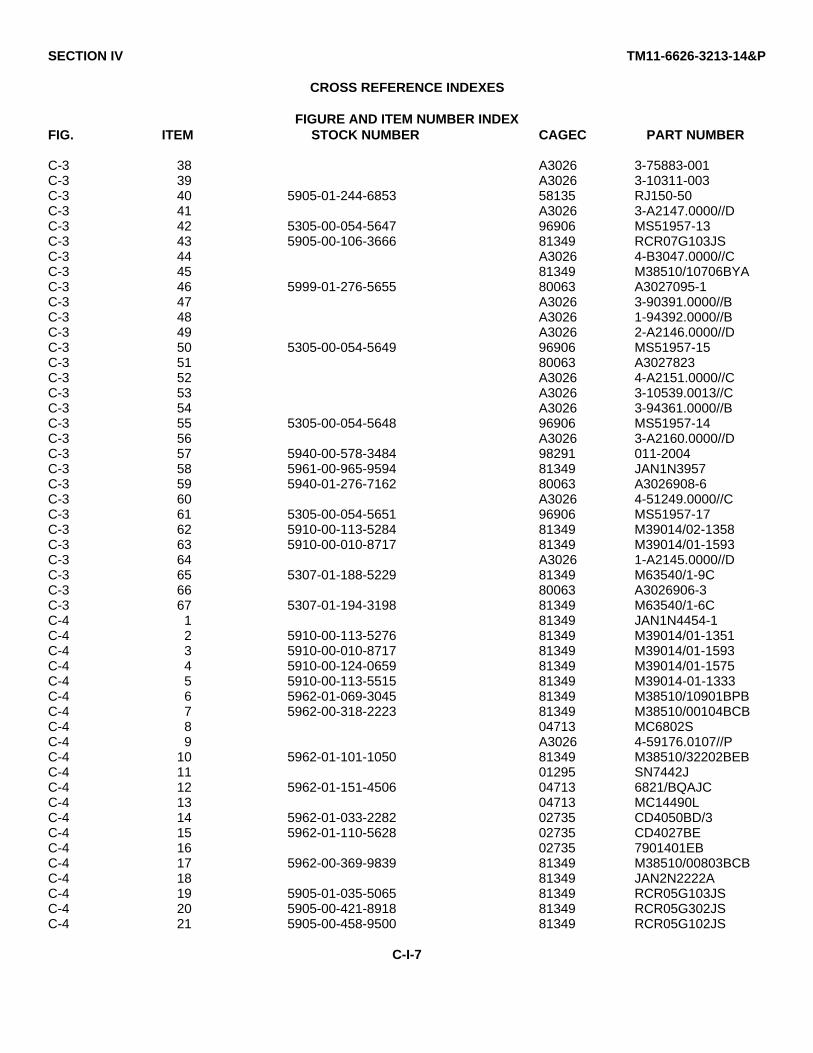
SECTION IV TM11-6626-3213-14&P
CROSS REFERENCE INDEXES
FIGURE AND ITEM NUMBER INDEXFIG. ITEM STOCK NUMBER CAGEC PART NUMBER
C-3 38 A3026 3-75883-001C-3 39 A3026 3-10311-003C-3 40 5905-01-244-6853 58135 RJ150-50C-3 41 A3026 3-A2147.0000//DC-3 42 5305-00-054-5647 96906 MS51957-13C-3 43 5905-00-106-3666 81349 RCR07G103JSC-3 44 A3026 4-B3047.0000//CC-3 45 81349 M38510/10706BYAC-3 46 5999-01-276-5655 80063 A3027095-1C-3 47 A3026 3-90391.0000//BC-3 48 A3026 1-94392.0000//BC-3 49 A3026 2-A2146.0000//DC-3 50 5305-00-054-5649 96906 MS51957-15C-3 51 80063 A3027823C-3 52 A3026 4-A2151.0000//CC-3 53 A3026 3-10539.0013//CC-3 54 A3026 3-94361.0000//BC-3 55 5305-00-054-5648 96906 MS51957-14C-3 56 A3026 3-A2160.0000//DC-3 57 5940-00-578-3484 98291 011-2004C-3 58 5961-00-965-9594 81349 JAN1N3957C-3 59 5940-01-276-7162 80063 A3026908-6C-3 60 A3026 4-51249.0000//CC-3 61 5305-00-054-5651 96906 MS51957-17C-3 62 5910-00-113-5284 81349 M39014/02-1358C-3 63 5910-00-010-8717 81349 M39014/01-1593C-3 64 A3026 1-A2145.0000//DC-3 65 5307-01-188-5229 81349 M63540/1-9CC-3 66 80063 A3026906-3C-3 67 5307-01-194-3198 81349 M63540/1-6CC-4 1 81349 JAN1N4454-1C-4 2 5910-00-113-5276 81349 M39014/01-1351C-4 3 5910-00-010-8717 81349 M39014/01-1593C-4 4 5910-00-124-0659 81349 M39014/01-1575C-4 5 5910-00-113-5515 81349 M39014-01-1333C-4 6 5962-01-069-3045 81349 M38510/10901BPBC-4 7 5962-00-318-2223 81349 M38510/00104BCBC-4 8 04713 MC6802SC-4 9 A3026 4-59176.0107//PC-4 10 5962-01-101-1050 81349 M38510/32202BEBC-4 11 01295 SN7442JC-4 12 5962-01-151-4506 04713 6821/BQAJCC-4 13 04713 MC14490LC-4 14 5962-01-033-2282 02735 CD4050BD/3C-4 15 5962-01-110-5628 02735 CD4027BEC-4 16 02735 7901401EBC-4 17 5962-00-369-9839 81349 M38510/00803BCBC-4 18 81349 JAN2N2222AC-4 19 5905-01-035-5065 81349 RCR05G103JSC-4 20 5905-00-421-8918 81349 RCR05G302JSC-4 21 5905-00-458-9500 81349 RCR05G102JS
C-I-7

SECTION IV TM11-6626-3213-14&P
CROSS REFERENCE INDEXES
FIGURE AND ITEM NUMBER INDEXFIG. ITEM STOCK NUMBER CAGEC PART NUMBER
C-4 22 5905-00-458-9347 81349 RCR05G124JSC-4 23 5905-00-177-7486 81349 RCR05G221JSC-4 24 5905-00-111-4738 81349 RCR20G152JSC-4 25 5905-00-195-4074 81349 RCR05G105JSC-4 26 5905-00-617-5091 81349 RCR05G472JSC-4 27 5905-00-458-9346 81349 RCR05G104JSC-4 28 5905-00-197-0224 81349 RCR05G511JSC-4 29 5905-00-413-1200 81349 RCR05G203JSC-4 30 80063 A3026810-1C-4 31 06726 ICN-406-S5-GC-4 32 06726 ICN-246-S4-GC-4 33 80063 A3034571-3C-4 34 A3026 4-A2151.0000//CC-4 35 58189 666273-074C-5 1 5910-00-010-8717 81349 M39014/01-1593C-5 2 81349 CLR65BB560KGLC-5 3 5910-01-100-8108 31433 T370-D106M020ASC-5 4 31433 T372B225M010ASC-5 5 31433 T372E336M006ASC-5 6 5910-00-143-0501 81349 M39014/02-1332C-5 7 5910-00-113-5284 81349 M39014/02-1358C-5 8 A3026 696017.180//KC-5 9 5962-01-195-1993 06481 971325-2102C-5 10 5962-01-164-8741 07933 RM3503ADC3C-5 11 5962-01-274-1575 55154 SL6270C-CMC-5 12 5962-01-033-2282 02735 CD4050BD/3C-5 13 5962-00-369-9839 81349 M38510/00803BCBC-5 14 5905-00-470-9481 81349 RCR05G202JSC-5 15 5905-01-161-7274 81349 RJR26FW503RC-5 16 5905-00-689-1290 81349 RCR05G512JSC-5 17 5905-00-195-4074 81349 RCR05G105JSC-5 18 5905-01-184-3510 81349 RJR26FW103RC-5 19 5905-01-035-5065 81349 RCR05G103JSC-5 20 5905-00-235-3534 81349 RCR32G681JSC-5 21 5950-01-078-6496 81349 M27/70-10C-5 22 5999-01-194-9729 81349 M38527/02-017DC-5 23 5999-01-080-1971 81349 M38527-1-18B1C-5 24 80063 A3034571-3C-5 25 A3026 4-A2151.0000//CC-5 26 58189 666273-074C-6 1 5910-00-166-6757 81349 M39014/01-1568C-6 2 5910-00-113-9448 81349 M39014/01-1354C-6 3 5910-00-098-9242 81349 M39014/01-1566C-6 4 81349 CKR05BX271KPC-6 5 5910-00-143-0501 81349 M39014/02-1332C-6 6 5950-00-031-4557 96906 MS75084-12C-6 7 5895-01-185-5408 80063 A3030174C-6 8 A3026 4-80886.0000//CC-6 9 A3026 4-B0887.0000//CC-6 10 A3026 4-B0890.0000//CC-6 11 58189 666273-074
C-I-8

SECTION IV TM11-6626-3213-14&P
CROSS REFERENCE INDEXES
FIGURE AND ITEM NUMBER INDEXFIG. ITEM STOCK NUMBER CAGEC PART NUMBER
C-7 1 5935-00-948-2792 71468 DD51217C-7 2 5999-00-021-2119 18876 9073891-3C-7 3 A3026 DDMY-43W25C-7 4 5935-00-402-1519 96214 531740-1C-7 5 71785 DM53740-5008C-7 6 5935-00-896-9910 18876 10125334-2C-8 1 71468 DB51213-1C-8 2 5935-00-489-9999 81349 M24308/4-3C-8 3 5935-00-905-2740 71468 DD51223-1
C-I-9

TM 11-6625-3213-14&P • ET900-AB-OMP-010/TS-4255-GRC215 • TO 33D7-13-108-1
GLOSSARY
Section I. ABBREVIATIONS AND ACRONYMS
AGC............................................................................................................................................... Automatic Gain ControlATU ....................................................................................................................................................Antenna Tuning Unit
BCD.................................................................................................................................................Binary Coded DecimalBITE.............................................................................................................................................. Built-In-Test EquipmentCCA................................................................................................................................................ Circuit Card AssemblyCMOS...........................................................................................................Complementary Metal Oxide SemiconductorCPU.............................................................................................................................................. Central Processing UnitCW ........................................................................................................................................................ Continuous Wave
dBm ................................................................................................................................. Decibels measured in milliwattsDMM....................................................................................................................................................... Digital Multimeter
ECCM.................................................................................................................... Electronic Counter-Counter MeasuresEIR............................................................................................................... Equipment Improvement RecommendationsEPROM ....................................................................................................... Erasable Programmable Read Only Memory
FH....................................................................................................................................................... Frequency HoppingFO..........................................................................................................................................................................Fold-Out
GND.........................................................................................................................................................................Ground
Hz .............................................................................................................................................................................. Hertz
IAW..................................................................................................................................................... In Accordance WithIC............................................................................................................................................................ Integrated CircuitIF .................................................................................................................................................. Intermediate Frequency
KHz........................................................................................................................................................................KilohertzKohms ....................................................................................................................................................................KilohmsLED......................................................................................................................................................Light-emitting DiodeLSB........................................................................................................................................................... Lower Sideband
MAC..................................................................................................................................... Maintenance Allocation ChartMDCS................................................................................................................ Maintenance Data Collection SubsystemMHz ................................................................................................................................................................... MegahertzMIL STD .................................................................................................................................................. Military StandardmSec .............................................................................................................................................................. millisecondsmV ....................................................................................................................................................................... milliVoltsMWO ........................................................................................................................................... Modification Work OrderNSN............................................................................................................................................... National Stock Number
GLOSSARY-1
TM 11-6625-3213-14&P • ET900-AB-OMP-010/TS-4255-GRC215 • TO 33D7-13-108-1
P/N.................................................................................................................................................................. Part NumberPA.............................................................................................................................................................. Power AmplifierPTT................................................................................................................................................................Push-To-Talk
R/E............................................................................................................................................................ Receiver/ExciterRF............................................................................................................................................................ Radio FrequencyROD................................................................................................................................................ Report of DiscrepancyRPSTL....................................................................................................................... Repair Parts and Special Tools ListRX.......................................................................................................................................................................... Receive
SRA ................................................................................................................................................ Special Repair Activity
TCL...................................................................................................................................................Tone Converter LogicTDR ............................................................................................................................ Transportation Discrepancy ReportTP....................................................................................................................................................................... Test PointTTL ...................................................................................................................................... Transistor to Transistor LogicTX......................................................................................................................................................................... Transmit
USB .......................................................................................................................................................... Upper SidebandUUT ...........................................................................................................................................................Unit-Under-Test
VCO.......................................................................................................................................Voltage Controlled OscillatorVDC..................................................................................................................................................... Volts Direct CurrentVSWR.................................................................................................................................. Voltage Standing Wave Ratio
W .................................................................................................................................................................................Watt
GLOSSARY-2

By Order of the Secretary of the Army:
CARL E. VUONOGeneral, United States Army
Chief of Staff
Official:
WILLIAM J. MEEHAN IIBrigadier General, United States Army
The Adjutant General
By Order of the Secretary of the Navy:JOHN C. WEAVER
Rear Admiral, United States NavyCommander, Space and Naval Warfare
Systems Command
By Order of the Secretary of the Air Force:LARRY D. WELSH
General, United States Air ForceChief of Staff
Official:
CHARLES C. McDONALDGeneral, United States Air Force
Commander, Air ForceLogistics Command
Distribution:
To be distributed in accordance with special list.
U.S. GOVERNMENT PRINTING OFFICE1990/712-094/20334

TM 11-6625-3213-14&P • ET900-AB-OMP-010/TS-4255-GRC215 • TO 33D7-29-80-1
Figure FO-1. SCHEMATIC DIAGRAM,
TS-4255/GRC-215

TM 11-6625-3213-14&P • ET900-AB-OMP-010/TS-4255-GRC215 • TO 33D7-29-80-1
Figure FO-2. PIN ASSIGNMENTS, CABLE ASSY W1, W67, and W68 .


PIN : 067625-0000