arm trustzone cryptocell-712 - csrc · this document is the non-proprietary security policy for...
TRANSCRIPT
Arm® TrustZone® CryptoCell-712Revision 1.19
FIPS 140-2 Non-Proprietary Security Policy
Non-confidential
Copyright © 2016, 2017, 2018, Arm® Limited or its affiliates. All rights reserved.

Copyrights and Trademarks
Copyright © 2016, 2017, 2018, Arm® Limited or its affiliates. All rights reserved.
This document can be reproduced and distributed only whole and intact, including this copyright notice.
Arm Limited. Company 02557590 registered in England.
110 Fulbourn Road, Cambridge, England CB1 9NJ.

Contents
Contents
List of Figures 1-6
List of Tables 1-6
1 Cryptographic Module Specification 1-71.1 Module integration . . . . . . . . . . . . . . . . . . . . . . . . . . . . . . . . . 1-71.2 TrustZone® architecture, TEE and REE . . . . . . . . . . . . . . . . . . . . . . 1-91.3 Approved security functions and mode of operation . . . . . . . . . . . . . . . . 1-9
1.3.1 Approved security functions . . . . . . . . . . . . . . . . . . . . . . . . 1-91.3.2 Allowed security functions . . . . . . . . . . . . . . . . . . . . . . . . . 1-121.3.3 Non-Approved security functions . . . . . . . . . . . . . . . . . . . . . 1-121.3.4 Approved security mode . . . . . . . . . . . . . . . . . . . . . . . . . . 1-13
1.4 Components and cryptographic boundary . . . . . . . . . . . . . . . . . . . . . 1-141.4.1 Components . . . . . . . . . . . . . . . . . . . . . . . . . . . . . . . . 1-14
1.4.1.1 Shared Hardware . . . . . . . . . . . . . . . . . . . . . . . . 1-151.4.1.1.1 Symmetric Cryptography Engine . . . . . . . . . . . 1-151.4.1.1.2 Hardware Key Slots . . . . . . . . . . . . . . . . . . 1-151.4.1.1.3 Inter-Core Connection . . . . . . . . . . . . . . . . 1-15
1.4.1.2 TEE Hardware . . . . . . . . . . . . . . . . . . . . . . . . . . 1-161.4.1.2.1 Asymmetric Cryptography Accelerator (PKA) . . . . 1-161.4.1.2.2 Non-Volatile Memory Manager . . . . . . . . . . . . 1-161.4.1.2.3 One-Time Programmable Memory (OTP) . . . . . . 1-161.4.1.2.4 True Random Number Generator (TRNG) . . . . . . 1-161.4.1.2.5 Persistent State Interface . . . . . . . . . . . . . . . 1-161.4.1.2.6 Secure Timer . . . . . . . . . . . . . . . . . . . . . 1-171.4.1.2.7 Dedicated SRAM . . . . . . . . . . . . . . . . . . . 1-17
1.4.1.3 REE Hardware . . . . . . . . . . . . . . . . . . . . . . . . . . 1-171.4.1.3.1 Dedicated SRAM . . . . . . . . . . . . . . . . . . . 1-17
1.4.1.4 TEE Firmware . . . . . . . . . . . . . . . . . . . . . . . . . . 1-171.4.1.4.1 ROM Library . . . . . . . . . . . . . . . . . . . . . 1-171.4.1.4.2 Cryptography Software (CRYS) . . . . . . . . . . . 1-171.4.1.4.3 Runtime Utility Functions . . . . . . . . . . . . . . 1-181.4.1.4.4 RAM Backup and Restore . . . . . . . . . . . . . . 1-181.4.1.4.5 Deterministic Random Bit Generator (DRBG) . . . . 1-181.4.1.4.6 Secure Boot . . . . . . . . . . . . . . . . . . . . . . 1-181.4.1.4.7 Secure Debug . . . . . . . . . . . . . . . . . . . . . 1-191.4.1.4.8 Abstraction layers . . . . . . . . . . . . . . . . . . . 1-19
1.4.1.5 REE Firmware . . . . . . . . . . . . . . . . . . . . . . . . . . 1-201.4.1.5.1 IV Generator . . . . . . . . . . . . . . . . . . . . . 1-20
1.4.2 Cryptographic boundary . . . . . . . . . . . . . . . . . . . . . . . . . . 2-21
2 Ports and Interfaces 2-222.1 TEE and REE Hardware Interfaces . . . . . . . . . . . . . . . . . . . . . . . . . 2-22
2.1.1 APB Slave . . . . . . . . . . . . . . . . . . . . . . . . . . . . . . . . . 2-222.1.2 Interrupt . . . . . . . . . . . . . . . . . . . . . . . . . . . . . . . . . . . 2-22
Copyright © 2016, 2017, 2018, Arm® Limited or its affiliates. All rights reserved. 3

Contents
2.2 Shared Hardware Interfaces . . . . . . . . . . . . . . . . . . . . . . . . . . . . . 2-222.2.1 AXI Master . . . . . . . . . . . . . . . . . . . . . . . . . . . . . . . . . 2-222.2.2 Clocks . . . . . . . . . . . . . . . . . . . . . . . . . . . . . . . . . . . 2-232.2.3 Power . . . . . . . . . . . . . . . . . . . . . . . . . . . . . . . . . . . . 2-232.2.4 Reset . . . . . . . . . . . . . . . . . . . . . . . . . . . . . . . . . . . . 2-232.2.5 Scan Interface . . . . . . . . . . . . . . . . . . . . . . . . . . . . . . . . 2-23
2.3 TEE Firmware . . . . . . . . . . . . . . . . . . . . . . . . . . . . . . . . . . . 2-232.4 REE Firmware . . . . . . . . . . . . . . . . . . . . . . . . . . . . . . . . . . . 2-23
2.4.1 Linux Kernel Driver services . . . . . . . . . . . . . . . . . . . . . . . . 2-232.4.2 Status service . . . . . . . . . . . . . . . . . . . . . . . . . . . . . . . . 3-24
3 Roles, Services and Authentication 3-253.1 Roles . . . . . . . . . . . . . . . . . . . . . . . . . . . . . . . . . . . . . . . . 3-253.2 Services . . . . . . . . . . . . . . . . . . . . . . . . . . . . . . . . . . . . . . . 3-253.3 Authentication . . . . . . . . . . . . . . . . . . . . . . . . . . . . . . . . . . . . 4-31
4 Finite State Model 4-324.1 Deployed states . . . . . . . . . . . . . . . . . . . . . . . . . . . . . . . . . . . 4-324.2 Manufacturing and recovery states . . . . . . . . . . . . . . . . . . . . . . . . . 4-32
5 Physical Security 6-34
6 Operational Environment 7-35
7 Cryptographic Key Management 7-367.1 User Keys . . . . . . . . . . . . . . . . . . . . . . . . . . . . . . . . . . . . . . 7-377.2 Platform Keys . . . . . . . . . . . . . . . . . . . . . . . . . . . . . . . . . . . . 7-37
7.2.1 Blocking access to Platform Keys . . . . . . . . . . . . . . . . . . . . . 7-377.3 Key generation . . . . . . . . . . . . . . . . . . . . . . . . . . . . . . . . . . . 7-387.4 Key establishment . . . . . . . . . . . . . . . . . . . . . . . . . . . . . . . . . . 7-387.5 Key entry and output . . . . . . . . . . . . . . . . . . . . . . . . . . . . . . . . 8-397.6 Key storage . . . . . . . . . . . . . . . . . . . . . . . . . . . . . . . . . . . . . 8-397.7 Key zeroization . . . . . . . . . . . . . . . . . . . . . . . . . . . . . . . . . . . 8-39
8 Electromagnetic Interference / Compatibility (EMI/EMC) 9-40
9 Self Tests 9-419.1 Power-up tests . . . . . . . . . . . . . . . . . . . . . . . . . . . . . . . . . . . . 9-41
9.1.1 Cryptography test . . . . . . . . . . . . . . . . . . . . . . . . . . . . . . 9-419.1.1.1 Tests repeated in both TEE and REE . . . . . . . . . . . . . . 9-419.1.1.2 Tests in REE . . . . . . . . . . . . . . . . . . . . . . . . . . . 9-419.1.1.3 Tests in the TEE . . . . . . . . . . . . . . . . . . . . . . . . . 9-41
9.1.2 Firmware integrity test . . . . . . . . . . . . . . . . . . . . . . . . . . . 10-429.2 Conditional tests . . . . . . . . . . . . . . . . . . . . . . . . . . . . . . . . . . 10-42
10 Design Assurance 11-4310.1 Guidance . . . . . . . . . . . . . . . . . . . . . . . . . . . . . . . . . . . . . . 11-43
10.1.1 Operator guidance . . . . . . . . . . . . . . . . . . . . . . . . . . . . . 11-4310.2 Proprietary documentation . . . . . . . . . . . . . . . . . . . . . . . . . . . . . 11-43
Copyright © 2016, 2017, 2018, Arm® Limited or its affiliates. All rights reserved. 4

Contents
11 Mitigation of Other Attacks 11-44
Glossary 45
References 46
Copyright © 2016, 2017, 2018, Arm® Limited or its affiliates. All rights reserved. 5

List of Figures
List of Figures
1 Arm® Juno rev.2 board - hardware architecture . . . . . . . . . . . . . . . . . . 1-82 LogicTile FPGA board front . . . . . . . . . . . . . . . . . . . . . . . . . . . . 1-83 LogicTile FPGA board back . . . . . . . . . . . . . . . . . . . . . . . . . . . . 1-94 CryptoCell-712 high level diagram . . . . . . . . . . . . . . . . . . . . . . . . . 1-105 CryptoCell-712 hardware diagram . . . . . . . . . . . . . . . . . . . . . . . . . 1-146 TEE firmware components . . . . . . . . . . . . . . . . . . . . . . . . . . . . . 1-187 REE firmware components . . . . . . . . . . . . . . . . . . . . . . . . . . . . . 1-20
List of Tables
1 Security levels . . . . . . . . . . . . . . . . . . . . . . . . . . . . . . . . . . . . 1-72 Approved security functions . . . . . . . . . . . . . . . . . . . . . . . . . . . . 1-113 Allowed security functions . . . . . . . . . . . . . . . . . . . . . . . . . . . . . 1-124 Non-Approved security functions . . . . . . . . . . . . . . . . . . . . . . . . . . 1-135 Ports and interfaces . . . . . . . . . . . . . . . . . . . . . . . . . . . . . . . . . 2-226 Services . . . . . . . . . . . . . . . . . . . . . . . . . . . . . . . . . . . . . . . 3-267 Module keys and CSPs . . . . . . . . . . . . . . . . . . . . . . . . . . . . . . . 7-368 User key sizes . . . . . . . . . . . . . . . . . . . . . . . . . . . . . . . . . . . . 7-379 Blocking access to platform keys . . . . . . . . . . . . . . . . . . . . . . . . . . 7-38
Copyright © 2016, 2017, 2018, Arm® Limited or its affiliates. All rights reserved. 1-6

Cryptographic Module Specification
1 Cryptographic Module Specification
This document is the non-proprietary security policy for Arm® TrustZone® CryptoCell-712.This security policy describes how CryptoCell-712 meets the security requirements of FIPS140-2, and how to operate CryptoCell-712 securely, in a FIPS-compliant manner. This policy issubmitted as part of the Federal Information Processing Standard (FIPS) 140-2 Level 1 validationprocess of CryptoCell-712. For more information about the Cryptographic Module ValidationProgram (CMVP), see: http://csrc.nist.gov/groups/STM/cmvp/.
CryptoCell-712 is a security engine with a root of trust and cryptographic acceleratorcapabilities. It is intended for use in an SOC (System on Chip), where it provides foundationalsecurity services for the entire platform, including cryptography, key management, platformidentity, secure boot, secure Life Cycle State (LCS), and secure debug. It offers high-throughputcryptography engines suitable for a diverse set of use cases, such as secure playback of DRM(Digital Rights Management) protected media content, IPsec VPNs, TLS/SSL link protection,drive encryption and more.
Under the FIPS 140-2 definitions, the CryptoCell-712 is a firmware-hybrid module anda sub-chip module. The module includes hardware, defined in the RTL (Register TransferLanguage), and firmware for execution on the host CPU, making it a hybrid module. Themodule’s RTL is offered for integration as part of a silicon partner’s (customer’s) hardware host— an SOC, containing the cryptographic module’s hardware alongside the Host CPU, memoriesand peripherals, making it a sub-chip component.
The following table depicts the security level claimed for each of the eleven sections thatcomprise the FIPS 140-2:
Table 1: Security levels
FIPS 140-2 Sections Security Level1 Cryptographic Module Specification 12 Cryptographic Module Ports and Interfaces 13 Roles, Services and Authentication 14 Finite State Model 15 Physical Security 16 Operational Environment N/A7 Cryptographic Key Management 18 EMI/EMC 19 Self-Tests 110 Design Assurance 111 Mitigation of Other Attacks N/A
1.1 Module integration
CryptoCell-712 is primarily intended for integration as an IP (Intellectual Property) block intoa partner’s silicon product. The module is provided to partners as Silicon IP and accompanyingfirmware. The partner integrates the silicon with the host CPU hardware, and installs thefirmware into the host NVRAM (Non Volatile Random Access Memory).
For the purposes of this Cryptographic Module Validation the module was tested on theexpanded Arm® Juno rev.2 in a configuration reflecting partner’s hosting SoC implementation.The expanded board contains compute subsystem running the operating firmware connected tothe LogicTile FPGA (Field Programmable Gate Array) expansion with the synthesized hardware.
Copyright © 2016, 2017, 2018, Arm® Limited or its affiliates. All rights reserved. 1-7

Cryptographic Module Specification
For ease of notation it shall be referred throughout the document as Arm® Juno board. Insteadof the partner’s applications, Arm® provides test software used to invoke the module’s services.The FPGA board does not have some properties of a real silicon product, most importantly OTP(One-Time Programmable memory) which is only simulated (see Section 1.4.1.2.3).
Figure 1: Arm® Juno rev.2 board - hardware architecture
The implementation of the module is located on the LogicTile FPGA expansion as presentedin Figure 1.
Figure 2: LogicTile FPGA board front
Copyright © 2016, 2017, 2018, Arm® Limited or its affiliates. All rights reserved. 1-8

Cryptographic Module Specification
Figure 3: LogicTile FPGA board back
1.2 TrustZone® architecture, TEE and REE
CryptoCell-712 is intended for use in an Arm® TrustZone® platform, where a single Arm® Hostprocessor runs two separate environments: a TEE (Trusted Execution Environment), and a REE(Rich Execution Environment). The TrustZone® architecture uses a single CPU to run both theTEE and the REE, with dedicated hardware enforcing the separation between control states, dataand memories belonging to the different components.
The firmware in the TEE is generally compact and strictly controlled by the manufacturer,and is typically dedicated to providing security services to applications in REE. The firmware inthe REE consists of an OS (Operating System) kernel, controlled by the manufacturer, and anapplication layer, typically modifiable by the user. The host OS for this certification is Linux OSkernel version 3.18. The module is compatible with multiple Linux variants including Android.
The version numbers for this certification are:
• Hardware 712• TEE firmware 1.1.0.48• TEE secure boot ROM 1.0.0.1145• REE firmware 1.1.0.49
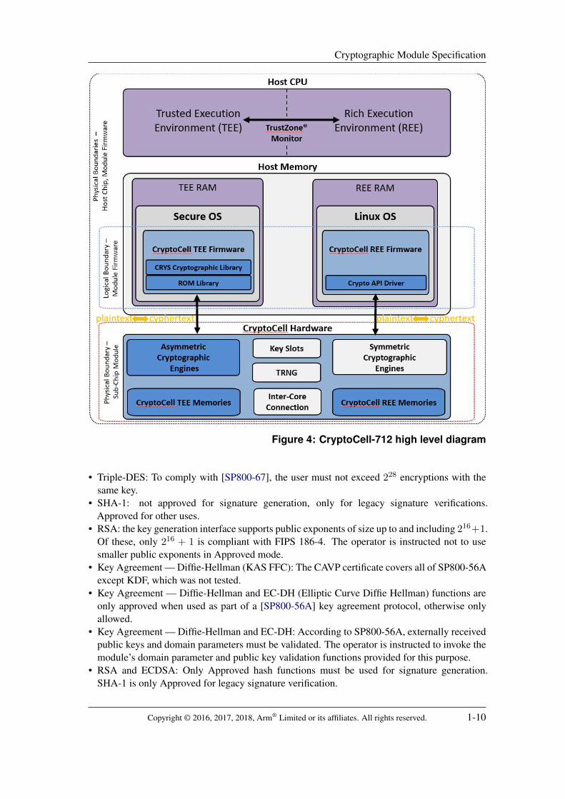
The CryptoCell-712 hardware has some dedicated TEE and REE components, providingfunctionality to the corresponding host environment, and some shared components, includingthe Symmetric Cryptography Engine. The shared engine alternates between TEE and REE states,with hardware enforcement of data and memory separation similar to that of the host CPU. Othershared components communicate between the TEE and REE. A high level diagram of the moduleis shown in Figure 4.
1.3 Approved security functions and mode of operation
1.3.1 Approved security functions
CryptoCell-712 supports FIPS-approved security functions, as specified in Table 2. Thefollowing notes and caveats apply:
Copyright © 2016, 2017, 2018, Arm® Limited or its affiliates. All rights reserved. 1-9
Cryptographic Module Specification
Figure 4: CryptoCell-712 high level diagram
• Triple-DES: To comply with [SP800-67], the user must not exceed 228 encryptions with thesame key.
• SHA-1: not approved for signature generation, only for legacy signature verifications.Approved for other uses.
• RSA: the key generation interface supports public exponents of size up to and including 216+1.Of these, only 216 + 1 is compliant with FIPS 186-4. The operator is instructed not to usesmaller public exponents in Approved mode.
• Key Agreement — Diffie-Hellman (KAS FFC): The CAVP certificate covers all of SP800-56Aexcept KDF, which was not tested.
• Key Agreement — Diffie-Hellman and EC-DH (Elliptic Curve Diffie Hellman) functions areonly approved when used as part of a [SP800-56A] key agreement protocol, otherwise onlyallowed.
• Key Agreement — Diffie-Hellman and EC-DH: According to SP800-56A, externally receivedpublic keys and domain parameters must be validated. The operator is instructed to invoke themodule’s domain parameter and public key validation functions provided for this purpose.
• RSA and ECDSA: Only Approved hash functions must be used for signature generation.SHA-1 is only Approved for legacy signature verification.
Copyright © 2016, 2017, 2018, Arm® Limited or its affiliates. All rights reserved. 1-10

Cryptographic Module Specification
Table 2: Approved security functions
CAVP Cert Algorithm StandardMode /Method
Key Lengths,Curves orModuli
Use
RE
E
TE
E
REE: #4743TEE: #4749
AES[FIPS-197,SP800-38A,SP800-38E]
ECB, CBC, OFB,CTR, XTS-AES
128, 192, 256,512 (XTS)
Encryption /decryption
3 3
Vendor-affirmed
AES [SP800-38Aadd] CBC-CS1 128, 192, 256Encryption /decryption
3 3
REE: #4743TEE: #4749
AES [SP800-38C] CCM 128, 192, 256Authenticatedencryption /decryption
3 3
REE: #4743TEE: #4749
AES [SP800-38B] CMAC 128, 192, 256Messageauthentication
3 3
REE: #2522TEE: #2523
Triple-DES[FIPS-46-3,SP800-67]
ECB, CBC 192Encryption /decryption
3 3
REE: #3887TEE: #3892
SHS [FIPS-180-4]SHA-1, SHA-224,SHA-256, SHA-384,SHA-512
Messageauthentication
3 3
REE: #3158TEE: #3163
HMAC[FIPS-198-1,RFC2104]
HMAC SHA-1,SHA-224, SHA-256,SHA-384, SHA-512
Messageauthentication
3 3
#4743 AES[JEDEC, 6.3.4,9.4] [FIPS-197,SP800-38A]
CBC for ESSIV 128, 256Encryption /decryption
3
#4743 AES[JEDEC, 6.3.2,9.2] [FIPS-197,SP800-38A]
CBC for BitLocker 128, 256Encryption /decryption
3
#2593 RSA [FIPS-186-4]SHA functionsPSS, PKCS1-v1.5
2048, 3072
SignatureGeneration /Verification /Key Generation
3
#2596RSA (FirmwareCertificate Verification)
[FIPS-186-4] PSS; SHA-256 2048SignatureVerification
3
#1385 CVL (KAS FFC) [SP800-56A] FFC(2048, 224),(2048, 256)
Shared SecretComputation
3
#1385 CVL (ECC CDH) [SP800-56A] ECCP-224, P-256,P-384, P-521
ECC CDHPrimitive
3
#1184ECDSA (Elliptic CurveDigital SignatureScheme)
[FIPS-186-4] SHA functionsP-224, P-256,P-384, P-521
SignatureGeneration /Verification /Key PairGeneration /Public KeyValidation
3
#151KBKDF (Key BasedKey DerivationFunction)
[SP800-108] Counter modeCMAC AES-128,256
Key derivation 3
#1386 CVL (ANS 9.63)[SP800-135,ANSI-X9.63]
Section 5.1, ANSX9.63-2001
Key derivation 3
#1630DRBG (DeterministicRandom Bit Generator)
[SP800-90A] CTR-DRBG 256Random BitGeneration
3
Vendor-affirmed
CKG [SP800-133]Input toasymmetrickey generation
3
Copyright © 2016, 2017, 2018, Arm® Limited or its affiliates. All rights reserved. 1-11

Cryptographic Module Specification
• ESSIV: AES-CBC algortihm with proprietary method for IV generation. The encryption keyis different from the key used in the IV generation operation. Both keys are same size, either128 or 256 bit.
• Bitlocker: AES-CBC algortihm with proprietary method for IV generation. The encryptionkey is different from the key used in the IV generation operation. Both keys are same size,either 128 or 256 bit.
1.3.2 Allowed security functions
CryptoCell-712 TEE also supports several FIPS-allowed security functions, as specified inTable 3.
Table 3: Allowed security functions
Algorithm Caveat UseTrue Random Number Generator[NDRNG]
There is no NIST-approvedstandard for NDRNG
DRBG seeding and reseeding
RSAES-OAEP [PKCS1]Moduli: 2048, 3072
NIST allows RSA encryption forkey wrapping only, but does notapprove itKey establishment strength 112 or128 bits
Encryption/decryption
RSAES-PKCS1-v1 5 [PKCS1]Moduli: 2048, 3072
NIST allows RSA encryption forkey wrapping only, but does notapprove itKey establishment strength 112 or128 bits
Encryption/decryption
Diffie-Hellman [SP800-56A]Key establishment strength 112bits
Key agreement
EC Diffie-Hellman [SP800-56A]Curves: p224k1, p256k1
Key establishment strength 112 or128 bits
Key agreement
ECDSA (Elliptic Curve DigitalSignature Scheme)Curves: p224k1, p256k1
NIST allows non-NISTrecommended curves of at least112 bit security strength
Signature Generation /Verification /Key Pair Generation /Public Key Validation
The following notes and caveats apply:
• NIST allows RSA encryption/decryption for key wrapping only. Key establishment strength112 or 128 bits.
1.3.3 Non-Approved security functions
CryptoCell-712 also supports non-FIPS-approved security functions and modes, as specified inTable 4. The following notes and caveats apply:
• IVGEN RNG: see Section 1.4.1.5.1.• Triple-DES: Supports 2-key bundles, which is no longer approved as of 2016. Enforces distinct
keys. Rejects DES weak keys.• The ECIES relies on CAVP validated components, as it consists of a key agreement step
conforming to [SP800-56A] followed by a key derivation step conforming to [PKCS1]or [ANSI-X9.63]. Nevertheless the scheme itself is not FIPS-approved.
Copyright © 2016, 2017, 2018, Arm® Limited or its affiliates. All rights reserved. 1-12

Cryptographic Module Specification
Table 4: Non-Approved security functions
Algorithm UseR
EE
TE
E
AES non-approved modes — CBC-MAC [ISO/IEC-9797-1:2011] Message authentication 3
AES non-approved modes — XCBC-MAC [RFC3566] Message authentication 3 3
AES GCM and GMAC [SP800-38D]Encryption/decryptionMessage authentication
3
DES ECB, CBC [FIPS-46-3] Encryption/decryption 3 3
Triple-DES ECB, CDC with 2-key bundles [FIPS-46-3, SP800-67] Encryption/decryption 3 3
MD5 [RFC1321] Message authentication 3 3
HMAC-MD5 [FIPS-198-1, RFC2104] Message authentication 3 3
IVGEN RNG (Random Number Generator) IV generation 3
ECIES (Elliptic Curve Integrated Encryption Scheme) [IEEE1363]Curves: p160k1, p160r1, p160r2, p192k1, p224k1, p256k1, P-192,P-224, P-256, P-384, P-521
Key agreement 3
KDF1 and KDF2 Key Derivation Functions [ISO/IEC-18033-2] Key derivation 3
ECC key generation with Non-Approved sizes [FIPS-186-4]Curves: p160k1, p160r1, p160r2, p192k1, P-192
Key generation 3
ECDSA with Non-Approved sizes [FIPS-186-4]Curves: p160k1, p160r1, p160r2, p192k1, P-192
Signature generation /verification
3
KAS EC-DH key agreement [SP800-56A]Curves: p160k1, p160r1, p160r2, p192k1, P-192
Key agreement 3
KAS DH (Diffie-Hellman) with Non-Approved sizes [SP800-56A]1024 bits
Key generationKey agreement
3
RSA with Non-Approved sizes [FIPS-186-4]1024, 4096 bits
Key generationSignature generation /verification
3
1.3.4 Approved security mode
The cryptographic module supports a single Approved mode of operation. On power-on, themodule performs power-on self-tests as described in Section 9. On failure, the module enters theError state; on success, the user chooses the mode of operation (Approved or Non-Approved) bypassing a boolean parameter to the firmware initialization routine. The FipsGetState API canbe used to check the mode at runtime, and returns Approved, Non-Approved, or Error state; thisAPI is implemented in both the TEE the REE.
In the Approved mode, all approved security functions listed in Section 1.3.1 are available.The non-approved security functions listed in Section 1.3.3 can be accessed but are disallowed bypolicy. There is no enforcement mechanism in place, therefore it is the user’s responsibility not touse the non-approved functions and services. In order to call any non-approved security functionsand services (listed as Non-Approved in the service table), the user is instructed to perform acold power-on and initialize the module in Non-Approved mode. All Approved services remainavailable in Non-Approved mode, and calling any Approved service temporarily puts the moduleinto Approved mode with the exception of RSA Key Generation and ECC Key Generation (theseservices omit conditional tests in Non-Approved mode). It is the user’s responsibility to avoidsharing user keys between the modes.
The user can only switch between Approved and Non-Approved mode through a power-onreset. All CSPs (Critical Security Parameters) stored in the module’s registers are cleared onpower-on reset. In the Approved mode, conditional tests are performed as described in Section 9.
Copyright © 2016, 2017, 2018, Arm® Limited or its affiliates. All rights reserved. 1-13
Cryptographic Module Specification
1.4 Components and cryptographic boundary
1.4.1 Components
TEE registers
TEE Descriptor
Queue
Host CPU Host Memory
System Bus
Physical Boundary – Host Chip
APB4 Slave
Clock
Reset
Scan
Physical Boundary – Sub-Chip Module
ARM TrustZoneCryptoCell 712
TEE APB4 Slave Interface TEE Interrupt REE APB4 Slave Interface REE Interrupt
Debug Control Unit
Life Cycle State
Secure Timer
Secure State Counter
Session Key
Persistent StateInterface
REE registers
REE Descriptor
Queue
APB4 Slave
Key Slots
AXI Master
Symmetric Cryptography Engines
AESAESMAC
HASH DESDescriptors Manager
SRAM Arbitrator
AXI Master Interface
DMA
TEE SRAM
Asymmetric Cryptography Engines
PKA EnginePKA
SRAMREE SRAM
AIB Interface
NVM Manager
OTP / NVRAM
TRNG
Customer Key
Platform Key
Inter-Core Connection
Figure 5: CryptoCell-712 hardware diagram
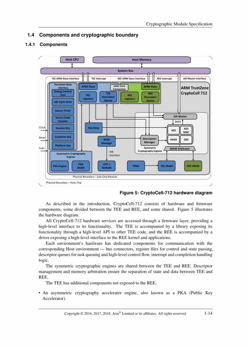
As described in the introduction, CryptoCell-712 consists of hardware and firmwarecomponents, some divided between the TEE and REE, and some shared. Figure 5 illustratesthe hardware diagram.
All CryptoCell-712 hardware services are accessed through a firmware layer, providing ahigh-level interface to its functionality. The TEE is accompanied by a library exposing itsfunctionality through a high-level API to other TEE code, and the REE is accompanied by adriver exposing a high-level interface to the REE kernel and applications.
Each environment’s hardware has dedicated components for communication with thecorresponding Host environment — bus connectors, register files for control and state passing,descriptor queues for task queuing and high-level control flow, interrupt and completion handlinglogic.
The symmetric cryptographic engines are shared between the TEE and REE. Descriptormanagement and memory arbitration ensure the separation of state and data between TEE andREE.
The TEE has additional components not exposed to the REE.
• An asymmetric cryptography accelerator engine, also known as a PKA (Public KeyAccelerator).
Copyright © 2016, 2017, 2018, Arm® Limited or its affiliates. All rights reserved. 1-14

Cryptographic Module Specification
• A TRNG (True Random Number Generator).• A non-volatile memory manager in charge of OTP storage and LCS (Life Cycle State)
management.• A DRBG implemented in firmware.• Additional security functions.
This section documents the major functional system components; for port and interfacecomponents responsible for carrying state and data signals to and from the host system, seeSection 2.
1.4.1.1 Shared Hardware
1.4.1.1.1 Symmetric Cryptography Engine The symmetric cryptography engine consists of thefollowing components:
• Cryptographic cores (AES encryption, AES message authentication, DES, MD5 and SHA hashfunctions, HMAC).
• A descriptor queue manager. The descriptor queue manager is responsible for high-levelcontrol flow, and allows firmware running on the Host CPU to queue multiple operations forprocessing by the cryptographic engines. An arbitrator ensures the correct descriptor queue isused in the each context — TEE and REE.
• Input and output DMA (Direct Memory Access) blocks. The DMA blocks allow input andoutput from host RAM (Random Access Memory) to dedicated TEE and REE SRAM (StaticRandom Access Memory) blocks.
The module provides hardware isolation for handling of platform keys. The AES cipher candirectly load platform keys without exposing them to the SRAM or the Host CPU. The results ofsome operations on platform keys are limited to loading directly into designated hardware keyregisters, allowing secure key derivation.
When in the REE context, the symmetric cryptography engine can also use symmetric AESkeys loaded into key slots (Section 1.4.1.1.2).
1.4.1.1.2 Hardware Key Slots Hardware key slots are dedicated hardware registers which let TEEsecurely create symmetric keys for REE to use. The module offers a TEE service to set the keyslot values, and the REE can specify a key slot (by index) when invoking AES services. Thoseare the only ways to access key slots; neither environment can read key slots, and the TEE itselfcannot use them for encryption.
The module defines 4 HW (Hardware) key slots for use by REE AES services. The slots beused as individual keys of size 128, 192, 256 bits or as double keys of 2∗128 or 2∗256 bits. Inthe latter case, two slots are used in each invocation. This functionality serves AES XTS, ESSIVand BitLocker modes.
1.4.1.1.3 Inter-Core Connection Since the module’s TEE and REE components of the modulehave separate state and memories, CryptoCell-712 contains a dedicated mechanism for passingmessages between the environments (here, referred to as cores). Consisting of a registerand an interrupt signal, the mechanism allows each core to notify the other and pass basicinformation. This mechanism is used to synchronize the FIPS 140-2 state (Self-Test, Approved,Non-Approved, Error and error code if any) between TEE and REE.
Copyright © 2016, 2017, 2018, Arm® Limited or its affiliates. All rights reserved. 1-15

Cryptographic Module Specification
1.4.1.2 TEE Hardware
1.4.1.2.1 Asymmetric Cryptography Accelerator (PKA) The Asymmetric CryptographyAccelerator or PKA (Public Key Accelerator) block operates as a large integer arithmetic logicunit. It supports all mathematical and logical operations required for implementing public-keycryptosystems based on the discrete-logarithm problem, the integer factorization problem, andthe prime-field elliptic-curve discrete logarithm problem.
1.4.1.2.2 Non-Volatile Memory Manager The Non-Volatile Memory (NVM) Manager uses aninternal, point-to-point Intel AIB (Intel Asynchronous Interface Bus Specification) interfaceto access a bank of OTP memory. For the contents of OTP memory, see Section 1.4.1.2.3.The NVM Manager processes the compactly-stored data in the OTP memory, and provides ahigh-level interface for the rest of the module.
Several CSPs such as platform keys and their hash values are stored in the OTP memory(see Section 7.2). The NVM Manager controls all access to these CSPs, protecting againstunauthorized reading and modification.
1.4.1.2.3 One-Time Programmable Memory (OTP) The module is meant to use OTP to providesome security features. When synthesized in a partner’s system-on-chip, the module uses anon-chip OTP bank based on eFuse or similar technology, depending on the manufacturer.
The FPGA board used for this validation can only simulate the write-once properties of realsilicon OTP. Instead, the FPGA’s Flash-based file system uses access permissions, allowing onlyadministrative users to overwrite the contents of the file system. This enables behaviors notpossible in the real silicon module, such as returning the module to normal operation from aterminal state. This functionality is used for FIPS 140-2 testing.
OTP bits can be written but cannot be erased, which has useful security properties. The OTPstores a counter of zero-bits alongside fields intended to be written exactly once, so that anymodification to the field or its zero-bit counter invalidates them. This protection method is usedto store non-modifiable values, such as keys and key hashes. The OTP also stores modifiablebut monotonically changing fields: firmware version counters and LCS bitmaps. Any changes tothose are made non-reversible by the properties of the OTP.
The OTP is used by the TEE to store data and control inputs used for various platformsecurity functions, including platform keys and their hash values (Section 7.2), LCS, andTRNG configuration. The OTP memory is initialized at manufacturing time, and from thatpoint on is hardware-limited to exclusive access through the Non-Volatile Memory Manager(Section 1.4.1.2.2).
1.4.1.2.4 True Random Number Generator (TRNG) The TEE contains a TRNG, which cannotbe accessed directly as a service, but can only be used as a source of entropy for seeding theDRBG of Section 1.4.1.4.5. The TRNG collects noise directly from hardware circuits withoutHost interaction, by sampling the output of a fast free-running ring oscillator.
1.4.1.2.5 Persistent State Interface The Persistent State Interface stores some of the TEE statein the always-on power domain, which survives a warm reset or module sleep (see Section 2.2.3)but not cold power-on. In the module submitted for validation, this is an internal component;however, a host platform can add logic to consume its signals as inputs for other componentsinside the host’s boundary. The Persistent State Interface is shown in Figure 5.
Copyright © 2016, 2017, 2018, Arm® Limited or its affiliates. All rights reserved. 1-16

Cryptographic Module Specification
The Persistent State Interface contains the following components:
• LCS (Life Cycle State), as defined in Section 4. Firmware components access the LCS througha dedicated firmware service.
• The DCU (Debug Control Unit) register, driven by the Secure Debug mechanism(Section 1.4.1.4.7). A host platform can use it to control its hardware debug capabilities.
• State Counter: a 32-bit counter, used by the RAM Backup and Restore service(Section 1.4.1.4.4).
• The Session Key KSESS , used by the RAM Backup and Restore service (Section 1.4.1.4.4).• Secure Timer: see Section 1.4.1.2.6. Firmware components access the Secure Timer through
a dedicated firmware service.
1.4.1.2.6 Secure Timer The TEE offers a secure timer, accessible through a firmware service.
1.4.1.2.7 Dedicated SRAM TEE has a block of dedicated SRAM (Static Random Access Memory).This is primarily used by the PKA, the symmetric cryptography engines, and the TRNG entropycollector.
The section of SRAM used by the PKA is cleared on completion of every operation. It isadditionally cleared on boot, in the Deployed and RMA (Return Merchandising Authorization)Life Cycle States (see Section 4). This ensures that any Security Critical Parameters andintermediate values used in computations do not pass between different Life Cycle States anddifferent roles.
1.4.1.3 REE Hardware
1.4.1.3.1 Dedicated SRAM REE has a block dedicated SRAM (Static Random Access Memory)for its descriptor queue and other needs. The descriptor queue size is configurable by partnersfor improved performance or reduced size.
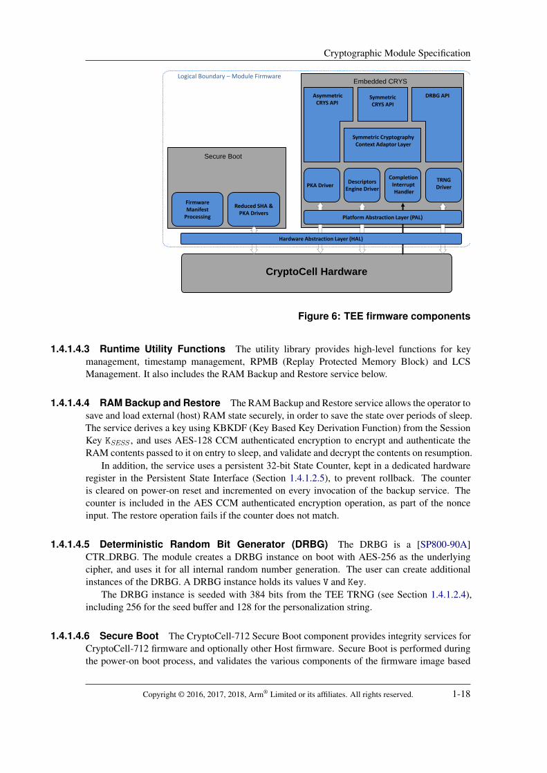
1.4.1.4 TEE Firmware Figure 6 depicts the firmware components associated with the TEE.These are divided between the Secure Boot ROM (Read-Only Memory) library, the CRYS(Cryptographic Software Library), various runtime utility components, and the Hardware andPlatform abstraction layers. The different functional components are described in detail below.
1.4.1.4.1 ROM Library The ROM library provides critical security functions used during theinitialization stages of the module and the host platform, including Secure Boot and SecureDebug certificate verification functionality. For the purposes of this validation, the library isimplemented in a read-only file system rather than an actual ROM, but partners can choose anunmodifiable ROM implementation to improve trust in the initialization process.
1.4.1.4.2 Cryptography Software (CRYS) The major TEE firmware component is the CRYS(Cryptographic Software Library), which in this module is implemented in firmware but mayhave software implementations. It offers cryptography functions which drive the module’shardware cryptography engines, and perform additional operations in firmware where needed.The CRYS APIs provide access to the symmetric and asymmetric cryptography enginesdescribed above in the hardware section, and the DRBG (Section 1.4.1.4.5).
Copyright © 2016, 2017, 2018, Arm® Limited or its affiliates. All rights reserved. 1-17
Cryptographic Module Specification
Secure Boot
Reduced SHA & PKA Drivers
Embedded CRYS
PKA DriverDescriptors
Engine Driver
Completion Interrupt Handler
TRNGDriver
Symmetric CryptographyContext Adaptor Layer
AsymmetricCRYS API
DRBG APISymmetricCRYS API
CryptoCell Hardware
Platform Abstraction Layer (PAL)
Hardware Abstraction Layer (HAL)
FirmwareManifest
Processing
Logical Boundary – Module Firmware
Figure 6: TEE firmware components
1.4.1.4.3 Runtime Utility Functions The utility library provides high-level functions for keymanagement, timestamp management, RPMB (Replay Protected Memory Block) and LCSManagement. It also includes the RAM Backup and Restore service below.
1.4.1.4.4 RAM Backup and Restore The RAM Backup and Restore service allows the operator tosave and load external (host) RAM state securely, in order to save the state over periods of sleep.The service derives a key using KBKDF (Key Based Key Derivation Function) from the SessionKey KSESS , and uses AES-128 CCM authenticated encryption to encrypt and authenticate theRAM contents passed to it on entry to sleep, and validate and decrypt the contents on resumption.
In addition, the service uses a persistent 32-bit State Counter, kept in a dedicated hardwareregister in the Persistent State Interface (Section 1.4.1.2.5), to prevent rollback. The counteris cleared on power-on reset and incremented on every invocation of the backup service. Thecounter is included in the AES CCM authenticated encryption operation, as part of the nonceinput. The restore operation fails if the counter does not match.
1.4.1.4.5 Deterministic Random Bit Generator (DRBG) The DRBG is a [SP800-90A]CTR DRBG. The module creates a DRBG instance on boot with AES-256 as the underlyingcipher, and uses it for all internal random number generation. The user can create additionalinstances of the DRBG. A DRBG instance holds its values V and Key.
The DRBG instance is seeded with 384 bits from the TEE TRNG (see Section 1.4.1.2.4),including 256 for the seed buffer and 128 for the personalization string.
1.4.1.4.6 Secure Boot The CryptoCell-712 Secure Boot component provides integrity services forCryptoCell-712 firmware and optionally other Host firmware. Secure Boot is performed duringthe power-on boot process, and validates the various components of the firmware image based
Copyright © 2016, 2017, 2018, Arm® Limited or its affiliates. All rights reserved. 1-18

Cryptographic Module Specification
on a firmware manifest and a set of certificates stored in NVRAM. Its chain of trust is rooted ina public key hash HBK , stored in OTP during manufacturing. Certificate and image verificationuses PKCS#1v2.1 RSA-PSS-2048 with SHA-256 hashes.
Secure Boot supports the following features:
• Chaining of secondary certificates, to permit parts of the system image to be signed by othertrusted developers
• Software confidentiality — optional firmware decryption using AES-128 CTR with the CodeEncryption Key (KCE )
• Support for firmware updates: an external mechanism can update the firmware image, manifestand certificates
• Image version revocation
Arm® provides tools for system and software providers to support certificate management,device provisioning, and the firmware image signing.
A security failure during Secure Boot, such as an invalid certificate, version mismatch, orsignature mismatch, will cause boot failure and the module will enter the Error state.
1.4.1.4.7 Secure Debug The CryptoCell-712 Secure Debug mechanism is a security serviceprovided by the module to the Host. The mechanism performs a boot-time security check ona debug certificate located in the NVRAM, and writes to the module’s DCU (Debug ControlUnit) register. On the FPGA submitted for this validation, the DCU has no further effect. ActualCryptoCell partners typically use the DCU to control the host’s debugging capabilities, whichprovide authorized parties with extended access to the host CPU and RAM contents.
Secure Debug does not constitute a FIPS Maintenance mode, as it does not provide anyextended access to the module itself. Secure Debug is also not managed as a Life Cycle State,since it is reversible. Since Secure Debug is associated with the manufacturer, it is assigned tothe Crypto Officer.
In addition to validating a multi-tiered certificate chain on entry, the module takes additionalsteps to prevent access to Platform Keys during the Debug mode, preventing the leakage ormisuse of any CSPs stored within, even by the original manufacturer.
Secure Debug certificates are device-specific. The certificate must contain a 256-bit SOC ID
field, authenticated with the issuer’s signature, which the module validates. The SOC ID mustmatch the one produced by the module’s Identify SOC service.
The Secure Debug certificate checking mechanism is also used to enter the RMA LCS. Thecertificates for RMA and for Secure Debug are identical, except for a flag indicating which modethe certificate allows to enter.
1.4.1.4.8 Abstraction layers The CryptoCell-712 defines several internal APIs in the HAL (HostAdaptation Layer) and PAL (Platform Adaptation Layer) firmware components in the TEEruntime library.
The HAL provides a firmware abstraction for the module’s basic hardware capabilities,including interrupt and cache control, initialization and termination.
The PAL (Platform Adaptation Layer) provides a firmware abstraction to the module’sinterface with the Host OS, and includes functions for initialization and termination, DMAcontrol, memory allocation, memory mapping and basic memory manipulation functions suchas memcopy, and synchronization primitives such as mutexes and barriers. The implementationprovided by Arm® is functional and adapted to the reference implementation submitted for
Copyright © 2016, 2017, 2018, Arm® Limited or its affiliates. All rights reserved. 1-19

Cryptographic Module Specification
Linux Crypto API
Descriptors Engine
Driver
Completion Interrupt
Handler
Symmetric Cryptography
Context Adaptor Layer
Symmetric CRYS API
CryptoCell Hardware
Logical Boundary – Module Firmware
Linux OS
Figure 7: REE firmware components
validation. The partner is expected to replace some HAL (Host Adaptation Layer) and mostPAL function implementations, as needed to adapt them to the Host OS of their choice. Thepartner should refer to the module’s Integration Guides for details on adapting those layers.
1.4.1.5 REE Firmware Figure 7 depicts the firmware components associated with the REE. Thefirmware exposes the CRYS functionality in a high-level form, accessible to the host OS.
The firmware is a standard Linux Kernel driver, which registers with the OS as a platformdevice driver. The driver registers the services it provides as Linux kernel crypto algorithms, asdetailed in Section 2.4.1.
The driver interfaces allow the OS kernel and application code to invoke the REE cryptofunctionality, while using caller-supplied keys or key slots (Section 1.4.1.1.2).
1.4.1.5.1 IV Generator Linux cryptographic interfaces support an optional invocation mode inwhich the IV (Initialization Vector) is generated internally, rather than passed in as a parameterby the caller. For this purpose, the REE firmware contains a non-approved RNG called IVGEN.IVGEN is seeded from the Linux kernel API get random bytes(), invokes the module’s AESCTR service to expand the seed into a 1KB buffer, and uses that buffer to return IVs on request.Once the buffer runs out, it is regenerated. This design allows for efficient IV generation inperformance-intensive scenarios.
IVGEN is not offered as a random number generation service by the module; it is onlyavailable for IV generation in REE algorithms. This RNG is non-approved because it doesnot implement the CRNGT (Continuous Random Number Generator Test). The operator isinstructed not to use IVGEN in the FIPS-Approved Mode.
Copyright © 2016, 2017, 2018, Arm® Limited or its affiliates. All rights reserved. 1-20

Cryptographic Module Specification
1.4.2 Cryptographic boundary
The module’s hardware is integrated into the Host silicon, the module’s firmware is stored in thehost’s NVRAM, and the module firmware is executed on the Host CPU (see Section 1.1). All themodule components are contained in the Host SOC package. Since the module firmware runson the general-purpose Host CPU, the module is defined as a sub-chip firmware-hybrid module,and has four cryptographic boundaries, as defined below and shown in Figure 4.
The sub-chip subsystem boundary is defined as the set of circuitry specified by the module’sRTL and terminating at the module’s hardware interfaces, listed in Section 2, along with themodule’s firmware components specified by the module’s binaries. The sub-chip hardwarephysical boundary is defined as the single-chip physical boundary, corresponding to the HostSOC in which the module is integrated.
The physical boundary of the firmware is the platform on which the firmware and OS reside,in this case the Host SOC which includes the memories where the firmware is stored and the CPUon which it is executed. The logical boundary of the firmware is the set of firmware componentsthat implement the module’s cryptographic and related functionality, and is wholly containedwithin the physical boundary.
Copyright © 2016, 2017, 2018, Arm® Limited or its affiliates. All rights reserved. 2-21

Ports and Interfaces
2 Ports and Interfaces
The module supports a number of physical and logical ports and interfaces, as shown in Table 5and described in detail below. The AXI and APB buses and interrupt signals are used exclusivelyby the module’s firmware, and carry data, control and status between the module’s firmware andhardware.
Table 5: Ports and interfaces
Type Interfaces
TE
E
RE
E
Power Input Power 3 3
Control Input
Clock 3 3
Reset 3 3
Scan 3 3
APB (AMBA Peripheral Bus) 3 3
Firmware API calls 3 3
Status OutputInterrupt 3 3
Firmware API return values 3 3
Data InputAXI (Advanced eXtensible Interface) 3 3
Firmware API input arguments 3 3
Data OutputAXI 3 3
Firmware API output arguments 3 3
2.1 TEE and REE Hardware Interfaces
The following interfaces are duplicated, and present in both TEE and REE.
2.1.1 APB Slave
The two APB (AMBA Peripheral Bus) slaves are used to control the TEE and REE operation.The Host accesses each APB slave as a memory-mapped input/output device. The interfaceprovides access to the module’s control registers, and serves to pass descriptors and triggerhardware operations.
2.1.2 Interrupt
Both REE and TEE have an interrupt signal to attract a Host’s attention on operation completionor error. Information on the cause of the interrupt is available through dedicated memory-mappedregisters.
2.2 Shared Hardware Interfaces
2.2.1 AXI Master
The AXI (Advanced eXtensible Interface) Master is used to pass data between the host memoriesand the symmetric cryptographic engine’s memories. It implements the AXI protocol with
Copyright © 2016, 2017, 2018, Arm® Limited or its affiliates. All rights reserved. 2-22

Ports and Interfaces
ACE-Lite extensions [AMBA].
2.2.2 Clocks
The module has multiple internal clock domains, with a separate clock domain for eachcryptographic engine. All internal clocks are derived from a single clock signal supplied fromthe host system.
2.2.3 Power
The REE and TEE receive power from the host. When not in use (e.g. during host sleep), thehost may power down the REE and TEE hardware, and later turn the hardware back on whenneeded. The module keeps internal state that needs to be preserved during warm power downin the always-on Persistent State Interface (Section 1.4.1.2.5). The module’s firmware, runningon the Host CPU, contains logic for orderly suspension and resumption of module operations onpower down.
2.2.4 Reset
The module supports a reset signal, which clears all hardware state and registers. This does notaffect the module’s firmware state.
2.2.5 Scan Interface
The module supports a scan input signal. This signal drives the module’s reset line, clearingkeys stored in hardware registers. In the TEE, asserting the scan line has the additional effect ofmaking platform keys inaccessible (see Section 7.2.1).
Partners commonly implement scan logic capabilities, allowing to test and extract thecontents of memories and registers during manufacturing. The module submitted for thepurposes of this validation does not contain such scan logic, however the scan interface securityfeatures are present.
2.3 TEE Firmware
The TEE firmware exposes its services through library APIs functions. See Table 6 for the fulllist of services. Documentation for the API functions implementing those services is available inthe full proprietary documentation package.
2.4 REE Firmware
2.4.1 Linux Kernel Driver services
The REE Firmware is a standard Linux Kernel platform device driver. The driver registersitself as a Linux kernel cryptographic algorithms provider, and offers cryptographic servicesto applications and kernel components. The module’s services are registered under a set of stringidentifiers, which are listed in the full proprietary documentation package.
The REE AES algorithms can use key slots keys, specifying them by index, as well as userkeys.
Copyright © 2016, 2017, 2018, Arm® Limited or its affiliates. All rights reserved. 2-23

Ports and Interfaces
2.4.2 Status service
Other than the Linux driver services, the REE firmware offers one service API:
• FipsGetState: FIPS Status API, returns the mode (Approved, Non-Approved, Error) anderror code if any.
Copyright © 2016, 2017, 2018, Arm® Limited or its affiliates. All rights reserved. 3-24

Roles, Services and Authentication
3 Roles, Services and Authentication
3.1 Roles
CryptoCell-712 offers high-level cryptographic services which operate on CSPs and userinputs, as well as platform security services which can be used by the Host platform toestablish a root of trust. In addition, the module defines separate states for manufacturing andmanufacturer-authorized recovery and debug.
The following two roles are defined:
User RoleThe user is defined as the set of firmware applications running in the TEE and REE, whenthe module is in Deployed state. This role accesses cryptographic services, includingApproved and non-Approved security functions, as well as platform security services.
Crypto Officer RoleThe Crypto Officer is defined as the platform’s manufacturer. The Crypto Officer isresponsible for initializing the module’s NVRAM and OTP, in order to make the moduleoperational. This role has exclusive access to the services that change the module’s LifeCycle State. States designated for the Crypto Officer are Chip Manufacturing, DeviceManufacturing, RMA, and Security Disabled. The Secure Debug service (see Section 4)is designated to the Crypto Officer.
The module does not define a Maintenance Role. While the module does enable the operatorto enter the Secure Debug and RMA modes after the module has already been in the Deployedstate, those states do not provide additional access to CSPs in the module. Secure Debug andRMA are assigned to the Crypto Officer Role, and limited to holders of certificates signed by themanufacturer.
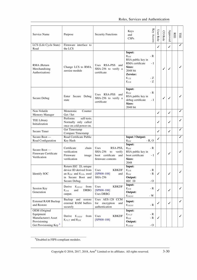
3.2 Services
Table 6 below lists the services offered by CryptoCell-712, along with a concise description ofpurpose, the list of security functions offered or used by the service, a list of keys in use andthe access types for each, the role that can access that service, the Approved or Non-Approvedstatus, whether it’s supported in TEE or REE, and the operator’s access rights to any keys andCSPs involved.
Note that when a service is implemented by both REE and TEE, the same hardware is beingused, with different firmware components passing the arguments and triggering the operations.
Access to keys is denoted with a single letter:
• I — input keys from the user,• O — output keys to the user,• R — read keys from internal storage,• W — write keys to internal storage,• Z — zeroize.
Access type is defined by the perspective of the module or the service. Input and read access alsoincludes any internal usage for the read key.
Copyright © 2016, 2017, 2018, Arm® Limited or its affiliates. All rights reserved. 3-25

Roles, Services and Authentication
Table 6: Services
Service Name Purpose Security FunctionsKeysandCSPs
Key
Access
UserR
ole
CO
Role
Approved
RE
E
TE
E
AES — TEEApproved
EncryptionDecryption
AES-128, 192, 256ECB, CBC, CTR,OFB, CMAC, XTS,CTS (CBC-CS1)
Input:User keys - IKCST - RKDR - RKSESS - RKPLT - R1
3 33
AES — TEENon-Approved modes
EncryptionDecryption
AES-128, 192, 256XCBC-MAC
Input:User keys - IKCST - RKDR - RKSESS - RKPLT - R
33
AES — REEApproved
EncryptionDecryption
AES-128, 192, 256ECB, CBC, CTR,OFB, CMAC, XTS,CTS (CBC-CS1),ESSIV, BitLocker
Input:User keys - IKey slots - R
3 3 3
AES — REENon-Approved modes
Messageauthentication
AES-128, 192, 256modes: XCBC-MAC,GCM, GMAC
Input:User keys - IKey slots - R
3 3
Triple-DESApproved
EncryptionDecryption
Triple-DES ECB, CBCwith three-key bundles(DED and EDE)
Input:User keys - I
3 3 33
Two-Key Triple-DESNon-Approved
EncryptionDecryption
Triple-DES ECB, CBCwith two-key bundles(DED and EDE)
Input:User keys - I
33
DESNon-Approved
EncryptionDecryption
DES ECB, CBCInput:User keys - I
33
SHAApproved
Messageauthentication
SHA-12, SHA-224,SHA-256, SHA-384,SHA-512
3 3 33
MD5Non-Approved
Legacy messageauthentication
MD5 3 33
HMAC Approvedfunctions
Messageauthentication
HMAC SHA-1,SHA-224, SHA-256,SHA-384, SHA-512
Input:User keys - I
3 3 33
HMAC-MD5Non-Approved
Legacy messageauthentication
HMAC-MD5Input:User keys - I
3 33
1KDR is limited by firmware to use in key derivation only. KSESS and KPLT are internally used by the module forencryption/decryption, and the operator is instructed to use those keys only for encryption or decryption, to conformto [SP800-57] Section 5.2 “Key Usage”.
2SHA-1 is not approved for signature generation, Approved for legacy signature verification and other uses.
Copyright © 2016, 2017, 2018, Arm® Limited or its affiliates. All rights reserved. 3-26

Roles, Services and Authentication
Service Name Purpose Security FunctionsKeysandCSPs
Key
Access
UserR
ole
CO
Role
Approved
RE
E
TE
E
NIST SP800-108 KeyDerivation FunctionApproved
KBKDF (Key BasedKey DerivationFunction) [SP800-108]
KDF in Counter Mode.AES-128 or AES-256in CMAC mode
Input:User keys - IKDR - RKPLT - RKOEM - IOutput:User keys - OKSESS - WKPLT - WKOEM - O
3 33
NIST SP800-135 KeyDerivation FunctionsApproved
Key derivation[SP800-135]3.
SHA-1, SHA-224,SHA-256, SHA-384,SHA-512
Input:User keys - IOutput:User keys - O
3 33
KDF1 and KDF2 KeyDerivation FunctionsNon-Approved
Key derivationfunctions KDF1and KDF2[ISO/IEC-18033-2]
SHA-1, SHA-224,SHA-256, SHA-384,SHA-512
Input:User keys - IOutput:User keys - O
33
Endorsement KeyDerivation
Derive theEndorsement KeyECC key-pair
ECC key pairgeneration4
Input:KDR - ROutput:PubKS - OPrivKS - O
3 33
RPMB (ReplayProtected MemoryBlock) Key Derivation
Derive KRPMB fromKDR using KBKDF[SP800-108]
KBKDF
Input:KDR - ROutput:KRPMB - O
3 33
RPMB Page MACGeneration
RPMB Frameauthentication[JESD84]
HMAC SHA-256Input:KRPMB - I
3 33
ECC (Elliptic CurveCryptography) KeyGenerationApproved
ECC key generation[FIPS-186-4]
Curves:P-224, P-256, P-384,P-521, p224k1,p256k1.5
Uses DRBG.
Output:User keys - OSizes:224, 256, 384, 521 bits
3 33
ECC (Elliptic CurveCryptography) KeyGenerationNon-Approvedstrengths
ECC key generation[FIPS-186-4]
Curves:P-192, p160k1, p160r1,p160r2, p192k1, 6
user-defined domains.Uses DRBG.
Output:User keys - OSizes:160, 192 bits
33
ECC Public KeyValidation
Public key validationInput:User keys - I
3 33
3This includes key derivation methods ASN1DER and Concatenation specified in [ANSI-X9.42, 7.7.1]and [ANSI-X9.63, 5.6.3], approved when used as part of a [SP800-56A] agreement scheme
4The private key is derived according to [FIPS-186-4, Section B.4.1], but instead of a random input from a RBG(Random Bit Generator), the procedure uses the result of a [SP800-108] KBKDF applied to the KDR. The resultingkey pair has a different value per module, permanent until zeroization.
5Security strengths for non-NIST-recommended curves: p224k1 — 112 bits, p256k1 — 128 bits.6Security strengths for non-NIST-recommended curves: p160k1, p160r1, p160r2 — 80 bits, p192k1 — 96 bits.
Copyright © 2016, 2017, 2018, Arm® Limited or its affiliates. All rights reserved. 3-27

Roles, Services and Authentication
Service Name Purpose Security FunctionsKeysandCSPs
Key
Access
UserR
ole
CO
Role
Approved
RE
E
TE
E
ECDSA (EllipticCurve DigitalSignature Scheme)Approved
SigningVerification[FIPS-186-4]
SHA functions
Input:User keys - ISizes:224, 256, 384, 521 bits
3 33
ECDSANon-Approvedstrengths
SigningVerification[FIPS-186-4]
SHA functionsNon-approved whenusing non-approvedkey sizes and domains.
Input:User keys - ISizes:160, 192 bits;user-defined domains.
33
EC-DH (Elliptic CurveDiffie Hellman)Approved
Key Agreement[SP800-56A]
EC-DH
Input:User keys - IOutput:User keys - OSizes:224, 256, 384, 521 bits
3 33
EC-DH (Elliptic CurveDiffie Hellman)Non-Approvedstrengths
Key Agreement[SP800-56A]
EC-DH, when usingnon-approved key sizesand domains.
Input:User keys - IOutput:User keys - OSizes:160, 192 bits;user-defined domains.
33
ECIES (Elliptic CurveIntegrated EncryptionScheme)Non-Approved
Key Transport[ISO/IEC-18033-2]
ECIES-KEM[ANSI-X9.63]KDF with SHAfunctionsUses DRBG.
Input:User keys - IOutput:User keys - OSizes:160, 192, 224, 256,384, 521 bits;user-defined domains.
33
RSA Key GenerationApproved
Key pair generation(regular and CRT)[FIPS-186-4]
Uses DRBG
Output:User keys - OSizes:2048, 3072 bit
3 33
RSA Key GenerationNon-Approvedstrengths
Key pair generation(regular and CRT)[FIPS-186-4]
Uses DRBG
Output:User keys - OSizes:1024, 4096 bit
33
RSA Signing andVerificationApproved
PSS signing andverification [FIPS-186-4]
RSASHA-1 (legacyverification only)SHA-224, SHA-256,SHA-384, SHA-512DRBG
Input:User keys - ISizes:2048, 3072;1024 (legacyverification only)
3 33
RSA Signing andVerificationNon-Approved sizes orfunctions
PSS andRSAES-OAEP signingand verification[FIPS-186-4, PKCS1]
RSASHA functionsPKCS1.5 with MD5DRBG
Input:User keys - ISizes:1024, 4096
33
RSA Key WrappingAllowed
RSAES-PKCS1-v1.5and RSAES-OAEPencryption anddecryption [PKCS1]
RSASHA-1, SHA-224,SHA-256, SHA-384,SHA-512DRBG
Input:User keys - ISizes:2048, 3072
33
Copyright © 2016, 2017, 2018, Arm® Limited or its affiliates. All rights reserved. 3-28

Roles, Services and Authentication
Service Name Purpose Security FunctionsKeysandCSPs
Key
Access
UserR
ole
CO
Role
Approved
RE
E
TE
E
RSA Encryption andDecryptionNon-Approved
RSAES-PKCS1-v1.5and RSAES-OAEPencryption anddecryption[FIPS-186-4, PKCS1]with non-approvedsizes
RSASHA-1, SHA-224,SHA-256, SHA-384,SHA-512PKCS1.5 with MD5DRBG
Input:User keys - ISizes:1024, 4096
33
Diffie-Hellman KeyGenerationApproved
Key GenerationDomain ParameterGeneration[SP800-56A]
Uses DRBG
Output:User keys - OSizes:2048 bits
3 33
Diffie-Hellman KeyGenerationNon-Approvedstrengths
Key GenerationDomain ParameterGeneration[SP800-56A]
Uses DRBG
Output:User keys - OSizes:1024 bits
33
Diffie-Hellman Keyand DomainVerificationApproved
Key VerificationDomain ParameterVerification[SP800-56A]
Input:User keys - I
3 33
Diffie-Hellman KeyExchangeApproved
Key Agreement[SP800-56A]
SHA functions
Input:User keys - IOutput:User keys - OSizes:2048
3 33
Diffie-Hellman KeyExchangeNon-Approvedstrengths
Key Agreement[SP800-56A]
SHA functions
Input:User keys - IOutput:User keys - OSizes:1024
33
DRBG (DeterministicRandom Bit Generator)Instantiation
DRBG ContextInstantiation
Creates a DRBGcontext structure, usingTRNG internally forseeding.
Output:DRBG context(V, Key) - O
3 33
DRBG ReseedingDRBG Reseeding withoptional AdditionalInput [SP800-90A]
Input / Output:DRBG context(V, Key) - I, O
3 33
DRBG Generation
Generate RandomVectorGenerate RandomVector in Range[SP800-90A]
CTR-DRBG(AES-256 in CTRmode)
Input / Output:DRBG context(V, Key) - I, O
3 33
DRBG TestingEnable KAT modeDisable KAT mode
Auxiliary functionsused to perform a KAT(Known Answer Test)7
3 33
Set Key SlotSet key from TEE tobe used in REE AESalgorithms
Input:User keys - IOutput:Key slots - W
3 33
7The operator is instructed not to call those functions at run time, they are intended for power-on testing only.
Copyright © 2016, 2017, 2018, Arm® Limited or its affiliates. All rights reserved. 3-29
Roles, Services and Authentication
Service Name Purpose Security FunctionsKeysandCSPs
Key
Access
UserR
ole
CO
Role
Approved
RE
E
TE
E
LCS (Life Cycle State)Read
Firmware interface tothe LCS
3 33
RMA (ReturnMerchandisingAuthorization)
Change LCS to RMA,zeroize module
Uses RSA-PSS andSHA-256 to verify acertificate
Input:HBK - RRSA public key inRMA certificate - ISizes:2048 bitZeroize:KCE - ZKDR - Z
3 33
Secure DebugEnter Secure Debugstate
Uses RSA-PSS andSHA-256 to verify acertificate
Input:HBK - RRSA public key indebug certificate - ISizes:2048 bit
3 33
Non-VolatileMemory Manager
Monotonic CounterGet / Set
3 33
TEE LibraryInitialization
Performs self-tests.Normally only calledonce on cold power-on.
3 33
Secure TimerGet TimestampCompare Timestamp
3 33
Secure Boot —Read Configuration
Read Certificate PublicKey Hash
Input / Output:HBK - R, O
33
Secure Boot —Firmware CertificateVerification
Certificate chainverificationFirmware imageverification
Uses RSA-PSS,SHA-256 to verifyboot certificate andfirmware contents
Input:HBK - RRSA public key inboot certificate - ISizes:2048
3 33
Identify SOC
Return SOC ID, uniquedevice ID derived froman HBK and KDR, usedin Secure Boot andSecure Debug.
Uses KBKDF[SP800-108] andSHA-256
Input:KDR - RHBK - ROutput:SOC ID - O
3 33
Session KeyGeneration
Derive KSESS fromKDR and DRBGoutput.
Uses KBKDF[SP800-108]Uses DRBG
Input:KDR - ROutput:KSESS - W
3 33
External RAM Backupand Restore
Backup and restoreexternal RAM bufferssecurely
Uses AES-128 CCMfor encryption andauthentication
Input:KSESS - R
3 33
OEM (OriginalEquipmentManufacturer) AssetProvisioningGet Provisioning Key 8
Derive KOEM fromKPLT and HBK
Uses KBKDF[SP800-108]
Input:KPLT - RHBK - ROutput:KOEM - O
33
8Disabled in FIPS-compliant modules.
Copyright © 2016, 2017, 2018, Arm® Limited or its affiliates. All rights reserved. 3-30
Roles, Services and Authentication
Service Name Purpose Security FunctionsKeysandCSPs
Key
Access
UserR
ole
CO
Role
Approved
RE
E
TE
E
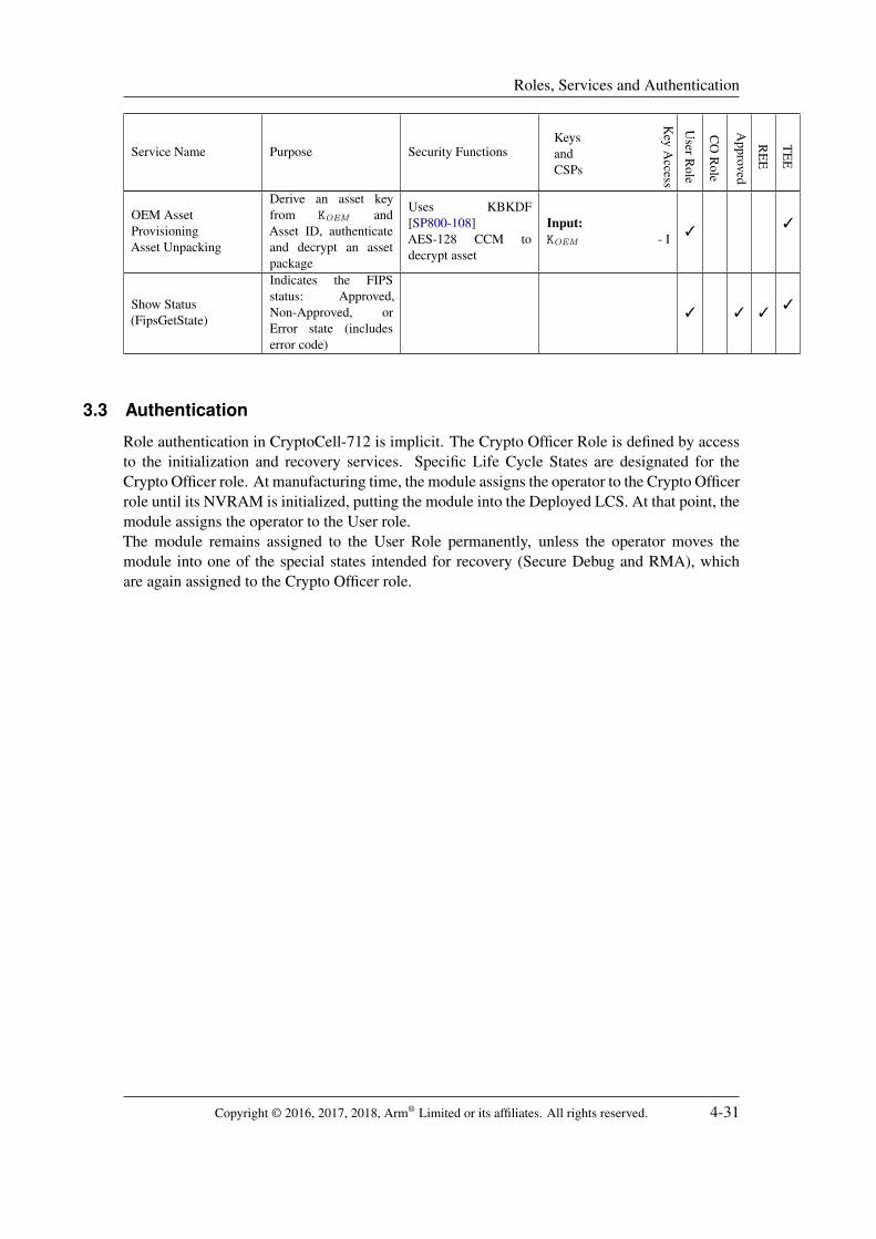
OEM AssetProvisioningAsset Unpacking
Derive an asset keyfrom KOEM andAsset ID, authenticateand decrypt an assetpackage
Uses KBKDF[SP800-108]AES-128 CCM todecrypt asset
Input:KOEM - I
33
Show Status(FipsGetState)
Indicates the FIPSstatus: Approved,Non-Approved, orError state (includeserror code)
3 3 33
3.3 Authentication
Role authentication in CryptoCell-712 is implicit. The Crypto Officer Role is defined by accessto the initialization and recovery services. Specific Life Cycle States are designated for theCrypto Officer role. At manufacturing time, the module assigns the operator to the Crypto Officerrole until its NVRAM is initialized, putting the module into the Deployed LCS. At that point, themodule assigns the operator to the User role.The module remains assigned to the User Role permanently, unless the operator moves themodule into one of the special states intended for recovery (Secure Debug and RMA), whichare again assigned to the Crypto Officer role.
Copyright © 2016, 2017, 2018, Arm® Limited or its affiliates. All rights reserved. 4-31

Finite State Model
4 Finite State Model
CryptoCell-712 life cycle and operational states follow a FSM (Finite State Model), fullydescribed in the separate FSM document. The module LCS (Life Cycle State) is tied to userroles and affect the module functionality, a summary is given below.
4.1 Deployed states
Power OffThe module do not receive power and it is completely off. No functionality available untilpower-on.
Cold Power-onFollowing cold power-on, the module’s Non-Volatile Memory Manager (Section 1.4.1.2.2)determines the LCS from a dedicated OTP field, and goes to Deployed, or one of theManufacturing and recovery states below. If the OTP indicates Deployed but the moduleNVRAM contains a valid debug certificate in a designated area, the module enters SecureDebug.
DeployedA module in the field normally starts in the Deployed LCS. The module initializes andgoes to the Self-Test state. Module services can be invoked to enter RMA or SecureDebug states, but this will only take effect on the next cold power-on.
Self-TestPerforms FIPS power-on tests. If those fail, goes to the Error state. Otherwise, goes toeither Approved or Non-Approved state according to input from the Host platform.
ErrorThe FIPS error state is entered from the Self-Test state or Approved Mode, if a power-onor conditional test fails. All data output is blocked. On power-on reset, the module returnsto Deployed state.
Approved ModeFIPS-Approved mode of operation. FIPS-approved functions are available for use. Themodule may enter Error state if a conditional test fails. On power-on reset the modulereturns to Deployed state.
Non-Approved ModeNon-FIPS-approved mode of operation. All functions are available for use. On power-onreset the module returns to Deployed state.
Secure DebugThis state is non-terminal and non-permanent, and is not recorded in the OTP. It isassociated with the Crypto Officer. The device will enter this state on cold power-on ifa valid certificate is present in a dedicated location in NVRAM. On power-on reset themodule returns to Deployed state, if the certificate is removed. See Section 1.4.1.4.7 fordetails.
4.2 Manufacturing and recovery states
Chip ManufacturingThe initial LCS. At manufacturing, the ICV (Independent Chip Vendor) uses the CMPU(Chip Manufacturing Production Utility) provided by Arm® to securely initialize theKDR. On completion, the module transitions to Device Manufacturing on the next cold
Copyright © 2016, 2017, 2018, Arm® Limited or its affiliates. All rights reserved. 4-32

Finite State Model
power-on.Device Manufacturing
The OEM initializes all remaining security assets in module NVRAM. On completion, themodule transitions to Deployed on the next cold power-on. The manufacturer may insteadput the module into the Security Disabled state.
Security DisabledThe manufacturer may opt to block the security functionality of some modules. This stateis terminal (the module will return to it on each cold power-on). Secure Boot and allcryptography functions are disabled in this state.
RMAThe RMA (Return Merchandising Authorization) state is for devices that return to themanufacturer for failure analysis. This state is entered by placing a manufacturer certificatein NVRAM, and then using the RMA service and a cold power-on. Modules in theRMA state zeroize and block access to platform keys (see Section 7.2.1), but retain fullcryptographic functionality9. This state is terminal (the module will return to it on eachcold power-on).
9Modules with encrypted firmware will halt with error during boot, since the firmware encryption key is zeroized.
Copyright © 2016, 2017, 2018, Arm® Limited or its affiliates. All rights reserved. 5-33

Physical Security
5 Physical Security
CryptoCell-712 is a sub-chip module provided as set of RTL and firmware sources. The moduleshall be synthesized in a single host chip with standard passivation and a production gradeenclosure that prevents access to the interior of the module and conforms to level 1 requirementsfor physical security.
Copyright © 2016, 2017, 2018, Arm® Limited or its affiliates. All rights reserved. 6-34

Operational Environment
6 Operational Environment
The module’s operational environment is non-modifiable. The module does not containa mechanism to update its firmware. In addition, the module uses integrity techniques(Section 9.1.2) to enforce the non-modification of its firmware.The operational environment for CryptoCell-712, as implemented for this validation, is the LinuxOS kernel version 3.18.The module’s TEE firmware is a static library providing cryptographic services for the OSthrough API function calls. The TEE firmware’s interface to the hardware is direct, doneusing memory and register operations and interrupts; the module does not use OS services toaccess its hardware, and therefore has no functional dependency on the OS. Any variation in OSmechanisms, such as memory allocators and synchronization primitives, is accounted for by thePAL (Platform Adaptation Layer) (Section 1.4.1.4.8).
Copyright © 2016, 2017, 2018, Arm® Limited or its affiliates. All rights reserved. 7-35

Cryptographic Key Management
7 Cryptographic Key Management
CryptoCell-712 works with three types of keys: user keys, platform keys, and key slots(Section 1.4.1.1.2). Table 7 summarizes the keys defined in the module.
Table 7: Module keys and CSPs
Key Full name Purpose Length Storage Entry and Derivation
User keys N/AUsed with cryptographicservices Various10 User RAM
Plaintext
Input by user or generated bythe module’s cryptographicservices
Key slots N/ASet in TEE for use by REEAES algorithms
128, 192, 256,2∗128, 2∗256bit
HW registersPlaintext
Set by TEE
KDR Device Root KeyDerivation of device-specifickeys
256 bitOTP, HWregisterPlaintext
Generated by DRBG duringmanufacturing, with seedfrom TRNG
KRTLProvisioningMaster Key
Derivation of KPLT 128 bitOTPPlaintext
Written in OTP duringmanufacturing
KPLT Platform KeyEither decryption of KCST orderivation of KOEM
11 128 bitHW registerPlaintext
Derived using KBKDF fromKRTL and HBK .
EKCSTEncryptedCustomer Key
Stores KCST encrypted withKPLT
128 bitOTPEncrypted
Written by OEM duringmanufacturing
KCST Customer KeyUsed as a key for customerassets
128 bitHW registerPlaintext
Decrypted on boot withAES-128 ECB from EKCST
with KPLT as key
KOEM
OEMProvisioningKey
OEM asset decryptionand verification.Non-FIPS-compliantmodules only.
128 bitHost SRAMPlaintext
Derived using KBKDF fromKPLT and HBK
PubKBK0
PubKBK1
Boot key 0Boot key 1
Certificate verification forSecure Boot, Secure Debugand RMA
1∗2048 bit or2∗2048 bit
NVRAM(Flash)Plaintext
One or two boot keys,written by OEM duringmanufacturing
HBKHash of BootKey
Boot key integrity protection(SHA-256 hash of one of theboot keys)12
1∗256 bit or2∗128 bit
OTPPlaintext
Written by OEM duringmanufacturing
KCEFirmware CodeEncryption key
Optional: firmware imagedecryption as part of SecureBoot
128 bitOTP andSRAMPlaintext
Written by OEM duringmanufacturing
KSESS Session keyUsed in the RAM Backupservice
128 bitHW registerPlaintext
Derived using KBKDF fromKDR and a 96-bit randomvalue
PubKSPrivKS
Endorsement keypair
ECDSA signing of devicemessages
256 bitHost SRAMPlaintext
Derived according to[FIPS-186-4, B.4.1] 13
KRPMBRPMB sharedkey
Computing HMACs forRPMB data frames
256 bitHost SRAMPlaintext
Derived from KDR usingKBKDF
10See Table 8 for key lengths used.11To comply with [SP800-57, 5.2], KCST must be limited to one usage type. FIPS-compliant modules only use
KPLT to decrypt KCST . Non-compliant modules derive KOEM and offer the OEM Asset Provisioning service instead.The configuration is set in permanent NVRAM per module.
12HBK may instead hold two SHA-256 hashes truncated to 128 bits, to verify both PubKBK0 and PubKBK1 .Otherwise only one boot key can be used. The use of SHA-256 hashes truncated to 128 bits is approved accordingto [SP800-107, 5.1]
13Instead of a random input from a RBG, the procedure uses the result of KBKDF applied to the KDR. The resultingkey pair value is fixed per module.
Copyright © 2016, 2017, 2018, Arm® Limited or its affiliates. All rights reserved. 7-36

Cryptographic Key Management
7.1 User Keys
User keys are created and owned by the module’s user — application firmware running on theHost CPU in the TEE and REE. From the module’s perspective, user keys are transient, andthe module never stores them in non-volatile memory. The module may copy user keys into itsinternal RAM and cryptographic engine registers, and will clear them on completion of everyoperation and on zeroization.
Table 8: User key sizesAlgorithm Key sizesAES 128, 192, 256 bitsDES 64 bitsTriple-DES 128, 192 bitsHMAC up to 226 bytesKBKDF up to 4080 bytesSP800-135 up to 2048 bytesKDF1, KDF2 up to 2048 bytesECC 160, 192, 224, 256, 384, 521 bitsRSA 1024, 2048, 3072, 4096 bitsDiffie-Hellman 1024, 2048 bits
7.2 Platform Keys
Platform keys are named keys with a specific purpose. Several platform keys are stored in themodule’s OTP. Those keys are used to derive additional platform keys during the boot sequence,or on demand. Most platform keys are stored in dedicated HW registers and are limited by thehardware to specific uses, but some of the derived keys are output to the user.The following keys are not FIPS-compliant, and are disabled by configuration in modules passingFIPS certification:
• The provisioning key KOEM is derived and output to the user before the module completesself-tests, and therefore FIPS-certified modules are configured to disable KOEM and use thealternative provisioning key KCST instead.
7.2.1 Blocking access to Platform Keys
The module blocks access to platform keys in the RMA and Secure Debug states, to preventCrypto Officer access to plaintext platform keys. In the RMA state, root keys are permanentlyzeroized. In the Secure Debug state, the registers for root keys are either masked with temporaryvalues or cleared to zero, but the OTP value remains, so this does not constitute FIPS 140-2zeroization. Other keys derived from root keys are also affected. The exact effects are detailedin Table 9.Key slots (Section 1.4.1.1.2) are also masked. User keys are cleared by the power-on reset onentry to those modes.In effect, all platform keys are made inaccessible, and so is any content encrypted with themprior to zeroization. Two OTP keys, KDR and KCE , are erased upon entry to RMA. EKCST isstored in ciphertext and cannot be decrypted following zeroization.
Copyright © 2016, 2017, 2018, Arm® Limited or its affiliates. All rights reserved. 7-37

Cryptographic Key Management
Table 9: Blocking access to platform keys
Key Secure Debug RMAKDR Masked Erased in OTPKCE No effect Erased in OTPKRTL Masked Erased in OTPKPLT Cleared ClearedEKCST No effect No effectKCST Cleared ClearedKOEM Cleared ClearedKSESS Alternative value Alternative valueKRPMB Alternative value Alternative valuePubKS , PrivKS Alternative value Alternative value
7.3 Key generation
CryptoCell-712 uses a DRBG compliant with [SP800-90A], seeded with at least 384 bits ofentropy from a TRNG. See Sections 1.4.1.2.4, 1.4.1.4.5 for details on the TRNG and DRBGimplementations.Asymmetric key generation services offered by the module are defined by the [FIPS-186-4]standard, use the DRBG service for random inputs, and are detailed in Section 3.2. No dedicatedservice is offered for symmetric key generation; the operator is instructed to directly use theoutput of the DRBG service.Internally, the module uses the DRBG to generate the session key KSESS (Table 7) and to providerandom inputs to cryptographic services that use randomness (RSA and ECIES).For initializing the Device Root Key KDR during the manufacturing process, Arm® offers itspartners a CMPU which executes on the module during manufacturing. The CMPU performsFIPS self-tests before using the module’s TRNG to seed the DRBG and generate the KDR
internally. Alternatively, an OEM may generate the KDR externally and burn it into the module’sOTP.
7.4 Key establishment
Key establishment and key derivation services offered by the module are detailed inSection 3.2. The module offers key establishment services based on the approved Elliptic CurveDiffie-Hellman and Finite Field Diffie-Hellman algorithms [SP800-56A], and the non-approvedECIES (Elliptic Curve Integrated Encryption Scheme) [IEEE1363]. The module does not offerkey establishment services based on the RSA algorithm.The module offers approved key derivation services using Key Derivation Functions as definedin [SP800-108, SP800-135]: KBKDF, CVL ANS X9.63-2001, and ASN1DER.In addition, Non-Approved key derivation services are available for use in Non-Approved Mode:the KDF1 and KDF2 functions as defined in [ISO/IEC-18033-2].For internal key establishment, the module’s Approved services follow the guidelinesof [SP800-57] with regards to required key strengths. All internal key derivations are performedwith approved algorithms, and the derived keys are of strength less or equal than the source key,ensuring that the derived keys have full cryptographic strength, for all Approved key sizes.When using the module’s DRBG for key generation, a 256-bit key size and state are used,
Copyright © 2016, 2017, 2018, Arm® Limited or its affiliates. All rights reserved. 7-38

Cryptographic Key Management
resulting in a security strength of up to 256 bits.
7.5 Key entry and output
The module supports electronic key entry methods only. The module does not support manualkey import or export methods. User keys are input and output electronically, in plaintext, asparameters to the module’s firmware APIs. Platform keys are only input into the module duringmanufacturing.The module does not receive seeds and seed keys from the outside. The DRBG is only seededand re-seeded from the TRNG.
7.6 Key storage
User keys within the module are stored only temporarily and in plaintext form.Key slots are stored in dedicated hardware registers, in plaintext.Several platform keys are persistently stored either in OTP or RTL; platform keys may be keptin HW registers or SRAM at runtime. For a list of platform keys and their storage locations, seeTable 7. All Platform keys are stored in plaintext, with the exception of EKCST , the encryptedversion of KCST .
7.7 Key zeroization
The user can zeroize User Keys in the module at any time by putting the module through apower-on reset or a warm reset. The module explicitly erases the portions of SRAM which mayhold keys, CSPs and intermediate values. The PKA SRAM and the work buffer described inSection 7.1 are cleared on every cryptographic operation, and following power-on reset.The user can zeroize keys in Key Slots (Section 1.4.1.1.2) at any time by calling the TEE serviceto set the key slots to zero. Key slots are cleared on cold power-on but survive a warm reset.For platform keys, the entry to RMA mode is used as the zeroization technique. The procedureto zeroize the module through RMA is as follows:
1. The operator places a valid Secure Debug certificate (Section 1.4.1.4.7) with an RMA flag inthe designated area of NVRAM.
2. The operator puts the module through a power-on reset. During boot, the certificate is verifiedand the RMA state becomes available.
3. The operator invokes the RMA service to enter the RMA state.4. The operator puts the module through a power-on reset again.5. The operator can use the LCS Read service to verify that the device has indeed entered RMA
mode.
Following the second power-on reset, platform keys are erased or made unavailable as describedin Section 7.2.1.
Copyright © 2016, 2017, 2018, Arm® Limited or its affiliates. All rights reserved. 8-39

Electromagnetic Interference / Compatibility (EMI/EMC)
8 Electromagnetic Interference / Compatibility (EMI/EMC)
The module meets the applicable FCC EMI/EMC requirements for FIPS 140-2 level 1.
Copyright © 2016, 2017, 2018, Arm® Limited or its affiliates. All rights reserved. 9-40
Self Tests
9 Self Tests
According to FIPS 140-2 requirements, CryptoCell-712 performs a number of self-tests onpower-up and conditionally on selected events.
9.1 Power-up tests
The following tests are performed on module initialization, before the operator can request anyof the module’s cryptographic services. The tests are performed automatically, without needingany action from an operator. A platform-global variable is used to synchronize the state ofthe power-on self-tests between the TEE and the REE, preventing data output before self-testscomplete.A failure of any of these tests will cause the module to enter the Error state, which is indicatedby the status output. On success, the module will enter the Approved or Non-Approved state asrequested by the Host, and will change its status output accordingly.The module’s TEE Library Initialization performs power-up tests, but is normally only calledonce on cold power-on. The operator can initiate a power-on reset to have the module performthe tests.
9.1.1 Cryptography test
The module performs KAT (Known Answer Test) on power-up with the cryptographic algorithmsas listed below. All tests perform a comparison versus a stored reference value, unless explicitlynoted for pairwise tests.
9.1.1.1 Tests repeated in both TEE and REEThe following tests are performed twice, once in the TEE and once in the REE. The module doesnot perform comparison tests between the different implementations.
• AES encryption and decryption operations, in ECB, CBC, OFB, CTR and CTS (CBC-CS1)modes, using 128, 192, and 256-bit key sizes.
• XTS-AES encryption and decryption operations, using 256 bit key size.• AES MAC generation in CCM mode, using 128, 192, and 256-bit key sizes.• Triple-DES encryption and decryption operations, ECB and CBC modes, with 3-key bundles.• Hash generation for SHS with SHA-1, SHA-256, and SHA-512.• HMAC generation for HMAC SHA-256.
9.1.1.2 Tests in REEThe following tests are performed in the REE only:
• AES authentication in GCM and GMAC mode, using 128, 192, and 256-bit key sizes.
9.1.1.3 Tests in the TEEThe following tests are performed in the TEE only.
• AES MAC generation with CBC-MAC using 128-bit and 256-bit keys.• XTS-AES encryption and decryption operations, using 512 bit key size.• Triple-DES encryption and decryption operations, ECB and CBC modes, with 2-key bundles.• DRBG Instantiate, Reseed with Additional Input, and random vector generation.
Copyright © 2016, 2017, 2018, Arm® Limited or its affiliates. All rights reserved. 9-41

Self Tests
• RSA encryption and decryption with 2048-bit modulus, using PKCS#1v2.1 OAEP scheme.• RSA signature generation and verification with 2048-bit modulus, using PKCS#1v2.1 PSS
scheme. The PSS scheme has its random input disabled for this test.• ECDSA signature generation and verification using the P-256 curve, with the SHA-256
message digest.• KAS DH — Primitive “‘z”’ operation (as part of a NIST SP800-56A key agreement), with
prime size of 2048 bits.• KAS EC-DH — Primitive “‘z”’ operation (as part of a NIST SP800-56A key agreement
protocol), using the P256 curve.
Note: the boot-time Firmware Certificate Verification service has its own implementation of theRSA-PSS scheme. This is used in module’s boot process to verify the firmware image integrity,and constitutes a KAT (Known Answer Test) of the algorithm.
9.1.2 Firmware integrity test
The module performs firmware integrity tests as part of the boot sequence.The TEE Boot ROM integrity is checked using the SHA-256 function, computed over the entiretyof the ROM and compared with a value stored in the firmware image.The TEE and REE firmware integrity is checked as part of Secure Boot (Section 1.4.1.4.6), usingthe Verify Boot Image service (RSA-2048 PSS with SHA-256).
9.2 Conditional tests
Upon RSA and ECC key generation, a conditional test is run. Since the key’s intended use (forencryption and decryption, or for signature creation and verification) is unknown at the timeof generation, each algorithm is tested for pairwise consistency with one usage: RSA is testedwith an encryption and decryption operation, and ECC is tested with a signature generation andverification operation.The CRNGT (Continuous Random Number Generator Test) is implemented in the module’stwo approved random number generators — the TRNG and the DRBG. In both, each block ofoutput generated is compared for equality with the previous block (exempting the very first blockgenerated). The TRNG uses a block size of 16 bits. The DRBG uses a block size of 128 bits.A failure of either CRNGT (Continuous Random Number Generator Test) will put the entiremodule into the Error State.
Copyright © 2016, 2017, 2018, Arm® Limited or its affiliates. All rights reserved. 10-42

Design Assurance
10 Design Assurance
10.1 Guidance
10.1.1 Operator guidance
• The operator is instructed not to use functions and key sizes marked as Non-Approved in FIPSmode.
• The operator is instructed to follow the additional caveats on approved functions(Section 1.3.1).
• When using the module’s services for key derivation and key establishment, the operator isinstructed to follow NIST guidelines on the relative strengths of source key and derived key,or the asymmetric key used to establish a shared symmetric key.
• When receiving another party’s public key in the Diffie-Hellman and Elliptic-CurveDiffie-Hellman protocols, the operator is instructed to invoke the Domain ParameterVerification service is order to fulfill the requirements of [SP800-56A] section 5.6.2.
10.2 Proprietary documentation
The following proprietary documents are available to Arm® partners for this product:
• Arm® TrustZone® CryptoCell-712 Configuration and Integration Manual• Arm® TrustZone® CryptoCell-712 Technical Reference Manual• Arm® TrustZone® CryptoCell-712 Software Integration Manual• Arm® TrustZone® CryptoCell-712 Software Developers Manual• Arm® TrustZone® CryptoCell-712 TRNG Characterization Application Note
Copyright © 2016, 2017, 2018, Arm® Limited or its affiliates. All rights reserved. 11-43
Mitigation of Other Attacks
11 Mitigation of Other Attacks
The cryptographic module is not designed to mitigate specific attacks.
Copyright © 2016, 2017, 2018, Arm® Limited or its affiliates. All rights reserved. 11-44

Glossary
Glossary
AIB Intel Asynchronous Interface Bus SpecificationAPB AMBA Peripheral BusAXI Advanced eXtensible InterfaceCMPU Chip Manufacturing Production UtilityCRNGT Continuous Random Number Generator TestCRYS Cryptographic Software LibraryCSP Critical Security ParameterDCU Debug Control UnitDH Diffie-HellmanDMA Direct Memory AccessDRBG Deterministic Random Bit GeneratorDRM Digital Rights ManagementEC-DH Elliptic Curve Diffie HellmanECC Elliptic Curve CryptographyECDSA Elliptic Curve Digital Signature SchemeECIES Elliptic Curve Integrated Encryption SchemeFFC Finite Field CryptographyFPGA Field Programmable Gate ArrayFSM Finite State ModelHAL Host Adaptation LayerHW HardwareICV Independent Chip VendorIP Intellectual PropertyISV Independent Software VendorIV Initialization VectorKAS Key Agreement SchemeKAT Known Answer TestKBKDF Key Based Key Derivation FunctionLCS Life Cycle StateMAC Message Authentication CodeNVRAM Non Volatile Random Access MemoryOEM Original Equipment ManufacturerOS Operating SystemOTP One-Time Programmable memoryPAL Platform Adaptation LayerPKA Public Key AcceleratorRAM Random Access MemoryRBG Random Bit GeneratorREE Rich Execution EnvironmentRMA Return Merchandising AuthorizationRNG Random Number GeneratorROM Read-Only MemoryRPMB Replay Protected Memory BlockRTL Register Transfer LanguageSOC System on ChipSRAM Static Random Access MemoryTEE Trusted Execution EnvironmentTRNG True Random Number Generator
Copyright © 2016, 2017, 2018, Arm® Limited or its affiliates. All rights reserved. 45

References
References[AMBA] ARM. AMBA specifications. http://www.arm.com/products/system-ip/amba-specifications.
php.
[ANSI-X9.42] ANSI. ANSI X9.42:2003 agreement of symmetric keys using discrete logarithm cryptography. http://webstore.ansi.org/RecordDetail.aspx?sku=ANSI+X9.42-2003+(R2013), 2003.
[ANSI-X9.63] ANSI. ANSI X9.63 public key cryptography for the financial services industry: Key agreement andkey transport using elliptic curve cryptography. http://webstore.ansi.org/RecordDetail.aspx?
sku=X9.63-2011, 2011.
[FIPS-180-4] FIPS. FIPS PUB 180-4: Secure hash standard (SHS). http://nvlpubs.nist.gov/nistpubs/
FIPS/NIST.FIPS.180-4.pdf, 2015.
[FIPS-186-4] NIST. FIPS PUB 186-4 - digital signature standard (DSS). http://nvlpubs.nist.gov/nistpubs/FIPS/NIST.FIPS.186-4.pdf, 2013.
[FIPS-197] NIST. FIPS 197 - Advanced Encryption Standard (AES). http://csrc.nist.gov/publications/
fips/fips197/fips-197.pdf, Nov 2001.
[FIPS-198-1] FIPS. FIPS PUB 198-1: The keyed-hash message authentication code (HMAC). http://csrc.nist.gov/publications/fips/fips198-1/FIPS-198-1_final.pdf, 2008.
[FIPS-46-3] FIPS. FIPS PUB 46-3 : Data encryption standard (DES). http://csrc.nist.gov/publications/fips/fips46-3/fips46-3.pdf, 1999.
[IEEE1363] IEEE. IEEE 1363-2000: Standard specifications for public key cryptography. http://grouper.ieee.org/groups/1363/P1363/index.html, 2000.
[ISO/IEC-18033-2] ISO/IEC. ISO/IEC 18033-2. http://www.iso.org/iso/iso_catalogue/catalogue_tc/
catalogue_detail.htm?csnumber=37971, 2006.
[ISO/IEC-9797-1:2011] ISO/IEC. ISO/IEC 9797-1:2011 - information technology – security techniques – messageauthentication codes (MACs) – part 1: Mechanisms using a block cipher. http://www.iso.org/iso/
iso_catalogue/catalogue_tc/catalogue_detail.htm?csnumber=50375, 2011.
[JEDEC] JEDEC. JEDEC standard, universal flash storage host controller interface (ufshci), version 2.1. http:
//www.jedec.org/standards-documents/results/jesd223c, Mar 2016.
[JESD84] JEDEC. JEDEC standard, embedded multimedia card (eMMC), electrical standard - version 5.0. http:
//www.jedec.org/sites/default/files/docs/JESD84-B50.pdf, 2014.
[PKCS1] RSA Laboratories. PKCS#1 RSA cryptography standard. http://www.emc.com/emc-plus/rsa-labs/standards-initiatives/pkcs-rsa-cryptography-standard.htm, 2012.
[RFC1321] Ronald Rivest. The MD5 message-digest algorithm. https://www.ietf.org/rfc/rfc1321.txt,1992.
[RFC2104] Hugo Krawczyk, Mihir Bellare, and Ran Canetti. RFC 2104: HMAC: Keyed-hashing for messageauthentication. https://www.ietf.org/rfc/rfc2104.txt, 1997.
[RFC3566] Sheila Frankel and Howard Herbert. RFC 3566-the AES-XCBC-MAC-96 algorithm and its use withIPsec. https://www.ietf.org/rfc/rfc3566.txt, 2003.
[SP800-107] Quynh Dang. NIST special publication 800-107 revision 1: Recommendation for applications usingapproved hash algorithms. http://csrc.nist.gov/publications/nistpubs/800-107-rev1/
sp800-107-rev1.pdf, 2012.
[SP800-108] Lily Chen. NIST special publication 800-108: Recommendation for key derivation usingpseudorandom functions. http://csrc.nist.gov/publications/nistpubs/800-108/sp800-108.
pdf, 2009.
[SP800-133] NIST. SP 800-133: Recommendation for cryptographic key generation. http://nvlpubs.nist.
gov/nistpubs/SpecialPublications/NIST.SP.800-133.pdf, 2012.
[SP800-135] Quynh Dang. NIST special publication 800-135 revision 1: Recommendation for existingapplication-specific key derivation functions. http://nvlpubs.nist.gov/nistpubs/Legacy/SP/
nistspecialpublication800-135r1.pdf, 2011.
[SP800-38A] Morris Dworkin. NIST special publication 800-38A - recommendation for block cipher modes ofoperation. http://csrc.nist.gov/publications/nistpubs/800-38a/sp800-38a.pdf, 2001.
Copyright © 2016, 2017, 2018, Arm® Limited or its affiliates. All rights reserved. 46

References
[SP800-38Aadd] Morris Dworkin. Addendum to NIST special publication 800-38a: Recommendation for blockcipher modes of operation: Three variants of ciphertext stealing for CBC mode. http://csrc.nist.
gov/publications/nistpubs/800-38a/addendum-to-nist_sp800-38A.pdf, 2010.
[SP800-38B] Morris Dworkin. NIST special publication 800-38b: Recommendation for block cipher modes ofoperation: The CMAC mode for authentication. http://csrc.nist.gov/publications/nistpubs/
800-38B/SP_800-38B.pdf, 2005.
[SP800-38C] Morris Dworkin. NIST special publication 800-38c: Recommendation for block cipher modesof operation: The CCM mode for authentication and confidentiality. http://csrc.nist.gov/
publications/nistpubs/800-38C/SP800-38C_updated-July20_2007.pdf, 2004.
[SP800-38D] Morris Dworkin. NIST special publication 800-38d: Recommendation for block cipher modesof operation: Galois/counter mode (GCM) and GMAC. http://csrc.nist.gov/publications/
nistpubs/800-38D/SP-800-38D.pdf, 2007.
[SP800-38E] Morris Dworkin. NIST special publication 800-38e: Recommendation for block cipher modesof operation: The XTS-AES mode for confidentiality on storage devices. http://csrc.nist.gov/
publications/nistpubs/800-38E/nist-sp-800-38E.pdf, 2010.
[SP800-56A] Elaine Barker, Lily Chen, Allen Roginsky, and Miles Smid. NIST special publication 800-56a revision2: Recommendation for pair-wise key establishment schemes using discrete logarithm cryptography. http://nvlpubs.nist.gov/nistpubs/SpecialPublications/NIST.SP.800-56Ar2.pdf, 2013.
[SP800-57] Elaine Barker, William Barker, William Burr, William Polk, and Miles Smid. NIST special publication800-57: Recommendation for key management - part 1: General (revision 3). http://csrc.nist.gov/publications/nistpubs/800-57/sp800-57_part1_rev3_general.pdf, 2012.
[SP800-67] William C. Barker and Elaine Barker. NIST special publication 800-67: Recommendation for the tripledata encryption algorithm (TDEA) block cipher. http://csrc.nist.gov/publications/nistpubs/800-67-Rev1/SP-800-67-Rev1.pdf, 2012.
[SP800-90A] NIST. NIST special publication 800-90 A: Recommendation for random number generation usingdeterministic random bit generators. http://dx.doi.org/10.6028/NIST.SP.800-90Ar1, 2015.
Copyright © 2016, 2017, 2018, Arm® Limited or its affiliates. All rights reserved. 47