arm processor programming• protocols : 2 uart, 2 i2c, spi, ssp, usb 2.0 -• power saving modes :...
TRANSCRIPT

ARM Processor – Programming Lecture on ARM7 – LPC2148 - Interfacing programs in C
By
Harish V. Mekali

• ARM7TDMI processor
• 40KB on RAM And 512KB Flash memory
• Up to 45 GPIO pins from two ports => P0[0:25] + P0[28:31] + P1[16:31]
• Operating voltage : 3.3v
• Crystal frequency : upto 60MHz
• 14 analog inputs – with two 10 bit ADCs
• 1 ten bit DAC
• 2 timers / counters
• 6 PWM
• RTC and watchdog timers
• 9 level / edge sensitive external interrupt pins
• Protocols : 2 UART, 2 I2C, SPI, SSP, USB 2.0
• Power saving modes : Ideal and Power down
Features of LPC2148 – LQFP64
Applications : - Point of Sale - Ticketing machine - Access control - Industry control - Medical instruments - Communication gateway / router - Mobile phones / tablets - Automobile applications - General purpose applications


LPC2148 pin mapping on ALS board

GPIO – General Purpose Input Output
LED
Buzzer
Rely with DC motor
Switch


Each port is associated with 4 register 1. Pin function selection as every pin in the controller is multiplexed
– PINSEL register => PINSEL0 for P0[0:15]
PINSEL1 for P0[16:31]
PINSEL2 for P1[16:31]
i.e., for each pin in port, two PINSEL bits are dedicated as there can be 4 functions of each pin
2. Pin direction selection ( Input or Output )
– IODIR register => IO0DIR for PO & IO1DIR for P1
3. Pin value selection (Low or High)
– SET register (High value) => IO0SET for P0 & IO1SET for P1
– Clear register (Low value) => IO0CLR for P0 & IO1CLR for P1
Ex : IO0DIR = 0x00000080; // Pin PORT0.7 configured as output IO0SET = 0x00000080; //Pin PORT0.7 goes HIGH IO0CLR = 0x00000080; //Pin PORT0.7 goes LOW
GPIO(General Purpose Input Output) Pins

#include <LPC21XX.h> unsigned int delay; int main () { PINSEL0 = 0x00000000 ; // Configure P0.0 to P0.15 as GPIO PINSEL1 = 0x00000000 ; // Configure P0.16 to P0.31 as GPIO IO0DIR = 0x00010000 ; // Configure P0.16 as Output while(1) { IO0CLR = 0x00010000; // CLEAR (0) P0.16, LED OFF for(delay=0; delay<500000; delay++); // delay for(delay=0; delay<500000; delay++); // delay IO0SET = 0x00010000; // SET (1) P0.16, LED ON for(delay=0; delay<500000; delay++); // delay for(delay=0; delay<500000; delay++); // delay } }
GPIO - Blink an LED

#include <LPC21XX.h> unsigned int delay; int main () { PINSEL0 = 0x00000000 ; // Configure P0.0 to P0.15 as GPIO PINSEL1 = 0x00000000 ; // Configure P0.16 to P0.31 as GPIO IO0DIR = 0x00000200 ; // Configure P0.9 as Output while(1) { IO0CLR = 0x00000200; // CLEAR (0) P0.9, Buzzer OFF for(delay=0; delay<500000; delay++); // delay for(delay=0; delay<500000; delay++); // delay IO0SET = 0x00000200; // SET (1) P0.9, Buzzer ON for(delay=0; delay<500000; delay++); // delay for(delay=0; delay<500000; delay++); // delay } }
GPIO - Buzzer

#include <LPC21XX.h> unsigned int delay; int main () { PINSEL0 = 0x00000000 ; // Configure P0.0 to P0.15 as GPIO PINSEL1 = 0x00000000 ; // Configure P0.16 to P0.31 as GPIO IO0DIR = 0x00000400 ; // Configure P0.10 as Output while(1) { IO0CLR = 0x00000400; // CLEAR (0) P0.10, Relay OFF for(delay=0; delay<500000; delay++); // delay for(delay=0; delay<500000; delay++); // delay IO0SET = 0x00000400; // SET (1) P0.10, Relay ON for(delay=0; delay<500000; delay++); // delay for(delay=0; delay<500000; delay++); // delay } }
GPIO - Relay

#include <LPC21XX.h> unsigned int delay; #define SW1 0x00800000 // P1.23 int main () { PINSEL1 = 0x00000000 ; // Configure P0.16 to P0.31 as GPIO PINSEL2 = 0x00000000 ; IO1DIR = 0x00000000 ; // Configure P1.0 to P1.31 as input IO0DIR = 0x00FF0000 ; // Configure P0.16 to P0.31 as output while(1) { if(!(IOPIN1 & SW1)) {IO0CLR = 0x00000200; // CLEAR (0) P0.10 to P0.13 and P0.18 to P0.21, LEDs ON for(delay=0; delay<500000; delay++); // delay for(delay=0; delay<500000; delay++); // delay IO0SET = 0x00000200; // SET (1) P0.10 to P0.13 and P0.18 to P0.21, LEDs OFF for(delay=0; delay<500000; delay++); // delay for(delay=0; delay<500000; delay++); // delay }} }
GPIO - Switch
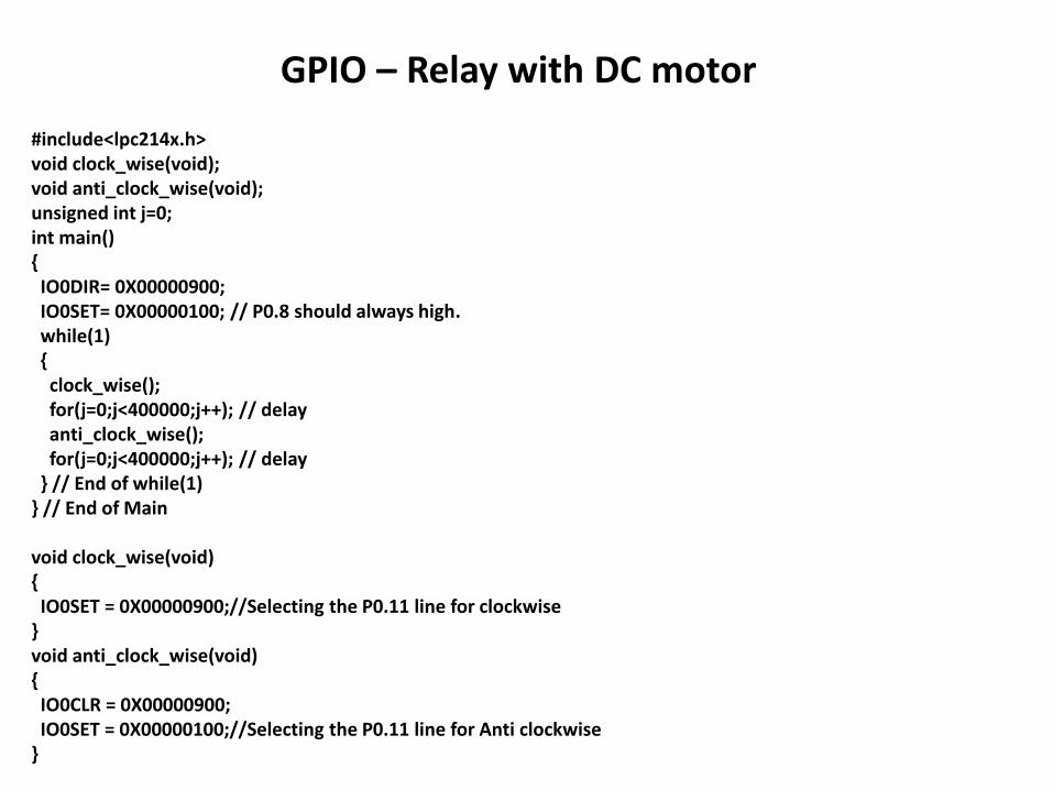
#include<lpc214x.h> void clock_wise(void); void anti_clock_wise(void); unsigned int j=0; int main() { IO0DIR= 0X00000900; IO0SET= 0X00000100; // P0.8 should always high. while(1) { clock_wise(); for(j=0;j<400000;j++); // delay anti_clock_wise(); for(j=0;j<400000;j++); // delay } // End of while(1) } // End of Main void clock_wise(void) { IO0SET = 0X00000900;//Selecting the P0.11 line for clockwise } void anti_clock_wise(void) { IO0CLR = 0X00000900; IO0SET = 0X00000100;//Selecting the P0.11 line for Anti clockwise }
GPIO – Relay with DC motor

#include <LPC21xx.H> void clock_wise(void); void anti_clock_wise(void); unsigned long int var1,var2; unsigned int i=0,j=0,k=0; int main(void) { PINSEL0 = 0x00FFFFFF; //P0.12 to P0.15 GPIo IO0DIR |= 0x0000F000; //P0.12 to P0.15 output while(1) { for(j=0;j<50;j++) // 20 times in Clock wise Rotation clock_wise(); for(k=0;k<65000;k++); // Delay to show anti_clock Rotation for(j=0;j<50;j++) // 20 times in Anti Clock wise Rotation anti_clock_wise(); for(k=0;k<65000;k++); // Delay to show clock Rotation } // End of while(1) } // End of main
GPIO – Stepper motor

void clock_wise(void) { var1 = 0x00000800; //For Clockwise for(i=0;i<=3;i++) // for A B C D Stepping { var1 = var1<<1; //For Clockwise IO0PIN = ~var1; for(k=0;k<3000;k++); //for step speed variation } } void anti_clock_wise(void) { var1 = 0x00010000; //For Anticlockwise for(i=0;i<=3;i++) // for A B C D Stepping { var1 = var1>>1; //For Anticlockwise IO0PIN = ~var1; for(k=0;k<3000;k++); //for step speed variation } }
GPIO – Stepper motor