ardupilot vsm user guide - ugcs more than one ardupilot vehicle is planned to be used with ugcs, ......
TRANSCRIPT
Ardupilot VSM User GuideUgCS 2.13.401
Copyright © 2017, SPH Engineering
ii CONTENTS
Contents
1 Connecting Ardupilot autopilot to UgCS 1
1.1 First time vehicle connection . . . . . . . . . . . . . . . . . . . . . . . . . . . . . . . . . . . . . 1
1.2 Mission execution specifics . . . . . . . . . . . . . . . . . . . . . . . . . . . . . . . . . . . . . . 3
1.3 Altitude . . . . . . . . . . . . . . . . . . . . . . . . . . . . . . . . . . . . . . . . . . . . . . . . 3
1.4 Home Location . . . . . . . . . . . . . . . . . . . . . . . . . . . . . . . . . . . . . . . . . . . . 3
1.4.1 Landing at Home Location . . . . . . . . . . . . . . . . . . . . . . . . . . . . . . . . . . 4
1.5 Command execution specifics . . . . . . . . . . . . . . . . . . . . . . . . . . . . . . . . . . . . . 4
1.6 Joystick support . . . . . . . . . . . . . . . . . . . . . . . . . . . . . . . . . . . . . . . . . . . . 5
1.7 Command shading . . . . . . . . . . . . . . . . . . . . . . . . . . . . . . . . . . . . . . . . . . 5
1.8 Telemetry information specifics . . . . . . . . . . . . . . . . . . . . . . . . . . . . . . . . . . . . 5
1.8.1 Air speed . . . . . . . . . . . . . . . . . . . . . . . . . . . . . . . . . . . . . . . . . . . 5
1.8.2 RC link quality . . . . . . . . . . . . . . . . . . . . . . . . . . . . . . . . . . . . . . . . . 6
1.9 Fail-safe actions . . . . . . . . . . . . . . . . . . . . . . . . . . . . . . . . . . . . . . . . . . . . 6
1.10 Waypoint turn types . . . . . . . . . . . . . . . . . . . . . . . . . . . . . . . . . . . . . . . . . . 6
1.11 Connection using ZigBee interface . . . . . . . . . . . . . . . . . . . . . . . . . . . . . . . . . . 7
1.12 Configuration file . . . . . . . . . . . . . . . . . . . . . . . . . . . . . . . . . . . . . . . . . . . 8
1.12.1 Common parameters . . . . . . . . . . . . . . . . . . . . . . . . . . . . . . . . . . . . . 8
1.12.2 Communication channel configuration . . . . . . . . . . . . . . . . . . . . . . . . . . . . 8
1.12.3 Model name and serial number override . . . . . . . . . . . . . . . . . . . . . . . . . . . 8
1.12.4 Camera control parameters . . . . . . . . . . . . . . . . . . . . . . . . . . . . . . . . . . 9
1.12.5 Joystick control parameters . . . . . . . . . . . . . . . . . . . . . . . . . . . . . . . . . . 9
1.12.6 Report relative altitude . . . . . . . . . . . . . . . . . . . . . . . . . . . . . . . . . . . . 9
1.12.7 Telemetry rate configuration . . . . . . . . . . . . . . . . . . . . . . . . . . . . . . . . . 10
1.12.8 DISARM_DELAY parameter . . . . . . . . . . . . . . . . . . . . . . . . . . . . . . . . . 10
1.13 Common configuration file parameters . . . . . . . . . . . . . . . . . . . . . . . . . . . . . . . . 10
1.13.1 UgCS server configuration . . . . . . . . . . . . . . . . . . . . . . . . . . . . . . . . . . 10
1.13.2 Automatic service discovery . . . . . . . . . . . . . . . . . . . . . . . . . . . . . . . . . 11
1.13.3 Logging configuration . . . . . . . . . . . . . . . . . . . . . . . . . . . . . . . . . . . . . 12
1.13.4 Mission dump path . . . . . . . . . . . . . . . . . . . . . . . . . . . . . . . . . . . . . . 13
1.14 Command execution control . . . . . . . . . . . . . . . . . . . . . . . . . . . . . . . . . . . . . . 13
1.14.1 Command try count . . . . . . . . . . . . . . . . . . . . . . . . . . . . . . . . . . . . . . 13
1.14.2 Command timeout . . . . . . . . . . . . . . . . . . . . . . . . . . . . . . . . . . . . . . 13
1.15 Communication with vehicle . . . . . . . . . . . . . . . . . . . . . . . . . . . . . . . . . . . . . . 13
1.15.1 Serial port configuration . . . . . . . . . . . . . . . . . . . . . . . . . . . . . . . . . . . 14
1.15.2 Outgoing TCP connection configuration . . . . . . . . . . . . . . . . . . . . . . . . . . . 15
1.15.3 Incoming TCP connection configuration . . . . . . . . . . . . . . . . . . . . . . . . . . . 15
1.15.4 Outgoing UDP connection configuration . . . . . . . . . . . . . . . . . . . . . . . . . . . 16
1.15.5 Incoming UDP connection configuration . . . . . . . . . . . . . . . . . . . . . . . . . . . 17
Copyright © 2017, SPH Engineering

CONTENTS iii
1.15.6 Incoming UDP connection configuration (any peer) . . . . . . . . . . . . . . . . . . . . . 17
1.15.7 Proxy configuration . . . . . . . . . . . . . . . . . . . . . . . . . . . . . . . . . . . . . . 17
2 Disclaimer 18
Copyright © 2017, SPH Engineering

1 Connecting Ardupilot autopilot to UgCS 1
1 Connecting Ardupilot autopilot to UgCS
1.1 First time vehicle connection
See Disclaimer.
Please follow these steps to connect an Ardupilot vehicle to the UgCS:
1. Ardupilot vehicle must be properly configured, calibrated and tested using tools and instruction from theofficial Ardupilot web site prior to using it with UgCS. UgCS does not support initial configuration,setup and calibration of Ardupilot driven vehicles.
2. If more than one Ardupilot vehicle is planned to be used with UgCS, it must be ensured that each vehiclehas a unique system id as defined by the parameter SYSID_THISMAV, otherwise UgCS will not be able todistinguish between different vehicles and it will not be possible to operate vehicles normally. To change theparameter, please use the official Ardupilot configuration software like Mission Planner.
3. Turn on the vehicle and plug in the radio modem paired with the vehicle or direct USB cable from the Ardupi-lot board to the computer where VSM is running. UgCS uses serial ports for communication with Ardupilotvehicles. Standard communication devices like 3DR radio modems (and their analogs) and direct USB con-nections are supported, as long as OS driver for virtual serial port is installed and serial port is successfullycreated. Please refer to your communication equipment manufacturer documentation about driver installationinstructions.
4. As soon as uplink and downlink connection is established, the vehicle should appear in the active vehicles listin main (map) view. Open Vehicles window from main menu and choose the corresponding vehicle for editingby clicking on the menu item and selecting Edit button. Now you can select the vehicle profile and change thedefault vehicle name to be convenient for you:
Copyright © 2017, SPH Engineering

2 CONTENTS
Figure 1: New Ardupilot vehicle
Vehicle profile needs to be assigned to allow mission planning with this vehicle. Vehicle avatar should beassigned in vehicle profile to properly see the vehicle location on map.
5. Repeat steps above for each your Ardupilot vehicle.
Supported vehicle types:
• Copters
• Planes
• VTOL
Supported Ardupilot firmware versions:
• 3.0
• 3.1.x
• 3.2.x
• 3.3.x
Supported hardware platforms:
• APM
• Pixhawk
Note
When working with VTOL vehicles make sure the Q_MAV_TYPE correctly.
Copyright © 2017, SPH Engineering
• 3.4x
• 3.5.x

1.2 Mission execution specifics 3
1.2 Mission execution specifics
Note
If one wants to use automatic take-off, it is strongly recommended to place the first waypoint above the actuallocation of the vehicle. Otherwise the vehicle will reach for the first waypoint in a straight line thus possiblycausing danger.
Mission action support:
Flight plan element / action Support NotesChange speed Partial Changing of flight speed during the
mission may work only on latest3.3.x firmware.
Panorama Partial Only clock-wise movement issupported due to Ardupilotfirmware bug. UgCS providescorrect angle values according toMavlink specification.
Set camera mode Partial Only photo mode is supported.Set camera by time Partial "First shot delay" parameter is not
supported.Set camera by distance Partial Only "Distance" parameter is
supported.Set camera attitude NoSet POI YesChange yaw Yes
Camera control
For using camera you should set up necessary parameters in ArduPilot native software according to your hardwareconfiguration. See also Camera control parameters
• VSM configuration should match your copter configuration. See ArduCopter manual for details.
For example, in MissionPlanner the camera set up can be done in "Initial setup" page "Optional hardware/Cameragimbal/Shutter" section. Select the channel your shutter is connected to and set other parameters depending onyour shutter control hardware.
1.3 Altitude
Ardupilot reports two altitude types - AMSL (Above Mean Sea Level) and AHL (Above Home Location). UgCS isusing only the reported AMSL altitude. In previous versions altitude AHL from Adrupilot was reported as RAWaltitude. It was decided not to show altitude AHL as RAW because it would be inconsistent with other supportedautopilots. Altitude AHL will be added in future versions of UgCS.
Current altitude AGL (Above Ground Level) is calculated as:
Vehicle altitude AGL = Reported vehicle altitude AMSL - Terrain elevation AMSL at vehicle location
1.4 Home Location
Home location support differs depending on ArduPilot firmware.
ArduCopter firmware version up to 3.2.1
Copyright © 2017, SPH Engineering

4 CONTENTS
Warning
Home location set via mission is ignored by Ardupilot firmware version 3.2.1.
Ardupilot will always override home location with current position at the time of arming.
When "RETURN_HOME" command is issued from UgCS Client or RC transmitter, vehicle will return to the locationit was armed at regardless of home location set in mission.
ArduCopter firmware version 3.3.1 and up
Mission upload automatically sets Home location. There are several restrictions on Home location:
• Home location can be set only while enough GPS satellites are visible.
• Home location should be close to current location (within 50km)
Mission will fail to upload if any of the above conditions do not hold.
Note
Home location altitude is always 0m AGL (Above Ground Level). I.e. Vehicle must be launched from theground level. This is a limitation of UgCS software and will be removed in future versions.
1.4.1 Landing at Home Location
Vehicle behavior after returning at Home Location depends on on the configuration parameter RTL_ALT_FINAL:
• RTL_ALT_FINAL == 0: Vehicle will land automatically
• RTL_ALT_FINAL > 0: Vehicle will descend to given altitude (in centimeters) and hover there waiting for usercontrol.
Note
RTL_ALT_FINAL parameter can be set using MissionPlanner software.
1.5 Command execution specifics
Command Support NotesARM Yes Arms vehicle.DISARM Yes Disarms vehicle. For copter this
works only when vehicle is on theground.
AUTOMODE Yes Start mission from first waypoint.Sets vehicle into Auto flight mode.
MANUALMODE Yes Sets Manual mode. It’s LOITERfor multicopter frames andSTABILIZE for fixed wing.
CLICK & GO Yes Sets Click & Go (single waypoint)mode.
JOYSTICK Yes Sets Joystick mode. See alsoJoystick support below.
Copyright © 2017, SPH Engineering

1.6 Joystick support 5
HOLD Yes Pause mission execution. Thedrone will loiter at its currentposition.
CONTINUE Yes Continue with mission executionfrom next waypoint. Works fromManual, Joystick_ and Click&Gomodes.
RETURN HOME Yes Vehicle will return to homelocation. See also Home Location.
TAKEOFF NoLAND YesEMERGENCYLAND NoCAMERA_TRIGGER No
1.6 Joystick support
Ardupilot can be put into Joystick mode which allows user to manually control the vehicle in similar way to RCtransmitter. Please note that Joystick mode is inherently more fragile than direct manual control via RC transmitterbecause it involves many different data links and components:
Joystick device –> UgCS client –> server –> VSM –> Ground Radio –> Air Radio –> Autopilot
If any of the above links fail, the joystick control is broken and vehicle automatically goes into manual mode. (Loiterfor copters and Stabilize for planes) This is why user should be very careful when working with Joystick controlmode. It is recommended to have RC transmitter as backup controller.
Note
One specific Ardupilot firmware version 3.4.3 does not support Joystick mode.Joystick control mode is disabled by default for fixed wing frames. To enable Joystick mode for planes pleaserefer to section Joystick control parameters.
1.7 Command shading
UGCS Client can show command buttons in different shades. You can always press all buttons disregarding ofshade. Highlighted buttons suggest recommended commands, depending on vehicle current status.
Command shading
State Button highlighted Button shadedArmed DISARM, AUTOMODE,
MANUALMODE, LAND,RETURNHOME, CLICK-GO,JOYSTICK, HOLD, CONTINUE
ARM
Disarmed ARM DISARM, AUTOMODE,MANUALMODE, LAND,RETURNHOME, CLICK-GO,JOYSTICK, HOLD, CONTINUE
1.8 Telemetry information specifics
1.8.1 Air speed
If there is no air speed sensor onboard, air speed will be shown as "Not available". If there is an air speed sensoronboard, the air speed value will be shown.
Copyright © 2017, SPH Engineering
6 CONTENTS
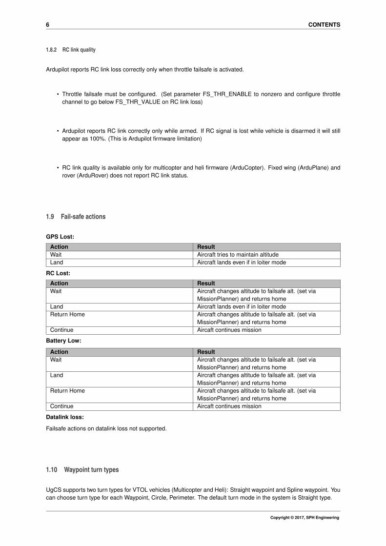
1.8.2 RC link quality
Ardupilot reports RC link loss correctly only when throttle failsafe is activated.
• Throttle failsafe must be configured. (Set parameter FS_THR_ENABLE to nonzero and configure throttlechannel to go below FS_THR_VALUE on RC link loss)
• Ardupilot reports RC link correctly only while armed. If RC signal is lost while vehicle is disarmed it will stillappear as 100%. (This is Ardupilot firmware limitation)
• RC link quality is available only for multicopter and heli firmware (ArduCopter). Fixed wing (ArduPlane) androver (ArduRover) does not report RC link status.
1.9 Fail-safe actions
GPS Lost:
Action ResultWait Aircraft tries to maintain altitudeLand Aircraft lands even if in loiter mode
RC Lost:
Action ResultWait Aircraft changes altitude to failsafe alt. (set via
MissionPlanner) and returns homeLand Aircraft lands even if in loiter modeReturn Home Aircraft changes altitude to failsafe alt. (set via
MissionPlanner) and returns homeContinue Aircaft continues mission
Battery Low:
Action ResultWait Aircraft changes altitude to failsafe alt. (set via
MissionPlanner) and returns homeLand Aircraft changes altitude to failsafe alt. (set via
MissionPlanner) and returns homeReturn Home Aircraft changes altitude to failsafe alt. (set via
MissionPlanner) and returns homeContinue Aircaft continues mission
Datalink loss:
Failsafe actions on datalink loss not supported.
1.10 Waypoint turn types
UgCS supports two turn types for VTOL vehicles (Multicopter and Heli): Straight waypoint and Spline waypoint. Youcan choose turn type for each Waypoint, Circle, Perimeter. The default turn mode in the system is Straight type.
Copyright © 2017, SPH Engineering

1.11 Connection using ZigBee interface 7
Figure 2: Turn type
Turn type Support NotesStraight Yes The vehicle will fly a straight line to
the location specified as a lat, lonand altitude.
Spline Yes The vehicle will fly to the locationspecified as a lat, lon and altitude,but when executed the vehicle willfly smooth paths (both verticallyand horizontally) instead of straightlines.
Note
• When using Spline turn type make sure the line segment after the waypoint is long enough otherwiseautopilot can fly unexpectedly missing some waypoints. What is "long enough"? The desired segmentlength varies with speed. Our tests show that with ground speed 5m/s route segment must be at least20m long. If speed is set to 10m/s then route segment after the waypoint should be at least 50 meters.
• Different turn types for fixed wing vehicles are not supported.
You can find more information about turning mode and supporting autopilots on the sites:
• https://github.com/diydrones/apm_planner/issues/274
• http://copter.ardupilot.com/wiki/mission-command-list/#spline_waypoint
1.11 Connection using ZigBee interface
There is a possibility to connect UgCS to Ardupilot vehicle using ZigBee interface. Connection is performed withtwo or more Digi XBee ZigBee modules (one on ground side, others on vehicles side) and dedicated UgCS softwarecomponent called XBee Connector. Please refer to XBee Connector user guide for details.
In order to use such kind of connection you are to disable Serial port configuration and enable Proxy configuration.
Copyright © 2017, SPH Engineering

8 CONTENTS
1.12 Configuration file
Default configuration file of the Ardupilot VSM suits most needs and it is generally not necessary to modify it.
Configuration file location:
• On Microsoft Windows:
C:\Program Files (x86)\UgCS\bin\vsm-ardupilot.conf
• On GNU/Linux:
/etc/opt/ugcs/vsm-ardupilot.conf
• On Apple OS X:
/Users/[user name]/Library/Application Support/UGCS/configuration/vsm-ardupilot.conf
1.12.1 Common parameters
All VSMs share a common set of configuration file parameters described in Common configuration file parameters.Ardupilot VSM configuration file prefix is:
vehicle.ardupilot
1.12.2 Communication channel configuration
There must be at least one communication channel defined, otherwise VSM will not try to connect to the vehicle.See Communication with vehicle for details
Default installation is configured to detect autopilot automatically on any available serial port at 57600 or 115Kbps.
1.12.3 Model name and serial number override
Optional.
• Name: vehicle.ardupilot.custom.[name].system_id = [system id]
• Name: vehicle.ardupilot.custom.[name].model_name = [model name]
• Name: vehicle.ardupilot.custom.[name].serial_number = [serial number]
• Description: In UgCS each vehicle is identified by a unique combination of model name and serial numberrepresented as text strings. By default, Ardupilot vehicles are identified with a model name Ardupilot and serialnumber equal with the Mavlink system id read from the vehicle. It can be overridden by these parameters,where [name] is an arbitrary vehicle name, [system id] is the original Mavlink system id which should beoverridden, [model name] is a new model name to be visible to the UgCS, [serial number] is a new serialnumber to be visible to the UgCS.
• Example:
vehicle.ardupilot.custom.my_drone.system_id = 2vehicle.ardupilot.custom.my_drone.model_name = ArducopterQuadvehicle.ardupilot.custom.my_drone.serial_number = 123456
Copyright © 2017, SPH Engineering
1.12 Configuration file 9
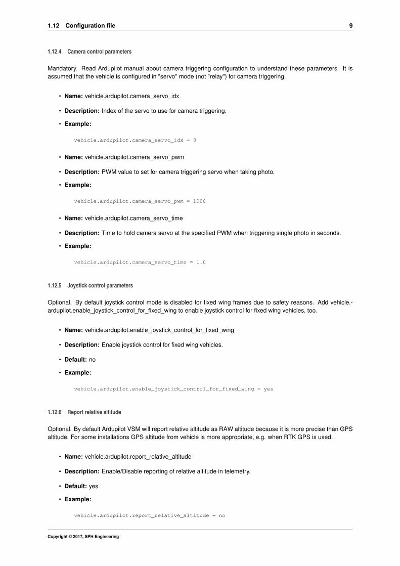
1.12.4 Camera control parameters
Mandatory. Read Ardupilot manual about camera triggering configuration to understand these parameters. It isassumed that the vehicle is configured in "servo" mode (not "relay") for camera triggering.
• Name: vehicle.ardupilot.camera_servo_idx
• Description: Index of the servo to use for camera triggering.
• Example:
vehicle.ardupilot.camera_servo_idx = 8
• Name: vehicle.ardupilot.camera_servo_pwm
• Description: PWM value to set for camera triggering servo when taking photo.
• Example:
vehicle.ardupilot.camera_servo_pwm = 1900
• Name: vehicle.ardupilot.camera_servo_time
• Description: Time to hold camera servo at the specified PWM when triggering single photo in seconds.
• Example:
vehicle.ardupilot.camera_servo_time = 1.0
1.12.5 Joystick control parameters
Optional. By default joystick control mode is disabled for fixed wing frames due to safety reasons. Add vehicle.-ardupilot.enable_joystick_control_for_fixed_wing to enable joystick control for fixed wing vehicles, too.
• Name: vehicle.ardupilot.enable_joystick_control_for_fixed_wing
• Description: Enable joystick control for fixed wing vehicles.
• Default: no
• Example:
vehicle.ardupilot.enable_joystick_control_for_fixed_wing = yes
1.12.6 Report relative altitude
Optional. By default Ardupilot VSM will report relative altitude as RAW altitude because it is more precise than GPSaltitude. For some installations GPS altitude from vehicle is more appropriate, e.g. when RTK GPS is used.
• Name: vehicle.ardupilot.report_relative_altitude
• Description: Enable/Disable reporting of relative altitude in telemetry.
• Default: yes
• Example:
vehicle.ardupilot.report_relative_altitude = no
Copyright © 2017, SPH Engineering
10 CONTENTS
1.12.7 Telemetry rate configuration
Ardupilot VSM supports setting custom telemetry rate to manage datalink channel bandwidth. Rate of 1 produces∼350 bytes/sec of telemetry traffic. 56K radiolink in ideal conditions can sustain the telemetry_rate = 5. Highertelemetry rates are not recommended and should be tried only with fast datalinks.
• Required: No.
• Supported values: 1 - 50
• Default: 2
• Description: Set update fequency for vehicle state information (attitude, position, battery, etc...)
• Example:
vehicle.ardupilot.telemetry_rate = 1
1.12.8 DISARM_DELAY parameter
• Required: No.
• Supported values: 0 - 127
• Default: Do not set
• Description: Configure the delay after which vehicle automatically disarms if on the ground. 0 - disable thedisarm timer.
• Example:
vehicle.ardupilot.parameter.DISARM_DELAY = 5
1.13 Common configuration file parameters
VSM configuration file is a text file specified via command line argument - -config of the VSM application. Example:
--config /etc/opt/ugcs/vsm-ardupilot.conf
Each configuration parameter is defined as a line in the configuration file with the following structure:
name1.name2....nameX = value
where name1, name2 ... nameX are arbitrary names separated by dots to divide a variable into logical blocks anda value which can be a number value or a text string depending on the context. See below the description aboutcommon VSM configuration parameters.
1.13.1 UgCS server configuration
VSM can connect to UgCS in two different ways:
• Listen for connection form the UgCS server. See Listening address and Listening port.
When VSM is configured in listening mode automatic VSM discovery can be set up, too. See Automaticservice discovery
• Initiate connection to UgCS server. See UgCS server address and UgCS server port.
At least one of the above must be configured for VSM to work.
Copyright © 2017, SPH Engineering
1.13 Common configuration file parameters 11
1.13.1.1 Listening address
Optional.
• Name: ucs.local_listening_address = [IP address]
• Description: Local address to listen for incoming connections from UgCS server.
• Default: 0.0.0.0 (listen on all local addresses)
• Example: ucs.local_listening_address = 10.0.0.2
1.13.1.2 Listening port
Optional.
• Name: ucs.local_listening_port = [port number]
• Description: Local TCP port to listen for incoming connections from UgCS server. Default is 5556.
• Example: ucs.local_listening_port = 5556
1.13.1.3 UgCS server address
Optional.
• Name: ucs.address = [IP address]
• Description: UgCS server address to connect to.
• Example: ucs.address = 1.2.3.4
1.13.1.4 UgCS server port
Optional.
• Name: ucs.port = [port number]
• Description: UgCS server port.
• Example: ucs.port = 3335
1.13.1.5 Retry timeout
Optional.
• Name: ucs.retry_timeout = [seconds]
• Description: Retry timeout for outgoing server connections in seconds.
• Default: 10
• Example: retry_timeout = 11
1.13.2 Automatic service discovery
VSM can respond to automatic service discovery requests form UgCS server.
When this parameter is not configured, service discovery is disabled.
Optional.
• Name: service_discovery.vsm_name = [Service name]
• Description: Human readable service name.
• Example: service_discovery.vsm_name = Ardupilot VSM
Copyright © 2017, SPH Engineering
12 CONTENTS
1.13.3 Logging configuration
1.13.3.1 Level
Optional.
• Name: log.level = [error|warning|info|debug]
• Description: Logging level.
• Default: info
• Example: log.level = debug
1.13.3.2 File path
Optional.
• Name: log.file_path = [path to a file]
• Description: Absolute or relative (to the current directory) path to a logging file. Logging is disabled if loggingfile is not defined. File should be writable. Backslash should be escaped with a backslash.
• Example: log.file = /var/opt/ugcs/log/vsm-ardupilot/vsm-ardupilot.log
• Example: log.file = C:\\Users\\John\\AppData\\Local\\UGCS\\logs\\vsm-ardupilot\\vsm-ardupilot.log
1.13.3.3 Maximum single file size
Optional.
• Name: log.single_max_size = [size]
• Description: Maximum size of a single log file. When maximum size is exceeded, existing file is renamedby adding a time stamp and logging is continued into the empty file. [size] should be defined as a numberpostfixed by a case insensitive multiplier:
– Gb, G, Gbyte, Gbytes: for Giga-bytes
– Mb, M, Mbyte, Mbytes: for Mega-bytes
– Kb, K, Kbyte, Kbytes: for Kilo-bytes
– no postfix: for bytes
• Default: 100 Mb
• Example: log.single_max_size = 500 Mb
1.13.3.4 Maximum number of old log files
Optional.
• Name: log.max_file_count = [number]
• Description: Log rotation feature. Maximum number of old log files to keep. After reaching single_max_sizeof current log file VSM will rename it with current time in extension and start new one. VSM will delete olderlogs so the number of old logs does not exceed the max_file_count.
• Default: 1
• Example: log.max_file_count = 5
Copyright © 2017, SPH Engineering

1.14 Command execution control 13
1.13.4 Mission dump path
Optional.
• Name: [prefix].mission_dump_path = [path to a file]
• Description: File to dump all generated missions to. Timestamp is appended to the name. Delete the entryto disable mission dumping. All directories in the path to a file should be already created.
• Example: vehicle.ardupilot.mission_dump_path = C:\\tmp\\ardupilot_dump
1.14 Command execution control
When vehicle is connected via unreliable link VSM will retry each command several times before failing. This sectiondescribes the parameters which control the command execution.
1.14.1 Command try count
• Name: vechicle.command_try_count = <number of="" times>="">
• Description: Number of times the command will be issued before declaring it as failed. Must be greater thanzero.
• Default: 3
• Example: vechicle.command_try_count = 5
1.14.2 Command timeout
• Name: vechicle.command_timeout = <timeout in="" seconds>="">
• Description: Time to wait for response on issued command before retrying.
• Unit: second
• Default: 1
• Example: vechicle.command_timeout = 3.14
1.15 Communication with vehicle
VSM can communicate with Vehicle over different communication channels
Currently supported channels:
• Serial port, see Serial port configuration for details.
• Outgoing TCP, see Outgoing TCP connection configuration for details.
• Incoming TCP, see Incoming TCP connection configuration for details.
• Outgoing UDP, see Outgoing UDP connection configuration for details.
• Incoming UDP, see Incoming UDP connection configuration for details.
• vsm-proxy (XBee), see Proxy configuration for details.
Copyright © 2017, SPH Engineering

14 CONTENTS
1.15.1 Serial port configuration
VSM which communicates with vehicles via serial ports should define at least one serial port, otherwise VSM willnot try to connect to the vehicles. Port name and baud rate should be both defined.
1.15.1.1 Port name
Required.
• Name: connection.serial.[index].name = [regular expression]
• Description: Ports which should be used to connect to the vehicles by given VSM. Port names are definedby a [regular expression] which can be used to define just a single port or create a port filtering regularexpression. Expression is case insensitive on Windows. [index] is a arbitrary port indexing name.
• Example: connection.serial.1.name = /dev/ttyUSB[0-9]+|com[0-9]+
• Example: connection.serial.2.name = com42
1.15.1.2 Port baud rate
Required.
• Name: connection.serial.[index].baud.[baud index] = [baud]
• Description: Baud rate for port opening. [baud index] is an optional arbitrary name used when it is necessaryto open the same serial port using multiple baud rates. [index] is an arbitrary port indexing name.
• Example: connection.serial.1.baud.1 = 9600
• Example: connection.serial.1.baud.2 = 57600
• Example: connection.serial.2.baud = 38400
1.15.1.3 Excluded port name
Optional.
• Name: connection.serial.exclude.[exclude index] = [regular expression]
• Description: Ports which should not be used for vehicle access by this VSM. Port names are defined by a[regular expression] which can be used to define just a single port or create a port filtering regular expression.Filter is case insensitive on Windows. [exclude index] is a arbitrary indexing name used when more than oneexclude names are defined.
• Example: connection.serial.exclude.1 = /dev/ttyS.∗
• Example: connection.serial.exclude = com1
1.15.1.4 Serial port arbiter
Optional.
• Name: connection.serial.use_arbiter = [yes|no]
• Description: Enable (yes) or disable (no) serial port access arbitration between VSMs running on the samemachine. It is recommended to have it enabled to avoid situation when multiple VSMs try to open the sameport simultaneously.
• Default: yes
• Example: connection.serial.use_arbiter = no
Copyright © 2017, SPH Engineering

1.15 Communication with vehicle 15
1.15.2 Outgoing TCP connection configuration
VSM can be configured to connect to the vehicle via TCP. VSM will try to establish connection to the specifiedaddress:port.
Used to connect to vehicle simulator or when vehicle is equipped with WiFi adapter.
1.15.2.1 Remote TCP port
Required.
• Name: connection.tcp_out.[index].port = [port number]
• Description: Remote port to connect to.
• Example: connection.tcp_out.1.port = 5762
1.15.2.2 IP-address for outgoing TCP connection
Required.
• Name: connection.tcp_out.[index].address = [IP-address]
• Description: IP-address of vehicle to connect to.
• Example: connection.tcp_out.1.address = 10.0.0.111
1.15.2.3 Retry timeout
Optional.
• Name: connection.tcp_out.[index].retry_timeout = [seconds]
• Description: Time before retrying after connection failure
• Default: 10
• Example: connection.tcp_out.1.retry_timeout = 55
1.15.3 Incoming TCP connection configuration
VSM can be configured to listen for incoming TCP connections from the vehicle. Multiple vehicles are supported onthe same port.
Used to connect to vehicle equipped with WiFi adapter.
1.15.3.1 Local listening TCP port
Required.
• Name: connection.tcp_in.[index].local_port = [port number]
• Description: Remote port to connect to.
• Example: connection.tcp_in.1.local_port = 5762
Copyright © 2017, SPH Engineering

16 CONTENTS
1.15.3.2 Local IP address
Optional.
• Name: connection.tcp_in.[index].local_address = [IP-address]
• Description: Local ip address to bind to.
• Default: 0.0.0.0 (all interfaces)
• Example: connection.tcp_in.1.local_address = 127.0.0.1
1.15.4 Outgoing UDP connection configuration
VSM can be configured to connect to the vehicle via UDP. VSM will try to establish UDP connection to the specifiedaddress:port.
1.15.4.1 Remote IP-address for UDP
Required.
• Name: connection.udp_out.[index].address = [IP-address]
• Description: Remote IP-address to send outgoing UDP packets to.
• Example: connection.udp_out.1.address = 192.168.1.1
1.15.4.2 Remote UDP port
Required.
• Name: connection.udp_out.[index].port = [port number]
• Description: Remote UDP port to send outgoing packets to.
• Example: connection.udp_out.1.port = 14551
1.15.4.3 Local IP-address for UDP
Optional.
• Name: connection.udp_out.[index].local_address = [IP-address]
• Description: Local ip address to bind to.
• Default: 0.0.0.0 (bind to all interfaces)
• Example: connection.udp_out.1.local_address = 0.0.0.0
1.15.4.4 Local UDP port
Optional.
• Name: connection.udp_out.[index].local_port = [port number]
• Description: Local UDP port to listen for incoming packets on.
• Default: 0 (bind to random port)
• Example: connection.udp_out.1.local_port = 14550
Copyright © 2017, SPH Engineering
1.15 Communication with vehicle 17
1.15.5 Incoming UDP connection configuration
VSM can be configured to listen for UDP conncections from the vehicle. Vehicle must be actively sending heart-beat/telemetry on specified UDP port before it can be detected by VSM. VSM will automatically detect multiplevehicles on the same port. This is very useful for "drone swarm" setups as there is no need to specify connector foreach vehicle and no need to know the IP address of each vehicle in advance.
1.15.5.1 Local UDP port
Required.
• Name: connection.udp_in.[index].local_port = [port number]
• Description: Local UDP port to listen for incoming packets on.
• Example: connection.udp_in.1.local_port = 14550
1.15.5.2 Local IP-address for UDP
Optional.
• Name: connection.udp_in.[index].local_address = [IP-address]
• Description: Local ip address to bind to.
• Default: 0.0.0.0 (bind to all interfaces)
• Example: connection.udp_in.1.local_address = 0.0.0.0
1.15.6 Incoming UDP connection configuration (any peer)
This connection type is similar to "udp_in" with the exception that all incoming traffic will be recevied as one stream.It is used for special purpose connections and cannot be used to connect vehicles.
1.15.6.1 Local UDP port
Required.
• Name: connection.udp_any.[index].local_port = [port number]
• Description: Local UDP port to listen for incoming packets on.
• Example: connection.udp_any.1.local_port = 14550
1.15.6.2 Local IP-address for UDP
Optional.
• Name: connection.udp_any.[index].local_address = [IP-address]
• Description: Local ip address to bind to.
• Default: 0.0.0.0 (bind to all interfaces)
• Example: connection.udp_any.1.local_address = 0.0.0.0
1.15.7 Proxy configuration
VSM is able to communicate with vehicle via proxy service which redirects dataflow received from vehicle throughTCP connection to VSM and vice versa using specific protocol. In other words proxy service appears as a routerbetween vehicle and VSM. At the moment there is one implementation of proxy in UgCS called XBee Connectorwhich retranslates data from ZigBee network to respective VSM.
Copyright © 2017, SPH Engineering

18 CONTENTS
1.15.7.1 IP-address for proxy
Required.
• Name: connection.proxy.[index].address = [IP-address]
• Description: IP-address to connect proxy to. Specify local or remote address.
• Example: connection.proxy.1.address = 127.0.0.1
1.15.7.2 TCP port for proxy
Required.
• Name: connection.proxy.[index].port = [port number]
• Description: TCP port to be connected with proxy through. Should be the same as in congiguration on proxyside.
• Example: connection.proxy.1.port = 5566
1.15.7.3 Retry timeout
Optional.
• Name: connection.proxy.[index].retry_timeout = [seconds]
• Description: Time before retrying after connection failure
• Default: 10
• Example: connection.proxy.1.retry_timeout = 55
2 Disclaimer
DISCLAIMER OF WARRANTIES AND LIMITATIONS ON LIABILITY.
(a) SPH ENGINEERING MAKE NO REPRESENTATIONS OR WARRANTIES REGARDING THE ACCURACY ORCOMPLETENESS OF ANY CONTENT OR FUNCTIONALITY OF THE PRODUCT AND ITS DOCUMENTATION.
(b) SPH ENGINEERING DISCLAIM ALL WARRANTIES IN CONNECTION WITH THE PRODUCT, AND WILL NOTBE LIABLE FOR ANY DAMAGE OR LOSS RESULTING FROM YOUR USE OF THE PRODUCT. INCLUDING BUTNOT LIMITED TO INJURY OR DEATH OF USER OR ANY THIRD PERSONS OR DAMAGE TO PROPERTY.
(c) THE SOFTWARE IS SUPPLIED AS IS WITH NO WARRANTIES AND CAN BE USED ONLY AT USERS OWNRISK.
Copyright © 2017, SPH Engineering