arduino basics - estia · arduino basics table of contents ... 3 the hardware side this section...
TRANSCRIPT

1
Arduino basics
Table of Contents 1 Introduction ........................................................................................................................................... 2
2 Useful links ............................................................................................................................................ 2
3 The Hardware side................................................................................................................................. 3
4 The Software side .................................................................................................................................. 4
5 Libraries ................................................................................................................................................. 5
6 Serial communication ............................................................................................................................ 6
6.1 Serial writing example ................................................................................................................... 6
6.2 Serial reading example .................................................................................................................. 7
7 Digital reading / writing ......................................................................................................................... 8
8 Analog reading ....................................................................................................................................... 8
9 Analog writing ....................................................................................................................................... 9
10 Button .................................................................................................................................................. 10
11 LED ....................................................................................................................................................... 11
11.1 Blinking an LED ............................................................................................................................ 12
11.2 Blinking an LED without delay ..................................................................................................... 12
11.3 Fading an LED with PWM ............................................................................................................ 13
12 RGB LED ............................................................................................................................................... 14
13 Buzzer / Speaker .................................................................................................................................. 18
14 Servo motor ......................................................................................................................................... 19
15 DC Motor and Vibrator ........................................................................................................................ 20
16 Temperature sensor ............................................................................................................................ 22
17 Photoresistive sensor .......................................................................................................................... 24
18 Flex sensor ........................................................................................................................................... 25
19 Vibration sensor .................................................................................................................................. 26
20 Force resistive sensor .......................................................................................................................... 28
21 Hall effect sensor (A1321 family) ........................................................................................................ 29
22 Capacitive sensor (MPR121) ................................................................................................................ 30
23 Accelerometer (ADXL345) ................................................................................................................... 32
24 Accelerometer (ADXL311) ................................................................................................................... 36

2
1 Introduction The purpose of this document is to introduce you the “Arduino Uno” board for using it in the workshop.
It explains hardware and software basics of Arduino, and provides some examples on how to use
different kind of sensors and actuators. Each example is very succinct and is accompanied by its source’s
link that will provide you more information.
2 Useful links Reference of Arduino functions: http://arduino.cc/en/Reference/HomePage
Tutorials main page: http://arduino.cc/en/Tutorial/HomePage
Arduino software: http://arduino.cc/en/Main/Software
Fritzing (for designing your circuit): http://fritzing.org

3
3 The Hardware side This section introduces the Arduino Uno board. We will just make a quick tour of the most important
pins, on the edges of the board.
In the POWER section, the main pins are:
Vin can be used as input voltage for an external power source (7-12V). You can supply voltage
through this pin, or, if supplying voltage via the power jack, access it through this pin. You can
also just use the power from the USB connector, which will be of 5V.
3.3V and 5V provide regulated voltage.
RESET: if LOW, resets the board. There is also a reset button on the top-left edge of the board.
GND are the three ground pins (there is one in the DIGITAL section).
The DIGITAL section is composed of 14 digital pins that can be individually configured as inputs or
outputs. They operate at 5 volts. Some of them have specialized functions:
0 (RX) and 1 (TX) can be used for serial communication.
2 and 3 can be configured to trigger an interrupt (see attachInterrupt() function).
10 (SS), 11 (MOSI), 12 (MISO), 13 (SCK) can be used for SPI communication.
3, 5, 6, 9, 10, and 11 provide 8-bit PWM output (see section 9).
13 is connected to a built-in LED. When the pin is HIGH, the LED is on and when the pin is LOW,
well...
Finally, the ANALOG IN section contains 6 analog inputs working from 0 to 5 volts.
A4 (SDA) and A5 (SCL) also support TWI (or I2C) communication.
4
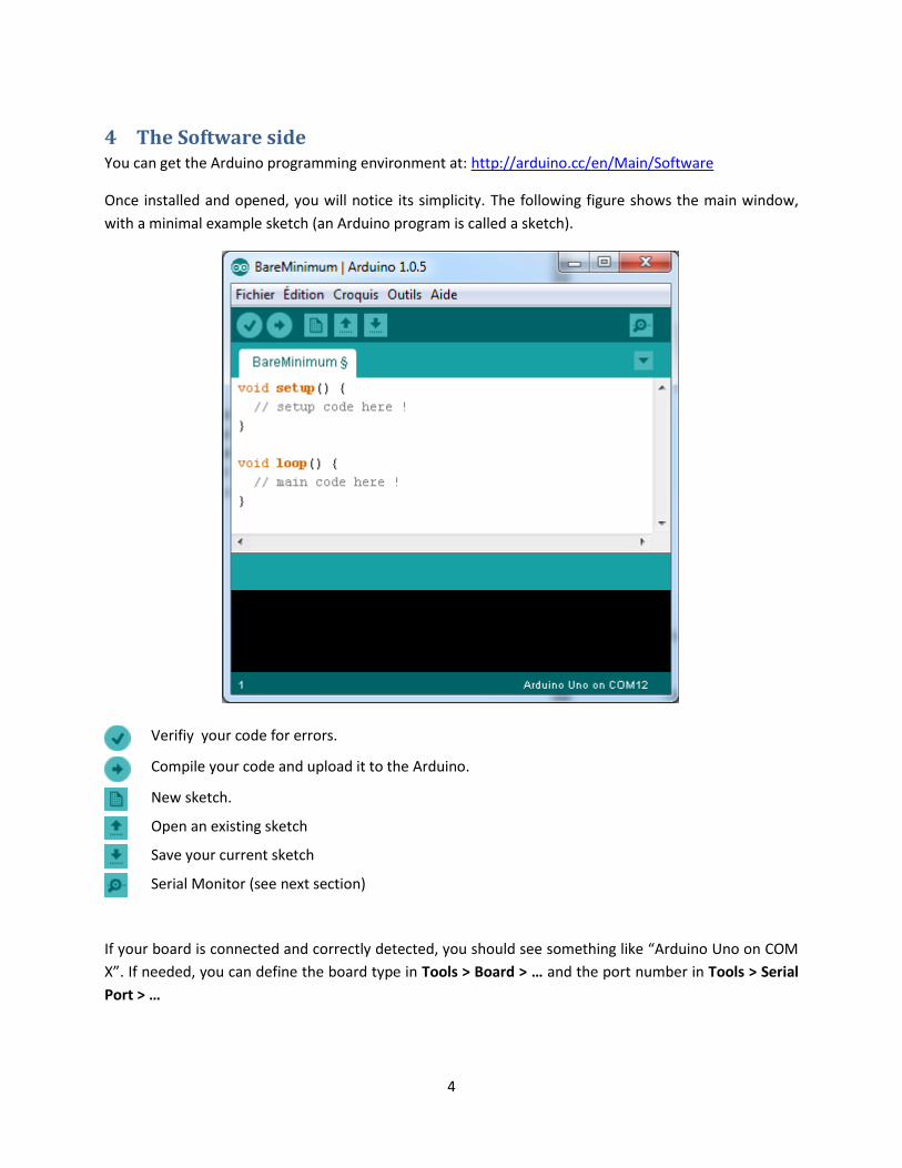
4 The Software side You can get the Arduino programming environment at: http://arduino.cc/en/Main/Software
Once installed and opened, you will notice its simplicity. The following figure shows the main window,
with a minimal example sketch (an Arduino program is called a sketch).
Verifiy your code for errors.
Compile your code and upload it to the Arduino.
New sketch.
Open an existing sketch
Save your current sketch
Serial Monitor (see next section)
If your board is connected and correctly detected, you should see something like “Arduino Uno on COM
X”. If needed, you can define the board type in Tools > Board > … and the port number in Tools > Serial
Port > …

5
5 Libraries An Arduino library is composed of a folder containing a .h file with the name of the library and
sometimes an “examples” folder. To install a library, just unzip it in the “Arduino/libraries” directory (e.g.
C:\Program Files (x86)\Arduino\libraries). For instance, for the “LiquidCrystal” library, the structure you
obtain looks like this:
Arduino
o Libraries
LiquidCrystal
LiquidCrystal.cpp
LiquidCrystal.h
examples
o Blink
o Cursor
o …
Restart your Arduino software and you should be able to see the new library in the “Sketch > Import
Library…” menu, as well as some examples in the “File > Examples” menu. The Import Library menu
automatically includes necessary header files for using the library.
6
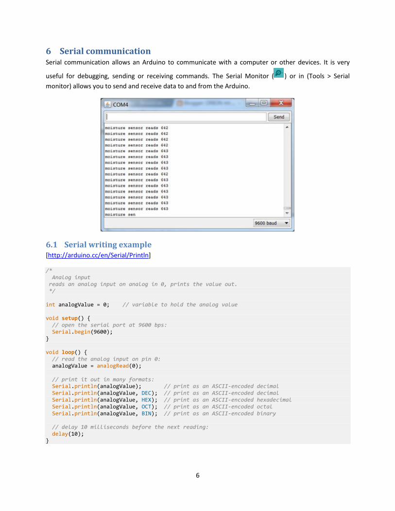
6 Serial communication Serial communication allows an Arduino to communicate with a computer or other devices. It is very
useful for debugging, sending or receiving commands. The Serial Monitor ( ) or in (Tools > Serial
monitor) allows you to send and receive data to and from the Arduino.
6.1 Serial writing example [http://arduino.cc/en/Serial/Println]
/* Analog input reads an analog input on analog in 0, prints the value out. */ int analogValue = 0; // variable to hold the analog value void setup() { // open the serial port at 9600 bps: Serial.begin(9600); } void loop() { // read the analog input on pin 0: analogValue = analogRead(0); // print it out in many formats: Serial.println(analogValue); // print as an ASCII-encoded decimal Serial.println(analogValue, DEC); // print as an ASCII-encoded decimal Serial.println(analogValue, HEX); // print as an ASCII-encoded hexadecimal Serial.println(analogValue, OCT); // print as an ASCII-encoded octal Serial.println(analogValue, BIN); // print as an ASCII-encoded binary // delay 10 milliseconds before the next reading: delay(10); }
7
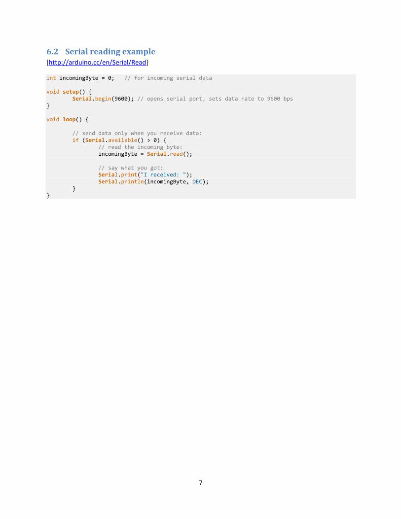
6.2 Serial reading example [http://arduino.cc/en/Serial/Read]
int incomingByte = 0; // for incoming serial data void setup() { Serial.begin(9600); // opens serial port, sets data rate to 9600 bps } void loop() { // send data only when you receive data: if (Serial.available() > 0) { // read the incoming byte: incomingByte = Serial.read(); // say what you got: Serial.print("I received: "); Serial.println(incomingByte, DEC); } }
8
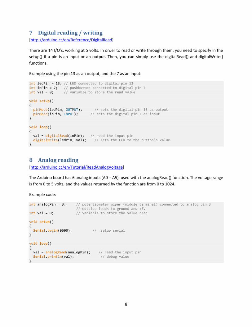
7 Digital reading / writing [http://arduino.cc/en/Reference/DigitalRead]
There are 14 I/O’s, working at 5 volts. In order to read or write through them, you need to specify in the
setup() if a pin is an input or an output. Then, you can simply use the digitalRead() and digitalWrite()
functions.
Example using the pin 13 as an output, and the 7 as an input:
int ledPin = 13; // LED connected to digital pin 13 int inPin = 7; // pushbutton connected to digital pin 7 int val = 0; // variable to store the read value void setup() { pinMode(ledPin, OUTPUT); // sets the digital pin 13 as output pinMode(inPin, INPUT); // sets the digital pin 7 as input } void loop() { val = digitalRead(inPin); // read the input pin digitalWrite(ledPin, val); // sets the LED to the button's value }
8 Analog reading [http://arduino.cc/en/Tutorial/ReadAnalogVoltage]
The Arduino board has 6 analog inputs (A0 – A5), used with the analogRead() function. The voltage range
is from 0 to 5 volts, and the values returned by the function are from 0 to 1024.
Example code:
int analogPin = 3; // potentiometer wiper (middle terminal) connected to analog pin 3 // outside leads to ground and +5V int val = 0; // variable to store the value read void setup() { Serial.begin(9600); // setup serial } void loop() { val = analogRead(analogPin); // read the input pin Serial.println(val); // debug value }

9
9 Analog writing [http://arduino.cc/en/Tutorial/PWM]
[http://arduino.cc/en/Reference/AnalogWrite]
Most Arduinos do not have true analog outputs, but use PWM (Pulse Width Modulation) instead. PWM
is a technique for getting an analog-like behavior from a digital output by switching it off and on very
fast. This on-off pattern can simulate voltages in between full on (5 volts) and off (0 volts) by changing
the portion of the time the signal spends on versus the time that the signal spends off (see the figure
below). This can be used for controlling a motor speed, the brightness of an LED,… and so on. PWM
outputs are the digital I/O’s 3, 5, 6, 9, 10, and 11, and are noticeable by a small ~ sign. To write on a
PWM output, use the analogWrite(pin, value) function. The range of the value is (0-255).
The following example code sets the output to the LED proportional to the value read from the
potentiometer. Since analog input are in range (0-1023) and PWM output are (0-255), the value need to
be divided by 4. If you need such ranges-mapping, you can also use the very useful map() function.
int ledPin = 9; // LED connected to digital pin 9 int analogPin = 3; // potentiometer connected to analog pin 3 int val = 0; // variable to store the read value void setup(){ pinMode(ledPin, OUTPUT); // sets the pin as output } void loop(){ val = analogRead(analogPin); // read the input pin analogWrite(ledPin, val / 4); // map analogin to analogout range }
10
Practical examples
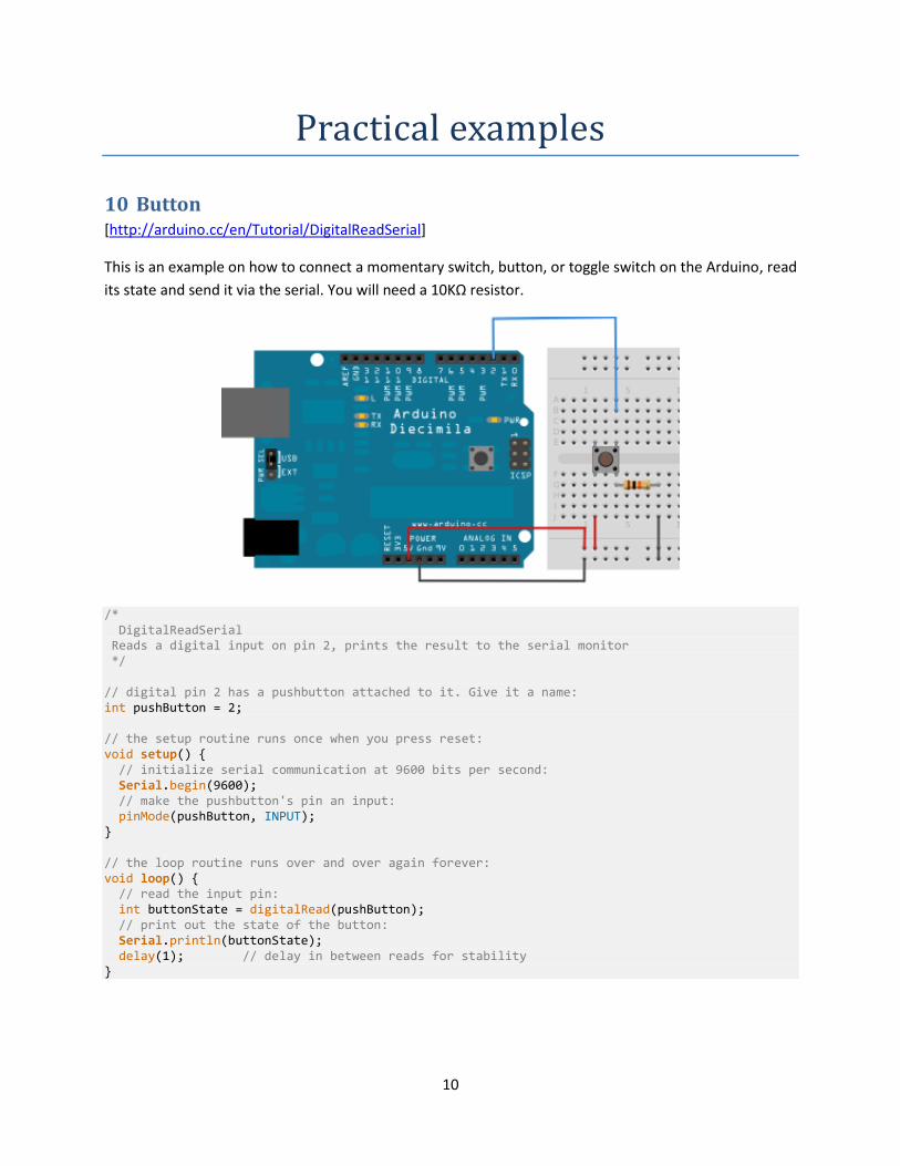
10 Button [http://arduino.cc/en/Tutorial/DigitalReadSerial]
This is an example on how to connect a momentary switch, button, or toggle switch on the Arduino, read
its state and send it via the serial. You will need a 10KΩ resistor.
/* DigitalReadSerial Reads a digital input on pin 2, prints the result to the serial monitor */ // digital pin 2 has a pushbutton attached to it. Give it a name: int pushButton = 2; // the setup routine runs once when you press reset: void setup() { // initialize serial communication at 9600 bits per second: Serial.begin(9600); // make the pushbutton's pin an input: pinMode(pushButton, INPUT); } // the loop routine runs over and over again forever: void loop() { // read the input pin: int buttonState = digitalRead(pushButton); // print out the state of the button: Serial.println(buttonState); delay(1); // delay in between reads for stability }
11
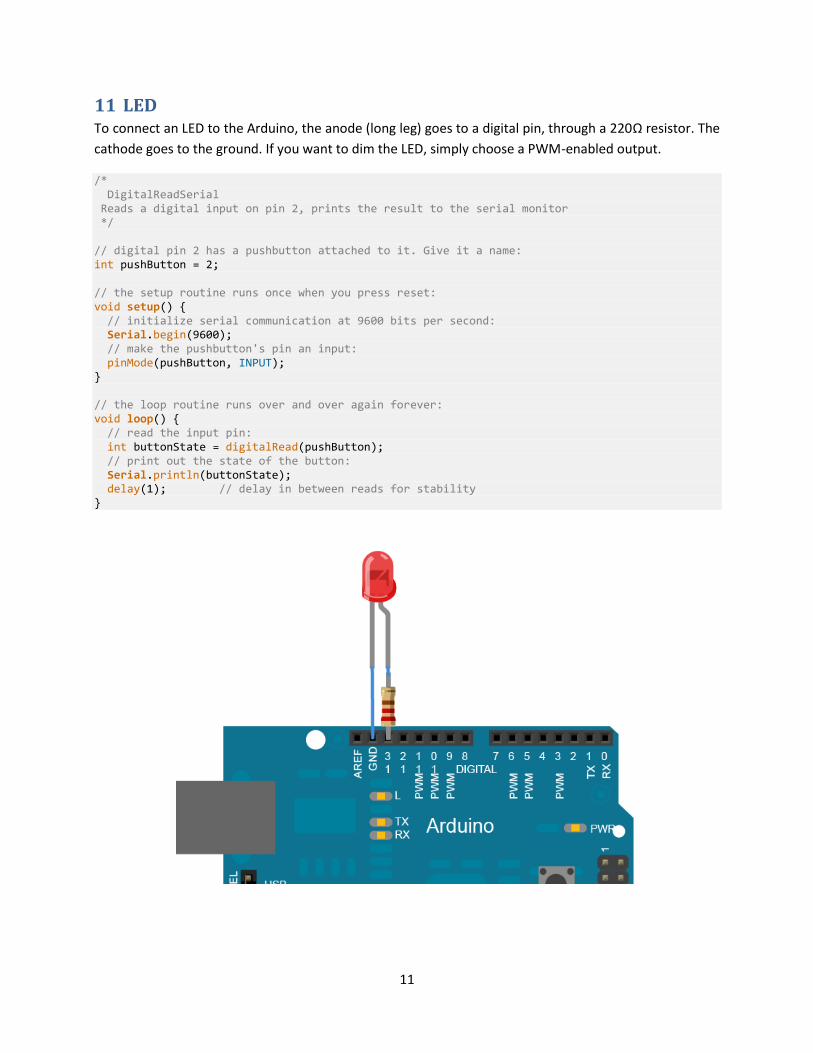
11 LED To connect an LED to the Arduino, the anode (long leg) goes to a digital pin, through a 220Ω resistor. The
cathode goes to the ground. If you want to dim the LED, simply choose a PWM-enabled output.
/* DigitalReadSerial Reads a digital input on pin 2, prints the result to the serial monitor */ // digital pin 2 has a pushbutton attached to it. Give it a name: int pushButton = 2; // the setup routine runs once when you press reset: void setup() { // initialize serial communication at 9600 bits per second: Serial.begin(9600); // make the pushbutton's pin an input: pinMode(pushButton, INPUT); } // the loop routine runs over and over again forever: void loop() { // read the input pin: int buttonState = digitalRead(pushButton); // print out the state of the button: Serial.println(buttonState); delay(1); // delay in between reads for stability }

12
11.1 Blinking an LED [http://arduino.cc/en/Tutorial/Blink]
int led = 13; // Pin 13 has an LED connected on most Arduino boards. void setup() { pinMode(led, OUTPUT); // initialize the digital pin as an output. } // the loop routine runs over and over again forever: void loop() { digitalWrite(led, HIGH); // turn the LED on (HIGH is the voltage level) delay(1000); // wait for a second digitalWrite(led, LOW); // turn the LED off by making the voltage LOW delay(1000); // wait for a second }
11.2 Blinking an LED without delay [http://arduino.cc/en/Tutorial/BlinkWithoutDelay]
For the LED to be turned on and off every second, the previous example uses the delay() function.
Simple, but it does not allow to do something else while the LED is blinking, since the code execution is
stopped for the given amount of time. If you want to do something in parallel, you need to let the loop
run and make time comparisons.
const int ledPin = 13; // the number of the LED pin int ledState = LOW; // ledState used to set the LED long previousMillis = 0; // will store last time LED was updated long interval = 1000; // interval at which to blink (milliseconds) void setup() { pinMode(ledPin, OUTPUT); // set the digital pin as output: } void loop() { // check to see if it's time to blink the LED; that is, if the difference between the current // time and last time you blinked the LED is bigger than the interval at which you want to // blink the LED. unsigned long currentMillis = millis(); if(currentMillis - previousMillis > interval) { // save the last time you blinked the LED previousMillis = currentMillis; // if the LED is off turn it on and vice-versa: if (ledState == LOW) ledState = HIGH; else ledState = LOW; // set the LED with the ledState of the variable: digitalWrite(ledPin, ledState); } }
13
11.3 Fading an LED with PWM [http://arduino.cc/en/Tutorial/Fade]
/*
This example shows how to fade an LED on pin 9 using the analogWrite() function. */ int led = 9; // the pin that the LED is attached to int brightness = 0; // how bright the LED is int fadeAmount = 5; // how many points to fade the LED by // the setup routine runs once when you press reset: void setup() { // declare pin 9 to be an output: pinMode(led, OUTPUT); } // the loop routine runs over and over again forever: void loop() { // set the brightness of pin 9: analogWrite(led, brightness); // change the brightness for next time through the loop: brightness = brightness + fadeAmount; // reverse the direction of the fading at the ends of the fade: if (brightness == 0 || brightness == 255) { fadeAmount = -fadeAmount ; } // wait for 30 milliseconds to see the dimming effect delay(30); }
14
12 RGB LED [http://learn.adafruit.com/adafruit-arduino-lesson-3-rgb-leds]
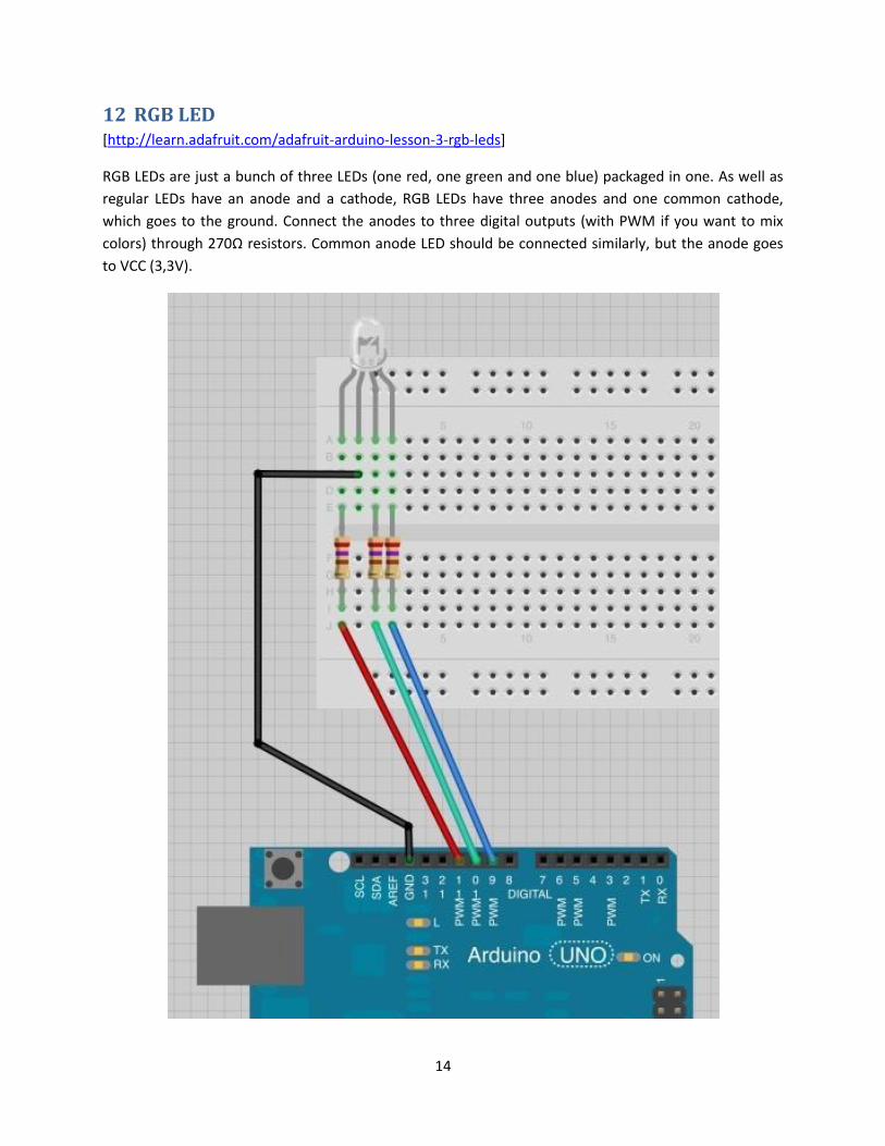
RGB LEDs are just a bunch of three LEDs (one red, one green and one blue) packaged in one. As well as
regular LEDs have an anode and a cathode, RGB LEDs have three anodes and one common cathode,
which goes to the ground. Connect the anodes to three digital outputs (with PWM if you want to mix
colors) through 270Ω resistors. Common anode LED should be connected similarly, but the anode goes
to VCC (3,3V).

15

16
Here is an example code showing how to cycle colors:
/* Adafruit Arduino - Lesson 3. RGB LED */ int redPin = 11; int greenPin = 10; int bluePin = 9; void setup() { pinMode(redPin, OUTPUT); pinMode(greenPin, OUTPUT); pinMode(bluePin, OUTPUT); } void loop() { setColor(255, 0, 0); // red delay(1000); setColor(0, 255, 0); // green delay(1000); setColor(0, 0, 255); // blue delay(1000); setColor(255, 255, 0); // yellow delay(1000); setColor(80, 0, 80); // purple delay(1000); setColor(0, 255, 255); // aqua delay(1000); } void setColor(int red, int green, int blue) { analogWrite(redPin, red); analogWrite(greenPin, green); analogWrite(bluePin, blue); }
The PWM value on the pin should be assigned to the opposite value (0->255 ; 255->0) for common
anode LEDs.
Ex: setColor(0,255,255); //red
17
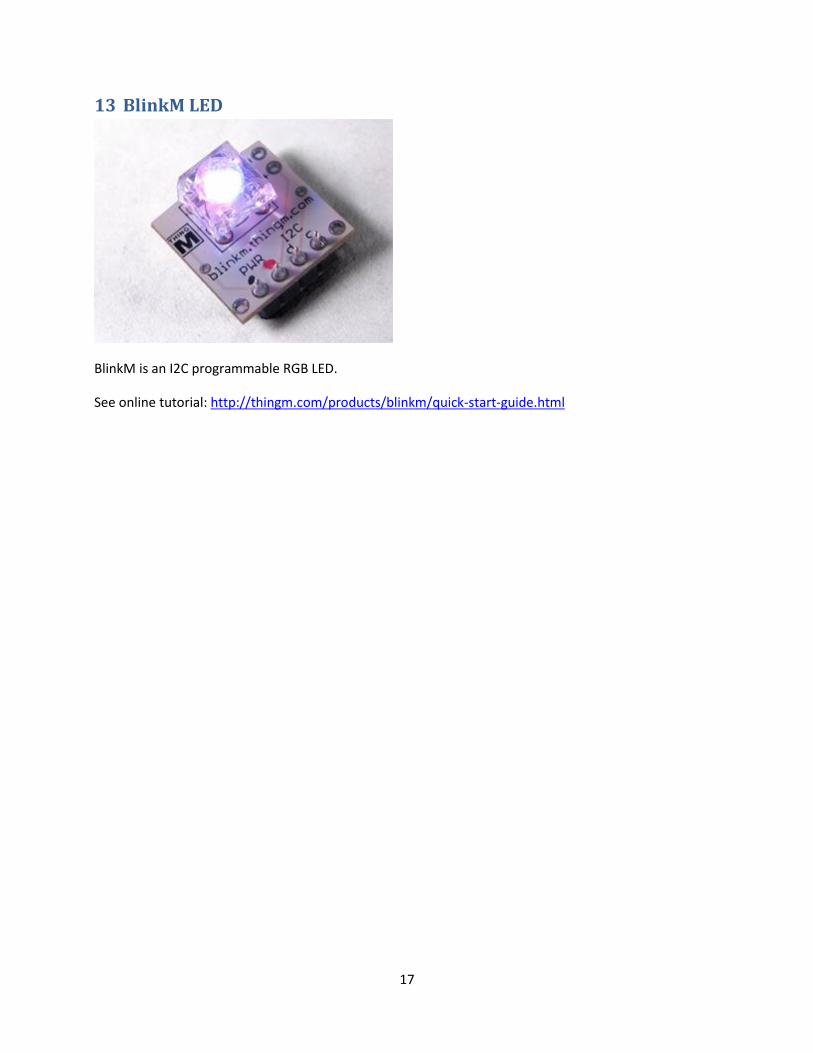
13 BlinkM LED
BlinkM is an I2C programmable RGB LED.
See online tutorial: http://thingm.com/products/blinkm/quick-start-guide.html
18
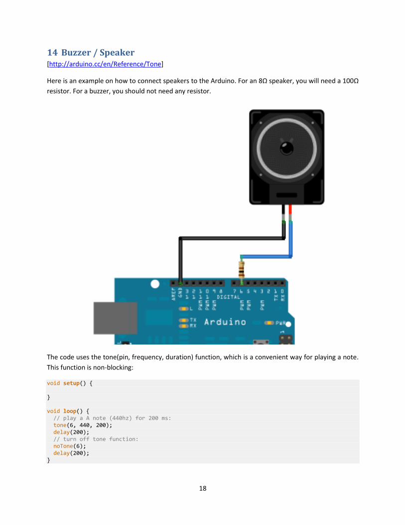
14 Buzzer / Speaker [http://arduino.cc/en/Reference/Tone]
Here is an example on how to connect speakers to the Arduino. For an 8Ω speaker, you will need a 100Ω
resistor. For a buzzer, you should not need any resistor.
The code uses the tone(pin, frequency, duration) function, which is a convenient way for playing a note.
This function is non-blocking:
void setup() { } void loop() { // play a A note (440hz) for 200 ms: tone(6, 440, 200); delay(200); // turn off tone function: noTone(6); delay(200); }

19
15 Servo motor [http://arduino.cc/en/reference/servo]
Servos have integrated gears and a shaft that can be precisely controlled. Standard servos allow the shaft
to be positioned at various angles, usually between 0 and 180 degrees. They have three wires: power,
ground, and signal. The power wire is typically red, and should be connected to the 5V pin on the
Arduino board. The ground wire is typically black or brown and should be connected to a ground pin on
the Arduino board. The signal pin is typically yellow, orange or white and should be connected to a
digital pin on the Arduino board.
The simplest way to control a servo is to use the Servo library (already included in the Arduino software).
Here is an example on how to use it:
[http://arduino.cc/en/Tutorial/Sweep]
#include <Servo.h> Servo myservo; // create servo object to control a servo // a maximum of eight servo objects can be created int pos = 0; // variable to store the servo position void setup(){ myservo.attach(9); // attaches the servo on pin 9 to the servo object } void loop(){ for(pos = 0; pos < 180; pos += 1) // goes from 0 degrees to 180 degrees { // in steps of 1 degree myservo.write(pos); // tell servo to go to position in variable 'pos' delay(15); // waits 15ms for the servo to reach the position } for(pos = 180; pos>=1; pos-=1) // goes from 180 degrees to 0 degrees { myservo.write(pos); // tell servo to go to position in variable 'pos' delay(15); // waits 15ms for the servo to reach the position } }

20
16 DC Motor and Vibrator [http://www.instructables.com/id/Simple-2-way-motor-control-for-the-arduino/]
This example shows how to having a 2-ways control of a DC Motor with an Arduino.
Since this is not the most secure way to control motors, please make sure yours are compatible with
Arduino boards before using this circuit.
Two PWM’s are used to define the speed of the motor in both directions. If you do not need a 2-ways
control (for a vibrator for instance), you can plug one end to the GND. Also, if you do not need to control
the speed, you don’t need a PWM output. To recapitulate:
Simple output and GND = one way full speed.
2 simple outputs = two ways full speed.
PWM and GND = one way speed controllable.
2 PWM’s = two ways speed controllable.
21
Here is the example code. Please note that this example uses the delay function, so it is not possible to
do anything else while the motor is running. If needed, see section 11.2 on how to avoid the delay
function.
//2-Way motor control int motorPin1 = 5; // One motor wire connected to digital pin 5 int motorPin2 = 6; // One motor wire connected to digital pin 6 // The setup() method runs once, when the sketch starts void setup() { // initialize the digital pins as an output: pinMode(motorPin1, OUTPUT); pinMode(motorPin2, OUTPUT); } // the loop() method runs over and over again, // as long as the Arduino has power void loop() { rotateLeft(150, 500); rotateRight(50, 1000); rotateRight(150, 1000); rotateRight(200, 1000); rotateLeft(255, 500); rotateRight(10, 1500); } void rotateLeft(int speedOfRotate, int length){ analogWrite(motorPin1, speedOfRotate); //rotates motor digitalWrite(motorPin2, LOW); // set the Pin motorPin2 LOW delay(length); //waits digitalWrite(motorPin1, LOW); // set the Pin motorPin1 LOW } void rotateRight(int speedOfRotate, int length){ analogWrite(motorPin2, speedOfRotate); //rotates motor digitalWrite(motorPin1, LOW); // set the Pin motorPin1 LOW delay(length); //waits digitalWrite(motorPin2, LOW); // set the Pin motorPin2 LOW }
22
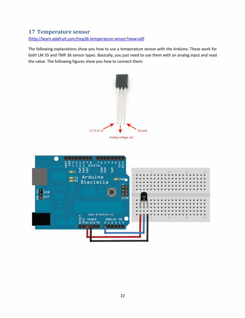
17 Temperature sensor [http://learn.adafruit.com/tmp36-temperature-sensor?view=all]
The following explanations show you how to use a temperature sensor with the Arduino. These work for
both LM 35 and TMP 36 sensor types. Basically, you just need to use them with an analog input and read
the value. The following figures show you how to connect them:
23
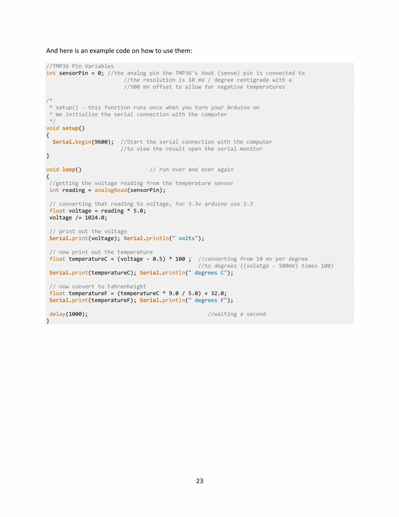
And here is an example code on how to use them:
//TMP36 Pin Variables int sensorPin = 0; //the analog pin the TMP36's Vout (sense) pin is connected to //the resolution is 10 mV / degree centigrade with a //500 mV offset to allow for negative temperatures /* * setup() - this function runs once when you turn your Arduino on * We initialize the serial connection with the computer */ void setup() { Serial.begin(9600); //Start the serial connection with the computer //to view the result open the serial monitor } void loop() // run over and over again { //getting the voltage reading from the temperature sensor int reading = analogRead(sensorPin); // converting that reading to voltage, for 3.3v arduino use 3.3 float voltage = reading * 5.0; voltage /= 1024.0; // print out the voltage Serial.print(voltage); Serial.println(" volts"); // now print out the temperature float temperatureC = (voltage - 0.5) * 100 ; //converting from 10 mv per degree //to degrees ((volatge - 500mV) times 100) Serial.print(temperatureC); Serial.println(" degrees C"); // now convert to Fahrenheight float temperatureF = (temperatureC * 9.0 / 5.0) + 32.0; Serial.print(temperatureF); Serial.println(" degrees F"); delay(1000); //waiting a second }
24
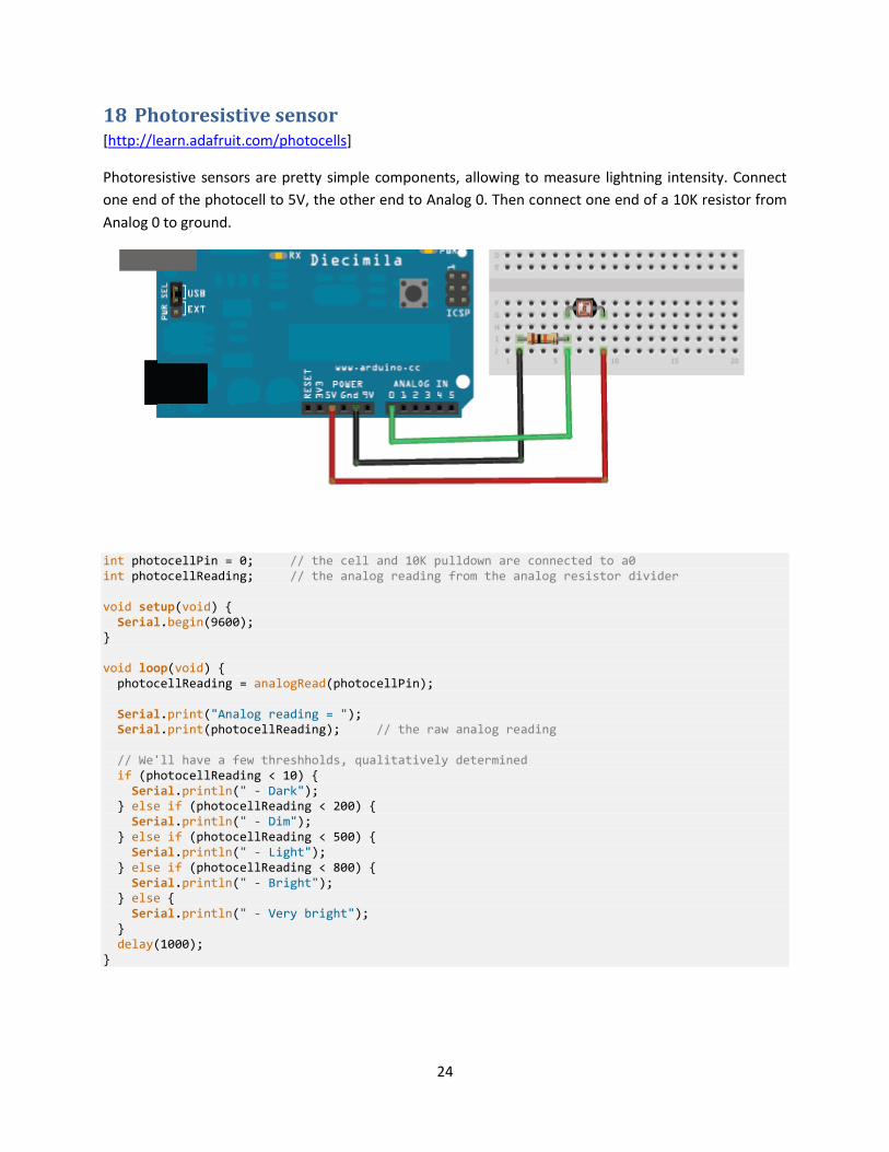
18 Photoresistive sensor [http://learn.adafruit.com/photocells]
Photoresistive sensors are pretty simple components, allowing to measure lightning intensity. Connect
one end of the photocell to 5V, the other end to Analog 0. Then connect one end of a 10K resistor from
Analog 0 to ground.
int photocellPin = 0; // the cell and 10K pulldown are connected to a0 int photocellReading; // the analog reading from the analog resistor divider void setup(void) { Serial.begin(9600); } void loop(void) { photocellReading = analogRead(photocellPin); Serial.print("Analog reading = "); Serial.print(photocellReading); // the raw analog reading // We'll have a few threshholds, qualitatively determined if (photocellReading < 10) { Serial.println(" - Dark"); } else if (photocellReading < 200) { Serial.println(" - Dim"); } else if (photocellReading < 500) { Serial.println(" - Light"); } else if (photocellReading < 800) { Serial.println(" - Bright"); } else { Serial.println(" - Very bright"); } delay(1000); }

25
19 Flex sensor [http://bildr.org/2012/11/flex-sensor-arduino/]
The flex sensor is basically a variable resistor that reacts to bends. Unbent it measures about 22KΩ, to
40KΩ when bend 180º.
int flexSensorPin = A0; //analog pin 0 void setup(){ Serial.begin(9600); } void loop(){ int flexSensorReading = analogRead(flexSensorPin); Serial.println(flexSensorReading); //In my tests I was getting a reading on the arduino between 512, and 614. //Using map(), you can convert that to a larger range like 0-100. int flex0to100 = map(flexSensorReading, 512, 614, 0, 100); Serial.println(flex0to100); delay(250); //just here to slow down the output for easier reading }

26
20 Vibration sensor [http://www.arduino.cc/en/Tutorial/Knock]
The following scheme shows a piezo element connected to the arduino, which have exactly the same
purpose as our kind of vibration sensor. Thus, you can connect them the same way:
+ connection of the piezo attached to analog in 0.
- connection of the piezo attached to ground.
1MΩ resistor attached from analog in 0 to ground.

27
/* Knock Sensor This sketch reads a piezo element to detect a knocking sound. It reads an analog pin and compares the result to a set threshold. If the result is greater than the threshold, it writes "knock" to the serial port, and toggles the LED on pin 13. */ // these constants won't change: const int ledPin = 13; // led connected to digital pin 13 const int knockSensor = A0; // the piezo is connected to analog pin 0 const int threshold = 100; // threshold value to decide when the detected sound is a knock or not // these variables will change: int sensorReading = 0; // variable to store the value read from the sensor pin int ledState = LOW; // variable used to store the last LED status, to toggle the light void setup() { pinMode(ledPin, OUTPUT); // declare the ledPin as as OUTPUT Serial.begin(9600); // use the serial port } void loop() { // read the sensor and store it in the variable sensorReading: sensorReading = analogRead(knockSensor); // if the sensor reading is greater than the threshold: if (sensorReading >= threshold) { // toggle the status of the ledPin: ledState = !ledState; // update the LED pin itself: digitalWrite(ledPin, ledState); // send the string "Knock!" back to the computer, followed by newline Serial.println("Knock!"); } delay(100); // delay to avoid overloading the serial port buffer }

28
21 Force resistive sensor [http://learn.adafruit.com/force-sensitive-resistor-fsr]
[http://www.lextronic.fr/P1793-capteur-de-force-fsr2.html]
The connection is pretty simple, since a FSR is just a variable resistor:
One pin to 5V.
The other pin to an analog input.
Pull-down 10KΩ resistor to the ground.
The following example code prints the analog value on the serial, and changes the brightness of an LED
connected on a PWM output. This is a good example of the map() function use, allowing to map the
analog input range (0-1023) to the analog output (PWM) range (0-255).
// FSR testing sketch. int fsrAnalogPin = 0; // FSR is connected to analog 0 int LEDpin = 11; // connect Red LED to pin 11 (PWM pin) int fsrReading; // the analog reading from the FSR resistor divider int LEDbrightness; void setup(void) { Serial.begin(9600); // We'll send debugging information via the Serial monitor pinMode(LEDpin, OUTPUT); } void loop(void) { fsrReading = analogRead(fsrAnalogPin); Serial.print("Analog reading = "); Serial.println(fsrReading); // we'll need to change the range from the analog reading (0-1023) down to the range // used by analogWrite (0-255) with map! LEDbrightness = map(fsrReading, 0, 1023, 0, 255); // LED gets brighter the harder you press analogWrite(LEDpin, LEDbrightness); delay(100); }
29
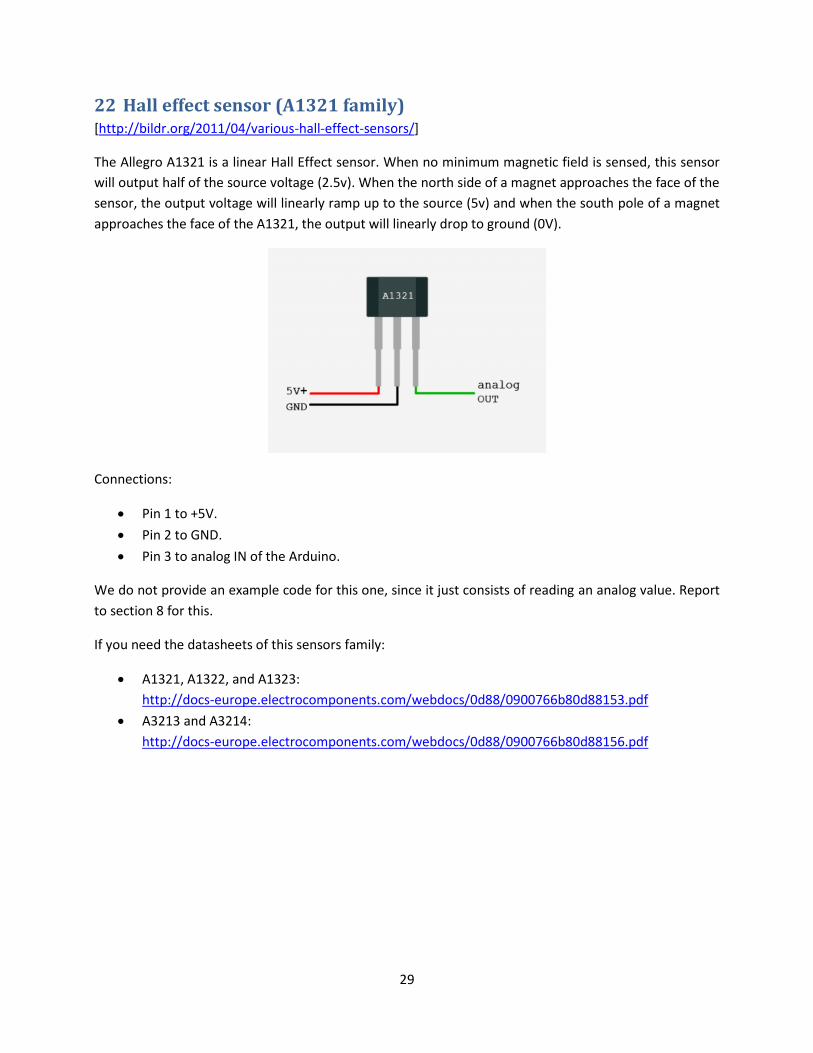
22 Hall effect sensor (A1321 family) [http://bildr.org/2011/04/various-hall-effect-sensors/]
The Allegro A1321 is a linear Hall Effect sensor. When no minimum magnetic field is sensed, this sensor
will output half of the source voltage (2.5v). When the north side of a magnet approaches the face of the
sensor, the output voltage will linearly ramp up to the source (5v) and when the south pole of a magnet
approaches the face of the A1321, the output will linearly drop to ground (0V).
Connections:
Pin 1 to +5V.
Pin 2 to GND.
Pin 3 to analog IN of the Arduino.
We do not provide an example code for this one, since it just consists of reading an analog value. Report
to section 8 for this.
If you need the datasheets of this sensors family:
A1321, A1322, and A1323:
http://docs-europe.electrocomponents.com/webdocs/0d88/0900766b80d88153.pdf
A3213 and A3214:
http://docs-europe.electrocomponents.com/webdocs/0d88/0900766b80d88156.pdf

30
23 Capacitive sensor (MPR121) [http://bildr.org/2011/05/mpr121_arduino/]
The MPR121 is an I2C device, using a 2-wire serial connection. On the Arduino, SDA is on analog pin 4
and SCL is on analog pin 5. Since I2C devices are accessed through their address, if you want to use
several of them, just connect all the SDA and SCL pins together.
We are also going to use interrupts, so the IRQ pin of the MPR121 needs to be connected to the pin 2 or
3, which are able to trigger interrupts.
31
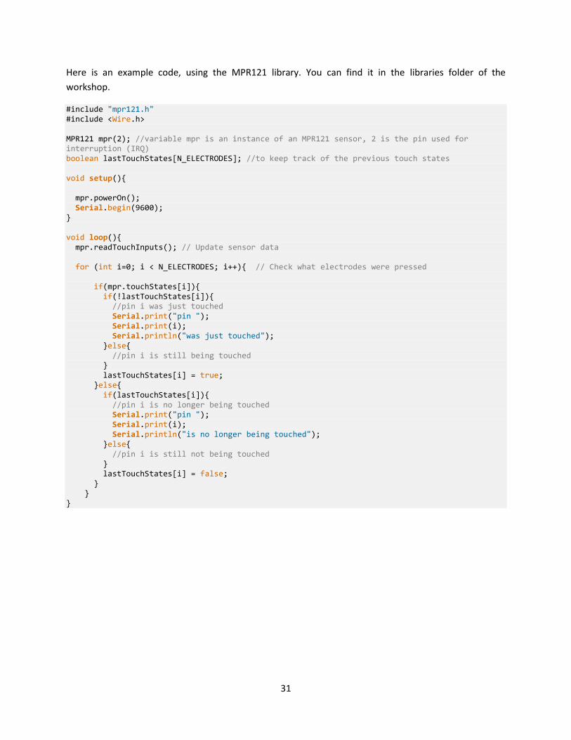
Here is an example code, using the MPR121 library. You can find it in the libraries folder of the
workshop.
#include "mpr121.h" #include <Wire.h> MPR121 mpr(2); //variable mpr is an instance of an MPR121 sensor, 2 is the pin used for interruption (IRQ) boolean lastTouchStates[N_ELECTRODES]; //to keep track of the previous touch states void setup(){ mpr.powerOn(); Serial.begin(9600); } void loop(){ mpr.readTouchInputs(); // Update sensor data for (int i=0; i < N_ELECTRODES; i++){ // Check what electrodes were pressed if(mpr.touchStates[i]){ if(!lastTouchStates[i]){ //pin i was just touched Serial.print("pin "); Serial.print(i); Serial.println("was just touched"); }else{ //pin i is still being touched } lastTouchStates[i] = true; }else{ if(lastTouchStates[i]){ //pin i is no longer being touched Serial.print("pin "); Serial.print(i); Serial.println("is no longer being touched"); }else{ //pin i is still not being touched } lastTouchStates[i] = false; } } }
32
24 Building electrodes for capacitive sensing (MPR121) Electrodes can be built easily with any conductive material. Depending on the surface of the electrode
and on the threshold settings you can detect touch events from any part of the human body or even
proximity events.
You can build electrodes by attaching aluminum strips to the MPR121 paths or by using conductive ink
paths.
Note: conductive ink need at least 15 minutes to dry. Ticker paths can require more time but have less
resistance.
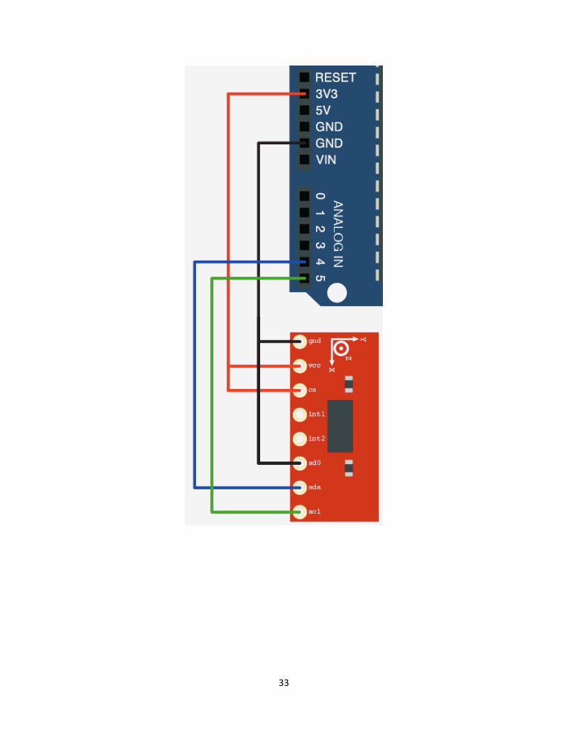
25 Accelerometer (ADXL345) [http://bildr.org/2011/03/adxl345-arduino/]
The MPR121 is an I2C device, using a 2-wire serial connection. On the Arduino, SDA is on analog pin 4
and SCL is on analog pin 5. Since I2C devices are accessed through their address, if you want to use
several of them, just connect all the SDA and SCL pins together.
33

34
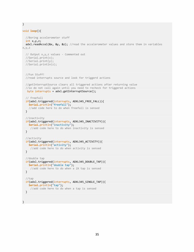
Here is an example code, using the ADXL345 library. You can find it in the libraries folder of the
workshop. The library allows to read accelerometer values with the readAccel() method, and to receive
simple gesture-like events (freefall, inactivity, activity, single-tap, double-tap). See the example code
below:
#include <Wire.h> #include <ADXL345.h> ADXL345 adxl; //variable adxl is an instance of the ADXL345 library void setup(){ Serial.begin(9600); adxl.powerOn(); //set activity/ inactivity thresholds (0-255) adxl.setActivityThreshold(75); //62.5mg per increment adxl.setInactivityThreshold(75); //62.5mg per increment adxl.setTimeInactivity(10); // how many seconds of no activity is inactive? //look of activity movement on this axes - 1 == on; 0 == off adxl.setActivityX(1); adxl.setActivityY(1); adxl.setActivityZ(1); //look of inactivity movement on this axes - 1 == on; 0 == off adxl.setInactivityX(1); adxl.setInactivityY(1); adxl.setInactivityZ(1); //look of tap movement on this axes - 1 == on; 0 == off adxl.setTapDetectionOnX(0); adxl.setTapDetectionOnY(0); adxl.setTapDetectionOnZ(1); //set values for what is a tap, and what is a double tap (0-255) adxl.setTapThreshold(50); //62.5mg per increment adxl.setTapDuration(15); //625μs per increment adxl.setDoubleTapLatency(80); //1.25ms per increment adxl.setDoubleTapWindow(200); //1.25ms per increment //set values for what is considered freefall (0-255) adxl.setFreeFallThreshold(7); //(5 - 9) recommended - 62.5mg per increment adxl.setFreeFallDuration(45); //(20 - 70) recommended - 5ms per increment //setting all interupts to take place on int pin 1 //I had issues with int pin 2, was unable to reset it adxl.setInterruptMapping( ADXL345_INT_SINGLE_TAP_BIT, ADXL345_INT1_PIN ); adxl.setInterruptMapping( ADXL345_INT_DOUBLE_TAP_BIT, ADXL345_INT1_PIN ); adxl.setInterruptMapping( ADXL345_INT_FREE_FALL_BIT, ADXL345_INT1_PIN ); adxl.setInterruptMapping( ADXL345_INT_ACTIVITY_BIT, ADXL345_INT1_PIN ); adxl.setInterruptMapping( ADXL345_INT_INACTIVITY_BIT, ADXL345_INT1_PIN ); //register interupt actions - 1 == on; 0 == off adxl.setInterrupt( ADXL345_INT_SINGLE_TAP_BIT, 1); adxl.setInterrupt( ADXL345_INT_DOUBLE_TAP_BIT, 1); adxl.setInterrupt( ADXL345_INT_FREE_FALL_BIT, 1); adxl.setInterrupt( ADXL345_INT_ACTIVITY_BIT, 1); adxl.setInterrupt( ADXL345_INT_INACTIVITY_BIT, 1);
35
} void loop(){ //Boring accelerometer stuff int x,y,z; adxl.readAccel(&x, &y, &z); //read the accelerometer values and store them in variables x,y,z // Output x,y,z values - Commented out //Serial.print(x); //Serial.print(y); //Serial.println(z); //Fun Stuff! //read interrupts source and look for triggerd actions //getInterruptSource clears all triggered actions after returning value //so do not call again until you need to recheck for triggered actions byte interrupts = adxl.getInterruptSource(); // freefall if(adxl.triggered(interrupts, ADXL345_FREE_FALL)){ Serial.println("freefall"); //add code here to do when freefall is sensed } //inactivity if(adxl.triggered(interrupts, ADXL345_INACTIVITY)){ Serial.println("inactivity"); //add code here to do when inactivity is sensed } //activity if(adxl.triggered(interrupts, ADXL345_ACTIVITY)){ Serial.println("activity"); //add code here to do when activity is sensed } //double tap if(adxl.triggered(interrupts, ADXL345_DOUBLE_TAP)){ Serial.println("double tap"); //add code here to do when a 2X tap is sensed } //tap if(adxl.triggered(interrupts, ADXL345_SINGLE_TAP)){ Serial.println("tap"); //add code here to do when a tap is sensed } }

36
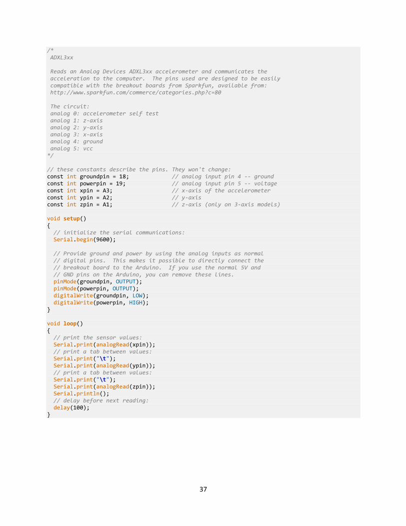
26 Accelerometer (ADXL311) [http://www.arduino.cc/en/Tutorial/ADXL3xx]
37
/* ADXL3xx Reads an Analog Devices ADXL3xx accelerometer and communicates the acceleration to the computer. The pins used are designed to be easily compatible with the breakout boards from Sparkfun, available from: http://www.sparkfun.com/commerce/categories.php?c=80 The circuit: analog 0: accelerometer self test analog 1: z-axis analog 2: y-axis analog 3: x-axis analog 4: ground analog 5: vcc */ // these constants describe the pins. They won't change: const int groundpin = 18; // analog input pin 4 -- ground const int powerpin = 19; // analog input pin 5 -- voltage const int xpin = A3; // x-axis of the accelerometer const int ypin = A2; // y-axis const int zpin = A1; // z-axis (only on 3-axis models) void setup() { // initialize the serial communications: Serial.begin(9600); // Provide ground and power by using the analog inputs as normal // digital pins. This makes it possible to directly connect the // breakout board to the Arduino. If you use the normal 5V and // GND pins on the Arduino, you can remove these lines. pinMode(groundpin, OUTPUT); pinMode(powerpin, OUTPUT); digitalWrite(groundpin, LOW); digitalWrite(powerpin, HIGH); } void loop() { // print the sensor values: Serial.print(analogRead(xpin)); // print a tab between values: Serial.print("\t"); Serial.print(analogRead(ypin)); // print a tab between values: Serial.print("\t"); Serial.print(analogRead(zpin)); Serial.println(); // delay before next reading: delay(100); }