ijesrt /archive-2016/may-2016/58_simulation...in this project it is mainly focused to ... generating...
TRANSCRIPT

[Gunanithy, 5(5): May, 2016] ISSN: 2277-9655
Impact Factor: 3.785
http: // www.ijesrt.com © International Journal of Engineering Sciences & Research Technology
[369]
IJESRT INTERNATIONAL JOURNAL OF ENGINEERING SCIENCES & RESEARCH
TECHNOLOGY
SIMULATION OF POWER GENERATION FROM SPEED BREAKERS USING
ROLLER MECHANISM Mr. Gunanithy.s *, Prof. S.Nagarajan
* M.Tech, Department Of Mechanical Engineering, Hindustan Institute of Technology and Science,
Padur,Chennai, India
Professor, Hindustan Institute of Technology and Science,Padur,Chennai, India
DOI: 10.5281/zenodo.51441
ABSTRACT Nowadays, power is the primary need for the survival of human life. Researches shows that large amount of power
is generated from non-renewable energy resources compared to that of renewable energy resources. The extensive
usage of available resources in recent years created a demand for the future generation. To overcome this problem
we need to utilize renewable energy sources for power generation and conservation. Beneath speed breaker, setting
up an electro-mechanical unit known to be power hump, could help in conserving wasted kinetic energy and use it
for power generation. This generated power can be stored, by using different electrical devices and supply this
energy to street lights, traffic lights, and nearby areas. In this project it is mainly focused to provide the detailed
survey of power generation mechanism from renewable energy resources by making an analysis on the Roller
mechanisms. By using the softwares like Solidworks 2015 for modeling of the mechanism,ANSYS for Analysis
and MATLAB Application for Convertor circuits and outputs are done. This gives a details view of the mechanism
generated more power output by using less weight and low cost material for its manufacturing in an efficient way
with more efficiency and less maintenance. After analysis of the mechanism through software, for the proposal of
implementation of the project in the society which will be very useful in the future
KEYWORDS: Power generation, Speed breaker, Roller mechanism,Boost convertor.
INTRODUCTION In today’s world, almost every equipment requires electricity for its working and the demand for the electricity is
increasing in many folds. In this project, studies available conventional methods for the generation of electricity
from the wasted energy. The number of vehicles passing over the speed breaker in roads is increasing .Due to this a
large amount of energy is wasted daily on the speed breaker through the friction between the speed breakers and the
vechicle tires during vehicle passes. There is possibility of storing this energy by making power generating system
under speedbreaker.The power thus generated is stored in a rechargeable device such as battery (conservation) for
future use (conversion). Generating electricity by speed breakers is an innovative and useful concept. It is an
attractive technology for optimal use of available sources This project aims to compare all the existing power
generation mechanism to make the best mechanisms which can give the better power with more efficiency. And
providing further information to improve the output of the other mechanism
SCOPE The usage of the energy is an indication of the development of the nation. A recent survey on the energy
consumption in India had published a pathetic report that 55,000 villages in India do not still have electricity. The
main problem is the population the demand is not equal to the supply. The 300 million people in india is using
power but the power produced is not always less than the power used. Many generating stations were idle due to the
fuel and political problem and other crisis. India as 46 lakhs kilometer road in it.And it is second largest road
network in the world. In these road we normally have speed breakers as already said we can store the energy that
produced in the battery and we can use the power for street lights, signals

[Gunanithy, 5(5): May, 2016] ISSN: 2277-9655
Impact Factor: 3.785
http: // www.ijesrt.com © International Journal of Engineering Sciences & Research Technology
[370]
RELATED WORK
Many research works are done on the speed breaker .Some of the works as follow Pankaj D.Jagtap et al.
investigated experimentally on the three methods of power generation from the kinetic energy of the moving
vehicle. Mohammad Ramadan et al. (2015) analysed a Speed Bump Power Generator (SBPG) system that produces
electrical power by utilizing the movements of commuting vehicles on highways, boulevards, and streets. Ghuge
N.N et al. (2014) proposed a system in that ,when the vehicle come on the speed breaker, electricity produced by
motor which acts as a generator. Aravind Reddy.B et al. (2015) designed a Free wheel and recoil spring in the rack
and pinion mechanism. Piyush Bhagdikar et al. (2014) proposed Roller mechanism. Rollers are fixed on a wooden
ramp on which vehicle passes. Ravivarma.B.K et al. proposed the energy generation methods using air piston
mechanism. The renewable source of energy from vehicle bumpers can be utilized. Antonin Stribrsky et al.
experimentally states that linear motor was fitted in the suspension system for power generation. During the sprung
and unspring of the shock absorber linear motor was actuated thus it convert vehicle vibration caused by road
disturbances in to electrical energy. Rajat Gupta et al. (2013) proposed the Hydraulic press mechanism was used to
transmit force from one point to another with the help of an incompressible working fluid and further the work will
transmitted by the crank and lever mechanism (beam engine).
COMPONENTS AND MATERIAL Roller
The Roller is made up off Aluminum 7075 T6.This material is highly Strength material only used for High stressed
structures. And it has high stress- corrosion Cracking Resistance. Though the Aluminum was light weighted it will
give high efficiency.
Spur Gear
Spur gears are mainly used for increasing the speed and for reducing the speed of the system. Here we are using
Four Spur gear with two spur gear having 76 Teeth and other two having 18 teeth. Material used in the spur gear is
AISI 1018 Mild/Low Carbon Steel
Bearing
Bearing is the part which allow relative motion between two parts. The two types of motion that bearing allows are
Rotatory and linear. Here we are using rotatory type bearing which is used in world wide which as relatively high in
friction. The type of bearing rotatory so we are using ball bearing. The material used in the ball bearing is Stainless
steel. Totally we are using 12 ball bearings, six in the Roller mechanism setup and Six in the Gear box setup.
Timing Belt And Pulley
Timing Belt drives give a positive power transmission than the other drives like chain, gears and belt. The Timing
pulley with diameter of 40MM are made up of Aluminium and the bigger one is made up of steel. The belt material
Fibre glass tensile cord with Neoprene body and nylon tooth
EXPERIMENTAL SETUP Block Diagram
Figure 1. Block Diagram

[Gunanithy, 5(5): May, 2016] ISSN: 2277-9655
Impact Factor: 3.785
http: // www.ijesrt.com © International Journal of Engineering Sciences & Research Technology
[371]
Roller Mechanism
The experimental setup of the roller mechanism contains the following items which are already mentioned in the
materials and component section. The setup of the project as follows ,the basement of the setup consist of two set of
wooden ramp which tends to hold the roller mechanism. One set of roller mechanism contain three ball bearing on
each ramp with distance of 111.5mm gap. The ball bearing is made of chrome steel to avoid rust. And three Rollers
R1,R2,R3 is attached to the ball bearing in both ends. Surface of the roller is attached plain rubber to increase the
friction between the the roller and the vehicles tyre.The rollers are connected with Timing belt to avoid loss .One
end of the roller R1 and Roller R2 have one timing pulley each T3,T4 and Roller R2 have another timing pulley in
other end T5 .At the same side roller R3 have timing pulley T6.T3 and T4 is connected with Timing Belt and Other
timing Pulley T5 is connected to T6 pulley .This connection will give same speed in all the Roller.In R1 another
pulley T1 is placed which is 156mm diameter is connected to T2 of 40mm placed in the gear box setup
Gear Box
The experimental setup of gear box contain box setup which has two set of ramp. In one set of ramp three Ball
bearing is connected with distance of 94mm and three shafts S1,S2,S3 are connected with the ball bearing as shown
in the figure.First shaft S1 consist of one spur gear G1 with 76 teeth which is meshed with second spur gear G2 with
18 teeth which is placed in the parallel shaft S2.In the same shaft S2 another Spur gear G3 with 76 teeth is placed.
The Gear G3 is meshed with spur gear G4 with 18 teeth is placed in the shaft S3 parallel to S2.The shaft S3 is the
output shaft R3 it is directly connected with generater shaft.The shaft S1 as timing pulley T2 in one end of the shaft.
Figure 2. Roller Mechanism with gear box The simulation of the this model is done in the ansys is shown below in the figure.It is taken as the weight or mass
of the vehicle as 250 kg with driver passing over the roller. At the same time one of the Roller carries a weight of
100 kg for a given instant and there will be some rotation on the roller, so we shall take on safer side that the roller
rotated at 100 rad/s .

[Gunanithy, 5(5): May, 2016] ISSN: 2277-9655
Impact Factor: 3.785
http: // www.ijesrt.com © International Journal of Engineering Sciences & Research Technology
[372]
Figure 3. Roller Mechanism which applying load Below figure shows the results of the simulation on the Roller. The maximum stress on the bearings is 0.62MPa
which is within limit of the Stainless steel yield point.
Figure 4. Roller Mechanism After analysis
Working
When a vehicle is passing over the roller it tends the roller R1 to move due to friction between the tire and the roller
surface. The Rollers R2 and R3 is connected with the R1 so these two rollers also will Rotate. And all three rollers
are connected with each other roller will rotate if any of the roller rotates. So the end of the Roller R1 it is connected
to Gearbox with help of Timing unequal pulley. The speed of the roller output is increased by means gearbox .The
output of the Gear box is connected to 18 phase generator.
Table 1. Output Speed of the Gear box Shaft Connected To the generator Shaft
S.no Speed of the Roller R1(rpm) Input Speed of the Generator Shaft(rpm)
1 5 350
2 11 760
3 15 1030
4 20 1375

[Gunanithy, 5(5): May, 2016] ISSN: 2277-9655
Impact Factor: 3.785
http: // www.ijesrt.com © International Journal of Engineering Sciences & Research Technology
[373]
PERMANENT MAGNET SYNCRONOUS GENERATOR Generally in permanent magnet synchronous generator there will not be any external coil is there to excite the field.
But the inbuilt permanent magnets will provide the excitation required by the generator. The word synchronous tells
that the both the rotor and the stator are synchronous to each other that both are rotating at the same speed. This
synchronous generators are used more and often in many industries or in many commercial methods to produce the
power. The synchronous generator is connected to the turbines like gas, steam, water and converts their mechanical
power into the electrical power.
NEW FRANKLIN THOMPSON’S 18 PHASE GENERATOR The permanent magnet motor are developed day by day in technology and recently the franklin Thompson company
as invented a new 18 phase split rotor permanent magnet synchronous generator that have the capacity of about 30
KW generation that also in a low RPM. This proposed PMSG is a modified model of a normal PMSG. Its coil
arrangements have been modified in order to get a output of the above mentioned range. This hand wired generator
gives an efficient of about 92.3%.
In this PMSG there is only one rotor and a stator which is modified into a 18 phase generator that has a better
efficiency than the previous version of 9 phase generator. This generator can be modified to get a efficiency of 97%.
Figure 5. 18 Phase Generator
This generator gives the AC output but it already has a inbuilt rectifier hence the output ac is converted into the dc
and given out as dc power.
RECTIFIER CIRCUIT The Output Voltage generated is given to the rectifier which is given to the in-bulit rectifier which is shows in the
Simulink modeling shown below.
Figure 6. Full wave rectifier Circuit

[Gunanithy, 5(5): May, 2016] ISSN: 2277-9655
Impact Factor: 3.785
http: // www.ijesrt.com © International Journal of Engineering Sciences & Research Technology
[374]
Simulation
The Simulation of Rectifier is done in Mat lab Software the output are obtained from the Mat lab software .
Figure 7 Simulation of Full wave rectifier Circuit in MATLAB
This rectifier converts the AC power into DC power and it gives the DC output.The below shown table are tested
result.
Table 2. Output of Rectifier Circuit
Load Speed(rpm) Input Current(A)Output Voltage (A)Output
20 350 4 79
20 760 8 160
20 1375 12 239
BOOST CONVERTER In order to increase the output DC voltage of the rectifier we need DC-DC boost converter which boosts the given
voltage into gain of four which is the gain of the boost convertor designed for this project.
Figure 8. Boost Convertor Circuit

[Gunanithy, 5(5): May, 2016] ISSN: 2277-9655
Impact Factor: 3.785
http: // www.ijesrt.com © International Journal of Engineering Sciences & Research Technology
[375]
Simulation
Now the three different output voltages from rectifier is given to the boost convertor and the simulation results were
given below. The Simulation of Boost convertor is done in Mat lab Software the output are obtained from the Mat
lab software .
Figure 9. Stimulation of Boost Convertor Circuit in MATLAB
Table 3. Specifiation of Boost Convertor
S.no Component Input Speed of the Generator Shaft(rpm)
1 Input Voltage 79,160,260
2 Ouput Voltage 300,500,900
3 Inductor 470uF,1000V
4 Capacitor 35mH,50Amps
5 MOSFET IXFB 60N80P
6 Driver circuit TLP 250
7 Control Circuit Pic Kit 3 Micro Controller
8 Diode NTE 6047
The pulses generated for the Boost Convertor is shown Below
Figure 10.Switch pulse –Current vs Time

[Gunanithy, 5(5): May, 2016] ISSN: 2277-9655
Impact Factor: 3.785
http: // www.ijesrt.com © International Journal of Engineering Sciences & Research Technology
[376]
The output voltage for 79 volt input voltage
Figure 11.Voltage vs Time
The output Current for 79 volt input voltage
Figure 12.Current vs Time

[Gunanithy, 5(5): May, 2016] ISSN: 2277-9655
Impact Factor: 3.785
http: // www.ijesrt.com © International Journal of Engineering Sciences & Research Technology
[377]
The output voltage for 160 volt input voltage
Figure 13.Voltage vs Time
The output Current for 160 volt input voltage
Figure 14.Voltage vs Time

[Gunanithy, 5(5): May, 2016] ISSN: 2277-9655
Impact Factor: 3.785
http: // www.ijesrt.com © International Journal of Engineering Sciences & Research Technology
[378]
The output voltage for 239 volt input voltage
Figure 15.Voltage vs Time
The output Current for 239 volt input voltage
Figure 16.Voltage vs Time
[Gunanithy, 5(5): May, 2016] ISSN: 2277-9655
Impact Factor: 3.785
http: // www.ijesrt.com © International Journal of Engineering Sciences & Research Technology
[379]
Table 4. Output of the Boost Convertor
S.no Load(Ohms) Input
Voltage(V)
Output
Current(A)
Output Voltage(V) Power
Output(W)
1 20 79 15 300 4500
2 20 160 20 500 10000
3 20 239 45 900 40500
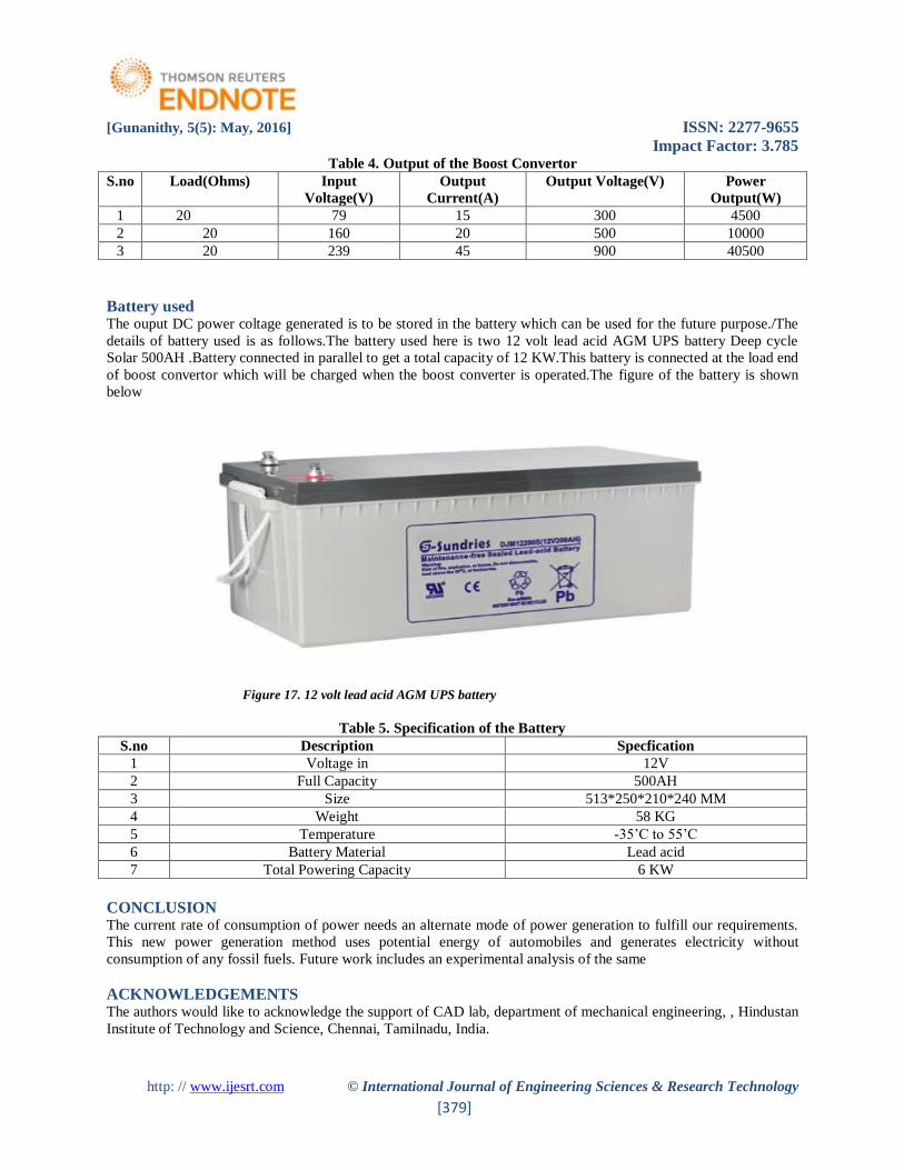
Battery used The ouput DC power coltage generated is to be stored in the battery which can be used for the future purpose./The
details of battery used is as follows.The battery used here is two 12 volt lead acid AGM UPS battery Deep cycle
Solar 500AH .Battery connected in parallel to get a total capacity of 12 KW.This battery is connected at the load end
of boost convertor which will be charged when the boost converter is operated.The figure of the battery is shown
below
Figure 17. 12 volt lead acid AGM UPS battery
Table 5. Specification of the Battery
S.no Description Specfication
1 Voltage in 12V
2 Full Capacity 500AH
3 Size 513*250*210*240 MM
4 Weight 58 KG
5 Temperature -35’C to 55’C
6 Battery Material Lead acid
7 Total Powering Capacity 6 KW
CONCLUSION The current rate of consumption of power needs an alternate mode of power generation to fulfill our requirements.
This new power generation method uses potential energy of automobiles and generates electricity without
consumption of any fossil fuels. Future work includes an experimental analysis of the same
ACKNOWLEDGEMENTS The authors would like to acknowledge the support of CAD lab, department of mechanical engineering, , Hindustan
Institute of Technology and Science, Chennai, Tamilnadu, India.

[Gunanithy, 5(5): May, 2016] ISSN: 2277-9655
Impact Factor: 3.785
http: // www.ijesrt.com © International Journal of Engineering Sciences & Research Technology
[380]
REFERENCES [1] Pankaj D.Jagtap, Sanket D.Pardeshi, Angad G.Khade and Varun Sathe, “A Review: Comparison of
different mechanism for electricitygeneration using speed breaker”, Multidisciplinary journal of
research in engineering and technology, Vol. 1 No. 2, pp. 202-206,2014. ISSN 2348-6953
[2]“Using speed bump for power generation –Experimental study“ by Mohamad Ramadan, Mahmoud Khaled
& Hicham El Hage, “Energy procedia 2015
[3]“Every Speed Breaker Is A Source Of Power “by N. N. Ghuge, Arati Sathe, Varsha Patil, Anagha
Warankar , “Int. Journal of Engineering Research and Applications “Vol. 4, Issue 3( Version 6), March
2014 ISSN : 2248-9622, Vol. 4, Issue 3( Version 6), March 2014, pp.01-05
[4]“ Modified Design Of Speed Breaker For Power Generation “by B. Aravind Reddy1, T.Venkata Sahaj2,
Yarram Arun Kumar3, D.Ramana Reddy4 “ International Journal of Research in Engineering and
Technology ” Volume: 04 Special Issue: 02 | NCIRET-2015 eISSN: 2319-1163 | pISSN: 2321-7308
[5]“ GENERATION OF ELECTRICITY WITH THE USE OF SPEED BREAKERS “by Piyush Bhagdikar,
Shubham Gupta, Navneet Rana, R. Jegadeeshwaran “ International Journal of Advances in Engineering &
Technology”, May, 2014 ISSN: 22311963
[6] B. Santhosh Sarma, V. Jyothi, D. Sudhir, “Design of Power Generation Unit Using Roller Mechanism”,
IOSR Journal of electrical andelectronics Engineering (IOSR-JEEE) Vol. 9 No. 3, pp 55-60, 2014. ISSN:
2278- 1676.
[7]“ Hydraulic Speed Breaker Power Generator “by Rajat Gupta, Rahul Gupta , “Int. Journal of Engineering
Research and Applications” ISSN : 2248-9622, Vol. 3, Issue 6, Nov-Dec 2013, pp.502-506
[8]K.Ravivarma, B.Divya, C.P.Prajith, A.Sivamurugan and K.Vengatesan, “Power generation using hydraulic
mechanism at speedbumper”, International Journal of Scientific and Engineering Research, vol. 4 No. 6,
2013. ISSN 2229-5518.
[9]Antonin Stribrsky, Katerina Hyniova, Jaroslav Honcu and Ales Kruczek, “Energy Recuperation in
Automotive Active Suspension withLinear Electric Motor”, Proceedings of the 15th Mediterranean
Conference on Control& Automation,July 27-29, 2007, Athens – Greece.
[10] http://www.ftcinnovations.com/
[11]http://www.gates.com/products/industrial/industrial-belts/synchronous-belts/powergrip-timing-
belts