architecture and engineering division project …
TRANSCRIPT
ISSUED DATE REFERENCE PERSON REVISION #
1/23/2015 Administrator REVISION DATE APPROVED BY PAGE
ARCHITECTURE AND ENGINEERING DIVISION
PROJECT MANAGER’S MANUAL AND
BUILDING DESIGN AND CONSTRUCTION
STANDARDS
by
Architecture & Engineering Division
Department of General Services
City of Tucson
General Services Department
Architecture & Engineering Division
ISSUED DATE REFERENCE PERSON REVISION #
1/23/2015 Administrator REVISION DATE APPROVED BY PAGE
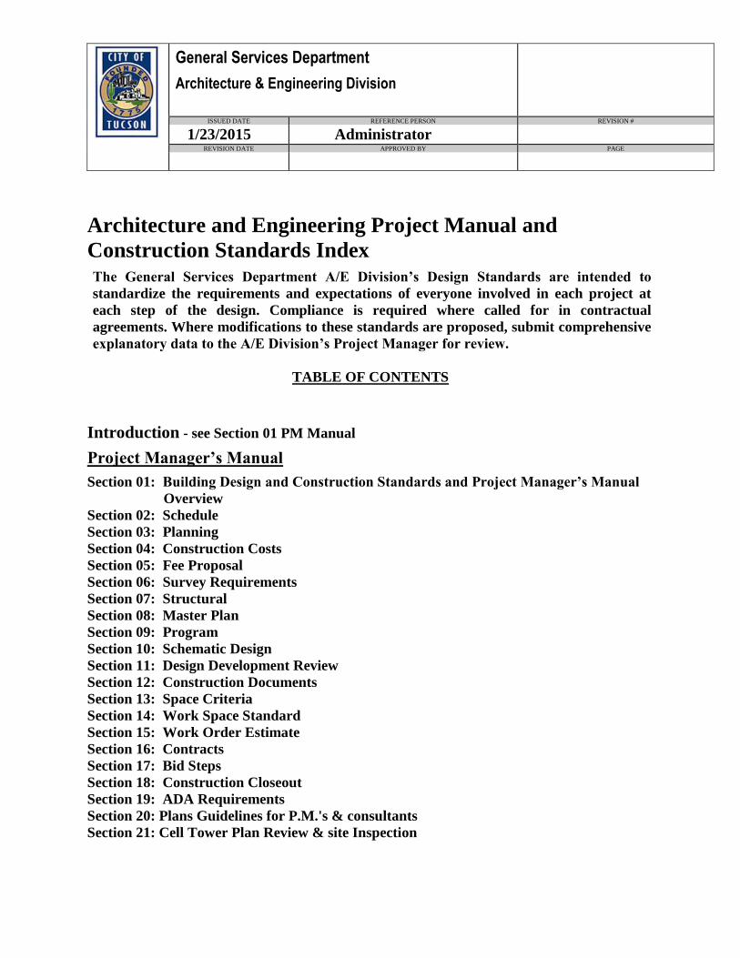
Architecture and Engineering Project Manual and
Construction Standards Index The General Services Department A/E Division’s Design Standards are intended to
standardize the requirements and expectations of everyone involved in each project at
each step of the design. Compliance is required where called for in contractual
agreements. Where modifications to these standards are proposed, submit comprehensive
explanatory data to the A/E Division’s Project Manager for review.
TABLE OF CONTENTS
Introduction - see Section 01 PM Manual
Project Manager’s Manual
Section 01: Building Design and Construction Standards and Project Manager’s Manual
Overview
Section 02: Schedule
Section 03: Planning
Section 04: Construction Costs
Section 05: Fee Proposal
Section 06: Survey Requirements
Section 07: Structural
Section 08: Master Plan
Section 09: Program
Section 10: Schematic Design
Section 11: Design Development Review
Section 12: Construction Documents
Section 13: Space Criteria
Section 14: Work Space Standard
Section 15: Work Order Estimate
Section 16: Contracts
Section 17: Bid Steps
Section 18: Construction Closeout
Section 19: ADA Requirements
Section 20: Plans Guidelines for P.M.'s & consultants
Section 21: Cell Tower Plan Review & site Inspection
General Services Department
Architecture & Engineering Division
ISSUED DATE REFERENCE PERSON REVISION #
1/23/2015 Administrator REVISION DATE APPROVED BY PAGE
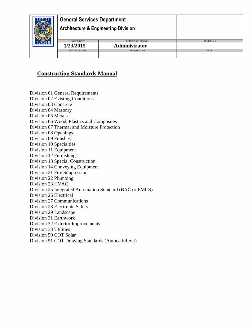
Construction Standards Manual
Division 01 General Requirements
Division 02 Existing Conditions
Division 03 Concrete
Division 04 Masonry
Division 05 Metals
Division 06 Wood, Plastics and Composites
Division 07 Thermal and Moisture Protection
Division 08 Openings
Division 09 Finishes
Division 10 Specialties
Division 11 Equipment
Division 12 Furnishings
Division 13 Special Construction
Division 14 Conveying Equipment
Division 21 Fire Suppression
Division 22 Plumbing
Division 23 HVAC
Division 25 Integrated Automation Standard (BAC or EMCS)
Division 26 Electrical
Division 27 Communications
Division 28 Electronic Safety
Division 29 Landscape
Division 31 Earthwork
Division 32 Exterior Improvements
Division 33 Utilities
Division 50 COT Solar
Division 51 COT Drawing Standards (Autocad/Revit)
General Services Department
Architecture &Engineering Division
Architecture and Engineering Division Standards
Building Design and Construction Standards and Project Manager’s Manual Overview
ISSUED DATE REFERENCE PERSON Revision # REVISION DATE
1/28/2015 A&E Administrator
Revised Pages PAGE
Page 1 of 1
Index Page 1 of 1 1/28/2015
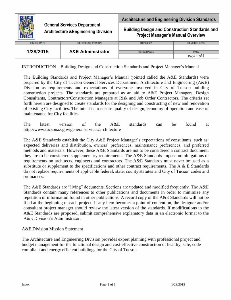
INTRODUCTION – Building Design and Construction Standards and Project Manager’s Manual
The Building Standards and Project Manager’s Manual (jointed called the A&E Standards) were
prepared by the City of Tucson General Services Department, Architecture and Engineering (A&E)
Division as requirements and expectations of everyone involved in City of Tucson building
construction projects. The standards are prepared as an aid to A&E Project Managers, Design
Consultants, Contractors/Construction Managers at Risk and Job Order Contractors. The criteria set
forth herein are designed to create standards for the designing and constructing of new and renovation
of existing City facilities. The intent is to ensure quality of design, economy of operation and ease of
maintenance for City facilities.
The latest version of the A&E standards can be found at
http://www.tucsonaz.gov/generalservices/architecture
The A&E Standards establish the City A&E Project Manager’s expectations of consultants, such as:
expected deliveries and distribution, owners’ preferences, maintenance preferences, and preferred
methods and materials. However, these A&E Standards are not to be considered a contract document,
they are to be considered supplementary requirements. The A&E Standards impose no obligations or
requirements on architects, engineers and contractors. The A&E Standards must never be used as a
substitute or supplement to the specifications and other contract requirements. The A & E Standards
do not replace requirements of applicable federal, state, county statutes and City of Tucson codes and
ordinances.
The A&E Standards are “living” documents. Sections are updated and modified frequently. The A&E
Standards contain many references to other publications and documents in order to minimize any
repetition of information found in other publications. A record copy of the A&E Standards will not be
filed at the beginning of each project. If any item becomes a point of contention, the designer and/or
consultant project manager should review the latest version of the standards. If modifications to the
A&E Standards are proposed, submit comprehensive explanatory data in an electronic format to the
A&E Division’s Administrator.
A&E Division Mission Statement
The Architecture and Engineering Division provides expert planning with professional project and
budget management for the functional design and cost-effective construction of healthy, safe, code
compliant and energy efficient buildings for the City of Tucson.
General Services Department
Architecture & Engineering Division
Project Manager’s Manual
SCHEMATIC DESIGN PHASE
ISSUED DATE REFERENCE PERSON REVISION # REVISION DATE
9/1/2007 A&E Administrator ADA Update 11/29/2013
Revised Pages PAGE
2 & 3 ADA Related only Page 3 of 7
Schematic Design Rev 11-29-13 MD.doc Page 3 of 7 12/5/2013
City facilities, as public buildings, shall be designed, constructed, and altered for
accessibility and use by the disabled. In this connection, with the ADA, the Department
of Justice 2010 ADA Standards for Accessible Design (ADAAG) for Title II entities shall
determine the criteria to be used for the design of these facilities to ensure accessibility
and compliance.
A PDF Format copy can be downloaded from the DOJ site at:
http://www.ada.gov/regs2010/2010ADAStandards/2010ADAStandards_prt.pdf
The specific design criteria applicable to provisions for the disabled shall be incorporated
in the Architectural Design Program document for the facility.
The DOJ standards stipulate minimums and maximums as guidelines. The City of
Tucson uses these guidelines as the minimum or maximum allowable standards within
which we prefer to provide the most comfortable design to provide universal access.
DSD shall be consulted early, and as the project proceeds, to specifically review ADA
issues/requirements.
6. Exterior wall elevations with major materials identified
7. Typical building sections with major material, building and structural systems identified
8. Architectural Floor plans, all levels
Partition layout of all spaces.
Accurate toilet room, elevator and stair layouts. Furniture and movable equipment
layouts, for ALL spaces.
9. Room finish concept for all major spaces
10. Plumbing Systems Plan
a. Fixture locations.
b. Equipment locations.
c. Narrative describing systems
City of Tucson Architecture and Engineering AutoCAD Standards and Guidelines ▀▀▀▀▀▀▀▀▀▀▀▀▀▀▀▀▀▀▀▀▀▀▀▀▀▀▀▀▀▀▀▀▀▀▀▀▀▀▀▀▀▀▀▀▀▀▀▀▀▀▀▀▀▀▀▀▀▀▀▀▀▀▀▀▀▀▀▀▀▀▀▀▀▀ September 2, 2008 page -3
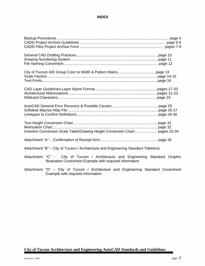
INDEX Backup Procedures ............................................................................................................ page 4 CADD Project Archive Guidelines ................................................................................... page 5-6 CADD Files Project Archive Form ................................................................................. pages 7-9 General CAD Drafting Practices................................................................................page 10 Drawing Numbering System......................................................................................page 11 File Naming Convention.............................................................................................page 12 City of Tucson A/E Group Color to Width & Pattern Matrix.....................................page 13 Scale Factors ...........................................................................................................page 14-15 Text-Fonts.................................................................................................................page 16 CAD Layer Guidelines-Layer Name Format.............................................................pages 17-20 Architectural Abbreviations ......................................................................................pages 21-23 Wildcard Characters.................................................................................................page 24 AutoCAD General Error Recovery & Possible Causes .............................................page 25 Softdesk Macros Help File ........................................................................................page 26-27 Linetypes to Confirm Definitions............................................................................... page 28-30 Text Height Conversion Chart ................................................................................. page 31 Metrication Chart...................................................................................................... page 32 Insertion Conversion Scale Table/Drawing Height Conversion Chart...................... pages 33-34 Attachment “A” - Confirmation of Receipt form……………………………………….. page 35 Attachment “B” – City of Tucson / Architecture and Engineering Standard Titleblock Attachment “C” - City of Tucson / Architecture and Engineering Standard Graphic Illustration Coversheet Example with required information Attachment “D” – City of Tucson / Architecture and Engineering Standard Coversheet Example with required information

City of Tucson Architecture and Engineering AutoCAD Standards and Guidelines ▀▀▀▀▀▀▀▀▀▀▀▀▀▀▀▀▀▀▀▀▀▀▀▀▀▀▀▀▀▀▀▀▀▀▀▀▀▀▀▀▀▀▀▀▀▀▀▀▀▀▀▀▀▀▀▀▀▀▀▀▀▀▀▀▀▀▀▀▀▀▀▀▀▀ September 2, 2008 page -4
BACKUP PROCEDURES This method assures daily, weekly and monthly backups. If a computer were to crash on Thursday, the data could be easily recovered by restoring one of the Total backups from Monday and the modified backups from Tuesday and Wednesday. BACKUP SCHEDULE
Week
Monday
Tuesday
Wednesday
Thursday
Friday
Week 1
TAPE 1
Modified Backup
TAPE 1
Modified Backup
TAPE 1
Modified Backup
TAPE 1
Modified Backup
TAPE 1 Total Backup
Week 2
TAPE 2
Modified Backup
TAPE 2
Modified Backup
TAPE 2
Modified Backup
TAPE 2
Modified Backup
TAPE 2 Total Backup
Week 3
TAPE 3
Modified Backup
TAPE 3
Modified Backup
TAPE 3
Modified Backup
TAPE 3
Modified Backup
TAPE 3 Total Backup
Week 4
TAPE 4
Modified Backup
TAPE 4
Modified Backup
TAPE 4
Modified Backup
TAPE 4
Modified Backup
TAPE 4 Total Backup
Tapes are clearly labeled BACKUP with the type of backup and day of the week indicated. For example: Modified-1_Monday. Friday tapes must be stored off-site until they are reused 4 weeks later. Note: Tapes are optional, C.D.’s are approved means of backup as well. This backup method is simply identified to help and/or assist your office with backup procedures if you don’t have one in place already. It is always a good idea to keep backup records of drawings “on-site” and an additional set “off-site”. (When submitting “As-built Electronic ACAD files” to the City of Tucson – Architecture and Engineering Division, you must submit in C.D. format, USB Flashdrive or SD Memory Card that has enough capacity and is capable of holding all of the project files. See page five, under “ELECTRONIC DRAWINGS SUBMITTAL”.)
City of Tucson Architecture and Engineering AutoCAD Standards and Guidelines ▀▀▀▀▀▀▀▀▀▀▀▀▀▀▀▀▀▀▀▀▀▀▀▀▀▀▀▀▀▀▀▀▀▀▀▀▀▀▀▀▀▀▀▀▀▀▀▀▀▀▀▀▀▀▀▀▀▀▀▀▀▀▀▀▀▀▀▀▀▀▀▀▀▀ September 2, 2008 page -5
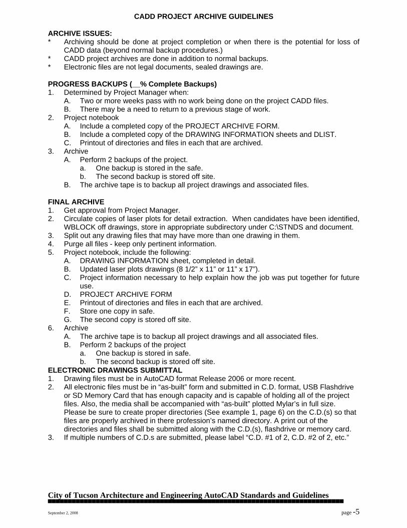
CADD PROJECT ARCHIVE GUIDELINES ARCHIVE ISSUES: * Archiving should be done at project completion or when there is the potential for loss of
CADD data (beyond normal backup procedures.) * CADD project archives are done in addition to normal backups. * Electronic files are not legal documents, sealed drawings are. PROGRESS BACKUPS (__% Complete Backups) 1. Determined by Project Manager when:
A. Two or more weeks pass with no work being done on the project CADD files. B. There may be a need to return to a previous stage of work.
2. Project notebook A. Include a completed copy of the PROJECT ARCHIVE FORM. B. Include a completed copy of the DRAWING INFORMATION sheets and DLIST. C. Printout of directories and files in each that are archived.
3. Archive A. Perform 2 backups of the project.
a. One backup is stored in the safe. b. The second backup is stored off site.
B. The archive tape is to backup all project drawings and associated files. FINAL ARCHIVE 1. Get approval from Project Manager. 2. Circulate copies of laser plots for detail extraction. When candidates have been identified,
WBLOCK off drawings, store in appropriate subdirectory under C:\STNDS and document. 3. Split out any drawing files that may have more than one drawing in them. 4. Purge all files - keep only pertinent information. 5. Project notebook, include the following:
A. DRAWING INFORMATION sheet, completed in detail. B. Updated laser plots drawings (8 1/2” x 11” or 11” x 17”). C. Project information necessary to help explain how the job was put together for future
use. D. PROJECT ARCHIVE FORM
E. Printout of directories and files in each that are archived. F. Store one copy in safe.
G. The second copy is stored off site. 6. Archive
A. The archive tape is to backup all project drawings and all associated files. B. Perform 2 backups of the project
a. One backup is stored in safe. b. The second backup is stored off site.
ELECTRONIC DRAWINGS SUBMITTAL 1. Drawing files must be in AutoCAD format Release 2006 or more recent. 2. All electronic files must be in “as-built” form and submitted in C.D. format, USB Flashdrive
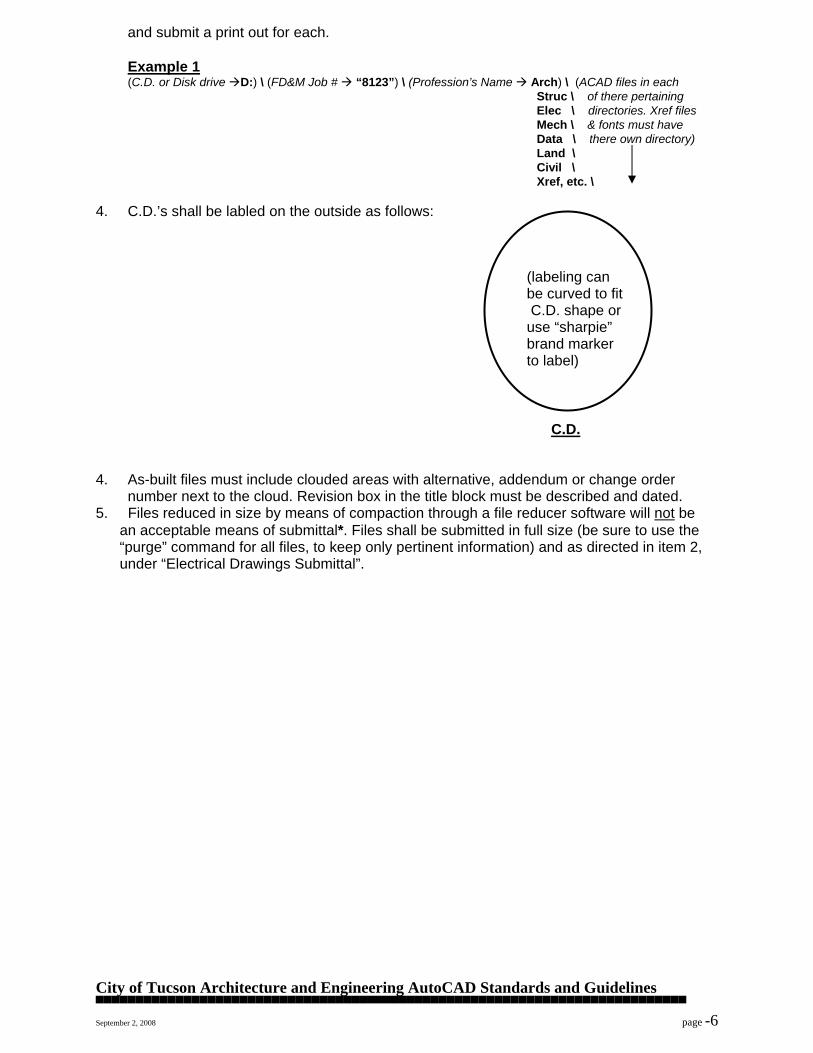
or SD Memory Card that has enough capacity and is capable of holding all of the project files. Also, the media shall be accompanied with “as-built” plotted Mylar’s in full size. Please be sure to create proper directories (See example 1, page 6) on the C.D.(s) so that files are properly archived in there profession’s named directory. A print out of the directories and files shall be submitted along with the C.D.(s), flashdrive or memory card.
3. If multiple numbers of C.D.s are submitted, please label “C.D. #1 of 2, C.D. #2 of 2, etc.”
City of Tucson Architecture and Engineering AutoCAD Standards and Guidelines ▀▀▀▀▀▀▀▀▀▀▀▀▀▀▀▀▀▀▀▀▀▀▀▀▀▀▀▀▀▀▀▀▀▀▀▀▀▀▀▀▀▀▀▀▀▀▀▀▀▀▀▀▀▀▀▀▀▀▀▀▀▀▀▀▀▀▀▀▀▀▀▀▀▀ September 2, 2008 page -6
and submit a print out for each. Example 1
(C.D. or Disk drive D:) \ (FD&M Job # “8123”) \ (Profession’s Name Arch) \ (ACAD files in each Struc \ of there pertaining Elec \ directories. Xref files Mech \ & fonts must have Data \ there own directory) Land \ Civil \ Xref, etc. \
4. C.D.’s shall be labled on the outside as follows: (labeling can be curved to fit C.D. shape or use “sharpie” brand marker to label) C.D. 4. As-built files must include clouded areas with alternative, addendum or change order number next to the cloud. Revision box in the title block must be described and dated. 5. Files reduced in size by means of compaction through a file reducer software will not be
an acceptable means of submittal*. Files shall be submitted in full size (be sure to use the “purge” command for all files, to keep only pertinent information) and as directed in item 2, under “Electrical Drawings Submittal”.
City of Tucson Architecture and Engineering AutoCAD Standards and Guidelines ▀▀▀▀▀▀▀▀▀▀▀▀▀▀▀▀▀▀▀▀▀▀▀▀▀▀▀▀▀▀▀▀▀▀▀▀▀▀▀▀▀▀▀▀▀▀▀▀▀▀▀▀▀▀▀▀▀▀▀▀▀▀▀▀▀▀▀▀▀▀▀▀▀▀ September 2, 2008 page -7
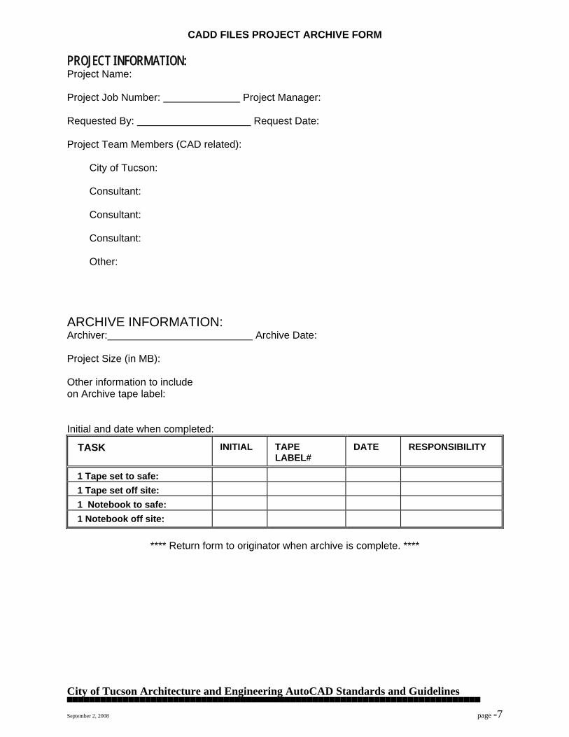
CADD FILES PROJECT ARCHIVE FORM PROJECT INFORMATION: Project Name: Project Job Number: Project Manager: Requested By: Request Date: Project Team Members (CAD related):
City of Tucson:
Consultant:
Consultant:
Consultant:
Other: ARCHIVE INFORMATION: Archiver: Archive Date: Project Size (in MB): Other information to include on Archive tape label: Initial and date when completed:
TASK
INITIAL
TAPE LABEL#
DATE
RESPONSIBILITY
1 Tape set to safe:
1 Tape set off site:
1 Notebook to safe:
1 Notebook off site:
**** Return form to originator when archive is complete. ****
City of Tucson Architecture and Engineering AutoCAD Standards and Guidelines ▀▀▀▀▀▀▀▀▀▀▀▀▀▀▀▀▀▀▀▀▀▀▀▀▀▀▀▀▀▀▀▀▀▀▀▀▀▀▀▀▀▀▀▀▀▀▀▀▀▀▀▀▀▀▀▀▀▀▀▀▀▀▀▀▀▀▀▀▀▀▀▀▀▀ September 2, 2008 page -8
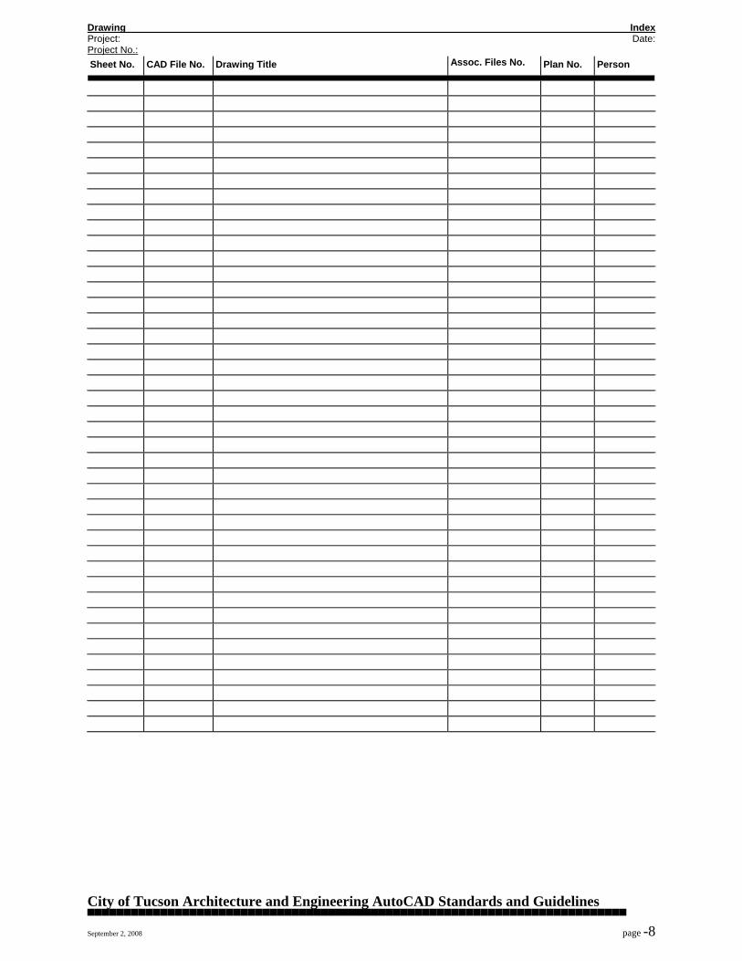
Drawing Index Project: Date: Project No.: Sheet No.
CAD File No.
Drawing Title Assoc. Files No.
Plan No.
Person
City of Tucson Architecture and Engineering AutoCAD Standards and Guidelines ▀▀▀▀▀▀▀▀▀▀▀▀▀▀▀▀▀▀▀▀▀▀▀▀▀▀▀▀▀▀▀▀▀▀▀▀▀▀▀▀▀▀▀▀▀▀▀▀▀▀▀▀▀▀▀▀▀▀▀▀▀▀▀▀▀▀▀▀▀▀▀▀▀▀ September 2, 2008 page -9
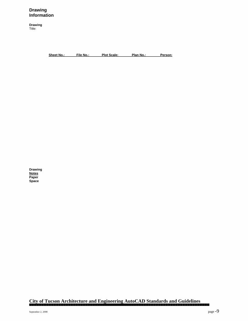
Drawing Information Drawing Title:
Sheet No.: File No.: Plot Scale: Plan No.: Person:
Drawing Notes Paper Space

City of Tucson Architecture and Engineering AutoCAD Standards and Guidelines ▀▀▀▀▀▀▀▀▀▀▀▀▀▀▀▀▀▀▀▀▀▀▀▀▀▀▀▀▀▀▀▀▀▀▀▀▀▀▀▀▀▀▀▀▀▀▀▀▀▀▀▀▀▀▀▀▀▀▀▀▀▀▀▀▀▀▀▀▀▀▀▀▀▀ September 2, 2008 page -10
GENERAL CAD DRAFTING PRACTICES 1. SAVING: Save frequently, AutoCAD's autosave feature must be set to save every 15 minutes or
less. Use the SAVETIME command. 2. DRAWING ORIGIN: The lower left hand corner of all title blocks should orginate from the global 0,0
point. 3. LIMITS: Drawing limits match plotting sheet size. 4. COLOR & LINETYPE: Element color and linetype are set bylayer, not by entity. Do NOT change
entity color or linetype with the CHANGE PROPERTY command, use layers to these parameters. 5. SNAPS & OBJECTS: Snaps and objects are to be used for all precision placement. 6. LTSCALE: LTSCALE should equal DIMSCALE. 7. REGENAUTO: REGENAUTO is turned off and the EXPERT variable is set to 0. 8. HIGHLIGHT: HIGHLIGHT is always set to 1 (on). 9. EXITING A DRAWING: Always save drawings with the full drawing visible (Zoom All). 10. BLOCKS:
A. All blocks are always created on layer 0. B. Blocks that are used in drawings of various scales are to be created at full scale, 1"=1". C. Do not explode BLOCKS or hatch patterns.
11. XREFS: A. All xrefs shall be binded to the drawing file used in the final archival submittal(s). 12. TEXT:
A. Only standard AutoCAD and Softdesk architectural fonts are to be used. “Chisel.shx” font style is to be used or approved equivalent.
B. Text heights are not set with the STYLE command. C. CHISEL font is used for all notes and titles. D. All plotted notes are 1/8" high, upper case. E. All plotted titles are 1/4" high, upper case F. Arrow size shall be the same as the text height and solid terminator. Architects must use Tick
Marks when dimensioning; these shall be 1/8” long and 1/64” thick when dimensioned in paper space, and they shall be slanted 45 degrees to the dimension line.
13. PAPER SPACE VS. MODEL SPACE: A. Title blocks, general notes, sheet notes, and entities that are not attached to entities that
represent “ real objects”, must be placed in Paper Space. The rest will be placed in Model Space.
14. TITLE BLOCK: A. C.O.T. title block will be used as an insertable drawing with title block. It contains an editable
text block with the insertion point at the lower right hand corner of the outline border; it may be edited with the DDATTE command. Title Blocks files must be inserted in Layer 0 in Paper Space in 0,0 coordinate; they are drawn at 1” = 1”.
B. At title of drawing, the bubble size must be 11/16” in diameter, text inside the bubble and title must be 1/4” high, text of the drawing scale must be 1/8” high.
C. At section and details cuts, the bubble size must be 9/16” in diameter, text inside bubble must be 1/8”.
D. The current City of Tucson / Architecture and Engineering titleblock shall be required for all projects small or large. See Attachment “B”. Contact Octavio A. SantaMaria, Jr. at (520) 791-5111 x331 or [email protected] to obtain ACAD files.
E. The coversheet for every project will not need a titleblock. The coversheet shall require the information (at a minimum) provided on the coversheet example. See Attachment “D”. Note:
The coversheet does not need to look exactly like the example, but all information shown on the example is required. Projects that are new stand alone facilities, major renovations or expansions will require an additional coversheet in front of the above mentioned sheet containing some type of graphical illustration and the title of the project. See Attachment “C”. If you have any questions, please contact Octavio A. SantaMaria, Jr. at (520) 791-5111 x331 or [email protected] .

City of Tucson Architecture and Engineering AutoCAD Standards and Guidelines ▀▀▀▀▀▀▀▀▀▀▀▀▀▀▀▀▀▀▀▀▀▀▀▀▀▀▀▀▀▀▀▀▀▀▀▀▀▀▀▀▀▀▀▀▀▀▀▀▀▀▀▀▀▀▀▀▀▀▀▀▀▀▀▀▀▀▀▀▀▀▀▀▀▀ September 2, 2008 page -11
DRAWING NUMBERING SYSTEM
A. Facilities Design and Management has adopted the standard system offered by The Architect’s Handbook of Professional Practice as outlined by the American Institute of Architects. The type of system used is for “Average to Large Projects”. ( See Attachment “A”). For your convenience we have reproduced the architectural section below.
ARCHITECTURAL DRAWINGS A0.1,2,3... Index, Symbols, Abbreviations, Notes, Location Map A1.1,2,3... Demolition, Site Plan, Temporary Work A2.1,2,3... Plans, Room Material Schedule, Door Schedule, Key Drawings A3.1,2,3... Sections, Exterior Elevations A4.1,2,3... Detailed Floor Plans A5.1,2,3... Interior Elevations A6.1,2,3... Reflected Ceiling Plans A7.1,2,3... Vertical Circulation, Stairs, Elevators, Escalators A8.1,2,3... Exterior Details A9.1,2,3... Interior Details B. These nine sections will always remain the same no matter how large or small the project may be. Additional drawings may be added with groups without interrupting the alphanumerical order. For small projects, unused sections will not be noted and will be skipped; always maintaining the 0 to 9 numbering system. EXAMPLE 1.- If a large project has 4 floors plans that need to be divided into West and East sections, a sample of the drawings to be used may be numbered as followed: A4.1.1 for Detailed Floor Plan of the first floor West/East section A4.3.2 for Detailed Floor Plan of the third floor East/West section EXAMPLE 2.- If a large project has 9 floors of reflected ceiling floor plans and the architect wishes to divide each floor into restrooms, lobby, offices and conference rooms, and the conference rooms are to be divided into small and large, a sample of the drawings to be used may be numbered as followed: A6.3.2.1 for Reflected Ceiling Plans of the third floor, conference room small/large A6.4.2.2 for Reflected Ceiling Plans of the fourth floor, conference room large/small EXAMPLE 3.- If a small project has only one sheet with a location map and notes, one floor plan, two exterior elevations and one stair detail, the full index of drawings may be as follows: A0 Index, Location Map and Notes A2 Floor Plan A3.1 North Elevation A3.2 South Elevation A7 Stair Details EXAMPLE 4.- If a project is only comprised of the demolition of a two story office building, the full index of drawings may be as follows: A0 Index, Location Map and Temporary Work A1.1 Site Plan and General Notes A1.2.1 Demolition Phasing Plan-Stage 1 A1.2.2 Demolition Phasing Plan-Stage 2 A1.2.3 Demolition Phasing Plan-Stage 3
City of Tucson Architecture and Engineering AutoCAD Standards and Guidelines ▀▀▀▀▀▀▀▀▀▀▀▀▀▀▀▀▀▀▀▀▀▀▀▀▀▀▀▀▀▀▀▀▀▀▀▀▀▀▀▀▀▀▀▀▀▀▀▀▀▀▀▀▀▀▀▀▀▀▀▀▀▀▀▀▀▀▀▀▀▀▀▀▀▀ September 2, 2008 page -12
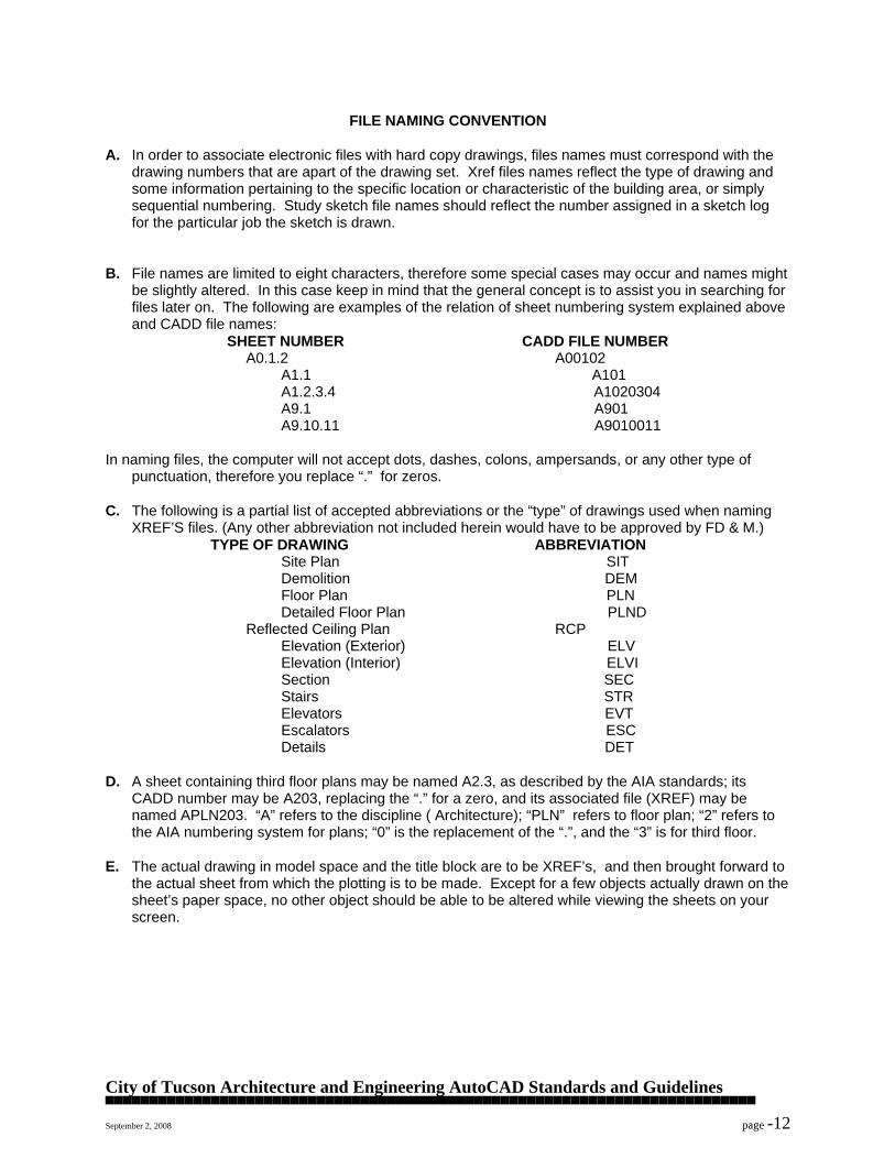
FILE NAMING CONVENTION
A. In order to associate electronic files with hard copy drawings, files names must correspond with the drawing numbers that are apart of the drawing set. Xref files names reflect the type of drawing and some information pertaining to the specific location or characteristic of the building area, or simply sequential numbering. Study sketch file names should reflect the number assigned in a sketch log for the particular job the sketch is drawn.
B. File names are limited to eight characters, therefore some special cases may occur and names might
be slightly altered. In this case keep in mind that the general concept is to assist you in searching for files later on. The following are examples of the relation of sheet numbering system explained above and CADD file names:
SHEET NUMBER CADD FILE NUMBER A0.1.2 A00102 A1.1 A101 A1.2.3.4 A1020304 A9.1 A901 A9.10.11 A9010011 In naming files, the computer will not accept dots, dashes, colons, ampersands, or any other type of
punctuation, therefore you replace “.” for zeros. C. The following is a partial list of accepted abbreviations or the “type” of drawings used when naming
XREF’S files. (Any other abbreviation not included herein would have to be approved by FD & M.) TYPE OF DRAWING ABBREVIATION Site Plan SIT Demolition DEM Floor Plan PLN Detailed Floor Plan PLND Reflected Ceiling Plan RCP Elevation (Exterior) ELV Elevation (Interior) ELVI Section SEC Stairs STR Elevators EVT Escalators ESC Details DET D. A sheet containing third floor plans may be named A2.3, as described by the AIA standards; its
CADD number may be A203, replacing the “.” for a zero, and its associated file (XREF) may be named APLN203. “A” refers to the discipline ( Architecture); “PLN” refers to floor plan; “2” refers to the AIA numbering system for plans; “0” is the replacement of the “.”, and the “3” is for third floor.
E. The actual drawing in model space and the title block are to be XREF’s, and then brought forward to
the actual sheet from which the plotting is to be made. Except for a few objects actually drawn on the sheet’s paper space, no other object should be able to be altered while viewing the sheets on your screen.
General Services Department
Architecture & Engineering Division
Project Manager’s Manual
SCHEMATIC DESIGN PHASE
ISSUED DATE REFERENCE PERSON REVISION # REVISION DATE
9/1/2007 A&E Administrator ADA Update 11/29/2013
Revised Pages PAGE
2 & 3 ADA Related only Page 4 of 7
Schematic Design Rev 11-29-13 MD.doc Page 4 of 7 12/5/2013
11. Fire Protection System Narrative
a. Provide system description.
b. Provide system description of all special use Fire Protection Systems (Mission
critical computer rooms, e.g.)
12. Mechanical System Plan & Narrative
a. Equipment locations and types.
b. Supply, return, and exhaust duct one-line diagram.
c. Controls concept. (narrative)
d. Establish life cycle analysis of energy consuming equipment and options
(conceptual).
e. HVAC load and sizing calculations shall be provided indicating the size of the
major mechanical system components (narrative).
13. Power Distribution
Power distribution equipment locations. (Utility source, service entrance gear,
distribution and lighting panels, “first pass” amperages and voltages of each. At SD’s,
square foot basis is acceptable.)
14. Lighting
a. Lighting fixture concept and layout shown for the majority of interior and exterior
lit areas.
b. Special requirements noted.
c. Life cycle cost analysis, for the purpose of analyzing lighting system options
(conceptual).
15. Roofing
Roofing systems with a minimum slope of ½” per foot (slopes less than ½”per foot is not
permitted per City standard):
Provide a roof as described in the standards that has a Full System Guarantee with no
dollar limit including all roof penetrations. Guarantee shall include the roof system from
the deck up. Damage repair as part of the guarantee shall include replacement of wet
insulation and damaged decking.
Roofing systems for slopes greater than 3” per foot shall rely on the manufacture’s best
warranties
City of Tucson Architecture and Engineering AutoCAD Standards and Guidelines ▀▀▀▀▀▀▀▀▀▀▀▀▀▀▀▀▀▀▀▀▀▀▀▀▀▀▀▀▀▀▀▀▀▀▀▀▀▀▀▀▀▀▀▀▀▀▀▀▀▀▀▀▀▀▀▀▀▀▀▀▀▀▀▀▀▀▀▀▀▀▀▀▀▀ September 2, 2008 page -13
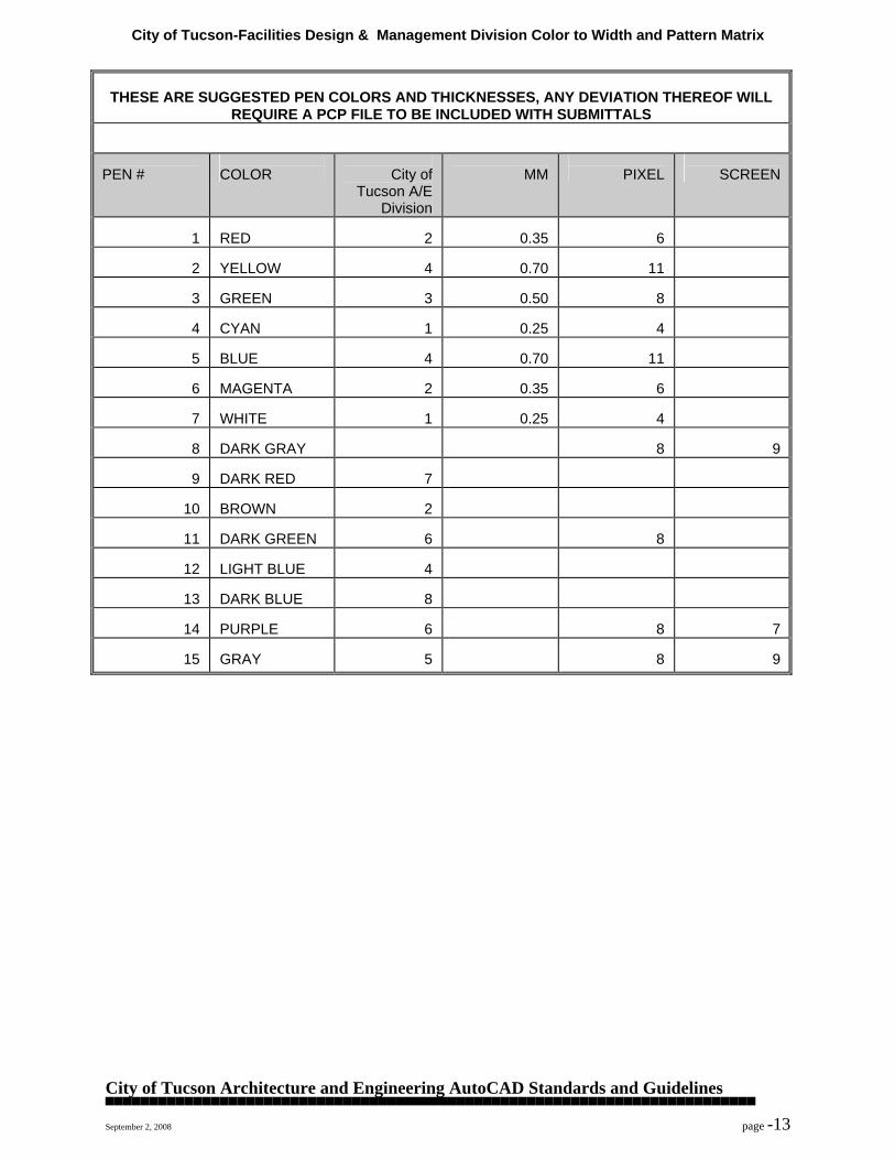
City of Tucson-Facilities Design & Management Division Color to Width and Pattern Matrix THESE ARE SUGGESTED PEN COLORS AND THICKNESSES, ANY DEVIATION THEREOF WILL
REQUIRE A PCP FILE TO BE INCLUDED WITH SUBMITTALS
PEN #
COLOR
City of
Tucson A/E Division
MM
PIXEL
SCREEN
1
RED
2
0.35
6
2
YELLOW
4
0.70
11
3
GREEN
3
0.50
8
4
CYAN
1
0.25
4
5
BLUE
4
0.70
11
6
MAGENTA
2
0.35
6
7
WHITE
1
0.25
4
8
DARK GRAY
8
9
9
DARK RED
7
10
BROWN
2
11
DARK GREEN
6
8
12
LIGHT BLUE
4
13
DARK BLUE
8
14
PURPLE
6
8
7
15
GRAY
5
8
9
City of Tucson Architecture and Engineering AutoCAD Standards and Guidelines ▀▀▀▀▀▀▀▀▀▀▀▀▀▀▀▀▀▀▀▀▀▀▀▀▀▀▀▀▀▀▀▀▀▀▀▀▀▀▀▀▀▀▀▀▀▀▀▀▀▀▀▀▀▀▀▀▀▀▀▀▀▀▀▀▀▀▀▀▀▀▀▀▀▀ September 2, 2008 page -14
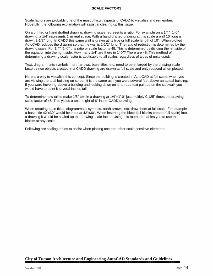
SCALE FACTORS Scale factors are probably one of the most difficult aspects of CADD to visualize and remember. Hopefully, the following explanation will assist in clearing up this issue. On a printed or hand drafted drawing, drawing scale represents a ratio. For example on a 1/4"=1'-0" drawing, a 1/4" represents 1' in real space. With a hand drafted drawing at this scale a wall 10' long is drawn 2-1/2" long. In CADD this same wall is drawn at its true or full scale length of 10'. When plotted AutoCAD reduces the drawing so that the wall is 2-1/2" long. The ratio of reduction is determined by the drawing scale. For 1/4"=1'-0" this ratio or scale factor is 48. This is determined by dividing the left side of the equation into the right side. How many 1/4" are there in 1'-0"? There are 48. This method of determining a drawing scale factor is applicable to all scales regardless of types of units used. Text, diagrammatic symbols, north arrows, base titles, etc. need to be enlarged by the drawing scale factor, since objects created in a CADD drawing are drawn at full scale and only reduced when plotted. Here is a way to visualize this concept. Since the building is created in AutoCAD at full scale, when you are viewing the total building on screen it is the same as if you were several feet above an actual building. If you were hovering above a building and looking down on it, to read text painted on the sidewalk you would have to paint it several inches tall. To determine how tall to make 1/8" text in a drawing at 1/4"=1'-0" just multiply 0.125" times the drawing scale factor of 48. This yields a text height of 6" in the CADD drawing. When creating base titles, diagrammatic symbols, north arrows, etc. draw them at full scale. For example a base title 42"x30" would be input at 42"x30". When inserting the block (all blocks created full scale) into a drawing it would be scaled up the drawing scale factor. Using this method enables you to use the blocks at any scale. Following are scaling tables to assist when placing text and other scale sensitive elements.
City of Tucson Architecture and Engineering AutoCAD Standards and Guidelines ▀▀▀▀▀▀▀▀▀▀▀▀▀▀▀▀▀▀▀▀▀▀▀▀▀▀▀▀▀▀▀▀▀▀▀▀▀▀▀▀▀▀▀▀▀▀▀▀▀▀▀▀▀▀▀▀▀▀▀▀▀▀▀▀▀▀▀▀▀▀▀▀▀▀ September 2, 2008 page -15
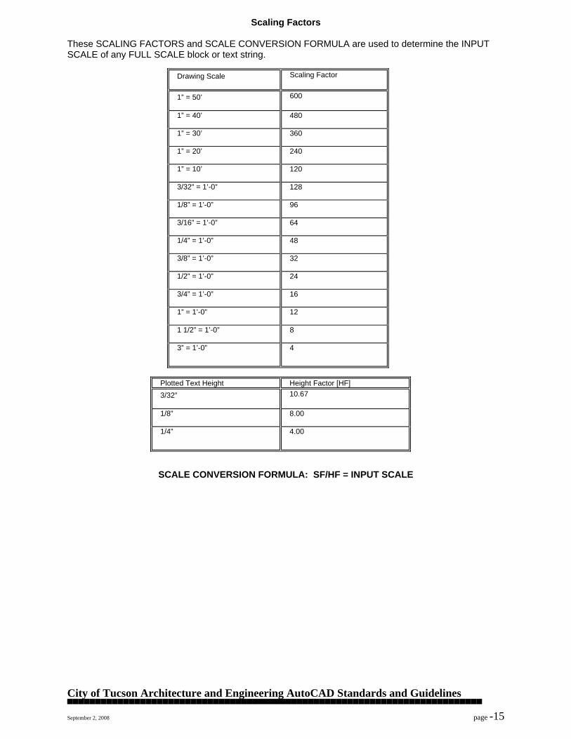
Scaling Factors These SCALING FACTORS and SCALE CONVERSION FORMULA are used to determine the INPUT SCALE of any FULL SCALE block or text string.
Drawing Scale
Scaling Factor
1” = 50’
600
1” = 40’
480
1” = 30’
360
1” = 20’
240
1” = 10’
120
3/32” = 1’-0”
128
1/8” = 1’-0”
96
3/16” = 1’-0”
64
1/4” = 1’-0”
48
3/8” = 1’-0”
32
1/2” = 1’-0”
24
3/4” = 1’-0”
16
1” = 1’-0” 12
1 1/2” = 1’-0” 8
3” = 1’-0” 4
Plotted Text Height Height Factor [HF] 3/32”
10.67
1/8” 8.00
1/4” 4.00
SCALE CONVERSION FORMULA: SF/HF = INPUT SCALE
City of Tucson Architecture and Engineering AutoCAD Standards and Guidelines ▀▀▀▀▀▀▀▀▀▀▀▀▀▀▀▀▀▀▀▀▀▀▀▀▀▀▀▀▀▀▀▀▀▀▀▀▀▀▀▀▀▀▀▀▀▀▀▀▀▀▀▀▀▀▀▀▀▀▀▀▀▀▀▀▀▀▀▀▀▀▀▀▀▀ September 2, 2008 page -16
TEXT - Fonts 1. Styles - City of Tucson-Architecture and Engineering Division uses the standard AutoCAD fonts
and the fonts which come with Auto-Architect. When using them please take note of the following:
A. There is a frequent misunderstanding with AutoCAD as to the difference between a text style
and a text font. The style is the user given name of a text style. The text font is the font file name that is designated for the user named text style. All styles at City of Tucson-Architecture and Engineering Division are named after their corresponding font file.
Example: COMMAND: STYLE Text style name (or ?) <CHISEL>: Font file <CHISEL>: Height <0'-0">: Width factor <1.0>: Obliquing angle <0.00>: Backwards? <N> Upside-down? <N> Vertical? <N> CHISEL is now the current text style.
B. Typical creation parameters for user created styles.
a. It is advisable that you do not fix the height of a text style with the style command. This allows for variations of heigth with the same style and font while reducing the number of styles used. If you do fix the height that text style is fixed and can not be adjusted for future use or modification.
Example: Text style <CHISEL> Font file <CHISEL> Height: <0'-0"> Width factor: <1.0> Obliquing angle: <0.00> Backwards: <No> Upside-down: <No> Vertical: <No>
City of Tucson Architecture and Engineering AutoCAD Standards and Guidelines ▀▀▀▀▀▀▀▀▀▀▀▀▀▀▀▀▀▀▀▀▀▀▀▀▀▀▀▀▀▀▀▀▀▀▀▀▀▀▀▀▀▀▀▀▀▀▀▀▀▀▀▀▀▀▀▀▀▀▀▀▀▀▀▀▀▀▀▀▀▀▀▀▀▀ September 2, 2008 page -17
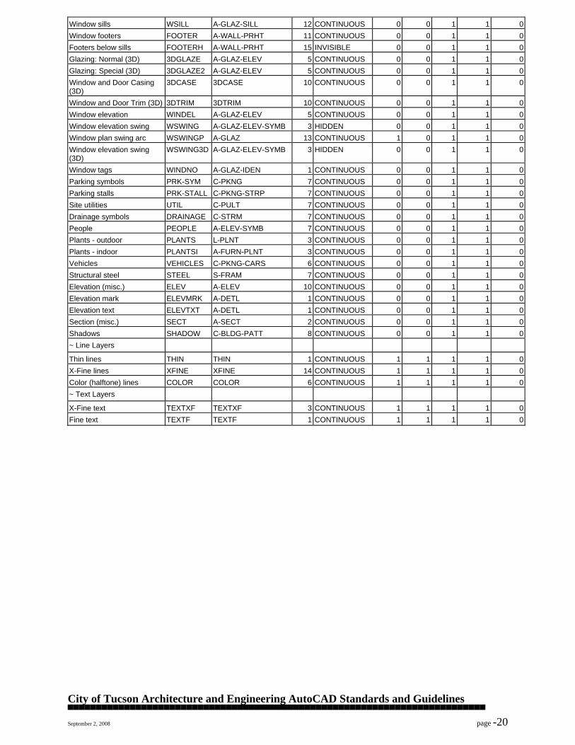
CAD Layer Guidelines - Layer Name Format The City of Tucson utilizes the AIA standard layering guidelines as described below:
Long Format
Major Group- 1 Character. This categorization breaks the list into manageable sections, using the divisions of architectural, structural, mechanical, plumbing, fire protection, electrical, and civil engineering/site work.
Minor Group- 4 Characters. Generally Minor Groups designate assemblies or
Modifier- 4 Characters (Optional). This is an optional field for further differentiation of drawing element such as distinguishing full height walls from partial height walls or emergency lighting from general lighting.
User Defined- 1-8- Characters (Optional). This optional field may be
used to accommodate special project requirements. Examples A-Wall Walls A-Door-Iden Door Numbers Short Format
Major Group- 1 character. Minor Group- 2 character.
Modifier- 2 characters (Optional). User Defined- 1-2 characters (Optional).
Examples AWA Walls ADOID Door Numbers Source: CAD Layer Guidelines, Copyright 1990, AIA Press
City of Tucson Architecture and Engineering AutoCAD Standards and Guidelines ▀▀▀▀▀▀▀▀▀▀▀▀▀▀▀▀▀▀▀▀▀▀▀▀▀▀▀▀▀▀▀▀▀▀▀▀▀▀▀▀▀▀▀▀▀▀▀▀▀▀▀▀▀▀▀▀▀▀▀▀▀▀▀▀▀▀▀▀▀▀▀▀▀▀ September 2, 2008 page -18
*Softdesk Layer Default File: c:/adcadd/aa/setup/lan/aa_layer.dat
*Description
Keyname Layername
Color
Linetype
Trade
Plan
Level
Modifier
Auto Create
~ Architectural
Appliances APPL
A-FLOR-APPL
9
CONTINUOUS
0
0
1
1
0
Case work CASE
A-FLOR-CASE
10
CONTINUOUS
0
0
1
1
0
Casework tags CASENO
A-CASE-IDEN
1
CONTINUOUS
0
0
1
1
0
Ceiling major features CEIL
A-CLNG
5
CONTINUOUS
0
0
1
1
0
Ceiling objects CEILOBJ
A-CLNG
10
CONTINUOUS
0
0
1
1
0
Ceiling grid CEILGRID
A-CLNG-GRID
5
CONTINUOUS
0
0
1
1
0
Columns COLUMN
S-COLS
4
CONTINUOUS
0
0
1
1
0
Construction tags CONSTNO
A-CONS-IDEN
1
CONTINUOUS
0
0
1
1
0
Demolition tags DEMONO
A-DEMO-IDEN
1
CONTINUOUS
0
0
1
1
0
Doors DOOR
A-DOOR
10
CONTINUOUS
0
0
1
1
0
3D Doors 3DDOOR
A-DOOR-ELEV
10
CONTINUOUS
0
0
1
1
0
3D Door accessories DOORAC
A-DOOR-ELEV
10
CONTINUOUS
0
0
1
1
0
Door elevation DOORE
A-DOOR-ELEV
10
CONTINUOUS
0
0
1
1
0
Door elevation swing DSWING
A-DOOR-ELEV-SYMB
10
HIDDEN
0
0
1
1
0
Door elevation swing (3D) DSWING3D
A-DOOR-ELEV-SYMB
10
HIDDEN
0
0
1
1
0
Door swing arc plan DSWINGP
A-DOOR-SWG
10
HIDDEN
1
0
1
1
0
Door jamb DJAMB
A-WALL-JAMB
8
CONTINUOUS
0
0
1
1
0
3D Door jamb 3DDJAMB
A-WALL-JAMB-ELEV
8
INVISIBLE
0
0
1
1
0
2D Door sills DSILL
A-DOOR-SILL
9
CONTINUOUS
0
0
1
1
0
Door and window Headers HEADER
A-WALL-HEAD
15
INVISIBLE
0
0
1
1
0
Door tags DOORNO
A-DOOR-IDEN
1
CONTINUOUS
0
0
1
1
0
Disabled access guides HANDICLR
A-AREA-INFO
CONTINUOUS
0
1
1
0
0
Electrical components ELEC
E-LITE
11
CONTINUOUS
0
0
1
1
0
Electrical tags ELECNO
E-LITE-IDEN
11
CONTINUOUS
0
0
1
1
0
Equipment EQUIP
A-EQUI
7
CONTINUOUS
0
0
0
0
0
Equipment tags EQUIPNO
A-EQUI-IDEN
1
CONTINUOUS
0
0
1
1
0
Finish tag: Base FINBASE
A-WALL-IDEN
1
CONTINUOUS
0
0
1
1
0
Finish tag: Ceiling FINCEIL
A-CLNG-IDEN
1
CONTINUOUS
0
0
1
1
0
Finish tag: Floor FINFLOOR
A-FLOR-IDEN
1
CONTINUOUS
0
0
1
1
0
Finish tag: Combo FINCALL
A-WALL-IDEN
1
CONTINUOUS
0
0
1
1
0
Finish tag: Wall FINWALL
A-WALL-IDEN
1
CONTINUOUS
0
0
1
1
0
2D Fireplace FIRE2D
A-FLOR-FIRE
9
CONTINUOUS
0
0
1
1
0
3D Fireplace FIRE3D
A-FLOR-FIRE-ELEV
9
CONTINUOUS
0
0
1
1
0
3D Fireplace hearth FHEARTH
A-FLOR-FIRE-ELEV
9
CONTINUOUS
0
0
1
1
0
3D Fireplace mantle FMANTLE
A-FLOR-FIRE-ELEV
9
CONTINUOUS
0
0
1
1
0
2D Chimney CHIM2D
A-ROOF-CHIM
9
CONTINUOUS
0
0
0
1
0
3D Chimney CHIM3D
A-ROOF-CHIM-ELEV
9
CONTINUOUS
0
0
0
1
0
Framing members FRAMING
S-FRAM
4
CONTINUOUS
0
0
1
1
0
Framing extents FRAMEXT
S-FRAM-DIMS
5
CONTINUOUS
0
0
1
1
0
Kitchen/bath counter CNTR
A-FLOR-WDWK
7
CONTINUOUS
0
0
1
1
0
3D Kitchen/bath counter CNTR3D
A-FLOR-WDWK-ELEV
7
CONTINUOUS
0
0
1
1
0
Plumbing fixtures PFIXT
P-FIXT
6
CONTINUOUS
0
0
1
1
0
Plumbing tags TOILNO
A-PLUM-IDEN
1
CONTINUOUS
0
0
1
1
0
Toilet stalls STALL
A-FLOR-TPTN
14
CONTINUOUS
0
0
1
1
0
Toilet stall 2D doors STALLD2D
A-FLOR-TPTN
9
CONTINUOUS
0
0
1
1
0
Toilet stall 3D doors STALLD3D
A-FLOR-TPTN-ELEV
6
CONTINUOUS
0
0
1
1
0
City of Tucson Architecture and Engineering AutoCAD Standards and Guidelines ▀▀▀▀▀▀▀▀▀▀▀▀▀▀▀▀▀▀▀▀▀▀▀▀▀▀▀▀▀▀▀▀▀▀▀▀▀▀▀▀▀▀▀▀▀▀▀▀▀▀▀▀▀▀▀▀▀▀▀▀▀▀▀▀▀▀▀▀▀▀▀▀▀▀ September 2, 2008 page -19
Toilet accessories
TOILACC
A-FLOR-SPCL
2
CONTINUOUS
0
0
1
1
0
Floor FLOOR
A-FLOR-OTLN
12
CONTINUOUS
0
0
1
1
0
Floor edge FLREDGE
A-FLOR-OTLN
12
CONTINUOUS
0
0
1
1
0
Floor grid FLRGRID
A-FLOR-GRID
12
CONTINUOUS
0
0
1
1
0
Foundation walls FND
S-FNDN
4
CONTINUOUS
0
0
1
1
0
3D Foundation walls FND3D
S-FNDN-ELEV
15
CONTINUOUS
0
0
1
1
0
Footing FOOTING
S-FNDN-FOOT
7
CONTINUOUS
0
0
1
1
0
Footing 3D FOOTING3D
S-FNDN-FOOT-ELEV
3
CONTINUOUS
0
0
1
1
0
Furniture FURN
A-FURN
10
CONTINUOUS
0
0
1
1
0
Furniture tags FURNNO
A-FURN-IDEN
1
CONTINUOUS
0
0
1
1
0
Seating tags SEATNO
A-SEAT-IDEN
1
CONTINUOUS
0
0
1
1
0
3D Furniture FURN3D
A-FURN-ELEV
10
CONTINUOUS
0
0
1
1
0
3D Table elements TABLE3D
A-FURN-ELEV
6
CONTINUOUS
0
0
1
1
0
Office panels PANEL
A-FURN-PNLS
1
CONTINUOUS
0
0
1
1
0
Roof lines 2D ROOF
A-ROOF-OTLN
11
CONTINUOUS
0
0
1
1
0
Roof faces 3D ROOF3D
A-ROOF-ELEV
90
CONTINUOUS
0
0
1
1
0
Roof fascia & soffit 3D ROOFSOF
A-ROOF-EDGE
20
CONTINUOUS
0
0
1
1
0
Roof slope information ROOFTAG
A-ROOF-IDEN
1
CONTINUOUS
0
0
1
1
0
Roof gutters ROOFGUT
A-ROOF-GUTR
9
CONTINUOUS
0
0
1
1
0
Room tags ROOMNO
A-AREA-IDEN
2
CONTINUOUS
0
0
1
1
0
Closet shelves SHELF
A-FLOR-WDWK
13
CONTINUOUS
0
0
1
1
0
Closet rods ROD
A-FLOR-OVHD
6
HIDDEN
0
0
1
1
0
Site SITE
C-PSIT
7
CONTINUOUS
0
0
1
1
0
Space planning SPACE
A-AREA
3
CONTINUOUS
0
0
1
1
0
Sprinklers SPRINK
F-SPRN-CLHD
5
CONTINUOUS
0
0
1
1
0
Sprinkler tags SPRINKNO
F-SPRN-IDEN
5
CONTINUOUS
0
0
1
1
0
Stairs STAIR
A-FLOR-STRS
2
CONTINUOUS
0
0
1
1
0
Stair handrails STAIRH
A-FLOR-RAIL
3
CONTINUOUS
0
0
1
1
0
Stair risers STAIRR
A-FLOR-RISR
1
HIDDEN4
0
0
1
1
0
Stair 3D treads 3DSTAIR
A-FLOR-STRS-3D
10
CONTINUOUS
0
0
1
1
0
Stair 3D riser 3DSTAIRR
A-FLOR-RISR-3D
8
CONTINUOUS
0
0
1
1
0
Stair 3D handrail 3DSTAIRH
A-FLOR-HRAL-3D
9
CONTINUOUS
0
0
1
1
0
Stair 3D balusters 3DSTAIRB
A-FLOR-BALS-3D
15
CONTINUOUS
0
0
1
1
0
Stair 3D stringers 3DSTAIRS
A-FLOR-STNG-3D
8
CONTINUOUS
0
0
1
1
0
Elevator ELEVAT
A-FLOR-ELTR
2
CONTINUOUS
0
0
1
1
0
Walls WALL
A-WALL
15
CONTINUOUS
0
0
1
1
0
Walls - air gap WALLGAP
A-WALL-AGAP
15
CONTINUOUS
0
0
1
1
0
Walls - 3D WALL3D
A-WALL-ELEV
15
CONTINUOUS
0
0
1
1
0
Walls - low WALLL
A-WALL-PRHT
15
CONTINUOUS
0
0
1
1
0
Masonry walls WALLM
A-WALL-MASN
2
CONTINUOUS
0
0
1
1
0
Wall center lines WALLCL
A-WALL-CENT
1
CENTER2
0
0
1
1
0
Wall poche POCHE
A-WALL-PATT
14
CONTINUOUS
0
0
1
1
0
Wall jamb lines (break cap) JAMB
A-WALL-JAMB
15
CONTINUOUS
0
0
1
1
0
Wall 3D openings (non-vertical)
JAMB3D
A-WALL-ELEV
15
CONTINUOUS
0
0
1
1
0
Wall 3D head closures
3DHEAD
A-WALL-ELEV
15
INVISIBLE
0
0
1
1
0
Wall 3D sill closures 3DSILL
A-WALL-SILL-ELEV
12
INVISIBLE
0
0
1
1
0
Wall tags WALLNO
A-WALL-IDEN
1
CONTINUOUS
0
0
1
1
0
Window glazing WIND
A-GLAZ
13
CONTINUOUS
0
0
1
1
0
3D Windows 3DWINDOW
A-GLAZ-ELEV
5
CONTINUOUS
0
0
1
1
0
Window jamb WJAMB
A-WALL-JAMB
14
CONTINUOUS
0
0
1
1
0
Window metal frame sill WSJAMB
A-GLAZ-JAMB
14
CONTINUOUS
0
0
1
1
0
City of Tucson Architecture and Engineering AutoCAD Standards and Guidelines ▀▀▀▀▀▀▀▀▀▀▀▀▀▀▀▀▀▀▀▀▀▀▀▀▀▀▀▀▀▀▀▀▀▀▀▀▀▀▀▀▀▀▀▀▀▀▀▀▀▀▀▀▀▀▀▀▀▀▀▀▀▀▀▀▀▀▀▀▀▀▀▀▀▀ September 2, 2008 page -20
Window sills
WSILL
A-GLAZ-SILL
12
CONTINUOUS
0
0
1
1
0
Window footers FOOTER
A-WALL-PRHT
11
CONTINUOUS
0
0
1
1
0
Footers below sills FOOTERH
A-WALL-PRHT
15
INVISIBLE
0
0
1
1
0
Glazing: Normal (3D) 3DGLAZE
A-GLAZ-ELEV
5
CONTINUOUS
0
0
1
1
0
Glazing: Special (3D) 3DGLAZE2
A-GLAZ-ELEV
5
CONTINUOUS
0
0
1
1
0
Window and Door Casing (3D)
3DCASE
3DCASE
10
CONTINUOUS
0
0
1
1
0
Window and Door Trim (3D)
3DTRIM
3DTRIM
10
CONTINUOUS
0
0
1
1
0
Window elevation WINDEL
A-GLAZ-ELEV
5
CONTINUOUS
0
0
1
1
0
Window elevation swing WSWING
A-GLAZ-ELEV-SYMB
3
HIDDEN
0
0
1
1
0
Window plan swing arc WSWINGP
A-GLAZ
13
CONTINUOUS
1
0
1
1
0
Window elevation swing (3D)
WSWING3D
A-GLAZ-ELEV-SYMB
3
HIDDEN
0
0
1
1
0
Window tags
WINDNO
A-GLAZ-IDEN
1
CONTINUOUS
0
0
1
1
0
Parking symbols PRK-SYM
C-PKNG
7
CONTINUOUS
0
0
1
1
0
Parking stalls PRK-STALL
C-PKNG-STRP
7
CONTINUOUS
0
0
1
1
0
Site utilities UTIL
C-PULT
7
CONTINUOUS
0
0
1
1
0
Drainage symbols DRAINAGE
C-STRM
7
CONTINUOUS
0
0
1
1
0
People PEOPLE
A-ELEV-SYMB
7
CONTINUOUS
0
0
1
1
0
Plants - outdoor PLANTS
L-PLNT
3
CONTINUOUS
0
0
1
1
0
Plants - indoor PLANTSI
A-FURN-PLNT
3
CONTINUOUS
0
0
1
1
0
Vehicles VEHICLES
C-PKNG-CARS
6
CONTINUOUS
0
0
1
1
0
Structural steel STEEL
S-FRAM
7
CONTINUOUS
0
0
1
1
0
Elevation (misc.) ELEV
A-ELEV
10
CONTINUOUS
0
0
1
1
0
Elevation mark ELEVMRK
A-DETL
1
CONTINUOUS
0
0
1
1
0
Elevation text ELEVTXT
A-DETL
1
CONTINUOUS
0
0
1
1
0
Section (misc.) SECT
A-SECT
2
CONTINUOUS
0
0
1
1
0
Shadows SHADOW
C-BLDG-PATT
8
CONTINUOUS
0
0
1
1
0
~ Line Layers
Thin lines THIN
THIN
1
CONTINUOUS
1
1
1
1
0
X-Fine lines XFINE
XFINE
14
CONTINUOUS
1
1
1
1
0
Color (halftone) lines COLOR
COLOR
6
CONTINUOUS
1
1
1
1
0
~ Text Layers
X-Fine text TEXTXF
TEXTXF
3
CONTINUOUS
1
1
1
1
0
Fine text TEXTF
TEXTF
1
CONTINUOUS
1
1
1
1
0
City of Tucson Architecture and Engineering AutoCAD Standards and Guidelines ▀▀▀▀▀▀▀▀▀▀▀▀▀▀▀▀▀▀▀▀▀▀▀▀▀▀▀▀▀▀▀▀▀▀▀▀▀▀▀▀▀▀▀▀▀▀▀▀▀▀▀▀▀▀▀▀▀▀▀▀▀▀▀▀▀▀▀▀▀▀▀▀▀▀ September 2, 2008 page -21
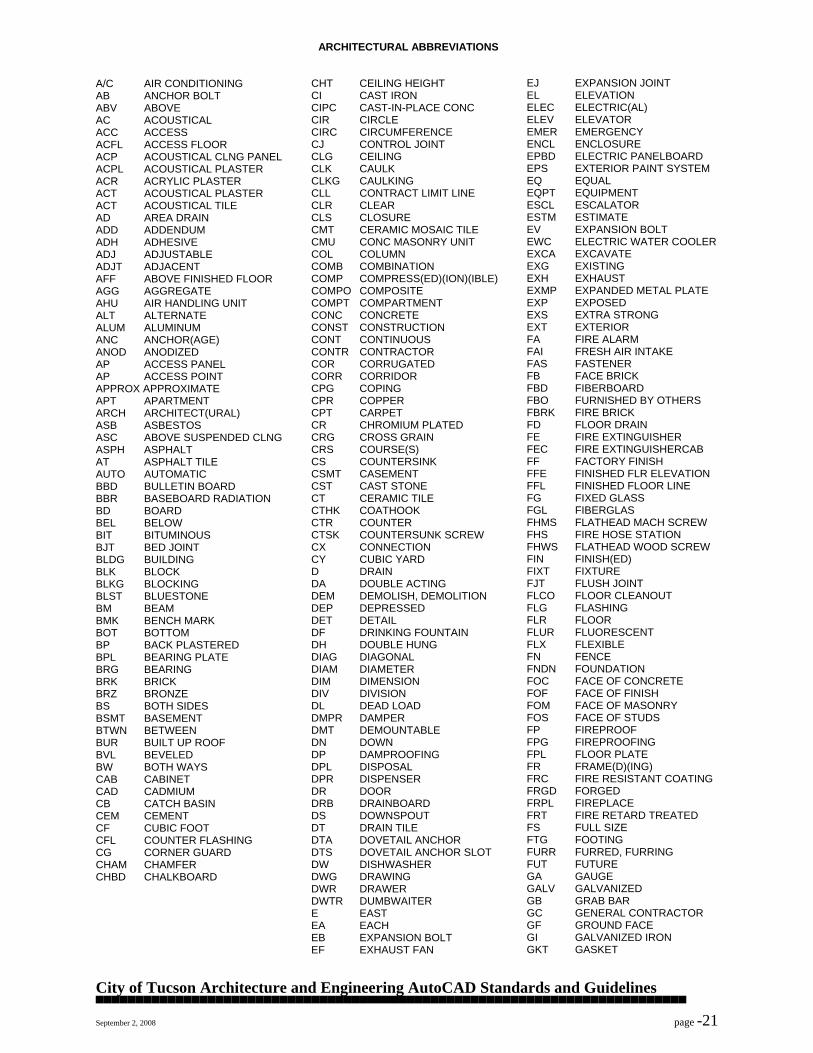
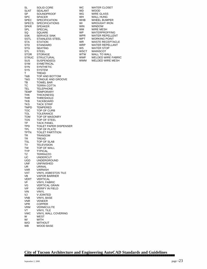
ARCHITECTURAL ABBREVIATIONS
A/C AIR CONDITIONING AB ANCHOR BOLT ABV ABOVE AC ACOUSTICAL ACC ACCESS ACFL ACCESS FLOOR ACP ACOUSTICAL CLNG PANEL ACPL ACOUSTICAL PLASTER ACR ACRYLIC PLASTER ACT ACOUSTICAL PLASTER ACT ACOUSTICAL TILE AD AREA DRAIN ADD ADDENDUM ADH ADHESIVE ADJ ADJUSTABLE ADJT ADJACENT AFF ABOVE FINISHED FLOOR AGG AGGREGATE AHU AIR HANDLING UNIT ALT ALTERNATE ALUM ALUMINUM ANC ANCHOR(AGE) ANOD ANODIZED AP ACCESS PANEL AP ACCESS POINT APPROX APPROXIMATE APT APARTMENT ARCH ARCHITECT(URAL) ASB ASBESTOS ASC ABOVE SUSPENDED CLNG ASPH ASPHALT AT ASPHALT TILE AUTO AUTOMATIC BBD BULLETIN BOARD BBR BASEBOARD RADIATION BD BOARD BEL BELOW BIT BITUMINOUS BJT BED JOINT BLDG BUILDING BLK BLOCK BLKG BLOCKING BLST BLUESTONE BM BEAM BMK BENCH MARK BOT BOTTOM BP BACK PLASTERED BPL BEARING PLATE BRG BEARING BRK BRICK BRZ BRONZE BS BOTH SIDES BSMT BASEMENT BTWN BETWEEN BUR BUILT UP ROOF BVL BEVELED BW BOTH WAYS CAB CABINET CAD CADMIUM CB CATCH BASIN CEM CEMENT CF CUBIC FOOT CFL COUNTER FLASHING CG CORNER GUARD CHAM CHAMFER CHBD CHALKBOARD
CHT CEILING HEIGHT CI CAST IRON CIPC CAST-IN-PLACE CONC CIR CIRCLE CIRC CIRCUMFERENCE CJ CONTROL JOINT CLG CEILING CLK CAULK CLKG CAULKING CLL CONTRACT LIMIT LINE CLR CLEAR CLS CLOSURE CMT CERAMIC MOSAIC TILE CMU CONC MASONRY UNIT COL COLUMN COMB COMBINATION COMP COMPRESS(ED)(ION)(IBLE) COMPO COMPOSITE COMPT COMPARTMENT CONC CONCRETE CONST CONSTRUCTION CONT CONTINUOUS CONTR CONTRACTOR COR CORRUGATED CORR CORRIDOR CPG COPING CPR COPPER CPT CARPET CR CHROMIUM PLATED CRG CROSS GRAIN CRS COURSE(S) CS COUNTERSINK CSMT CASEMENT CST CAST STONE CT CERAMIC TILE CTHK COATHOOK CTR COUNTER CTSK COUNTERSUNK SCREW CX CONNECTION CY CUBIC YARD D DRAIN DA DOUBLE ACTING DEM DEMOLISH, DEMOLITION DEP DEPRESSED DET DETAIL DF DRINKING FOUNTAIN DH DOUBLE HUNG DIAG DIAGONAL DIAM DIAMETER DIM DIMENSION DIV DIVISION DL DEAD LOAD DMPR DAMPER DMT DEMOUNTABLE DN DOWN DP DAMPROOFING DPL DISPOSAL DPR DISPENSER DR DOOR DRB DRAINBOARD DS DOWNSPOUT DT DRAIN TILE DTA DOVETAIL ANCHOR DTS DOVETAIL ANCHOR SLOT DW DISHWASHER DWG DRAWING DWR DRAWER DWTR DUMBWAITER E EAST EA EACH EB EXPANSION BOLT EF EXHAUST FAN
EJ EXPANSION JOINT EL ELEVATION ELEC ELECTRIC(AL) ELEV ELEVATOR EMER EMERGENCY ENCL ENCLOSURE EPBD ELECTRIC PANELBOARD EPS EXTERIOR PAINT SYSTEM EQ EQUAL EQPT EQUIPMENT ESCL ESCALATOR ESTM ESTIMATE EV EXPANSION BOLT EWC ELECTRIC WATER COOLER EXCA EXCAVATE EXG EXISTING EXH EXHAUST EXMP EXPANDED METAL PLATE EXP EXPOSED EXS EXTRA STRONG EXT EXTERIOR FA FIRE ALARM FAI FRESH AIR INTAKE FAS FASTENER FB FACE BRICK FBD FIBERBOARD FBO FURNISHED BY OTHERS FBRK FIRE BRICK FD FLOOR DRAIN FE FIRE EXTINGUISHER FEC FIRE EXTINGUISHERCAB FF FACTORY FINISH FFE FINISHED FLR ELEVATION FFL FINISHED FLOOR LINE FG FIXED GLASS FGL FIBERGLAS FHMS FLATHEAD MACH SCREW FHS FIRE HOSE STATION FHWS FLATHEAD WOOD SCREW FIN FINISH(ED) FIXT FIXTURE FJT FLUSH JOINT FLCO FLOOR CLEANOUT FLG FLASHING FLR FLOOR FLUR FLUORESCENT FLX FLEXIBLE FN FENCE FNDN FOUNDATION FOC FACE OF CONCRETE FOF FACE OF FINISH FOM FACE OF MASONRY FOS FACE OF STUDS FP FIREPROOF FPG FIREPROOFING FPL FLOOR PLATE FR FRAME(D)(ING) FRC FIRE RESISTANT COATING FRGD FORGED FRPL FIREPLACE FRT FIRE RETARD TREATED FS FULL SIZE FTG FOOTING FURR FURRED, FURRING FUT FUTURE GA GAUGE GALV GALVANIZED GB GRAB BAR GC GENERAL CONTRACTOR GF GROUND FACE GI GALVANIZED IRON GKT GASKET
City of Tucson Architecture and Engineering AutoCAD Standards and Guidelines ▀▀▀▀▀▀▀▀▀▀▀▀▀▀▀▀▀▀▀▀▀▀▀▀▀▀▀▀▀▀▀▀▀▀▀▀▀▀▀▀▀▀▀▀▀▀▀▀▀▀▀▀▀▀▀▀▀▀▀▀▀▀▀▀▀▀▀▀▀▀▀▀▀▀ September 2, 2008 page -22
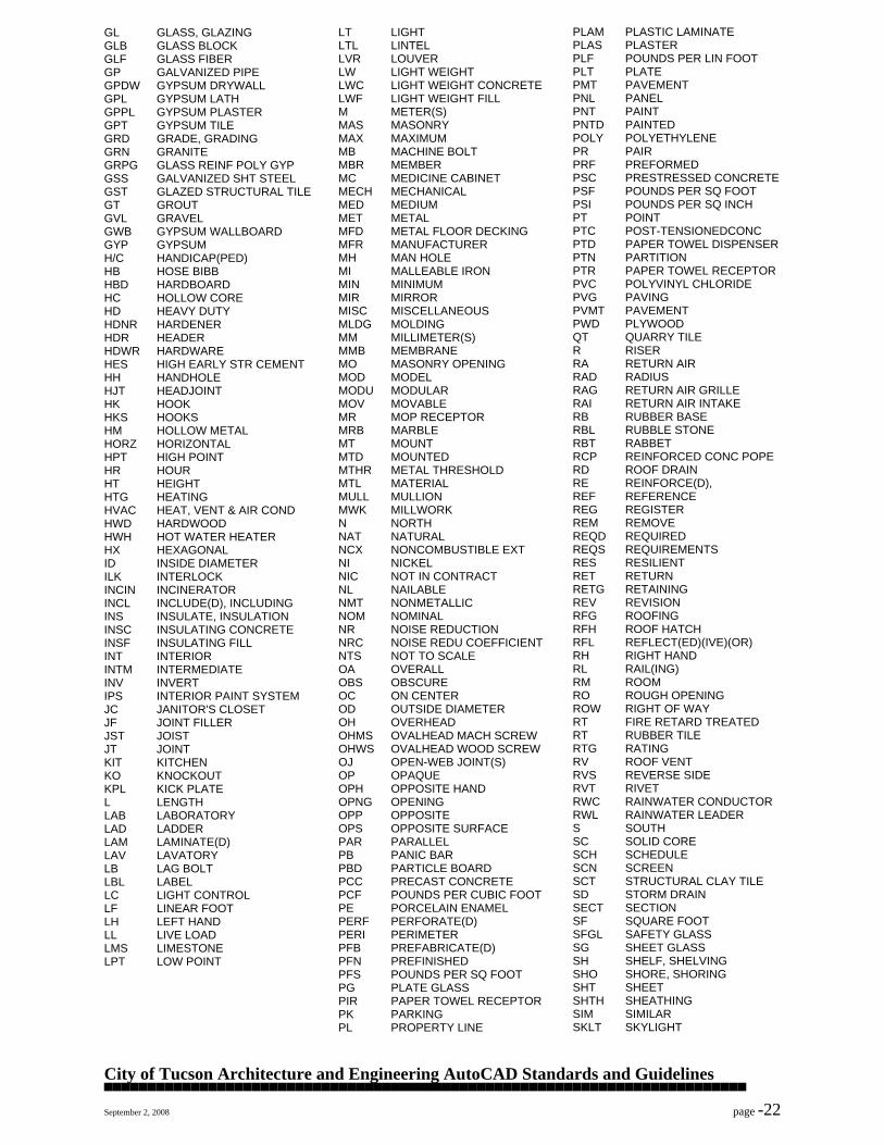
GL GLASS, GLAZING GLB GLASS BLOCK GLF GLASS FIBER GP GALVANIZED PIPE GPDW GYPSUM DRYWALL GPL GYPSUM LATH GPPL GYPSUM PLASTER GPT GYPSUM TILE GRD GRADE, GRADING GRN GRANITE GRPG GLASS REINF POLY GYP GSS GALVANIZED SHT STEEL GST GLAZED STRUCTURAL TILE GT GROUT GVL GRAVEL GWB GYPSUM WALLBOARD GYP GYPSUM H/C HANDICAP(PED) HB HOSE BIBB HBD HARDBOARD HC HOLLOW CORE HD HEAVY DUTY HDNR HARDENER HDR HEADER HDWR HARDWARE HES HIGH EARLY STR CEMENT HH HANDHOLE HJT HEADJOINT HK HOOK HKS HOOKS HM HOLLOW METAL HORZ HORIZONTAL HPT HIGH POINT HR HOUR HT HEIGHT HTG HEATING HVAC HEAT, VENT & AIR COND HWD HARDWOOD HWH HOT WATER HEATER HX HEXAGONAL ID INSIDE DIAMETER ILK INTERLOCK INCIN INCINERATOR INCL INCLUDE(D), INCLUDING INS INSULATE, INSULATION INSC INSULATING CONCRETE INSF INSULATING FILL INT INTERIOR INTM INTERMEDIATE INV INVERT IPS INTERIOR PAINT SYSTEM JC JANITOR'S CLOSET JF JOINT FILLER JST JOIST JT JOINT KIT KITCHEN KO KNOCKOUT KPL KICK PLATE L LENGTH LAB LABORATORY LAD LADDER LAM LAMINATE(D) LAV LAVATORY LB LAG BOLT LBL LABEL LC LIGHT CONTROL LF LINEAR FOOT LH LEFT HAND LL LIVE LOAD LMS LIMESTONE LPT LOW POINT
LT LIGHT LTL LINTEL LVR LOUVER LW LIGHT WEIGHT LWC LIGHT WEIGHT CONCRETE LWF LIGHT WEIGHT FILL M METER(S) MAS MASONRY MAX MAXIMUM MB MACHINE BOLT MBR MEMBER MC MEDICINE CABINET MECH MECHANICAL MED MEDIUM MET METAL MFD METAL FLOOR DECKING MFR MANUFACTURER MH MAN HOLE MI MALLEABLE IRON MIN MINIMUM MIR MIRROR MISC MISCELLANEOUS MLDG MOLDING MM MILLIMETER(S) MMB MEMBRANE MO MASONRY OPENING MOD MODEL MODU MODULAR MOV MOVABLE MR MOP RECEPTOR MRB MARBLE MT MOUNT MTD MOUNTED MTHR METAL THRESHOLD MTL MATERIAL MULL MULLION MWK MILLWORK N NORTH NAT NATURAL NCX NONCOMBUSTIBLE EXT NI NICKEL NIC NOT IN CONTRACT NL NAILABLE NMT NONMETALLIC NOM NOMINAL NR NOISE REDUCTION NRC NOISE REDU COEFFICIENT NTS NOT TO SCALE OA OVERALL OBS OBSCURE OC ON CENTER OD OUTSIDE DIAMETER OH OVERHEAD OHMS OVALHEAD MACH SCREW OHWS OVALHEAD WOOD SCREW OJ OPEN-WEB JOINT(S) OP OPAQUE OPH OPPOSITE HAND OPNG OPENING OPP OPPOSITE OPS OPPOSITE SURFACE PAR PARALLEL PB PANIC BAR PBD PARTICLE BOARD PCC PRECAST CONCRETE PCF POUNDS PER CUBIC FOOT PE PORCELAIN ENAMEL PERF PERFORATE(D) PERI PERIMETER PFB PREFABRICATE(D) PFN PREFINISHED PFS POUNDS PER SQ FOOT PG PLATE GLASS PIR PAPER TOWEL RECEPTOR PK PARKING PL PROPERTY LINE
PLAM PLASTIC LAMINATE PLAS PLASTER PLF POUNDS PER LIN FOOT PLT PLATE PMT PAVEMENT PNL PANEL PNT PAINT PNTD PAINTED POLY POLYETHYLENE PR PAIR PRF PREFORMED PSC PRESTRESSED CONCRETE PSF POUNDS PER SQ FOOT PSI POUNDS PER SQ INCH PT POINT PTC POST-TENSIONEDCONC PTD PAPER TOWEL DISPENSER PTN PARTITION PTR PAPER TOWEL RECEPTOR PVC POLYVINYL CHLORIDE PVG PAVING PVMT PAVEMENT PWD PLYWOOD QT QUARRY TILE R RISER RA RETURN AIR RAD RADIUS RAG RETURN AIR GRILLE RAI RETURN AIR INTAKE RB RUBBER BASE RBL RUBBLE STONE RBT RABBET RCP REINFORCED CONC POPE RD ROOF DRAIN RE REINFORCE(D), REF REFERENCE REG REGISTER REM REMOVE REQD REQUIRED REQS REQUIREMENTS RES RESILIENT RET RETURN RETG RETAINING REV REVISION RFG ROOFING RFH ROOF HATCH RFL REFLECT(ED)(IVE)(OR) RH RIGHT HAND RL RAIL(ING) RM ROOM RO ROUGH OPENING ROW RIGHT OF WAY RT FIRE RETARD TREATED RT RUBBER TILE RTG RATING RV ROOF VENT RVS REVERSE SIDE RVT RIVET RWC RAINWATER CONDUCTOR RWL RAINWATER LEADER S SOUTH SC SOLID CORE SCH SCHEDULE SCN SCREEN SCT STRUCTURAL CLAY TILE SD STORM DRAIN SECT SECTION SF SQUARE FOOT SFGL SAFETY GLASS SG SHEET GLASS SH SHELF, SHELVING SHO SHORE, SHORING SHT SHEET SHTH SHEATHING SIM SIMILAR SKLT SKYLIGHT
General Services Department
Architecture & Engineering Division
Project Manager’s Manual
SCHEMATIC DESIGN PHASE
ISSUED DATE REFERENCE PERSON REVISION # REVISION DATE
9/1/2007 A&E Administrator ADA Update 11/29/2013
Revised Pages PAGE
2 & 3 ADA Related only Page 5 of 7
Schematic Design Rev 11-29-13 MD.doc Page 5 of 7 12/5/2013
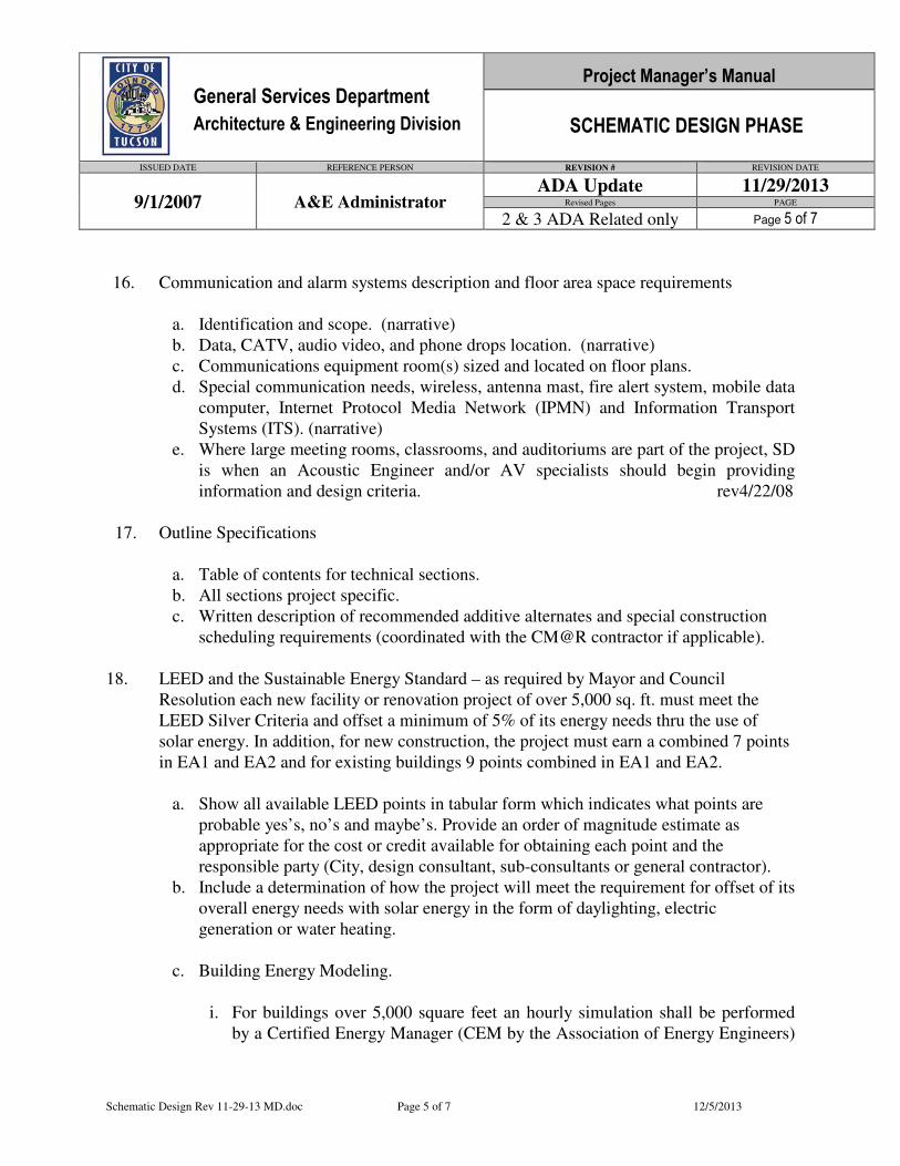
16. Communication and alarm systems description and floor area space requirements
a. Identification and scope. (narrative)
b. Data, CATV, audio video, and phone drops location. (narrative)
c. Communications equipment room(s) sized and located on floor plans.
d. Special communication needs, wireless, antenna mast, fire alert system, mobile data
computer, Internet Protocol Media Network (IPMN) and Information Transport
Systems (ITS). (narrative)
e. Where large meeting rooms, classrooms, and auditoriums are part of the project, SD
is when an Acoustic Engineer and/or AV specialists should begin providing
information and design criteria. rev4/22/08
17. Outline Specifications
a. Table of contents for technical sections.
b. All sections project specific.
c. Written description of recommended additive alternates and special construction
scheduling requirements (coordinated with the CM@R contractor if applicable).
18. LEED and the Sustainable Energy Standard – as required by Mayor and Council
Resolution each new facility or renovation project of over 5,000 sq. ft. must meet the
LEED Silver Criteria and offset a minimum of 5% of its energy needs thru the use of
solar energy. In addition, for new construction, the project must earn a combined 7 points
in EA1 and EA2 and for existing buildings 9 points combined in EA1 and EA2.
a. Show all available LEED points in tabular form which indicates what points are
probable yes’s, no’s and maybe’s. Provide an order of magnitude estimate as
appropriate for the cost or credit available for obtaining each point and the
responsible party (City, design consultant, sub-consultants or general contractor).
b. Include a determination of how the project will meet the requirement for offset of its
overall energy needs with solar energy in the form of daylighting, electric
generation or water heating.
c. Building Energy Modeling.
i. For buildings over 5,000 square feet an hourly simulation shall be performed
by a Certified Energy Manager (CEM by the Association of Energy Engineers)
City of Tucson Architecture and Engineering AutoCAD Standards and Guidelines ▀▀▀▀▀▀▀▀▀▀▀▀▀▀▀▀▀▀▀▀▀▀▀▀▀▀▀▀▀▀▀▀▀▀▀▀▀▀▀▀▀▀▀▀▀▀▀▀▀▀▀▀▀▀▀▀▀▀▀▀▀▀▀▀▀▀▀▀▀▀▀▀▀▀ September 2, 2008 page -23
SL SOLID CORE SLNT SEALANT SP SOUNDPROOF SPC SPACER SPEC SPECIFICATION SPECS SPECIFICATIONS SPKR SPEAKER SPL SPECIAL SQ SQUARE SSK SERVICE SINK SSTL STAINLESS STEEL STA STATION STD STANDARD STG SEATING STL STEEL STOR STORAGE STRUC STRUCTURAL SUS SUSPEND(ED) SYM SYMETRICAL SYN SYNTHETIC SYS SYSTEM T TREAD T&B TOP AND BOTTOM T&G TONGUE AND GROOVE TB TOWEL BAR TC TERRA COTTA TEL TELEPHONE TEMP TEMPORARY THK THICK(NESS) THR THRESHOLD TKB TACKBOARD TKS TACK STRIP TMPD TEMPERED TOC TOP OF CURB TOL TOLERANCE TOM TOP OF MASONRY TOS TOP OF STEEL TP TACK PANEL TPD TOILET PAPER DISPENSER TPL TOP OF PLATE TPTN TOILET PARTITION TR TRANSOM TR TREAD TSL TOP OF SLAB TV TELEVISION TW TOP OF WALL TYP TYPICAL TZ TERRAZZO UC UNDERCUT UGD UNDERGROUND UNF UNFINISHED UR URINAL VAR VARNISH VAT VINYL ASBESTOS TILE VB VAPOR BARRIER VERT VERTICAL VF VINYL FABRIC VG VERTICAL GRAIN VIF VERIFY IN FIELD VIN VINYL VJ V-JOINTED VNB VINYL BASE VNR VENEER VPR COPPER VRM VERMICULITE VT VINYL TILE VWC VINYL WALL COVERING W WEST W/ WITH W/O WITHOUT WB WOOD BASE
WC WATER CLOSET WD WOOD WG WIRE GLASS WH WALL HUNG WHB WHEEL BUMPER WI WROUGHT IRON WIN WINDOW WM WIRE MESH WP WATERPROFFING WPR WATER REPELLENT WPT WORKING POINT WR WASTE RECEPTACLE WRP WATER REPELLANT WS WATER STOP WSCT WAINSCOT WTW WALL TO WALL WWF WELDED WIRE FABRIC WWM WELDED WIRE MESH
City of Tucson Architecture and Engineering AutoCAD Standards and Guidelines ▀▀▀▀▀▀▀▀▀▀▀▀▀▀▀▀▀▀▀▀▀▀▀▀▀▀▀▀▀▀▀▀▀▀▀▀▀▀▀▀▀▀▀▀▀▀▀▀▀▀▀▀▀▀▀▀▀▀▀▀▀▀▀▀▀▀▀▀▀▀▀▀▀▀ September 2, 2008 page -24
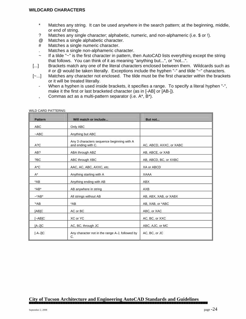
WILDCARD CHARACTERS
* Matches any string. It can be used anywhere in the search pattern; at the beginning, middle, or end of string.
? Matches any single character; alphabetic, numeric, and non-alphameric (i.e. $ or !). @ Matches a single alphabetic character. # Matches a single numeric character. . Matches a single non-alphameric character. ~ If a tilde "~" is the first character in pattern, then AutoCAD lists everything except the string
that follows. You can think of it as meaning "anything but...", or "not...". [...] Brackets match any one of the literal characters enclosed between them. Wildcards such as
# or @ would be taken literally. Exceptions include the hyphen "-" and tilde "~" characters. [~...] Matches any character not enclosed. The tilde must be the first character within the brackets
or it will be treated literally. - When a hyphen is used inside brackets, it specifies a range. To specify a literal hyphen "-",
make it the first or last bracketed character (as in [-AB] or [AB-]). , Commas act as a multi-pattern separator (i.e. A*, B*).
WILD CARD PATTERNS:
Pattern
Will match or include...
But not...
ABC
Only ABC
~ABC
Anything but ABC
A?C
Any 3 characters sequence beginning with A and ending with C.
AC, ABCD, AXXC, or XABC
AB?
ABA through ABZ
AB, ABCE, or XAB
?BC
ABC through XBC
AB, ABCD, BC, or XXBC
A*C
AAC, AC, ABC, AXXC, etc.
XA or ABCD
A*
Anything starting with A
XAAA
*AB
Anything ending with AB
ABX
*AB*
AB anywhere in string
AXB
~*AB*
All strings without AB
AB, ABX, XAB, or XABX
'*AB
*AB
AB, XAB, or *ABC
[AB]C
AC or BC
ABC, or XAC
[~AB]C
XC or YC
AC, BC, or XXC
[A-J]C
AC, BC, through JC
ABC, AJC, or MC
[-A-J]C
Any character not in the range A-J, followed by C.
AC, BC, or JC
City of Tucson Architecture and Engineering AutoCAD Standards and Guidelines ▀▀▀▀▀▀▀▀▀▀▀▀▀▀▀▀▀▀▀▀▀▀▀▀▀▀▀▀▀▀▀▀▀▀▀▀▀▀▀▀▀▀▀▀▀▀▀▀▀▀▀▀▀▀▀▀▀▀▀▀▀▀▀▀▀▀▀▀▀▀▀▀▀▀ September 2, 2008 page -25
AUTOCAD GENERAL ERROR RECOVERY AND POSSIBLE CAUSES Almost all errors are caused by corruption of one of the following: 1. The drawing file that AutoCAD is reading 2. The temporary files that AutoCAD has generated 3. AutoCAD's working environment under MS WINDOWS. Drawing files can be corrupted due to several reasons: disk drives may need cleaning and alignment, a voltage spike during a read or write to disk can corrupt data, the disk drive may be highly fragmented, over-heated, etc. Remember that you cannot recover the drawing file in question using a binary/hex editor to patch the data, or one of the popular unerase utilities under MS-DOS, like Norton Utilities. Norton's Disk Doctor also will not recover corrupted drawing files since it only relocates all the readable bytes to another area of the disk, ignoring the unreadable ones. AutoCAD drawing files are extremely sensitive and as much as one misplaced bytes can render the file unreadable. The hex dump that follows the Error message is merely a traceback of internal addresses, telling the AutoCAD programmer the sequence of most recent function calls that preceded the error. It holds little significance for the general customer. Temporary files can be corrupted at run-time due to the reasons above, and also due to improper configuration. For example, if you are running AutoCAD on a machine with EXTended memory, ensure that AutoCAD has detected the presence of any RAM disks or partitioned EXPanded memory. If it has failed to do so, then any data that AutoCAD has paged into its Extended I/O page space runs the risk of being over-written by other information that is being written to the RAM disk or the "other memory partition". Under MS-DOS, AutoCAD establishes and maintains a tight working environment consisting of memory blocks, data resources and software interrupts. Should an ill-behaved TSR program or a device driver alter this carefully maintained state without AutoCAD's knowledge, any data that AutoCAD is operating on runs the risk of being corrupted during execution. Whenever these error messages occur, AutoCAD is almost certainly reporting a genuine case of data or environment corruption. On rare occasion, this may point back to a software bug within AutoCAD. These cases are almost always repeatable and occur due to a specific sequence of events; e.g., if drawing a circle and trimming it to 1/4" of its radius always generates an error in any drawing, then you may have discovered a software bug. What do I do if I encounter one of these errors ? First of all, don't panic. If the drawing file itself is corrupted, you will encounter the error while calling up the drawing on any machine or copy of AutoCAD. In this situation, you can either: return to the backup of the drawing file in question (backing up your data on a regular basis is critical), or use the procedure outlined in Appendix F of the Reference Manual under "Disaster Handling".
City of Tucson Architecture and Engineering AutoCAD Standards and Guidelines ▀▀▀▀▀▀▀▀▀▀▀▀▀▀▀▀▀▀▀▀▀▀▀▀▀▀▀▀▀▀▀▀▀▀▀▀▀▀▀▀▀▀▀▀▀▀▀▀▀▀▀▀▀▀▀▀▀▀▀▀▀▀▀▀▀▀▀▀▀▀▀▀▀▀ September 2, 2008 page -26
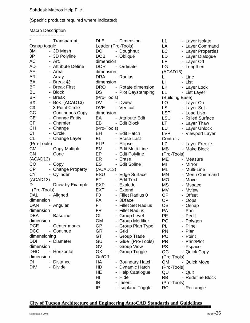
Softdesk Macros Help File (Specific products required where indicated) Macro Description ----------------------- '' - Transparent Osnap toggle 3M - 3D Mesh 3P - 3D Polyline AC - Arc AD - Attribute Define AE - Area AR - Array BA - Break @ BF - Break First BL - Block BR - Break BX - Box (ACAD13) C3 - 3 Point Circle CC - Continuous Copy CE - Change Entity CF - Chamfer CH - Change CI - Circle CL - Change Layer (Pro-Tools) CM - Copy Multiple CN - Cone (ACAD13) CO - Copy CP - Change Property CY - Cylinder (ACAD13) D - Draw by Example (Pro-Tools) DAL - Aligned dimension DAN - Angular dimension DBA - Baseline dimension DCE - Center marks DCO - Continue dimensioning DDI - Diameter dimension DHO - Horizontal dimension DI - Distance DIV - Divide
DLE - Dimension Leader (Pro-Tools) DO - Doughnut DOB - Oblique dimension DOR - Ordinate dimension DRA - Radius dimension DRO - Rotate dimension DS - Plot Daystamping (Pro-Tools) DV - Dview DVE - Vertical dimension EA - Attribute Edit EB - Edit Block (Pro-Tools) EH - Edit Hatch EL - Erase Last ELP - Ellipse EM - Edit Multi-Line EP - Edit Polyline ER - Erase ES - Edit Spline (ACAD13) ESU - Edge Surface ET - Edit Text EXP - Explode EXT - Extend F0 - Fillet Radius 0 FA - 3Dface FI - Fillet Set Radius FR - Fillet Radius GL - Group Level GM - Group Modifier GP - Group Plan Type GR - Grid GT - Group Trade GU - Glue (Pro-Tools) GV - Group View GX - Group Toggle On/Off HA - Boundary Hatch HD - Dynamic Hatch HE - Help Catalogue HI - Hide IN - Insert IP - Isoplane Toggle
L1 - Layer Isolate LA - Layer Command LC - Layer Properties LD - Layer Dialogue LF - Layer Off LG - Lengthen (ACAD13) L - Line LI - List LK - Layer Lock LL - List Layer (Building Base) LO - Layer On LS - Layer Set LSP - Load Lisp LSU - Ruled Surface LT - Layer Thaw LU - Layer Unlock LVP - Viewport Layer Controls LZ - Layer Freeze MB - Make Block (Pro-Tools) ME - Measure MI - Mirror ML - Multi-Line MN - Menu Command MO - Move MS - Mspace MV - Mview OF - Offset OP - Oops OS - Osnap PA - Pan PE - Pedit PG - Polygon PL - Pline PN - Plan PO - Point PR - Print/Plot PS - Pspace QC - Quick Copy (Pro-Tools) QM - Quick Move (Pro-Tools) QU - Quit RB - Redefine Block (Pro-Tools) RC - Rectangle
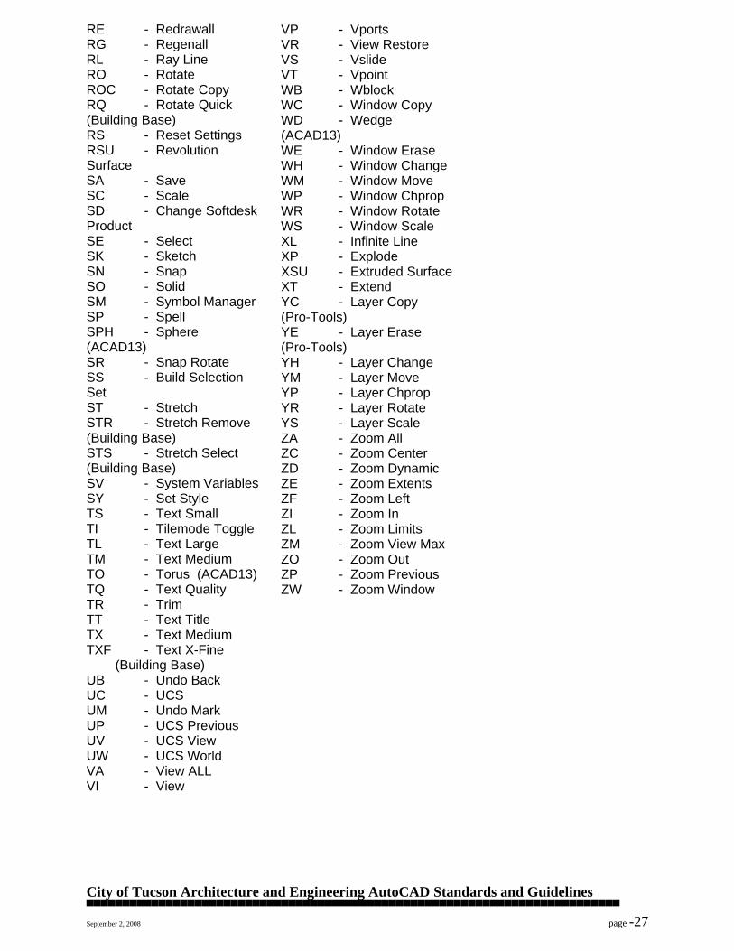
City of Tucson Architecture and Engineering AutoCAD Standards and Guidelines ▀▀▀▀▀▀▀▀▀▀▀▀▀▀▀▀▀▀▀▀▀▀▀▀▀▀▀▀▀▀▀▀▀▀▀▀▀▀▀▀▀▀▀▀▀▀▀▀▀▀▀▀▀▀▀▀▀▀▀▀▀▀▀▀▀▀▀▀▀▀▀▀▀▀ September 2, 2008 page -27
RE - Redrawall RG - Regenall RL - Ray Line RO - Rotate ROC - Rotate Copy RQ - Rotate Quick (Building Base) RS - Reset Settings RSU - Revolution Surface SA - Save SC - Scale SD - Change Softdesk Product SE - Select SK - Sketch SN - Snap SO - Solid SM - Symbol Manager SP - Spell SPH - Sphere (ACAD13) SR - Snap Rotate SS - Build Selection Set ST - Stretch STR - Stretch Remove (Building Base) STS - Stretch Select (Building Base) SV - System Variables SY - Set Style TS - Text Small TI - Tilemode Toggle TL - Text Large TM - Text Medium TO - Torus (ACAD13) TQ - Text Quality TR - Trim TT - Text Title TX - Text Medium TXF - Text X-Fine (Building Base) UB - Undo Back UC - UCS UM - Undo Mark UP - UCS Previous UV - UCS View UW - UCS World VA - View ALL VI - View
VP - Vports VR - View Restore VS - Vslide VT - Vpoint WB - Wblock WC - Window Copy WD - Wedge (ACAD13) WE - Window Erase WH - Window Change WM - Window Move WP - Window Chprop WR - Window Rotate WS - Window Scale XL - Infinite Line XP - Explode XSU - Extruded Surface XT - Extend YC - Layer Copy (Pro-Tools) YE - Layer Erase (Pro-Tools) YH - Layer Change YM - Layer Move YP - Layer Chprop YR - Layer Rotate YS - Layer Scale ZA - Zoom All ZC - Zoom Center ZD - Zoom Dynamic ZE - Zoom Extents ZF - Zoom Left ZI - Zoom In ZL - Zoom Limits ZM - Zoom View Max ZO - Zoom Out ZP - Zoom Previous ZW - Zoom Window
City of Tucson Architecture and Engineering AutoCAD Standards and Guidelines ▀▀▀▀▀▀▀▀▀▀▀▀▀▀▀▀▀▀▀▀▀▀▀▀▀▀▀▀▀▀▀▀▀▀▀▀▀▀▀▀▀▀▀▀▀▀▀▀▀▀▀▀▀▀▀▀▀▀▀▀▀▀▀▀▀▀▀▀▀▀▀▀▀▀ September 2, 2008 page -28
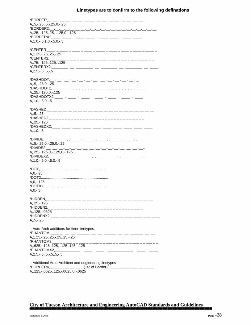
Linetypes are to confirm to the following definations *BORDER,__ __ . __ __ . __ __ . __ __ . __ __ . __ __ . __ __ . __ __ . A,.5,-.25,.5,-.25,0,-.25 *BORDER2,__.__.__.__.__.__.__.__.__.__.__.__.__.__.__.__.__.__.__.__.__ A,.25,-.125,.25,-.125,0,-.125 *BORDERX2,____ ____ . ____ ____ . ____ ____ . ____ ____ . A,1.0,-.5,1.0,-.5,0,-.5 *CENTER,____ _ ____ _ ____ _ ____ _ ____ _ ____ _ ____ _ ____ _ ____ _ A,1.25,-.25,.25,-.25 *CENTER2,___ _ ___ _ ___ _ ___ _ ___ _ ___ _ ___ _ ___ _ ___ _ ___ _ _ A,.75,-.125,.125,-.125 *CENTERX2,________ __ ________ __ ________ __ ________ __ ____ A,2.5,-.5,.5,-.5 *DASHDOT,__ . __ . __ . __ . __ . __ . __ . __ . __ . __ . __ . __ . _ A,.5,-.25,0,-.25 *DASHDOT2,_._._._._._._._._._._._._._._._._._._._._._._._._._._._._._. A,.25,-.125,0,-.125 *DASHDOTX2,____ . ____ . ____ . ____ . ____ . ____ . ____ A,1.0,-.5,0,-.5 *DASHED,__ __ __ __ __ __ __ __ __ __ __ __ __ __ __ __ __ __ __ __ __ A,.5,-.25 *DASHED2,_ _ _ _ _ _ _ _ _ _ _ _ _ _ _ _ _ _ _ _ _ _ _ _ _ _ _ _ _ _ _ A,.25,-.125 *DASHEDX2,____ ____ ____ ____ ____ ____ ____ ____ ____ ____ A,1.0,-.5 *DIVIDE,____ . . ____ . . ____ . . ____ . . ____ . . ____ . . ____ . . A,.5,-.25,0,-.25,0,-.25 *DIVIDE2,__..__..__..__..__..__..__..__..__..__..__..__..__..__..__..__.. A,.25,-.125,0,-.125,0,-.125 *DIVIDEX2,________ . . ________ . . ________ . . ________ . . A,1.0,-.5,0,-.5,0,-.5 *DOT,. . . . . . . . . . . . . . . . . . . . . . . . . . . . . . . . . A,0,-.25 *DOT2,................................................................ A,0,-.125 *DOTX2,. . . . . . . . . . . . . . . . . . . . . A,0,-.5 *HIDDEN,__ __ __ __ __ __ __ __ __ __ __ __ __ __ __ __ __ __ __ __ __ A,.25,-.125 *HIDDEN2,_ _ _ _ _ _ _ _ _ _ _ _ _ _ _ _ _ _ _ _ _ _ _ _ _ _ _ _ _ _ _ A,.125,-.0625 *HIDDENX2,____ ____ ____ ____ ____ ____ ____ ____ ____ ____ ____ ____ A,.5,-.25 ;; Auto-Arch additions for finer linetypes. *PHANTOM,______ __ __ ______ __ __ ______ __ __ ______ __ __ A,1.25,-.25,.25,-.25,.25,-.25 *PHANTOM2,___ _ _ ___ _ _ ___ _ _ ___ _ _ ___ _ _ ___ _ _ ___ _ _ ___ _ _ A,.625,-.125,.125,-.125,.125,-.125 *PHANTOMX2,____________ ____ ____ ____________ ____ ____ A,2.5,-.5,.5,-.5,.5,-.5 ;; Additional Auto-Architect and engineering linetypes *BORDER4,__.__.__.__.__.__._ (1/2 of Border2) _.__.__.__.__.__.__.__.__ A,.125,-.0625,.125,-.0625,0,-.0625
City of Tucson Architecture and Engineering AutoCAD Standards and Guidelines ▀▀▀▀▀▀▀▀▀▀▀▀▀▀▀▀▀▀▀▀▀▀▀▀▀▀▀▀▀▀▀▀▀▀▀▀▀▀▀▀▀▀▀▀▀▀▀▀▀▀▀▀▀▀▀▀▀▀▀▀▀▀▀▀▀▀▀▀▀▀▀▀▀▀ September 2, 2008 page -29
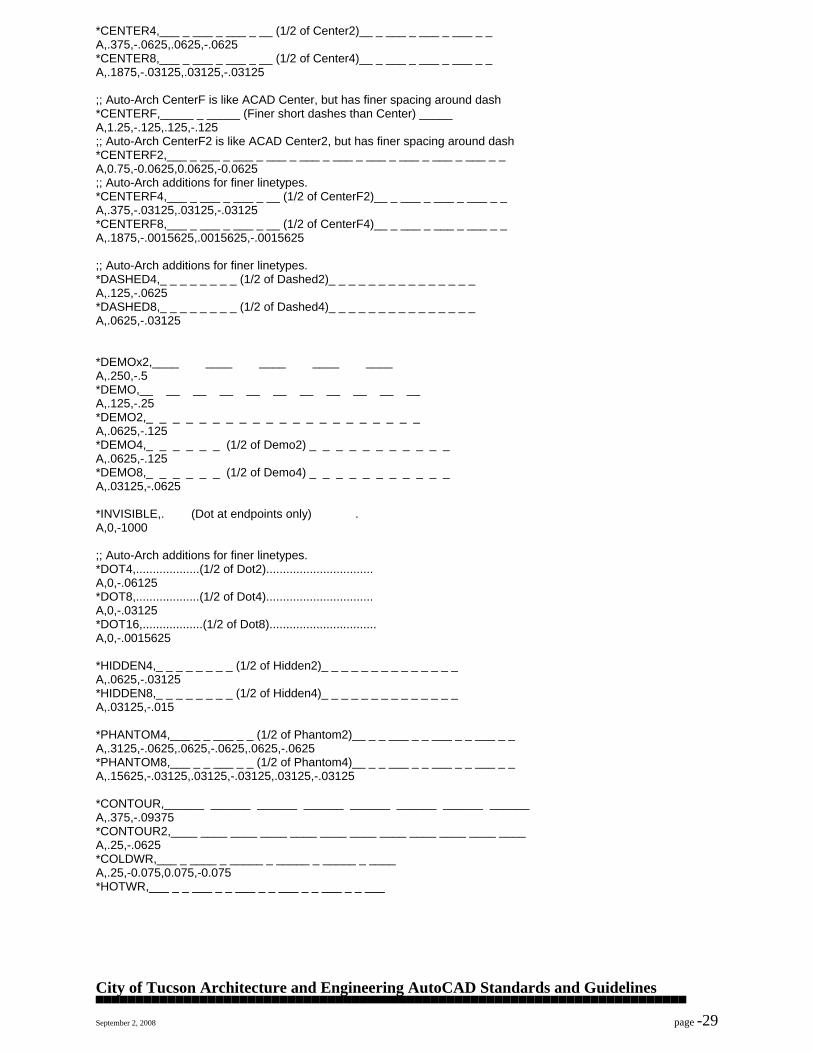
*CENTER4,___ _ ___ _ ___ _ __ (1/2 of Center2)__ _ ___ _ ___ _ ___ _ _ A,.375,-.0625,.0625,-.0625 *CENTER8,___ _ ___ _ ___ _ __ (1/2 of Center4)__ _ ___ _ ___ _ ___ _ _ A,.1875,-.03125,.03125,-.03125 ;; Auto-Arch CenterF is like ACAD Center, but has finer spacing around dash *CENTERF,_____ _ _____ (Finer short dashes than Center) _____ A,1.25,-.125,.125,-.125 ;; Auto-Arch CenterF2 is like ACAD Center2, but has finer spacing around dash *CENTERF2,___ _ ___ _ ___ _ ___ _ ___ _ ___ _ ___ _ ___ _ ___ _ ___ _ _ A,0.75,-0.0625,0.0625,-0.0625 ;; Auto-Arch additions for finer linetypes. *CENTERF4,___ _ ___ _ ___ _ __ (1/2 of CenterF2)__ _ ___ _ ___ _ ___ _ _ A,.375,-.03125,.03125,-.03125 *CENTERF8,___ _ ___ _ ___ _ __ (1/2 of CenterF4)__ _ ___ _ ___ _ ___ _ _ A,.1875,-.0015625,.0015625,-.0015625 ;; Auto-Arch additions for finer linetypes. *DASHED4,_ _ _ _ _ _ _ _ (1/2 of Dashed2)_ _ _ _ _ _ _ _ _ _ _ _ _ _ _ A,.125,-.0625 *DASHED8,_ _ _ _ _ _ _ _ (1/2 of Dashed4)_ _ _ _ _ _ _ _ _ _ _ _ _ _ _ A,.0625,-.03125 *DEMOx2,____ ____ ____ ____ ____ A,.250,-.5 *DEMO,__ __ __ __ __ __ __ __ __ __ __ A,.125,-.25 *DEMO2,_ _ _ _ _ _ _ _ _ _ _ _ _ _ _ _ _ _ _ _ _ A,.0625,-.125 *DEMO4,_ _ _ _ _ _ (1/2 of Demo2) _ _ _ _ _ _ _ _ _ _ _ A,.0625,-.125 *DEMO8,_ _ _ _ _ _ (1/2 of Demo4) _ _ _ _ _ _ _ _ _ _ _ A,.03125,-.0625 *INVISIBLE,. (Dot at endpoints only) . A,0,-1000 ;; Auto-Arch additions for finer linetypes. *DOT4,...................(1/2 of Dot2)................................ A,0,-.06125 *DOT8,...................(1/2 of Dot4)................................ A,0,-.03125 *DOT16,..................(1/2 of Dot8)................................ A,0,-.0015625 *HIDDEN4,_ _ _ _ _ _ _ _ (1/2 of Hidden2)_ _ _ _ _ _ _ _ _ _ _ _ _ _ A,.0625,-.03125 *HIDDEN8,_ _ _ _ _ _ _ _ (1/2 of Hidden4)_ _ _ _ _ _ _ _ _ _ _ _ _ _ A,.03125,-.015 *PHANTOM4,___ _ _ ___ _ _ (1/2 of Phantom2)__ _ _ ___ _ _ ___ _ _ ___ _ _ A,.3125,-.0625,.0625,-.0625,.0625,-.0625 *PHANTOM8,___ _ _ ___ _ _ (1/2 of Phantom4)__ _ _ ___ _ _ ___ _ _ ___ _ _ A,.15625,-.03125,.03125,-.03125,.03125,-.03125 *CONTOUR,______ ______ ______ ______ ______ ______ ______ ______ A,.375,-.09375 *CONTOUR2,____ ____ ____ ____ ____ ____ ____ ____ ____ ____ ____ ____ A,.25,-.0625 *COLDWR,___ _ ____ _ _____ _ _____ _ _____ _ ____ A,.25,-0.075,0.075,-0.075 *HOTWR,___ _ _ ___ _ _ ___ _ _ ___ _ _ ___ _ _ ___
City of Tucson Architecture and Engineering AutoCAD Standards and Guidelines ▀▀▀▀▀▀▀▀▀▀▀▀▀▀▀▀▀▀▀▀▀▀▀▀▀▀▀▀▀▀▀▀▀▀▀▀▀▀▀▀▀▀▀▀▀▀▀▀▀▀▀▀▀▀▀▀▀▀▀▀▀▀▀▀▀▀▀▀▀▀▀▀▀▀ September 2, 2008 page -30
A,.25,-0.075,0.075,-0.075,0.075,-0.075 *HCW,_____ _ _ _ _____ _ _ _ _____ _ _ _ _____ A,1,-0.125,0.125,-0.125,0.125,-0.125,0.125,-0.125 *BOUNDARY,___________ __ __ ___________ __ __ ______ A,1.75,-0.125,0.125,-0.125,0.125,-0.125 *BOUNDARY2,______ _ _ ______ _ _ ______ _ _ ______ _ _ ______ A,1,-0.0625,0.0625,-0.0625,0.0625,-0.0625 *STREAM,_________ . . ___________ . . ___________ A,1,-0.125,0,-0.125,0,-0.125 *PNEUM,__ ___ ___ ___ ___ ___ ___ ___ ___ ___ __ A,0.2,-0.1,0.2,-0.1 *WASTE,__ __ __ __ __ __ __ __ __ __ __ __ __ __ A,.25,-.125 *2DASHES,____ _ _ _____ _ _ ____ _ _ ____ _ _ ____ A,0.75,-0.25,0.1,-0.25,0.1,-0.25 *EWIREUP,__ . __ . __ . __ . __ . __ . __ . __ .__ A,.25,-.075,0,-.075 *EWCELL,___ ___ . ___ ___ . __ __ . __ __ . __ __ A,.25,-.075,.25,-.075,0,-.075 ;; Additional linetype for details *EVENDASH,-- -- -- -- -- -- -- -- -- -- -- A,.125,-.125 ;; Additional Plumbing linetypes *DCW,Domestic Cold Water ___ _ ______________ _ ____ A,1.25,-0.06,0.08,-0.06 *DCW2,Domestic Cold Water __ _ ______ _ _____ _ ____ A,.625,-0.03,0.04,-0.03 *DCWX2,Domestic Cold Water ________ ___ __________ A,2.5,-0.12,0.16,-0.12 *DHW,Domestic Hot Water ___ _ _ ___________ _ _ ____ A,1.25,-0.06,0.08,-0.06,0.08,-0.06 *DHW2,Domestic Hot Water __ _ _ _____ _ _ ____ _ _ __ A,.625,-0.03,0.04,-0.03,0.04,-0.03 *DHWX2,Domestic Hot Water _____ ___ ___ ___ _____ A,2.5,-0.12,0.16,-0.12,0.16,-0.12 *DHWR,Domestic Hot Wtr Return _____ __ __ __ ________ A,1.25,-0.06,0.08,-0.06,0.08,-0.06,0.08,-0.06 *DHWR2,Domestic Hot Wtr Return ___ _ _ _ ____________ A,.625,-0.03,0.04,-0.03,0.04,-0.03,0.04,-0.03 *DHWRX2,Domestic Hot Wtr Return ____ ___ ____ ____ ____ A,2.5,-0.12,0.16,-0.12,0.16,-0.12,0.16,-0.12 *VENT,Sanitary Vent Pipe __ __ __ __ __ __ __ __ __ __ A,0.16,-0.08 *VENT2,Sanitary Vent Pipe _ _ _ _ _ _ _ _ _ _ _ _ _ _ _ A,0.08,-0.04 *VENTX2,Sanitary Vent Pipe ____ ____ ____ ___ A,0.32,-0.16 *COND,Steam Condensate __ __ __ __ __ __ __ __ __ __ __ A,0.16,-0.08 *COND2,Steam Condensate _ _ _ _ _ _ _ _ _ _ _ _ _ _ _ _ A,0.08,-0.04 *CONDX2,Steam Condensate ____ ____ ____ ____ A,0.32,-0.16
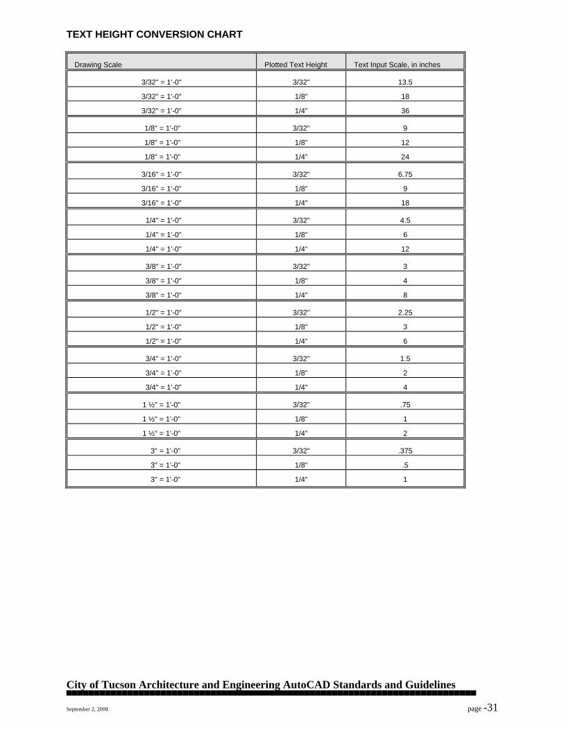
City of Tucson Architecture and Engineering AutoCAD Standards and Guidelines ▀▀▀▀▀▀▀▀▀▀▀▀▀▀▀▀▀▀▀▀▀▀▀▀▀▀▀▀▀▀▀▀▀▀▀▀▀▀▀▀▀▀▀▀▀▀▀▀▀▀▀▀▀▀▀▀▀▀▀▀▀▀▀▀▀▀▀▀▀▀▀▀▀▀ September 2, 2008 page -31
TEXT HEIGHT CONVERSION CHART
Drawing Scale
Plotted Text Height
Text Input Scale, in inches
3/32" = 1'-0"
3/32"
13.5
3/32" = 1'-0"
1/8"
18
3/32" = 1'-0"
1/4"
36
1/8" = 1'-0"
3/32"
9
1/8" = 1'-0"
1/8"
12
1/8" = 1'-0"
1/4"
24
3/16" = 1'-0"
3/32"
6.75
3/16" = 1'-0"
1/8"
9
3/16" = 1'-0"
1/4"
18
1/4" = 1'-0"
3/32"
4.5
1/4" = 1'-0"
1/8"
6
1/4" = 1'-0"
1/4"
12
3/8" = 1'-0"
3/32"
3
3/8" = 1'-0"
1/8"
4
3/8" = 1'-0"
1/4"
8
1/2" = 1'-0"
3/32"
2.25
1/2" = 1'-0"
1/8"
3
1/2" = 1'-0"
1/4"
6
3/4" = 1'-0"
3/32"
1.5
3/4" = 1'-0"
1/8"
2
3/4" = 1'-0"
1/4"
4
1 ½" = 1'-0"
3/32"
.75
1 ½" = 1'-0"
1/8"
1
1 ½" = 1'-0"
1/4"
2
3" = 1'-0"
3/32"
.375
3" = 1'-0"
1/8"
.5
3" = 1'-0"
1/4"
1

City of Tucson Architecture and Engineering AutoCAD Standards and Guidelines ▀▀▀▀▀▀▀▀▀▀▀▀▀▀▀▀▀▀▀▀▀▀▀▀▀▀▀▀▀▀▀▀▀▀▀▀▀▀▀▀▀▀▀▀▀▀▀▀▀▀▀▀▀▀▀▀▀▀▀▀▀▀▀▀▀▀▀▀▀▀▀▀▀▀ September 2, 2008 page -32
METRICATION CHART
Fraction
Dec.
Millimeters
Fraction
Dec.
Millimeters
Inches
Inches
Inches
Inches
1/64
0.0156
0.3962
33/64
0.5156
13.0962
1/32
0.0312
0.7925 17/32
0.5312
13.4925
3/64
0.0469
1.1913
35/64
0.5469
13.8913 1/16
0.0625
1.5875
9/16
0.5625
14.2875
5/64
0.0781
1.9837
37/64
0.5781
14.6837 3/32
0.0937
2.3800
19/32
0.5937
15.0800
7/64
0.1094
2.7788
39/64
0.6094
15.4788 1/8
0.1250
3.1750
5/8
0.6250
15.8750
9/64
0.1406
3.5712
41/64
0.6406
16.2712 5/32
0.1562
3.9675
21/32
0.6562
16.6675
11/64
0.1719
4.3663
43/64
0.6719
17.0663 3/16
0.1875
4.7625
11/16
0.6875
17.4625
13/64
0.2031
5.1587
45/64
0.7031
17.8587 7/32
0.2187
5.5550
23/32
0.7187
18.2550
15/64
0.2344
5.9538
47/64
0.7344
18.6538 1/4
0.2500
6.3500
3/4
0.7500
19.0500
17/64
0.2656
6.7462
49/64
0.7656
19.4462 9/32
0.2812
7.1425
25/32
0.7812
19.8425
19/64
0.2969
7.5413
51/64
0.7969
20.2413 5/16
0.3125
7.9375
13/16
0.8125
20.6375
21/64
0.3281
8.3337
53/64
0.8281
21.0337 11/32
0.3437
8.7300
27/32
0.8437
21.4300
23/64
0.3594
9.1288
5/64
0.8594
21.8288 3/8
0.3750
9.5250
7/8
0.8750
22.2250
25/64
0.3906
9.9212
57/64
0.8906
22.6212 13/32
0.4062
10.3175
29/32
0.9062
23.0175
27/64
0.4219
10.7163
59/64
0.9219
23.4163 7/16
0.4375
11.1125
15/16
0.9375
23.8125
29/64
0.4531
11.5087
61/64
0.9531
24.2087 15/32
0.4687
11.9050
31/32
0.9687
24.6050
31/64
0.4844
12.3038
63/64
0.9844
25.0038 1/2
0.5000
12.7000
1
1.0000
25.4000
Inches X 25.40 = Millimeters
Millimeters X .03937 = Inches
Feet X .3048 = Meters
Meters X 3.281 = Feet
Yards X .9144 = Meters
Meters X 1.0936 = Yards
General Services Department
Architecture & Engineering Division
Project Manager’s Manual
SCHEMATIC DESIGN PHASE
ISSUED DATE REFERENCE PERSON REVISION # REVISION DATE
9/1/2007 A&E Administrator ADA Update 11/29/2013
Revised Pages PAGE
2 & 3 ADA Related only Page 6 of 7
Schematic Design Rev 11-29-13 MD.doc Page 6 of 7 12/5/2013
or licensed engineer to evaluate the best energy strategies. Software and
methodology to be used for the evaluation shall be approved by the City prior
to use. At this phase of the design the model is to be utilized for determining
strategies to be recommended for achieving the project goals for energy
efficiency and meeting the LEED criteria. It is understood that much of the data
for an accurate model is not available at this time. The LEED submission will
require a detailed model which must be performed at a later time.
ii. For buildings less than 5,000 square feet the prescriptive method may be used
as described in Table 702.2(30) of the IECC for climatic zone 14a.
iii. Energy cost shall be provided by the City of Tucson at the request of the
consultant.
19. Basis of Design Narrative - Provide narrative descriptions of major systems including;
functionality, features, limitations, design assumptions and design parameters. Design
assumptions shall also be indicated such as # of occupants, indoor and outdoor HVAC
design parameters, maintained foot-candles, hours of operation, roof design loads, etc. It
is expected that these narratives and design assumptions will be updated and included in
each subsequent design submittal in a report format. The basis of design documents will
ultimately be included in the project as-built or record set of plans for ease of future
access on full size sheets. It is anticipated that the basis of design sheets will simply be
reproduced onto full size plan sheets numbered, titled and index with the plans when the
consultant turns over the record set of plans to the City. The basis of design is not
expected to be included in the plans submitted for permits or construction bidding
20. Third Party Commissioning - new construction or major renovation project of over 5,000
sq.ft. must be third party commissioned. The City PM will hire the 3rd
party
commissioning agent for the project at the completion of the SD project phase. The City
PM is responsible for ensuring the budget reflects the cost for commissioning and
directing the commissioning agent throughout the project. The design consultant needs to
fully cooperate and coordinate with the commissioning agent. The SD report should note
the project will be commissioned.
All of the above information is to be reproduced in color, bound and ten (10) copies (unless
otherwise noted in the contract) distributed to the City of Tucson Architecture & Engineering
office, which will in turn distribute copies to each of the user departments and agencies. Also,
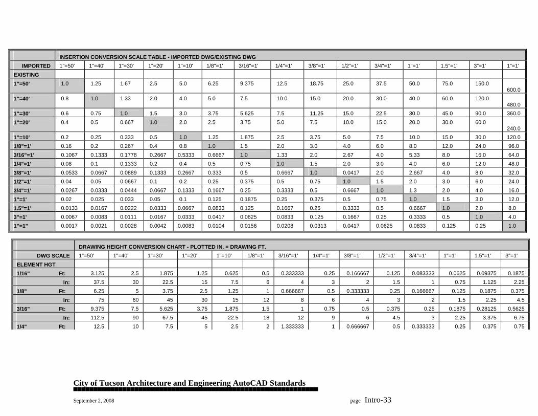
City of Tucson Architecture and Engineering AutoCAD Standards ▀▀▀▀▀▀▀▀▀▀▀▀▀▀▀▀▀▀▀▀▀▀▀▀▀▀▀▀▀▀▀▀▀▀▀▀▀▀▀▀▀▀▀▀▀▀▀▀▀▀▀▀▀▀▀▀▀▀▀▀ September 2, 2008 page Intro-33
INSERTION CONVERSION SCALE TABLE - IMPORTED DWG/EXISTING DWG
IMPORTED 1"=50'
1"=40'
1"=30'
1"=20'
1"=10'
1/8"=1'
3/16"=1'
1/4"=1'
3/8"=1'
1/2"=1'
3/4"=1'
1"=1'
1.5"=1'
3"=1'
1"=1'
EXISTING
1"=50'
1.0
1.25
1.67
2.5
5.0
6.25
9.375
12.5
18.75
25.0
37.5
50.0
75.0
150.0
600.0
1"=40' 0.8
1.0
1.33
2.0
4.0
5.0
7.5
10.0
15.0
20.0
30.0
40.0
60.0
120.0
480.0
1"=30' 0.6
0.75
1.0
1.5
3.0
3.75
5.625
7.5
11.25
15.0
22.5
30.0
45.0
90.0
360.0
1"=20' 0.4
0.5
0.667
1.0
2.0
2.5
3.75
5.0
7.5
10.0
15.0
20.0
30.0
60.0
240.0
1"=10' 0.2
0.25
0.333
0.5
1.0
1.25
1.875
2.5
3.75
5.0
7.5
10.0
15.0
30.0
120.0
1/8"=1' 0.16
0.2
0.267
0.4
0.8
1.0
1.5
2.0
3.0
4.0
6.0
8.0
12.0
24.0
96.0
3/16"=1' 0.1067
0.1333
0.1778
0.2667
0.5333
0.6667
1.0
1.33
2.0
2.67
4.0
5.33
8.0
16.0
64.0
1/4"=1' 0.08
0.1
0.1333
0.2
0.4
0.5
0.75
1.0
1.5
2.0
3.0
4.0
6.0
12.0
48.0
3/8"=1' 0.0533
0.0667
0.0889
0.1333
0.2667
0.333
0.5
0.6667
1.0
0.0417
2.0
2.667
4.0
8.0
32.0
1/2"=1' 0.04
0.05
0.0667
0.1
0.2
0.25
0.375
0.5
0.75
1.0
1.5
2.0
3.0
6.0
24.0
3/4"=1' 0.0267
0.0333
0.0444
0.0667
0.1333
0.1667
0.25
0.3333
0.5
0.6667
1.0
1.3
2.0
4.0
16.0
1"=1' 0.02
0.025
0.033
0.05
0.1
0.125
0.1875
0.25
0.375
0.5
0.75
1.0
1.5
3.0
12.0
1.5"=1' 0.0133
0.0167
0.0222
0.0333
0.0667
0.0833
0.125
0.1667
0.25
0.3333
0.5
0.6667
1.0
2.0
8.0
3"=1' 0.0067
0.0083
0.0111
0.0167
0.0333
0.0417
0.0625
0.0833
0.125
0.1667
0.25
0.3333
0.5
1.0
4.0
1"=1" 0.0017
0.0021
0.0028
0.0042
0.0083
0.0104
0.0156
0.0208
0.0313
0.0417
0.0625
0.0833
0.125
0.25
1.0
DRAWING HEIGHT CONVERSION CHART - PLOTTED IN. = DRAWING FT.
DWG SCALE 1"=50'
1"=40'
1"=30'
1"=20'
1"=10'
1/8"=1'
3/16"=1'
1/4"=1'
3/8"=1'
1/2"=1'
3/4"=1'
1"=1'
1.5"=1'
3"=1'
ELEMENT HGT
1/16" Ft:
3.125
2.5
1.875
1.25
0.625
0.5
0.333333
0.25
0.166667
0.125
0.083333
0.0625
0.09375
0.1875
In:
37.5
30
22.5
15
7.5
6
4
3
2
1.5
1
0.75
1.125
2.25 1/8" Ft:
6.25
5
3.75
2.5
1.25
1
0.666667
0.5
0.333333
0.25
0.166667
0.125
0.1875
0.375
In:
75
60
45
30
15
12
8
6
4
3
2
1.5
2.25
4.5 3/16" Ft:
9.375
7.5
5.625
3.75
1.875
1.5
1
0.75
0.5
0.375
0.25
0.1875
0.28125
0.5625
In:
112.5
90
67.5
45
22.5
18
12
9
6
4.5
3
2.25
3.375
6.75 1/4" Ft:
12.5
10
7.5
5
2.5
2
1.333333
1
0.666667
0.5
0.333333
0.25
0.375
0.75

City of Tucson Architecture and Engineering AutoCAD Standards ▀▀▀▀▀▀▀▀▀▀▀▀▀▀▀▀▀▀▀▀▀▀▀▀▀▀▀▀▀▀▀▀▀▀▀▀▀▀▀▀▀▀▀▀▀▀▀▀▀▀▀▀▀▀▀▀▀▀▀▀ September 2, 2008 page Intro-34
In:
150
120
90
60
30
24
16
12
8
6
4
3
4.5
9
3/8" Ft:
18.75
15
11.25
7.5
3.75
3
2
1.5
1
0.75
0.5
0.375
0.5625
1.125 In:
225
180
135
90
45
36
24
18
12
9
6
4.5
6.75
13.5
1/2" Ft:
25
20
15
10
5
4 2.666667
2
1.333333
1
0.666667
0.5
0.75
1.5
In:
300
240
180
120
60
48
32
24
16
12
8
6
9
18 3/4" Ft:
37.5
30
22.5
15
7.5
6
4
3
2
1.5
1
0.75
1.125
2.25
In:
450
360
270
180
90
72
48
36
24
18
12
9
13.5
27 1" Ft:
50
40
30
20
10
8
5.333333
4
2.666667
2
1.333333
1
1.5
3
In:
600
480
360
240
120
96
64
48
32
24
16
12
18
36
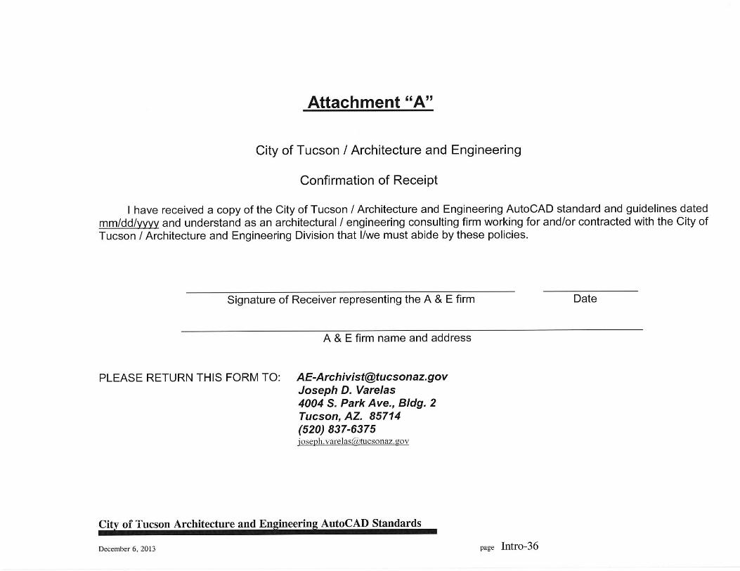
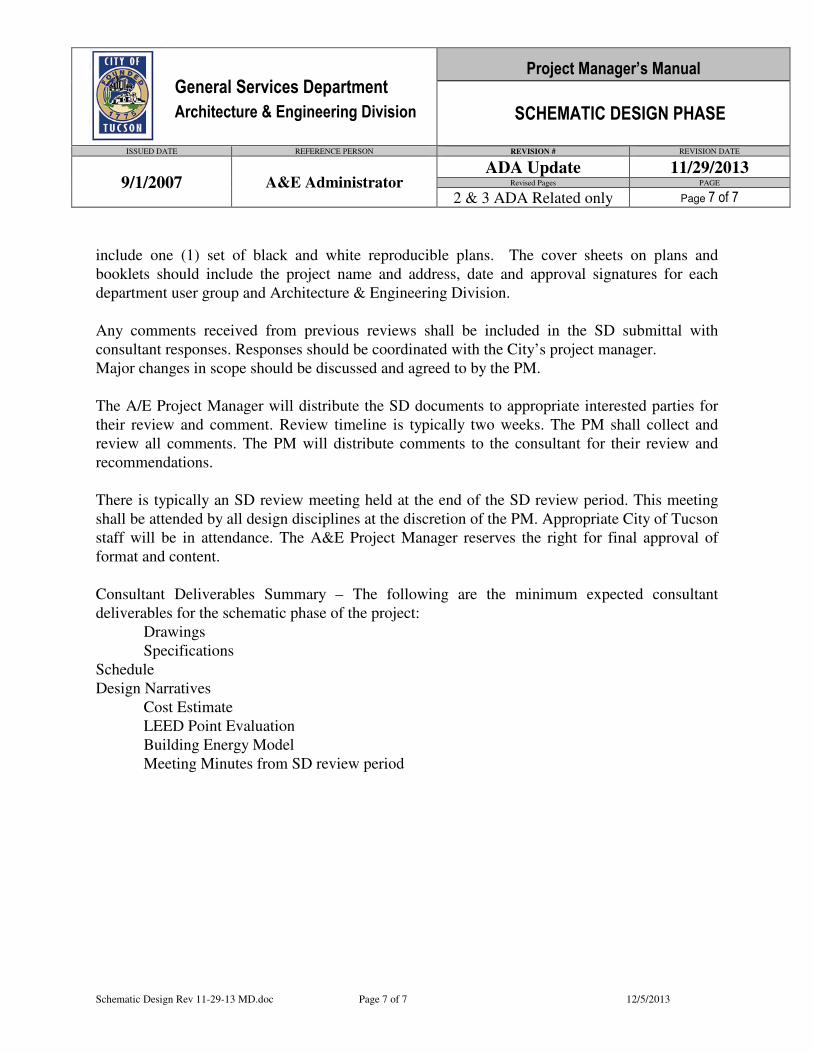
General Services Department
Architecture & Engineering Division
Project Manager’s Manual
SCHEMATIC DESIGN PHASE
ISSUED DATE REFERENCE PERSON REVISION # REVISION DATE
9/1/2007 A&E Administrator ADA Update 11/29/2013
Revised Pages PAGE
2 & 3 ADA Related only Page 7 of 7
Schematic Design Rev 11-29-13 MD.doc Page 7 of 7 12/5/2013
include one (1) set of black and white reproducible plans. The cover sheets on plans and
booklets should include the project name and address, date and approval signatures for each
department user group and Architecture & Engineering Division.
Any comments received from previous reviews shall be included in the SD submittal with
consultant responses. Responses should be coordinated with the City’s project manager.
Major changes in scope should be discussed and agreed to by the PM.
The A/E Project Manager will distribute the SD documents to appropriate interested parties for
their review and comment. Review timeline is typically two weeks. The PM shall collect and
review all comments. The PM will distribute comments to the consultant for their review and
recommendations.
There is typically an SD review meeting held at the end of the SD review period. This meeting
shall be attended by all design disciplines at the discretion of the PM. Appropriate City of Tucson
staff will be in attendance. The A&E Project Manager reserves the right for final approval of
format and content.
Consultant Deliverables Summary – The following are the minimum expected consultant
deliverables for the schematic phase of the project:
Drawings
Specifications
Schedule
Design Narratives
Cost Estimate
LEED Point Evaluation
Building Energy Model
Meeting Minutes from SD review period
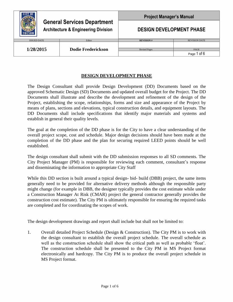
Page 1 of 6
DESIGN DEVELOPMENT PHASE
The Design Consultant shall provide Design Development (DD) Documents based on the
approved Schematic Design (SD) Documents and updated overall budget for the Project. The DD
Documents shall illustrate and describe the development and refinement of the design of the
Project, establishing the scope, relationships, forms and size and appearance of the Project by
means of plans, sections and elevations, typical construction details, and equipment layouts. The
DD Documents shall include specifications that identify major materials and systems and
establish in general their quality levels.
The goal at the completion of the DD phase is for the City to have a clear understanding of the
overall project scope, cost and schedule. Major design decisions should have been made at the
completion of the DD phase and the plan for securing required LEED points should be well
established.
The design consultant shall submit with the DD submission responses to all SD comments. The
City Project Manager (PM) is responsible for reviewing each comment, consultant’s response
and disseminating the information to appropriate City Staff
While this DD section is built around a typical design- bid- build (DBB) project, the same items
generally need to be provided for alternative delivery methods although the responsible party
might change (for example in DBB, the designer typically provides the cost estimate while under
a Construction Manager At Risk (CMAR) project the general contractor generally provides the
construction cost estimate). The City PM is ultimately responsible for ensuring the required tasks
are completed and for coordinating the scopes of work.
The design development drawings and report shall include but shall not be limited to:
1. Overall detailed Project Schedule (Design & Construction). The City PM is to work with
the design consultant to establish the overall project schedule. The overall schedule as
well as the construction schedule shall show the critical path as well as probable ‘float’.
The construction schedule shall be presented to the City PM in MS Project format
electronically and hardcopy. The City PM is to produce the overall project schedule in
MS Project format.
General Services Department
Architecture & Engineering Division
Project Manager’s Manual
DESIGN DEVELOPMENT PHASE
ISSUED DATE Editor REVISION # REVISION DATE
1/28/2015 Dodie Frederickson
Revised Pages PAGE
Page 1 of 6

Page 2 of 6
2. Construction cost estimate with detailed breakdown by major construction disciplines (+/-
10% accuracy). If the scope is over budget the design team should define and document
add alternates that can be prioritized and added to the scope depending on available
budget. Construction Manager shall provide the construction cost estimate for CMAR
projects. If requested, the design consultant is also expected to provide a cost estimate by
major discipline for comparison to the CMAR’s estimate. Consultant is to provide a
comprehensive cost estimate and work with the City PM to establish the overall project
budget
3. Provide HVAC, lighting and electric load calculations, and develop estimates for the cost
of operating and maintaining the facilities designed under this Contract. Assumptions
shall be clearly noted. The estimated operation and maintenance costs are to be projected
for each of the thirty (30) consecutive fiscal years following acceptance of the facilities by
the City. Each system shall be evaluated for operating cost. The evaluation will take into
consideration replacement. All economic cost evaluations shall be taken as simple
payback with the yearly owning cost averaged over the period. The ASHRAE HVAC
Applications Handbook 2011 shall be used as a reference and chapter 35 in particular for
service life estimates. All calculations shall be submitted and will become the property of
The City. The following operating cost estimates are to be provided:
a. Estimate of annual utility costs for gas, electrical, water, and sewer.
b. Estimate of annual maintenance costs.*
c. Suggested additive or deductive alternatives with estimated costs.*
* (City Project Manager is to provide copies to the Maintenance
Superintendents and Energy Manager.)
3. Site Plan
a. Site description.
b. Scope of work.
c. Conceptual grading plan.
d. List references to all pertinent codes and regulations.
e. List design assumptions.
f. Conceptual design of paving, sidewalks, curbs, fences, gates, parking, roads, and
other site improvements showing conceptual horizontal and vertical control data.
g. Drainage, detention / retention ponds and water harvesting concept, refer to: http://dot.ci.tucson.az.us/stormwater/downloads/2006WaterHarvesting.pdf .
Include the latest revision stating that rainwater harvesting systems capture 100%
of the rooftop rainfall over a 72 hr period.
h. Utility design plans for gas, water, electrical, telephone, sewer, TV cable, Fiber
Optic, Microwave, Wireless and other data properly identified and labeled
(private, public ...).
i. Communications UG conduits, conduit size and location with 2500# traceable
muletape, innerduct, maxcell, tracer wire. Include trench details with traceable foil
I.D. tape that lays in the trench 18” above the conduit.
Page 3 of 6
j. Ensure there is to be no gravel in mechanical yards, use asphalt or concrete
paving.
k. Accessibility ADA: Identify accessible route beginning from point of public
transportation, including parking, sidewalks, curb ramps, site ramps, stairs, and
provide slope information for all.
4. Landscape Plan (City Project Manager to review with City Urban Landscaping Planner
for conformance with Xeroscape requirements.)
a. Identified Vegetation
b. Conceptual Landscape Plan
c. Conceptual Irrigation Plan
d. Drainage and water retention concept.
e.
5. Code Analysis with preliminary approval by Development Services and other authority
having jurisdictions. Provide a list of all the necessary permits with probable costs and
estimated time durations for securing these permits.
6. Foundation Plans
a. Foundation system definition with conceptual foundation layout and sections.
b. Slabs on grade showing estimated thicknesses and other pertinent details needed
for the final design.
7. Structural framing Plans
a. Roof structure with typical sections and details
b. Structural framing system, plans, sections, elevations and details.
c. Structural roof masts and independent towers for communications.
8. Exterior wall elevations, and sections defining all materials, supports, bracing, ties,
reinforcing etc.
9. Typical interior bearing or firewalls sections defining thickness, supporting concept, etc.
10. Typical architectural roofing and flashing details
11. Floor plans, all levels and roofs
a. Partition type identifications.
b. Smoke and fire compartmentalization.
c. Built-ins and fixed equipment shown and noted.
d. 1/4” scale furniture and movable equipment layouts, for ALL spaces.
e. Accessibility (ADA): Depict required floor clearances and maneuvering space at
all elements required to be accessible, i.e. plumbing fixtures, doors, counters, etc.
12. Reflected Ceiling Plan
a. Lights, diffusers, grilles, sprinkler heads and unusual conditions.
Page 4 of 6
13. Room finish, door schedules, and a narrative of the door hardware functions for all
areas/spaces, include wall texture, surfacing material, and paint types and color.
14. Fixed equipment schedule, locations, and service requirements.
15. Plumbing Systems
a. Fixture schedule, locations.
b. Equipment schedule, locations.
c. Water piping, locations (sizes for pipes larger than 1”).
d. Waste piping, locations (sizes for pipes larger than 4”).
e. Catalog sheets of exposed fixtures.
f. Water pressure data and calculations.
g Show maintenance access to vital pieces of plumbing equipment.
16. Roof drainage system, locations, and key sizes
17. Fire Protection Systems
a. Provide system performance design criteria.
b. Fire Riser location.
18. Mechanical Systems
a. Equipment schedule, locations, sizes, types, load information.
b. Equipment filter sizes and quantities with adequate maintenance clearances.
c. Supply, return, and exhaust duct layout.
d. Catalog sheets of exposed fixtures.
e. Control concepts and sequence of operation for major equipment.
f. Reestablish life cycle analysis of energy saving equipment and options from the
Schematic Phase.
g. Provide separate storage room for 1 year supply of filters (shall also include space
for 1 year supply of lamps & fuses for electrical. Provide for “attic stock” ceiling
tile storage on site).
h. Show maintenance access to vital pieces of mechanical equipment.
19. HVAC piping, locations, and sizes for pipes larger than 1”
20. Power Distribution
a. Panel locations and schedules.
b. Terminal distribution to equipment and receptacles.
c. Motor control schedules.
d. One Line diagram.
e. Load calculations.
f. Fault calculations.
Page 5 of 6
21. Lighting
a. Final fixture and switch locations and branch circuits.
b. Catalog sheets.
c. power density calculations for each space
d. lighting fixture schedule
22. Communication and alarm systems description and floor area space requirements
a. Identification and scope.
b. Data and phone drops located.
c. Communications equipment room(s) sized and located on floor plans.
d. Communication room wall elevations and rack locations. Include ladder-ways,
electrical layout on the racks, and fire retardant A/C ¾” plywood location.
e. Show grounding buss on everything with a one line diagram from the main
electrical equipment. .
f. Number all tele/data information outlets.
g. Show conduits, size and location.
h. Redundant cooling
i. Emergency lighting
23 Special systems
a. Final layout and specification.
b. Catalog sheets.
c. Where large meeting rooms, classrooms, and auditoriums are part of the project,
DD is when ceiling heights and design is established with an Acoustic Engineer.
AV control location are located and AV layout is established with an AV
specialist.
24 Description of proposed additive alternates and cost estimates for each
25 Materials and color boards
26 Specifications
a. Table of contents for technical sections.
b. All sections project specific.
c. Written descriptions of all options, allowances, unit prices, and special
construction scheduling requirements.
d. Provide checklist of all close out requirements to be followed at close out of
project to be updated at 100% CD’s
e. Provide checklist of excess products and quantities to be handed over to City such
as ceiling tiles, carpet, flooring and wall tiles and to be updated at 100% CD
27 Third Party Commissioning Agent (CA) – The City PM is responsible for ensuring the
commissioning agent has been contracted and has reviewed the project basis of design
and design documents. The design consultant is required to include the Construction
Page 6 of 6
Administrator’s review of the basis of design, SD comments, preliminary commissioning
plan and preliminary commissioning specifications in the DD report. The CA will review
and comment to the design consultant on the DD phase report. All systems to be
commissioned will be identified and noted by the design consultant. Commissioning is to
be performed to meet the requirements for the U.S.G.B.C. LEED enhanced
commissioning credit.
28. LEED and the Sustainable Energy Standard – update required information from SD phase
as needed including 5% for solar offset and solar readiness. Working with the City PM
the design consultant shall provide an estimate for achieving LEED. The estimated cost
for LEED would include those items necessary for achieving LEED Silver over a baseline
of a 2005 City standard building.
29. All of the above information is to be reproduced in black and white and ten (10) copies
(unless otherwise noted in the contract) distributed to the City of Tucson Architecture &
Engineering Office, which will in turn distribute copies to each of the user departments
and agencies. The cover sheets on plans and booklets should include the project name
and address, phase, list of alternates, date and approval signatures from each department
user group and Architecture & Engineering. Option: provide electronic submission of the
above for DD review documents.
30. Written Documentation - All written documentation shall be submitted in electronic files
in Microsoft Office format.
A&E reserves the right for final approval of format and content.
MASTPLAN.DOC Page 1 of 2 6/24/2008
Project Manager’s Manual General Services Department Architecture & Engineering Division ARCHITECTURAL MASTER PLAN PHASE
ISSUED DATE REFERENCE PERSON REVISION # REVISION DATE
1 6/18/2008 Revised Pages PAGE 9/1/2007 M. Reece
1 Page 1 of 1 The Consultant is to prepare the following documentation for this phase of the work to include but not be limited to: A. Facts: Facts are documented to describe present aspects of the proposed site.
They are intended to answer the question: What is known about the site? Facts should include but not be limited to:
• Site survey • Site size • Adjacent uses • Slope and grades • Vehicular Access • Pedestrian Access • Sun Path • Water, sewer and gas lines • Power, telephone, cable and data lines • Zoning Analysis • Archeological Report • Hydrology Report • Geotechnical Investigation • Environmental Analysis and Report • Traffic Access Analysis • On - site Traffic Analysis • Vegetation • Public Transportation
B. Needs: To be based upon the previously approved Architectural Design Program. C. Concepts: To be based upon a combination of the Facts, Needs and Budget. Develop several key alternatives for review and approval by the planning committee. Special considerations, as applicable:
• Components by size, type and description; • Alternative approaches to project resolution;
General Services Department
Architecture & Engineering Division
Project Manager’s Manual
CONSTRUCTION DOCUMENT PHASE
ISSUED DATE REFERENCE PERSON REVISION # REVISION DATE
9/1/2007 Administration 3 11/29/2013
Revised Pages PAGE
1 & 3 ADA Related only Page 1 of 1
Consdoc Rev 11-29-13.doc Page 1 of 4 12/5/2013
CONSTRUCTION DOCUMENTS PHASE
The Architect shall provide Construction Documents based on the approved Design
Development Documents and updated budget for the Cost of the Work. The Construction
Documents shall set forth in detail the requirements for construction of the Project. The
Construction Documents shall include Drawings and Specifications that establish in detail the
quality levels of materials and systems required for the Project. The Architect shall assist A&E in
establishing a list of prospective bidders or contractors. The Architect shall assist A&E in bid
validation or proposal evaluation and determination of the successful bid or proposal, if any. The
Construction Documents shall include but shall not be limited to:
1. Project Schedule
2. Construction cost estimate with area breakdowns (net and gross) and analysis.
a. List and description of proposed Additive alternates.
b. Reaffirm annual utility costs for gas, electrical, water, and sewer.
c. Reaffirm annual maintenance costs.
3. Site Plan
a. Detailed design of paving, sidewalks, curbs, fences, parking, roads, and other site
improvements showing conceptual horizontal and vertical control data needed for
construction.
b. Drainage, detention / retention ponds and all necessary details for water
harvesting.
c. Utility design plans for gas, water, electrical, telephone, sewer, TV cable and
other data properly identified. Sections shall clarify congested areas.
d. Detailed Landscape design plans.
e. Cut - fill estimated quantities with specified shrink factor.
f. No gravel in mechanical yards, use asphalt or concrete paving.
e. Accessibility (ADA): Provide detailed information for parking, layout(s), signage,
sidewalks, curb ramps, site ramps, stairs, and railings.
4. Foundation Plans
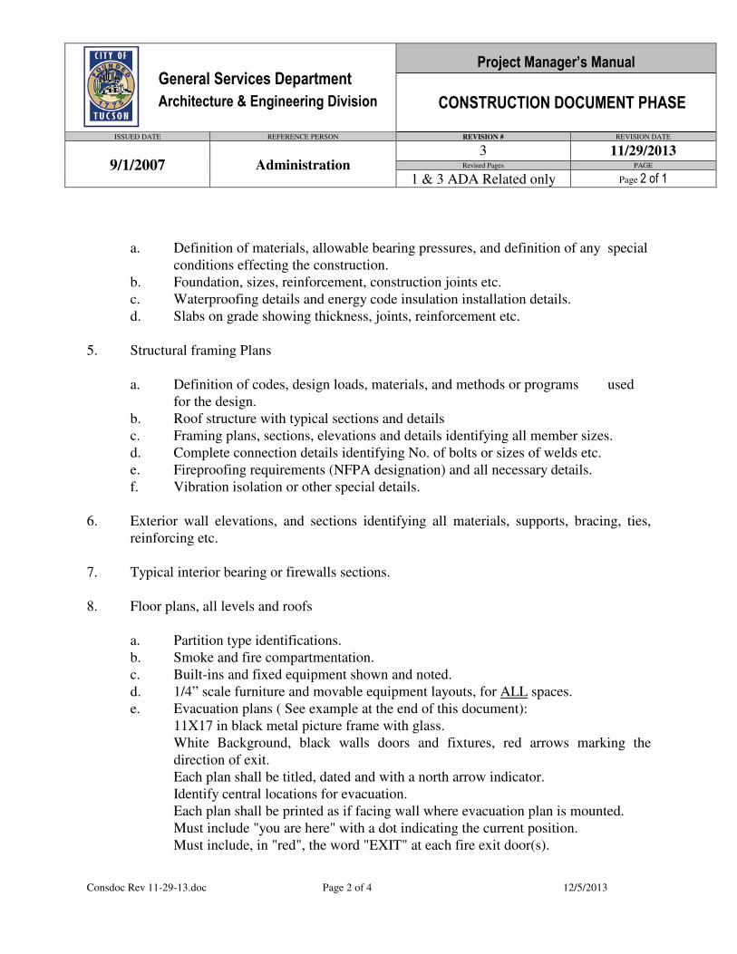
General Services Department
Architecture & Engineering Division
Project Manager’s Manual
CONSTRUCTION DOCUMENT PHASE
ISSUED DATE REFERENCE PERSON REVISION # REVISION DATE
9/1/2007 Administration 3 11/29/2013
Revised Pages PAGE
1 & 3 ADA Related only Page 2 of 1
Consdoc Rev 11-29-13.doc Page 2 of 4 12/5/2013
a. Definition of materials, allowable bearing pressures, and definition of any special
conditions effecting the construction.
b. Foundation, sizes, reinforcement, construction joints etc.
c. Waterproofing details and energy code insulation installation details.
d. Slabs on grade showing thickness, joints, reinforcement etc.
5. Structural framing Plans
a. Definition of codes, design loads, materials, and methods or programs used
for the design.
b. Roof structure with typical sections and details
c. Framing plans, sections, elevations and details identifying all member sizes.
d. Complete connection details identifying No. of bolts or sizes of welds etc.
e. Fireproofing requirements (NFPA designation) and all necessary details.
f. Vibration isolation or other special details.
6. Exterior wall elevations, and sections identifying all materials, supports, bracing, ties,
reinforcing etc.
7. Typical interior bearing or firewalls sections.
8. Floor plans, all levels and roofs
a. Partition type identifications.
b. Smoke and fire compartmentation.
c. Built-ins and fixed equipment shown and noted.
d. 1/4” scale furniture and movable equipment layouts, for ALL spaces.
e. Evacuation plans ( See example at the end of this document):
11X17 in black metal picture frame with glass.
White Background, black walls doors and fixtures, red arrows marking the
direction of exit.
Each plan shall be titled, dated and with a north arrow indicator.
Identify central locations for evacuation.
Each plan shall be printed as if facing wall where evacuation plan is mounted.
Must include "you are here" with a dot indicating the current position.
Must include, in "red", the word "EXIT" at each fire exit door(s).
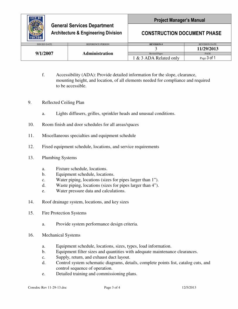
General Services Department
Architecture & Engineering Division
Project Manager’s Manual
CONSTRUCTION DOCUMENT PHASE
ISSUED DATE REFERENCE PERSON REVISION # REVISION DATE
9/1/2007 Administration 3 11/29/2013
Revised Pages PAGE
1 & 3 ADA Related only Page 3 of 1
Consdoc Rev 11-29-13.doc Page 3 of 4 12/5/2013
f. Accessibility (ADA): Provide detailed information for the slope, clearance,
mounting height, and location, of all elements needed for compliance and required
to be accessible.
9. Reflected Ceiling Plan
a. Lights diffusers, grilles, sprinkler heads and unusual conditions.
10. Room finish and door schedules for all areas/spaces
11. Miscellaneous specialties and equipment schedule
12. Fixed equipment schedule, locations, and service requirements
13. Plumbing Systems
a. Fixture schedule, locations.
b. Equipment schedule, locations.
c. Water piping, locations (sizes for pipes larger than 1”).
d. Waste piping, locations (sizes for pipes larger than 4”).
e. Water pressure data and calculations.
14. Roof drainage system, locations, and key sizes
15. Fire Protection Systems
a. Provide system performance design criteria.
16. Mechanical Systems
a. Equipment schedule, locations, sizes, types, load information.
b. Equipment filter sizes and quantities with adequate maintenance clearances.
c. Supply, return, and exhaust duct layout.
d. Control system schematic diagrams, details, complete points list, catalog cuts, and
control sequence of operation.
e. Detailed training and commissioning plans.
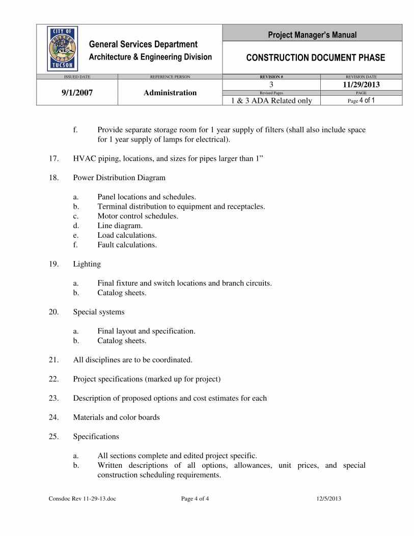
General Services Department
Architecture & Engineering Division
Project Manager’s Manual
CONSTRUCTION DOCUMENT PHASE
ISSUED DATE REFERENCE PERSON REVISION # REVISION DATE
9/1/2007 Administration 3 11/29/2013
Revised Pages PAGE
1 & 3 ADA Related only Page 4 of 1
Consdoc Rev 11-29-13.doc Page 4 of 4 12/5/2013
f. Provide separate storage room for 1 year supply of filters (shall also include space
for 1 year supply of lamps for electrical).
17. HVAC piping, locations, and sizes for pipes larger than 1”
18. Power Distribution Diagram
a. Panel locations and schedules.
b. Terminal distribution to equipment and receptacles.
c. Motor control schedules.
d. Line diagram.
e. Load calculations.
f. Fault calculations.
19. Lighting
a. Final fixture and switch locations and branch circuits.
b. Catalog sheets.
20. Special systems
a. Final layout and specification.
b. Catalog sheets.
21. All disciplines are to be coordinated.
22. Project specifications (marked up for project)
23. Description of proposed options and cost estimates for each
24. Materials and color boards
25. Specifications
a. All sections complete and edited project specific.
b. Written descriptions of all options, allowances, unit prices, and special
construction scheduling requirements.
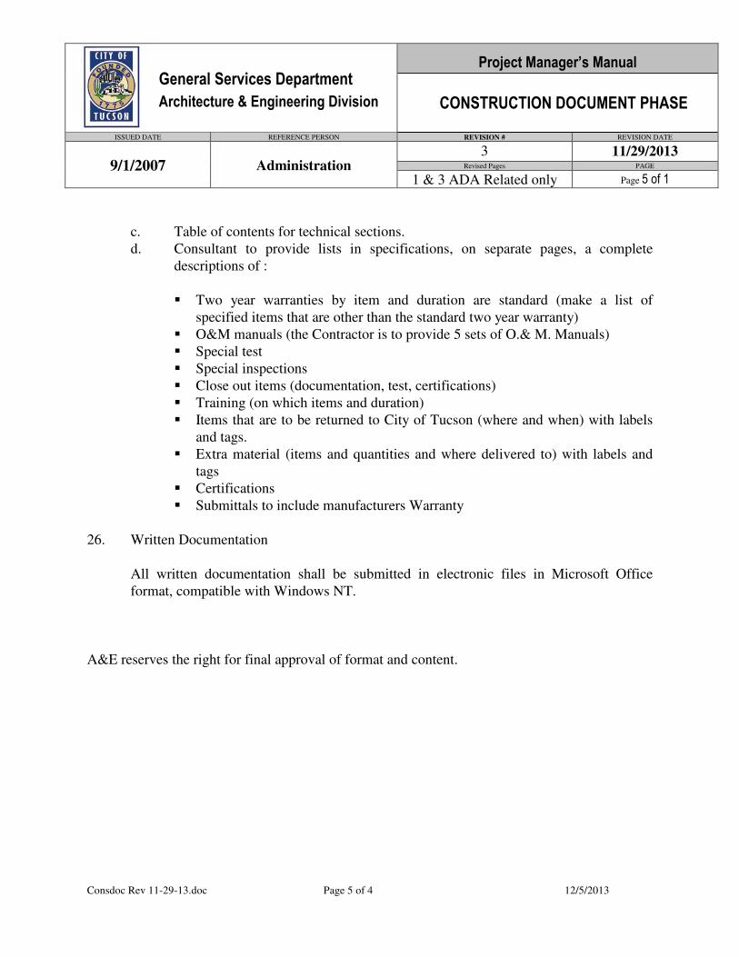
General Services Department
Architecture & Engineering Division
Project Manager’s Manual
CONSTRUCTION DOCUMENT PHASE
ISSUED DATE REFERENCE PERSON REVISION # REVISION DATE
9/1/2007 Administration 3 11/29/2013
Revised Pages PAGE
1 & 3 ADA Related only Page 5 of 1
Consdoc Rev 11-29-13.doc Page 5 of 4 12/5/2013
c. Table of contents for technical sections.
d. Consultant to provide lists in specifications, on separate pages, a complete
descriptions of :
� Two year warranties by item and duration are standard (make a list of
specified items that are other than the standard two year warranty)
� O&M manuals (the Contractor is to provide 5 sets of O.& M. Manuals)
� Special test
� Special inspections
� Close out items (documentation, test, certifications)
� Training (on which items and duration)
� Items that are to be returned to City of Tucson (where and when) with labels
and tags.
� Extra material (items and quantities and where delivered to) with labels and
tags
� Certifications
� Submittals to include manufacturers Warranty
26. Written Documentation
All written documentation shall be submitted in electronic files in Microsoft Office
format, compatible with Windows NT.
A&E reserves the right for final approval of format and content.

WKSPSTD Rev 11-29-13 MD.doc Page 1 of 15 12/5/2013
WORKSPACE STANDARDS
The Workspace Standards which follow are intended for programming, design and layout
of workspaces commonly associated with administrative, clerical, managerial, technical,
data entry and design personnel. Non standard spaces such as conference rooms,
classrooms, storage, reception, and technical rooms should follow professional standards of
practice. Refer to A&E Design Standards for further requirements during each phase of
work.
As a point of reference, this information has been adapted from the April 1990, State of
Arizona, Department of Administration Building System Space and Building Development
Standards to fit the criteria of the City of Tucson, Division of Architecture & Engineering.
GOALS
Equity in the quality of workspace for each level of employee throughout the City of Tucson.
Ergonomic performance for all design configurations. Especially important is the selection
of task chairs, computer set-up, keyboard adjustment, reach distances for transaction counters
and worksurface.
Modularity of layout based upon type of workspace.
Uniformity and interchangeability of system components.
Planned flexibility for future layout changes.
Accessibility (ADA): City facilities, as public buildings, shall be designed and constructed
for accessibility and use by the disabled. Refer to Division 01, General Conditions, ADA
Section 013500 of the Architecture and Engineering design and construction standards.
MODULARITY
The space standards assume that the workspaces will follow a basic symmetrical grid. In new
construction, a planning grid should be established that matches the building structural grid to the
workspace grid. In existing construction the designer should work to establish a symmetrical
grid to the maximum extent possible within the confines of the existing structure.
The guidelines are the same for both shared open areas and private offices. Private offices are to
be configured with the same modular dimensions, computer setup and worksurfaces as the open
General Services Department
Architecture & Engineering Division
Project Manager’s Manual
PROJECT MANAGER’S OVERVIEW
ISSUED DATE REFERENCE PERSON REVISION # REVISION DATE
9/1/2007 Administrator 2 11/29/2013
Revised Pages PAGE
1,3,6,8,9,10,11,13 Page 1 of 1
WKSPSTD Rev 11-29-13 MD.doc Page 2 of 15 12/5/2013
spaces. The permanent walls are to be located to match the modular dimensions of the open
areas. For future flexibility all components are to be interchangeable.
BUILDING GRID
With new building design, the entire departmental work area should be laid out on a standard
workspace grid such as 4’x4’, 6’, 8’ x 8’ or 10’, etc. Conference rooms, private offices, storage
rooms and other enclosed spaces should be laid out to match this grid. Future addition or
removal of permanent walls can then be accommodated with this grid.
MATERIALS
All panels, worksurfaces and storage components are to be finished with standard manufacturer
materials. Custom finishes, fabrics and upholstery are not acceptable unless with the written
approval of A&E.
AREA
The areas listed herein represent net useable square feet, unless noted otherwise, for each specific
room type and do not include the required additional factors for departmental circulation and
layout. Departmental layout area must be multiplied the net-to-gross square footage conversion
factor that account for major fire corridors, vertical circulation, toilets, walls and engineering
systems. The circulation and layout factor is added to the sum of the interior spaces itemized by
department and division. For this application the factor varies between 15% and 21% depending
upon the proportionate magnitude of the planned space. The appropriate factors for each
component are displayed on the space requirements database forms.
APPLICATION
The material which follows explains the methodology for calculating and applying the standards
to the needs of the occupants of the building or part thereof. Drawings of suggested office,
workstation, conference room and reception layouts and form many types of furniture and
equipment are provided at the end of this section.
PRIVATE OFFICES
Private offices are reserved for Department Heads, Assistant Department Heads and Division
Administrators. Private offices for personnel below this level shall only be approved with
written authorization by A&E. The assignment of private offices for other personnel shall only
be considered when the job description requires an unusually high degree of privacy. In these
areas, it has been assumed that the furniture is functionally appropriate and arranged for the
convenience of the person using it. Private offices are enclosed by fullheight partition walls or
partitions and are suitable for individuals requiring some degree of acoustical privacy.
WKSPSTD Rev 11-29-13 MD.doc Page 3 of 15 12/5/2013
Accessibility (ADA): City facilities, as public buildings, shall be designed and constructed for
accessibility and use by the disabled. Refer to Division 01, General Conditions, ADA Section
013500 of the Architecture and Engineering design and construction standards.
OPEN or PARTITION WORKSTATIONS
In general office area, the duties inherent in the position determine the type of workstation
assigned. Work station which may be used by personnel in open areas include desks, chairs, side
chairs, credenzas, and computers. The net square footage required for each station is determined
by adding the physical area of the work surface to the working space required by the person using
the station. The space is then increased by one-half of the aisleway necessary to approach the
workstation.
Although the height of workstation partitions will be determined by the space planner and the
client, it is suggested that at least two or three partition heights be considered when the system
manufacturer is selected. This will permit the interior planners and designers to exercise some
discretion in assigning workstation partition heights and provide them flexibility to address the
needs for privacy, storage and supervision of employees.
Every workstation shall be considered to have a computer unless noted otherwise.
CONFERENCE AND MEETING ROOMS
Enclosed conference rooms to seat 10 to 12 people should be provided for every 20 people. In
addition, open breakout area to seat 4 to 6 should be provided for every 12 people. The size of
spaces should be based on good professional standards. Special consideration should be given to
requirements for Communication and Audio Visual. Smart screens may be appropriate for some
rooms.
Install assistive listening devises for any new city meeting room with an occupant load of more
than 50 or where an audio amplification system is installed. We should provide a minimum of 3
receivers. If the occupant load is 100 or more provide 5 receivers or 4% of the total seating,
whichever is greater. Signage complying with 1106.16.2 of the UBC shall also be installed
notifying citizens of the availability of the listening system.
Accessibility (ADA): City facilities, as public buildings, shall be designed and constructed for
accessibility and use by the disabled. Refer to Division 01, General Conditions, ADA Section
013500 of the Architecture and Engineering design and construction standards.
TECHNOLOGY
Architecture & Engineering wishes to implement buildings incorporating the latest in planning
and technology systems. This applies to furnishings, communication equipment (computers,
telephone, fax, cad, etc.), energy management systems, engineering and architecture. Design of
WKSPSTD Rev 11-29-13 MD.doc Page 4 of 15 12/5/2013
the core and shell is critical in achieving future planning flexibility, efficient operating costs,
good space utilization, serviceability, ease of maintenance, security, comfort and image.
SITE ORIENTATION
Buildings shall be oriented to maximize potential views from within the site and towards the
surrounding environs. Orient the structure to maximize the positive climate characteristics of the
site and minimize adverse environmental impacts. The building envelope shall be designed to
utilize passive solar design where applicable. (i.e. low E glazing shade south exposure, etc). The
positive benefits of Arizona’s abundant sunlight for natural daylighting of interior spaces.
Building Design Criteria
Building Configuration Requirements: Provide appropriate bay sizes, bay depths, distance from
natural light, access to services so that the following definitions and requirements can be met.
Floor Sizes: Minimum floor sizes of 25,000 NSF for typical office and administrative, buildings.
Other special floor size considerations might include:
Usable Space Depth: The structure shall be designed so that the depth of space
from the exterior wall to the interior corridor wall (or other permanent wall) shall
not be less than a nominal 30’-0” or more than a nominal 45’-0” unless there is an
interior atrium or light well no greater than 45’-0” from any occupied space.
Proportion: Provide overall average building daylighting ratio (NSF of Occupied
workspace, not including conference, storage and other support areas, divided by lineal
feet of perimeter glass surface, not deducting for intervening perimeter columns less
than 36” wide) of less than 60 (this is an expression of the average maximum depth of
space from natural light). Buildings with a slenderness ratio of lower than 40 (NSF per
lineal foot of glass) may be too narrow and not provide sufficient interior space to
allow development of tenant support and special areas.
Distance From Natural Light: In all above grade space other than training and conference areas,
that is considered NSF, no less than 90% of all space shall be within a distance of not more than
45 feet from natural light. This 45 feet is to be measured by occupant's line of site from their
workspace to the light source. The natural light may be provided by:
Perimeter Perimeter glazing with unobstructed interior open space, not obstructed by
full height partitioning nor full height glazing.
Atrium Glazing into an atrium area
Skylight By proximity to a skylight if on the top level of a building,

MASTPLAN.DOC Page 2 of 2 6/24/2008
• Impact on surrounding neighborhood--architectural compatibility, traffic patterns, noise and light levels, visual impact;
• Site evaluation--existing site, traffic/parking; zoning/legal restrictions, future site enhancements; agricultural assessment;
• Hazardous material evaluation; • ADA requirements; • Environmental impact (including Greenhouse Gas Emissions Estimates); • Energy conservation (should include specific concepts which must be
analyzed on a life-cycle cost basis); D. Construction phasing. E. Phasing of the entire project with appropriate scope and budget for each phase. F. Recommended Priority for Phasing and Master Plan Concept. G. Cost Summary. A&E reserves the right for final approval of format and content.
WKSPSTD Rev 11-29-13 MD.doc Page 5 of 15 12/5/2013
Distance to Services: No workstation or NSF will be enclosed private office and special area
spaces bounded by partitions on all sides. These full height partitions generally will be located
adjacent to or as extensions to core elements. In no instance should these full height spaces be
placed directly adjacent to an atria space and only in the instance of some larger private offices
should they be placed on the perimeter of a building. The placement of this full height space
should not obstruct access to natural light from atriums or the perimeter. The building footprint
and form should demonstrate how an average of 10% of the NSF can be placed in a location that
does not create a corridor situation (for fire exiting purposes), nor does it obstruct access to
natural light while at the same time not violating the above rules and performance criteria
regarding distance from workstations to natural light.
Floor to Floor Height: Floor to Ceiling Clearance: The building’s structure shall be designed so
that the minimum ceiling height from finished floor to finished ceiling is 9’-0” on all office
floors. Ceiling height shall be uniform throughout assignable space on each floor and shall be
uniform on all floors above grade.
The base building installation of mechanical duct loops, sprinkler lines, bulk heads and any other
items installed in the ceiling plenum spaces shall allow sufficient clearance for the tenant’s
ceiling-lighting system while maintaining the specified clear ceiling height throughout a
minimum of 97% of all NSF. This allows 3% to be obstructed to lower the height to 8’-6” clear
and/or to not allow a light fixture in that location, to accommodate transfer beams and
mechanical ducts. Provide a minimum of 8-inches clear under all piping, ducts, conduits and
structure so that all light fixtures can be relocated without obstructions. Utility lines installed
above ceiling to be held as close as possible to upper level floor or roof structure.
Bay Size: The general interior space planning concept requires open bays without interior
bearing walls within 45 feet of the perimeter building enclosure. Interior bearing walls shall be
allowed only at core locations where the surround core elements (stair, elevator, mechanical and
electrical shaft walls) or large tenant rooms.
Building Module: The open bay plan shall allow for the layout of office landscape type
workstations and enclosed office/conference rooms on a repetitive module. Perimeter column
spacing may range from 20’-0” minimum to 30’-0”. Column spacing at the perimeter closer than
20’ center to center shall not be allowed. Column and window mullion spacing shall
accommodate office widths of 8’, 12’, 16’ and 20’. Office and enclosed spaces located at the
perimeter must be developed without requiring “jogs” in the wall to align with window mullions
or column faces.
Maximum Height: The maximum height of the building shall be as allowed by the Tucson Land
Use Code. All levels of the building shall be served by freight and centralized passenger
elevators. At the main entrance there shall be a high bay space providing a centralized entrance
with a two story volume, space allowing visual identification of lobbies, waiting areas, counters
and major sub-division entrances at both the first and the second levels.
WKSPSTD Rev 11-29-13 MD.doc Page 6 of 15 12/5/2013
Exposed Roofs: Considering that a building may have a large footprint and be low-rise, it is
likely that different levels of the building may be of different floor sizes. This creates the
possibility of some lower level roofs being exposed from office space on upper levels. Extensive
exposed roof areas are to be avoided. A combination of vertical visual barriers and window
bulkhead heights on upper floors to obstruct the vision of undeveloped roof levels from a
location that is 20 feet from the perimeter as observed by a person 6 feet tall should be used to
prevent vision of an exposed roof. The line of vision of a person 6 feet tall standing 20 feet
inside of the perimeter bulk head must not observe unfinished roof area above the bulkhead or
below a 9’-0” ceiling height. Landscaping on terraces may NOT be employed to obscure the
view.
Vertical Flow: A centralized ceremonial stairway or open stair is encouraged to interconnect the
first two levels of the building. All stairways will be used for interfloor movement of personnel
and thus must be appropriately designed to promote their use.
Central Areas: At a minimum, a central building support area must be provided which
surrounds the central/vertical movement element, lobby, freight decks, and central services.
Within this area shall be located high volume and public oriented spaces including counters,
waiting areas, information delivery areas, public information displays, training rooms, auditorium
and centralized location of conference rooms. Centralized employee services, coffee stations and
break areas, lounges, mail delivery stations and on-floor service centers will be located in this
area.
Accessibility (ADA): City facilities, as public buildings, shall be designed and constructed for
accessibility and use by the disabled. Refer to Division 01, General Conditions, ADA Section
013500 of the Architecture and Engineering design and construction standards.
Public Facilities: Adjacent to the elevators on all public levels in the building, there shall be
public restrooms. All public restrooms shall be designed in accordance with all building codes
and ADA requirements, however, the minimum size of public restrooms to be provided are:
Men’s Room: The public men’s room shall provide two water closets, two urinals
and three lavatories.
Women’s Room: The women’s restroom shall provide three water closets and three
lavatories.
Accessibility (ADA): City facilities, as public buildings, shall be designed and constructed for
accessibility and use by the disabled. Refer to Division 01, General Conditions, ADA Section
013500 of the Architecture and Engineering design and construction standards.
Live loads: The minimum uniformly distributed live load for the general office floors shall be
75 pounds per square foot (PSF) unless otherwise restricted by code requirements. This does not
include the weight of the raised floors where they may be installed. Additional loading

WKSPSTD Rev 11-29-13 MD.doc Page 7 of 15 12/5/2013
requirements of 125 PSF shall be required adjacent to core walls and between core elements on
typical office floors for bulk storage and filing rooms in a minimum of 10% of the NSF and
applied only to full structural bays. It shall not be located where there is a raised floor.
Tolerances: Total surface tolerance in all public view locations (horizontal and vertical) shall be
1/4-inch maximum in 10’ - 0” for exposed to public view locations, including structural flatwork
to receive such floor finishes as carpet, resilient tile and furniture systems in general office areas.
Comply with ACE 301.
Within any structural bay it is necessary to have a reasonably level floor to accommodate the
installation of furniture systems. Excessive unlevelness within a bay can result in a lack of visual
alignment of the tops of the furniture systems from one linkage or cluster to another. Generally
furniture systems will be installed in clusters of six to ten workstations which could be anywhere
from 24 to 42 feet in length and 16 feet in width.
The Owner will verify the degree of levelness before carpet tile and systems furniture are
installed. Therefore, the result of the leveling (if required) cannot reduce the overall ceiling
clearance height provided.
Window Area: A minimum of 90% of all general office areas shall be within 45 feet from a
window or natural light of a minimum surface area of 10 sq. feet - this allows a maximum of
10% of above grade space to be more than 45’ feet from natural light and essentially “without
access” to natural light. This is where storage file, conference, equipment, and other enclosed
space will be located.
Window Dimensions: Window mullion spacing, (or dimensions between unglazed perimeter
construction materials), shall be a modular 4’-0” on center to allow for the placement of private
offices partitions that may vary between 8’- 0” and 20’ - 0” in width in 4’ increments. Partitions
and open space panel systems located at the perimeter must be developed without requiring
“jogs” in the wall to align with window mullions of column faces.
Perimeter windowsill heights shall be a minimum of 30-inches and a maximum of 33-inches
AFF for minimum of 90% of the perimeter where there are windows. In the balance (10%) sill
height may be anywhere from 3” AFF to clerestory height.
Window Treatments: Horizontal mini-blinds should be provided on all windows.
Security: Provide connections for future CCTV to a central security center. The security
officer shall monitor all life safety alarms as well as elevator annunication panels.
Elevator access during off hours shall be monitored. Provide provisions for future
cameras located at various, agreed upon locations which includes but are not limited to
the loading dock for surveillance and monitoring of the roll-up door and loading dock
parking entrances, building doors, upper level primary circulation, transit/landing and
other selected locations after normal business hours. Installation of conduits and J boxes
are included.
WKSPSTD Rev 11-29-13 MD.doc Page 8 of 15 12/5/2013
Stairs: Stairwells shall be used for movement of personnel from one floor to another during
normal business hours with the availability of security and access control devices, designed into
the base building, restricting exiting from the stairwell to floors other than ground level.
Stairs will be used by staff to go from floor to floor. Stair doors into tenant spaces shall be left in
the open position, doors shall be double width on magnetic hold opens and close in the event of
fire. This shall apply to all stairs serving tenant office space.
All surfaces in the stairwells shall be finished and designed to be attractive for regular use by
building tenants as part of base building construction. Special consideration shall be given to
sound attenuation in those stairwells.
Accessibility (ADA): City facilities, as public buildings, shall be designed and constructed for
accessibility and use by the disabled. Refer to Division 01, General Conditions, ADA Section
013500 of the Architecture and Engineering design and construction standards.
Elevators: Elevator service must accommodate 12% of the building population above levels
accessed from grade in the peak 5-minute period. Cycle time shall not exceed 28
seconds/loading capacity of 70% shall be assumed. Density above the first floor will average
160 NSF per person for this calculation. Calculation should assume that 70% of all staff below
the main floor will use a stairway and that 50% of staff on the first level above the main floor
will use a stairway. Assume one (1) freight elevator will remain in service for passengers during
morning peak periods.
The finish in passenger elevators should include:
1. Floor: Durable carpet or natural stone to match lobby.
2. Walls: Hardwood, mirror, polished stainless steel.
3. Lighting: Soft, indirect, avoid bulbs being visible to users when looking up at
numbers.
All elevators serving a given floor shall be located in the same elevator bank and visible from
one waiting point. Consideration shall be given to an elevator core location that allows
installation of additional elevators when building expands and maintain a future central elevator
location convenient to all space.
Elevators in “banks” with openings facing another elevator bank shall not be closer together than
12 feet. Vestibule floor finish shall be similar to public lobby.
The building shall provide a minimum of one (1) elevator suitable for the movement of freight to
all occupied floors of the building. One (1) freight elevator can be shared with building elevators
to provide passenger movement capacity during peak operating hours.
WKSPSTD Rev 11-29-13 MD.doc Page 9 of 15 12/5/2013
The freight elevator shall be able to accommodate standard drywall 4’ x 10’ and other building
materials moved on carts and stacked vertically. The freight elevator shall be deep enough
and/or have a platform large enough to accommodate a 30” x 72” desk or piece of furniture
moved horizontal on furniture dollies without tipping the desk on end.
A minimum platform size of 6’2” wide and 8’4” deep with a minimum clear height of 10’ and a
minimum weight capacity of 4,500 pounds is desirable.
Provide front and/or rear opening doors to minimize freight movement and staging in public
areas and elevator lobbies. Provide lock-out controls. The rear access door to the freight
elevator shall be controlled by key or other electronic device. Access from the rear door of a
combination passenger/freight elevator to any floor that the tenant occupies in total shall be
restricted by electronic key card in the elevator car.
Accessibility (ADA): City facilities, as public buildings, shall be designed and constructed for
accessibility and use by the disabled. Refer to Division 01, General Conditions, ADA Section
013500 of the Architecture and Engineering design and construction standards.
Core Area: Design of the core should provide for access of all rooms in the core from one or
two sides at most, to eliminate the need for circulation around the entire core.
Toilet rooms:
Allocate facilities in accordance with code, local requirements and practice. In no instance,
however shall toilet facilities be provided that do not support an average occupied floor of one
person per 160 NSF and provisions for 44% male and 66% female occupancy. This 10% excess
coverage allocation shall allow for staff distribution flexibility.
Restrooms shall be located along primary circulation paths and near other core elements (stairs).
In no instance shall any workstation be more than 150 feet from the restroom entrance.
Vestibule design shall provide visual privacy without use of multiple doors. An alternative to
providing a two door privacy vestibule at each toilet room location is to separate lavatories from
water closets and urinals by a door, rendering the lavatory/mirror area as the vestibule.
Provide full-height tile on walls behind and adjacent to fixtures and on floor surfaces in toilet
rooms.
Metal partitions shall be used throughout except in rooms with showers. Provide ceiling hung
toilet partitions that are corrosion and tamper resistant. Wall mounted urinal screens shall match
the partitions and be firmly braced to resist impact.
All toilet rooms shall have recessed paper towel dispensers and waste receptacles; mirrors shall
be full height and a stainless steel shelf, minimum 8” deep above wash basins to accommodate
WKSPSTD Rev 11-29-13 MD.doc Page 10 of 15 12/5/2013
books, purses, etc. Men’s toilet rooms shall have rear wall mounted toilet seat cover and
partition mounted roll toilet tissue dispensers. Women’s toilet rooms shall have rear wall
mounted toilet seat cover dispenser, partition mounted napkin disposal and toilet tissue
dispenser, recessed feminine napkin-tampon vendors.
Water closets shall be wall-hung, flush valve type of vitrified china. Urinals shall be wall-hung,
vitrified china with extended bowl, flush valve type. Lavatories shall be vitrified china wall
mounted. All toilet rooms shall be provided with floor drains as required.
Accessibility (ADA): City facilities, as public buildings, shall be designed and constructed for
accessibility and use by the disabled. Refer to Division 01, General Conditions, ADA Section
013500 of the Architecture and Engineering design and construction standards.
Janitor Closet
Each tenant floor shall be provided with one janitor closet or one per 25,000 GSF of larger single
floor buildings. They should be centrally located or distributed on a primary circulation path,
equipped with hot and cold running water and a drain that is part of the central core area, janitor
receptors shall be floor mounted, and a hose bib mixing faucet shall be provided at each location.
It shall have 10 feet of 24” deep floor to ceiling open shelving, an overhead light and one duplex
electrical outlet. The closed shall provide 60 sf of open floor area. It is not included in NSF as it
is a core element.
Electrical Closets:
As required by the overall building requirements.
Communication Closets:
These closets provide the interconnection between the Backbone Riser Facility and the
Horizontal Distribution Facility. They shall be located at regular intervals around the core
throughout each floor of the building and may also house any electronic equipment service the
area, such as Local Area Network File Servers, fiber-to-electric bridge equipment, etc. Each
closet shall contain approximately 150 square feet of floor space.
Each closet shall contain adequate wall and floor space for the mounting of backboards and
installation of equipment cabinets and racks to contain wire termination equipment.
Security locks shall be provided on the doors(s) to this room.
Walls shall be constructed with a one-hour fire rating. A fire suppression system should be
provided to this room.
The space shall be temperature and humidity controlled and contain sufficient 110 volt power
outlets for connection of equipment to be located within.
WKSPSTD Rev 11-29-13 MD.doc Page 11 of 15 12/5/2013
Each closet shall serve no more than 20,000 square feet of building floor space.
The maximum distance between closets shall not exceed 350 feet.
Recycled Box and Paper Storage Room
Space shall be adjacent to the freight elevators for recycled papers and boxes to be taken to the
holding area on a daily basis.
Public Telephone
Public telephones should be coin and credit card type. Provide a minimum of (3) three
telephones adjacent to the primary Public lobby and at the public transit access area.
Accessibility (ADA): City facilities, as public buildings, shall be designed and constructed for
accessibility and use by the disabled. Refer to Division 01, General Conditions, ADA Section
013500 of the Architecture and Engineering design and construction standards.
Water Coolers
Water coolers shall be recessed, wall hung, handicapped accessible. A minimum of one per
general office floor or one with each restroom complex (whichever is greater) shall be provided.
Accessibility (ADA): City facilities, as public buildings, shall be designed and constructed for
accessibility and use by the disabled. Refer to Division 01, General Conditions, ADA Section
013500 of the Architecture and Engineering design and construction standards.
Fire Extinguisher and Cabinet:
Fire extinguishers shall be the multi-purpose dry chemical type with UL rating. Cabinets shall be
recessed with a flat steel door.
Interior Finishes:
Design attention shall be given to assure the compatibility of all component finishes in tenant and
public space including exit signs, fire hose cabinets, and drinking fountains. Corridor walls shall
have protective rails and corner guards.
Design, procurement and installation attention shall be given to the interior finishes and
furnishings to ensure indoor air pollutant source control. Such finishes and furnishings shall be
tested for pollutant emissions, at the Designer’s/Builder’s expense, prior to installation in the
building. Products which do not meet the pollutant emission guideline or air quality standard set
forth elsewhere in this document will not be procured nor installed.
WKSPSTD Rev 11-29-13 MD.doc Page 12 of 15 12/5/2013
Rated corridors required to connect all core penetrations and leading from one stairway to
another shall be finished in accordance with building standards in a manner compatible with the
design of the elevator lobbies.
Building Support:
Loading Dock
Bays: An appropriate facility shall be provided for the receipt of freight from step vans, straight
body trucks and semi-trailers for all tenants.
Weather Protection: The facility shall provide weather protection for the movement of material
from service vehicles to the building at truck dock height without utilizing ramps or steps.
Dock Leveler: This project shall provide a dock leveler or other direct access docking feature.
Dock Bumpers: Laminated neoprene with integrally welded steel frame at all non-leveler
locations.
Truck Restraint Device: Provide at each truck bay one truck restraining device or equivalent.
Lighting: Provide lighting to load and unload trucks.
coiling doors: Provide motor operated coiling or vertical telescoping service doors at the loading
dock and service vehicle entrance and exit.
Access: Material movement from trucks to the freight elevator vestibule shall be direct and
unobstructed. There shall be direct access from the freight elevator without utilizing public
lobby space for the movement of trash, janitorial and maintenance supplies.
Staging Area: The space required to move material from trucks to the freight elevator shall be
appropriate in size for movement of building construction materials and standard office furniture.
This space shall be made available to all tenants.
Exhaust from vehicles using the loading dock and its vicinity shall be vented in such a manner
that it does not: (a) infiltrate the building through its envelope; nor (b) become entrained in the
building air supply system.
Compactor and Dumpster
One compactor and a 40 cubic yard trash dumpster are to be located adjacent to the loading dock
for general trash.
Microwave Transmission System: Verify if required.
WKSPSTD Rev 11-29-13 MD.doc Page 13 of 15 12/5/2013
Satellite Receiving System: Verify if required.
Window Washing Equipment
Provide motorized equipment capable of reaching exterior glass that is more than 22 feet from
grade or provide keyed (but not operable by users without a key) windows. The equipment shall
include hinged davit sockets with anchorage’s, portable davit assemblies, work platform with
restrain devices, hoists, wire ropes, electric power cable and safety ropes. All embedded metal
shall be galvanized. It shall comply with all applicable code requirements. Provide a weather
enclosure for storage.
Vending
A limited number of vending machines supplied by an outside service company will be provided
in designated centralized area throughout the facility. Allow space and provide outlets for 18
machine capacity.
Accessibility (ADA): City facilities, as public buildings, shall be designed and constructed for
accessibility and use by the disabled. Refer to Division 01, General Conditions, ADA Section
013500 of the Architecture and Engineering design and construction standards.
Emergency Generator and UPS
Verify if required. If required, provide mechanical space, pads, vertical shafts and provisions for
a standby generator or UPS. Ample space shall be included for maintenance procedures.
Communications Service System:
This facility serves the building as the connection point between the inter-building
communications distribution system and the inter-building communications distribution system.
All incoming telephone and data circuits serving the building enter and terminate in this facility.
The room might also contain any electronic components which serve all of the building, such as
security and alarm systems. It should be located at the lowest level of the building.
Adequate wall and floor space shall be provided for the mounting of backboards and installation
of equipment cabinets on racks to contain wire termination equipment consistent with the
telephone company’s and the users’ requirements for voice and data systems. Wiring pathways
with allowance for future growth shall be provided between this room and the Main
communications Room. Also, allowance shall be made for future incoming service requirements
to this room from outside the building.
For purposes of sizing the incoming telephone cable to the building, it shall be estimated that
there will be one telephone ever 100 s.f. of the office space. An additional 5% of this capacity
shall be provided for dial access modem lines using voice-grade telephone service.
WKSPSTD Rev 11-29-13 MD.doc Page 14 of 15 12/5/2013
Allowance shall be made for a number of incoming leased data lines (20% of voice
requirements) and additional fiber optic lines may be added in the future. Provide a minimum of
120 dial-in circuits and 500 data circuits.
The main Communications Room/network Support Room should have the following design
features:
This room will contain large equipment serving the building, such as voice/data switching
equipment, etc. provisions shall be made for the future installation of Private Branch Exchange
(PBX). Provide this space at a lower level of the building, adjacent to the computer room. This
space is not part of NSF.
Provide adequate wall and floor space for the mounting of backboards and installation of
equipment cabinets and racks to contain wire termination equipment. There shall be a minimum
clear distance of 36” behind and in front of nay racks or cabinets installed in this room.
The main door to this room shall be a minimum 4’- 0” wide. Accessibility to the freight elevator
is required to move large equipment in and out of the room. Security locks shall be provided on
the door to this room.
Walls shall be constructed with a two-hour fire rating. A fire suppression system shall be
provided to this room.
Wiring pathways with allowance for 50% future growth shall be provided from this room to the
Backbone Riser Facility (ies).
The space shall be temperature and humidity controlled and also contain sufficient 110 volt and
208 volt power outlets as required for connection of equipment to be located within.
The backbone facility consists of the vertical and horizontal pathways between the Service
Entrance Facility and Main Communications Room to all Communications Closets located
throughout the building. Tray shall be suitable for fiber optic cable. Allowance for 50% future
growth in the number of cabinets shall be included. Pathways for the backbone will be required
to serve any computer located within the building.
Horizontal Distribution Facility.
This facility is comprised of the pathways between the Communications Closets and the
individual workstations on the floor. Provide conduits or plenum rated cables to all outlets
adjacent to or within systems furniture.
Care should be exercised in designing a cable tray layout for a ceiling distribution system to
insure that sufficient cable tray space is available for future cabling needs and also that cable
trays are conveniently located to columns to be used for the workstation drops.
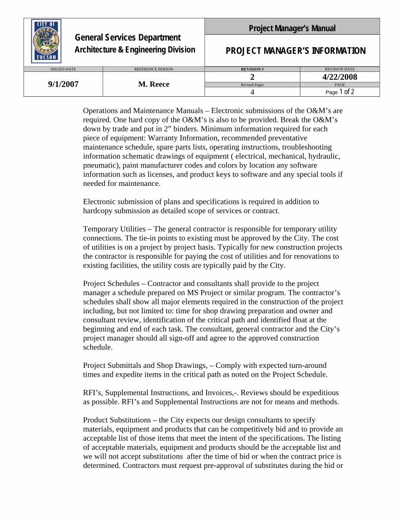
Operations and Maintenance Manuals – Electronic submissions of the O&M’s are required. One hard copy of the O&M’s is also to be provided. Break the O&M’s down by trade and put in 2” binders. Minimum information required for each piece of equipment: Warranty Information, recommended preventative maintenance schedule, spare parts lists, operating instructions, troubleshooting information schematic drawings of equipment ( electrical, mechanical, hydraulic, pneumatic), paint manufacturer codes and colors by location any software information such as licenses, and product keys to software and any special tools if needed for maintenance. Electronic submission of plans and specifications is required in addition to hardcopy submission as detailed scope of services or contract. Temporary Utilities – The general contractor is responsible for temporary utility connections. The tie-in points to existing must be approved by the City. The cost of utilities is on a project by project basis. Typically for new construction projects the contractor is responsible for paying the cost of utilities and for renovations to existing facilities, the utility costs are typically paid by the City. Project Schedules – Contractor and consultants shall provide to the project manager a schedule prepared on MS Project or similar program. The contractor’s schedules shall show all major elements required in the construction of the project including, but not limited to: time for shop drawing preparation and owner and consultant review, identification of the critical path and identified float at the beginning and end of each task. The consultant, general contractor and the City’s project manager should all sign-off and agree to the approved construction schedule. Project Submittals and Shop Drawings, – Comply with expected turn-around times and expedite items in the critical path as noted on the Project Schedule. RFI’s, Supplemental Instructions, and Invoices,-. Reviews should be expeditious as possible. RFI’s and Supplemental Instructions are not for means and methods. Product Substitutions – the City expects our design consultants to specify materials, equipment and products that can be competitively bid and to provide an acceptable list of those items that meet the intent of the specifications. The listing of acceptable materials, equipment and products should be the acceptable list and we will not accept substitutions after the time of bid or when the contract price is determined. Contractors must request pre-approval of substitutes during the bid or
Project Manager’s Manual General Services Department Architecture & Engineering Division PROJECT MANAGER’S INFORMATION
ISSUED DATE REFERENCE PERSON REVISION # REVISION DATE
2 4/22/2008 Revised Pages PAGE 9/1/2007 M. Reece
4 Page 1 of 2
WKSPSTD Rev 11-29-13 MD.doc Page 15 of 15 12/5/2013
The cable tray/ladder shall serve the extend up into the ceiling plenum and/or down into the
ceiling plenum below and continue above primary paths/circulation to provide horizontal
distribution around all core elements, to locations adjacent to all columns and to the location of
pre-set electrical/communication boxes in the floor slab, and to distribute cabling to the perimeter
of the floor where it is then distributed in wire manager, conduit, etc. along the baseboard for
non-raised floor areas.
Indoor Air Quality:
An adequate building outdoor air supply which is protected (from pollutant sources, including
the building’s own exhaust, parking facilities, and outdoor smoking pavilion);
Adequate and effective fresh air delivery to occupants shall be provided.
Properly designed and implemented exhaust systems to service special areas, as well as the
general office spaces. Such exhaust systems shall be designed for compatibility not only with air
intake system(s), but also for compatibility with future development.
Strict pollutant source control, implemented by specification and testing of interior furnishings,
construction materials and installation/construction procedures.
Design of the internal HVAC delivery systems shall incorporate the ability to redirect without
great expense the internal air flows as occupancy and activity patterns change over the life of the
building. The HVAC system shall be designed and balanced to deliver specified airflows to the
occupant’s working locations, taking into account any interference which may be created by
workstations and other furnishings. Occupied stagnant air zones will not be allowed.

REFERENCE PERSON REVISION # REVISION DATE
1 6/18/2008
Revised Pages PAGE
1 Page 1 of 1
PROGRAMMING LABOR
MASTER PLAN LABOR NON-LABOR TOTAL
(Firm) (Discipline)
Project Management
Programming
Design
Cost Est.
Structural
Architectural
Mechanical
Electrical
Civil
Geotechnical
Fueling Systms
Landscape
Communications (RCDD)
Construction Administration
Furnishings
Graphics
Aerial / Surveying
$ $ $ $0
Project Manager’s Manual
FEE PROPOSALISSUED DATE
9/1/2007 Administrator
General Services DepartmentArchitecture & Engineering Division
6/13/97 1
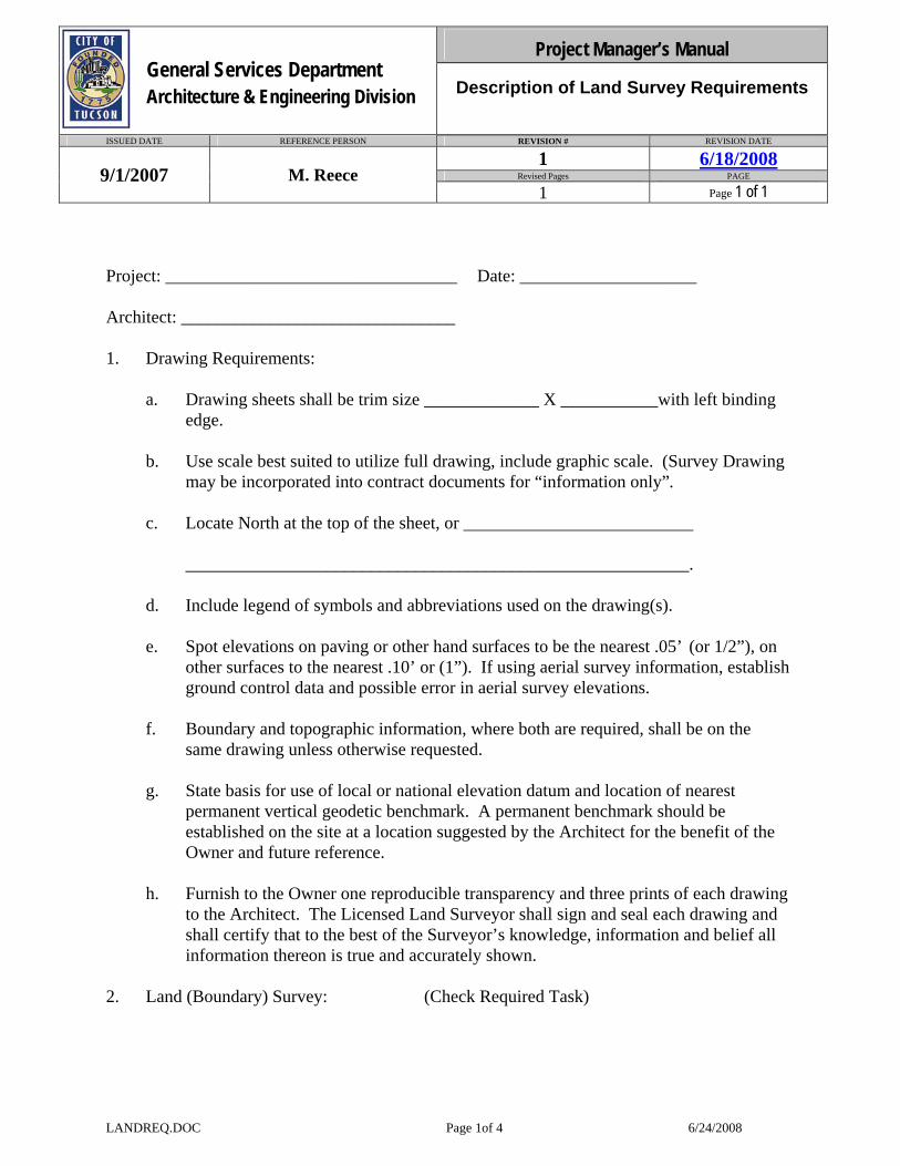
Project Manager’s Manual General Services Department Architecture & Engineering Division Description of Land Survey Requirements
ISSUED DATE REFERENCE PERSON REVISION # REVISION DATE
1 6/18/2008 Revised Pages PAGE 9/1/2007 M. Reece
1 Page 1 of 1
LANDREQ.DOC Page 1of 4 6/24/2008
Project: _________________________________ Date: ____________________ Architect: _______________________________ 1. Drawing Requirements: a. Drawing sheets shall be trim size _____________ X ___________with left binding
edge. b. Use scale best suited to utilize full drawing, include graphic scale. (Survey Drawing
may be incorporated into contract documents for “information only”. c. Locate North at the top of the sheet, or __________________________ _________________________________________________________. d. Include legend of symbols and abbreviations used on the drawing(s). e. Spot elevations on paving or other hand surfaces to be the nearest .05’ (or 1/2”), on
other surfaces to the nearest .10’ or (1”). If using aerial survey information, establish ground control data and possible error in aerial survey elevations.
f. Boundary and topographic information, where both are required, shall be on the
same drawing unless otherwise requested. g. State basis for use of local or national elevation datum and location of nearest
permanent vertical geodetic benchmark. A permanent benchmark should be established on the site at a location suggested by the Architect for the benefit of the Owner and future reference.
h. Furnish to the Owner one reproducible transparency and three prints of each drawing
to the Architect. The Licensed Land Surveyor shall sign and seal each drawing and shall certify that to the best of the Surveyor’s knowledge, information and belief all information thereon is true and accurately shown.
2. Land (Boundary) Survey: (Check Required Task)

Project Manager’s Manual General Services Department Architecture & Engineering Division Description of Land Survey Requirements
ISSUED DATE REFERENCE PERSON REVISION # REVISION DATE
1 6/18/2008 Revised Pages PAGE 9/1/2007 M. Reece
1 Page 2 of 1
LANDREQ.DOC Page 2of 4 6/24/2008
_____ a. Show boundary lines, giving length and bearing (including reference or basis) on each straight line; interior angles; radius, point of tangency and length of curved lines. Where no monument exists, set permanent iron pin (monument) or other suitable permanent monument at property corners; drive pin into ground adequately to prevent movement, mark with wood stake; state on the drawing(s) whether corners were found or set and describe each. If ground monument differs from surveyor’s boundary survey, set new monument pin and state offset.
______ b. Confirm or furnish the legal description which conforms to the Record Title
Boundaries. Prior to making this survey, insofar as possible, acquire data including, but not limited to, deed maps, certificates or abstracts of title, section lines and other boundary line locations in the vicinity.
______ c. Give area in square feet if less than one acre, in acres (to .001 acre) if over an
acre. ______ d. Note identity, jurisdiction and width of adjoining streets and highways, noting
right-of- ways, width and type of pavement. Identify pertinent landmarks. Include platted, but not constructed, streets, highways, etc.
______ e. Plot location of all structures on the property. Plot the structures which are on
adjacent property within 20 feet of subject property. Dimension perimeters in ______ feet and inches to nearest 1/2”;_________ feet and decimals to .05’. State the character and number of stories. Dimension to property lines and/or other buildings. vacant property, including adjacent parcels, shall be noted “Vacant”.
______ f. Show encroachments, including building projections either way across property
lines, easements, right-of-ways, set backs, etc. ______ g. Describe fences and walls including retaining walls. Identify party walls and
locate them with respect to property lines. Show all walks, steps, ramps, planters, etc.
______ h. Show recorded or otherwise known easements and right-of-ways; state the owner
of record of each. ______ i. Note anticipated street widenings.
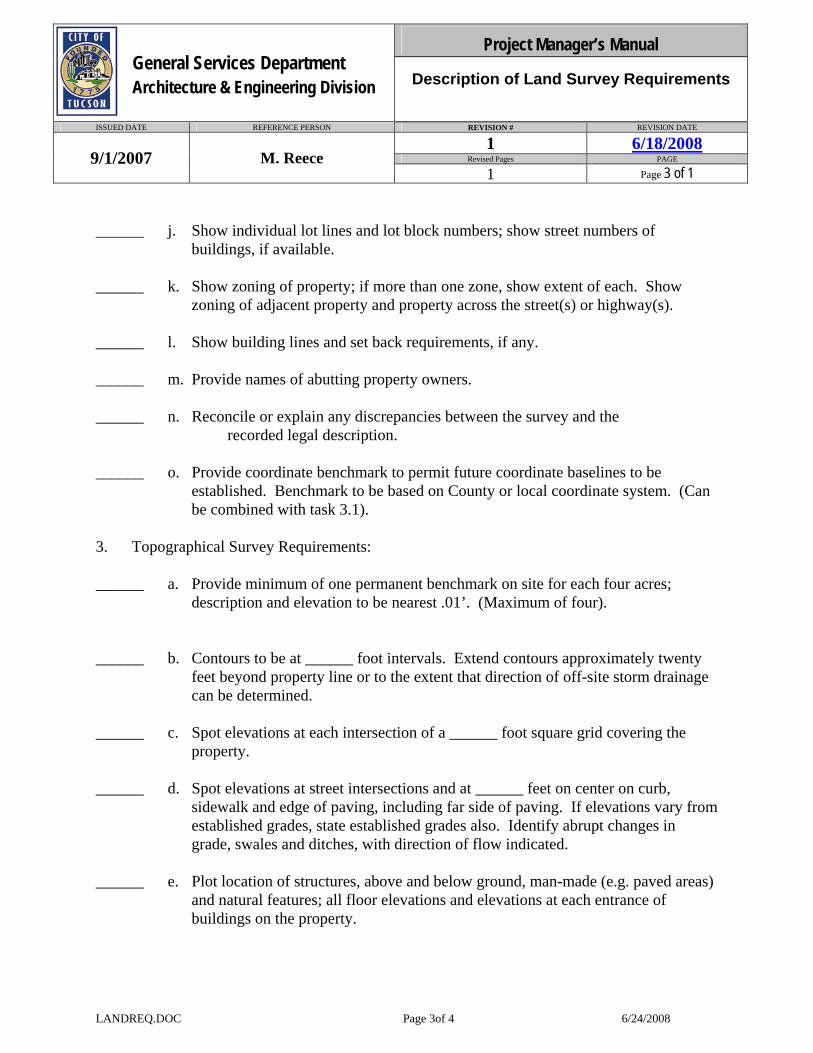
Project Manager’s Manual General Services Department Architecture & Engineering Division Description of Land Survey Requirements
ISSUED DATE REFERENCE PERSON REVISION # REVISION DATE
1 6/18/2008 Revised Pages PAGE 9/1/2007 M. Reece
1 Page 3 of 1
LANDREQ.DOC Page 3of 4 6/24/2008
______ j. Show individual lot lines and lot block numbers; show street numbers of buildings, if available.
______ k. Show zoning of property; if more than one zone, show extent of each. Show
zoning of adjacent property and property across the street(s) or highway(s). ______ l. Show building lines and set back requirements, if any. ______ m. Provide names of abutting property owners. ______ n. Reconcile or explain any discrepancies between the survey and the
recorded legal description. ______ o. Provide coordinate benchmark to permit future coordinate baselines to be
established. Benchmark to be based on County or local coordinate system. (Can be combined with task 3.1).
3. Topographical Survey Requirements: ______ a. Provide minimum of one permanent benchmark on site for each four acres;
description and elevation to be nearest .01’. (Maximum of four). ______ b. Contours to be at ______ foot intervals. Extend contours approximately twenty
feet beyond property line or to the extent that direction of off-site storm drainage can be determined.
______ c. Spot elevations at each intersection of a ______ foot square grid covering the
property. ______ d. Spot elevations at street intersections and at ______ feet on center on curb,
sidewalk and edge of paving, including far side of paving. If elevations vary from established grades, state established grades also. Identify abrupt changes in grade, swales and ditches, with direction of flow indicated.
______ e. Plot location of structures, above and below ground, man-made (e.g. paved areas)
and natural features; all floor elevations and elevations at each entrance of buildings on the property.
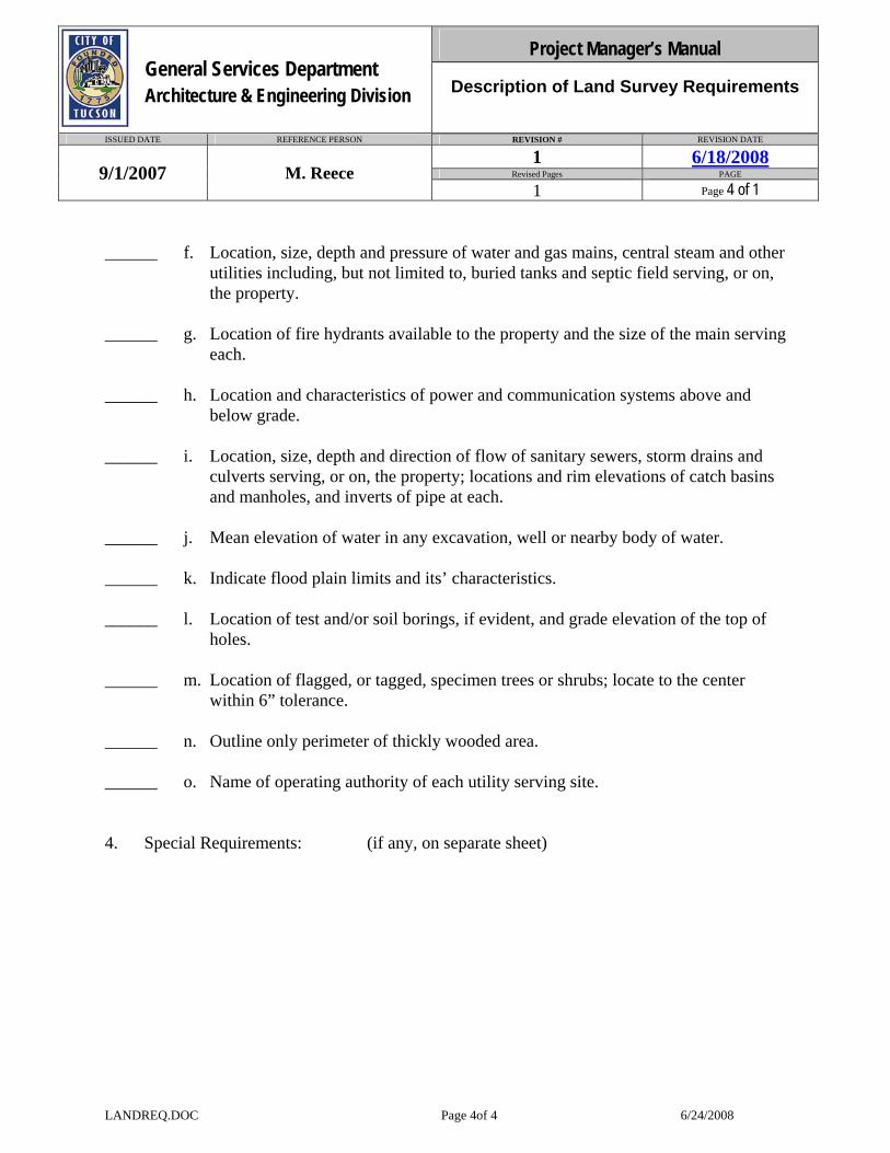
Project Manager’s Manual General Services Department Architecture & Engineering Division Description of Land Survey Requirements
ISSUED DATE REFERENCE PERSON REVISION # REVISION DATE
1 6/18/2008 Revised Pages PAGE 9/1/2007 M. Reece
1 Page 4 of 1
LANDREQ.DOC Page 4of 4 6/24/2008
______ f. Location, size, depth and pressure of water and gas mains, central steam and other utilities including, but not limited to, buried tanks and septic field serving, or on, the property.
______ g. Location of fire hydrants available to the property and the size of the main serving
each. ______ h. Location and characteristics of power and communication systems above and
below grade. ______ i. Location, size, depth and direction of flow of sanitary sewers, storm drains and
culverts serving, or on, the property; locations and rim elevations of catch basins and manholes, and inverts of pipe at each.
______ j. Mean elevation of water in any excavation, well or nearby body of water. ______ k. Indicate flood plain limits and its’ characteristics. ______ l. Location of test and/or soil borings, if evident, and grade elevation of the top of
holes. ______ m. Location of flagged, or tagged, specimen trees or shrubs; locate to the center
within 6” tolerance. ______ n. Outline only perimeter of thickly wooded area. ______ o. Name of operating authority of each utility serving site. 4. Special Requirements: (if any, on separate sheet)
Copy of 01SCHEDULE.doc Page 1 of 2 9/25/2008
PROJECT SCHEDULE Project Schedule: The consultant is required to provide a Microsoft Project schedule in PDF format to include: A. Events that will satisfy each of the project phases through two-year warranty B. Dates each event will start and be completed C. Elements which will hinder normal progress D. Submit updates with each change. Show actual progress plotted against the
original baseline. E. Submit updates with each change showing actual progress plotted against the
original baseline. F. Furnish five copies of original work schedule, along with electronic format,
within 10 days after written Notice to Proceed is issued by City, and thereafter five copies of any approved revisions.
Please include in the schedule the Architecture/Engineering Division’s Three (3) Step Review process (per City Project Manager’s option): 1. Technical Review Meeting with the Consultant Team and each of our respective staff to
coordinate the requirements and concept of the building. 2. Plan review at 100% Design Development at which time each system is reviewed with
written comments to the consultant. 3. Plan review at 100% Construction Documents with written comments to the consultant. The Architecture/Engineering Division reserves the right for final approval of format and content.
Project Manager’s Manual General Services Department Architecture & Engineering Division PROJECT SCHEDULE
ISSUED DATE REFERENCE PERSON REVISION # REVISION DATE
1 6/18/2008 Revised Pages PAGE 9/1/2007 Administrator
1 Page 1 of 1

Copy of 01SCHEDULE.doc Page 2 of 2 9/25/2008
Project Manager’s Manual General Services Department Architecture & Engineering Division SPACE CRITERIA
ISSUED DATE REFERENCE PERSON REVISION # REVISION DATE
1 6/18/2008 Revised Pages PAGE 9/1/2007 Administrator
1 Page 1 of 1
SPACECRI.DOC Page 1 of 3 September 25, 2008
SPACE CRITERIA
GENERAL INFORMATION: Workplace Name: Net Area (S.F.): Reference Person: Number of Occupants: Telephone Number: Date: Source(s) of Information: Please give a simple generic description of the purpose and function of this space: Does this workplace need to be located directly adjacent to or near another space? If so, please list in order of priority (1 highest): Space Directly Priority Number Workspace Name Adjacent Nearby ARCHITECTURAL REQUIREMENTS: Architectural FinishesFloor: Base: Walls: Ceiling: Ceiling Height: Openings: Doors: Type: Material: Glazing: Hardware Considerations: Windows: Window Type Required: Window Covering: Critical dimensional requirements, eg. door height, room width:
Project Manager’s Manual General Services Department Architecture & Engineering Division SPACE CRITERIA
ISSUED DATE REFERENCE PERSON REVISION # REVISION DATE
1 6/18/2008 Revised Pages PAGE 9/1/2007 Administrator
1 Page 2 of 1
SPACECRI.DOC Page 2 of 3 September 25, 2008
Is vehicular access from outside of building required? Are unusual structural loads anticipated? Are raised “computer floors” required? Are there other special architectural considerations? Sound Considerations? Area LayoutProvide a rough sketch of the workplace showing desired furniture, equipment and services locations. General Equipment Requirements How many lineal feet of the following items are required? Countertop Desired Storage cabinets Above Storage Cabinets Below Other Casework Tall Storage Cabinets Open Storage Shelves Other Which of the following items are required and how many are required?: Markerboard lineal feet Chalkboard lineal feet Tackboard lineal feet

pricing negotiations. Where the designer feels approval equals should be allowed this must be approved but the A&E Project Manager.
Project Manager’s Manual General Services Department Architecture & Engineering Division SPACE CRITERIA
ISSUED DATE REFERENCE PERSON REVISION # REVISION DATE
1 6/18/2008 Revised Pages PAGE 9/1/2007 Administrator
1 Page 3 of 1
SPACECRI.DOC Page 3 of 3 September 25, 2008
Project Manager’s Manual General Services Department Architecture & Engineering Division STRUCTURAL
ISSUED DATE REFERENCE PERSON REVISION # REVISION DATE
1 6/18/2008 Revised Pages PAGE 9/1/2007 Administrator
1 Page 1 of 1
STRUCTRU.DOC 1 OF 6 09/25/08
STRUCTURAL
GENERAL:
In addition to meeting the requirements of the referenced codes and standards herein,
the design of the facilities shall meet a special requirements defined by A&E. These
requirements are going to be updated as necessary to eliminate a frequent errors creating
operational, maintenance or safety problems.
REFERENCES AND STANDARDS
1.1. The latest editions of the following codes, specifications, standards and
publications, with applicable supplements and revisions thereto, form a part of this Manual
1.1.1. American Society for Testing Materials (ASTM) A 36 Specification for
Structural Steel.
A 82 Specification for Steel Wire, Plain, for Concrete Reinforcement.
A 108 Specification for Steel Bars, Carbon, Cold-Finished, Standard Quality. A123 Specification for Zinc (Hot-Galvanized) Coatings on Iron and Steel Products.
Project Manager’s Manual General Services Department Architecture & Engineering Division STRUCTURAL
ISSUED DATE REFERENCE PERSON REVISION # REVISION DATE
1 6/18/2008 Revised Pages PAGE 9/1/2007 Administrator
1 Page 2 of 1
STRUCTRU.DOC 2 OF 6 09/25/08
A 153 Specification for Zinc Coating (Hot-Dip) on Iron and Steel Hardware. A 185 Specification for Steel Welded Wire Fabric, Plain, for Concrete
Reinforcement.
A 307 Carbon Steel Externally Threaded Standard Fasteners. A 525 Specification for General Requirements for Steel Sheet, Zinc-Coated (Galvanized) by the Hot-Dip Process. A 563 Specification for Carbon and Alloy Steel Nuts. A 615 Specification for Deformed and Plain Billet-Steel Bars for Concrete Reinforcement. A 706 Specification for Low-Alloy Steel Deformed Bars for Concrete Reinforcement. A 775 Specification for Epoxy-Coated Reinforcing Steel Bars. C 31 Making and Curing Concrete Test Specimens in the Field. C 33 Specifications for Concrete Aggregates. C 39 Test Method for Compressive Strength of Cylindrical Concrete
Specimens.
C 42 Method of Obtaining and Testing Drilled Cores and Sawed Beams
of Concrete.
C 94 Specification for Ready-Mixed Concrete
Project Manager’s Manual General Services Department Architecture & Engineering Division STRUCTURAL
ISSUED DATE REFERENCE PERSON REVISION # REVISION DATE
1 6/18/2008 Revised Pages PAGE 9/1/2007 Administrator
1 Page 3 of 1
STRUCTRU.DOC 3 OF 6 09/25/08
C 138 Method of Test for Unit Weight, Yield and Air Content (Gravimetric) of Concrete. C 143 Method of Test for Slump of Portland Cement Concrete. C 150 Specification for Portland Cement. C 171 Sheet Materials for Curing Concrete. C 172 Method of Sampling Freshly Mixed Concrete. C 192 Method of Making and Curing Concrete Test Specimens in the Laboratory. C 231 Method of Test for Air Content of Freshly Mixed Concrete by the Pressure Method. C 260 Specification for Air-Entraining Admixtures for Concrete.
C 309 Liquid Membrane-Forming Compounds for Curing Concrete. C 311 Test Methods for Sampling and Testing Fly Ash or Natural Pozzolans for Use as a Mineral Admixture in Portland Cement Concrete. C 494 Specification for Chemical Admixtures for Concrete.
C 618 Specification for Fly Ash and Raw or Calcined Natural Pozzolan for Use as a Mineral Admixture in Portland Cement Concrete. C 685 Specification for Concrete Made by Volumetric Batching and Continuous Mixing. C 920 Specification for Elastomeric Joint Sealants.
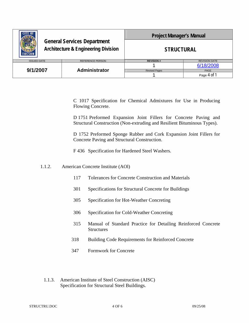
Project Manager’s Manual General Services Department Architecture & Engineering Division STRUCTURAL
ISSUED DATE REFERENCE PERSON REVISION # REVISION DATE
1 6/18/2008 Revised Pages PAGE 9/1/2007 Administrator
1 Page 4 of 1
STRUCTRU.DOC 4 OF 6 09/25/08
C 1017 Specification for Chemical Admixtures for Use in Producing Flowing Concrete. D 1751 Preformed Expansion Joint Fillers for Concrete Paving and Structural Construction (Non-extruding and Resilient Bituminous Types). D 1752 Preformed Sponge Rubber and Cork Expansion Joint Fillers for Concrete Paving and Structural Construction. F 436 Specification for Hardened Steel Washers.
1.1.2. American Concrete Institute (AOl)
117 Tolerances for Concrete Construction and Materials
301 Specifications for Structural Concrete for Buildings
305 Specification for Hot-Weather Concreting
306 Specification for Cold-Weather Concreting
315 Manual of Standard Practice for Detailing Reinforced Concrete Structures
318 Building Code Requirements for Reinforced Concrete
347 Formwork for Concrete
1.1.3. American Institute of Steel Construction (AISC)
Specification for Structural Steel Buildings.

Project Manager’s Manual General Services Department Architecture & Engineering Division STRUCTURAL
ISSUED DATE REFERENCE PERSON REVISION # REVISION DATE
1 6/18/2008 Revised Pages PAGE 9/1/2007 Administrator
1 Page 5 of 1
STRUCTRU.DOC 5 OF 6 09/25/08
Code of Standard Practice for Steel Buildings and Bridges.
1.1.4. Concrete Reinforcing Steel Institute (CRSI) Manual of Standard Practice for Reinforced Concrete Construction
1.1.5. American Welding Society (AWS) Dl .4 Structural Welding Code - Reinforcing Steel Dl .1 Structural Welding Code - Steel
1.1.6. Occupational Safety and Health Administration (OSHA)
Title 29, Part 1910 and Part 1926
1.1.7. Steel Structures Painting Council Steel Structures Painting Manual - Vol. 2 Systems and Specifications
1.1.8. American Concrete Institute (ACI)
1.2. The latest revision of the following are recommended as guides to meet the requirements
of this Manual
1.2.1. American Concrete Institute (AOl)
211.1 Standard Practice for Selecting Proportions for Normal and
Heavyweight Concrete
302 Guide for Concrete Floor and Slab Construction
304 Guide for Measuring, Mixing, Transporting and Placing Concrete
308 Standard Practice for Curing Concrete
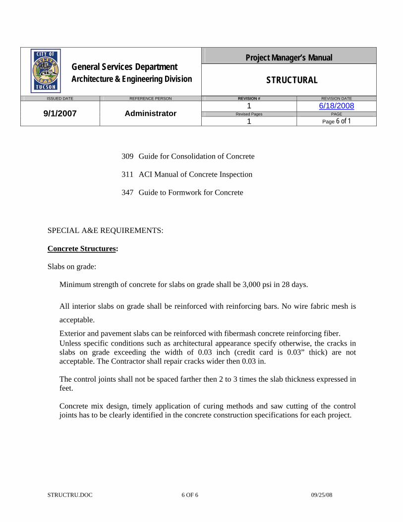
Project Manager’s Manual General Services Department Architecture & Engineering Division STRUCTURAL
ISSUED DATE REFERENCE PERSON REVISION # REVISION DATE
1 6/18/2008 Revised Pages PAGE 9/1/2007 Administrator
1 Page 6 of 1
STRUCTRU.DOC 6 OF 6 09/25/08
309 Guide for Consolidation of Concrete
311 ACI Manual of Concrete Inspection
347 Guide to Formwork for Concrete
SPECIAL A&E REQUIREMENTS: Concrete Structures: Slabs on grade:
Minimum strength of concrete for slabs on grade shall be 3,000 psi in 28 days.
All interior slabs on grade shall be reinforced with reinforcing bars. No wire fabric mesh is
acceptable.
Exterior and pavement slabs can be reinforced with fibermash concrete reinforcing fiber. Unless specific conditions such as architectural appearance specify otherwise, the cracks in slabs on grade exceeding the width of 0.03 inch (credit card is 0.03” thick) are not acceptable. The Contractor shall repair cracks wider then 0.03 in.
The control joints shall not be spaced farther then 2 to 3 times the slab thickness expressed in feet.
Concrete mix design, timely application of curing methods and saw cutting of the control joints has to be clearly identified in the concrete construction specifications for each project.
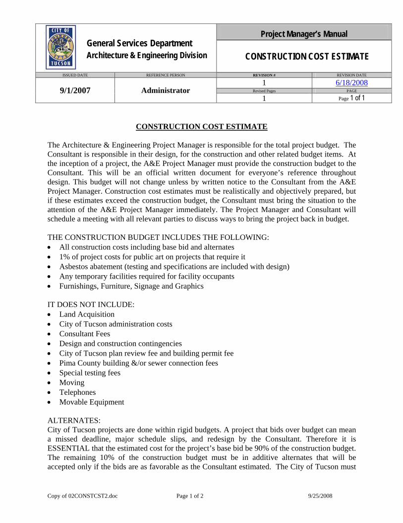
Project Manager’s Manual General Services Department Architecture & Engineering Division CONSTRUCTION COST ESTIMATE
ISSUED DATE REFERENCE PERSON REVISION # REVISION DATE
1 6/18/2008 Revised Pages PAGE 9/1/2007 Administrator
1 Page 1 of 1
Copy of 02CONSTCST2.doc Page 1 of 2 9/25/2008
CONSTRUCTION COST ESTIMATE The Architecture & Engineering Project Manager is responsible for the total project budget. The Consultant is responsible in their design, for the construction and other related budget items. At the inception of a project, the A&E Project Manager must provide the construction budget to the Consultant. This will be an official written document for everyone’s reference throughout design. This budget will not change unless by written notice to the Consultant from the A&E Project Manager. Construction cost estimates must be realistically and objectively prepared, but if these estimates exceed the construction budget, the Consultant must bring the situation to the attention of the A&E Project Manager immediately. The Project Manager and Consultant will schedule a meeting with all relevant parties to discuss ways to bring the project back in budget. THE CONSTRUCTION BUDGET INCLUDES THE FOLLOWING: • All construction costs including base bid and alternates • 1% of project costs for public art on projects that require it • Asbestos abatement (testing and specifications are included with design) • Any temporary facilities required for facility occupants • Furnishings, Furniture, Signage and Graphics IT DOES NOT INCLUDE: • Land Acquisition • City of Tucson administration costs • Consultant Fees • Design and construction contingencies • City of Tucson plan review fee and building permit fee • Pima County building &/or sewer connection fees • Special testing fees • Moving • Telephones • Movable Equipment ALTERNATES: City of Tucson projects are done within rigid budgets. A project that bids over budget can mean a missed deadline, major schedule slips, and redesign by the Consultant. Therefore it is ESSENTIAL that the estimated cost for the project’s base bid be 90% of the construction budget. The remaining 10% of the construction budget must be in additive alternates that will be accepted only if the bids are as favorable as the Consultant estimated. The City of Tucson must
Project Manager’s Manual General Services Department Architecture & Engineering Division CONSTRUCTION COST ESTIMATE
ISSUED DATE REFERENCE PERSON REVISION # REVISION DATE
1 6/18/2008 Revised Pages PAGE 9/1/2007 Administrator
1 Page 2 of 1
Copy of 02CONSTCST2.doc Page 2 of 2 9/25/2008
consider alternates in order, therefore, priorities must be established with the City of Tucson. Alternates must be clearly identified on the drawings and noted on the cover page. THE PROJECT MANAGER SHALL THEN PREPARE THE PROJECT BUDGET TRACKING FORM See: e:\forms\projtrac.xls
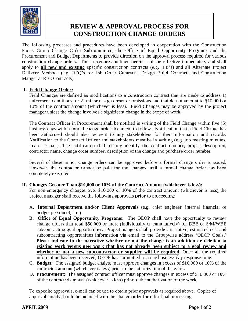
REVIEW & APPROVAL PROCESS FOR
CONSTRUCTION CHANGE ORDERS The following processes and procedures have been developed in cooperation with the Construction Focus Group Change Order Subcommittee, the Office of Equal Opportunity Programs and the Procurement and Budget Departments to provide direction on the approval process required for various construction change orders. The procedures outlined herein shall be effective immediately and shall apply to all new and existing specific construction contracts (e.g. IFB’s) and all Alternate Project Delivery Methods (e.g. RFQ’s for Job Order Contracts, Design Build Contracts and Construction Manger at Risk Contracts). I. Field Change-Order:
Field Changes are defined as modifications to a construction contract that are made to address 1) unforeseen conditions, or 2) minor design errors or omissions and that do not amount to $10,000 or 10% of the contract amount (whichever is less). Field Changes may be approved by the project manager unless the change involves a significant change in the scope of work. The Contract Officer in Procurement shall be notified in writing of the Field Change within five (5) business days with a formal change order document to follow. Notification that a Field Change has been authorized should also be sent to any stakeholders for their information and records. Notification to the Contract Officer and stakeholders must be in writing (e.g. job meeting minutes, fax or e-mail). The notification shall clearly identify the contract number, project description, contractor name, change order number, description of the change and purchase order number. Several of these minor change orders can be approved before a formal change order is issued. However, the contractor cannot be paid for the changes until a formal change order has been completely executed.
II. Changes Greater Than $10,000 or 10% of the Contract Amount (whichever is less): For non-emergency changes over $10,000 or 10% of the contract amount (whichever is less) the project manager shall receive the following approvals prior to proceeding: A. Internal Department and/or Client Approvals (e.g. chief engineer, internal financial or
budget personnel, etc.) B. Office of Equal Opportunity Programs: The OEOP shall have the opportunity to review
change orders that total $50,000 or more (individually or cumulatively) for DBE or S/M/WBE subcontracting goal opportunities. Project mangers shall provide a narrative, estimated cost and subcontracting opportunities information via email to the Groupwise address ‘OEOP Goals.’ Please indicate in the narrative whether or not the change is an addition or deletion to existing work versus new work that has not already been subject to a goal review and whether or not a new subcontractor or supplier will be required. Once all the required information has been received, OEOP has committed to a one business day response time.
C. Budget: The assigned budget analyst must approve changes in excess of $10,000 or 10% of the contracted amount (whichever is less) prior to the authorization of the work.
D. Procurement: The assigned contract officer must approve changes in excess of $10,000 or 10% of the contracted amount (whichever is less) prior to the authorization of the work.
To expedite approvals, e-mail can be use to obtain prior approvals as required above. Copies of approval emails should be included with the change order form for final processing.
APRIL 2009 Page 1 of 2
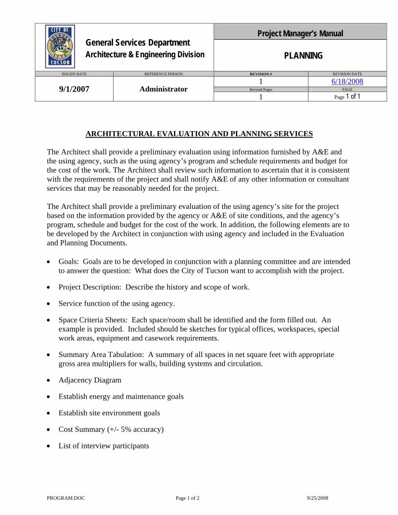
Project Manager’s Manual General Services Department Architecture & Engineering Division PLANNING
ISSUED DATE REFERENCE PERSON REVISION # REVISION DATE
1 6/18/2008 Revised Pages PAGE 9/1/2007 Administrator
1 Page 1 of 1
PROGRAM.DOC Page 1 of 2 9/25/2008
ARCHITECTURAL EVALUATION AND PLANNING SERVICES
The Architect shall provide a preliminary evaluation using information furnished by A&E and the using agency, such as the using agency’s program and schedule requirements and budget for the cost of the work. The Architect shall review such information to ascertain that it is consistent with the requirements of the project and shall notify A&E of any other information or consultant services that may be reasonably needed for the project. The Architect shall provide a preliminary evaluation of the using agency’s site for the project based on the information provided by the agency or A&E of site conditions, and the agency’s program, schedule and budget for the cost of the work. In addition, the following elements are to be developed by the Architect in conjunction with using agency and included in the Evaluation and Planning Documents. • Goals: Goals are to be developed in conjunction with a planning committee and are intended
to answer the question: What does the City of Tucson want to accomplish with the project. • Project Description: Describe the history and scope of work. • Service function of the using agency. • Space Criteria Sheets: Each space/room shall be identified and the form filled out. An
example is provided. Included should be sketches for typical offices, workspaces, special work areas, equipment and casework requirements.
• Summary Area Tabulation: A summary of all spaces in net square feet with appropriate
gross area multipliers for walls, building systems and circulation. • Adjacency Diagram • Establish energy and maintenance goals • Establish site environment goals • Cost Summary (+/- 5% accuracy) • List of interview participants
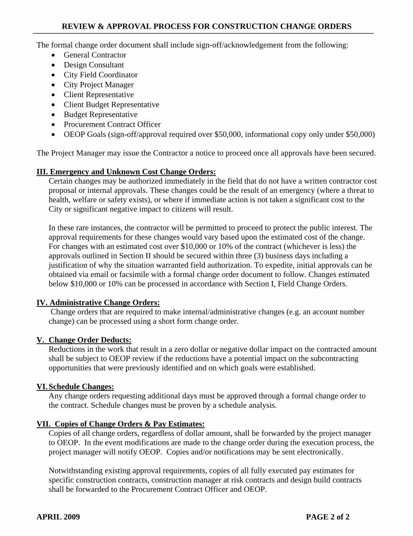
REVIEW & APPROVAL PROCESS FOR CONSTRUCTION CHANGE ORDERS
The formal change order document shall include sign-off/acknowledgement from the following:
• General Contractor • Design Consultant • City Field Coordinator • City Project Manager • Client Representative • Client Budget Representative • Budget Representative • Procurement Contract Officer • OEOP Goals (sign-off/approval required over $50,000, informational copy only under $50,000)
The Project Manager may issue the Contractor a notice to proceed once all approvals have been secured. III. Emergency and Unknown Cost Change Orders:
Certain changes may be authorized immediately in the field that do not have a written contractor cost proposal or internal approvals. These changes could be the result of an emergency (where a threat to health, welfare or safety exists), or where if immediate action is not taken a significant cost to the City or significant negative impact to citizens will result. In these rare instances, the contractor will be permitted to proceed to protect the public interest. The approval requirements for these changes would vary based upon the estimated cost of the change. For changes with an estimated cost over $10,000 or 10% of the contract (whichever is less) the approvals outlined in Section II should be secured within three (3) business days including a justification of why the situation warranted field authorization. To expedite, initial approvals can be obtained via email or facsimile with a formal change order document to follow. Changes estimated below $10,000 or 10% can be processed in accordance with Section I, Field Change Orders.
IV. Administrative Change Orders: Change orders that are required to make internal/administrative changes (e.g. an account number change) can be processed using a short form change order.
V. Change Order Deducts:
Reductions in the work that result in a zero dollar or negative dollar impact on the contracted amount shall be subject to OEOP review if the reductions have a potential impact on the subcontracting opportunities that were previously identified and on which goals were established.
VI. Schedule Changes: Any change orders requesting additional days must be approved through a formal change order to the contract. Schedule changes must be proven by a schedule analysis.
VII. Copies of Change Orders & Pay Estimates: Copies of all change orders, regardless of dollar amount, shall be forwarded by the project manager
to OEOP. In the event modifications are made to the change order during the execution process, the project manager will notify OEOP. Copies and/or notifications may be sent electronically.
Notwithstanding existing approval requirements, copies of all fully executed pay estimates for
specific construction contracts, construction manager at risk contracts and design build contracts shall be forwarded to the Procurement Contract Officer and OEOP.
APRIL 2009 PAGE 2 of 2

Construction Closeout
Check off List
Page 1
( Note: use TAB to move through document ) Date of
Completion Responsible
Party DSD Final Inspections (check online) PC
Certificate of Occupancy / Letter of Completion PC (data from GC) 1 copy to Project Manager (PM) PC 1 copy to Using Dept PC 1 copy to Construction File PC Original is picture framed and posted in building PC
Substantial Completion Walk Through PC 1st Punch List Completion Check PC Facilities shop supervisor’s notification PC IT (communications) PC Consultant PC Using Dept PC Project Manager (PM) PC Other: 2nd Punch List Completion Check PC Facilities shop supervisor’s notification PC IT (communications) PC Consultant PC Using Dept PC Project manager (PM) PC Other:
Final Walk Through PC Facilities shop supervisor’s notification PC IT (communications) PC Consultant PC Using Dept PC Project Manager (PM) PC Other:
Utilities ( Startup & Change Over ) PC (from GC to COT) Electrical PC (from GC to COT) Water PC (from GC to COT) Gas PC (from GC to COT)
Telephones PC (from GC to COT) Fiber Optics PC (from GC to COT)
DES # FM # FACILITY DATE COMMENTS
PROJECT NAME …
PROJECT MANAGER … PROJECT COORDINATOR …
CONTRACTOR … CONTRACTOR PHONE NUMBER
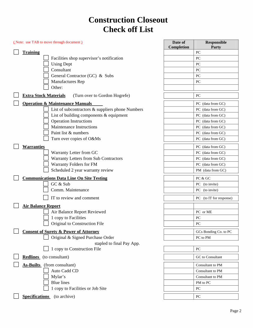
Construction Closeout
Check off List
Page 2
( Note: use TAB to move through document ) Date of
Completion Responsible
Party Training PC
Facilities shop supervisor’s notification PC Using Dept PC Consultant PC
General Contractor (GC) & Subs PC Manufactures Rep PC Other:
Extra Stock Materials (Turn over to Gordon Hogrefe) PC
Operation & Maintenance Manuals PC (data from GC) List of subcontractors & suppliers phone Numbers PC (data from GC) List of building components & equipment PC (data from GC)
Operation Instructions PC (data from GC) Maintenance Instructions PC (data from GC) Paint list & numbers PC (data from GC) Turn over copies of O&Ms PC (data from GC)
Warranties PC (data from GC) Warranty Letter from GC PC (data from GC) Warranty Letters from Sub Contractors PC (data from GC) Warranty Folders for FM PC (data from GC) Scheduled 2 year warranty review PM (data from GC)
Communications Data Line On Site Testing PC & GC GC & Sub PC (to invite) Comm. Maintenance PC (to invite)
IT to review and comment PC (to IT for response)
Air Balance Report Air Balance Report Reviewed PC or ME 1 copy to Facilities PC Original to Construction File PC
Consent of Surety & Power of Attorney GCs Bonding Co. to PC Original & Signed Purchase Order PC to PM stapled to final Pay App. 1 copy to Construction File PC
Redlines (to consultant) GC to Consultant
As-Builts (from consultant) Consultant to PM Auto Cadd CD Consultant to PM Mylar’s Consultant to PM Blue lines PM to PC 1 copy to Facilities or Job Site PC
Specifications (to archive) PC

Construction Closeout
Check off List
Page 3
( Note: use TAB to move through document ) Date of
Completion Responsible
Party
Keys PC (keys from GC) Signed Request Form PC (form signed by GC) Returned Keys (to lock shop) PC
Re-Keying of New Facility PC & Lock Shop
Substitute Securities Final Payment ?
Commissioning Report Review Report (add items to punchlist as needed) PC or ME 1 copy to Facilities PC Original to Construction File PC
Commissioning Review PC Schedule or Task 10 month post occupancy PC commissioning review
Controls Mapping Invitation PC Facilities Mechanical Dept (EMCS section) PC Climatec (controls contractor) PC Using Dept PC General Contractor (GC) PC Project Manager (PM) PC Other: Letter from (controls contractor) ?
Construction Evaluation PC 1 copy to Using Dept PC Signed copy from Using Dept. User to PC
Consultant Evaluation PC 1 copy to Using Dept PC Signed copy from Using Dept User to PC
Contractor Post Project Evaluation Filled Out PC 1 copy to Using Dept PC Signed copy from Using Dept User to PC
Consultant Post Project Evaluation Filled Out PC 1 copy to Using Dept PC Signed copy from Using Dept User to PC
Finalized Permits (copies in construction file) PC
Final Project Tracking and Benchmarking PM
Financial Information Completed PM
Design LEED Certification Submittal (verified by PM) Consultant to PM
Construction LEED Certification Submittal (verified by PM) Consultant to PM
Final Submission LEED (verified by PM) Consultant to PM
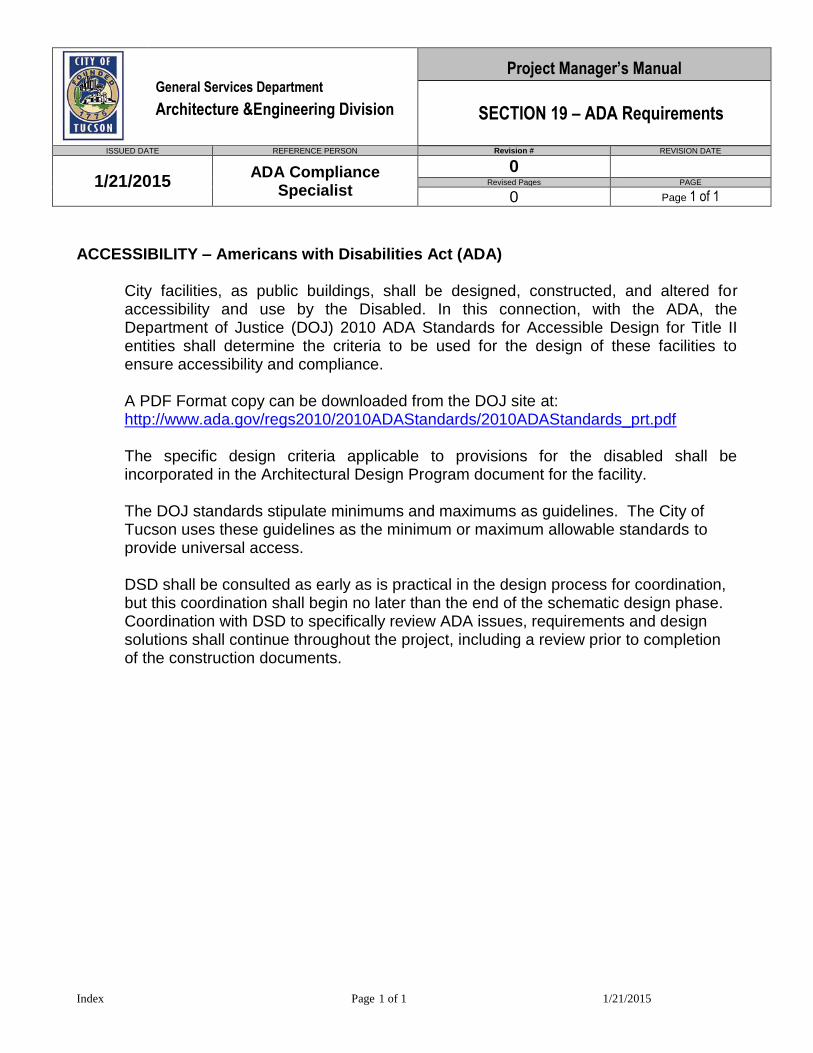
General Services Department
Architecture &Engineering Division
Project Manager’s Manual
SECTION 19 – ADA Requirements
ISSUED DATE REFERENCE PERSON Revision # REVISION DATE
1/21/2015 ADA Compliance
Specialist
0 Revised Pages PAGE
0 Page 1 of 1
Index Page 1 of 1 1/21/2015
ACCESSIBILITY – Americans with Disabilities Act (ADA)
City facilities, as public buildings, shall be designed, constructed, and altered for accessibility and use by the Disabled. In this connection, with the ADA, the Department of Justice (DOJ) 2010 ADA Standards for Accessible Design for Title II entities shall determine the criteria to be used for the design of these facilities to ensure accessibility and compliance.
A PDF Format copy can be downloaded from the DOJ site at: http://www.ada.gov/regs2010/2010ADAStandards/2010ADAStandards_prt.pdf The specific design criteria applicable to provisions for the disabled shall be incorporated in the Architectural Design Program document for the facility.
The DOJ standards stipulate minimums and maximums as guidelines. The City of Tucson uses these guidelines as the minimum or maximum allowable standards to provide universal access. DSD shall be consulted as early as is practical in the design process for coordination, but this coordination shall begin no later than the end of the schematic design phase. Coordination with DSD to specifically review ADA issues, requirements and design solutions shall continue throughout the project, including a review prior to completion of the construction documents.
Project Manager’s Manual General Services Department
Architecture & Engineering Division WORK ORDER ESTIMATE INSTRUCTIONS
ISSUED DATE REFERENCE PERSON
PREPARING THE ESTIMATE:
1. Receive the WOE. Determine/verify that the WOE has been logged in by FM-ESTIMATE. If so, the WOE has a tracking number. If the WOE does not have a tracking number, route the WOE to FM-ESTIMATE for processing. 2. Read the Customer’s (Client’s) Scope of Work (SOW) in the WOE and gain an understanding of what the Client wants. 3. Call the Customer and discuss the SOW in detail with particular attention to correcting any misconceptions.
4. If an existing facility, retrieve archive documents. Make copies of pertinent documents to aid during your site survey. 5. If, in your estimate, the entire WOE process will take 4 hours or more of A&E Division’s time, request that the Client provide you with an account number. (This can be done at any time during the WOE process.) 6. Familiarize yourself with the existing facility through the archive documents, as related to the SOW, before you make a site visit. 7. Meet with the Customer on site; confirm the budget and schedule; understand the entire SOW. 8. Write a brief, but thorough, description of the project that fits within the DETAILS OF WORK TO BE PERFORMED on the WOE form. 9. Decide what information, resources and activities are required to develop a valid budget and schedule. Determine:
• Is a Permit required? • Is the JOC method of contracting the best way to hire a contractor for this project? • Can the JOC do the construction drawings through the design portion of his contract? • Can the JOC get the permit? • Do you need to hire a consultant to do the design and get the permit? • Is Means Cost Estimating Manuals adequate for estimating construction costs? • Are there in house experts you can access?
REVISION # REVISION DATE
2 5/6/2008 Revised Pages PAGE 12/1/2007 F. ELLIOTT
1 of 11 Page

10. Assemble information and calculate the construction cost (use AE ESTIMATE form.xls at E:\oooAEmiscform\AE Estimate form.xls.) 11. Estimate the soft costs or let the estimating spreadsheet calculate soft costs, such as Permit fees, GSD FM & AE Admin costs, etc. 12. Select and use an appropriate Contingency percentage as developed for the scope of the project. Example: if selective demolition is involved where unknown conditions may be present – use a higher Contingency than you normally would. 13. Review the final project costs and construction costs with the size of the project. Verify quantities, unit costs and spreadsheet formulas. Small projects usually cost more per unit than larger projects. 14. Perform a peer review by sending copies of your draft WOE to your co-workers with a comment/question sheet with a reply due date. Resolve any comments or questions with each individual. 15. Send the WOE to the AE administrator for review and corrections, if any, and the administrator will process the WOE to the Customer through FM-ESTIMATE. 16. Verify with the Customer in 5 to 8 days if they have received the WOE and, if so, do they have any questions? 17. The Customer may want you to adjust the WOE and the original SOW to fit the Customer’s budget. If so, notify FM-ESTIMATE there will be a revised WOE and proceed again from item #8 above. 18. Once you have an approved WOE, with the Customer’s signature and account number, set-up the project as usual, include a schedule, budget tracking, and add the project to the A&E ACCESS database.
INTRODUCTION TO SOLAR READINESS GUIDELINES FOR CITY BUILDINGS These guidelines were drafted by CH2MHill, consultants hired through the City of Tucson’s Solar America Cities grant in 2010. The intention is to integrate these solar readiness guidelines into the Architecture & Engineering (A&E) Standards and Project Managers Manual and place them on the A&E website so that all future City-funded buildings will be solar ready. In order to ensure that New and Renovated City of Tucson Buildings comply with the Mayor and Council required Sustainable Energy Standard and specifically the requirement that at least 5% of the buildings energy usage be offset by solar energy utilization we have issued these Solar Readiness Guidelines for City Buildings. In addition to the 5% energy offset it is the City of Tucson’s desire to have all buildings designed and built for future solar energy utilization. These guidelines provide direction for ensuring the City’s desired result. By preparing all city buildings for future installation of solar panels, the City of Tucson will continue the pro-solar policies in place since 1999 which lead to Tucson becoming a US DOE Solar America City. This approach is also consistent with suggested actions of the City’s Climate Change Committee, which has recommended continued adoption of solar technology on City facilities. By looking ahead to a time when all possible City rooftops are used for solar energy generation, the City continues this tradition. These Guidelines explain the necessary detail to implement such a policy. February, 2012
Project Manager’s Manual General Services Department Architecture & Engineering Division Solar Readiness Guidelines
ISSUED DATE REFERENCE PERSON REVISION # REVISION DATE
Revised Pages PAGE March 1, 2012 Administrator
Page 1 of 32
F I N A L R E P O R T
Solar Photovoltaic (PV) Readiness Guideline
for
Municipal Buildings
Facilities Management Division General Services Department
City of Tucson, AZ
Prepared for
City of Tucson
17 June 2010/ 11 February 2011
Prepared by
9191 S. Jamaica St. Englewood, CO 80112
(303) 771-0900 Prepared by: Eric Sandoval
With additional edits by City of Tucson staff

i
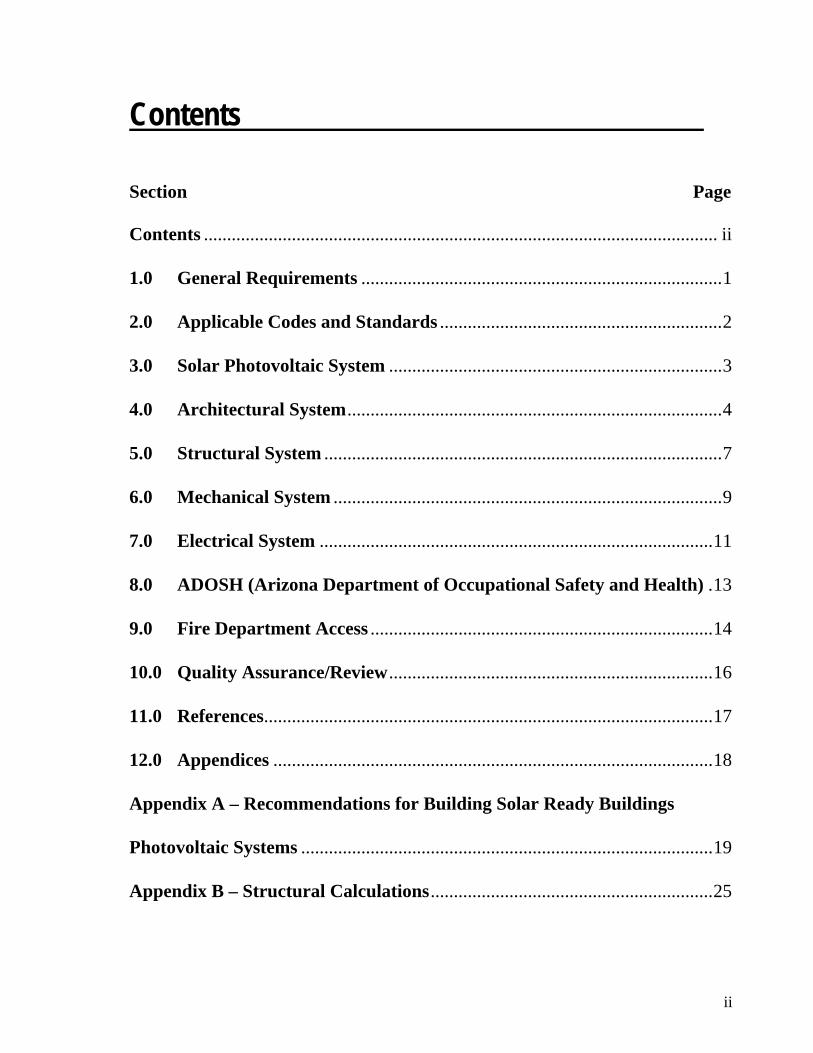
ii
Contents
Section Page
Contents ............................................................................................................... ii
1.0 General Requirements ..............................................................................1
2.0 Applicable Codes and Standards .............................................................2
3.0 Solar Photovoltaic System ........................................................................3
4.0 Architectural System.................................................................................4
5.0 Structural System ......................................................................................7
6.0 Mechanical System ....................................................................................9
7.0 Electrical System .....................................................................................11
8.0 ADOSH (Arizona Department of Occupational Safety and Health) .13
9.0 Fire Department Access ..........................................................................14
10.0 Quality Assurance/Review......................................................................16
11.0 References.................................................................................................17
12.0 Appendices ...............................................................................................18
Appendix A – Recommendations for Building Solar Ready Buildings
Photovoltaic Systems .........................................................................................19
Appendix B – Structural Calculations.............................................................25
Project Manager’s Manual General Services Department Architecture & Engineering Division PLANNING
ISSUED DATE REFERENCE PERSON REVISION # REVISION DATE
1 6/18/2008 Revised Pages PAGE 9/1/2007 Administrator
1 Page 2 of 1
PROGRAM.DOC Page 2 of 2 9/25/2008
• Deliverables: The final document is to be reproduced in black and white, bound in 81/2 x 11 format, and ten (10) copies (unless otherwise noted in the contract) distributed to the City of Tucson Architecture & Engineering office, which will in turn distribute copies to each of the user departments and agencies. Also, include one (1) set of black and white reproducible plans. The cover sheets on plans and booklets should include the project name and address, date, and approval signatures for each department user group and Architecture & Engineering Division.
A&E reserves the right for final approval of format and content.

iii
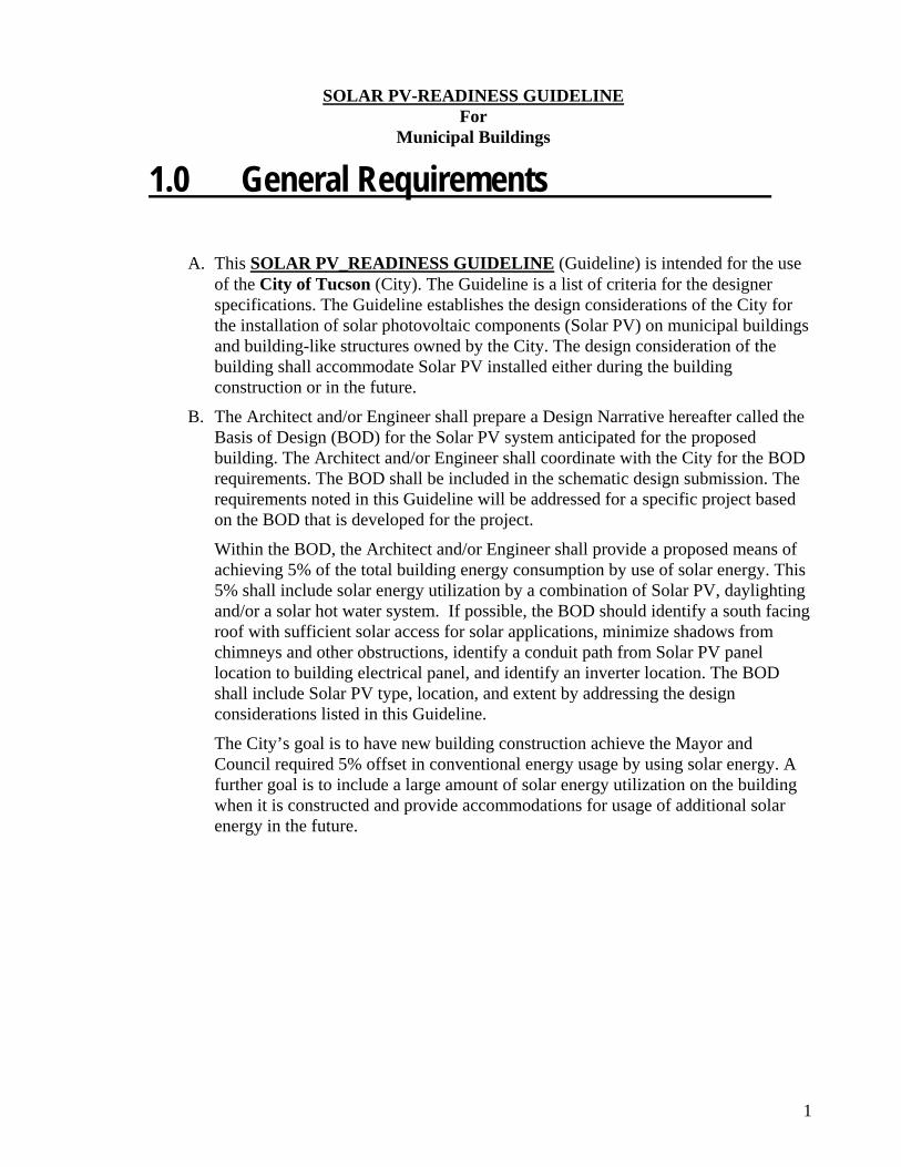
1
SOLAR PV-READINESS GUIDELINE For
Municipal Buildings
1.0 General Requirements
A. This SOLAR PV_READINESS GUIDELINE (Guideline) is intended for the use of the City of Tucson (City). The Guideline is a list of criteria for the designer specifications. The Guideline establishes the design considerations of the City for the installation of solar photovoltaic components (Solar PV) on municipal buildings and building-like structures owned by the City. The design consideration of the building shall accommodate Solar PV installed either during the building construction or in the future.
B. The Architect and/or Engineer shall prepare a Design Narrative hereafter called the Basis of Design (BOD) for the Solar PV system anticipated for the proposed building. The Architect and/or Engineer shall coordinate with the City for the BOD requirements. The BOD shall be included in the schematic design submission. The requirements noted in this Guideline will be addressed for a specific project based on the BOD that is developed for the project.
Within the BOD, the Architect and/or Engineer shall provide a proposed means of achieving 5% of the total building energy consumption by use of solar energy. This 5% shall include solar energy utilization by a combination of Solar PV, daylighting and/or a solar hot water system. If possible, the BOD should identify a south facing roof with sufficient solar access for solar applications, minimize shadows from chimneys and other obstructions, identify a conduit path from Solar PV panel location to building electrical panel, and identify an inverter location. The BOD shall include Solar PV type, location, and extent by addressing the design considerations listed in this Guideline.
The City’s goal is to have new building construction achieve the Mayor and Council required 5% offset in conventional energy usage by using solar energy. A further goal is to include a large amount of solar energy utilization on the building when it is constructed and provide accommodations for usage of additional solar energy in the future.
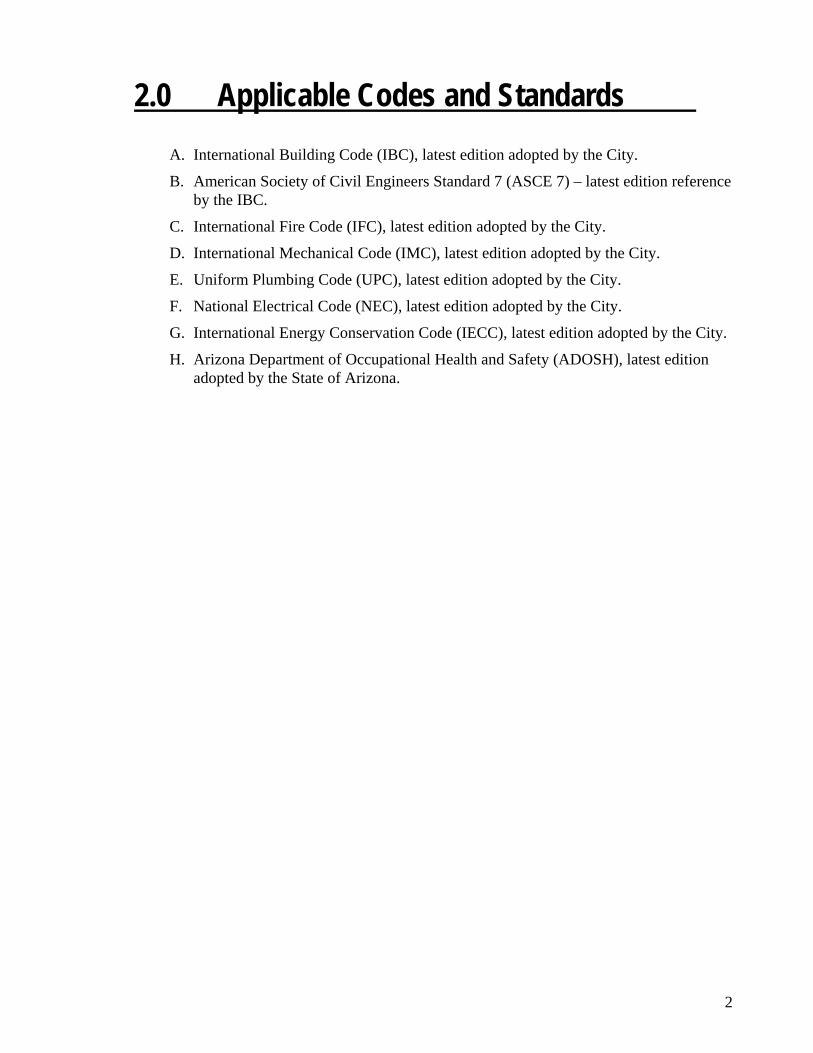
2
2.0 Applicable Codes and Standards A. International Building Code (IBC), latest edition adopted by the City.
B. American Society of Civil Engineers Standard 7 (ASCE 7) – latest edition reference by the IBC.
C. International Fire Code (IFC), latest edition adopted by the City.
D. International Mechanical Code (IMC), latest edition adopted by the City.
E. Uniform Plumbing Code (UPC), latest edition adopted by the City.
F. National Electrical Code (NEC), latest edition adopted by the City.
G. International Energy Conservation Code (IECC), latest edition adopted by the City.
H. Arizona Department of Occupational Health and Safety (ADOSH), latest edition adopted by the State of Arizona.
3
3.0 Solar Photovoltaic System A. System Description
1. This provision is intended to provide direction on the decisions of the City in regards to the types of Solar PV covered. As technology develops in this area, it will be necessary to update this Guideline in relation to these new technologies. The criteria below give reference to specific Solar PV system types reviewed when compiling this Guideline. The revision and date of this Guideline will track the revisions as new technologies become available, as this Guideline incorporates and interfaces with the current codes and standards. It is the intent of this section to establish alignment of the City installations with the current codes and standards adopted by the City specific to Solar PV installations to ensure that the installation is in compliance with the building systems. It is also the intent of this section that building systems accommodate future Solar PV systems During schematic design, potential solar device location areas should be identified and protected unless cost prohibitive or in conflict with other City policies.
2. Solar Photovoltaic System shall be defined as described in the NEC. The total components and subsystems that, in combination, convert solar energy into electric energy suitable for connection to utilization load.
B. Design Criteria
1. Skylight Mullion Systems – These systems utilize framed PV modules or frameless PV module laminates with building integration into skylights as a translucent and/or opaque shading device.
2. Curtain Wall Systems – These systems utilize framed PV modules or frameless PV module laminates with building integration into curtain walls as a translucent and/or opaque shading device.
3. Non-penetrating Roof Mounting Systems – These systems use weight (ballast), laminate adhesives, are self-ballasting or are combinations thereof to withstand wind and seismic loading. This system is typically installed on low slope flat roofs with less than ½:12 pitch.
4. Penetrating Roof Mounting Systems – These systems anchor the PV racks to building structure to withstand wind and seismic loading.
5. Building integrated PV-photovoltaic cells incorporated into shingles, awnings, windows or other parts of the building envelope.
4
4.0 Architectural System A. System Description
1. This provision is intended to provide direction on the decisions of the City in regards to architectural systems. The criteria below give reference to specific code provisions described in the IBC. It is the intent of this section to establish alignment of the City installations with the IBC specific to Solar PV installations to ensure that the installation is in compliance with the building architectural systems and to ensure that the building architectural system is designed to accommodate a Solar PV system
B. Design Criteria
1. The building exterior envelope, includes but is not limited to, weather protection, fire classification and appearance in regards to roof assembly and exterior wall envelope. The building exterior envelop design regulated by the IBC shall accommodate the ability to install Solar PV systems while meeting the provisions of the IBC. Other provisions of the IBC may apply as appropriate to the Solar PV design of the building. When installing the Solar PV systems described in section 3.0 above, care should be given to the requirements of the IBC.
a. Roofing
i. Moisture Protection - Solar PV systems shall be designed, installed and maintained in a manner consistent with IBC section 1503. The roof assembly integrity shall be preserved to prevent moisture, rodents and insects from entering the wall and roof at anchorage points of Solar PV systems. Employment of flashing, coping, and roof drainage shall be used as described in section 1503 to meet the requirements of preventing moisture from penetrating the weather protection attributes of the roof assembly.
ii. Fire Classification – Solar PV systems shall be designed, installed and maintained in a manner consistent with IBC section 1505. The roof assembly integrity shall be preserved related to fire classification. The installation of the Solar PV systems shall not remove the elements of the roof assembly that provide the fire classification.
5
iii. Appearance – Solar PV systems shall be designed, installed and maintained in a manner consistent with IBC sections 1507 and 1509. The installation methods of roofing materials described in 1507 shall be preserved with the installation. The requirements described in 1509 related to rooftop structures shall apply to Solar PV systems.
b. Walls
i. Moisture Protection - Solar PV systems shall be designed, installed and maintained in a manner consistent with IBC sections 1403, 1404 and 1405. The exterior wall envelope integrity shall be preserved to prevent moisture from entering the wall at anchorage points of Solar PV systems. Employment of flashing, coping, and wall drainage shall be used as described in sections 1403, 1404 and 1405 to meet the requirements of preventing moisture, rodents and insects from penetrating the weather protection attributes of the exterior wall envelope.
ii. Fire Classification – Solar PV systems shall be designed, installed and maintained in a manner consistent with IBC section 1406. The fire classification of the exterior wall envelope shall be preserved. The installation of the Solar PV systems shall not remove the elements of the exterior wall envelope that provide the fire classification.
C. Coordination
1. The building architectural system should be designed and installed in coordination with a future Solar PV system as determined by the BOD. The building architectural system should be designed to accommodate the Solar PV system in terms of its power capacity, location and ease of installation. Architectural features to be located on the roof shall be installed to provide sufficient area for the Solar PV system based on the BOD. The following items shall be included but not limited to:
a. The design for roof fire resistance and worker access at roof edge conditions shall consider how the Solar PV system will be mounted on the roof as determined by the BOD.
b. The design for the building scale form and identification shall consider how the Solar PV system will be mounted on the building form as determined by the BOD. The roof/wall surface where the Solar PV array is to be located should be oriented directly toward the solar resources (to the south).

6
c. The design for environmental lighting of interior spaces with natural lighting and location of skylights, clerestories and other natural light features shall consider how the Solar PV system will be mounted on the roof as determined by the BOD.
d. The design for roofing materials and weatherproofing shall consider how the Solar PV system will be mounted on the roof as determined by the BOD.
e. The siting of the building location on the property shall consider the orientation of the Solar PV system to the sun as determined by the BOD. Refer to the following document for specific considerations, Solar Powering Your Community: A Guide for Local Governments, January 2011, Section 3.1 (See References). Describe the solar easement needed on the adjacent properties to allow for continued access to the sun for the location of the Solar PV system.
f. The location of any existing (or future) foliage that may shade the photovoltaic array should also be considered. It is recommended that the building’s landscape design avoid tall trees and other objects that may eventually cast a shadow on the photovoltaic array. Areas to the east, south, and west of the building should be carefully landscaped to avoid shading the array during the high solar irradiance part of the day (9am-3pm).
7
5.0 Structural System A. System Description
1. This provision applies to the new construction of buildings and building-like structures to assure that adequate structural capacity is provided in the design to accommodate future Solar PV systems installation.
2. The provision addresses structural requirements for several types of Solar PV systems currently available on the market. The Guideline will need to be periodically updated to reflect new products that may become available in the future.
3. Since the provision covers a range of possible Solar PV systems, it has to be narrowed down to a specific system to be included in the Building Design Specifications or the BOD document. The extent of the proposed future system should be illustrated on the proposed roof plans and also be included in the documents.
B. Design Criteria
1. Table 1.4 specifies structural design criteria in terms of additional gravity, seismic, and wind loads associated with the Solar PV infrastructure to be used in the building structural design. It was prepared in accordance with 2006 International Building Code (IBC) with the City of Tucson Amendments, and ASCE 7-05, Minimum Design Loads for Buildings and Other Structures. All roofs must provide a minimum of five additional lbs/sf in the design to allow for future Solar PV installation regardless of other systems described in the BOD. Table descriptions include the following:
a. Table 1.4 applies only to rooftop Solar PV systems installation, with the roof pitch not exceeding ½ inch in 12 inches.
b. Table 1.4 specifies additional design loads due to Solar PV system infrastructure to be considered in structural design of the roof deck, roof purlins and girders, columns, foundations, and lateral load resisting system. Dead load and seismic mass are specified in pounds per square foot (psf) of the projected roof area occupied by the proposed system. Horizontal wind loads are specified in terms of additional effective projected area per lineal foot of the Solar PV racks. Uplift wind loads are specified in terms of percentage of the horizontal wind load and are to be used for design of roof deck and purlins.
c. The loads shown are service level loads. Appropriate code prescribed load factors shall be used for the Allowable Stress Design (ASD) and Load and Resistance Factor Design (LRFD) load combinations.
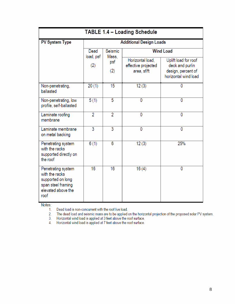
8

9
6.0 Mechanical System A. System Description
1. This provision is intended to provide direction on the decisions of the City in regards to mechanical systems. The criteria below give reference to specific code provisions described in the IMC. The adjacency of mechanical roof penetrations and clearances to the Solar PV systems can be critical to the provisions of IMC. Rooftop equipment in various building systems should be located in a manner that meets the requirements of the BOD. It is the intent of this section to establish alignment of the City installations with the IMC specific to Solar PV installations to ensure that the installation is in compliance with the building mechanical systems and to ensure that the building mechanical system is designed to accommodate a Solar PV system to the greatest extent possible.
B. Design Criteria
1. The building mechanical system, includes but is not limited to, exhaust and recirculation of air for building occupancy. The mechanical system regulated by IMC shall accommodate the ability to install Solar PV systems while meeting the provisions of the IMC. Other provisions of the IMC may apply as appropriate to the Solar PV design of the building. When installing the Solar PV systems described in section 3.0 above, care should be given to the requirements of the IMC.
a. Vent and Exhaust - Solar PV systems shall be designed, installed and maintained in a manner consistent with IMC sections 401.6, 501.2, 801.2, 908.3 and 1008.2. The vent and exhaust system discharge should not be placed in a location that would cause a nuisance to the Solar PV system (e. g. fuel burning appliance vent; vapor plumes; blow off valves; grease, hazardous dust, and other product conveying exhausts.)
b. Solar Systems – Other solar systems, equipment and appliances intended to utilize solar energy for space heating or cooling, domestic hot water heating, swimming pool heating or process heating are governed by IMC chapter 14 beginning with section 1401.1.
C. Coordination
1. The building mechanical system should be designed and installed in coordination with a potential Solar PV system as determined by the BOD. The building mechanical system should be designed to accommodate the Solar PV system in terms of its power capacity, location and ease of installation. The following items shall be included but not limited to:
General Services Department
Architecture & Engineering Division
Project Manager’s Manual
SCHEMATIC DESIGN PHASE
ISSUED DATE REFERENCE PERSON REVISION # REVISION DATE
9/1/2007 A&E Administrator ADA Update 11/29/2013
Revised Pages PAGE
2 & 3 ADA Related only Page 1 of 7
Schematic Design Rev 11-29-13 MD.doc Page 1 of 7 12/5/2013
SCHEMATIC DESIGN PHASE
The Architect/Design Consultant shall provide Schematic Design Documents based on the
mutually agreed-upon program, schedule, and budget for the Cost of the Work. The documents
shall establish the conceptual design (including options) of the Project illustrating the scale and
relationship of the Project components as well as options for systems and major components. The
design consultant will analyze each option and provide a recommendation to the City. The
Schematic Design Documents shall include a conceptual site plan, if appropriate, and preliminary
building plans, sections and elevations. At the Architect’s option (unless specified elsewhere),
the Schematic Design Documents may include study models, perspective sketches, electronic
modeling or combinations of these media. Preliminary selections of major building systems and
construction materials shall be noted on the drawings or described in writing. The Schematic
Design Documents shall include but shall not be limited to:
1. Overall Project Schedule including breakdown of major project activities. This includes but
is not limited to major construction activities (including any planned construction phasing),
project design phases with owner review cycles indicated. Construction manager to provide
the construction schedule for CM@R projects.
2. Construction cost estimate with breakdown by major construction disciplines (+/-20%
accuracy). Construction manager to provide the construction cost estimate for CM@R
projects. The design consultant is also expected to provide a cost estimate by major discipline
for comparison to the CM@R’s estimate.
3. Assist PM in developing/revising the overall project budget
4. Sitework (shown on site plans or in narrative form as appropriate and agreed to by the Project
Manager).
a. Paving, sidewalk, curb, fence, parking, and other site improvements.
b. Drainage, including a discussion of potential of the project to effect surrounding
properties (watershed), deterioration, detention / retention locations. A narrative
conceptualizing the drainage issues is expected. Plans to show conceptual
detention/retention pond sizes and locations.
c. Utility location site plans showing where utilities enter the site and the routing for
gas, water, electrical, telephone, sewer, cable, and data.

10
a. Mechanical equipment to be located on the roof should be installed in such a way to leave sufficient area for maintenance, access and a Solar PV array based on specifications determined in the BOD. Mechanical equipment includes but is not limited to: vents and exhaust systems, HVAC equipment, and any related conduit and piping for mechanical equipment (e.g. gas lines).
11
7.0 Electrical System A. System Description
1. This provision is intended to provide direction on the decisions of the City in regards to electrical systems. The criteria below give reference to specific code provisions described in the NEC. The use of electrical systems for the Solar PV systems can be critical to the long term viability of the electrical systems as well as life safety provisions of NEC. It is the intent of this section to establish alignment of the City installations with the NEC specific to Solar PV installations to ensure that the installation is in compliance with the building electrical systems and to ensure that the building electrical system is designed to accommodate a Solar PV system to the greatest extent possible.
B. Design Criteria
1. The building electrical system includes, but is not limited to, the main electric service as supplied by the utility, switchgear, transformers, branch circuits serving building loads, grounding, emergency or supplementary power systems, and the Solar PV system. The building electrical systems shall meet all provisions of the NEC. The building electrical system shall accommodate future Solar PV systems as described in the BOD, while meeting the provisions of the NEC for the building. When installing the Solar PV systems described in section 3.0 above, care should be given to the requirements of the NEC.
a. Solar Photovoltaic Systems - Solar PV systems shall be designed, installed and maintained in a manner consistent with NEC article 690.
C. Coordination
1. The building electrical system should be designed and installed in coordination with a future Solar PV system as determined by the BOD. The building electrical system should be designed to accommodate the Solar PV system to the greatest extent possible in terms of its power capacity, location and ease of installation. The following items shall be included but not limited to:

12
a. Capacity and ability of the electric service to accommodate the power generated by a Solar PV system as determined by the BOD so that it can be interconnected with the building system. (A location within the main disconnect panel for a dedicated Solar PV circuit breaker should be labeled as “Future Circuit Breaker From PV System” and left vacant. This breaker position must be located at the opposite end of the panel from the main utility breaker.) This circuit breaker location should allow for a 240-volt breaker.
b. Sufficient space allocated for Solar PV equipment such as the inverter, disconnects, metering, etc. as determined by the BOD (interior or exterior locations may be considered).
c. To facilitate wiring, consider adding conduit and/or stub-ups to the roof and terminating at the location of the Solar PV array. The size and number of conduits will be determined by the BOD.
d. Electrical equipment to be located on the roof should be installed in such a way to leave sufficient unshaded area for a Solar PV array based on specifications determined in the BOD. Electrical equipment includes but is not limited to: electrical conduit, lightning protection cables, bird deterrent devices, or any other items requiring wiring.
e. To minimize electrical losses associated with the transmission of DC energy, the distance between the Solar PV array and the inverter should be minimized to the greatest extent possible.
f. Any pre-installed components should be properly labeled to ensure that a Solar PV system will take advantage of the accommodations that were made (such as circuit breaker location, conduit or stub-ups installed with pre-determined wire sizes, conduit fill capacities, Solar PV system output limitations at main service panel if known, etc.)

13
8.0 ADOSH (Arizona Department of Occupational Safety and Health)
A. System Description
1. It is the intent of this section to establish alignment of the City installations with the ADOSH specific to Solar PV installations to ensure that the installation is in compliance with ADOSH and to ensure that the worker access system is designed to accommodate a Solar PV system to the greatest extent possible.
B. Design Criteria
1. When designing, installing and maintaining the Solar PV systems described in section 3.0 above, care should be given to the requirements of ADOSH, including:.
a. 29 CFR part 1910 subpart D contains requirements specific to walking-working surfaces safety.
b. 29 CFR part 1910 Subpart E contains requirements for means of egress safety.
c. 29 CFR part 1910 Subpart S contains requirements for electrical safety.
d. 29 CFR part 1926 Subpart K contains requirements for electrical safety.
e. 29 CFR part 1926 Subpart M contains requirements for fall protection safety.
f. 29 CFR part 1926 Subpart X contains requirements for ladder safety.
C. Coordination
1. ADOSH compliance should include but not be limited to:
a. The design of the roof, exterior fenestration for window washing, should consider the location and extent of the Solar PV system as determined by the BOD.
b. The design of the access to the roof to accommodate the workers for maintenance of roof top equipment should consider the location and extent of the Solar PV system as determined by the BOD.
14
9.0 Fire Department Access A. Description
1. This provision is intended to provide direction on the decisions of the City in regards to fire department access. The criterion below gives reference to specific code provision described in the IFC. The access to roofs during a fire event can be critical to the long term viability of the building as well as the safety of the occupants within. It is intent of this section to establish alignment of the City installations with the IFC specific to Solar PV installations to ensure that the installation is in compliance with the fire department access systems and to ensure that the fire department access systems are designed to accommodate a Solar PV system to the greatest extent possible.
B. Criteria
1. The building fire system requirements address but are not limited to access to roofs, electrical systems and building occupancy. The fire department access design regulated by IFC shall accommodate the ability to install Solar PV systems while meeting the provisions of the IFC. Other provisions of the IFC may apply as appropriate to the Solar PV design of the building. When installing the Solar PV systems described in section 3.0 above, care should be given to the requirements of the IFC.
a. Access to Roofs - Solar PV systems shall be designed, installed and maintained in a manner consistent with IFC Section 504.
b. Electrical - Solar PV systems shall be designed, installed and maintained in a manner consistent with IFC Section 605.
C. Coordination
1. The fire department access system should be designed and installed in coordination with a future Solar PV system as determined by the BOD. The fire department access system should be designed to accommodate the Solar PV system to the greatest extent possible in terms of its power capacity, location and ease of installation. The following items shall be included but not limited to:
a. The BOD should provide designs that comply with access requirements and edge restrictions contained in IFC 2012.
b. The site design for fire truck access and accommodating hose connections from hydrant to fire truck to fire nozzles should consider location and extent of the ground mounted Solar PV system as determined by the BOD.

15
c. The site design for outdoor safe dispersal areas to meet IBC section 1024.6 and accommodating exit routes from exterior doors to the public ways should consider the location and extent of any ground mounted Solar PV system as determined by the BOD.
d. The design of the electrical panel system and fire department access to de-energize during a fire event per NEC Article 690.14 should consider the size and electrical demands of the Solar PV system as determined by the BOD.
16
10.0 Quality Assurance/Review A. Description
1. The completion of the design of the buildings incorporating the impact of Solar PV systems upon the building is achieved through a series of incremental design and construction milestones. The BOD shall be completed at the Schematic Design phase of the building design so that Solar PV systems type, location, and cost can be established, decreasing the need for rework in the design documents. The BOD shall describe the Solar systems (in the present design and future) for the building in a graphic representation of site plan, floor plans and sections. A written narrative shall accompany and support the graphic form.
17
11.0 References A. City of Tucson, Solar Integration Plan, March 2009 – Plan laying groundwork for
accelerating development of solar energy facilities in and around Tucson. http://www.tucsonaz.gov/energy/Solar%20Plan%20Final.pdf
B. Solar America Cities, Solar Powering Your Community: A Guide for Local Governments, January 2011 – A guidebook with examples to stimulate ideas for a comprehensive solar plan for communities. http://solaramericacommunities.energy.gov/resources/guide_for_local_governments/
C. John Wiles, Southwest Technology Development Institute (SWTDI), Recommendations for Building Solar Ready Buildings Photovoltaic Systems, 23 June 2009. Attached as Appendix A below
D. L.Lisell, T Tetreault and A Watson, Solar Ready Buildings Planning Guide, NREL Technical Report NREL/TP-7A2-46078, December 2009

18
12.0 Appendices
Appendix A - Recommendations for Building Solar Ready Buildings Photovoltaic Systems, John Wiles, Southwest Technology Development Institute (SWTDI). June 23, 2009 Appendix B - Structural Calculations

19
Appendix A – Recommendations for Building Solar Ready Buildings Photovoltaic Systems
General Services Department
Architecture & Engineering Division
Project Manager’s Manual
SCHEMATIC DESIGN PHASE
ISSUED DATE REFERENCE PERSON REVISION # REVISION DATE
9/1/2007 A&E Administrator ADA Update 11/29/2013
Revised Pages PAGE
2 & 3 ADA Related only Page 2 of 7
Schematic Design Rev 11-29-13 MD.doc Page 2 of 7 12/5/2013
d. Initiate and document contact with City of Tucson Zoning and Planning to obtain
preliminary requirements.
e. Landscape concept.
f. Cultural Resources - Per Administrative Directives from the City Manager’s office, a
cultural resource review is required for all Capital Projects. This review is to occur
prior to the design of any building projects requiring excavations of any kind. There
is a Cultural Resource Clearance request form that needs to be filled out, go to
(http://intranet/ad/1-07-7.pdf). Also, you may call the City of Tucson Dept. of Urban
Planning and Design; 520-791-4505 for any assistance you may need. The City’s PM
is responsible for ensuring the Cultural Resources Review is completed. The design
consultant is expected to report on the results and their potential project impacts in
the SD report.
g. Surrounding Neighborhood – Consider the use of the proposed facility and the
possible impact the facility may have on the immediate neighborhood from such
changes as increased noise, increased traffic, and other quality of life impacts.
h. Survey - Verify and document property easements and constraints. Note any
potential problems. The City’s PM is responsible for ensuring the survey is
completed by the Architect/Consultant or by others. TEP:(transformer location) get
legal description and show on survey if there is an existing transformer and electric
service easement. Note new service easement is typically provided during
construction and should go through City Real Estate Department to obtain the TEP
easement. City’s PM is to ensure survey is performed to our requirements. The
survey may be under the design consultant’s scope or by others.
i. Water Harvesting - Provide a narrative description as to how the project will meet
the Tucson code requirements for water harvesting as described in Appendix A of
the City of Tucson Water Harvesting Manual, which is available at
http://www.dot.ci.tucson.az.us/stormwater/downloads/2006WaterHarvesting.pdf .
Consultant is also to provide a cost/benefit analysis of additional water harvesting
opportunities. The cost/benefit analysis is not intended to be a detailed study but
should provide enough information for the City to make informed decisions whether
or not to pursue further water harvesting opportunities on the project.
j. Accessible parking and route.
5. Code Analysis
ACCESSIBILITY – Americans with Disabilities Act (ADA)
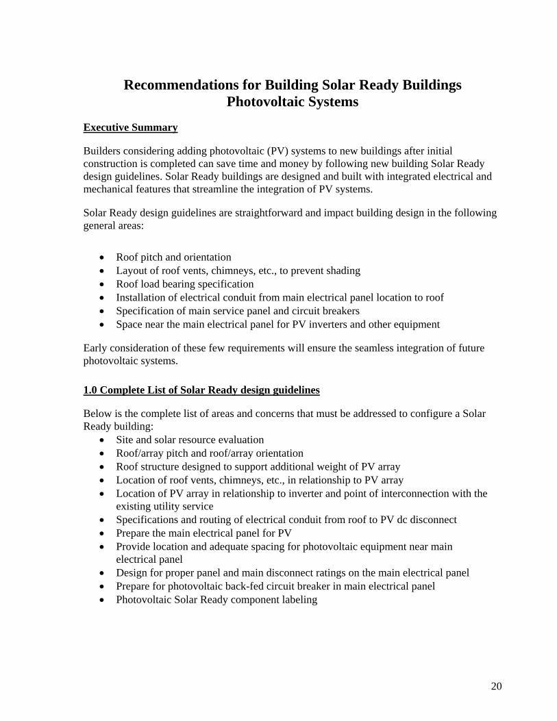
20
Recommendations for Building Solar Ready Buildings Photovoltaic Systems
Executive Summary
Builders considering adding photovoltaic (PV) systems to new buildings after initial construction is completed can save time and money by following new building Solar Ready design guidelines. Solar Ready buildings are designed and built with integrated electrical and mechanical features that streamline the integration of PV systems.
Solar Ready design guidelines are straightforward and impact building design in the following general areas:
• Roof pitch and orientation • Layout of roof vents, chimneys, etc., to prevent shading • Roof load bearing specification • Installation of electrical conduit from main electrical panel location to roof • Specification of main service panel and circuit breakers • Space near the main electrical panel for PV inverters and other equipment
Early consideration of these few requirements will ensure the seamless integration of future photovoltaic systems.
1.0 Complete List of Solar Ready design guidelines
Below is the complete list of areas and concerns that must be addressed to configure a Solar Ready building:
• Site and solar resource evaluation • Roof/array pitch and roof/array orientation • Roof structure designed to support additional weight of PV array • Location of roof vents, chimneys, etc., in relationship to PV array • Location of PV array in relationship to inverter and point of interconnection with the existing utility service • Specifications and routing of electrical conduit from roof to PV dc disconnect • Prepare the main electrical panel for PV • Provide location and adequate spacing for photovoltaic equipment near main electrical panel • Design for proper panel and main disconnect ratings on the main electrical panel • Prepare for photovoltaic back-fed circuit breaker in main electrical panel • Photovoltaic Solar Ready component labeling
21
The following sections describe each of these requirements in detail. This information is intended as a guide in cases where the PV system design has not been determined. In cases where the design of the future PV system is already known, some of these recommendations can be changed to more specifically and effectively accommodate the system installation. For example, when the type and model of PV modules are known, specific direct current (dc) wiring and disconnects can be sized and installed in advance.
2.0 Descriptions of recommended design guidelines
2.1 Site and solar resource evaluation:
When designing a PV Solar Ready building, a basic design requirement will be to perform a site evaluation of the building's location and orientation to the existing solar resource. This evaluation should take into account the relationship of the building to the path of the sun throughout the year. The location of any existing (or future) foliage that may shade the photovoltaic array should also be considered. It is recommended that the building's landscape design avoid tall trees and other objects that may eventually cast a shadow on the photovoltaic array. Areas to the east, south, and west of the building should be carefully landscaped to avoid shading the array during the corresponding portions of the day.
2.2 Roof/array pitch and roof/array orientation:
Another basic design requirement will be to determine the pitch and orientation of both the roof and the photovoltaic array. The roof surface where the PV array is to be located will, in an ideal case, be oriented directly toward the solar resource. This is generally to the south in the northern hemisphere. Where possible, the pitch of the roof plus the tilt of the array should be slightly less than or equal to the local latitude to provide optimal year round performance.
2.3 Roof structure designed to support additional weight of PV array:
When building a Photovoltaic Solar Ready building, the structural integrity of the roof should be examined to determine that it will carry the added weight of the photovoltaic system and the mounting components. The additional weight of the system will vary greatly depending upon the photovoltaic modules and mounting system used. In general, the roof below the photovoltaic array should be designed to support at least an additional 5 lbs/sq ft of dead weight.
22
2.4 Location of roof, vents, chimneys, etc., in relationship to PV array:
When designing the layout and location of roof protrusions, special consideration should be given to the location of roof vents, chimneys, gables, or other obstructions that could cast shadows upon the photovoltaic array. The roof design should allow ample clearance for the anticipated photovoltaic array as well as eliminate any shading obstructions along the projected solar path. In general, in the northern hemisphere, any roof protrusions should be located to the north of the planned array location and, depending upon the orientation of the roof surface, other protrusions should be limited to those locations that will limit the amount of shading during the year.
2.5 Location of PV array in relationship to inverter and point of interconnection:
To minimize losses associated with the transmission of dc energy, the distance between PV array output and the inverter should be kept to a minimum. For instance, if the inverter and main electrical panel are to be located in a garage or utility room, a logical location for the PV array would be on the appropriate roof surface directly above the garage or utility room location. This also serves to minimize the amount of electrical supplies, conduit, wire, etc., necessary to complete the connection between the PV array and the inverter.
2.6 Specifications and routing of de conduit from roof to de disconnect location:
A metal conduit is necessary to bring the dc wiring from the PV array output to the location of the dc combiner panel or dc disconnect (depending on the design of the PV system). The size of this conduit should be no smaller than 1" to accommodate the dc wiring.
If the building has an accessible attic space, it is recommended that the conduit be terminated within the attic area to allow for future installation flexibility. The installer will then route the conduit through the attic to the appropriate location before penetrating the roof surface. If the attic is inaccessible, the conduit penetration should be located in a place on the roof as near the anticipated PV array output as possible to minimize the amount of exposed wiring between the PV modules and the input to the conduit.
If the building has a flat roof the dc wiring conduit can be terminated on the inside of a parapet wall or, if necessary, up through the ceiling and roof surface at the appropriate location.
The opposite end of this conduit should be in a location where it can be easily connected to any future component: dc disconnect, dc combiner. Both ends of the conduit should be capped off to keep out water and pests.
2.7 Location and adequate spacing for photovoltaic equipment near main electrical panel:

23
Adequate space should be available in a readily accessible location for a dc disconnect, inverter, ac disconnect and, if applicable, PV system renewable energy credit (REC) meter and utility required ac disconnect will be mounted. The dimensions required for the location for the PV equipment will largely depend upon the PV system design and equipment choices. In general, a commercial PV system consisting of the equipment mentioned above will require four to five horizontal feet of wall space with adequate clearance above and below the mounting locations. The requirement and location for an additional ac disconnect and PV REC meter is determined by the requirements of the local jurisdiction as well as the local electric company. If this equipment must be located within site of the main electrical disconnect on the exterior of the building, it is recommended that the building design allow two to three feet of space.
2.8 Design for proper bus bar and main disconnect ratings on the main service panel:
The National Electrical Code (NEC) imposes requirements on the size of a PV system that can be added to a specified size of existing electrical service.
The 2005 NEC requires that commercial installations meet the requirements of section 690.64 which covers the point of connection and allows for two types of photo voltaic system interconnection. Section 690.64 (A) allows the output of a photovoltaic power source to be connected to the supply side of the service disconnect. This is often the best option for photovoltaic system retrofits on commercial buildings.
The second option described in section 690.64 (B) is the load side connection. This option requires that the sum of the photovoltaic breaker and the main breaker is less than or equal to the rating of the distribution panel. In the case where the building is constructed with a photovoltaic system in mind, it will be necessary to size the distribution panel, main breaker and photovoltaic breaker appropriately. In the case of series connected panels, the main breaker for each panel is counted in the above calculation.
For instance, an 800-amp main circuit breaker rating along with a 1000-amp panel rating will accommodate up to 200 amps of ac current, which would allow PV systems up to 60 kW in size on a 3 phase 208 Volt service.
In the case of series connected panels, if a 20-amp PV breaker feeds into a 100-amp panel with an 80-amp main then the 80-amp breaker is used to calculate the size of the main breaker in the main panel.
The 2008 NEC Section 690.63 allows commercial buildings to install breakers that when added to the main breaker are less than or equal to 120% of the rating of the distribution panel. The photo voltaic breaker must be installed in the location of the panel farthest from the utility breaker. Also Section 690.63 in the 2008 NEC states that only the PV breaker is counted in the case of series connected panels.
For instance, a 1000-amp main circuit breaker rating along with a 1000-amp panel rating will accommodate up to 200 amps of ac current, which would allow PV systems up to 60 kW in size on a 3 phase 208 Volt service. If the future photovoltaic system will produce more than
24
20% of the main circuit breaker's rating, then the size of the main electrical panel should be increased, in accordance with NEC 690.64(B).
2.9 Considerations for photovoltaic circuit breaker in main disconnect panel:
If the size of the PV system is unknown, a location (within the main disconnect panel) for the circuit breaker should be labeled as "Future Circuit Breaker From PV System" and left vacant for the installer to specify and connect. This breaker position must be located at the opposite end of the panel from the main utility breaker. This circuit breaker location should allow for a 240-volt breaker which, in turn, will allow the option of a 120-volt system to be installed if this is desired.
2.10 Photovoltaic Solar Ready component labeling:
Proper labeling of the pre-installed components will ensure that a future PV system installation will properly take advantage of the various features of the Solar Ready building. A label detailing specific PV system output limitations is recommended for the main service panel. This label should detail the current limitations and voltage level required to meet the various electrical standards, NEC, and local requirements. The PV circuit breaker location should also be labeled as such. It is also recommended that the dc conduit be labeled with appropriate wire size ranges and conduit fill capacities briefly detailed as well.
Prepared by staff of the Southwest Technology Development Institute, New Mexico State University, Las Cruces, NM, June 23, 2009

25
Appendix B – Structural Calculations
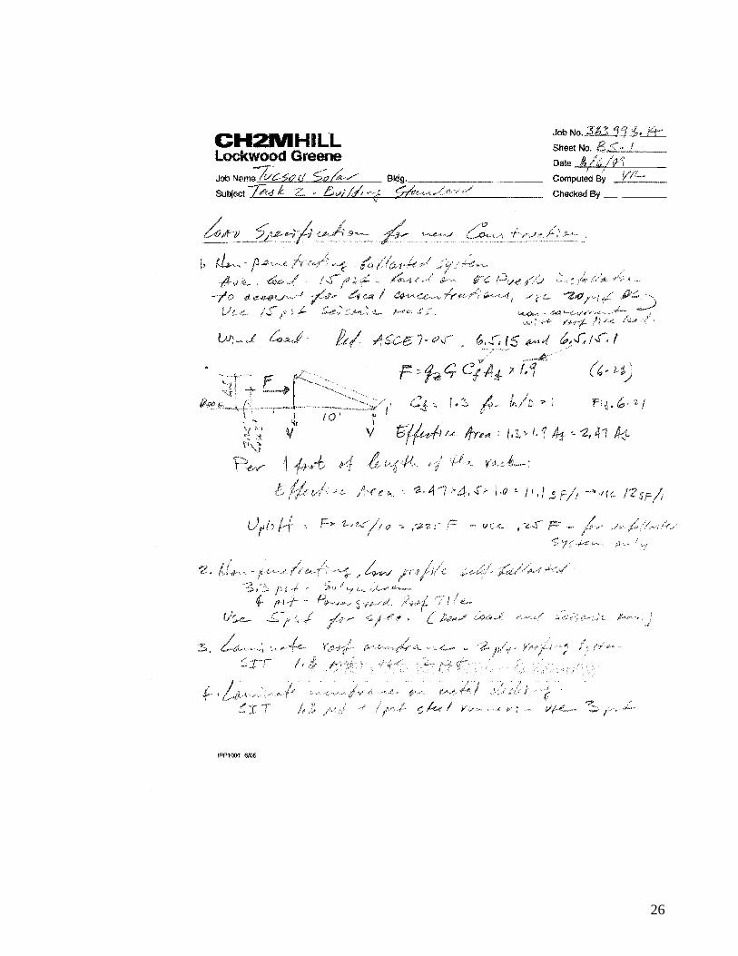
26
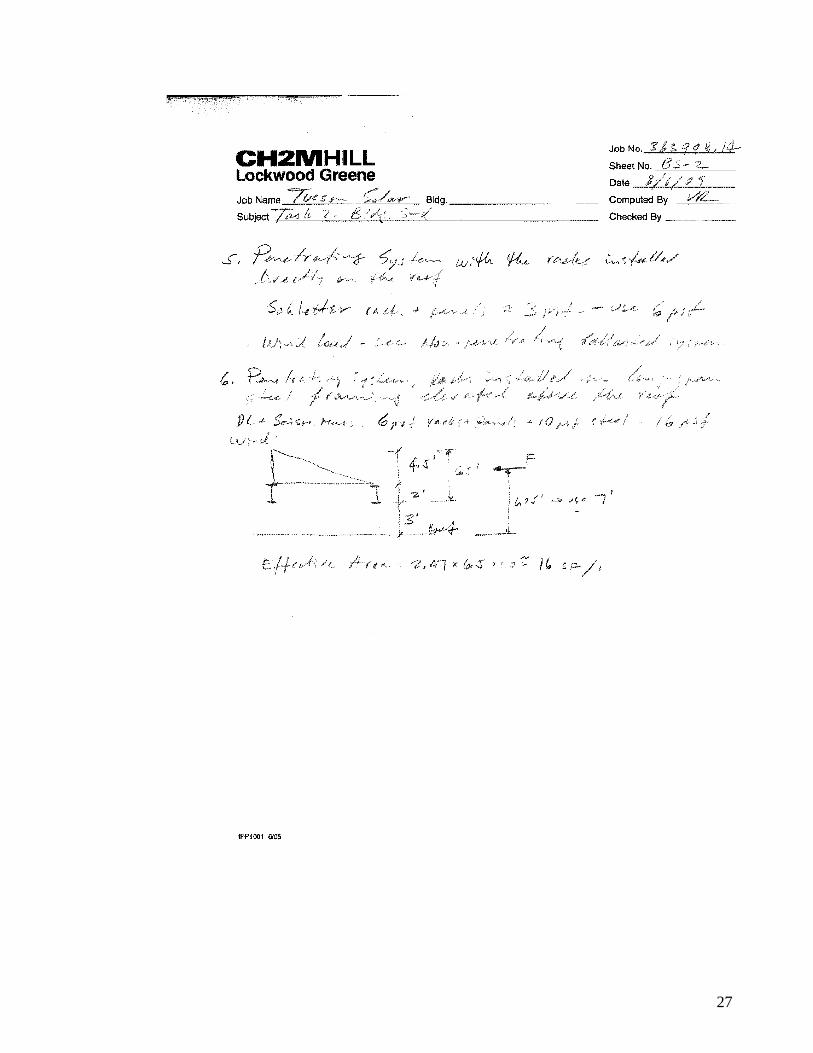
27

City of Tucson
General Services Department Architecture and Engineering Division
“AUTOCAD STANDARDS
AND GUIDELINES”
Revised: September 2, 2008
City of Tucson Architecture and Engineering AutoCAD Standards and Guidelines ▀▀▀▀▀▀▀▀▀▀▀▀▀▀▀▀▀▀▀▀▀▀▀▀▀▀▀▀▀▀▀▀▀▀▀▀▀▀▀▀▀▀▀▀▀▀▀▀▀▀▀▀▀▀▀▀▀▀▀▀▀▀▀▀▀▀▀▀▀▀▀▀▀▀ September 2, 2008 page -2
INTRODUCTION This notebook is a specification and reference to the City of Tucson, General Services Department, Architecture & Engineering Division’s (AED) use of AutoCAD. The specifications describe the standards and procedures for input of drawings into a format acceptable to the AED. Compliance is required where called for in contractual agreements for providing electronic “as-built” ACAD and PDF files to the AED. Only AutoCAD 2006 or later will be accepted. PDF’s may be any version of Adobe Acrobat (2000 or later is recommended). This notebook is a living document. As the division's use of CAD matures and technology advances this notebook changes reflecting the progress. Updated sections are issued frequently. Please direct any comments you may have regarding these AutoCAD Standards to Octavio A. SantaMaria, Jr. (520) 791-5111 x 331 or e-mail [email protected] .