architectural portfolio
DESCRIPTION
Compilation of architectural design work through first semester graduate school.TRANSCRIPT

Jason Hudson Portfolio 3/08/15

1
246
101620262834
---------
Table of ContentsEssay - Reflection
Twist & StretchFolding the BlockGreen Link to the FutureBicycle HighwayEssay - Grad StatementParametric PavilionConcord Cultural Hub
“Dream City” Armature
2Essay - Reflection
Feb 2015Reflection
3
I distinctly remember the first Christmas I tried to compile a wish list. I was maybe 7 years old, still believed in Santa, and was convinced that as long as I could conceive of a thing, it could be created in his magical workshop. I won’t pretend to remember the name of any item I requested, but to properly set the scene for you, they were items such as the “Singing Pink Flamingo 3000,” “Island Racing Fire Bear,” or the “Extreme-o Star Warrior Battle Cruiser.” I was a strange kid (but that’s not the point of this story). The point is none of the items on that list were actually real toys. To their credit, my parents readily came up with a plausible explanation for why the things I asked for actually had to exist, and furthermore be readily available for purchase at a nearby store. Thus my innocence was preserved and I continued to believe in Santa for many more years.
It’s kind of a stupid memory, one that I’ve held on to for no real good reason. It only recently occurred to me, if not in a moment of clarity, then in a moment of “why the heck not,” that this memory could be relevant to the process of looking back on my work and compiling it in a portfolio. While I am putting this together to show and communicate my skills to others, the portfolio process does me good in that it is a chance for me to reflect on the work that I’ve done and pull the pieces together not as I would have five or so years ago, but as I would today with the kind of critical lens that only comes with hindsight. Similarly, looking back as an adult on that silly Christmas memory, I can see now that 7-year-old me had planted the seed of a set of ideas and questions that I now ask myself as a designer - If I can conceive of something… can I make it? Should I? And how? Do the things I envision and make need to be made of pieces that are readily purchasable at a nearby store? Should the buildings themselves come off a shelf or out of a catalog, so to speak? Or can I invent the pieces myself?
The thing I find most appealing about architecture is that there is the potential to create something unique that didn’t exist before and watch it blossom from a sketchy thought to a physical construction. And while like in many creative endeavors there is in architecture the potential for infinite creativity, due to its scale, lifespan, cost, and its prominence in the lives of its users, architecture is limited by the laws of physics, concerns for durability, economic feasibility, and the whims not of its designer –but of its users, in a way unlike any other creative art. One of the major defining forces that shapes a building’s construction is the balance between infinite creativity and what is feasible. In a way, that balance is analogous to the wishful imagination of a seven year old versus the necessary practicality of his parents.
Since I first started this catalog of work as a freshman at Clemson University, my architectural knowledge has increased greatly and the way I go about designing a project has changed drastically. Since my first portfolio revision, my idea of which projects to include and what I say about them has evolved. Each project, though, is a critical piece in my development as an architect. So I’ve chosen to include a cross section of the work back to my freshman year and in this process of selection and exposition, highlight the qualities that evolve throughout my body of work that have come to define me as a designer. Through this process I have gained a better understanding of my abilities, and I hope you will understand me better by browsing through.
Thanks for reading, and enjoy!
-Jason Hudson

4“Dream City” Armature
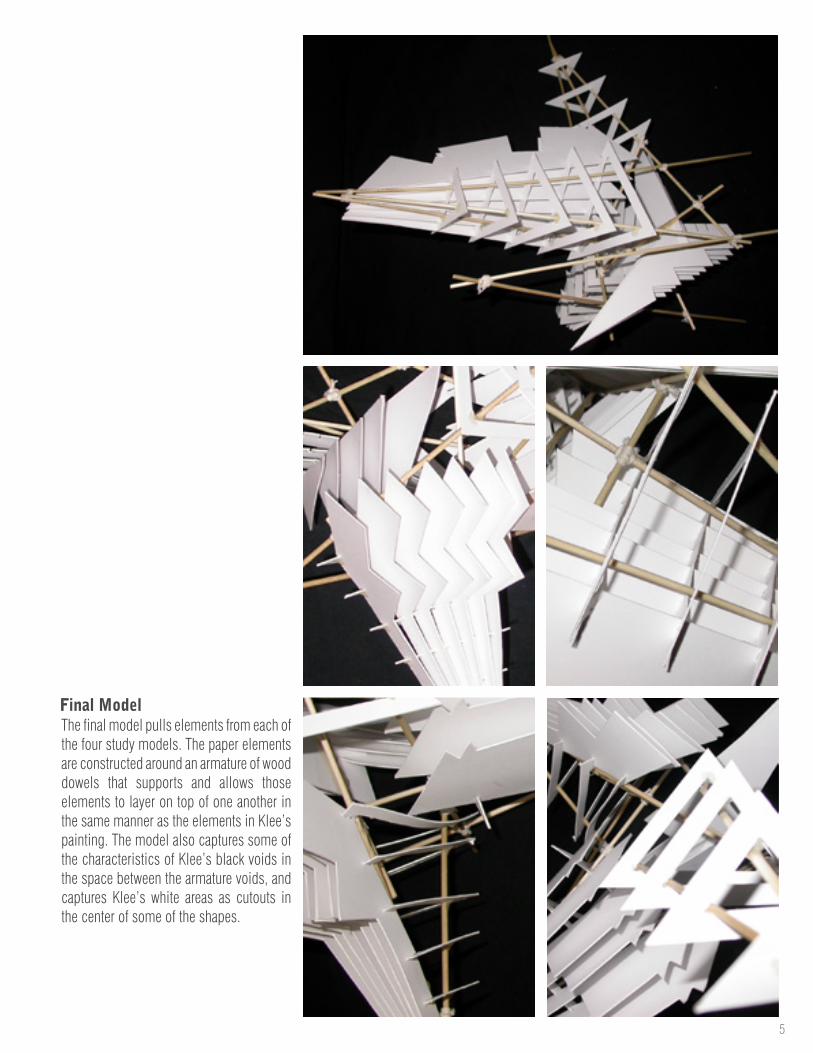
This project was a simple exercise in model building inspired by source material. The painting below is a Paul Klee painting called “Dream City.” A series of physical study models (left) were built to emulate the characteristics of the painting. A final model was then constructed based on the explorations done in the study models. I did not include this project in the previous iteration of my portfolio, but lately I’ve been concerned with the process of architecture and how the process manifests itself in a completed design, so I felt it was fitting to include it now.
Project Background
Fall 2007Freshman
Harry HarritosClemson
N/A
-----
“Dream City” ArmatureSemesterClass YearProfessorSchoolProject Location
5
Final ModelThe final model pulls elements from each of the four study models. The paper elements are constructed around an armature of wood dowels that supports and allows those elements to layer on top of one another in the same manner as the elements in Klee’s painting. The model also captures some of the characteristics of Klee’s black voids in the space between the armature voids, and captures Klee’s white areas as cutouts in the center of some of the shapes.

6Twist & Stretch
Project Background
Fall 2008SophomoreJori Erdman
ClemsonLee Hall, Clemson, SC
-----
Twist & Stretch - Foot BridgeSemesterClass YearProfessorSchoolProject Location
I chose a word - “stretch” - that would be used to inform my design. The word fits perfectly with the concept of a bridge - pull the ends of an object apart, the resulting form is a passage between two points. I used a piece of silly putty to demonstrate that action.
Concept
The objective for this project was to design a bridge that would span across the outdoor courtyard located in Lee Hall, Clemson University’s building for the School of Architecture.
7
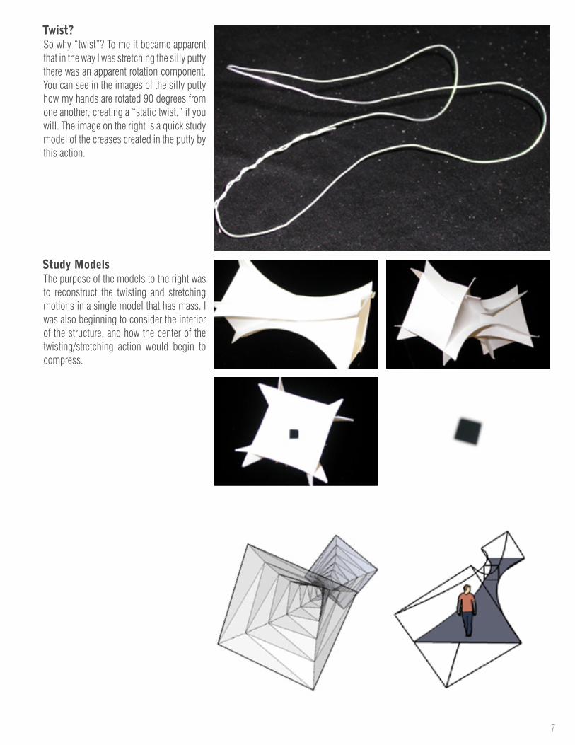
The purpose of the models to the right was to reconstruct the twisting and stretching motions in a single model that has mass. I was also beginning to consider the interior of the structure, and how the center of the twisting/stretching action would begin to compress.
Study Models
So why “twist”? To me it became apparent that in the way I was stretching the silly putty there was an apparent rotation component. You can see in the images of the silly putty how my hands are rotated 90 degrees from one another, creating a “static twist,” if you will. The image on the right is a quick study model of the creases created in the putty by this action.
Twist?

8Twist & Stretch
Courtyard Below
Aerial ViewThe bridge eventually took on the form shown to the left. Two masses taper towards the center of the bridge with roof slats and structural members that are space in a way so as to reinforce the “stretching” motion. The understructure of the bridge and the tilted roofs add the “twisting” element.

9
Physical Model
View inside the Bridge
Looking back on this project now, I can appreciate the way the form of this project was influenced by iteration in each step - from the conceptual stretching of silly putty to a physical, architectural model. I think perhaps some of the uniqueness of the silly putty shape got lost along the way, and my final result would almost surely be different if I did this project today, but looking back I was able to find some similarities here to the way I work now in how there was a central concept that could be traced through each successive step towards the final result.
10Folding the Block
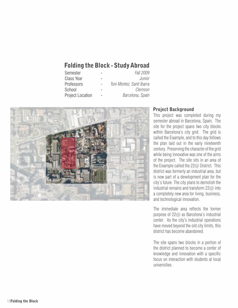
This project was completed during my semester abroad in Barcelona, Spain. The site for the project spans two city blocks within Barcelona’s city grid. The grid is called the Eixample, and to this day follows the plan laid out in the early nineteenth century. Preserving the character of the grid while being innovative was one of the aims of the project. The site sits in an area of the Eixample called the 22@ District. This district was formerly an industrial area, but is now part of a development plan for the city’s future. The city plans to demolish the industrial remains and transform 22@ into a completely new area for living, business, and technological innovation.
Project Background
Fall 2009Junior
Toni Montez, Santi IbarraClemson
Barcelona, Spain
-----
Folding the Block - Study AbroadSemesterClass YearProfessorsSchoolProject Location
The immediate area reflects the former purpose of 22@ as Barcelona’s industrial center. As the city’s industrial operations have moved beyond the old city limits, this district has become abandoned.
The site spans two blocks in a portion of the district planned to become a center of knowledge and innovation with a specific focus on interaction with students at local universities.

11
By pushing, pulling, and lifting the perimeter at strategic intervals, deviations from the typical Eixample block perimeter are created. The end result takes the form of a folded plane that binds the continuous perimeter of the block together. By manipulating the plane, pedestrian activity from the street can be made to extend to the center of the block through the perimeter.
ConceptThis project explores the relationship of the city street to the center of the block. It looks to create interaction between the two areas by manipulating open spaces at the perimeter of the block.
The perimeter is thought of as an object that can be pushed back to reach the center of the block. In doing so, open space is extended from the street to the interior.
12Folding the Block
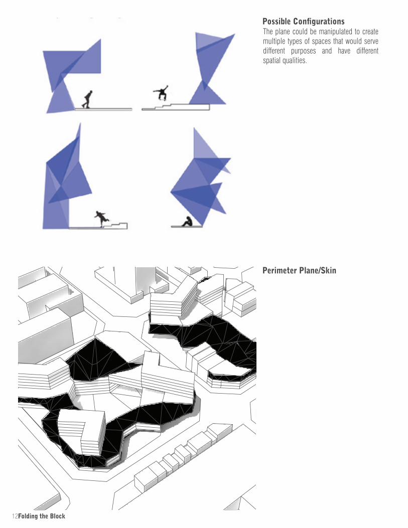
Possible ConfigurationsThe plane could be manipulated to create multiple types of spaces that would serve different purposes and have different spatial qualities.
Perimeter Plane/Skin
13
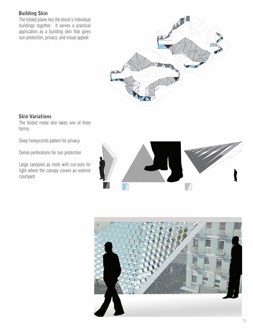
The folded metal skin takes one of three forms:
Deep honeycomb pattern for privacy
Dense perforations for sun protection
Large canopies as roofs with cut-outs for light where the canopy covers an exterior courtyard
Skin Variations
Building SkinThe folded plane ties the block’s individual buildings together. It serves a practical application as a building skin that gives sun protection, privacy, and visual appeal.
14Folding the Block
Academic
Retail
Warehouse
Public Office
Private Office
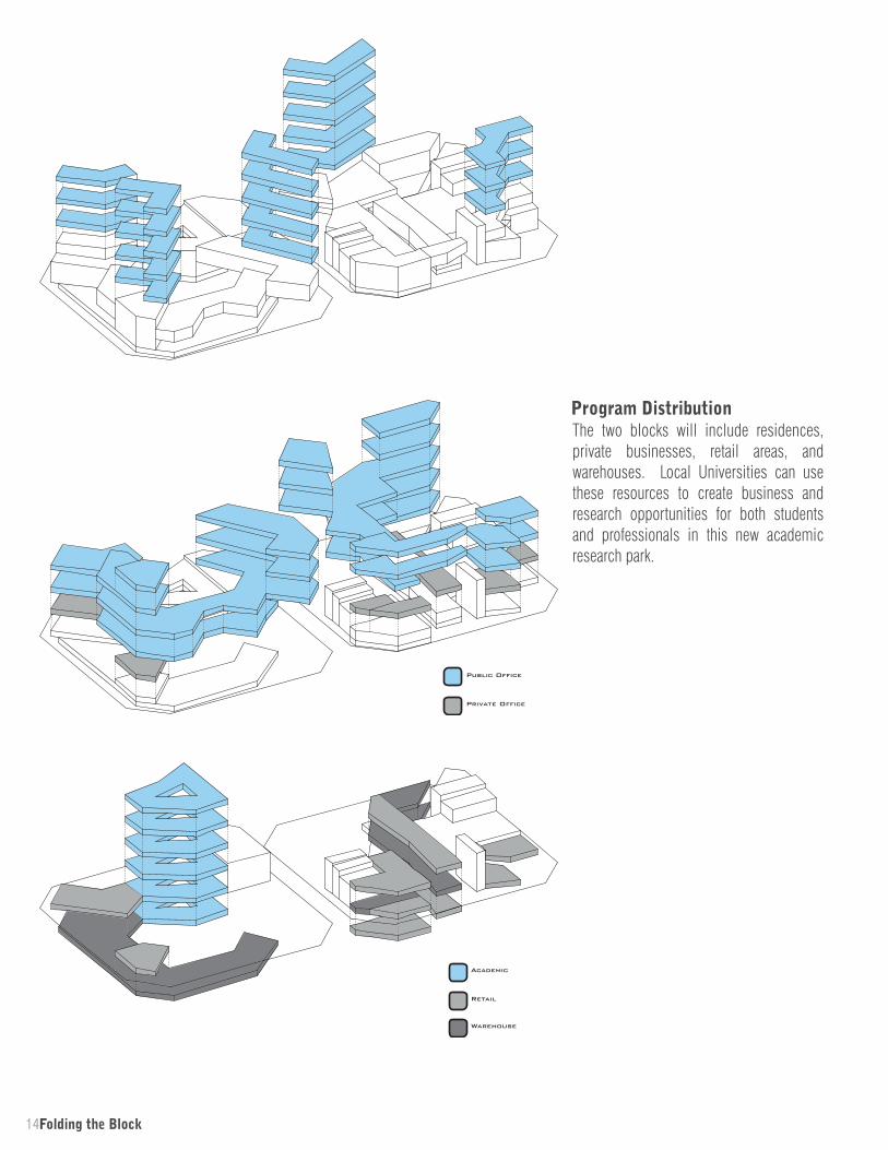
Program DistributionThe two blocks will include residences, private businesses, retail areas, and warehouses. Local Universities can use these resources to create business and research opportunities for both students and professionals in this new academic research park.

15
Perspective - Block Interior
Perspective
Section

16Green Link to the Future
Project BackgroundAnderson University recently purchased a new tract of land that it plans to develop into a dedicated area for the school’s various athletic programs. Located several blocks east from the main campus, the new land roughly doubles the current campus’s size and gives the land-locked campus great potential for growth. Located directly northeast of the new area is a previously purchased but undeveloped area that is ideal for studying ecology and biology, where the university also plans to add research buildings. The first step of the project was a group task of creating a master plan for the new campus. Our plan centered around creating connections that would benefit the university now and in the future with respect for the university’s history. The project focuses first on making connections between its three distinct parts, the campus and community. The vehicle we chose to do this with was using the natural environment as a connector - a major artery of greenscape would connect the three areas of campus and tie the site together. We would also add areas on the athletic campus that the community could take advantage of - the additional beautification by means of the greenscape would further serve to make it a desirable place for the community.
Spring 2010Junior
Harry HarritosClemson
Anderson, SC
-----
Green Link to the FutureSemesterClass YearProfessorSchoolProject Location

17
Final Model
This project was developed mostly with physical models. Each iteration further developed a distinct form for the facade and articulated connections between the man disparate elements.
Study Models
After the brief master planning stage, the individual group members chose one building on the master plan and developed it further. I chose to develop the soccer stadium located in the western half of the site.
Echoing our master plan’s theme of transitioning from and unifying separate campuses, my plan for the building was about unifying an angular, vertical, machined facade with the horizontal organic stadium surface.
Athletic Stadium
18
Locker Room
Classrooms/Activity Rooms
Tickets
Indoor Seatingand Lounge
Cafe
Trophy Room/Exhibition Space
Soccer/Football Field
Green Link to the Future
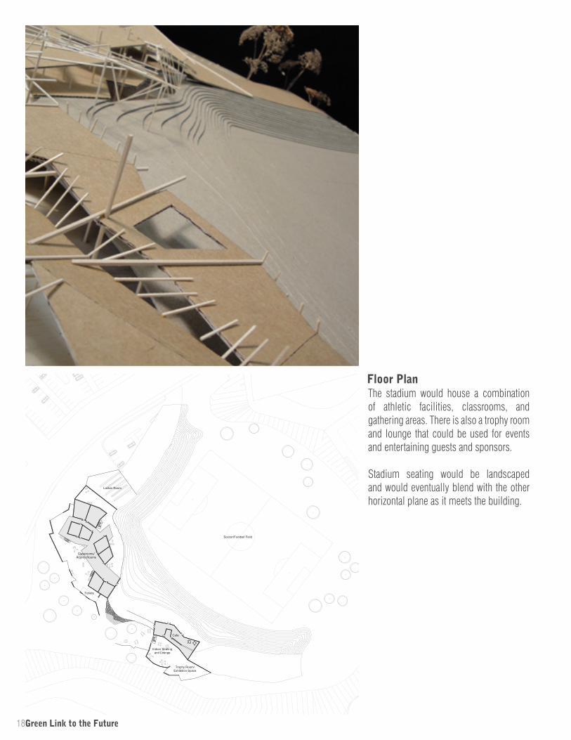
The stadium would house a combination of athletic facilities, classrooms, and gathering areas. There is also a trophy room and lounge that could be used for events and entertaining guests and sponsors.
Stadium seating would be landscaped and would eventually blend with the other horizontal plane as it meets the building.
Floor Plan
19
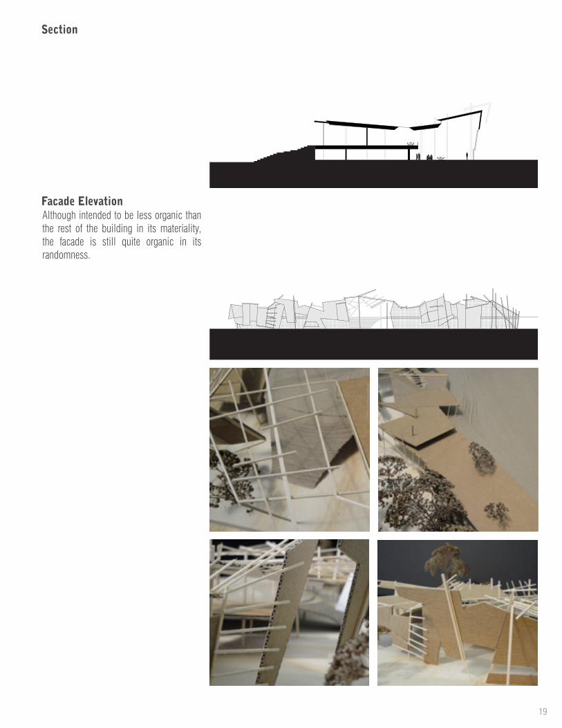
Section
Facade ElevationAlthough intended to be less organic than the rest of the building in its materiality, the facade is still quite organic in its randomness.

20Bicycle Highway
Bicycle Highway is a project that would be located on the Swamp Rabbit Trail in Greenville, South Carolina. The Swamp Rabbit Trail is a recreational bike and foot path that extends from downtown Greenville to the nearby town of Traveler’s Rest. There are plans to extend branches of the trail to other nearby cities. The intent of this project was to design a hub, located where the trail meets downtown Greenville, that would serve the trails users by providing them with access to food, water, bike supplies, repairs, etc. in a centralized location conveniently located adjacent to the trail.
Project Background
Fall 2010Senior
Kevin HyslopClemson
Greenville, SC
-----
Bicycle HighwaySemesterClass YearProfessorSchoolLocation

21
Restrooms/Showers
Information
Gathering Area
Cafe Seating
CafeWater
Vending
Tire Re�ll
Maps
Rentals
Retail
Bike Sales
Conference Room
Lounge
Daily Bike Storage
Bike Rack
First Aid
DRIVE UPDRIVE THRU
DRIVE IN
My concept for the project was to create three distinct building sections housing different functions categorized by the degree to which they interact with the trail. Inspired by automobile culture and the specialized building types that have grown up around it, the three sections are:
1) Drive Thru - where users would stop for a second or two to refill water or grab a quick snack from a vending machine.2) Drive Up - where users would stop for more than a moment, engage the building more fully i.e. to sit down and have a meal or a cup of coffee. This section would also
Conceptcontain bicycle storage and shower facilities so that commuters could park their bikes, change clothes, then walk the last few blocks to their destination.3) Drive In - here, the bike hub would serve as the destination. Bicycle rentals, repairs, and a small retail shop would be housed here, as well as areas for hub users to congregate.
The building form comes together as a series of skewed concentric shells, with the Drive Thru surrounding the trail, the Drive Up located directly adjacent, and the Drive In beyond that.
22
Drive Thru Drive InDrive Up
Bicycle Highway
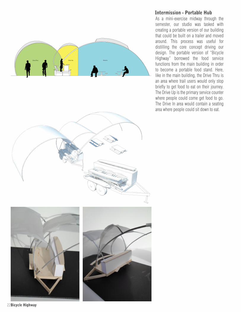
As a mini-exercise midway through the semester, our studio was tasked with creating a portable version of our building that could be built on a trailer and moved around. This process was useful for distilling the core concept driving our design. The portable version of “Bicycle Highway” borrowed the food service functions from the main building in order to become a portable food stand. Here, like in the main building, the Drive Thru is an area where trail users would only stop briefly to get food to eat on their journey. The Drive Up is the primary service counter where people could come get food to go. The Drive In area would contain a seating area where people could sit down to eat.
Intermission - Portable Hub

23
Cox Street
Reed
y Ri
ver
Aca
dem
y St
reet
Brid
ge
Floor Plan
North Elevation
Building Section
Site Plan
24Bicycle Highway
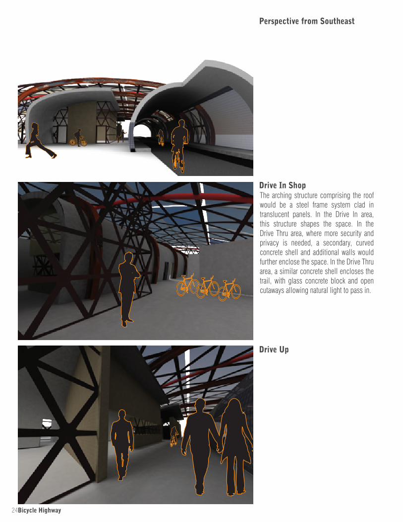
Drive In ShopThe arching structure comprising the roof would be a steel frame system clad in translucent panels. In the Drive In area, this structure shapes the space. In the Drive Thru area, where more security and privacy is needed, a secondary, curved concrete shell and additional walls would further enclose the space. In the Drive Thru area, a similar concrete shell encloses the trail, with glass concrete block and open cutaways allowing natural light to pass in.
Perspective from Southeast
Drive Up
25
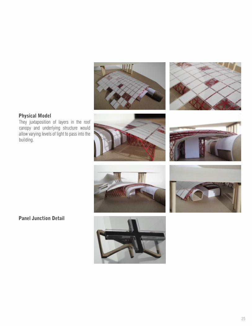
Physical ModelThey juxtaposition of layers in the roof canopy and underlying structure would allow varying levels of light to pass into the building.
Panel Junction Detail
26Essay - Grad Statement
I realized that there is a large gap in my portfolio for the three years that I worked at Jacobs Engineering following my graduation from Clemson and prior to enrolling at UNC Charlotte for graduate school. This is due to most of the work I did at Jacobs being done on confidential projects. It was also rather dull to look at, anyway. Yet, I felt that period of time was an important stage in my development, so I felt compelled to acknowledge it somehow. So, in the interests of not boring anyone by putting a bunch of confidential construction drawings in my portfolio, instead, I’ve opted to include this essay I wrote when applying to graduate school which explains my thoughts as I was preparing to leave Jacobs and how that time and experience influenced my understanding of architecture.
Introduction
Jan 2015Graduate Statement
27
I graduated from Clemson University three years ago with a pre-professional degree in Architecture. I was hired by Jacobs Engineering in Greenville, SC, where I have now worked for the past three years. At the time of my graduation I felt that the best decision for me was to take some time off from school and re-focus myself and think about the things I wanted to accomplish – not only eventually returning to school and completing the track to licensure, but developing my skills and craft as a competent architect regardless of my formal qualifications. I’ve spent the last few years at Jacobs drafting and designing industrial buildings - not nearly as glamorous as what students are prepared for in architecture school - however, I think the experiences that I have gained through my work at Jacobs have been valuable in shaping my views on architecture.
The buildings I design at Jacobs are typically lacking from an aesthetic standpoint – the primary focus is on the bare bones of what makes the building functional and most economical. Having, through my undergraduate studies, experienced architecture primarily as a visual and spatial medium, I wondered, did these buildings really ‘count’ as architecture? Eventually I came to understand that the fundamentals of architecture were still there – programming, planning, material choice, etc. – but they were present without a focus on how the building looks and feels.
My primary reason for returning to finish a professional degree is to fulfill the requirements for licensure. But, despite its being necessary I think there is also an opportunity for me to grow in my understanding of architecture because I will be returning to the academic side of the profession having now both experienced a taste of it architectural practice and having had a prior academic experience through my previous undergraduate program. For me, architecture is finding a creative and efficient way to create a building that meets the client’s needs using all the tools an architect has at his disposal, those tools including: his knowledge of materials/construction products, his understanding of program and spatial arrangements, his understanding of structural systems, and his knowledge of the construction process. This definition helped me reconcile working on nondescript industrial buildings and understanding that they could be just as successful, architecturally, as a high profile civic building or skyscraper.
What I want to get out of school this time around is a more thorough knowledge and understanding of these things from a perspective that I would not get in a professional setting.
I am very much interested in gaining a more in-depth understanding of materials, structural systems, etc… because I think that understanding those elements of architecture is key to putting together a cohesive building. I am interested in any design-build opportunities there might be and opportunities to engage with practicing architects and the real world practice of architecture.
I am looking for opportunities to develop my skills in both an academic and professional setting. This is an opportunity to take what I’ve learned after working in the industry for several years and apply it to projects where there is less pressure from clients, budgets, managers, etc. Very rarely will I have the opportunity to make as many decisions on a real project as I can on one in school – so for me, being able to return to that setting with a fresh perspective is valuable.
While I do not necessarily intend to return to industrial architecture in the future, I think it has been a valuable experience for me. My time spent over the past few years working on simple structures has been time well spent. I hope that I can look back on my next few years of study and also see a valuable experience that has helped shape me as an architect.
“
”

28Parametric Pavilion
About the PrecedentThe pavilion and accompanying landscaping plan were the winning entry in a competition held by the city of Zug to design a public park that would connect two parts of the local library. The library had recently expanded to a neighboring building, which now needed to be connected with the original library building. In between the two library locations existed a partially buried parking garage, which provided a challenging site condition. The design team’s solution was not to hide the parking structure with their scheme for the park, but to further expose it and dress the edge of the structure with vertical wooden
This digital model was generated using a Grasshopper script and Rhino as part of a class focused on parametric design. The script process recreates a precedent project - a pavilion located in a city garden in Zug, Switzerland designed by Ramser-Schmid Architects in collaboration with Planetage Landscape Architects.
Project Background
Fall 20141st Yr Graduate
Nick SenskeUNC Charlotte
----
Parametric PavilionSemesterClass YearProfessorSchool

29
slats. As part of their modifications to the parking structure, the architects designed a pavilion to sit on top of it that would provide a source of shelter for the park’s users. The pavilion sits on top of the garage’s lift and ventilation shaft. It is comprised mainly of laminated brick-like wooden slats which match the wooden slats protruding from the adjacent landscaping.
Source for photos and section:http://www.archdaily.com/531618/city-garden-zug-planetage-landscape-ramser-schmid/
30Parametric Pavilion
SECTION VIEW
SECTION VIEW
original vertices
extr
ude
scal
e
SECTION VIEW
SECTION VIEW
original vertices
extr
ude
scal
e
SECTION VIEW
SECTION VIEW
original vertices
extr
ude
scal
e
SECTION VIEW
SECTION VIEW
original vertices
extr
ude
scal
e
SECTION VIEW
SECTION VIEW
original vertices
extr
ude
scal
e
SECTION VIEW
SECTION VIEW
original vertices
extr
ude
scal
e
SECTION VIEW
SECTION VIEW
original vertices
extr
ude
scal
e
SECTION VIEW
SECTION VIEW
original vertices
extr
ude
scal
e
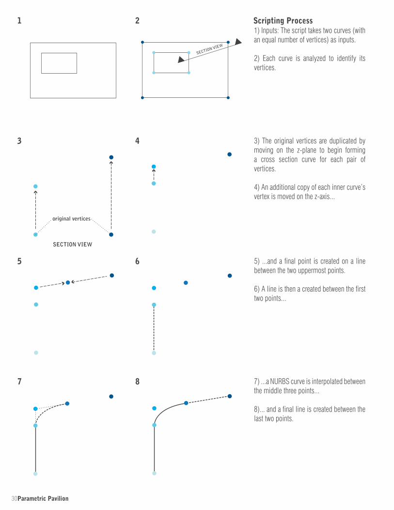
5) ...and a final point is created on a line between the two uppermost points.
6) A line is then a created between the first two points...
3) The original vertices are duplicated by moving on the z-plane to begin forming a cross section curve for each pair of vertices.
4) An additional copy of each inner curve’s vertex is moved on the z-axis...
1) Inputs: The script takes two curves (with an equal number of vertices) as inputs.
2) Each curve is analyzed to identify its vertices.
Scripting Process1 2
3 4
5 6
7 8 7) ...a NURBS curve is interpolated between the middle three points...
8)... and a final line is created between the last two points.
31
SECTION VIEW
SECTION VIEW
original vertices
extr
ude
scal
e
SECTION VIEW
SECTION VIEW
original vertices
extr
ude
scal
e
SECTION VIEW
SECTION VIEW
original vertices
extr
ude
scal
e
9
10
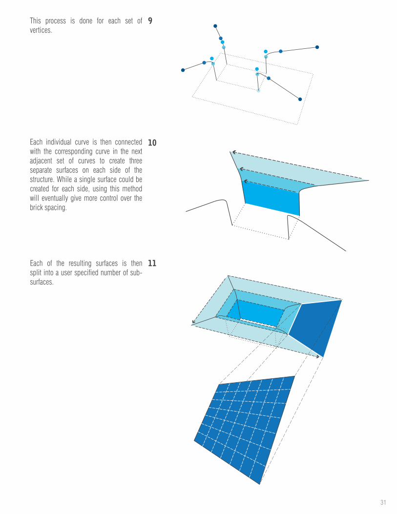
11Each of the resulting surfaces is then split into a user specified number of sub-surfaces.
Each individual curve is then connected with the corresponding curve in the next adjacent set of curves to create three separate surfaces on each side of the structure. While a single surface could be created for each side, using this method will eventually give more control over the brick spacing.
This process is done for each set of vertices.

32Parametric Pavilion
SECTION VIEW
SECTION VIEW
original vertices
extr
ude
scal
e
SECTION VIEW
SECTION VIEW
original vertices
extr
ude
scal
e
SECTION VIEW
SECTION VIEW
original vertices
extr
ude
scal
e
Using various input values, the user can recreate the Zug Pavilion almost exactly.
The script is actually very flexible, and can be used to create many different forms, including the ones on the next page.
Resulting Form
Each brick is then extruded to give depth and scaled in the horizontal direction to make the bricks overlap.
12) Since some of the resulting surfaces may be curved, each individual sub-surface is broken down to its component geometry and recreated using its vertices so that all resulting geometry is planar.
13) Every other surface is eliminated to leave only the desired brick pattern.
12 13
14

33
rotate
rotate
offset
rotateoffset
offset
coplanar
coplanar
coplanar
rotate
rotate
offset
rotateoffset
offset
coplanar
coplanar
coplanar
rotate
rotate
offset
rotateoffset
offset
coplanar
coplanar
coplanar
rotate
rotate
offset
rotateoffset
offset
coplanar
coplanar
coplanar
The input curves need not be coplanar. The following geometry was created by rotating each curve and offsetting the top curve vertically.
The input curves do not need to be rectangular. The following form can be created with two triangles as inputs. Less regular geometries can be used as well. The script requires only that the two polygons have the same number of vertices.
Each of the following variations is made with the same two base curves, but different parameters for height, brick density, and brick depth.
Variations
By using some of the intermediate geometry produced by the script for reference and using the script several times, multiple iterations of the process can be combined and stacked.
34Old Concord Culture Hub
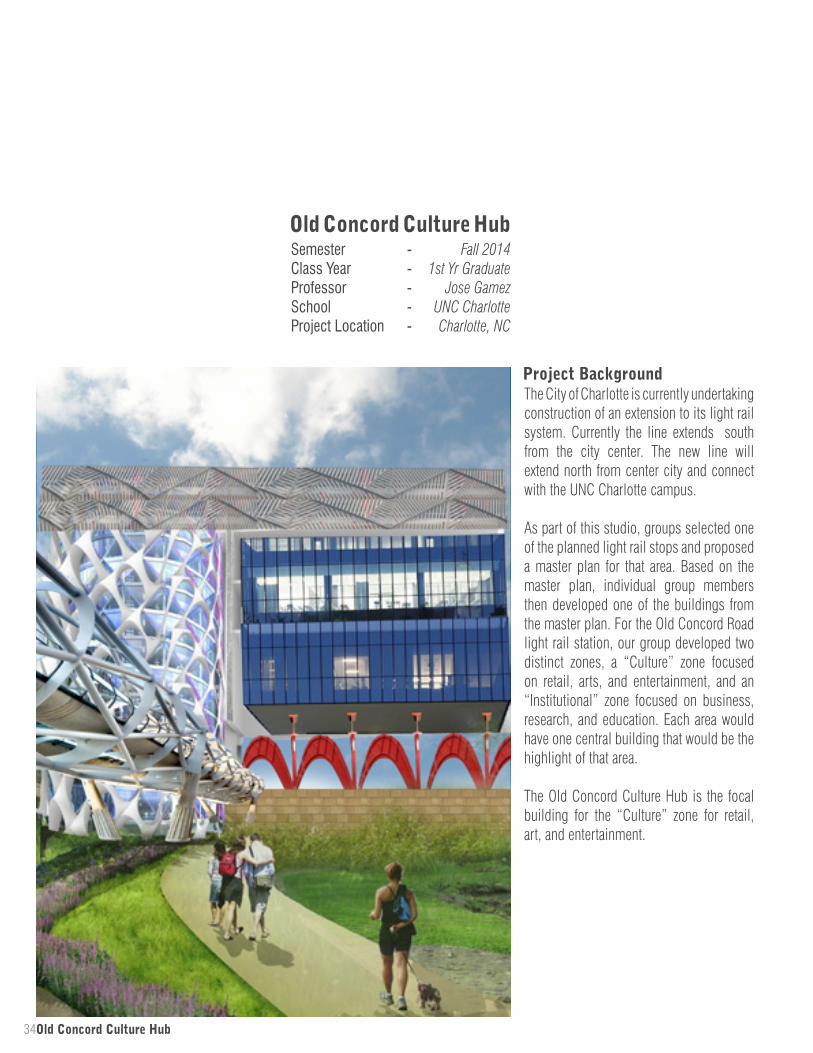
The City of Charlotte is currently undertaking construction of an extension to its light rail system. Currently the line extends south from the city center. The new line will extend north from center city and connect with the UNC Charlotte campus.
As part of this studio, groups selected one of the planned light rail stops and proposed a master plan for that area. Based on the master plan, individual group members then developed one of the buildings from the master plan. For the Old Concord Road light rail station, our group developed two distinct zones, a “Culture” zone focused on retail, arts, and entertainment, and an “Institutional” zone focused on business, research, and education. Each area would have one central building that would be the highlight of that area.
The Old Concord Culture Hub is the focal building for the “Culture” zone for retail, art, and entertainment.
Project Background
Fall 20141st Yr Graduate
Jose GamezUNC CharlotteCharlotte, NC
-----
Old Concord Culture HubSemesterClass YearProfessorSchoolProject Location
35
CLASSROOMS 3500 sf
ADMIN
1500 sf
STORAGE
SHOPSHOP
GALLERY
AUDITORIUM/AMPHITHEATER
SMALLEXHIBITION
LARGEEXHIBITION
ROOFPLAZA
CAFE ANDTERRACE
REHEARSAL/ACTIVITY
1500 sf
1000 sf
1000 sf
4000 sf
700 seats
1200 sf
REHEARSAL/ACTIVITY
1200 sf
3800 sf
8500 sf
3600 sf
CLASSROOMS 3500 sf
ADMIN
1500 sf
STORAGE
SHOPSHOP
GALLERY
AUDITORIUM/AMPHITHEATER
SMALLEXHIBITION
LARGEEXHIBITION
ROOFPLAZA
CAFE ANDTERRACE
REHEARSAL/ACTIVITY
1500 sf
1000 sf
1000 sf
4000 sf
700 seats
1200 sf
REHEARSAL/ACTIVITY
1200 sf
3800 sf
8500 sf
3600 sf
CLASSROOMS 3500 sf
ADMIN
1500 sf
STORAGE
SHOPSHOP
GALLERY
AUDITORIUM/AMPHITHEATER
SMALLEXHIBITION
LARGEEXHIBITION
ROOFPLAZA
CAFE ANDTERRACE
REHEARSAL/ACTIVITY
1500 sf
1000 sf
1000 sf
4000 sf
700 seats
1200 sf
REHEARSAL/ACTIVITY
1200 sf
3800 sf
8500 sf
3600 sf
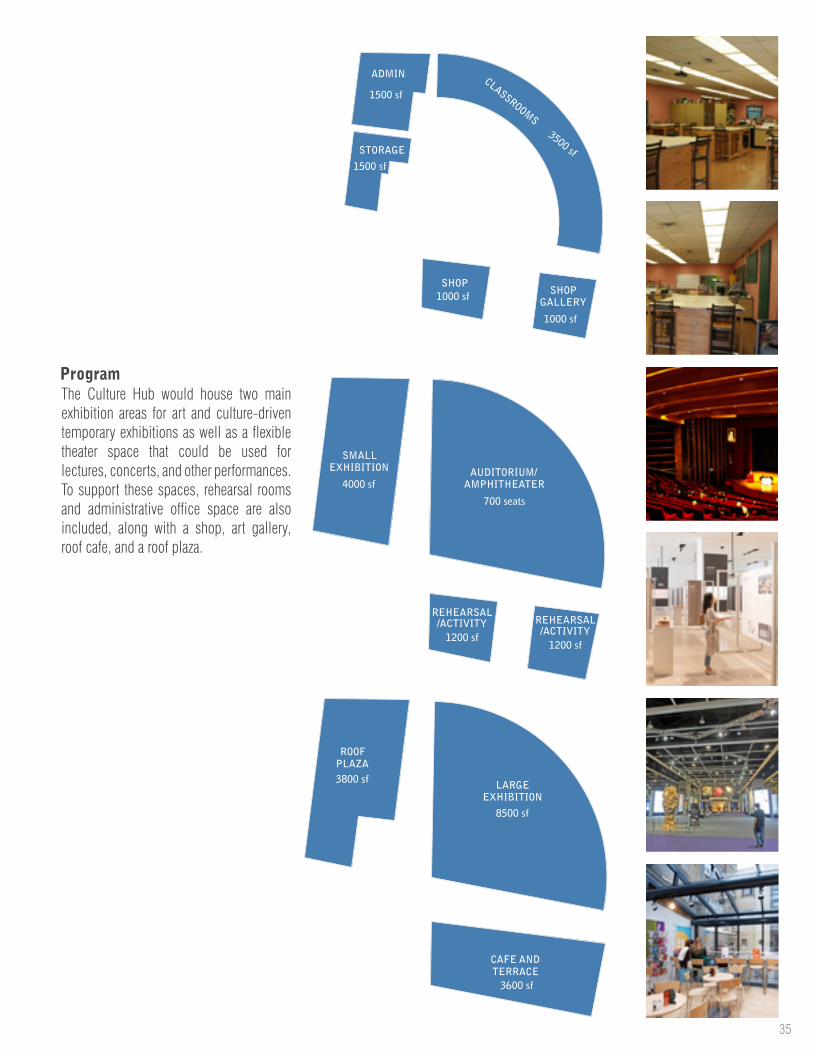
ProgramThe Culture Hub would house two main exhibition areas for art and culture-driven temporary exhibitions as well as a flexible theater space that could be used for lectures, concerts, and other performances. To support these spaces, rehearsal rooms and administrative office space are also included, along with a shop, art gallery, roof cafe, and a roof plaza.
36Old Concord Culture Hub
BR
IDG
E A
BOV
E
TRYON ST
OLD CONCORDE RD
GR
EE
NW
AY
INF
ILL
RA
MP
SITE PLAN @ STREET LVLNORTH
(BE
LOW
)
EL
EVA
TE
D T
RA
CK
S
TR
AC
KS
ON
GR
AD
E
SLOPE
SLOPESLOPE
DOW
N
DOW
N
RA
MP
TO
BR
IDG
E
RA
MP
TO
BR
IDG
E
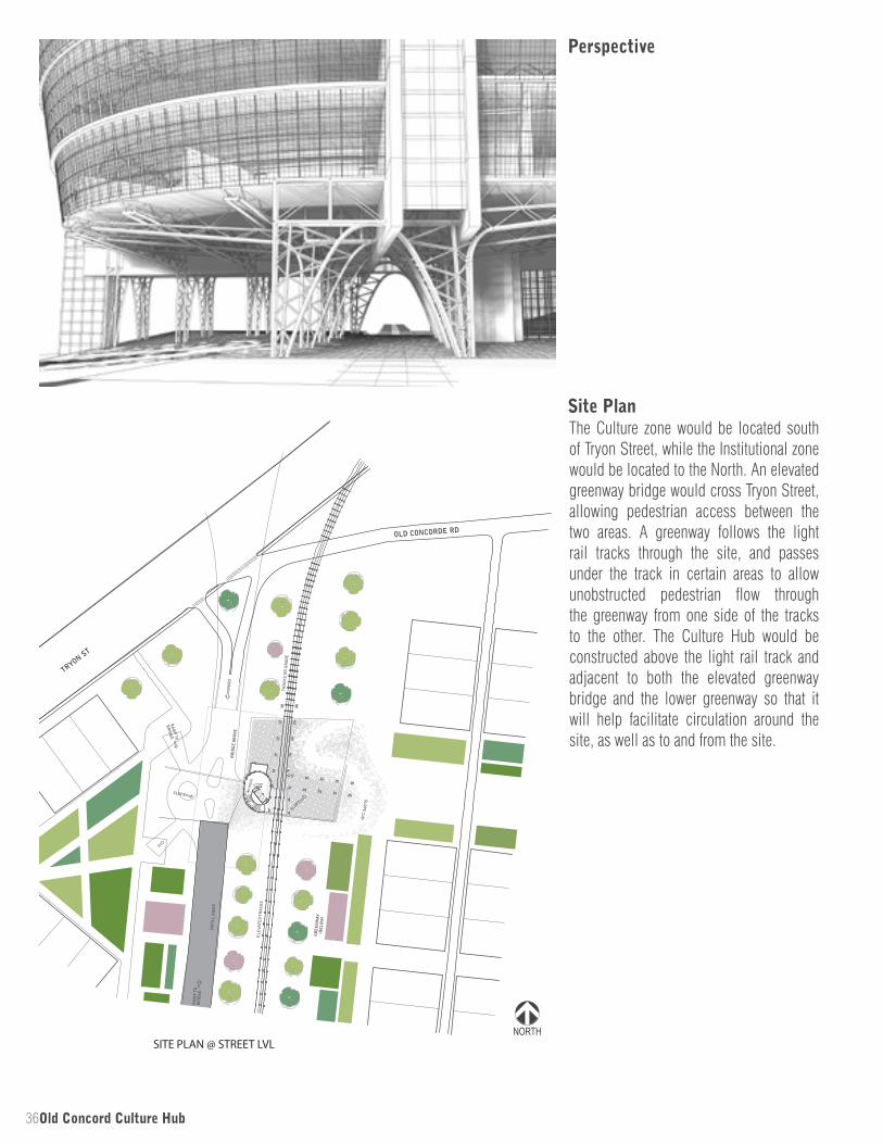
Perspective
Site PlanThe Culture zone would be located south of Tryon Street, while the Institutional zone would be located to the North. An elevated greenway bridge would cross Tryon Street, allowing pedestrian access between the two areas. A greenway follows the light rail tracks through the site, and passes under the track in certain areas to allow unobstructed pedestrian flow through the greenway from one side of the tracks to the other. The Culture Hub would be constructed above the light rail track and adjacent to both the elevated greenway bridge and the lower greenway so that it will help facilitate circulation around the site, as well as to and from the site.
37
Cultural Center
LightRail
LightRail
Hub
Cir
cula
tion
Cultural Center(Cantilever)
LightRail
(Fulcrum)
Hub
Cir
cula
tion
(Dow
nwar
d Fo
rce)
Cultural Center
LightRail
LightRail
Hub
Cir
cula
tion
Cultural Center(Cantilever)
LightRail
(Fulcrum)
Hub
Cir
cula
tion
(Dow
nwar
d Fo
rce)
Cultural Center
LightRail
LightRail
Hub
Cir
cula
tion
Cultural Center(Cantilever)
LightRail
(Fulcrum)
Hub
Cir
cula
tion
(Dow
nwar
d Fo
rce)
Cultural Center
Hub
C
ircu
lati
on
Lig
ht R
ailVertical
HubCirculation
Axis
Horizontal Site Circulation Axis
Site Circulation Axis
Cultural Center
Hub
C
ircu
lati
on
Lig
ht R
ailVertical
HubCirculation
Axis
Horizontal Site Circulation Axis
Site Circulation Axis
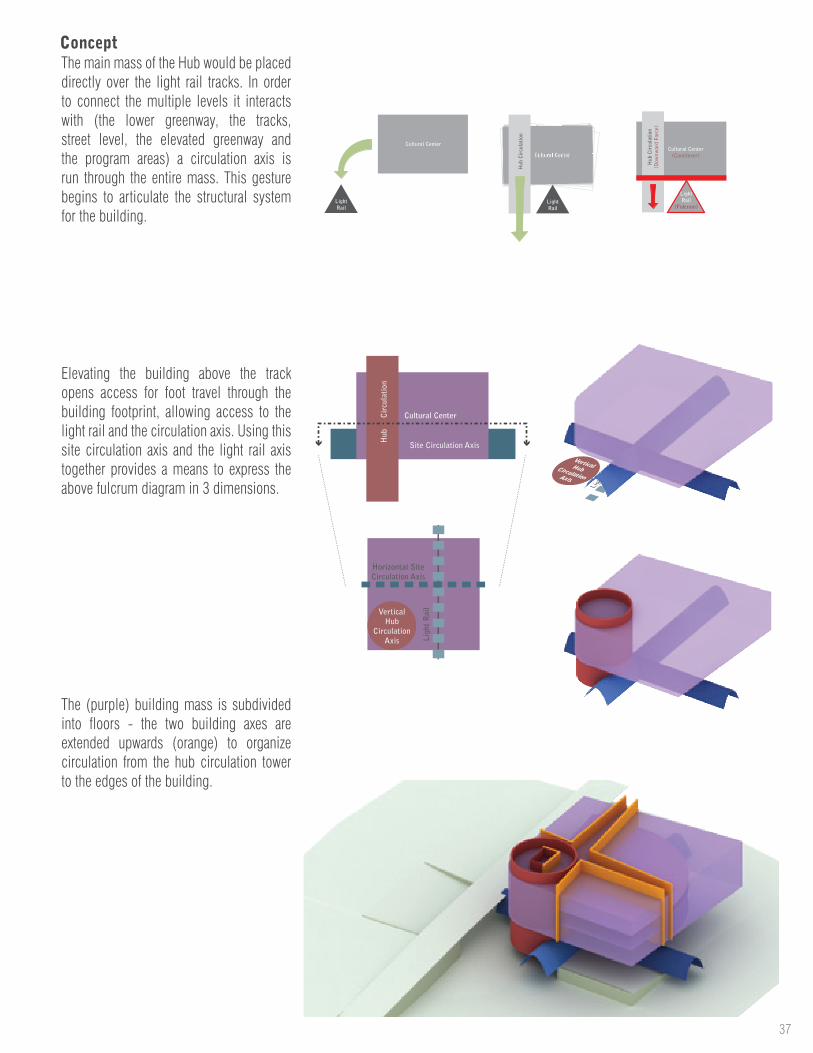
The (purple) building mass is subdivided into floors - the two building axes are extended upwards (orange) to organize circulation from the hub circulation tower to the edges of the building.
Elevating the building above the track opens access for foot travel through the building footprint, allowing access to the light rail and the circulation axis. Using this site circulation axis and the light rail axis together provides a means to express the above fulcrum diagram in 3 dimensions.
The main mass of the Hub would be placed directly over the light rail tracks. In order to connect the multiple levels it interacts with (the lower greenway, the tracks, street level, the elevated greenway and the program areas) a circulation axis is run through the entire mass. This gesture begins to articulate the structural system for the building.
Concept
38Old Concord Culture Hub
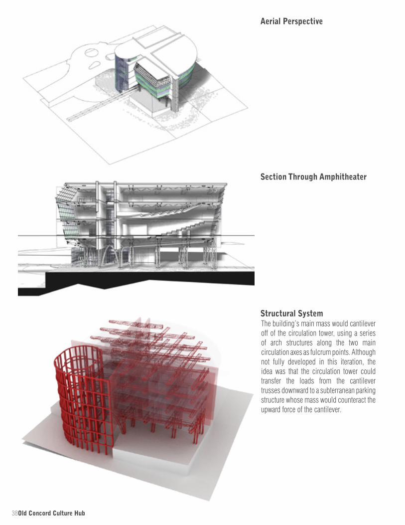
Structural System
Aerial Perspective
Section Through Amphitheater
The building’s main mass would cantilever off of the circulation tower, using a series of arch structures along the two main circulation axes as fulcrum points. Although not fully developed in this iteration, the idea was that the circulation tower could transfer the loads from the cantilever trusses downward to a subterranean parking structure whose mass would counteract the upward force of the cantilever.

39
ROOF PLAZA
CAFE
LARGE EXHIBITIONHALL
CAFE SEATING
BREAKROOM
ADMIN
AMPHITORIUM
CLASSROOMS
LOCALGALLERY
SHOP
ELEVATED GREENWAY
PLAZA
SMALL EXHIBITION
HALL
AMPHITORIUM
REHEARSAL/ ACTIVITY
SPACE REHEARSAL/ ACTIVITY
SPACE
GROUND LEVEL PLAN @ TRYON
STORAGE
FREIGHT
FIRST FLOOR PLAN
SECOND FLOOR PLAN
THIRD FLOOR/ROOF TERRACE
FOYER
ELEV
UP
UP
UP
UP
UP
UP
UP
UP
DN
DN
FOYER
ELEV
FOYER
ELEV
LOBBY
ELEV
PLAZA
PLAZA
ELEV
LIG
HT
RA
ILLI
GH
T R
AIL
AB
OV
E
GREENWAY LEVEL PLAN1201050
2201050
3201050
4201050
5201050
NORTH
First Floor PlanThe primary building mass that contains most of the building’s program starts one level above street level. The elevated greenway bridge has direct access to this level.
This level contains the administration area, hub shop/gallery, and lower level auditorium access.
The ground level provides access to pedestrians from Tryon Street and the retail/entertainment area of the master plan. This level contains a paved plaza situated beneath the building mass. A curved pathway blends the natural landscape of the greenway with the hardscape beneath the building.
Ground Level Plan
Lower Greenway Level PlanThis level provides access to the cultural hub from the lower greenway and access to subterranean parking.
40Old Concord Culture Hub
ROOF PLAZA
CAFE
LARGE EXHIBITIONHALL
CAFE SEATING
BREAKROOM
ADMIN
AMPHITORIUM
CLASSROOMS
LOCALGALLERY
SHOP
ELEVATED GREENWAY
PLAZA
SMALL EXHIBITION
HALL
AMPHITORIUM
REHEARSAL/ ACTIVITY
SPACE REHEARSAL/ ACTIVITY
SPACE
GROUND LEVEL PLAN @ TRYON
STORAGE
FREIGHT
FIRST FLOOR PLAN
SECOND FLOOR PLAN
THIRD FLOOR/ROOF TERRACE
FOYER
ELEV
UP
UP
UP
UP
UP
UP
UP
UP
DN
DN
FOYER
ELEV
FOYER
ELEV
LOBBY
ELEV
PLAZA
PLAZA
ELEV
LIG
HT
RA
ILLI
GH
T R
AIL
AB
OV
E
GREENWAY LEVEL PLAN1201050
2201050
3201050
4201050
5201050
NORTH
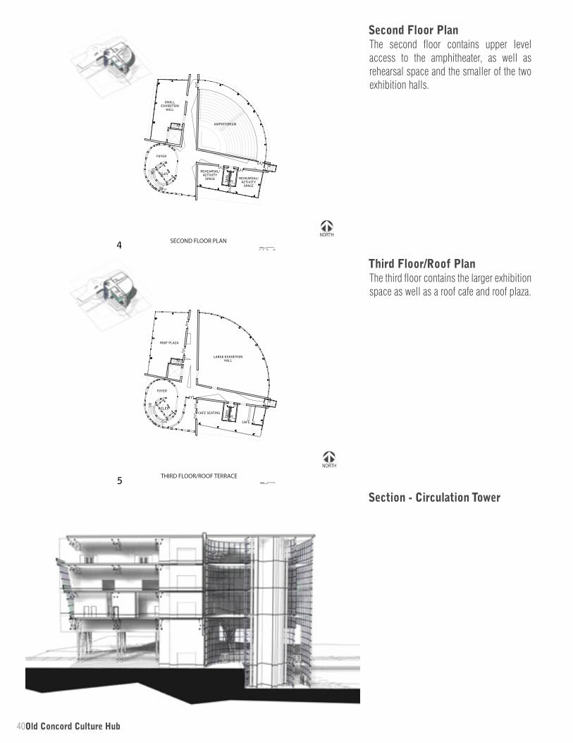
Section - Circulation Tower
Third Floor/Roof PlanThe third floor contains the larger exhibition space as well as a roof cafe and roof plaza.
The second floor contains upper level access to the amphitheater, as well as rehearsal space and the smaller of the two exhibition halls.
Second Floor Plan
41
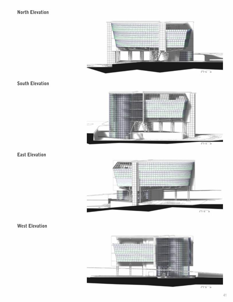
West Elevation
South Elevation
North Elevation
East Elevation