architectural exit device 7000 series exit · pdf fileyale’s 7000 series exit ......
TRANSCRIPT

7000 SERIESARCHITECTURAL EXIT DEVICE
AR
CH
ITE
CT
UR
AL 7000 C
ATA
LOG
E X I T

PEACE OF MIND
YALE® 7000 INTRODUCTION
Yale 7000 Series exit devices deliver an unparalleled combination ofdurability, breadth of line, innovation and aesthetics.
As the most recognized name in the door hardware industry, Yale offersa proven selection of hard-working exit devices. The simple, clean linesof our wide and narrow stile devices are visually appealing and bring agracious totality to the Yale line of locks and hardware.
To meet electronic access control needs, Yale’s 7000 series exit devicescome with a full array of electromechanical options and accessories. The7000 series can be effortlessly integrated into existing security or firealarm systems to ensure every opening is safeguarded.
Today’s architecture stresses the safety and security of a building’scontents, the most important of these being people. Reducing theconsequences of potential risks is the goal of any designer. By mountingpanic and fire exit devices, vandals are deterred, but swift, unobstructedegress is permitted. Yale’s 7000 Series exit devices meet life safety codesand fire safety requirements, allowing for local ordinances to be met andallowing peace of mind for the people inside.
Page 2
Introduction . . . . . . . . . . . .2-3Functions . . . . . . . . . . . . . . .4-57100 Introduction &
Applications . . . . . . . . . . .6-77150(F) SquareBolt® . . . . . . . .87100(F) Rim . . . . . . . . . . . . . .97110(F) SVR . . . . . . . . . . . .107170(F) SVR . . . . . . . . . . . .117120(F) CVR . . . . . . . . . . . .127160(F) CVR . . . . . . . . . . . .137130(F) Mortise . . . . . . . . . .147100 Series Trim . . . . . . .15-177200M Introduction &
Applications . . . . . . . . . . . .187250M(F) SquareBolt . . . . . .197200M(F) Rim . . . . . . . . . . .207210M(F) SVR . . . . . . . . . . .217220M(F) CVR . . . . . . . . . .227200M Series Trim . . . . . . . .237200 Introduction &
Applications . . . . . . . . . . . .247250 SquareBolt . . . . . . . . . .257200 Rim . . . . . . . . . . . . . . .267210 SVR . . . . . . . . . . . . . . .277220 CVR . . . . . . . . . . . . . .287200 Series Trim . . . . . . . . .29Electrified Exit Devices . .30-40Mullions . . . . . . . . . . . . . . . .41Strikes . . . . . . . . . . . . . . . . . .42Options . . . . . . . . . . . . . . . .43Cylinders . . . . . . . . . . . . . . .44Facts and Figures . . . . . . . . .45Sample Specifications . . . . . .46How to Order . . . . . . . . . . .47
CONTENTS
7000 Series Exit Device
7000 SERIES FEATURES
Durability• Steel chassis and heavy-duty
components for superior strength, robustness and lower maintenance
Breadth and Innovation• Full range of mechanical and
electromechanical options for security and life safety applications
• Patented security features including SquareBolt®
latchbolts (Pat. no. 5,605,362) and Free-Wheeling levers(Pat. no. 4,920,773)
Aesthetics• Clean, modern, sleek design• High-quality attractive
architectural finishes deliver consistency and durability
7100(F) SERIES
A conventional exit device forsingle swing doors or pairs ofdoors of metal, wood or compositeconstruction.
7200M(F) SERIES
A narrow appearance exit devicedesigned for wide or flush stiledoors of metal, wood or compositeconstruction.
7200 SERIES
A narrow stile exit devicecompatible with the aesthetics andfunction requirements ofcontemporary doors of aluminumor metal construction.

INTRODUCTION CONT.
Page 37000 Series Exit Device
SQUAREBOLT® EXIT DEVICE
A revolutionary security and safetyexit device from Yale, the SquareBolt’spatented design (Pat. no. 5,605,362)presents an improved physicalbarrier over standard rim latchbolts.
Available in wide stile, narrow stile,and narrow appearance designs, theSquareBolt exit device locks intoplace and stays there. Credit cards,crowbars, door rattling and shakingare resisted, significantly reducingthe threat of unauthorized entry.
ELECTRIFIED EXIT DEVICES
The Yale 7000 Series exit deviceoffers a complete range ofelectrical options:• Latch Pullback• Electric Dogging• Mortise Device Trim Control• Touchbar Monitor or Signaling• Outside Trim Monitor or Signaling• Bolt Position Monitor or Signaling• SecureX® Delayed Egress• Electric Trim Control• Exit AlarmContinuity in appearance, securityand functions with the 7000 Seriesmechanical exit devices is maintained.
7000 Series Electrified Exit Devicesmay be integrated into the securityand alarm monitoring systems ofmost buildings.
HEAVY-DUTY TRIM
• The 620F/650F Series trim provides significant vandal- resistant benefits:- Patented Free-Wheeling levers(not available on mortise trim)- Through-bolting with
threaded studs- Beveled sides for resistance
to attack- Heavy-duty solid forged
escutcheon- Flush cylinder
• Eight lever designs• Particularly recommended for
use with the 7150 SquareBolt®
Exit Device• Retrofits existing Yale installations
FREE-WHEELING LEVER TRIM
All Yale exit device trims (except mortise trim) feature the uniqueFree-Wheeling lever mechanism,similar to our 5400LN cylindricallock. This patented Free-Wheelingtrim (Pat. no. 4,920,773) features aclutch mechanism which allows thelever to float down 60 degrees whenoperated in the locked condition,greatly improving vandal resistance.
PERFORMANCE STANDARDS
UL - cUL Panic Exit Listing: Doorsup to 4'0" x 10'0"* (1.22m x3.05m), single swing or pairs.
UL - cUL Fire Exit Label: Doorsup to 4'0" x 10'0" (1.22m x2.44m), single swing or pairs.*UL does not set heightlimitations on panic devices.
Listing AgencyListing Number
Panic ExitDevics
Fire ExitDevices
UnderwritersLaboratories, Inc.
(FVSR) (GXHX)
California FireMarshal
4140-0257:111
3725-0257:112
New York City MEA: 477-91-E
B.H.M.A.(ANSI A156.3)
Directory of CertifiedExit Devices
B.H.M.A.(ANSI A156.24)
Directory of CertifiedDelayed Egress ExitDevices
WARRANTY
• Mechanical exit devices and heavy-duty trim carry a five-yearlimited warranty.
• Utility-duty trim carries a one-year limited warranty.
• Electrical options and componentscarry a one-year limited warranty.
FINISHES
BHMASymbol
Description
605 Bright Brass, Clear Coated
605e* Bright Brass, PVD
606 Satin Brass, Clear Coated
606e* Satin Brass, PVD
609Satin Brass, Blackened,Satin Relieved, Clear Coated
611 Bright Bronze, Clear Coated
612 Satin Bronze, Clear Coated
613 Satin Bronze, Oxidized and Oil Rubbed
613e* Satin Bronze, Oxidized, PVD
616 Satin Bronze, Blackened,Satin Relieved, Clear Coated
619 Satin Nickel Plated, Clear Coated
625 Bright Chrome Plated
626 Satin Chrome Plated
629 Bright Stainless Steel
630 Satin Stainless Steel
Finishes For Touchbar Scalps Only
WU Unfinished wood veneer
WF Walnut, stained and sealed
SS Stainless Steel
BN* Semi-gloss black fused polymer
*Standard for device accent parts and strikes
END CAP
The 7000 series impact-resistant end cap isdesigned with heavy-dutymaterial with three screwholes in strategic locations to resistabuse and maintain functionality.The ECK7 kit is available for easyretrofit to existing exit devices.
PVD LIFETIME FINISH
Physical Vapor Deposition (PVD) is a technologically advanced finishcoating that provides the ultimatesurface protection againstenvironmental elements and everydaywear and tear. PVD matches clearcoated finishes in appearance, yetsurpasses them in durability. Yalewarrants all its PVD finishes againstcorrosion, tarnish, wear, discoloringand peeling for the lifetime of thepart to which it has been applied.Ask your sales representative forspecific warranty information.
*PVD Lifetime finish

FUNCTIONS
Page 4 7000 Series Exit Device
KNOB OR LEVER TRIMS
SquareBolt®
7150(F)7250M(F)
7250
Rim7100(F)
7200M(F)7200
SurfaceVertical Rod
7110(F)7170(F90)7210M(F)
7210
ConcealedVertical Rod
7120(F)7160(F90)7220M(F)
7220
Mortise7130(F)
TypeANSI
FunctionNo.
Function Description
Inside Outside Inside Outside Inside Outside Inside Outside Inside Outside
Exit Only/Blank Plate
01–
Exit only, no trim.Exit only, blank plate.
Dummy 02Entrance by trim whenactuating bar is lockeddown.
Nightlatch 03
Entrance by trim whenlatchbolt is retracted bykey. Key removable onlywhen locked.
Classroom 08Entrance by knob or lever.Key locks or unlocks knobor lever.
Storeroom 09
Entrance by knob or leveronly when released bykey. Key removable onlywhen locked.
Passage 14
Entrance by trim whenlatchbolt is released byknob or lever. Knob orlever always active, nocylinder.
Note: 09 and Free-Wheeling 02 achieved with a single modification at installation.
DOUBLE CYLINDER EXIT DEVICE LEVER TRIMS
SquareBolt®
7150(F)-2Rim
7100(F)-2Mortise
7130(F)-2Type
ANSI FunctionNo.
Function Description
Inside Outside Inside Outside Inside Outside
Classroom 08Entrance by lever. Key either sidelocks or unlocks lever.
FUNCTIONS
Page 57000 Series Exit Device
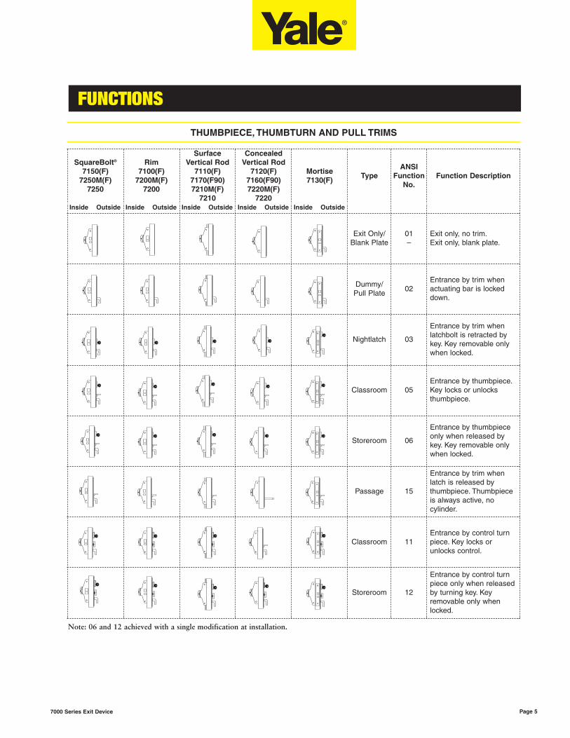
THUMBPIECE, THUMBTURN AND PULL TRIMS
SquareBolt®
7150(F)7250M(F)
7250
Rim7100(F)
7200M(F)7200
SurfaceVertical Rod
7110(F)7170(F90)7210M(F)
7210
ConcealedVertical Rod
7120(F)7160(F90)7220M(F)
7220
Mortise7130(F)
TypeANSI
FunctionNo.
Function Description
Inside Outside Inside Outside Inside Outside Inside Outside Inside Outside
Exit Only/Blank Plate
01–
Exit only, no trim.Exit only, blank plate.
Dummy/Pull Plate
02Entrance by trim whenactuating bar is lockeddown.
Nightlatch 03
Entrance by trim whenlatchbolt is retracted bykey. Key removable onlywhen locked.
Classroom 05Entrance by thumbpiece.Key locks or unlocksthumbpiece.
Storeroom 06
Entrance by thumbpieceonly when released bykey. Key removable onlywhen locked.
Passage 15
Entrance by trim whenlatch is released bythumbpiece. Thumbpieceis always active, nocylinder.
Classroom 11Entrance by control turnpiece. Key locks orunlocks control.
Storeroom 12
Entrance by control turnpiece only when releasedby turning key. Keyremovable only whenlocked.
Note: 06 and 12 achieved with a single modification at installation.

7100 SERIES APPLICATIONS
Page 6 7000 Series Exit Device
INTRODUCTION
The 7100 is the perfect choice for wide stile panic and fire-rated applications. The smooth architectural linesprovide pleasing aesthetics to accent a building’s appearance, and looks aren't always deceiving. Beneath thestrong exterior lie the components to meet the demanding security and access control needs of today. TheSecureX® delayed egress option is just one of the many electromechanical options offered to enhance security.Complementing the 7100 Series with the 600F Series heavy-duty trim completes the package for a heavy-duty,security hardware package.
APPLICATIONS
Single Door UL Listing Maximum Opening Application
SquareBolt®
7150/7150-2 Panic 4' x *Surface applied; single-point latching.
7150F/7150F-2 3 Hr. 4' x 8'
Rim
7100/7100-2 Panic 4' x *Surface applied; single-point latching.
7100F/7100F-2 3 Hr. 4' x 8'
Mortise
7130/7130-2 Panic 4' x *
Mortised in door; single-point latching.7130F/7130F-2 1-1/2 Hr. 4' x 9'
7130F/7130F-2 3 Hr. 4' x 8'
Surface Vertical Rod
7110 Panic 4' x 8'Surface applied; one- or two-point latching.
7170 Panic 4' x *
Concealed Vertical Rod
7120 Panic 4' x 8'Rods concealed in door; one- or two-point latching.
7160 Panic 4' x *
Pair of Doors with Removable
MullionUL Listing Maximum Opening Application
SquareBolt® x SquareBolt®
7150 x 7150 x M100 Series Panic 8' x 10'Two independent active doors with removable mullion.
7150F x 7150F x M100F Series 3 Hr. 8' x 8'
Rim x Rim
7100 x 7100 x M100 Series Panic 8' x 10'Two independent active doors with removable mullion.
7100F x 7100F x M100F Series 3 Hr. 8' x 8'
*UL does not set a door height limitation on panic applications.

7100 SERIES APPLICATIONS
Page 7
APPLICATIONS
7000 Series Exit Device
Pair of Doors UL Listing Maximum Opening Application
Surface Vertical Rod
7110 x 7110 Panic 8' x 8' Two independent doors with two-point latching, swinging in thesame direction.7110F x 7110F 3 Hr. 8' x 8'
7170 x 7170 Panic 8' x * Two independent doors with one- or two-point latching,swinging in the same direction.7170F90 x 7170F90 1-1/2 Hr. 8' x 10
Surface Vertical Rod (Double Egress)
7110 x 7110 Panic 8' x 8' Two independent doors with two-point latching, swinging inopposite directions.7110F x 7110F 3 Hr. 8' x 8'
7170 x 7170 Panic 8' x * Two independent doors with one- or two-point latching,swinging in opposite directions.7170F90 x 7170F90 1-1/2 Hr. 8' x 10'
Surface Vertical Rod x Mortise
7110 x 7130 Panic 8' x 8'Overlapping astragal required for 3-hour openings. Coordinator required with standard ANSI strike.
7110F x 7130F 3 Hr. 8' x 8'
7110F x 7130F 1-1/2 Hr. 8' x 9'
7170 x 7130 Panic 8' x * Overlapping astragal required for fire-rated openings.Coordinator required with standard ANSI strike.7170F90 x 7130F 1-1/2 Hr. 8' x 9'
Concealed Vertical Rod
7120 x 7120 Panic 8' x 8' Two independent metal doors with two-point latching, swingingin the same direction.7120F x 7120F 3 Hr. 8' x 8'
7160 x 7160 Panic 8' x * Two independent metal or wood doors with one- or two-pointlatching, swinging in the same direction.7160F90 x 7160F90 1-1/2 Hr. 8' x 10'
Concealed Vertical Rod (Double Egress)
7120 x 7120 Panic 8' x 8' Two independent metal doors with two-point latching, swingingin opposite directions.7120F x 7120F 3 Hr. 8' x 8'
7160 x 7160 Panic 8' x * Two independent metal or wood doors with one- or two-pointlatching, swinging in opposite directions.7160F90 x 7160F90 1-1/2 Hr 8' x 10'
*UL does not set a door height limitation on panic applications.
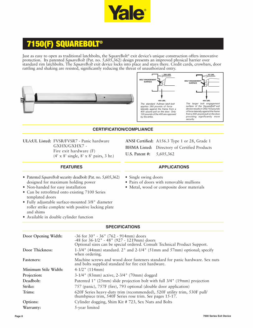
7150(F) SQUAREBOLT®
Page 8 7000 Series Exit Device
Just as easy to open as traditional latchbolts, the SquareBolt® exit device’s unique construction offers innovativeprotection. Its patented SquareBolt (Pat. no. 5,605,362) design presents an improved physical barrier overstandard rim latchbolts. The SquareBolt exit device locks into place and stays there. Credit cards, crowbars, doorrattling and shaking are resisted, significantly reducing the threat of unauthorized entry.
CERTIFICATION/COMPLIANCE
P
FEATURES
• Patented SquareBolt security deadbolt (Pat. no. 5,605,362)designed for maximum holding power
• Non-handed for easy installation• Can be retrofitted onto existing 7100 Series
templated doors• Fully adjustable surface-mounted 3/8" diameter
roller strike complete with positive locking plate and shims
• Available in double cylinder function
APPLICATIONS
• Single swing doors• Pairs of doors with removable mullions• Metal, wood or composite door materials
Door Opening Width: -36 for 30" - 36" (762 - 914mm) doors-48 for 36-1/2" - 48" (927 - 1219mm) doorsOptional sizes can be special ordered. Consult Technical Product Support.
Door Thickness: 1-3/4" (44mm) standard. 2" and 2-1/4" (51mm and 57mm) optional; specify when ordering.
Fasteners: Machine screws and wood door fasteners standard for panic hardware. Sex nuts and bolts supplied standard for fire exit hardware.
Minimum Stile Width: 4-1/2" (114mm)Projection: 3-1/4" (83mm) active, 2-3/4" (70mm) doggedDeadbolt: Patented 1" (25mm) slide projection bolt with full 3/4" (19mm) projectionStrike: 757 (panic), 757F (fire), 793 optional (double door application)Trims: 620F Series heavy-duty trim (recommended), 520F utility trim, 530F pull/
thumbpiece trim, 540F Series rose trim. See pages 15-17.Options: Cylinder dogging, Shim Kit # 723, Sex Nuts and BoltsWarranty: 5-year limited
SPECIFICATIONS
UL/cUL Listed: FVSR/FVSR7 - Panic hardwareGXHX/GXHX7 -Fire exit hardware (F)(4' x 8' single, 8' x 8' pairs, 3 hr.)
ANSI Certified: A156.3 Type 1 or 28, Grade 1
BHMA Listed: Directory of Certified Products
U.S. Patent #: 5,605,362
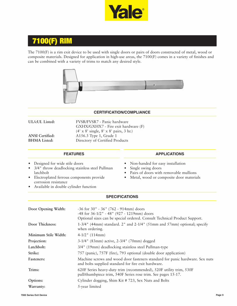
51 & 51BF STANDARD INSTALLATIONS7100(F) RIM
Page 97000 Series Exit Device
The 7100(F) is a rim exit device to be used with single doors or pairs of doors constructed of metal, wood orcomposite materials. Designed for application in high-use areas, the 7100(F) comes in a variety of finishes andcan be combined with a variety of trims to match any desired style.
CERTIFICATION/COMPLIANCE
UL/cUL Listed: FVSR/FVSR7 - Panic hardware GXHX/GXHX7 - Fire exit hardware (F)(4' x 8' single, 8' x 8' pairs, 3 hr.)
ANSI Certified: A156.3 Type 1, Grade 1BHMA Listed: Directory of Certified Products
FEATURES
• Designed for wide stile doors• 3/4" throw deadlocking stainless steel Pullman
latchbolt• Electroplated ferrous components provide
corrosion resistance• Available in double cylinder function
APPLICATIONS
• Non-handed for easy installation• Single swing doors• Pairs of doors with removable mullions• Metal, wood or composite door materials
Door Opening Width: -36 for 30" - 36" (762 - 914mm) doors-48 for 36-1/2" - 48" (927 - 1219mm) doorsOptional sizes can be special ordered. Consult Technical Product Support.
Door Thickness: 1-3/4" (44mm) standard. 2" and 2-1/4" (51mm and 57mm) optional; specify when ordering.
Minimum Stile Width: 4-1/2" (114mm)
Projection: 3-1/4" (83mm) active, 2-3/4" (70mm) dogged
Latchbolt: 3/4" (19mm) deadlocking stainless steel Pullman-type
Strike: 757 (panic), 757F (fire), 793 optional (double door application)
Fasteners: Machine screws and wood door fasteners standard for panic hardware. Sex nuts and bolts supplied standard for fire exit hardware.
Trims: 620F Series heavy-duty trim (recommended), 520F utility trim, 530F pull/thumbpiece trim, 540F Series rose trim. See pages 15-17.
Options: Cylinder dogging, Shim Kit # 723, Sex Nuts and Bolts
Warranty: 5-year limited
SPECIFICATIONS

7110(F) SURFACE VERTICAL ROD
Page 10 7000 Series Exit Device
The 7110(F) is a surface vertical rod exit device to be used on wide stile or flush doors up to 8' where two-point latching is desired.
FEATURES
• Designed for wide stile and flush doors• Handed. Specify hand (field reversible)• Bottom deadbolt for secure latching• Fully adjustable roller strike
APPLICATIONS
• Pairs of doors• Double egress• Metal, wood or composite door materials
Door Opening Width: -36 for 30" - 36" (762 - 914mm) doors-48 for 36-1/2" - 48" (927 - 1219mm) doorsOptional sizes can be special ordered. Consult Technical Product Support.
Door Opening Height: Standard door height 7'. Optional 8' available. For doors over 8', see the 7170(F) SVR.
Door Thickness: 1-3/4" (44mm) standard. 2" and 2-1/4" (51mm and 57mm) optional; specify when ordering.
Minimum Stile Width: 4-1/2" (114mm)
Projection: 3-1/4" (83mm) active, 2-3/4" (70mm) dogged
Latchbolt: Top: 3/4" (19mm) throw, Pullman-type with automatic deadlatchingBottom: 5/8" (16mm) throw deadbolt, held retracted during door swing
Vertical Rods: 1/2" O.D. tubular brass, bronze or stainless steel with rod guides
Strike: Top: Roller type 791 (panic and fire). Bottom: Flush mounted 790 (panic and fire). 794 floor strike optional (threshold openings).
Fasteners: Machine screws and wood door fasteners standard for panic hardware. Sex nuts and bolts supplied standard for fire exit hardware.
Trims: 620F Series heavy-duty trim (recommended), 520F utility trim, 530F pull/thumbpiecetrim, 540F Series rose trim. See pages 15-17.
Options: Cylinder dogging, Shim Kit # 724, Sex Nuts and Bolts, 7010-2, 7010-6, 7010-12 rodextensions, bottom Pullman latch (panic only)
Warranty: 5-year limited
SPECIFICATIONS
CERTIFICATION/COMPLIANCE
UL/cUL Listed: FVSR/FVSR7 - Panic hardwareGXHX/GXHX7 - Fire exit hardware (F) (8' x 8' pairs, 3 hr.)
ANSI Certified: A156.3 Type 2, Grade 1
BHMA Listed: Directory of Certified Products

7170(F90) SURFACE VERTICAL ROD
Page 117000 Series Exit Device
The 7170(F) is a surface vertical rod exit device to be used on wide stile and flush doors up to 10' where two-pointlatching is desired. A Less Bottom Rod (LBR) option is available.
CERTIFICATION/COMPLIANCE
UL/cUL Listed: FVSR/FVSR7 - Panic hardwareGXHX/GXHX7 - Fire exit hardware (F)(8' x 10' pairs, 1-1/2 hr.)
ANSI Certified: A156.3 Type 2, Grade 1
BHMA Listed: Directory of Certified Products
FEATURES
• Designed for wide stile and flush doors• Handed. Specify hand (field reversible)• Interlocking top strike and latch mounting plate• Available less bottom rod (LBR option)
APPLICATIONS
• Pairs of doors• Double egress• Metal or wood doors
Door Opening Width: -36 for 30" - 36" (762 - 914mm) doors-48 for 36-1/2" - 48" (927 - 1219mm) doorsOptional sizes can be special ordered. Consult Technical Product Support.
Door Opening Height: Standard door height 7'. Optional heights specify suffix -8, -9, -10.
Door Thickness: 1-3/4" (44mm) standard. 2" and 2-1/4" (51mm and 57mm) optional; specify when ordering.
Minimum Stile Width: 4-1/2" (114mm)
Projection: 3-1/4" (83mm) active, 2-3/4" (70mm) dogged
Latchbolt: Top: 3/4" (19mm) throw, Pullman-type with automatic deadlatchingBottom: 5/8" (16mm) throw deadbolt, held retracted during door swing
Vertical Rods: 1/2" (13mm) O.D. tubular brass, bronze or stainless steel with rod guides
Strike: Top: 726 (panic and fire). Bottom: Flush-mounted 790 (panic and fire). 794 floor strike optional (threshold openings).
Fasteners: Machine screws and wood door fasteners standard for panic hardware. Sex nuts and bolts supplied standard for fire exit hardware.
Trims: 620F Series heavy-duty trim (recommended), 520F utility trim, 530F pull/thumbpiecetrim, 540F Series rose trim. See pages 15-17.
Electric Strikes: LBR panic-only devices compatible with Folger Adam® 310-4 Series Strikes. SuffixES when ordering.
Options: Cylinder dogging, Shim Kit # 724, Sex Nuts and Bolts, bottom Pullman latch (panic only), Less Bottom Rod (LBR), -8, -9, -10 opening height, 7010-2, 7010-6, 7010-12 rod extensions.
Warranty: 5-year limited
SPECIFICATIONS
Heat-activated door bolt (Popper) -Used when bottom rod is omittedfrom fire exit devices (LBR).
7170(F90) LBR(Less Bottom Rod)

7120(F) CONCEALED VERTICAL ROD
Page 12 7000 Series Exit Device
The 7120(F) is a concealed vertical rod exit device to be used on metal doors only up to 8' in height wheretwo-point latching is desired.
CERTIFICATION/COMPLIANCE
UL/cUL Listed: FVSR/FVSR7 - Panic hardwareGXHX/GXHX7 - Fire exit hardware (F)(8' x 8' pairs, 3 hr.)
ANSI Certified: A156.3 Type 8, Grade 1
BHMA Listed: Directory of Certified Products
FEATURES
• Designed for wide stile and flush doors• Handed. Specify hand (field reversible)• Bottom deadbolt for secure latching• Fully adjustable roller strike
APPLICATIONS
• Pairs of doors• Double egress• Metal doors only
Door Opening Width: -36 for 30" - 36" (762 - 914mm) doors-48 for 36-1/2" - 48" (927 - 1219mm) doorsOptional sizes can be special ordered. Consult Technical Product Support.
Door Opening Height: Standard door height adjustable to 8'. For doors over 8', see the 7160(F) CVR.
Door Thickness: 1-3/4" (44mm) standard. 2" and 2-1/4" (51mm and 57mm) optional; specify when ordering.
Minimum Stile Width: 4-1/2" (114mm)
Projection: 3-1/4" (83mm) active, 2-3/4" (70mm) dogged
Latchbolt: Top: 3/4" (19mm) throw, Pullman-type with automatic deadlatchingBottom: 5/8" (16mm) throw deadbolt, held retracted during door swing
Vertical Rods: 1/2" (13mm) O.D. telescoping tubular rods
Strike: Top: Roller type 791 (panic and fire). Bottom: Flush mounted 790 (panic and fire). 794 floor strike optional (threshold openings).
Fasteners: Machine screws and wood door fasteners standard for panic hardware. Sex nuts and bolts supplied standard for fire exit hardware.
Trims: 620F Series heavy-duty trim (recommended), 520F utility trim, 530F pull/thumbpiecetrim, 540F Series rose trim. See pages 15-17.
Options: Cylinder dogging, Shim Kit # 723, Sex Nuts and Bolts, 7010-2, 7010-6, 7010-12 rodextensions, bottom Pullman latch (panic only).
Warranty: 5-year limited
SPECIFICATIONS

7160(F90) CONCEALED VERTICAL ROD
Page 137000 Series Exit Device
FEATURES
• Designed for wide stile and flush doors • Handed. Specify hand (field reversible)• Mortised top strike• Available less bottom rod (LBR option)
Door Opening Width: -36 for 30" - 36" (762 - 914mm) doors-48 for 36-1/2" - 48" (927 - 1219mm) doorsOptional sizes can be special ordered. Consult Technical Product Support.
Door Opening Height: Standard door height adjustable to 8'. Optional heights specify suffix -9, -10.
Door Thickness: 1-3/4" (44mm) standard. 2" and 2-1/4" (51mm and 57mm) optional; specify when ordering.
Minimum Stile Width: 4-1/2" (114mm)
Projection: 3-1/4" (83mm) active, 2-3/4" (70mm) dogged
Latchbolt: Top: 3/4" (19mm) throw, Pullman-type with automatic deadlatchingBottom: 5/8" (16mm) throw deadbolt, held retracted during door swing
Vertical Rods: 1/2" (13mm) O.D. telescoping tubular rods
Strike: Top: 761 mortised (panic and fire). Bottom: Flush-mounted 790 (panic and fire). 794 floor strike optional (threshold openings).
Fasteners: Machine screws and wood door fasteners standard for panic hardware. Sex nuts and bolts supplied standard for fire exit hardware.
Trims: 540F Series Rose Trim and 620F Series Heavy-Duty Escutcheon Trim. See pages 15 and 16.
Electric Strikes: LBR panic-only devices compatible with Folger Adam® 310-6 Series strikes. Suffix ES when ordering.
Options: Cylinder dogging, Shim Kit # 723, Sex Nuts and Bolts, Less Bottom Rod (LBR), -9, -10 opening height, 7010-2, 7010-6, 7010-12 rod extensions, bottom Pullman latch (panic only).
Warranty: 5-year limited
SPECIFICATIONS
Heat-activated door bolt (Popper) -Used when bottom rod is omittedfrom fire exit devices (LBR).
7160(F90) LBR(Less Bottom Rod)
APPLICATIONS
• Pairs of doors • Double egress• Metal or wood doors
The 7160(F90) is a concealed vertical rod exit device to be used on wood and metal doors up to 10' wheretwo-point latching is desired. A Less Bottom Rod (LBR) option is available.
CERTIFICATION/COMPLIANCE
UL/cUL Listed: FVSR/FVSR7 - Panic hardwareGXHX/GXHX7 - Fire exit hardware (F90)(8' x 10' pairs, 1-1/2 hr.)
ANSI Certified: A156.3 Type 7 and 8, Grade 1
BHMA Listed: Directory of Certified Products

7130(F) MORTISE
Page 14 7000 Series Exit Device
The 7130(F) is an exit device integrated with the Yale® 8700 Series Mortise Lock for use on single doors oractive leaf of a pair of doors where life safety and extra security are required. The 8700 Series Mortise Lockused is modified for use with the exit device only. The standard 8700 mortise lock cannot be used.
CERTIFICATION/COMPLIANCE
UL/cUL Listed: FVSR/FVSR7 - Panic hardwareGXHX/GXHX7 - Fire exit hardware (F)(4' x 8' single, 8' x 8' pairs, 3 hr.)(4' x 9' single, 8' x 9' pairs, 1-1/2 hr.)
ANSI Certified: A156.3 Type 3, Grade 1
BHMA Listed: Directory of Certified Products
FEATURES
• Designed for wide stile and flush doors • Handed; specify hand• Two-piece mechanical 3/4" throw deadlocking
stainless steel latchbolt• Easily disassembles for maintenance and service• Available in double cylinder function
APPLICATIONS
• Single swing doors• Pairs of doors with vertical rod devices or
automatic flush bolts• Metal, wood or compatible door materials
Door Opening Width: -36 for 30" - 36" (762 - 914mm) doors-48 for 36-1/2" - 48" (927 - 1219mm) doorsOptional sizes can be special ordered. Consult Technical Product Support.
Door Thickness: 1-3/4" (44mm) standard. 2" and 2-1/4" (51mm and 57mm) optional; specify when ordering.
Minimum Stile Width: 4-1/2" (114mm)Projection: 3-1/4" (83mm) active, 2-3/4" (70mm) doggedLatchbolt: Two piece mechanical 3/4" (19mm) deadlocking stainless steel with anti-friction
insert and auxiliary deadlocking latchStrike: Curved lip, non-handed 798. Optional 712 for door pairs with astragals.
Optional 718 open back strike.Fasteners: Machine screws and wood door fasteners standard for panic hardware. Sex nuts and
bolts supplied standard for fire exit hardware.Trims: 650F Series heavy-duty trim (recommended), 550F utility trim, 560F cylinder x
pull/thumbpiece trim. See pages 15-17.Electric Strikes: Compatible with Folger Adam® 300, 500, 600, 700 Series strikes (consult factory for
specific model).Options: Cylinder dogging, Shim Kit # 723, Sex Nuts and Bolts.Warranty: 5-year limited.
SPECIFICATIONS
Order As Follows, According To Function.
7130-K5(F)
(01) Exit only
(02) Entry by pull or rigid knob when dogged.
(03) Key retracts latchbolt
Electrical control for 552F and 652F knob trim,w/wo key override.
7130-L5(F)
(02) Entry by rigid lever when dogged.
(03) Key retracts latchbolt.
Electrical control for 556F and 652F lever trim,w/wo key override.
7130-T5(F)(02) Entry by pull when dogged.(03) Key retracts latchbolt.
7130-K8(F)(08) Entry by knob lock/unlocked by key or knobonly (passage)
7130-L8(F)(08) Entry by lever lock/unlocked by key or leveronly (passage)
7130-L8(F)-2(08) Entry by lever lock/unlocked by key either sideor lever only (passage)
7130-T8(F)(05) Entry by thumbpiece lock/unlocked by key orthumbpiece only (passage)

7100 SERIES EXIT DEVICE TRIM
Page 157000 Series Exit Device
620F/650F SERIES HEAVY-DUTY TRIM
Yale's heavy-duty exit device trim features vandal resistant Free-Wheeling trim to be used for high-frequencyapplications or on doors subject to abuse. Free-Wheeling is not available on mortise trim.• Trim through-bolts to exit device for strength.• Beveled sides improve attack resistance.• Solid forged escutcheon resists vandalism and abuse.• Flush cylinder in 6-pin applications for additional
security.• 1-3/4" (44mm) door standard. For doors through.
2-1/4" (57mm) or shim-mounted devices, specify on order.
• Dimensions: 3' x 10-1/4" x 13/16" (76mm x 260mm x 19mm).
• See page 44 for cylinder options. 1-1/2" mortise cylinder required for mortise trim.
• Available with AR, AU, CR, JN, MO, PB, PN, VI lever designs. See page 17.
• Trim ordering example: AU626F x 626 x RHR.• 5-year limited warranty.
Application CylinderExit Only
Blank PlateNightlatch
DummyTrim
Rigid Lever
Dummy Trim Free-Wheeling
Passage Classroom Storeroom Nightlatch
7100(F)7150(F)7110(F)7120(F)7160(F)7170(F)
Rim 620F 621F** 629F 628F* 628F 626F 626F* 627F
7130(F) Mortise 620F 651F** 658F – 658F 656F – 656F
7100(F)-27150(F)-2
Rim xRim
– – – – – 626F – –
7130(F)Mortise x
Rim– – – – – 656F – –
ANSI – 03 02 02 14 08 09 03
*09 and Free-Wheeling 02 achieved with single trim modification at installation.**Not recommended for use with surface or concealed vertical rod devices.
121 CYLINDER ONLY NIGHTLATCH TRIM
• Application: 7100(F) and 7150(F) exit devices. Not recommended for surface or concealed vertical rod devices.• Must specify rim cylinder when ordering. See page 44 for cylinder options.
Function Description Nightlatch Access by Key
Model No. 121
ANSI 03

7100 SERIES EXIT DEVICE TRIM
Page 16 7000 Series Exit Device
520F/550F WIDE ESCUTCHEON UTILITY TRIM
• Through-bolted: 1-3/4" (44mm) door standard. For doors through 2-1/4" (54mm) or shim-mounted devices, specify on order.
• Dimensions: see page 45.• For cylinder options, see page 44.
• Available with all lever and knob designs except CA. See page 17.
• Ordering example: MO528F x 630 x LHR
• 1-year limited warranty.
Applications CylinderExit Only
Blank PlateNightlatch
DummyRigid Lever
DummyFree-
WheelingPassage
Classroom/Storeroom
NightlatchDummy
Trim RigidKnob
PassageActiveKnob
Classroom/Storeroom
Nightlatch
7100(F)7110(F)7120(F) 7150(F)7170(F)
Rim 520F 521F** 529F 528F** 528F 526F** 527F 525F 524F 522F** 523F
7130(F) Mortise 520F 551F** 558F – 558F 556F† 556F 554F 554F 552F† 552F
ANSI – 03 02 02 14 08/09 03 02 14 08/09 03
540F SERIES ROSE TRIM
• 540F rose trim for stock doors (161 Prep). Type 161 stock door trim, if used with 7100(F), 7150(F), or 7110(F) exit devices.
• Through-bolted. 1-3/4" (44mm) door standard. For doors thru 2-1/4" (57mm) or shim mounted devices, specify on order.
• AU, PB, MO and CA trim designs. See page 17.• Accepts cylindrical type cylinders. See page 44 for
cylinder options. • Finishes: 605, 606, 611, 612, 613, 625, 626.• 1-year warranty.
ApplicationsDummy
Trim RigidLever
DummyTrim Free-Wheeling
Lever
PassageLever
ClassroomNightlatchAccess by
Key
DummyTrim Free-Wheeling
Knob
PassageKnob
Classroom
7100(F), 7150(F), 7110(F),7120(F), 7160F, 7170(F)
549F 548F 548F 546F 541F CA544F CA544F CA542F
ANSI 02 02 14 08 03 02 14 08
AU MO PB
Note: 09 and Free-Wheeling 02 achieved with single trim modification at installation. **Not recommended for use with surface or concealed vertical rod exit devices.†08 only.

7100 SERIES EXIT DEVICE TRIM
Page 177000 Series Exit Device
530F/560F WIDE ESCUTCHEON TRIM
• Through-bolted: 1-3/4" (44mm) door standard. For doors through 2-1/4" (57mm) or shim-mounted devices, specify on order.
• Dimensions: see page 45.
• For cylinder options, see page 44.• Ordering example: 534F x 613• 1-year limited warranty.
Applications CylinderDummy TrimBlank Plate
Dummy TrimPull Plate
Nightlatch Nightlatch Passage Classroom Storeroom
7100(F)7110(F)7120(F)7150(F)7170(F)
Rim 530F 534F 531F** 532F** 535F 533F 533F*
7130(F) Mortise 530F 534F 561F** 562F** 575F 573F –
ANSI – 02 03 03 15 05 06
*06 function achieved with a single trim modification at installation.**Not recommended for use with surface or concealed vertical rod exit devices.
Arcadia Augusta Carmel Jefferson
Pinehurst Virginia Brandywine Copenhagen LFVI
JN
PN
CR
CO
AU
BR
MOAR Monroe Pacific Beach
Litchfield CA* Carolina
PB
*CA knob available for 540F Series trim only.
LEVER AND KNOB DESIGNS

7200M SERIES APPLICATIONS
Page 18 7000 Series Exit Device
INTRODUCTION
The 7200M Series combines the appearance of the 7200 narrow stile series with the life safety and fire ratingoptions of the 7100 Series. This unique narrow design exit device may be used on wide or flush stile doors andis available with a wide range of mechanical and electromechanical options including SecureX®, electric latchpullback and monitoring features. The 7200M Series is not to be used on narrow stile applications.
APPLICATIONS
Single Door UL Listing Maximum Opening Application
SquareBolt®
7250M Panic 4' x *Surface applied; single-point latching.
7250MF 3 Hr. 4' x 8'
Rim
7200M Panic 4' x *Surface applied; single-point latching.
7200MF 3 Hr. 4' x 8'
Surface Vertical Rod
7210M Panic 4' x * Surface applied; one- or two-point latching.
Concealed Vertical Rod
7220M Panic 4' x * Rods concealed in door; one- or two-point latching.
Pair of Doors UL Listing Maximum Opening Application
Surface Vertical Rod
7210M x 7210M Panic 8' x * Two independent doors with two-point latching, swinging in thesame direction.7210MF x 7210MF 3 Hr. 8' x 8'
Surface Vertical Rod (Double Egress)
7210M x 7210M Panic 8' x * Two independent doors with two-point latching, swinging inopposite directions.7210MF x 7210MF 3 Hr. 8' x 8'
Concealed Vertical Rod
7220M x 7220M Panic 8' x * Two independent metal doors with two-point latching, swinging inthe same direction.7220MF x 7220MF 3 Hr. 8' x 8'
Concealed Vertical Rod (Double Egress)
7220M x 7220M Panic 8' x * Two independent metal doors with two-point latching, swinging inopposite directions.7220MF x 7220MF 3 Hr. 8' x 8'
Pair of Doors withRemovable Mullion
UL Listing Maximum Opening Application
SquareBolt® x SquareBolt®
7250M x 7250M x M100 Panic 8' x 10'Two independent active doors with removable mullion.
7250MF x 7250MF x M100 3 Hr. 8' x 8'
Rim x Rim
7200M x 7200M x M100 Panic 8' x 10'Two independent active doors with removable mullion.
7200MF x 7200MF x M100F 3 Hr. 8' x 8'
*UL does not set a door height limitation on panic applications.

7250M(F) SQUAREBOLT®
Page 197000 Series Exit Device
The unique construction of the 7250M(F) SquareBolt exit device offers innovative protection whilemaintaining the appearance of a narrow stile exit device. The patented square latchbolt design provides animproved physical barrier over standard pullman-typelatchbolts. The 7250M(F) SquareBolt is designed for widestile or flush doors and provides design continuity of the7000 Series exit devices.
CERTIFICATION/COMPLIANCE
FEATURES
• Patented SquareBolt security deadbolt (Pat. no. 5,605,362)designed for maximum holding power
• Non-handed for easy installation• Maintains the look of the Yale® 7200 Series
architectural exit devices, allowing for continuum in both design and finish
• Fully adjustable surface mounted 3/8" diameter roller strike complete with positive locking plate and shims
• Used with narrow stile trim
APPLICATIONS
• Single swing doors• Pairs of doors with removable mullions• Metal, wood or composite door materials
Door Opening Width: -36 for 30" - 36" (762 - 914mm) doors-48 for 36-1/2" - 48" (927 - 1219mm) doorsOptional sizes can be special ordered. Consult Technical Product Support.
Door Thickness: 1-3/4" (44mm) standard. 2" (51mm) and 2-1/4" (57mm); specify when ordering
Minimum Stile Width: 4-1/2" (114mm)
Projection: 3-1/4" (83mm) active, 2-3/4" (70mm) dogged
Deadbolt: Patented 1" (25mm) slide projection bolt with full 3/4" (19mm) projection
Strike: 757F standard, 793 optional (double door application)
Fasteners: Machine screws and wood door fasteners standard for panic hardware. Sex nuts and bolts supplied standard for fire exit hardware.
Trims: 500F/510F Series trim
Options: Cylinder dogging, Shim Kit # 723NS, Sex Nuts and Bolts
Warranty: 5-year limited
SPECIFICATIONS
UL/cUL Listed: FVSR/FVSR7 - Panic hardware GXHX/GXHX7 - Fire exit hardware (F)(4' x 8' single, 8' x 8' pairs, 3 hr.)
ANSI Certified: A156.3, Type 4 or 28, Grade 1BHMA Listed: Directory of Certified ProductsU.S. Patent #: 5,605,362
P

7200M(F) RIM
Page 20 7000 Series Exit Device
The 7200M(F) rim exit device provides the appearance of a narrow stile rim exit device for use on wide stileor flush doors. Utilizing the 7200M(F) with narrow stile trim provides design continuity and pleasingaesthetics when matching exit devices for inside doors to outside narrow stile doors.
CERTIFICATION/COMPLIANCE
FEATURES
• Narrow stile appearance designed for wide stile orflush doors
• 3/4" throw deadlocking stainless steel pullman latchbolt
• Non-handed for easy installation• Fully adjustable surface mounted 3/8" diameter
roller strike complete with positive locking plate and shims
APPLICATIONS
• Single swing doors• Pairs of doors with removable mullions• Metal, wood or composite door materials
Door Opening Width: -36 for 30" - 36" (762 - 914mm) doors.-48 for 36-1/2" - 48" (927 - 1219mm) doors.Optional sizes can be special ordered. Consult Technical Product Support.
Door Thickness: 1-3/4" (44mm) standard. 2" (51mm) and 2-1/4" (57mm); specify when ordering.
Minimum Stile Width: 4-1/2" (114mm)
Projection: 3-1/4" (83mm) active, 2-3/4" (70mm) dogged
Latchbolt: 3/4" (19mm) deadlocking stainless steel Pullman type
Strike: 757 (panic), 757F (fire), 793 optional (double door application)
Fasteners: Machine screws and wood door fasteners standard for panic hardware. Sex nuts and bolts supplied standard for fire exit hardware.
Trims: 500F/510F Series trim
Options: Cylinder dogging, Shim Kit # 723NS, Sex Nuts and Bolts
Warranty: 5-year limited
SPECIFICATIONS
UL/cUL Listed: FVSR/FVSR7 - Panic hardware GXHX/GXHX7 - Fire exit hardware (F)(4' x 8' single, 8' x 8' pairs, 3 hr.)
ANSI Certified: A156.3, Type 4, Grade 1BHMA Listed: Directory of Certified Products
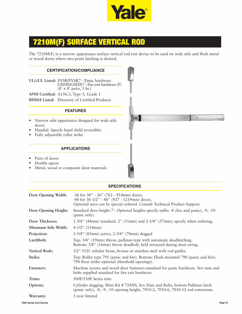
7210M(F) SURFACE VERTICAL ROD
Page 217000 Series Exit Device
The 7210M(F) is a narrow appearance surface vertical rod exit device to be used on wide stile and flush metalor wood doors where two-point latching is desired.
CERTIFICATION/COMPLIANCE
FEATURES
• Narrow stile appearance designed for wide stile doors
• Handed. Specify hand (field reversible)• Fully adjustable roller strike
APPLICATIONS
• Pairs of doors• Double egress• Metal, wood or composite door materials
Door Opening Width: -36 for 30" - 36" (762 - 914mm) doors.-48 for 36-1/2" - 48" (927 - 1219mm) doors.Optional sizes can be special ordered. Consult Technical Product Support.
Door Opening Height: Standard door height 7'. Optional heights specify suffix -8 (fire and panic), -9, -10 (panic only).
Door Thickness: 1-3/4" (44mm) standard. 2" (51mm) and 2-1/4" (57mm); specify when ordering.
Minimum Stile Width: 4-1/2" (114mm)
Projection: 3-1/4" (83mm) active, 2-3/4" (70mm) dogged
Latchbolt: Top: 3/4" (19mm) throw, pullman-type with automatic deadlatching. Bottom: 5/8" (16mm) throw deadbolt, held retracted during door swing.
Vertical Rods: 1/2" O.D. tubular brass, bronze or stainless steel with rod guides.
Strike: Top: Roller type 791 (panic and fire). Bottom: Flush mounted 790 (panic and fire). 794 floor strike optional (threshold openings).
Fasteners: Machine screws and wood door fasteners standard for panic hardware. Sex nuts and bolts supplied standard for fire exit hardware.
Trims: 500F/510F Series trim
Options: Cylinder dogging, Shim Kit # 724NS, Sex Nuts and Bolts, bottom Pullman latch (panic only), -8, -9, -10 opening height, 7010-2, 7010-6, 7010-12 rod extensions.
Warranty: 5-year limited
SPECIFICATIONS
UL/cUL Listed: FVSR/FVSR7 - Panic hardware GXHX/GXHX7 - Fire exit hardware (F)(8' x 8' pairs, 3 hr.)
ANSI Certified: A156.3, Type 5, Grade 1BHMA Listed: Directory of Certified Products

7220M(F) CONCEALED VERTICAL ROD
Page 22 7000 Series Exit Device
The 7220M(F) is a narrow appearance concealed vertical rod exit device for wide stile and flush metal doorsonly and is to be utilized where two-point latching is desired.
CERTIFICATION/COMPLIANCE
FEATURES
• Narrow stile look designed for wide stile doors• Handed. Specify hand (field reversible)• Bottom deadbolt for secure latching• Fully adjustable roller strike
APPLICATIONS
• Pairs of doors• Double egress• Metal doors only
Door Opening Width: -36 for 30" - 36" (762 - 914mm) doors. -48 for 36-1/2" - 48" (927 - 1219mm) doors.Optional sizes can be special ordered. Consult Technical Product Support.
Door Opening Height: Standard door height adjustable to 8'. Optional heights specify suffix -9, -10 (panic only).
Door Thickness: 1-3/4" (44mm) standard. 2" (51mm) and 2-1/4" (57mm); specify when ordering.
Minimum Stile Width: 4-1/2" (114mm)
Projection: 3-1/4" (83mm) active, 2-3/4" (70mm) dogged.
Latchbolt: Top: 3/4" (19mm) throw, Pullman-type with automatic deadlatching. Bottom: 5/8" (16mm) throw deadbolt, held retracted during door swing.
Vertical Rods: 1/2" O.D. telescoping tubular rods.
Strike: Top: Roller strike 791 (panic and fire). Bottom: Flush mounted 790 (panic and fire). 794 floor strike optional (threshold openings)
Fasteners: Machine screws and wood door fasteners standard for panic hardware. Sex nuts and bolts supplied standard for fire exit hardware.
Trims: 500F/510F Series trim
Options: Cylinder dogging, Shim Kit # 723NS, Sex Nuts and Bolts, bottom Pullman latch (panic only), -9, -10 opening height, 7010-2, 7010-6, 7010-12 rod extensions.
Warranty: 5-year limited.
SPECIFICATIONS
UL/cUL Listed: FVSR/FVSR7 - Panic hardware GXHX/GXHX7 - Fire exit hardware (F)(8' x 8' pairs, 3 hr.)
ANSI Certified: A156.3, Type 8, Grade 1BHMA Listed: Directory of Certified Products

7200M TRIM
Page 237000 Series Exit Device
121 & 500F SERIES NARROW ESCUTCHEON TRIM
• Through-bolted. 1-3/4" (44mm) door standard. For doors through 2-1/4" (57mm) or shim mounted devices, specify on order.
• Dimensions: see page 45.• Accepts rim cylinders. For cylinder options,
see page 44.
• Available with all lever and knob designs except CA.See page 45.
• Ordering example: 501F x 605• 1-year limited warranty.
ApplicationsExit Only
Blank PlateNightlatch Passage
Classroom/Storeroom
DummyTrim
PassageDummy
TrimPassage or
DummyClassroom/Storeroom
Classroom/Storeroom
7200M(F)7250M(F) 7210M(F)7220M(F)
500F 121** 501F** 507F 503F* 505F 504F 509F 508F* 506F* 502F*
ANSI – 03 03 16 11/12 02 14 02 14/02 08/09 08/09
*09, 12 and Free-Wheeling 02 achieved with simple trim modification at installation.**Not recommended for use with surface or concealed vertical rod devices.
510F SERIES NARROW ESCUTCHEON TRIM
• Through-bolted: 1-3/4" (44mm) door standard. For doors through 2-1/4" (57mm) or shim mounted devices, specify on order.
• Dimensions: see page 45.
• Accepts rim cylinders. For cylinder options, see page 44.
• 1-year limited warranty.
Applications Dummy Trim Nightlatch PassageClassroom/Storeroom
PassageClassroom/Storeroom
7200M(F), 7250M(F), 7210M(F), 7220M(F)
514F 512F* 517F 513F 519F 518F
ANSI 02 03 16 11/12 15 05/06
Arcadia Augusta Carmel Jefferson
Pinehurst Virginia Brandywine Copenhagen LFVI
JN
PN
CR
CO
AU
BR
MOAR Monroe Pacific Beach
Litchfield CA* Carolina
PB
*CA knob available for 540F Series trim only.
LEVER AND KNOB DESIGNS
*Not recommended for use with surface or concealed vertical rod devices.

7200 SERIES APPLICATIONS
Page 24 7000 Series Exit Device
INTRODUCTION
7200 Series narrow stile exit devices are designed for aluminum openings and are compatible with theaesthetics and functional requirements of contemporary glass doors. The device features lines chosen byleading architects and is available with the proven SquareBolt® exit device for increased security.
APPLICATIONS
Single Door UL Listing Maximum Opening Application
SquareBolt®
7250 Panic 4' x * Surface applied; single-point latching.
Rim
7200 Panic 4' x * Surface applied; single-point latching.
Surface Vertical Rod
7210 Panic 4' x * Surface applied; two-point latching.
Concealed Vertical Rod
7220 Panic 4' x * Rods concealed in door; two-point latching.
Pair of Doors UL Listing Maximum Opening Application
Surface Vertical Rod
7210 x 7210 Panic 8' x *Two independent doors with two-point latching, swinging in thesame direction.
Surface Vertical Rod (Double Egress)
7210 x 7210 Panic 8' x *Two independent doors with two-point latching, swinging inopposite directions.
Concealed Vertical Rod
7220 x 7220 Panic 8' x *Two independent metal doors with two-point latching, swingingin the same direction.
Concealed Vertical Rod (Double Egress)
7220 x 7220 Panic 8' x *Two independent metal doors with two-point latching, swingingin opposite directions.
Pair of Doors withRemovable Mullion
UL Listing Maximum Opening Application
SquareBolt® x SquareBolt®
7250 x 7250 x M300 Panic 8' x 10' Two independent active doors with removable mullion.
Rim x Rim
7200 x 7200 x M300 Panic 8' x 10' Two independent active doors with removable mullion.
*UL does not set a door height limitation on panic applications.

7250 SQUAREBOLT®
Page 257000 Series Exit Device
The unique construction of the SquareBolt exit device offers innovative protection. The patented squarelatchbolt design provides an improved physical barrier over standard Pullman-type rim latchbolts. It locks intoplace and stays there. Credit cards, crowbars, door rattling and shaking are resisted, significantly reducing thethreat of unauthorized entry, especially in applications thatinclude removable mullions. The 7250 SquareBolt is designedfor narrow stile doors.
CERTIFICATION/COMPLIANCE
FEATURES
• Patented SquareBolt security deadbolt (Pat. no. 5,605,362)designed for maximum holding power
• Non-handed for easy installation• Maintains the look of the Yale® 7200 Series
architectural exit devices, allowing for continuity in both design and finish
• Fully adjustable surface mounted 3/8" diameter roller strike complete with positive locking plate and shims
• Used with narrow stile trim
APPLICATIONS
• Single swing narrow stile doors• Pairs of narrow stile doors with removable mullions• Metal and aluminum doors• For panic-rated doors only
Door Opening Width: -36 for 30" - 36" (762 - 914mm) doors.-48 for 36-1/2" - 48" (927 - 1219mm) doors.Optional sizes can be special ordered. Consult Technical Product Support.
Door Thickness: 1-3/4" (44mm) standard. 2" (51mm) and 2-1/4" (57mm); specify when ordering.
Minimum Stile Width: 2" (51mm)
Projection: 3-1/4" (83mm) active, 2-3/4" (70mm) dogged
Deadbolt: Patented 1" (25mm) slide projection bolt with full 3/4" (19mm) projection
Strike: Standard: 759. Optional: 793 (double door applications)
Fasteners: Machine screws standard for panic hardware
Trims: 500F/510F Series trim
Options: Cylinder dogging, Shim Kit # 723NS, Sex Nuts and Bolts
Warranty: 5-year limited
SPECIFICATIONS
UL/cUL Listed: FVSR/FVSR7 - Panic hardware
ANSI Certified: A156.3, Type 4 or 28, Grade 1
BHMA Listed: Directory of Certified Products
U.S. Patent #: 5,605,362
P

7200 RIM
Page 26 7000 Series Exit Device
The 7200 is a narrow stile rim exit device compatible with the aesthetics and functional requirements ofcontemporary doors. The 7200 comes in varied finishes and can be combined with a variety of trims to matchany desired style.
CERTIFICATION/COMPLIANCE
FEATURES
• Designed for narrow stile doors• 3/4" throw deadlocking stainless steel Pullman
latch• Non-handed for easy installation
APPLICATIONS
• Single swing narrow stile doors• Pairs of narrow stile doors with removable mullions• Metal and aluminum doors• For panic-rated doors only
Door Opening Width: -36 for 30" - 36" (762 - 914mm) doors-48 for 36-1/2" - 48" (927 - 1219mm) doorsOptional sizes can be special ordered. Consult Technical Product Support.
Door Thickness: 1-3/4" (44mm) standard. 2" (51mm) and 2-1/4" (57mm); specify when ordering.
Minimum Stile Width: 2" (51mm).
Projection: 3-1/4" (83mm) active, 2-3/4" (70mm) dogged.
Latchbolt: 3/4" (19mm) deadlocking stainless steel Pullman type.
Strike: Standard: 759. Optional: 793 (double door applications).
Fasteners: Machine screws standard for panic hardware.
Trims: 500F/510F Series trim.
Options Cylinder dogging, Shim Kit # 723NS, Sex Nuts and Bolts.
Warranty: 5-year limited.
SPECIFICATIONS
UL/cUL Listed: FVSR/FVSR7 - Panic hardware ANSI Certified: A156.3, Type 4, Grade 1
BHMA Listed: Directory of Certified Products

7210 SURFACE VERTICAL ROD
Page 277000 Series Exit Device
The 7210 is a narrow stile surface vertical rod exit device to be used on narrow stile, aluminum and metaldoors where two-point latching is desired.
FEATURES
• Designed for narrow stile doors• Handed. Specify hand (field reversible)• Bottom deadbolt for secure latching• Fully adjustable roller strike
APPLICATIONS
• Pairs of narrow stile doors• Metal and aluminum doors• For panic-rated doors only
Door Opening Width: -36 for 30" - 36" (762 - 914mm) doors-48 for 36-1/2" - 48" (927 - 1219mm) doorsOptional sizes can be special ordered. Consult Technical Product Support.
Door Opening Height: Standard door height 7'. Optional heights specify suffix -8, -9, -10.
Door Thickness: 1-3/4" (44mm) standard. 2" (51mm) and 2-1/4" (57mm); specify when ordering.
Minimum Stile Width: 2" (51mm).
Projection: 3-1/4" (83mm) active, 2-3/4" (70mm) dogged.
Latchbolt: Top: 3/4" (19mm) stainless steel throw, Pullman-type with automatic deadlatching.Bottom: 5/8" (16mm) throw deadbolt, held retracted during door swing.
Vertical Rods: 1/2" (13mm) O.D. tubular brass, bronze or stainless steel with rod guides.
Strike Top: roller type 791. Bottom: flush mounted 790. 794 floor strike optional (threshold openings).
Fasteners: Machine screws standard for panic hardware.
Trims: 500F/510F Series trim.
Options: Cylinder dogging, Shim Kit # 724NS, Sex Nuts and Bolts, -8, -9, -10 opening height, 7010-2, 7010-6, 7010-12 rod extensions, bottom Pullman latch.
Warranty: 5-year limited.
SPECIFICATIONS
CERTIFICATION/COMPLIANCE
UL/cUL Listed: FVSR/FVSR7 - Panic hardware
ANSI Certified: A156.3 Type 5, Grade 1
BHMA Listed: Directory of Certified Products

7220 CONCEALED VERTICAL ROD
Page 28 7000 Series Exit Device
The 7220 is a narrow stile concealed vertical rod exit device to be used on narrow stile, aluminum and metaldoors where two-point latching is desired.
FEATURES
• Designed for narrow stile doors• Handed. Specify hand (field reversible)• Bottom deadbolt for secure latching• Fully adjustable roller strike
APPLICATIONS
• Pairs of narrow stile doors• Metal and aluminum doors• For panic-rated doors only
Door Opening Width: -36 for 30" - 36" (762 - 914mm) doors-48 for 36-1/2" - 48" (927 - 1219mm) doorsOptional sizes can be special ordered. Consult Technical Product Support.
Door Opening Height: Standard door height adjustable to 8'. Optional heights specify suffix -9, -10
Door Thickness: 1-3/4" (44mm) standard. 2" (51mm) and 2-1/4" (57mm); specify when ordering.
Minimum Stile Width: 2" (51mm)
Projection: 3-1/4" (83mm) active, 2-3/4" (70mm) dogged
Latchbolt: Top: 3/4" (19mm) throw, pullman-type with automatic deadlatchingBottom: 5/8" (16mm) throw deadbolt, held retracted during door swing
Vertical Rods: 1/2" (13mm) O.D. telescoping tubular rods
Strike: Top: roller type 791. Bottom: flush mounted 790. 794 floor strike optional (threshold openings)
Fasteners: Machine screws and wood door fasteners standard for panic devices.
Trims: 500F/510F Series trim
Options: Cylinder dogging, Shim Kit # 723NS, Sex Nuts and Bolts, -9. -10 opening height, 7010-2, 7010-6, 7010-12 rod extensions, bottom Pullman latch.
Warranty: 5-year limited
SPECIFICATIONS
CERTIFICATION/COMPLIANCE
UL/cUL Listed: FVSR/FVSR7 - Panic hardware
ANSI Certified: A156.3 Type 5, Grade 1
BHMA Listed: Directory of Certified Products

7200 SERIES TRIM
Page 297000 Series Exit Device
121 & 500F SERIES NARROW ESCUTCHEON TRIM
• Through-bolted. 1-3/4" (44mm) door standard. For doors through 2-1/4" (57mm) or shim mounted devices, specify on order.
• Dimensions: see page 45.• Accepts rim cylinders. For cylinder options,
see page 44.
• Available with all lever and knob designs except CA.See page 45.
• Ordering example: 508F x 605• 1-year limited warranty.
ApplicationsExit Only
Blank PlateNightlatch Passage
Classroom/Storeroom
DummyTrim
PassageDummy
TrimPassage or
DummyClassroom/Storeroom
Classroom/Storeroom
7200 721072207250
500F 121** 501F** 507F 503F* 505F 504F 509F 508F* 506F* 502F*
ANSI – 03 03 16 11/12 02 14 02 14/02 08/09 08/09
*09, 12 and Free-Wheeling 02 achieved with simple trim modification at installation.*Not recommended for use with surface or concealed vertical rod devices.
510F SERIES NARROW ESCUTCHEON TRIM
• Through-bolted: 1-3/4" (44mm) door standard. For doors through 2-1/4" (57mm) or shim mounted devices, specify on order.
• Dimensions: see page 45.
• Accepts rim cylinders. For cylinder options, see page 44.
• Ordering example: 519F x 606• 1-year limited warranty.
Applications Dummy Trim Nightlatch PassageClassroom/Storeroom
PassageClassroom/Storeroom
7200, 7210, 7220, 7250
514F 512F* 517F 513F 519F 518F
ANSI 02 03 16 11/12 15 05/06
Arcadia Augusta Carmel Jefferson
Pinehurst Virginia Brandywine Copenhagen LFVI
JN
PN
CR
CO
AU
BR
MOAR Monroe Pacific Beach
Litchfield CA* Carolina
PB
*CA knob available for 540F Series trim only.
LEVER AND KNOB DESIGNS
*Not recommended for use with surface or concealed vertical rod devices.

ELECTRIFIED EXIT DEVICES
Page 30 7000 Series Exit Device
The Yale® 7000 Series exit devices offer a complete range of electrical options. A continuity in appearance,security and functions with the 7000 Series mechanical exit device is maintained. These electrified exitdevices may be integrated into the monitoring security and alarm systems of most buildings.
Note: The following options cannot be orderedtogether: 1) P, G, or D 2) B or A 3) D, B or A4) P, S and A on surface vertical rod
Model # Exit Device Description A B D G O P S SAFE SECURE 690F 691F
7100 (F) Rim Exit Device (Std.) x x x x x x x x x
7110 (F) Surface Vertical Rod (Std.) x x x x x x x x
7120 (F) Concealed Vertical Rod (Std.) x x x x x x x
7130 (F) Mortise Exit Device (Std.) x x x x x x x x x
7150 (F) Rim SquareBolt® Device (Std.) x x x x x x x x x
7160 (F90) Concealed Vertical Rod (Std.) x x x x x x x
7170 (F90) Surface Vertical Rod (Std.) x x x x x x x x
7200 (M)(F) Rim Exit Device (Narrow) x x x x x x
7250 (M)(F) Rim SquareBolt® Device (Narrow) x x x x x x
7210 (M)(F) Surface Vertical Rod (Narrow) x x x x x
7220 (M)(F) Concealed Vertical Rod (Narrow) x x x x x x
ELECTRIFIED OPTIONS CHART FOR YALE® EXIT DEVICES
ELECTRIFIED HARDWARE OPTION DESCRIPTONS FOR YALE® EXIT DEVICES
A Alarm Option
B Touchbar Monitor
D SecureX® (Delayed Egress)
G Electric Dogging
O Trim Monitor
P Latch Retraction
S Bolt Monitor
SAFE* Fail Safe Operation
SECURE* Fail Secure Operation
690F Fail Safe Electrified Trim
691F Fail Secure Electrified Trim
*Lever function trims only
What normally took an hour or more to connect now takes minutes.Yale electrified exit devices and trims are equipped with ElectroLynx™
connectors. As a standard feature, these “plug & play” connectors linkpower from the incoming source to electrified locking products,including hinges, locks, exit devices, magnetic holders and strikes.
Note: Electrified door hardware with ElectoLynx™ connectors require a compatiblenumber of lead wires attached to the door hinge.

ELECTRIFIED EXIT DEVICES
Page 317000 Series Exit Device
OperationAllows the latchbolt to be retracted electrically formomentary or maintained periods of time from aremote location. Device bolts remain retracted(push/pull) for as long as the device is energized.Removal of power returns the device to the life safety,self-latching mechanical mode. Easy interface withcentral or local fire alarm systems, automatic dooroperators, and access control systems. Allows freeegress at all times. Manual hex key dogging standardon non-rated devices.
Electrical SpecificationsSolenoid Assembly• Continuous duty• 5.5 volt solenoid with a 36-volt holding magnet
(.172 amp seated)• 9 amp inrush• Requires a 4-wire minimum pivot or hinge to
transfer power from frame to door.• Requires the 781N controller for operation
(USING ANY OTHER POWER SUPPLY VOIDS THE WARRANTY OF THE DEVICE.)
ListingsUL/cUL listed for panic and fire exit hardware.Fire-rated devices must be wired into an automaticfire alarm system.
ApplicationsRim: 7100(F), 7200, 7200M(F)SquareBolt®: 7150(F), 7250, 7250M(F)SVR: 7110(F), 7170(F90), 7210, 7210M(F)CVR: 7120(F), 7160(F90), 7220, 7220M(F)Mortise: 7130(F)
OrderingSuffix “P” to the Model Number. Ex: 7100P.
OperationProvides continuous latch retraction and pushpaddogging simultaneously. When power is applied to thedevice, depressing the pushpad will retract thelatchbolt and continuously hold down the pushpad inthe unlock position for push/pull operation. Removalor interruption of power will release the pushpad andthe latchbolt will extend and secure the opening. Foruse in areas that require quiet door operation.Exit device allows free egress at all times.
Electrical Specifications2 Holding Magnets• .35 amps @ 24VDC
Requires a 2-wire pivot or hinge and a standard24VDC regulated and filtered power source(Recommended Folger Adam® MPS10 powersupplies)
ListingsUL/cUL listed for panic and fire exit hardware.Fire-rated devices must be wired into an automaticfire alarm system.
ApplicationsRim: 7100(F), 7200, 7200M(F)SquareBolt: 7150(F), 7250, 7250M(F)SVR: 7110(F), 7170(F90), 7210, 7210M(F)CVR: 7120(F), 7160(F90), 7220, 7220M(F)Mortise: 7130(F)
OrderingSuffix “G” to the Model Number. Ex: 7150G.
OperationAllows the outside trim to lock or unlock electricallyfrom a remote location. Exit device allows free egressat all times.
Fail Safe devices are commonly used in stair towers orlocations that require the trim to unlock when poweris removed or during fire alarm activation.
Fail Secure devices are used to secure openings andare usually integrated into the building securitysystem to allow access control. Fail Secure trimsremain locked when power is removed.
Electrical SpecificationsSolenoid• .35 amps @ 24VDC only (12 volt not available)• Continuous duty• Requires a 2-wire pivot or hinge and a standard
24VDC regulated and filtered power source (Recommended Folger Adam® MPS10 power supplies)
ListingsUL/cUL listed for panic and fire exit hardware.
ApplicationsMortise: 7130(F) - lever functions only
Ordering“Safe” – Maintains the outside trim in a locked state when energized. Removal of power unlocks outsidetrim.“Secure” – Unlocks the outside trim when energized.Remains locked when power is removed.
Suffix “SAFE” or “SECURE” to the Model Number. Ex: 7130 x L5 x Safe.
ELECTRIC LATCH RETRACTION “P”
ELECTRIC DOGGING “G”
MORTISE DEVICE TRIM CONTROL “SAFE/SECURE”

SECUREX® DELAYED EGRESS
Page 32 7000 Series Exit Device
SECUREX™ “D”
The SecureX® delayed egress exitdevice provides additional securityand safety in a strong line of panicand fire hardware. SecureX is anelectromechanical device used tosecure interior or exterioropenings.
An exit door is normally closedand latched. The delayed egressdevice secures the door in thelocked mode with the Red LEDindicating locked mode status.Depressing the pushpad for lessthan three seconds will cause thedevice to beep without initiatingthe alarm. Depressing the pushpadfor three seconds or longer willinitiate an irreversible local audiblebeeping tone and a visual amberindicator. The person depressingthe pushpad is denied egress for 15or 30 seconds while alarm signalsunauthorized egress. After thefactory-set delay time (15 or 30seconds), the device releases foregress, the LED changes to Greenand the beep changes to a steadytone which continues to alarmuntil reset. The remote monitoringcontact outputs can be used toalert security personnel. Note: The 15-second time delay isstandard. (Optional 30-seconds may beaccepted by local jurisdiction.)
• For use on hollow metal interioror exterior doors.
• Available for 7100(F), 7200M(F)and 7200 Series rim, SquareBolt®,surface vertical rod, concealed vertical rod and mortise panic and fire-rated exit devices. For surface vertical rod exit devices, rod and latch guards (provided by other) must be used.
• Complies with NFPA 101 “CodeFor Safety To Life From Buildings And Structures” by National Fire Protection Association.
• BOCA options available to comply with National Building Code requirements. BOCA option is not suitable for installationsin accordance with NFPA 101.
• 1-3/4" door thickness standard; 2" and 2-1/4" optional; specify when ordering.
• Standard 36" device fits doors 35"-36" Device cannot be cut less than 35".
• Option -48 fits doors 41"-48". Devices cannot be cut less than 41".
Key Switch Operation:• Normal: The system is armed
by applying power to the device (solid Red LED). Depressing the pushpad for more than the nuisance delay time starts the exit delay cycle.
• Bypass: Turning the key switch clockwise to the bypass position allows immediate egress without alarming. The bar functions as a standard exitdevice (Red LED flashes slowly).
• Reset/Delay: Used to reset device after the factory-set 15 or 30-second delay cycle hastimed out. Rearm: If the deviceis armed, turning the key counterclockwise to the reset mode will release the device without alarm for egressand will rearm after 10 seconds(Red LED flashes quickly).
Local Visual Status Indicator:• RED: The exit device is secure
and the delayed egress circuitryis energized.
• AMBER: The egress cycle has started, indicated by an irreversible local audible beeping tone.
• GREEN: The exit device is in alarm and has released.
Nuisance Delay Time:• Depressing the pushpad for less
than three seconds sounds an audible beep without activatingthe irreversible alarm sequence.(Immediate alarm can be selected by removing a jumper on the control board.)
Internal Alarm Siren:• When armed, depressing the
pushpad initiates the internal 85db alarm siren.
Remote Control Inputs:• Remote Reset: Accepts a
momentary contact (keyswitch,pushbutton, etc) to reset the unit during alarm or allows momentary egress (10 seconds) when the unit is armed.
• Remote Bypass: Accepts a momentary contact to put the unit in a maintained bypass operation. The exit device functions as a standard device.
Alarm Outputs:• Two sets of normally open and
normally closed contacts. Contacts change only during alarm status. One set of contactschanges when device delay cycle has started (Alarm). One set of contacts changes when device has released (Secure).
Door Sign:• Door sign per code included.
Power Supply:A regulated and filtered powersupply with a fire alarm interfaceis required. 1 Amp minimum @24VDC per device. Special optionswill require more amperage.Consult factory. Recommend:Folger Adam® FA BPS Series.
Power Transfer:Allows the power cable to makethe transition from frame to doorwithout pinching or removal ofinsulation.
SecureX may be used with any7000 series trim. The 600F Seriesheavy-duty trim is recommended.
OPERATION
STANDARD FEATURES
REQUIRED ACCESSORIES
TRIM
APPLICATIONS

SECUREX® DELAYED EGRESS
Page 337000 Series Exit Device
OPTIONS
Security Package “H”:• An internal door position switch
that gives added security to the opening and is recommended. When using this option the alarm will sound if the door is not closed and latched when arming the device or if the door is forced open when the device is armed.
• To order, suffix “H”.• NOTE: Available for 7100(F)
Rim and 7150(F) SquareBolt®
devices only.Latchbolt Monitor “S”:• Used to monitor the positions
of the latchbolt or vertical rods(SPDT switch).
• To order, suffix “S”.Trim Monitor Switch “O”:• Used when outside trim is
desired. This switch will allow Bypass (disarms device) when the trim is used for ingress. Thedevice will need to be reset upon entry by means of the keyswitch on the device or a remote switch.
• To order, suffix “O”.• NOTE: If the security package
or external DPS is not used, standard trim will allow entry without affecting the device in an armed mode. The device will only be affected when the pushpad is depressed.
NFPA 101 Requirements:15- & 30-Second Delay• Upon depressing the pushpad
for 3 seconds, SecureX® will sound an audible beeping tone and allow the door to be opened after 15 (or 30) seconds. The tone will then change to a continuous alarm until reset. Resetting of the alarm and re-arming of the device is accomplished by manual means only.
• To order, specify NFPA 15-second or NFPA 30-second.
• Purchase orders that do not have an option noted will defaultto the NFPA 15-second delay.
• NOTE: Where approved by theauthority having jurisdiction, a delay not exceeding 30 secondsshall be permitted.
BOCA Requirements:15- & 30-Second Delay• Upon depressing the pushpad
for 1 second, SecureX will sound an audible beeping tone and allow the door to be opened within 15 (or 30) seconds. The tone will then change to a continuous alarm until reset. Resetting of the alarm and re-arming of the device occurs automatically once the door has been returned to the closed position for 30 seconds. The 30-second re-arming timer will re-start if the pushpad is depressed or thedoor is re-opened before actualre-arming of the device occurs. A DPS (Door Position Switch) is required for the BOCA option.
• To order specify BOCA 15-second or BOCA 30-second.
• Purchase orders that do not havean option noted will default to the NFPA 15-second delay.
• NOTE: An increase in the egress delay to 30 seconds shallnot be permitted except as approved by the authority having jurisdiction.
Electric Trim Control - “SAFE” or“SECURE”:• The mortise delayed egress exit
device can be ordered with fail safe or fail secure outside trim operation. In a fire condition the fail safe trim will release forentry. When access control is used the fail secure trim allows entry by means of a remote card reader, keyswitch, pushbutton, etc.
• To order, suffix “Safe” or "Secure".
• NOTE: The trim will open the door without affecting the devicein an armed condition, if a door position switch is not used.
See 690/691 electric trim for rimand vertical rod devices.
7000 Series exit devices and heavyduty trim carry a 5-year limitedwarranty. Electronic componentsand utility trim carry a 1-year limited warranty.
Specifications:• Input Voltage 24VDC (+/- 10%)
Power Consumption:• Standard Device: 500 mA• Device with Security Package:
750 mA• Device with Electric Mortise
Trim Control: 1.25 Amps
UL/cUL Listed: FUKD/FUKD7 -Controlled Exit Panic DevicesFWAX/FWAX7 - Special LockingArrangementsGXHX/GXHX7 - Fire ExitHardwareANSI Certified: A156.3 & A156.24BHMA Listed: Directory ofCertified Products
• Suffix “D” after device. Example: 7150FD
WARRANTY
CERTIFICATIONS & LISTNGS
SPECIFICATION
ORDERING INFORMATION
CYLINDERS
Utilizes a 1-1/8" mortise cylinderwith a 2160 cam. Cylinder notincluded unless specified. See page44.
FINISHES
BHMA 605, 606, 611, 612, 613,625, 626, 629, 630.

ALARM KIT & ELECTRIC TRIM
Page 34 7000 Series Exit Device
Activation: Alarm is armed byturning key clockwise. Lowaudible chirp indicates alarm hasbeen activated. Alarm will soundwhen the exit device pushpad isdepressed. Factory preset forstandard alarm mode whichautomatically resets after 5minutes.
Continuous Alarm Mode: Alarmsounds continuous when the exitdevice pushpad is depressed.Alarm must be manually reset bykeyswitch. (This feature is selectedby a switch on the circuit board.)
Low Battery Warning: Audiblechirp.
Nuisance Alarm: Factory presetfor instant alarm. Selectablefeature for alarm to sound whenpushpad is depressed for morethan 2 seconds. (This feature isselected by a switch on the circuitboard.)
Arming Delay/Authorized Egress:10-second delay (after arming) permitting egress (by turning keyclockwise).
Alarm Shunt: Ingress shunt alarminput for devices with bolt status(S) monitor. NOTE: “S” includedwith SVR devices.
Power Requirements: One 9-VoltBattery (included).
Loudness: 90db @ 10 feet.
Arm/Disarm: Uses one 1-1/8"straight cam mortise cylinder.Clockwise turn arms the alarm,counter clockwise turn disarms orsilences the alarm.
Device Status: A Red LEDindicator will illuminate every 30seconds when the alarm is armed.
Tamper Resistant: Built-in safetymonitor sounds alarm whentampering occurs.
Warning Decal: “EMERGENCYEXIT - ALARM WILL SOUND”
Applications: Rim: 7100(F),7200, 7200M(F); SquareBolt®:7150(F), 7250, 7250M(F); SVR:7110(F), 7170(F90), 7210,7210M(F); CVR: 7120(F),7160(F90), 7220, 7220M(F);Mortise: 7130(F)
Kit: Available in kit form for fieldretrofit.
Bar Length: Available for 36"- 48"devices only. May not be used onbars less than 36".• Standard 36" device fits doors
35"-36" Device cannot be cut less than 35".
• Option -48 fits doors 41"– 48".Devices cannot be cut less than 41".
How to Order: Specify 7116 foralarm kit. Suffix -“A” whenordering with device. Ex: 7150-A.
NOTE: The 7116 alarm kitcannot be retrofitted in the field tothe 7110(F), 7170(F), 7210 or7210M(F) surface vertical rod exitdevices. This option is available asa factory order only for thesedevices. Any attempt to retrofitthe 7116 alarm kit with thesesurface vertical rod exit deviceswill void the warranties for theseproducts.
The electrified 600 Series heavy-duty trim provides electric lockingand unlocking of trim. Ideal fordoor control where increasedsecurity is necessary at all times,while meeting life safety codes.
Electric trim is ideal for manyapplications, including stairwelltowers, high-security areas,schools, hospitals, and factories.
Functions690F Trim - Fail Safe• Lever is locked when power is
on (Free-Wheeling)• Power off allows entry from trim• Inside device is always active for
egress• Mechanical key override
(09 Function - Key allows leverto retract latchbolt. Key canonly be removed in lockedposition)
691F Trim - Fail Secure• Lever is locked when power is
off (Free-Wheeling)• Power on allows lever activation
for entry• Inside device is always active for
egress• Mechanical key override
(09 Function - Key allows leverto retract latchbolt. Key canonly be removed in lockedposition.)
Features• Utilizes 600 Series heavy-duty trim• Accepts all standard lever designs• Plug connector with 4' wire lead
(Exit device is used as wireraceway, not door)
• Key Override - Requires rimcylinder (sold separately)
Applications• 7100(F) Rim Device• 7150(F) SquareBolt®
• 7110(F), 7170(F90) SurfaceVertical Rod
Electrical Specifications• 330 mA @ 24 VoltsSM - Security Monitor Switch• 4 AMP @ 250VACVoltage: 24 VAC/VDC onlyFABPS Series Folger Adam® power suppliesrecommended.
Options• SM - Security Monitor. A
SPDT switch that monitors theposition of the solenoid (lockand unlock status).
• EX - Trim gasket for exteriorapplications.
ALARM KIT “A”
ELECTRIC TRIM
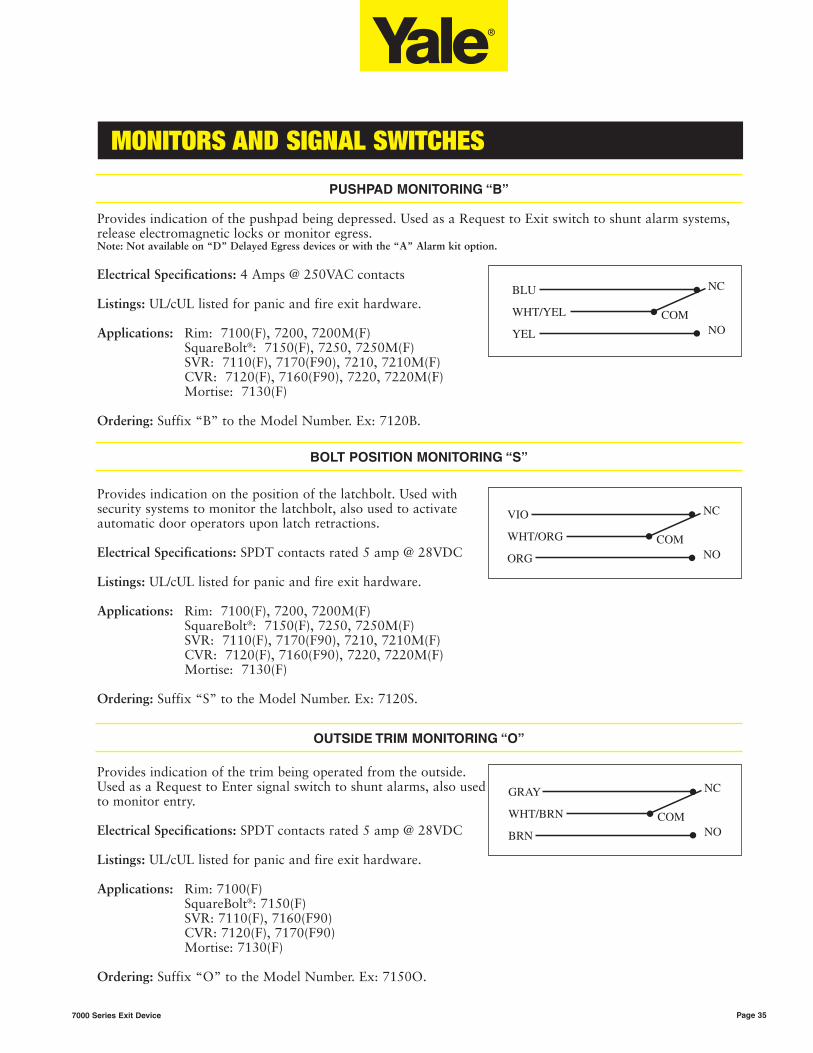
PUSHPAD MONITORING “B”
Provides indication of the pushpad being depressed. Used as a Request to Exit switch to shunt alarm systems,release electromagnetic locks or monitor egress.Note: Not available on “D” Delayed Egress devices or with the “A” Alarm kit option.
Electrical Specifications: 4 Amps @ 250VAC contacts
Listings: UL/cUL listed for panic and fire exit hardware.
Applications: Rim: 7100(F), 7200, 7200M(F)SquareBolt®: 7150(F), 7250, 7250M(F)SVR: 7110(F), 7170(F90), 7210, 7210M(F)CVR: 7120(F), 7160(F90), 7220, 7220M(F)Mortise: 7130(F)
Ordering: Suffix “B” to the Model Number. Ex: 7120B.
Provides indication on the position of the latchbolt. Used withsecurity systems to monitor the latchbolt, also used to activateautomatic door operators upon latch retractions.
Electrical Specifications: SPDT contacts rated 5 amp @ 28VDC
Listings: UL/cUL listed for panic and fire exit hardware.
Applications: Rim: 7100(F), 7200, 7200M(F)SquareBolt®: 7150(F), 7250, 7250M(F)SVR: 7110(F), 7170(F90), 7210, 7210M(F)CVR: 7120(F), 7160(F90), 7220, 7220M(F)Mortise: 7130(F)
Ordering: Suffix “S” to the Model Number. Ex: 7120S.
Provides indication of the trim being operated from the outside.Used as a Request to Enter signal switch to shunt alarms, also usedto monitor entry.
Electrical Specifications: SPDT contacts rated 5 amp @ 28VDC
Listings: UL/cUL listed for panic and fire exit hardware.
Applications: Rim: 7100(F)SquareBolt®: 7150(F)SVR: 7110(F), 7160(F90)CVR: 7120(F), 7170(F90)Mortise: 7130(F)
Ordering: Suffix “O” to the Model Number. Ex: 7150O.
MONITORS AND SIGNAL SWITCHES
Page 357000 Series Exit Device
BOLT POSITION MONITORING “S”
OUTSIDE TRIM MONITORING “O”

ELECTRIFIED EXIT DEVICE ACCESSORIES
Page 36 7000 Series Exit Device
OperationDesigned to control one or two electric latchretraction “P” exit devices. Equipped with two 20-second timers which can operate the exit devicestogether or independently. Requires a momentary ortimed, dry contact input and can be interfaced withaccess control systems, automatic door operators,“blow open” type scenarios and has provisions forN/C fire alarm systems.Note: The 781N is required for use with the “P” latch retractionoption. Using any other power supply with the “P” option voidsthe warranty of the device.
Features• 2 control inputs. Accepts normally closed dry
contacts for device activation from a key switch, push button, access control or fire alarm system.
• 2 normally open control outputs for automatic door operators
• 2 “P” device outputs• Fire Alarm Interface input• 12VDC output for audible or LEDS .25 AMP • 24VDC output for audible or LEDS .25 AMP
WiringUp to 40 feet: 16 AWG wireUp to 60 feet: 14 AWG wireUp to 100 feet: 12 AWG wire
Electrical Specifications• 120VAC or 120VAC 60 Hz Power input• 9 amp inrush for 100 milliseconds
ListingsListed as an Exit Device Control Unit to UL 294requirements.
Applications“P” Electric Latch Retraction Option
Ordering781N Controller
781N POWER CONTROL
OperationPower supplies are designed to provide reliablefiltered and regulated power for long life to a variety of electrified hardwarecomponents. Recommended for the Safe, Secure, G and D optionsand 690/691 electric trim. Consult the Folger Adam®
catalog for additional information on options andaccessories.
Product Features• Individual output circuit breakers• Regulated and filtered fuse protected outputs • LEDs monitor zone status (voltage or no voltage)• Slide switches connect or disconnect load from
power (Not available on 1 Amp supplies)• Internal Back-Up Battery charging circuit • Rugged steel enclosure• Fire alarm interface
Listings• UL CLASS 2
Applications (use with):• D – Delayed Egress• G – Electric Dogging• Safe – Fail Safe mortise device trim control• Secure – Fail Secure mortise device trim control• 690/691 – Electric Trim
OrderingEx: FABPS-24-4
Model Input Output Application
FABPS-24-1 120 VAC 1 amp @ 24 VDC 1 “D”
FABPS-24-2 120 VAC 2 amp @ 24 VDC2 “D” or 1 “D” with
Safe or Secure
FABPS-24-4 120 VAC 4 amp @ 24 VDC4 “D” or 3 “D” with
Safe or Secure
FABPS POWER SUPPLY BY FOLGER ADAM®
Consult factory for additional power supply applications.
SECUREX® POWER SUPPLY REQUIREMENTS

ELECTRIFIED EXIT DEVICE ACCESSORIES
Page 377000 Series Exit Device
Patented electric power transfer is concealed in thedoor and frame edges, maintaining aesthetics andsecurity. A unique advantage is that the EPT/EPTLaccepts interior wire cables up to .25" (6mm) thickand protects the wires with a flexible steel shield.Suitable for applications where a relatively largecurrent is required, and works with doors hung withbutt hinges, continuous hinges and pivots.Note: It will not function on a center pivot door due to the largegap between the door and frame edges when the door is open.
To order, specify:EPT: Concealed Transfer for up to 120° swing doorsEPTL: Concealed Transfer for over 120° swing doors
EPT & EPTL ACCESSORIES BY FOLGER ADAM®
The following Folger Adam accessories can beintegrated into an electronic package using 7000series electrified exit devices and trims. Theseaccessories must be ordered through Folger Adam.Reference the Folger Adam catalog for additionaltechnical and ordering information.
Power Transfer Hinges 4-1/2 x 4-1/2 (McKinney)PTH-2: 2 conductor PTH-4: 4 conductor PTH-10: 10 conductorElectrical Specifications: 22 AWG, 5A @ 24V AC/DCFinishes: 605, 612, 613, 625, 626
FATSB-C Door Cord 18"(Less Wires)
Annunciators for SecureX®
101-1A: Remote or local singledoor annunciator with alarm andtricolor LED
101AK: Remote or local single door annunciatorwith 2-function key switch for reset and bypass, andaudible alarm mute button with tri-color LED (2gang). Accepts standard 1-1/8" to 1-1/4" mortisecylinder.
Folger Adam® product must be ordered through Folger Adam. Consult Folger Adam catalog for additional information.
REAR VIEW
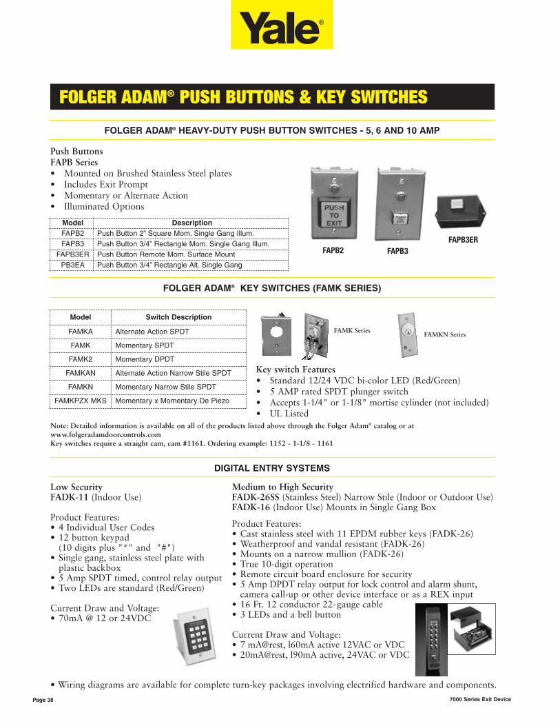
FAPB3ER
FAMK SeriesFAMKN Series
FOLGER ADAM® PUSH BUTTONS & KEY SWITCHES
Page 38 7000 Series Exit Device
Model DescriptionFAPB2 Push Button 2” Square Mom. Single Gang Illum.FAPB3 Push Button 3/4” Rectangle Mom. Single Gang Illum.
FAPB3ER Push Button Remote Mom. Surface MountPB3EA Push Button 3/4” Rectangle Alt. Single Gang
• Wiring diagrams are available for complete turn-key packages involving electrified hardware and components.
Model Switch Description
FAMKA Alternate Action SPDT
FAMK Momentary SPDT
FAMK2 Momentary DPDT
FAMKAN Alternate Action Narrow Stile SPDT
FAMKN Momentary Narrow Stile SPDT
FAMKPZX MKS Momentary x Momentary De Piezo
Note: Detailed information is available on all of the products listed above through the Folger Adam® catalog or at www.folgeradamdoorcontrols.comKey switches require a straight cam, cam #1161. Ordering example: 1152 - 1-1/8 - 1161
FOLGER ADAM® KEY SWITCHES (FAMK SERIES)
FOLGER ADAM® HEAVY-DUTY PUSH BUTTON SWITCHES - 5, 6 AND 10 AMP
Key switch Features• Standard 12/24 VDC bi-color LED (Red/Green)• 5 AMP rated SPDT plunger switch• Accepts 1-1/4" or 1-1/8" mortise cylinder (not included)• UL Listed
Low Security FADK-11 (Indoor Use)
Product Features:• 4 Individual User Codes • 12 button keypad
(10 digits plus "*" and "#") • Single gang, stainless steel plate with
plastic backbox • 5 Amp SPDT timed, control relay output• Two LEDs are standard (Red/Green)
Current Draw and Voltage:• 70mA @ 12 or 24VDC
Push ButtonsFAPB Series• Mounted on Brushed Stainless Steel plates• Includes Exit Prompt• Momentary or Alternate Action• Illuminated Options
Medium to High Security FADK-26SS (Stainless Steel) Narrow Stile (Indoor or Outdoor Use)FADK-16 (Indoor Use) Mounts in Single Gang Box
Product Features:• Cast stainless steel with 11 EPDM rubber keys (FADK-26) • Weatherproof and vandal resistant (FADK-26) • Mounts on a narrow mullion (FADK-26) • True 10-digit operation • Remote circuit board enclosure for security • 5 Amp DPDT relay output for lock control and alarm shunt,
camera call-up or other device interface or as a REX input • 16 Ft. 12 conductor 22-gauge cable • 3 LEDs and a bell button
Current Draw and Voltage:• 7 mA@rest, l60mA active 12VAC or VDC• 20mA@rest, l90mA active, 24VAC or VDC
DIGITAL ENTRY SYSTEMS
FAPB2 FAPB3
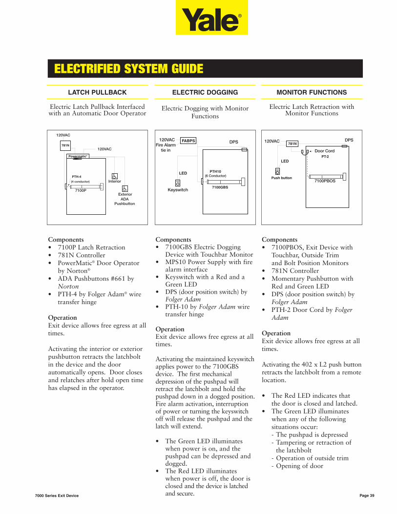
ELECTRIFIED SYSTEM GUIDE
Page 397000 Series Exit Device
FABPS
LED
Components• 7100P Latch Retraction• 781N Controller• PowerMatic® Door Operator
by Norton®
• ADA Pushbuttons #661 by Norton
• PTH-4 by Folger Adam® wire transfer hinge
OperationExit device allows free egress at alltimes.
Activating the interior or exteriorpushbutton retracts the latchboltin the device and the doorautomatically opens. Door closesand relatches after hold open timehas elapsed in the operator.
Components• 7100GBS Electric Dogging
Device with Touchbar Monitor• MPS10 Power Supply with fire
alarm interface• Keyswitch with a Red and a
Green LED• DPS (door position switch) by
Folger Adam• PTH-10 by Folger Adam wire
transfer hinge
OperationExit device allows free egress at alltimes.
Activating the maintained keyswitchapplies power to the 7100GBSdevice. The first mechanicaldepression of the pushpad willretract the latchbolt and hold thepushpad down in a dogged position.Fire alarm activation, interruptionof power or turning the keyswitchoff will release the pushpad and thelatch will extend.
• The Green LED illuminates when power is on, and the pushpad can be depressed and dogged.
• The Red LED illuminates when power is off, the door is closed and the device is latched and secure.
LATCH PULLBACK
Electric Latch Pullback Interfacedwith an Automatic Door Operator
ELECTRIC DOGGING
Electric Dogging with MonitorFunctions
MONITOR FUNCTIONS
Electric Latch Retraction withMonitor Functions
Components• 7100PBOS, Exit Device with
Touchbar, Outside Trim and Bolt Position Monitors
• 781N Controller• Momentary Pushbutton with
Red and Green LED• DPS (door position switch) by
Folger Adam• PTH-2 Door Cord by Folger
Adam
OperationExit device allows free egress at alltimes.
Activating the 402 x L2 push buttonretracts the latchbolt from a remotelocation.
• The Red LED indicates that the door is closed and latched.
• The Green LED illuminates when any of the following situations occur:- The pushpad is depressed- Tampering or retraction of
the latchbolt- Operation of outside trim- Opening of door
781N
PT-2
Push button
LED

ELECTRIFIED SYSTEM GUIDE
Page 40 7000 Series Exit Device
DK11Keypad
FABPS
Components• 7100 - PB627F Nightlatch
Trim - Yale®
• S Bolt Position Monitor Switch • B Pushpad Monitor Switch • O Trim Monitor Switch • Door Position Switch - Folger
Adam®
• PTH-10 Power Transfer Hinge - Folger Adam
• Surface Door Closer - Yale
OperationOperation of the 7100 Exit Devicewith the S, B, O and ASSW-104Acan be used together orindividually to sound an alarm,shunt an alarm, monitor the door’ssecurity or as a “Request to Exit”in conjunction a magnetic lock.
Components• 691F Electrified Trim - Yale• 7100 Rim Exit Device - Yale• Digital Keypad by Folger Adam• PTH-4 Electrified Hinge by
Folger Adam• MPS10 Power Supply by
Folger Adam
OperationOperation of the Digital Keypadwill allow keyless entry from thenon-protected side of the opening.When a valid code is entered intothe keypad, voltage will be appliedto the trim, making the lever activeand allowing ingress. Free exit isallowed by using the exit devicefrom the protected side of thedoor.
MONITOR FUNCTIONS
Rim Exit Device with High Security Application
ELECTRIC TRIM
Rim Exit Device withElectrified Trim
DELAYED EGRESS
Rim Exit Device with DelayedEgress Option
on “Exit Only” Door
Components• 7100D Delayed Egress Exit
Device - Yale• PTH-4 Power Transfer Hinge
by Folger Adam• FABPS Power Supply - Folger
Adam• Surface Door Closer - Yale
OperationOperation of the 7100D ExitDevice will sound an alarm andactivate either a 15- or 30-secondalarm sequence inside of the exitdevice. After this time period, thedevice will release the pushpad,making it active and egress ispossible. When the fire alarm isactivated, power to the exit devicewill be interrupted, allowing freeegress and mechanical latching.Authorized alarm bypass and resetis done through the built-inkeyswitch located in the exitdevice. An optional High Securitypackage includes a door propalarm to prevent the door frombeing blocked open.
FABPS

MULLIONS
Page 417000 Series Exit Device
M100(F) M300
M100(F) REMOVABLE MULLION
M100(F) mullions are for use with7100 and 7200M Series exitdevices. Mullions may be field cutto fit opening. Painted aluminumfinish.
• M100 Removable Mullionfor Panic Exits. Tubular steel, 1-1/2" x 3" (38mm x 76mm). Specify 7', 8', or 10'.
• M100F Removable Mullionfor Fire Exits. Tubular steel, 1-1/2" x 3" (38mm x 76mm). Specify 7' or 8'.
M300 REMOVABLE MULLION
M300 mullions are for use with7200 Series exit devices. Theyconsist of an aluminum extrusion1-1/4" x 3" (32mm x 76mm), withbuilt-in strikes for device bolts.Supplied with mounting brackets,mechanical fasteners, and mullionstabilizers. Available finishes are628 (Satin, clear anodized) and695 (dark amber coat). Specify 8',9', or 10'.
102S MULLION STABILIZER KIT
Recommended for high openingsand whenever door movementmust be further restricted. Suppliedstandard with M300 mullions. Toorder separately, specify 102S.
KEYED REMOVABLE MULLION
Keyed removable mullions are foruse with 7100 and 7200M Seriesexit devices. They are designed forsimple removing/relocking whenan unobstructed large opening isrequired. Patent # 6,427,387.
• KRM100 Keyed Removable Mullion for Panic Exits. Specify 7', 8', or 10'.
• KRM100F Keyed Removable Mullion for Fire Exits. Specify 7' or 8'.
• KRM150F Retrofit Kit.Fire-rated retrofit kit for all existing installations.
KRM FEATURES
• Easy cylinder installation.• Mullion automatically relocks
when reinstalled without the use of the cylinder key.
• Cylinder mechanism is in top fitting so it is not susceptible todamage when mullion is removed.
• Available in kit form to retrofitexisting installations. Specify KRM150F.
• When ordering, add KR prefixto mullion, example: KRM100 and KRM100F.
KRM CYLINDERS
As with exit device trim, you mustorder a cylinder if one is required.The Yale® keyed removablemullion accepts a standard 6-pin2153 mortise cylinder with camNo. 2160. Other cylinder optionsare available. See chart on page 44.
KRM OPTIONS
• M103 Spacer BlockRecommended for double rabbeted frames where the stopface width is less than the mounting hole spacing or for applications with 5-3/4" (146mm) or less door frames.
• M104 Angle BracketRecommended for any header configuration with less than 3" (76mm) of mounting surface.

STANDARD & OPTIONAL STRIKES
Page 42 7000 Series Exit Device
757Standard 710X,715X, 720XM
757FStandard on7100F, 7150F,7200MF.
759Standard 720X
793Optional strikefor double doorapplications.
791Standard topstrike for 711X,7110F, 712X,7120F, 721XM,7210MF, 722XM,7220MF, 721X,722X.
726Standard topstrike for 717X,7170F.
761Standard topstrike for 716X,7160F.
797 BracketOptional bracketfor SVR topstrike in flushtransom opening.
790Standard floorstrike for 711X,7110F, 712X,7120F, 717X,7170F, 716X,7160F, 721XM,7210MF,722XM,7220MF, 721X,722X.
794Optional floorstrike for fireopenings usingthreshold orflush floormount.
702Optional floorstrike forbottom Pullmanlatch option.
RIM DEVICES VERTICAL ROD DEVICES
Top Strikes
VERTICAL ROD DEVICES
Floor Strikes
798Standard on 7130, 7130F
712 Flat ANSI StrikeOptional for door pairswith astragals (7/8" lip)
718 Open Back StrikeOptional for pairs of
doors where allowed bydoor manufacturer
Options202 Strike box for
ANSI strikes
MORTISE DEVICES
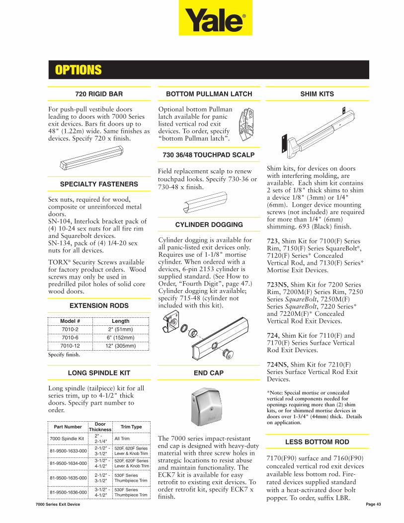
OPTIONS
Page 437000 Series Exit Device
Shim kits, for devices on doorswith interfering molding, areavailable. Each shim kit contains2 sets of 1/8" thick shims to shima device 1/8" (3mm) or 1/4"(6mm). Longer device mountingscrews (not included) are requiredfor more than 1/4" (6mm)shimming. 693 (Black) finish.
723, Shim Kit for 7100(F) SeriesRim, 7150(F) Series SquareBolt®,7120(F) Series* ConcealedVertical Rod, and 7130(F) Series*Mortise Exit Devices.
723NS, Shim Kit for 7200 SeriesRim, 7200M(F) Series Rim, 7250Series SquareBolt, 7250M(F)Series SquareBolt, 7220 Series*and 7220M(F)* ConcealedVertical Rod Exit Devices.
724, Shim Kit for 7110(F) and7170(F) Series Surface VerticalRod Exit Devices.
724NS, Shim Kit for 7210(F)Series Surface Vertical Rod ExitDevices.
*Note: Special mortise or concealedvertical rod components needed foropenings requiring more than (2) shimkits, or for shimmed mortise devices indoors over 1-3/4" (44mm) thick. Detailson application.
720 RIGID BAR
For push-pull vestibule doorsleading to doors with 7000 Seriesexit devices. Bars fit doors up to48" (1.22m) wide. Same finishes asdevices. Specify 720 x finish.
SPECIALTY FASTENERS
Sex nuts, required for wood,composite or unreinforced metaldoors.SN-104, Interlock bracket pack of(4) 10-24 sex nuts for all fire rimand Squarebolt devices. SN-134, pack of (4) 1/4-20 sexnuts for all devices.
TORX® Security Screws availablefor factory product orders. Woodscrews may only be used inpredrilled pilot holes of solid corewood doors.
730 36/48 TOUCHPAD SCALP
Field replacement scalp to renewtouchpad looks. Specify 730-36 or730-48 x finish.
CYLINDER DOGGING
Cylinder dogging is available forall panic-listed exit devices only.Requires use of 1-1/8" mortisecylinder. When ordered with adevices, 6-pin 2153 cylinder issupplied standard. (See How toOrder, “Fourth Digit”, page 47.)Cylinder dogging kit available;specify 715-48 (cylinder notincluded with this kit).
SHIM KITSBOTTOM PULLMAN LATCH
Optional bottom Pullmanlatch available for paniclisted vertical rod exitdevices. To order, specify“bottom Pullman latch”.
EXTENSION RODS
LONG SPINDLE KIT
Long spindle (tailpiece) kit for allseries trim, up to 4-1/2" thickdoors. Specify part number toorder.
END CAP
The 7000 series impact-resistantend cap is designed with heavy-dutymaterial with three screw holes instrategic locations to resist abuseand maintain functionality. TheECK7 kit is available for easyretrofit to existing exit devices. Toorder retrofit kit, specify ECK7 xfinish.
LESS BOTTOM ROD
7170(F90) surface and 7160(F90)concealed vertical rod exit devicesavailable less bottom rod. Fire-rated devices supplied standardwith a heat-activated door boltpopper. To order, suffix LBR.
Model # Length
7010-2 2" (51mm)
7010-6 6" (152mm)
7010-12 12" (305mm)
Specify finish.
Part NumberDoor
ThicknessTrim Type
7000 Spindle Kit2" - 2-1/4"
All Trim
81-9500-1633-0002-1/2" - 3-1/2"
520F, 620F SeriesLever & Knob Trim
81-9500-1634-0003-1/2" - 4-1/2"
520F, 620F SeriesLever & Knob Trim
81-9500-1635-0002-1/2" - 3-1/2"
530F SeriesThumbpiece Trim
81-9500-1636-0003-1/2" - 4-1/2"
530F SeriesThumbpiece Trim

Rim
Cyl
ind
er
NarrowEscutcheon Trim500F/510F SeriesRim cylinders withspecial # 599cylinder rings. NOTAVAILABLE withU5109 cylinder.
Application: Cylinder(s) Description Cylinder Ring Mounting Screws7200, 7200M,7200MF Rim7250, 7250M, 7250MFSquareBolt®
7210, 7210M,7210MF SVR7220, 7220M,7220MF CVR
1109 / 5109 6-pin Standard / Security 599-.419 60-7000-1235-048
1109 / 5109 7-pin Standard / Security 599-.419 60-7000-1235-048
1193 / 5193 6-pin I.C. / Sec. I.C. 599-.544 10-1193-1018-048
1193 / 5193 7-pin I.C. / Sec. I.C. 599-.544 10-1193-1018-048
1709 6-pin CMK Cylinder 599-.544 34-2311-8738-048
1709 7-pin CMK Cylinder 599-.700 34-2311-8738-048
StandardEscutcheon Trim520F/530FSeriesRim Cylinders
7100(F),7100(F)-2 Rim7150(F),7150(F)-2SquareBolt®
7110(F), 7170(F)SVR7120(F) CVR
1109 / 5109 6-pin Standard / Security 1765-.250 60-7000-1235-048
U5109 6-pin High Security ----- 60-7000-1235-048
1109 / 5109 7-pin Standard / Security 1765-.250 60-7000-1235-048
U5109 7-pin High Security 1766 60-7000-1235-048
1709 6-pin CMK Cylinder 1765-.656 34-2311-8738-048
1709 7-pin CMK Cylinder 1765-.656 34-2311-8738-048
1193 / 5193 6-pin Std. / Sec. I.C. 1765-.469 10-1193-1018-048
1193 / 5193 7-pin Std. / Sec. I.C. 1765-.656 10-1191-1018-048
Heavy-DutyEscutcheon Trim620F and 600Series ElectricTrimRim Cylinders
7100(F),7100(F)-2 Rim7150(F) 7150(F)-2SquareBolt®
7110(F), 7170(F)SVR7120(F), 7160(F)CVR
1109 / 5109 6-pin Standard / Security ----- 60-7000-1235-048
U5109 6-pin High Security ----- 60-7000-1235-048
1109 / 5109 7-pin Standard / Security ----- 60-7000-1235-048
U5109 7-pin High Security ----- 60-7000-1235-048
1709 6-pin CMK Cylinder 1765-.250 34-2311-8738-048
1709 7-pin CMK Cylinder 1765-.250 34-2311-8738-048
1193 / 5193 6-pin Std. / Sec. I.C. 1765-.250 10-1193-1018-048
1193 / 5193 7-pin Std. / Sec. I.C. 1765-.344 10-1193-1018-048
CYLINDERS
Page 44 7000 Series Exit Device
Note: Mounting screw part numbers shown are the screws to mount the cylinder.Note: Same cylinder used for inside and outside on double cylinder exit device..
Mo
rtis
e C
ylin
der
Application: Cylinder(s) Description Cylinder Ring
Mortise ExitDevices StandardEscutcheon trim550F/560F Series
7130(F), 7130(F)-2Mortise
2153/5153, 6 or 7-pin, 1-1/4" (29mm) Standard / Security 1765 - .062
2196 / 5196 6-pin Std. I.C. / Sec. I.C. 1765 - .344
2197 / 5197 7-pin Std. I.C. / Sec. I.C. 1765 - .531
U5153, 6 or 7-pin, 1-1/4" (32mm) High Security ----
Mortise Exit DevicesHeavy-Duty Escutcheon Trim650F Series
7130(F), 7130(F)-2Mortise
2153 / 5153, 6 or 7-pin, 1-1/2" (38mm)
Standard / Security ----
2196 / 5196 6-pin Std. I.C. / Sec. I.C. ----
2197 / 5197 7-pin Std. I.C. / Sec. I.C. 1765 - .062
Keyed Removable MullionsKRM100/100F
7100(F), 7150(F),7200, 7250,7200M(F), 7250(F)
2153/5153*, 6 or 7-pin, 1-1/8" (29mm) Standard / Security -----
2196 / 5196 6-pin Std. I.C. / Sec. I.C. 1765-.250
2197 / 5197 7-pin Std. I.C. / Sec. I.C. 1765-.250
Cylinder Dogging
SecureX® & Alarm Kit
Panic-rateddevices
All exit devices
2153 , 6-pin, 1-1/8" (29mm) Standard ----
2153, 7-pin 1-1/4" (32mm) Optional 7-pin 1765 - .156
2196, 6-pin 1-1/2" (38mm) Std. I.C. 6-pin 1765 - .406
2197, 7-pin 1-11/16" (42mm) Std. I.C. 7-pin 1765 - .594
As with exitdevice trim youmust order acylinder to gowith a keyedremovablemullion. TheYale keyedremovablemullion accepts astandard 6-pin2153 mortisecylinder withcam # 2160.Other cylindersare optional.
*U5153 6 and 7-pin cylinderscannot be usedwith a keyedremovablemullion.
Knob or Leverset Trim540F Series Trim Keyed trim uses Yale®
cylindrical lock cylinders.
Application: Cylinder(s) Description
7100(F) Rim7150(F) SquareBolt7110(F), 7170(F) SVR7120(F) CVR
1801 6-pin Knob Cyl. (Std.)1802 6-pin Lever Cyl. (Std.)
1802A 7-pin Lever Cylinder1210 6-pin I.C. Lever Cylinder1220 7-pin I.C. Lever Cylinder5802 6-pin Security Lever Cyl.
5802A 7-pin Security Lever Cyl.5210 6-pin I.C. Security Cyl.5220 7-pin I.C. Security Cyl.107S Adaptor kit for Schlage® Cyl.
“B” Trim PrefixTrim with lever for Best®, Arrow® or Falcon® IC
cylinder (specify 6 or 7-pin)“R” Trim Prefix* Trim with lever for Corbin Russwin IC cylinder
*AU & PB levers only.
Refer to separate catalog section for availability.
Note: Inside cylinder for double cylinder exit device is 2-3/4” (70mm) length with 1765-.250 ring

FACTS AND FIGURES
Page 457000 Series Exit Device
7100 and 7100F Series(all variables)
7200 and 7200M Series(all variables)
600 Series
10-1/4"
3"
520/550 Series
9-1/2"
2-1/2"
530/550 Series
15-1/4"
2-1/2"
6-7/16"
500F Series 510F Series
9-1/2"
1-5/8"
15-1/4"
2-1/2"
6-7/16"
2-1/2"
1/4"
1-5/8"
Arcadia
Projection: 2-5/16" (59mm)
Augusta
Projection: 3-1/16" (78mm) Projection: 2-7/8" (73mm)
Carmel
Projection: 2-3/8" (60mm)
Jefferson
Projection: 2-3/16" (71mm)
Projection: 2-7/8" (73mm) Projection: 2-3/4" (70mm)
Pinehurst Virginia
Projection: 2-11/16" (68mm)
Brandywine
Projection: 3-1/8" (79mm)
Copenhagen
Projection: 2-1/2" (64mm)
LFVI
JN
PN
CR
CO
AU
BR
MOAR Monroe
Projection: 2-3/4" (70mm)
Pacific Beach
Litchfield
Projection: 2-15/16" (75mm)
CA* Carolina
PB
*CA knob available for 540F Series trim only.
Series “A” “B”
7100-36 32-7/8"(835mm)
18"(457mm)7100F-36
7100-48 44-7/8"(1130mm)
24"(610mm)7100F-48
Series “A” “B”
7200-3634-5/8"
(880mm)18"
(457mm)7200M-36
7200MF-3632-7/8"
(835mm)18"
(457mm)
7200-4846-5/8"
(1184mm)24"
(610mm)7200M-48
7200MF-4844-7/8"
(1130mm)24"
(610mm)
LEVER AND KNOB DESIGNS
TRIM DIMENSIONS
Projection:13/16" (20mm)
Projection:1/4" (6mm)
Projection:2-1/8" (54mm)
Projection:1/4" (6mm)
Projection:2-1/8" (54mm)

SAMPLE SPECIFICATIONS
Page 46 7000 Series Exit Device
SPECIFICATION
Exit devices shall be 7000 Series Pushpad Exit Devices asmanufactured by Yale Commercial Locks and Hardware.
The exit device chassis shall be cold forged steel,electroplated for corrosion resistance, and shall bearchitecturally finished brass, bronze or stainless steel. Thepushpad mechanism shall be constructed of extrudedaluminum and shall be scalped with architecturally finishedbrass, bronze or stainless steel. The maximum projectionshall be 3-1/4" when the pushpad is active and 2-3/4" whenthe pushpad is dogged down. Nylon bearings and stainlesssteel springs shall be used for long life and durability; onlytorsion springs are acceptable. Rear and active case coversshall be wrought brass or bronze and shall be plated tomatch the exit bar. Plastic or painted covers are notacceptable. Latchbolts shall be steel and shall incorporate adeadlocking latch for increased security. Devices withoutdeadlocking latches are not acceptable. Mounting screwsshall be concealed to deter tampering. Devices shall beclosed on all sides with no pinch points. Exit devices shallbe easily field sized to accommodate various door widths.
Panic-listed exit devices shall have single point, one quarterturn hex key dogging standard. Optional cylinder doggingshall be available on panic listed devices. Devices with hexkey dogging shall be easily field converted to cylinderdogging. Panic listed devices shall be available less dogging.
Trims shall be throughbolted with concealed fasteners.Escutcheon and pull-type trims shall be constructed of brassor bronze. All lever trims shall use cast or forged levers. Onrim, SquareBolt® and vertical rod trims with cylinders, themechanism that locks and unlocks the trim shall be housedin the trim and not in the active case of the exit device.Lever trims (except mortise) shall be Free-Wheeling withclutch mechanism allowing lever to rotate 60° when lockedto prevent vandalism. Lever trims shall match those onYale® mortise and cylindrical locksets.
Exit devices and trims shall be furnished in BHMAstandard architectural finishes.
Exit devices shall be listed by Underwriters Laboratories(UL) for safety as panic hardware. Fire-rated devices shallbe listed for A label and lesser class doors.
Certification:Federal Specification FF-H-1820ANSI A156.3, Grade 1
Devices, trims and cylinders shall be from onemanufacturer.
Devices and 600 Series trim shall carry a five-year limitedwarranty.
500 Series trim shall carry a one-year limited warranty.
Electronic components shall carry a one-year limitedwarranty.
SECUREX® SPECIFICATION
Delayed egress exit devices shall be 7100/7200 Series (rim,SquareBolt®, mortise or concealed vertical rod) with the“D” suffix, manufactured by Yale Commercial Locks andHardware.
The SecureX device secures the door in the locked mode.Depressing the pushpad for less than three seconds willsound the device siren without initiating the alarm.Depressing the pushpad longer than three seconds willinitiate an irreversible local audible beeping tone and allowthe device to release for egress after 15 seconds. The alarmwill continue until reset by the mechanical key switchlocated on the device. (When acceptable by local codeagency, the delay period may be increased to 30 seconds, orother approved amount of time. Consult factory.)
Devices shall be 24 volts DC.
The exit device chassis shall be cold forged steel,electroplated for corrosion resistance, and shall bearchitecturally finished brass, bronze or stainless steel. Thepushpad mechanism shall be constructed of extrudedaluminum and shall be scalped with architecturally finishedbrass, bronze or stainless steel. The maximum projectionshall be 3-1/4" when the pushpad is active and 2-3/4" whenthe pushpad is depressed. Nylon bearings and steel springsshall be used for long life and durability. Active case andalarm end cover shall be wrought brass, bronze or stainlesssteel and shall be plated to match the exit bar. Painted orplastic covers or end caps are not acceptable. Latchboltsshall be steel and shall incorporate a deadlocking latch forincreased security. Devices without deadlocking latches arenot acceptable. Mounting screws shall be concealed to detertampering. Devices shall be closed on all sides with nopinch points. Device active cover and end cap attachingscrews shall be security TORX®. When required, doorposition switches used on rim or SquareBolt devices shallbe incorporated into the latch assembly of the device toallow added security.
Trims shall be through-bolted with concealed fasteners.Escutcheon and pull-type trims shall be constructed ofbrass, bronze or stainless steel. All lever trims shall use castor forged levers. On rim, SquareBolt and vertical rod trimswith cylinders, the mechanism that locks and unlocks thetrim shall be housed in the trim and not in the active headof the exit device. Lever trims shall match those on Yalemortise and cylindrical locksets. Lever trims (exceptmortise) must have a clutch or Free-Wheeling springassembly when in the locked mode to deter vandalism ordamage to trim. Rigid lever trims are not acceptable.
Exit devices, trims and cylinders must be from onemanufacturer.

HOW TO ORDER
Page 477000 Series Exit Device
From this outline select the Model Number for the Yale® 7000 Exit Device Series you require.
Notes:1. Required for electrical feature, Suffix “-SAFE” or “-SECURE”.2. LBR available on 7160(F90) and 7170(F90) devices only.3. For double cylinder devices, suffix “-2” after fourth digit
It is recommended that exit devices and trim for the same opening be ordered together. Standard product and warehouseinventories are for 1-3/4" (44mm) reinforced metal doors. Accessories detached from the device and trim should bespecified separately. Materials by others are required to be fit for the purpose as detailed in this catalog and the productinstallation literature.
Exit Device Only7150D-36 x 626 x RHR x SNB
Exit Device with Trim and Cylinder7170F90-9-48 x AU626F x 605 x LHR x 1109 GA 0-bit
Trim OnlyMO656F x 630 x RHR x LC
Double Cylinder Exit Device with Trim7150F-2-36 x AU626F x 630
ORDERING EXAMPLES
7 X X X Mechanical/Electrical Size Design Trim Finish Other Info.
SecondDigit:“1” -Standarddevice, 4-1/2"(114mm) orwider doorstile.
“2” -Narrowstile door or narrow escutcheontrim (500F,510F Series)
Third Digit:“0” -Rim Device,Pullman Latch
"1" -SVRDevice up to 8'
“2” -CVRDevice, MetalDoors up to 8'
“3” -MortiseDevice
“5” SquareBolt®,Rim Security
“6” -CVRDevice over 8'
“7” - SVRDevice over 8'
Fourth Digit:“0” - Standard
“5” - CylinderDogging (Notwith suffix “F”)
Mechanical Feature“F” - Fire Exit Device“M” - Narrow escutcheon
Trim in 4-1/2" (114mm) or wider door stile
“LBR”- Less Bottom Rod (Note 2)
“K5” - Mortise Device, EO,Entry by Key, or Key Override.
“K8” - Mortise Device, Entry by Knob
“L5” - Mortise Device, Rigid Lever or Key Override (Note 1)
“L8” - Mortise Device, Entry by Lever
“T5” - Mortise Device withThumbpiece Trim
“T8” - Mortise Device, active Thumbpiece Trim
“2” - Double Cylinder Device (Note 3)
Electrical Feature“-A” - Alarm Kit“-B” - Bar Monitor or
Signaling“-D” - Delayed Egress“-ES” - Electric Strike
Compatible“-G” - Electric Dogging“-O” - Outside Trim
Monitor or Signaling
“-P” - Latch Pullback “-S” - Bolt Status Monitor
or Signaling“-Safe” - Mortise Device
Trim Control“-Secure” - Mortise Device
Trim Control
Size:DOW =DoorOpeningWidth)
“36” - 30" to 36"DOW
“48” - 36" to 48"DOW
“24” - 24" to 30"DOW
DoorHeight:-8 = 8'(2.44m)
-9 = 9'(2.74m)
-10 = 10'(3.05m)
TrimDesign(Lever orknob only)
TrimModelNumber
SeePage 3
OtherInformation:Door Hand- RHR or LHR
DoorThickness- Over 1-3/4"(45mm)
FastenerOptions- TORX®
SecurityScrews SNB (wood, composite, orunreinforced metal doors)
SpecialtyCylinders &Components

For the latest information on YaleCommercial Lock and Hardware products,visit our website at www.yalecommercial.com.
Click on the “Literature” button to find:
■ Catalogs■ Parts manuals■ Templates■ Specifications■ Installation instructions
Yale® customers can click on the ebusinesssymbol on the website to register for an ebusiness account to:
■ Check the status of orders■ Check availability of QuickShip items■ Track your order and confirm delivery■ Receive email notification of template
changesAnd More...
42139-MA-15.0-07/04R
Yale Commercial Locks and Hardware
Address: 1902 Airport Road, Monroe, NC 28110 USA
Tel: 1-800-438-1951 • Fax: 1-800-338-0965 • www.yalecommercial.com
Yale-Corbin Canada Ltd.
Address: 6940 Edwards Boulevard, Mississauga, Ontario, Canada L5T 2W2
Tel: 1-800-461-3007 • Fax: 1-800-461-8989 • www.yalecorbin.on.ca
Yale®, Yale Security Inc.®, SquareBolt®, and SecureX® are registered trademarks of Yale Security Inc. Free-Wheeling and Design™ is a trademark of Yale Security Inc. Folger Adam® is a registered trademark of Folger Adam Security Inc. Other products brand names may be trademarks or registered trademarks of their respective owners and are mentioned forreference purposes only. Copyright© 2002, 2004 Yale Security Inc. All rights reserved. These materials are protected under US copyright laws. All contents current at time of publication.Yale Security Inc. reserves the right to change availability of any item in this bulletin, its design, construction, and/or its materials.
The ASSA ABLOY Group is the world’s leading manufacturer and supplier of locking solutions, dedicated to satisfying end-user needs forsecurity, safety and convenience.
online literatureand templates
www.yalecommercial.com