architectural cladding systemscms.esi.info/media/documents/81847_1477477874317.pdf · distribution....
TRANSCRIPT

ARCHITECTURAL CLADDING SYSTEMS
July 2016

Image by Paul Zanre Photography.

Introduction 2
Principles of rainscreen cladding 4
Design services 6
Integrated production process 8
Features and applications 10
Systems 12
BML60 14
BML100 15
BML120 16
BML200 17
BML400 18
BML Norbo 19
BML Opus 20
BML Spandrel 21
Rainspan 22
Material supply 24
Colours and finishes 26
Fire safety compliance 28
Thermal performance 30
Refurbishment 32
BML smart fixing systems 34
System components 40
Case studies 42
Projects gallery 50
CONTENTS
1

2

3
Booth Muirie has gained national recognition
for the provision of a comprehensive range
of specialist architectural cladding services,
including design, manufacturing and
distribution.
Cost effective, time sensitive solutions can be
identified, without compromising service quality,
through the combined knowledge and expertise
within the company.
Creating innovative architecturalsolutions for over 40 years
With a strong awareness of market demands
and a progressive, forward thinking approach to
ever-evolving design trends, Booth Muirie has
positioned itself as a highly respected specialist
company within the construction industry.
Booth Muirie uses a range of metal composite
materials (MCM), predominantly aluminium
composite materials (ACM), to manufacture
rainscreen cladding systems. MCMs consist of
two thin skins of aluminium or other metals such
as copper, zinc and stainless steel, continuously
bonded under tension to either side of a
thermoplastic or mineral core.
Booth Muirie rainscreen constructions are
referred to as BML Systems, with the different
constructions recognised by a standard prefix of
BML (Booth Muirie LINEAR), followed by a specific
reference, which identifies the system construction,
such as BML200.
INTRODUCTION

Rainscreen is a cladding applied either during
primary construction or as an over-cladding to
an existing structure. Rainscreen cladding
consists of an outer weather-resistant
decorative skin fixed to an underlying structure
by means of a supporting grid, which maintains
a ventilated and drained cavity between the
façade and the structure.
Rainscreen façades are not normally sealed and a
ventilation cavity of at least 25mm is allowed
immediately behind the cladding panel. Insulation
can be positioned within the cavity whilst openings
at the top and bottom of clad areas allow for
evaporation of moisture vapour and
ventilation/drainage.
A ventilated rainscreen incorporating insulation
will allow the building fabric to breathe without the
risk of interstitial condensation or structural decay.
External wall insulation used in this way is superior
in performance as it eliminates the condensation
risks associated with internal or cavity wall
insulation. This is particularly important for
refurbishment schemes. In new construction the
use of back ventilated rainscreen cladding
provides the designer with the opportunity to use
economical single skin load bearing block work
for infill walls.
The need for complicated damp proof membrane
detailing is eliminated and there will be less risk of
cold bridging. The air gap provides ventilation
and depending on the design of the rainscreen, in
conjunction with ventilated panel joints, it may also
assist in providing pressure equalisation across the
outer skin.
4
PRINCIPLES OF RAINSCREEN CLADDING
Ventilation

5
Fully pressurised and compartmentalised (zoned)
systems control airflow locally and are usually used
on high performance, multi-storey developments.
Where lower performance is required, for example
in low rise structures, then a similar cassette panel
system, although not fully pressure equalised,
performs well.
The pressure equalisation concept is realised when
outside air pressure is transferred to an air space
behind the exterior cladding. The air gap
compartments must be small enough, the air
barrier system must be airtight enough and the
area of the venting through the rainscreen must be
large enough to allow sufficient air to move in and
1. Panel to soffit transition. 2. Curtain wall interface. 3. Section through cill.
4. Section through vertical joint. 5. Section through window head. 6. Section through corner panel.
out of the compartments under the applied air
pressure. The strategy relies on the control of
airflow within and through the wall assembly.
In theory, pressure equalisation means a zero
air pressure differential at all times across the
rainscreen, resulting in a complete elimination
of the driving force for pressure-induced water
penetration.

6

7
The design and manufacture of engineered
rainscreen façades, featuring ACM or MCM,
is at the heart of what Booth Muirie does.
The company has built a reputation for providing
rainscreen cladding solutions for a
comprehensive range of projects and has an
exceptional architectural portfolio. This is due,
in no small part, to the design capabilities of
the business.
The Design Team uses modern computer aided
design (CAD) software to help deliver creative
architectural solutions. Technically innovative
cladding systems are delivered through the
interpretation of architectural drawings and the
creation of in-house details. This design ability
perfectly complements Booth Muirie’s capabilities
as a leading fabricator, by ensuring pragmatic
solutions are developed, which can be efficiently
manufactured.
Design team
A Project Designer is appointed to work closely
with customers to ensure effective communication
and project management. The team of designers
employed by Booth Muirie has worked on a
comprehensive range of architectural projects,
offering customers a variety of drawing services
and full compatibility through the use of the latest
CAD software.
The standard Booth Muirie products cover many
requirements but there may be a need to provide
bespoke details or features. Booth Muirie takes
pride in the ability to offer flexibility in design and
manufacture, working in-house or in partnership
with specialist consultants to achieve a solution
that best fits the design aspirations.
Technical support
Full technical support is available on all aspects of
service and products. Materials are fully compliant
and tested to the relevant industry standards, whilst
manufacturing processes are certified ISO 9001.
Facade panels
Bespoke façade panels, using established
installation systems, can be supplied in a wide
range of MCMs, particularly ACM, which opens up
a host of possibilities in terms of colour and finish.
Panels can be supplied in different shapes and
sizes to suit almost any façade design; from the
simplest linear form to the most avant-garde design.
As well as rainscreen panels Booth Muirie can
produce spandrel panels that can be tailored to
the colour scheme of the building, creating a
match or contrast with the glazed area and offering
the opportunity to enhance the visual impact
of the curtain wall or glazing.
Feature detailing
Combined with façade panels, feature details offer
a solution to complete all roof and wall interfaces.
These can include bullnoses, transitions and
corners, highly flexible flashings, interior walls and
ceilings, column casings and soffit panels. Window,
door and curtain wall interfaces are also available.
Booth Muirie systems can help achieve grand
designs or add that special finishing touch.
The accuracy of the CAD modelling team ensures
that every panel fits as intended. For details of the
manufacturing constraints relating to any particular
material please contact the office.
DESIGN SERVICES

8
Booth Muirie has been manufacturing
rainscreen systems in the UK and Ireland since
1978. Using original concepts, the company
has evolved and innovated to become a key
presence in the technically challenging
rainscreen cladding market. Since becoming a
Euroclad company, Booth Muirie has continued
to grow, through a commitment to technical
excellence and robust supply.
Concept to reality
It all begins with the Booth Muirie technical team.
Years of system and detailing expertise means that
design expectations can be defined and achieved,
whilst ensuring Building Regulation compliance.
Optimum manufacturing and installation options
are advised to achieve the fastest, most cost-
effective solutions.
Once a Bulk Order is placed the production
process commences. Material is allocated from
stock or ordered to specification, whilst system
drawings are created by the Technical Drawings
team. Following contractual sign off, delivery
dates are agreed.
Bespoke software
The next stage of the process is an advanced
software solution that has been exclusively
designed and developed for Booth Muirie.
Through the integration of existing and bespoke
software, drawing files link with the panel
production details, which are then imported into
the production machinery. This advanced process
optimises sheet utilisation and minimises machine
time, keeping material and processing costs to a
minimum by reducing waste and improving
efficiency.
INTEGRATED PRODUCTION PROCESS

9
The software also creates works orders and allows
a view of where each panel for each job is within a
production run. Each panel has a unique
identification number that is used throughout the
production and delivery process and is shown on
the panel as a QR code. The QR code is a clever
bar code solution that is easily read by a range of
devices including iPads and smartphones. As well
as containing the panel ID number the QR code
can also be created with useful data for site
operatives.
Once material is allocated to the works order and
scheduled, files are downloaded to the router and
production can begin.
Material routing
Cutting, drilling and routing ACM is performed
by large, flat-bed, multi-tool machines, that are
operated and monitored by experienced staff as
they follow a pre-programmed set of actions,
based on the previous stages of the process.
The routing of ACM means that sheet and panel
sizes can be processed in lengths of more than
seven metres, with the 'v' groove routed into the
panel providing an easily folded edge. This avoids
any requirement for machine folding and any
associated process restrictions. As such, the panels
are finished by hand, after being uniquely labelled
and then scanned.
Assembly
Panels are scanned into the assembly process and
finished by hand using the most suitable methods
for the kind of panel being assembled.
Once complete, panels are stored in a dedicated
area ready for packaging, away from the hustle and
bustle of production and assembly.
Packing and loading
Panels are packaged on pallets, with each pallet
also featuring a unique QR Code that can be
traced to the relevant works order. Operators scan
the panels while packing them, which shows the
progress of the work order and highlights any
items left to pack, as well as their current position
in the production process. When a pallet of panels
is completed, specific paperwork and labels are
automatically created and the loaded pallet is
made available for delivery.
The QR code sticker is removed from the pallets as
they are loaded onto the delivery vehicle and
placed onto the loading document. They are then
scanned to record the movement of the pallet from
packing to delivery. This also prompts the creation
of delivery notes and provides information to
SAGE invoicing systems.
Traceability
The pallet QR code can be scanned by any mobile
device with a QR Code Scanner App, which can
record the information for easy panel tracking. This
has been embraced onsite as a key benefit of
Booth Muirie’s product supply, locating the correct
panels infinitely faster, easier and more accurately
than previously possible.
The entire process and its stages are fully audited,
providing complete traceability throughout
production, packing and delivery. Armed with this
level of detail, processes are continually improved
where appropriate and this has resulted in
significant enhancements to production planning,
delivery scheduling and stock control. The benefit
of this to Booth Muirie customers is increased
productivity, quality and reliability.

The wide range of materials and panel types
available to Booth Muirie’s BML Systems allows
the designer the freedom and confidence to
realise inspiring building designs.
The nature of the composite materials used in
BML Systems provides rigidity, flatness and colour
uniformity. BML Systems can be applied to new or
refurbished buildings and they can be used to
great effect for a wide variety of applications; from
the entire facade of monolithic high-rise buildings
to feature details that are distinctive and charming.
Booth Muirie designs and manufactures a wide
range of products, which offer a variety of solutions
for diverse applications, including:
1. BML Systems for rainscreen cladding
2. Spandrel panels
3. Soffit panels
4. Column casings
5. Bullnoses and roof perimeter details
6. Interior partitions and ceilings.
Booth Muirie can help achieve grand designs or
add that special finishing touch; providing a wide
choice of products, supported by precise design,
engineering and manufacturing.
FEATURES AND APPLICATIONS
10
1
2

11
3
4
5
6

12
SYSTEMS
Booth Muirie systems provide a wide range ofchoice in terms of materials, colours, finishes,panel types and panel orientations. They arealso suitable for installation as part of a varietyof substructures, meaning that the systems areversatile, relevant and practical for a host ofdesign specifications.

Timber. Rainspan.
13
Substructures
BML Systems are suitable for use with
steel, concrete, brick, block or timber
substructures. The Rainspan system,
supplied in partnership with Eurobond,
combines the performance of a
structural insulated panel with the
aesthetics of Booth Muirie rainscreen
construction.
Panel options
A range of panel types is available
incorporating standardised systems
as well as bespoke solutions. Curved
and non-standard panels can be
produced, offering design flexibility.
Panels can be laid to suit specific
design requirements, in horizontal or
vertical format, as stepped panels or
even as irregular diagonals.
Metsec.
Materials
BML Systems are available in a wide
range of MCMs including zinc,
copper, aluminium, stainless steel
and titanium, as well as the ever-
popular ACM. More information on
materials, colours and finishes is
contained on pages 24 to 27.
Brick.
Concrete.

14
Substructure 1. Two layers of 2.5mm plasterboard
2. Vertical studs at maximum 1m centres
3. Mineral fibre insulation
4. 12mm cement particle board
5. Waterproof sheet
6. Adjustable wall bracket
Rainscreen insulation 7. Rigid board or dual-density slab(may or may not be present)
BML60 8. BML Smart Fixing System
9. BML60 panel
9
5
6
7
8
SYSTEMS – BML60
Horizontal section. Vertical section.
A2DF
A2DF
1 2 3 4
An open joint rainscreen system with
variable joint widths, which can be
used for landscape panels as part of
a vertical wall cladding system.

15
Substructure 1. Two layers of 2.5mm plasterboard
2. Vertical studs at maximum 1m centres
3. Mineral fibre insulation
4. 12mm cement particle board
5. Waterproof sheet
6. Adjustable wall bracket
Rainscreen insulation 7. Rigid board or dual-density slab(may or may not be present)
BML100 8. BML Smart Fixing System
9. BML100 panel
A hook-on, open joint rainscreen
system with variable joint widths
which is best suited for portrait
panels as part of a vertical wall
cladding system, as well as fascia
applications.
Available with a hook-and-pin or a
hidden plate variation of hook-on
BML Smart Fixing Systems.
SYSTEMS – BML100
Horizontal section. Vertical section.
A2DF
A2DF
9
5
6
7
8
1 2 3 4
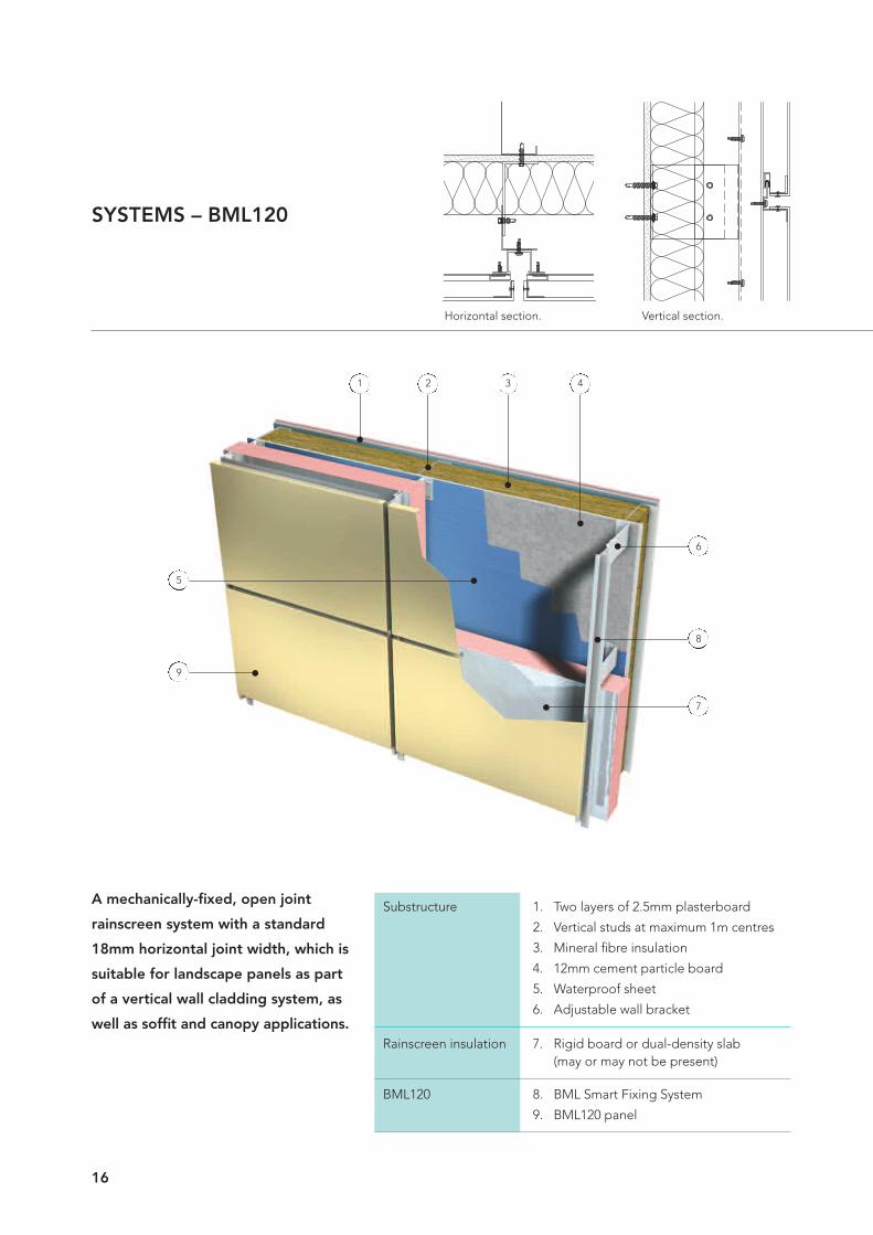
A mechanically-fixed, open joint
rainscreen system with a standard
18mm horizontal joint width, which is
suitable for landscape panels as part
of a vertical wall cladding system, as
well as soffit and canopy applications.
SYSTEMS – BML120
16
Horizontal section. Vertical section.
9
5
6
7
8
1 2 3 4
Substructure 1. Two layers of 2.5mm plasterboard
2. Vertical studs at maximum 1m centres
3. Mineral fibre insulation
4. 12mm cement particle board
5. Waterproof sheet
6. Adjustable wall bracket
Rainscreen insulation 7. Rigid board or dual-density slab(may or may not be present)
BML120 8. BML Smart Fixing System
9. BML120 panel

17
SYSTEMS – BML200
A mechanically-fixed system, with
a joint width of 20mm, which is
suitable for all panel formats as part
of a vertical wall cladding system,
as well as soffit, canopy and column
casing applications.
Horizontal section. Vertical section.
A2DF
A2DF
9
5
6
7
8
1 2 3 4
Substructure 1. Two layers of 2.5mm plasterboard
2. Vertical studs at maximum 1m centres
3. Mineral fibre insulation
4. 12mm cement particle board
5. Waterproof sheet
6. Adjustable wall bracket
Rainscreen insulation 7. Rigid board or dual-density slab(may or may not be present)
BML200 8. BML Smart Fixing System
9. BML200 panel

A face fixed rainscreen system which
is suitable for all panel formats as
part of a vertical wall cladding
system, as well as soffit and column
applications.
SYSTEMS – BML400
18
Horizontal section. Vertical section.
A2DF
A2DF
9
5
6
7
8
1 2 3 4
Substructure 1. Two layers of 2.5mm plasterboard
2. Vertical studs at maximum 1m centres
3. Mineral fibre insulation
4. 12mm cement particle board
5. Waterproof sheet
6. Adjustable wall bracket
Rainscreen insulation 7. Rigid board or dual-density slab (may or may not be present)
BML400 8. BML Smart Fixing System
9. BML400 panel

19
The BML NORBO interlocking
cladding system is made up of
extruded aluminium sections,
providing a durable facade with an
attractive appearance, in a choice
of colours and finishes.
SYSTEMS – BML NORBO
Vertical section.
A2DF
A2DF
Horizontal section.
1 2 3 6 4 4 4 663 32 211 1
18
100
21
29
200
60
R20
100
9
Norboprofile 554
Norboprofile 220sinusoidal
Norboprofile 605
1110 7 77 89 8 8
Substructure 1. Two layers of 2.5mm plasterboard2. Vertical studs at maximum 1m centres3. Mineral fibre insulation4. 12mm cement particle board5. Waterproof sheet6. Adjustable wall bracket
Rainscreen insulation 7. Rigid board or dual-density slab(may or may not be present)
BML NORBO 8. BML Smart Fixing System9. BML NORBO 220 profile10. BML NORBO 554 profile11. BML NORBO 605 profile

20
Opus is a plank cladding productthat can be installed as a BMLSystem.
SYSTEMS – BML OPUS
Horizontal section. Vertical section.
A2DF
A2DF
UNDULATIONS IN PANEL: Due to the materials and processes used to manufacture Opus panels it is normal to see variations and undulations in its surface after installation. This characteristic is inherent in Opus panels and is part of the aesthetic appeal of the product. It is not considered a fault. It should be noted that darker colours and smoothcoatings are more prone to visible variations in the flatness of the pan. Horizontal orientation of panels, low incident light, along with the alignment and tolerances of thesupporting structure can also contribute to making the effect more noticeable. Maximum module width 300mm.
9
5
6
7
8
1 2 3 4
Substructure 1. Two layers of 2.5mm plasterboard
2. Vertical studs at maximum 1m centres
3. Mineral fibre insulation
4. 12mm cement particle board
5. Waterproof sheet
6. Adjustable wall bracket
Rainscreen insulation 7. Rigid board or dual-density slab(may or may not be present)
BML OPUS 8. BML Smart Fixing System
9. BML OPUS panel

21
Spandrel panels are used in place of glazing
units in curtain walling systems where it is
necessary to hide the edges of floor slabs,
ceiling details, insulation and other building
elements.
1. ACM panel
2. Aluminium tray casing
3. Insulation
4. Proprietary curtain walling section
SYSTEMS – BML SPANDREL
4
12
3

22
RAINSPAN®
Rainscreen support panel system
Rainspan® is a stone wool core composite panel
which acts as a long-spanning substrate to
rainscreen support systems, providing high levels
of fire protection and thermal performance.
Supplied by Eurobond Laminates Ltd, one of the
UK’s biggest manufacturers of non-combustible
composite panels, Rainspan® can be used as a
substrate for any standard or bespoke BML System.
Rainspan® is the perfect structural support for
rainscreen systems, combining ease and speed of
installation to create a weathertight building
envelope early on in the build programme.
An independent cost comparison was
commissioned in 2014, carried out by Faithful &
Gould, which concluded that Rainspan® combined
with rainscreen systems can be constructed with
cost savings of up to 40% versus traditional
blockwork and jumbo metal stud back walls.
The Eurobond Rainspan® panel is tested and
approved to the fire-related, insurance driven Loss
Prevention Standard LPS 1208 as well as countless
relevant construction standards, including
structural and weather integrity performance to
CWCT standards and fire resistance tests
conducted in accordance with BS EN 1364 Part 1,
to ensure ‘built-in passive fire protection’.
Eurobond Laminates Ltd provides environmentally
friendly design solutions. The Rainspan® panel
system has been independently tested for air
tightness, achieving outstanding air permeability
results of less than 1m³/hr/m², whilst featuring
excellent thermal insulation provided by the stone
wool core. This combined thermal performance
helps to reduce lifetime operational costs and
improve energy performance. Rainspan® is
manufactured from materials with high recycled
content and the panels are fully recyclable.
Rainspan® is a registered trademark of Eurobond Laminates Ltd.

23

24
MATERIAL SUPPLY
The materials used by Booth Muirie are MetalComposite Materials, known as MCMs. Theseare comprised of two metal skins that arebonded to a central core, encompassing a rangeof metals, such as copper, titanium and steel.The most popular MCM used in the constructionof rainscreen façades is Aluminium CompositeMaterial (ACM).
MCM is ideal for the construction of rainscreen
façades, providing the malleability that perfectly
suits it to panel formation using advanced cutting
and routing machines. This workable property
combines with rigidity and flatness for a clean,
unblemished façade surface. It also weighs much
less than equivalent gauge solid material, making
it easier to handle and subsequently easier to
manufacture and install.
MCM offers the designer greater flexibility,
features excellent flatness and rigidity, and is
lightweight; providing a universally suitable
material for rainscreen façade design, manufacture
and installation.
Booth Muirie is an independent fabricator and can
use any brand of ACM that is listed in a building's
specification. Three of the most popular
ACM/MCMs are ALPOLIC®, ALUCOBOND® and
larson®, which are all available from Booth Muirie.
The table below provides a general reference to
these three brands.
Visit the Materials section of the Booth Muirie
website to access more information and to
download material colour charts.
Brand ALPOLIC® ALUCOBOND® larson®
Manufacturer Mitsubishi Plastics 3A Composites Alucoil
ALUCOBOND® plusMaterial ALPOLIC®/fr ALPOLIC®/A2 ALUCOBOND® A2 ALUCOBOND® larson® (FR) larson® (PE)
ACM l l l l l l
MCM l l l l
Gauge 3mm l l l l l l
4mm l l l l l l
6mm l l l l
Core Mineral l l l l
Polyethylene l l
Finish Solid colours l l l l l l
Metallic colours l l l l l l
Special finishes l l l l l l
Anodised aluminium l l l l l l
Natural Copper l l l l
metals Brass l l
Zinc l l l l
Stainless steel l l l l
Titanium l l

25
Fire performance of ACM
The resistance to fire performance of ACM is
influenced by the combined performance of the
painted aluminium surface and the core material.
The type of core material used and the manner
in which it is fused to the aluminium skins is the
primary influencer in respect to the composite
material's resistance to fire.
There are generally three types of ACM available
with differing levels of resistance to fire.
These typically feature three types of core:
• Polyethylene (PE) is combustible;
• Fire Resisting (FR) contains a mixture of
combustible polyethylene and minerals that
limit the proliferation of flame and restrict the
development of smoke;
• A2 primarily consists of minerals that limit the
proliferation of flame and restrict the
development of smoke.
As an independent fabricator, Booth Muirie can
offer ACM with any of these three core types
however not all brands of ACM are available with
FR or A2 cores. For detailed information on the
resistance to fire performance associated with the
ACM brands commonly used by Booth Muirie visit
www.boothmuirie.co.uk.

COLOURS AND FINISHES
1. Solid colours
There are a wide range of standard colours
available to meet design requirements.
ACM is available for solid colours, which are
sufficiently varied to meet the majority of colour
specifications.
2. Metallic colours
Some of the most popular colours that are
specified for ACM rainscreens are metallic ones.
Colours such as silver metallic have been used on
seminal buildings for the last decade and their
popularity endures; combining stylish looks with
the peace of mind of a tried-and-tested colour.
3. Special finishes
There are a number of interesting special
finishes, including sparkling and prismatic
colours, as well as patterned finishes with the
appearance of timber, stone and metals such
as weathered copper.
4. Anodised ACM
Anodised aluminium features a strong coating,
which forms on the surface of aluminium as part
of the anodising process. The result is an extremely
hard substance. Special dyes and processes can
be used to colour anodised aluminium to achieve
distinctive colours, pseudo-metal finishes and
other unique effects.
5. Natural metals
Natural metals are MCMs that feature genuine
metals that behave in exactly the same way as
standard material but with the additional benefits
of a composite material. The natural metals
available are:
• Copper Composite Material (CCM)
• Stainless Steel Composite Material (SCM)
• Titanium Composite Material (TCM)
• Zinc Composite Material (ZCM)
• Brass Composite Material (BCM).
26

1. Southern General Hospital, Glasgow.
2. Milton Keynes Leisure Complex.
3. St. Giles Hotel.
4. WJEC.
5. Princess Hay.
5. Copper Egg.
27

28
FIRE SAFETY COMPLIANCE
Designing multi-layered walls that are compliant with Approved Document B2,featuring rainscreen panel systems formed from ACM.
Introduction
Rainscreen cladding systems, including those from
Booth Muirie, are increasingly popular in modern
construction, particularly on buildings with storey
heights of 18m or more above ground level. This
raises questions about building regulation
compliance for fire safety.
Where buildings are less than 18m in height, there
is no restriction on the use of combustible
materials, meaning that any option and
combination of materials is possible. If the
building has a storey of 18m or more above
ground level, the Building Control Alliance
recommends four options for showing compliance
with paragraph 12.7 of Approved Document B2.
These options are outlined below.
Option 1
The first and most straightforward way to design
a rainscreen system to be compliant with AD B2
is to use only non-combustible and/or limited
combustibility materials for all significant elements
of each and every layer of the wall.
This would therefore include: internal lining
boards; insulation within the back wall (if any,
except if the back wall is masonry cavity
construction, which is excluded); sheathing boards;
insulation within the rainscreen cavity (if present);
and rainscreen panels.
This restricts the choice of materials to those listed
‘Non-Combustible or Limited Combustibility’.
Limited combustibility (Euroclass A2, or better)
can be defined as materials which are classified as
non-combustible or fulfilling the criteria detailed in
AD B2 Tables A6 and A7 respectively. If in doubt a
copy of the products Declaration of Performance
(DOP) should be obtained, which will clearly
indicate the EN 13501-1/2 Reaction to Fire
Classification. Gaskets, sealants and similar non-
significant elements can be omitted from the
limited combustibility definition.
Option 2
If one or more of the layers is not defined as
‘Non-Combustible or Limited Combustibility’,
then a second route to compliance is possible.
This second option for compliance is to follow
the procedure set out in ‘BR135 Fire performance
of external thermal insulation for walls of
multi-storey buildings for cladding systems’ using
full scale test data from BS 8414-1 or BS 8414-2.
This test is expensive and a positive result cannot
be guaranteed.
Opening or window
Externalwall ofcompartment
Ventilated cavity
Insulating material(may not be present)
External finish

29
It is important to note that where an insulant does
not fulfil ‘limited combustibility’ criteria and claims
to comply with testing to BS 8414, the compliance
is only relevant to the specific build-up that has
been tested, using methodology described in
BR135. Notable but not exclusive variances include
rainscreen material type/brand, insulation thickness,
multiple insulation layers and sheathing board type.
There have been positive BS 8414 tests of
constructions featuring combustible elements
but at the time of publish no known tests on
multi-layered wall constructions featuring ACM
rainscreen panels have been completed.
Option 3
Whilst not supported by AD B2, BCA Technical
Guidance Note 18 does offer a third option
stating: “If no actual fire test data exists for a
particular system, the client may instead submit a
desktop study report from a suitable independent
UKAS-accredited testing body (BRE, Chiltern Fire
or Warrington Fire) stating whether, in their
opinion, BR135 criteria would be met with the
proposed system. The report should be supported
by test data which the test-house already has in its
possession and so this option may not be of
benefit if the products have not already been
tested in multiple situations/arrangements. The
report should also specifically reference the tests
which they have carried out on the product.”
There are a number of projects featuring ‘FR’ (fire
resistant) and A2-grade ACM rainscreen panels, in
combination with various combustible insulation
types, that have achieved compliance using this
option. As these are project specific they cannot
be used as supporting evidence for other projects
or as a design guide.
Option 4
If none of the above options are suitable, the
client may consider addressing this issue via a
holistic fire-engineered approach, taking into
account the building geometry, ignition risk,
factors restricting fire spread etc. Such an
approach would be expected to follow a
recognised design code such as BS 7974
(Application of fire safety engineering principles
to design of buildings suite of documents) and
be supported with quantitative analyses where
appropriate. It must be noted that this is a
complex process, with eight parts to BS 7974:2001.
Conclusion
Taking into account all available information it
appears that options 2, 3 and 4 illustrate that the
simplest way to design a rainscreen system that
is compliant with AD B2 featuring Booth Muirie’s
rainscreen panels is to only incorporate non-
combustible and or limited combustibility products
throughout the wall construction (Option 1).
This guidance is based upon information available
at the time of issue and may be subject to change.
The Approved Documents should be consulted for
full details in any particular case. We would
recommend that this is read in conjunction with
BCA Technical Guidance Note 18.

30
Building Regulations set the standards and
guidelines for the thermal insulation required
within wall constructions for both new build and
refurbishment projects, with thermal insulation
performance expressed as a U-value.
The required U-value will depend on the location
of the project (England, Scotland, Wales) and type
of building (domestic, non-domestic). The
requirements for the conservation of fuel and
power, which includes thermal insulation, in
buildings in England are detailed in Approved
Documents (AD) L1A, L1B, L2A and L2B to the
Building Regulations 2013 which came into effect
on 6th April 2014.
With the exception of insulated spandrel panels,
BML rainscreen panels do not contribute to the
thermal performance of any given wall
construction.
THERMAL PERFORMANCE
The U-value performance is governed by the
performance of the various layers associated with
the structural wall and is further defined by the
stud wall insulation used. The thermal performance
of a through-wall construction featuring a BML
rainscreen system is usually enhanced by the
addition of an insulation layer that sits outside of
the substructure, in a ventilated cavity behind the
external panels.
Whilst this insulation is protected by the BML
panels, any insulation used in this layer must be
water resistant and specifically designed for use in
ventilated rainscreen cavities, due to it being in the
‘wet zone’ of the through-wall construction. It is
standard practice for an independent
waterproofing layer to exist behind the rainscreen
insulation, between that and the structural wall
(or for it to form the outside layer of the structural
wall itself).
Rainspan Mineral wool filled stud wallwith ROCKWOOL Duoslab
Mineral wool filled stud wallwith Kooltherm K15
1
2
3
4
5
1
2
3
4
5
1. Rainspan panel2. Rainspan rail3. Firestop4. BML rainscreen panel5. Rockwool insulation
1. DuoSlab2. BML Smart Fixing System3. Insulation fixing4. Support bracket5. BML rainscreen panel6. Firestop7. Secondary frame8. Sheathing board9. Mineral wool
6
8
9
7
1. Kooltherm K152. BML Smart Fixing System3. Insulation fixing4. Support bracket5. BML rainscreen panel6. Firestop7. Secondary frame8. Sheathing board9. Mineral wool
1
2
3
4
5
6
8
9
7

31
Details show typical wall constructions, whilst the diagram
visualizes the insulation thicknesses required to meet
commonly required U-values. The effect of thermal bridging
associated with the multiple layers and associated through-
connections (as noted) has been accounted for, based on
certain common assumptions.
Point transmittance value of components have all been
calculated in accordance with BR 443. The examples shown
are typical but not exhaustive and Booth Muiries Design
Team can advise on specific thermal specifications should
they be required.
12.5mm plasterboard
30mm dry lining rails
150mm mineral wool filled stud wall
12mm cement particle board
40mm rainspan rails
25mm clear cavity tolerance zone
40mm BML Smart Fixing System
45mm BML 120 Rainscreen
0.17
W/m
2 K
60mmKooltherm
K15
175mm EuorobondRainspan panel
240mm EuorobondRainspan panel
110mmKooltherm
K15
180mm Duoslab
200mm EuorobondRainspan panel
75mmKooltherm
K15
100mm Duoslab
125mm Duoslab
0.20
W/m
2 K0.22
W/m
2 K
100mm 200mm 300mm 400mm 500mm

REFURBISHMENT
Modern methods of construction and
innovative materials can transform tired and
outdated buildings into attractive and inspiring
spaces. Refurbishing buildings rather than
demolishing and rebuilding them offers many
significant benefits.
Refurbishment projects generally cause less
disruption to the community and can dramatically
improve the aesthetics of a building and the
surrounding environment. In addition to the social
benefits, refurbishments can make financial sense,
even when the complete building envelope needs
replacing. The majority of the building fabric can
be retained, saving a significant amount of time
and money. In addition, by reusing the functioning
parts of the building, the impact on the
environment is lowered with material production
and transport being greatly reduced.
Metal composite materials, incorporating ACM,
are proving to be increasingly popular for use in
refurbishment projects as they are light, strong and
durable, putting less strain on the building
structure than heavier options. ACM can provide a
mirror-like smoothness and can appear flatter than
glass. It can be produced in a range of colours
and can provide excellent colour consistency,
offering architects design freedom which other
materials cannot deliver.
1. Boston Building, Swan Street, Glasgow.
Commercial office refurbishment.
2. The Atrium, home to the Cardiff School of
Creative and Cultural Studies, Cardiff.
Refurbishment of a former telephone exchange.
3. The Agora, Ellen Street, Hove.
Industrial to office conversion and
refurbishment.
1. BEFORE
2. BEFORE
3. BEFORE
32

33
AFTER
AFTER
AFTER

34
Engineered support systems
A comprehensive range of engineered rainscreen
support systems is available to suit all BML façade
panel systems. All support systems have been
designed with simplifying the installation process
in mind. They generally consist of discrete wall
brackets and extruded aluminium rail profiles that
combine in various guises to form comprehensive
and cost effective fixing systems for use with BML
facade products or any other type of rainscreen.
Inconsistencies in the line and level of the
substrate to which the façade is being attached are
easily overcome due to the adjustable nature of
the Smart Fixing System support grid. This
adjustability facilitates a flawless installation of
façade panels every time. All support systems are
designed for rapid installation and simple
alignment. Each is suitable for new build or
renovation projects.
BML Smart Fixing Systems feature:
• High strength brackets suitable for a range of
substrates
• Extruded aluminium rail profiles selected to suit
the structural and dimensional stability
requirements of any particular project.
Optimal fixing of façade systems relies on the
fixing system. Fixing systems are differentiated
according to visible or concealed fastening and
horizontal or vertical fixing.
BML range of Smart Fixing Systems include:
• A visible fixing system with rivets
• A visible fixing system with clamps
• A concealed fixing system for use with
adhesive systems
• Concealed fixing systems for façade products.
All systems are manufactured in accordance with
EN12020 and EN 755. BML Smart Fixing Systems
can be used to support all types of rainscreen
panels including:
• BML Façade panels
• High pressure laminates
• Fibre cement panels
• Polyester powder coated aluminium
• Timber/cedar planks
• Terracotta tiles.
The critical element and basis of any rainscreen
support system is the wall bracket. It dictates
the layout of the façade’s substructure
BML SMART FIXING SYSTEMS

35
Wall bracket ECF-B-S
Wall bracket ECF-B-S is used for vertical fixing on
solid walls and features the following benefits:
• Wind pressure is passed directly to the
structural wall
• Each ECF-B-S can be used for a fixed point or a
sliding point
• The ECF-B-D is mainly used as an anchor point.
It has high bearing capacity through
construction height and two wall mountings
• Fastener spacing of 125mm for the ECF-B-D
makes it possible to more easily fasten brackets
to problematic substructures
• Integrated clamp-side provides 40mm of
adjustability in conjunction with L or T profiles
• Made of aluminium EN-AW 6060 T68.
Bracketheight (mm)
35
50
80
115
135
150
170
185
220
255
RAIL BRACKET RANGE
Rail length (mm)
44 – 58
53 – 60
83 – 101
117 – 136
137 – 156
152 – 171
172 – 191
187 – 206
222 – 241
257 – 276
74 – 88
74 – 93
93 – 131
127 – 166
147 – 186
162 – 201
182 – 221
197 – 236
232 – 271
267 – 306
Rail length
Bracket size (A)
Rail bracket range
40 70
5mm added if thermal pads are used.

36
Fixing systems are differentiated according to
visible or concealed fasteners and horizontal or
vertical fitting.
SYSTEM BASICS
Vertical systems
Vertical systems are used for mounting on solid
walls. The primary profile is mounted vertically on
an ECF-B-S.
Thermal linear expansion
When mounting vertical or horizontal systems,
temperature-related linear expansion of the
profiles must be taken into consideration.
For this reason, the elongated holes of the wall
brackets allow for thermal expansion of the
section. The length of the profiles is determined
by the height or panel separation.
Sliding point
Fixed point
Sliding point

37
BML SMART FIXING SYSTEMS
FIXING POINTS
Fixed point
The fixed point passes the dead weight and wind
loads to the load-bearing wall. The connection
between the wall bracket and profile is therefore
immovable.
For connections of primary carrier rails, both the
fixed and sliding points can also be used for
fastening the rails to the brackets.
Sliding point
In contrast, the connection between the wall
bracket and profile at a sliding point needs to
allow movement therefore the elongated holes are
used for such connections. As a result, the profile
is not impeded in the event of length changes and
there are no jammed connections. For a sliding
point, only wind pressure loads are passed to the
load bearing wall.
Thermal separation
In order to avoid thermal bridges and to minimise
heat loss, thermal separation elements are built in
between the wall bracket and the outside wall.

38
BML FIXING SYSTEMS
FACE FIXING SYSTEMS
Visible fixing with rivets
Façade fastening with rivets is a very economical
method of installation. It can be used for metal,
fibre cement and high pressure laminate façade
elements.
Visible fixing with clamps
Fastening by means of clamps is used in particular
for ceramic and terracotta façade elements. The
clamps are available in aluminium and stainless
steel and can be made to match the colour of the
façade elements.
F1.20F1.10

39
Concealed fixing with adhesive system
Gluing façade panels is an economical mounting
method. The panels are assembled on the
properly pre-treated profiles with permanent
elastic glue and double-sided adhesive mounting
tapes.
SYSTEM SUPPORT
Engineering support
BML Smart Fixing Systems simplify the complexity
of façade design. The optimal fixing solution can
be determined based on the substrate, panel type
and materials used.
The bespoke static calculation programme ensures
compliance with safety requirements and
optimises the amount of fixing elements that need
to be used. This results in the most efficient and
effective supply of support fixings.
Installation plans are prepared and provided for
clear communication of the correct rail and bracket
layouts and connection methods to the installation
teams.
By maintaining an open dialogue with customers,
difficulties and possible improvements can be
advised and suggested at the planning stage to
help save costs. CAD drawings and system details
can be provided as well as the appropriate
templates for the specification. Architects are
advised with regard to general and specific themes
of rainscreen, and customers and installation teams
can be trained at our dedicated training centre or
onsite.
Guarantee
All systems are manufactured in accordance with
EN12020 and EN755 and are statically provable.
Booth Muirie is not liable for deficiencies in the
installation. Building regulations must be met.
F1.30

40
SYSTEM COMPONENTS
Booth Muirie offers a complete system with
single source supply of all components, making
it a quick, complete, economic and convenient
solution.
Fasteners and fixings
A range of fasteners and fixings is available from
Booth Muirie to suit any application, all of which
are sourced from leading international
manufacturers.
The choice of these components is tailored to the
application, system and substrate to ensure
optimal fixing, with components including:
• Insulation retaining fixings
• Panel support fixings
• System anchor fixings.
Insulation
A range of insulation types is available to suit taste
and requirements. Mineral wool slabs and other
insulation materials are all available.
Fire stops
The cavity between rainscreen façades and fire
compartment walls/floors needs to be sealed with
a fire stop, whilst allowing an air space for
ventilation and drainage. Booth Muirie supplies
fire stops from leading manufacturers to enable full
compliance with building regulations.
Tapes and sealants
A range of high quality, cost effective tapes and
sealants is available from Booth Muirie,
all perfectly suited to specific applications.
Booth Muirie offers a complete system with
single source supply of all components, making
it a quick, complete, economic and convenient
solution.

41
4
5
2
1
3
1. Insulation retaining fixings
2. Firestop products
3. Insulation
4. Panel support fixings
5. System anchor fixings.

42
CASE STUDY:QUEEN ELIZABETH OLYMPIC PARK
Booth Muirie is an ideal partner for architectsand designers of all types of ground-breakingnew constructions. Exceptional technical abilityand flexibility was required for the manufactureof the rainscreen cladding for the Olympicstadium and the resources available to BoothMuirie as a Euroclad company meant that thischallenge could be met.
The London 2012 Games were the catalyst for
transforming 2.5Km2 of land into a fully functional,
exceptional Olympic Park. What was once
industrial, contaminated land was rapidly
transformed over a three-year period. For the
iconic and enduring Olympic Stadium around
4,500m2 of rainscreen facades were manufactured
and supplied. The size of panels and the type of
installation presented considerable technical
challenges, with the proposed manufacturing
solutions forming part of the successful bid by
specialist contractor Prater.
The system consists of vertical hook-on panels
fixed at a 40° incline, which results in the panels
being closer to the steelwork at the bottom
than at the top. This required the construction
of a full-size test rig at Euroclad headquarters to
trial the handling, transport and fixing of the
system. The panel lengths were longer than any
that have ever been produced using ACM;
posing significant challenges to ACM
manufacturer Mitsubishi, which had to produce
7.8m long sheets; the longest ever made.
Both black and white panels were installed,
with varying module widths and gloss levels
of 30% and 80%; the aim being to create a
barcode-like effect. The different gloss levels
provide variety to the finished panels, which would
otherwise appear monotonous. Panels were also
installed on the VIP stair cores to provide an
impressive finish.
Development Olympic Stadium
Location London
Architect Populous
Main contractor Sir Robert McAlpine
Specialist contractor Prater

1 2 3
43
1. A full-size test rig was built to ensure the record breaking panels could be transported, handled onsite and fixed without problems.
2. Left to Right: Olympic Gold medallist Lynn Davies, Managing Director Phil Cook and former ODA Chairman John Armitt get a close-up view of the huge panels for the Olympic Stadium.
3. Olympic Stadium – manufacturing machinery was transformed to cope with the World’s longest sheets of Alpolic material and a full size rig constructed to test handling, transport and application.
The 80,000-seat stadium cost £496m to construct
and was designed and constructed by 'Team
Stadium' consisting of Populous, Sir Robert McAlpine
and Buro Happold, with landscape designer HED and
planning consultant Savills Hepher Dixon.
Now repurposed, the stadium has a long-term future
to match its illustrious past and Booth Muirie has
supplied additional panels to help achieve the
redevelopment of the stadium, as new home to
West Ham Football Club.

44
Development O2 Arena
Location London
Architect HOK Sport
Main contractor Sir Robert McAlpine
Specialist installer WWR
With diverse manufacturing capabilities, which include in-depth engineering skills and innovative, pro-active problem solvingcapabilities, Booth Muirie was the idealpartner for the challenging O2 Arenaperimeter.
The transformation of the former Millennium
Dome into the O2 Arena cost £500 million and is
a key example of Booth Muirie’s exceptional
technical ability. It was designed by HOK Sport
and constructed by Sir Robert McAlpine, with
specialist roofing contractor WWR employed to
install the roof and the perimeter bullnose.
Presented as Euroclad Facades at the time,
Booth Muirie took on the contract for the
bullnose feature on a design and supply basis,
appointing Buro Happold to assist with the
analysis of the complex geometry. A strategy
was developed by a team working together to
provide the optimum solution for the bullnose
structure, which was installed around the 468m
perimeter of the roof.
The feature detail was ultimately realised by
manufacturing 95 individual five metre
assemblies, each formed from 73 cold-formed
galvanised steel components.
CASE STUDY:O2 ARENA

45
These were finished with 760 individual ACM skin
elements, which combined to create the final
bullnose geometry.
Installation of this structure was an intricate
operation; the galvanised assemblies were built
at the factory in Cardiff and transported to site
where they were attached to the primary steel
work at 10m from ground level. The Alpolic skins
were then installed before the whole structure
was lifted into its final position 40m above the
ground.
ACM was chosen for this application due to
its flatness, light weight, rigidity and impact
resistance; all characteristics of the unique
composite construction of metal skins bonded
to a mineral core.

46
Development Southern General Hospital
Location Glasgow
Architect Nightingales
Main contractor Brookfield
Specialist installer CladUK

47
CASE STUDY:SOUTH GLASGOW UNIVERSITY HOSPITAL
anthracite grey; offering a flash of colour to the
interior of the new children’s atrium. The rainscreen
system was used to surround large windows of the
private, ensuite patient rooms, offering a light-
filled room with an open view of the atrium. Built to
extend from the wall, these rooms are a key design
feature of the building and Booth Muirie’s variety
of vibrant colours allow them to stand out within
the building.
The rectangular ACM panels were vertically
applied to the coloured pods in the children’s
atrium, displaying a consistent and sleek surface.
The BML200 system is a mechanically-fixed
rainscreen with a joint width of 20mm, providing
the desired ‘block’ appearance.
The flexibility of the BML200 system makes it a
suitable material for this particular application, as it
could be pre-shaped to the main body of the pod
and be fitted around corners without the need for
any additional joints. Booth Muirie’s BML200
system used on The Children’s Atrium provided the
design flexibility in both material and system to
enable such a creative and innovative application.
Glasgow’s new University Hospital has beenfitted with over 17,000m² of Booth Muirie’sinnovative rainscreen cladding systems. Theflexible BML Systems were used to create anumber of colourful pods, which frame privatepatient rooms within the new children’s atrium,as well as being used across the entire campusfor other feature cladding, reflecting thevibrant, contemporary design scheme of thenew hospital.
The £842m South Glasgow University Hospital is
Scotland’s largest hospital, located in the
southwest of the city. Built to replace the previous
Southern General Hospital, the Royal Hospital
for Sick Kids and Western and Victoria Infirmaries,
the new campus hosts a 1,109-bed adult unit and
256-bed hospital for sick children, as well as other
wards and teaching facilities.
The new building has been designed to reflect a
modern environment, moving away from the
traditional ward-based hospital.
Booth Muirie’s BML200 system was specified in
lemon, orange, yellow-green, red, signal and

48

49
Development Milton Keynes Leisure Plaza
Location Milton Keynes
Architect Q2
Main contractor BAM
Specialist installer Kovara Projects
Booth Muirie’s specialist architectural rainscreen cladding has been used as part ofthe construction of Milton Keynes’ brand newleisure plaza. Over 5000m2 of the company’sadvanced BML rainscreen systems have beenused to form the exterior of the new popularattraction, which includes a newly refurbishedPlanet Ice (home to Milton Keynes’ LightningIce Hockey team) and a brand new Morrisonssupermarket.
The £40m development, designed to a BREEAM
Excellent standard, has provided a new home for
the local Ice Hockey team with an increased seating
capacity for spectators, as well as an ice rink
attraction for the public with a new bar area, café,
and party function room. The plaza displays a brand
new, contemporary entrance with colourful feature
lighting, leading to a variety of bars and restaurants.
CASE STUDY:MILTON KEYNES LEISURE PLAZA
The new Morrisons supermarket and additional
retail units were added to the complex to make it
an improved attraction overall for visitors, having
been developed to replace the previous leisure
complex, which was in need of extensive
refurbishment and new construction.
Lee Homewood, Project Director at Kovara
Projects, commented "We are always happy to
work with Booth Muirie as they produce high
quality products and provide excellent service from
concept design to post completion. It was a very
complex project with over 5000 individual panels
in various sizes, which were installed with restricted
access and this is something that we overcame
efficiently. Everyone involved was delighted with
the end result and the project was handed over
achieving all of the key performance indicators set
out at the pre-order stage."

PROJECTS GALLERY
50
Development Canary Wharf Crossrail
Location London
Architect Adamsons Associates
Main contractor Canary Wharf Contractors
Specialist installer Lakesmere

51
Development Mayesbrook Park Sports Arena
Location Dagenham
Architect LRK Architects
Main contractor Morgan Sindall
Specialist installer Hathaway

52
Development Stonehenge Visitors Centre
Location Wlltshire
Architect Denton Corker Marshall
Main contractor Vinci
Specialist installer Massey Cladding Solutions

53
Development Hereford Academy
Location Hereford
Architect Aedas
Main contractor Willmott Dixon
Specialist installer Prater

54
Development Porsche Dealership
Location Aberdeen
Architect Taylor Design Architects Ltd
Main contractor Ogilvie Construction
Specialist installer APS Developments Ltd

55
Development Robert Gordon University
Location Aberdeen
Architect BDP
Main contractor Miller Construction
Specialist installer Lakesmere

56
Development Village Hotel
Location Aberdeen
Architect Halliday Fraser Munro
Main contractor Marshalls
Specialist installer BD Roofing

Development Volkswagen Financial Services Headquarters
Location Milton Keynes
Architect pHp architects
Main contractor Vinci
Specialist installer LSC Facades

Booth Muirie Limited
Calder House
South Caldeen Road
Coatbridge
ML5 4EG
Telephone: 01236 345500
E-mail: [email protected]
Internet: www.boothmuirie.co.uk
The details and information contained in this publication are correct at time of going to press. Booth Muirie reservesthe right to change details and specifications without prior notice. No responsibility is assumed for errors ormisinterpretations resulting from the information contained in this publication. Typical construction details areillustrative only and no liability is accepted. All gauges are nominal. Latest information is available atwww.boothmuirie.co.uk 1K/7.16