ara automatic recloser - ic60 circuit breakers - reference … · · 2014-11-271 selector switch...
TRANSCRIPT
ARA Automatic Recloser
DOCA0014EN-01 01/2013
DO
CA
0014
EN
-01
www.schneider-electric.com
ARA Automatic RecloseriC60 Circuit BreakersReference Manual
01/2013
The information provided in this documentation contains general descriptions and/or technical character-istics of the performance of the products contained herein. This documentation is not intended as a substitute for and is not to be used for determining suitability or reliability of these products for specific user applications. It is the duty of any such user or integrator to perform the appropriate and complete risk analysis, evaluation and testing of the products with respect to the relevant specific application or use thereof. Neither Schneider Electric nor any of its affiliates or subsidiaries shall be responsible or liable for misuse of the information that is contained herein. If you have any suggestions for improvements or amendments or have found errors in this publication, please notify us.
No part of this document may be reproduced in any form or by any means, electronic or mechanical, including photocopying, without express written permission of Schneider Electric.
All pertinent state, regional, and local safety regulations must be observed when installing and using this product. For reasons of safety and to help ensure compliance with documented system data, only the manufacturer should perform repairs to components.
When devices are used for applications with technical safety requirements, the relevant instructions must be followed.
Failure to observe this information can result in injury or equipment damage.
© 2013 Schneider Electric. All rights reserved.
2 DOCA0014EN-01 01/2013
Table of Contents
Safety Information . . . . . . . . . . . . . . . . . . . . . . . . . . . . . . . . . . . . . . . . . . . . 5About the Book . . . . . . . . . . . . . . . . . . . . . . . . . . . . . . . . . . . . . . . . . . . . . . . 7
Chapter 1 Presentation . . . . . . . . . . . . . . . . . . . . . . . . . . . . . . . . . . . . . . . . . . . . . . . . . 9Presentation . . . . . . . . . . . . . . . . . . . . . . . . . . . . . . . . . . . . . . . . . . . . . . . . . . . . . . . . . . . . . . . 10Description . . . . . . . . . . . . . . . . . . . . . . . . . . . . . . . . . . . . . . . . . . . . . . . . . . . . . . . . . . . . . . . . 12Technical Characteristics . . . . . . . . . . . . . . . . . . . . . . . . . . . . . . . . . . . . . . . . . . . . . . . . . . . . . 13
Chapter 2 Installation. . . . . . . . . . . . . . . . . . . . . . . . . . . . . . . . . . . . . . . . . . . . . . . . . . . 15Assembly. . . . . . . . . . . . . . . . . . . . . . . . . . . . . . . . . . . . . . . . . . . . . . . . . . . . . . . . . . . . . . . . . . 16Connection . . . . . . . . . . . . . . . . . . . . . . . . . . . . . . . . . . . . . . . . . . . . . . . . . . . . . . . . . . . . . . . . 20
Chapter 3 Usage . . . . . . . . . . . . . . . . . . . . . . . . . . . . . . . . . . . . . . . . . . . . . . . . . . . . . . . 23Operation. . . . . . . . . . . . . . . . . . . . . . . . . . . . . . . . . . . . . . . . . . . . . . . . . . . . . . . . . . . . . . . . . . 24Usage . . . . . . . . . . . . . . . . . . . . . . . . . . . . . . . . . . . . . . . . . . . . . . . . . . . . . . . . . . . . . . . . . . . . 30
Chapter 4 Application Example . . . . . . . . . . . . . . . . . . . . . . . . . . . . . . . . . . . . . . . . . . 31Application Example for ARA Automatic Recloser . . . . . . . . . . . . . . . . . . . . . . . . . . . . . . . . . . 31
DOCA0014EN-01 01/2013 3

4 DOCA0014EN-01 01/2013
§
Safety InformationImportant Information
NOTICE
Read these instructions carefully, and look at the equipment to become familiar with the device before trying to install, operate, or maintain it. The following special messages may appear throughout this documentation or on the equipment to warn of potential hazards or to call attention to information that clarifies or simplifies a procedure.
PLEASE NOTE
Electrical equipment should be installed, operated, serviced, and maintained only by qualified personnel. No responsibility is assumed by Schneider Electric for any consequences arising out of the use of this material.
A qualified person is one who has skills and knowledge related to the construction and operation of electrical equipment and its installation, and has received safety training to recognize and avoid the hazards involved.
DOCA0014EN-01 01/2013 5

6 DOCA0014EN-01 01/2013
About the Book
At a Glance
Document Scope
This manual is intended for designers and installers of control systems and electrical protection systems.
Validity Note
ARA automatic reclosers are designed to automatically reclose iC60 circuit breakers after they have tripped.
Related Documents
You can download these technical publications and other technical information from our website at www.schneider-electric.com.
User Comments
We welcome your comments about this document. You can reach us by e-mail at [email protected].
Title of Documentation Reference Number
Instruction Sheet for ARA iC60 Automatic Reclosers (English, Dutch, French, German, Italian, Portuguese, Spanish, Chinese, Russian)
S1B6233501
DOCA0014EN-01 01/2013 7

8 DOCA0014EN-01 01/2013
DOCA0014EN-01 01/2013
1
ARA Automatic Recloser
Presentation
DOCA0014EN-01 01/2013
Presentation
What Is in This Chapter?
This chapter contains the following topics:
Topic Page
Presentation 10
Description 12
Technical Characteristics 13
9
Presentation
Presentation
Introduction
ARA automatic reclosers are designed to automatically reclose the associated protective device after it has tripped.
A number of different models are available for iC60 1 to 4-pole circuit breakers.
Functions
The ARA iC60 automatic recloser functions are: Remote reclosing of iC60 circuit breakers Remote inhibition of the automatic recloser Remote control of the final reclosing attempt Local control via the handle Padlocking to secure the circuit 4 operating programs
Identification/Catalog Numbers
The catalog numbers of the ARA automatic reclosers for iC60 circuit breakers are as follows:
The composition rule for catalog numbers A9C7013• for iC60 circuit breakers is as follows:
Example: Catalog number A9C70134 corresponds to an ARA automatic recloser with 4 programs for iC60 4-pole circuit breakers.
Description of Optional Auxiliaries
The unit comprising the ARA automatic recloser and iC60 circuit breaker can be combined with: Tripping auxiliaries Indication auxiliaries
Circuit breaker tripping auxiliaries allow the circuit breaker to be electrically tripped externally.
iC60 circuit breaker type ARA iC60 automatic recloser
Number of programs Catalog number
1P, 1P+N, 2P 4 A9C70132
3P, 4P 4 A9C70134
Field A9 C 701 3 • = 2 or 4
Meaning Acti 9 range Control ARA for iC60 circuit breakers iC60
Number of programs:3 = 4 programs
Number of circuit breaker poles:2 = 1 or 2 poles4 = 3 or 4 poles
Product designation Catalog number
Description
iMX A9A26476A9A26977A9A26978
Shunt release
iMX+OF A9A26946A9A26947A9A26948
Shunt release with voltage presence check
iMN A9A26959A9A26960A9A26961
Undervoltage release
iMNs A9A26963 Undervoltage release for a period exceeding 200 ms
iMNx A9A26969A9A26971
Undervoltage release independent of the power supply voltage
iMSU A9A26500 Voltage set point release
10 DOCA0014EN-01 01/2013
Presentation
Circuit breaker indication auxiliaries indicate the state of the circuit breaker.
The iMDU adapter auxiliary allows the ARA automatic recloser to be used with differing control voltages.
Product designation Catalog number
Description
iOF A9A26924A9A26869
Circuit breaker open/closed indication contact
iSD A9A26927A9A26855
Circuit breaker trip state indication contact
iOF/SD+OF A9A26929 Circuit breaker open/closed and circuit breaker trip state indication contact
iOF+SD24 A9A26897 Circuit breaker open/closed and circuit breaker trip state 24 V DC indication contact
Product designation Catalog number
Description
iMDU A9C18185 24 or 48 V AC/DC – 230 V AC adapter module
DOCA0014EN-01 01/2013 11
Presentation
Description
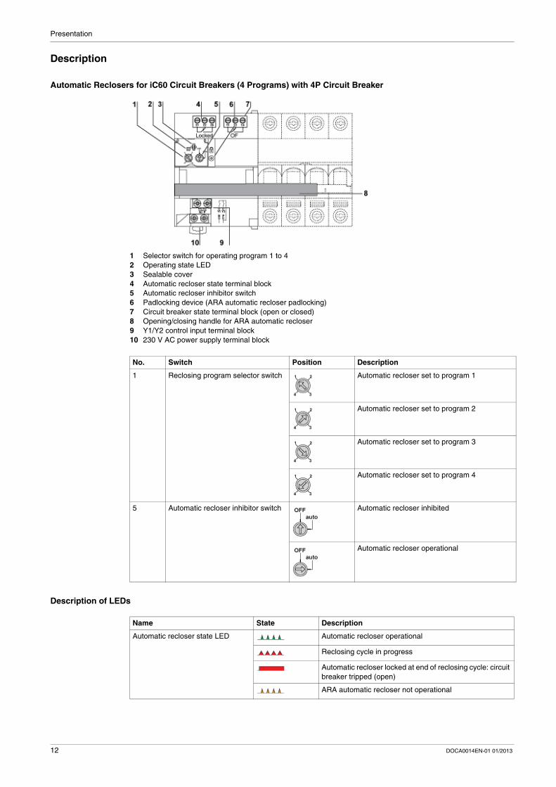
Automatic Reclosers for iC60 Circuit Breakers (4 Programs) with 4P Circuit Breaker
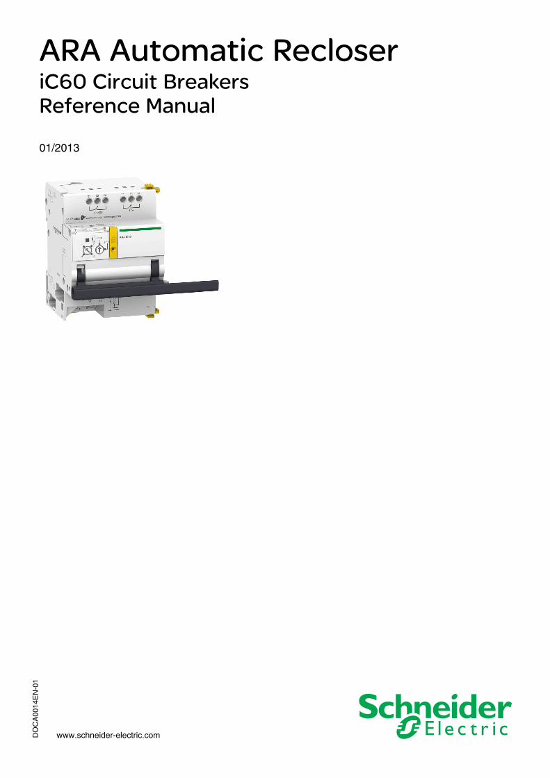
1 Selector switch for operating program 1 to 42 Operating state LED3 Sealable cover4 Automatic recloser state terminal block5 Automatic recloser inhibitor switch6 Padlocking device (ARA automatic recloser padlocking)7 Circuit breaker state terminal block (open or closed)8 Opening/closing handle for ARA automatic recloser9 Y1/Y2 control input terminal block10 230 V AC power supply terminal block
Description of LEDs
No. Switch Position Description
1 Reclosing program selector switch Automatic recloser set to program 1
Automatic recloser set to program 2
Automatic recloser set to program 3
Automatic recloser set to program 4
5 Automatic recloser inhibitor switch Automatic recloser inhibited
Automatic recloser operational
Name State Description
Automatic recloser state LED Automatic recloser operational
Reclosing cycle in progress
Automatic recloser locked at end of reclosing cycle: circuit breaker tripped (open)
ARA automatic recloser not operational
12 DOCA0014EN-01 01/2013
Presentation
Technical Characteristics
General Characteristics
Characteristics Value
Degree of protection (IEC 60529) Device alone IP20
Device in a modular enclosure
IP40 (insulation class II)
Degree of protection (IEC 62262:2002) IK05
Degree of pollution (IEC 60947) 3
Rail mounting DIN 35 mm
Installation position Any
Supply voltage Ue 230 V AC, 50–60 Hz
Insulation voltage Ui phase-neutral: 250 V
Rated impulse withstand voltage Uimp 4 kV (OVC III class 1) 6 kV (OVC III class 2) on the front panel
Operating temperature -25° C to +60° C
Storage temperature -40° C to +85° C
Tropicalization Execution 2(93% relative humidity at +40° C)
Weight 440 g
Mechanical durability (NC/NO) 5000 cycles
Resistance to voltage dips IEC 61 000-4-11 class III
Immunity to power supply frequency variation IEC 61 000-4-28 and IACS E10
Harmonic resistance IEC 61 000-4-13 class 2
Immunity to electrostatic discharge air 8 kV, IEC 61 000-4-2
contacts 4 kV, IEC 61 000-4-2
Immunity to radiated magnetic fields 12 V/m up to 3 GHz, IEC 61 000-4-3
Immunity to fast transients 4 kV from 5 to 100 kHz, IEC 61 000-4-4
Surge immunity IEC 61 000-4-5
Immunity to conducted magnetic fields 10 V from 150 kHz to 80 MHz, IEC 61 000-4-6
Immunity to magnetic fields at line frequency level 4 30 A/m according to IEC 61 000-4-8 and IEC 61 000-4-9
Fire resistance (glow wire) for live parts at 960° C 30 s/30 s according to IEC 60 695-2-10 and IEC 60 695-2-11
for other parts at 650° C 30 s/30 s according to IEC 60 695-2-10 and IEC 60 695-2-11
for handle at 750° C 30 s/30 s according to IEC 60 695-2-10 and IEC 60 695-2-11
Conducted emissions CISPR 11/22
Radiated emissions CISPR 11/22
Resistance to corrosive atmospheres (4-gas test) IEC 60721-3-3 category 3C2
Salt mist Severity 2 according to IEC 60068-2-52
Environment Conforms to RoHS directives, halogen free
DOCA0014EN-01 01/2013 13
Presentation
Control Circuit
Remote Indication/Control
NOTE: The OF and Locked contacts may change state for less than 10 ms. These brief changes of state (bounce) must not be taken into account and must be filtered by a device external to ARA.
Characteristics Value
Control voltage Uc of inputs Y1, Y2 230 V AC (according to IEC 61131)
Duration of command pulse for input Y2
Minimum 200 ms
Maximum –
Maximum response time of input Y2 500 ms
Consumption ≤ 1 W
Inrush consumption 1000 VA for 1P-2P ARA iC601400 VA for 3P-4P ARA iC60
Length of control wires for inputs Y1 and Y2 under 230 V AC cable: 100 m wires in a cable sheath: 500 m
Characteristics Value
Consumption of OF changeover contact output
Minimum 10 mA (24 V AC/DC)
Maximum 1 A (230 V AC)
Consumption of inputs Y1/Y2 230 V AC type 1 according to IEC 61131-2
14 DOCA0014EN-01 01/2013
DOCA0014EN-01 01/2013
2
ARA Automatic Recloser
Installation
DOCA0014EN-01 01/2013
Installation
What Is in This Chapter?
This chapter contains the following topics:
Topic Page
Assembly 16
Connection 20
15
Installation
Assembly
Introduction
The ARA iC60 automatic recloser is used in conjunction with an iC60 circuit breaker.
It is possible to add optional auxiliaries to the iC60 + ARA unit.
Rules for Combination
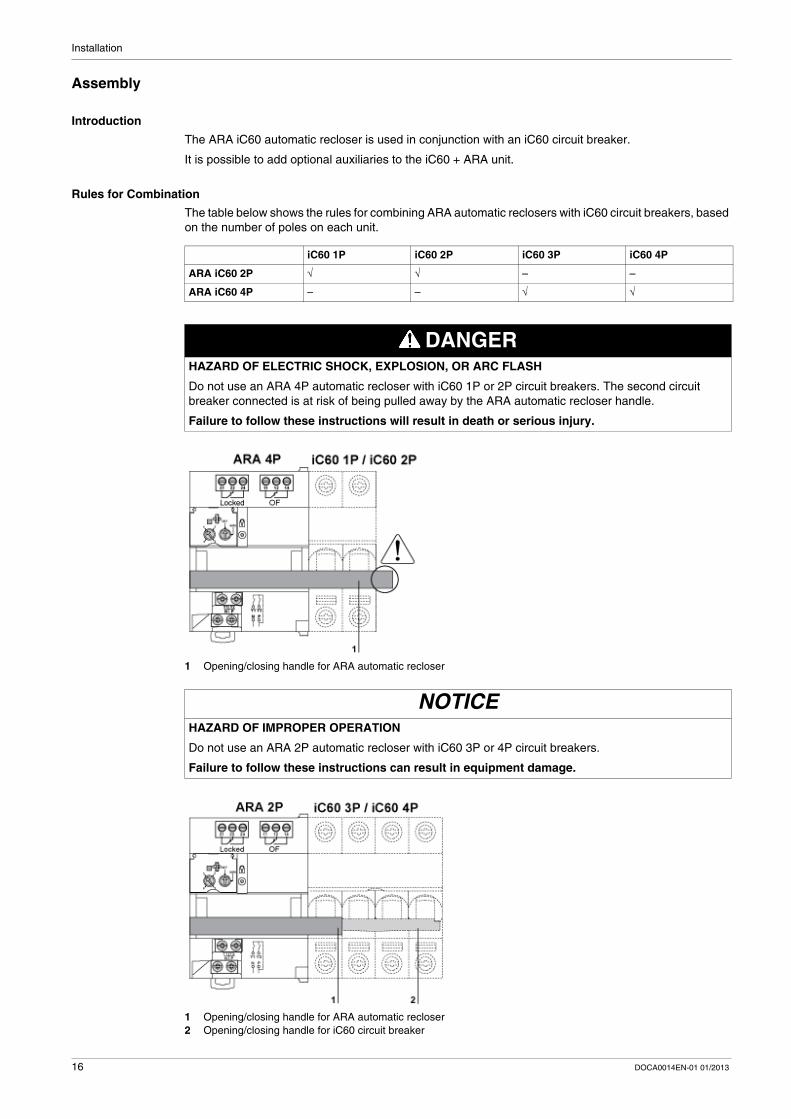
The table below shows the rules for combining ARA automatic reclosers with iC60 circuit breakers, based on the number of poles on each unit.
1 Opening/closing handle for ARA automatic recloser
1 Opening/closing handle for ARA automatic recloser2 Opening/closing handle for iC60 circuit breaker
iC60 1P iC60 2P iC60 3P iC60 4P
ARA iC60 2P √ √ – –
ARA iC60 4P – – √ √
DANGERHAZARD OF ELECTRIC SHOCK, EXPLOSION, OR ARC FLASH
Do not use an ARA 4P automatic recloser with iC60 1P or 2P circuit breakers. The second circuit breaker connected is at risk of being pulled away by the ARA automatic recloser handle.
Failure to follow these instructions will result in death or serious injury.
NOTICEHAZARD OF IMPROPER OPERATION
Do not use an ARA 2P automatic recloser with iC60 3P or 4P circuit breakers.
Failure to follow these instructions can result in equipment damage.
16 DOCA0014EN-01 01/2013
Installation
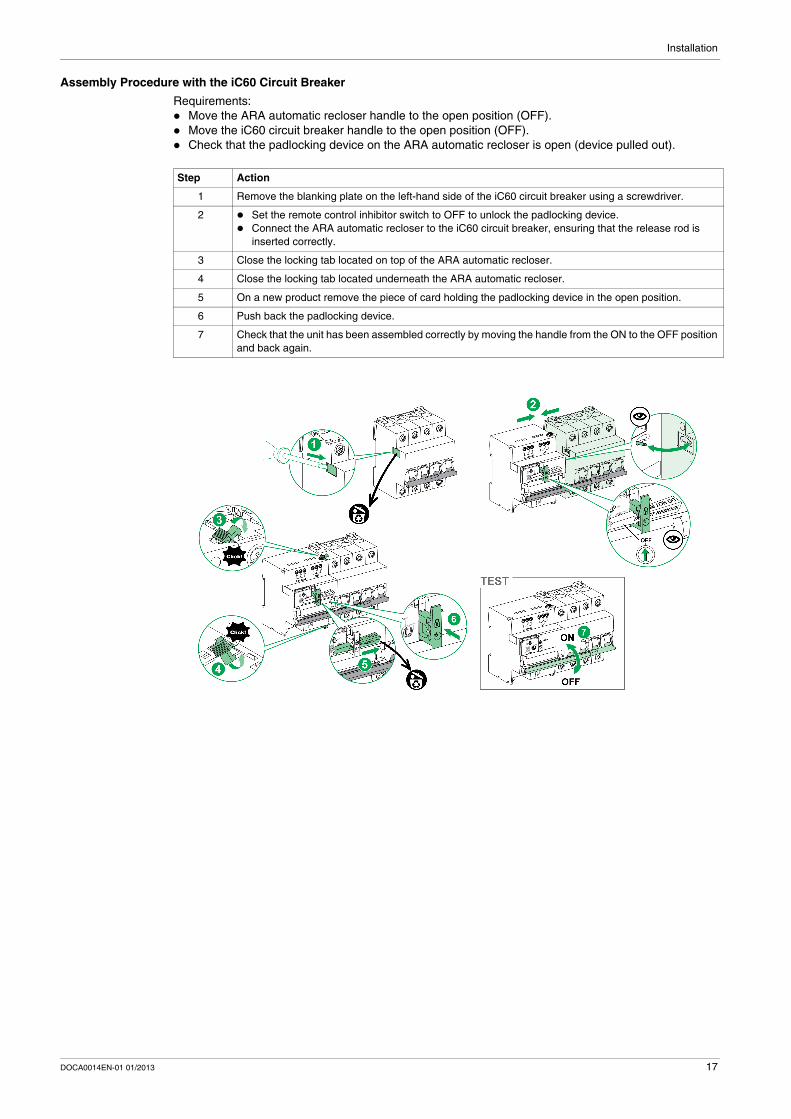
Assembly Procedure with the iC60 Circuit Breaker
Requirements: Move the ARA automatic recloser handle to the open position (OFF). Move the iC60 circuit breaker handle to the open position (OFF). Check that the padlocking device on the ARA automatic recloser is open (device pulled out).
Step Action
1 Remove the blanking plate on the left-hand side of the iC60 circuit breaker using a screwdriver.
2 Set the remote control inhibitor switch to OFF to unlock the padlocking device. Connect the ARA automatic recloser to the iC60 circuit breaker, ensuring that the release rod is
inserted correctly.
3 Close the locking tab located on top of the ARA automatic recloser.
4 Close the locking tab located underneath the ARA automatic recloser.
5 On a new product remove the piece of card holding the padlocking device in the open position.
6 Push back the padlocking device.
7 Check that the unit has been assembled correctly by moving the handle from the ON to the OFF position and back again.
DOCA0014EN-01 01/2013 17
Installation
Assembly with Optional Auxiliaries
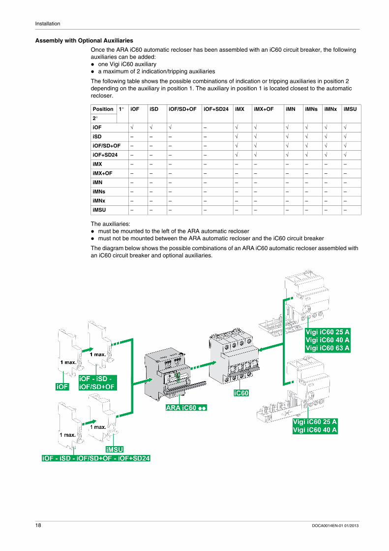
Once the ARA iC60 automatic recloser has been assembled with an iC60 circuit breaker, the following auxiliaries can be added: one Vigi iC60 auxiliary a maximum of 2 indication/tripping auxiliaries
The following table shows the possible combinations of indication or tripping auxiliaries in position 2 depending on the auxiliary in position 1. The auxiliary in position 1 is located closest to the automatic recloser.
The auxiliaries: must be mounted to the left of the ARA automatic recloser must not be mounted between the ARA automatic recloser and the iC60 circuit breaker
The diagram below shows the possible combinations of an ARA iC60 automatic recloser assembled with an iC60 circuit breaker and optional auxiliaries.
Position 1° iOF iSD iOF/SD+OF iOF+SD24 iMX iMX+OF iMN iMNs iMNx iMSU
2°
iOF √ √ √ – √ √ √ √ √ √
iSD – – – – √ √ √ √ √ √
iOF/SD+OF – – – – √ √ √ √ √ √
iOF+SD24 – – – – √ √ √ √ √ √
iMX – – – – – – – – – –
iMX+OF – – – – – – – – – –
iMN – – – – – – – – – –
iMNs – – – – – – – – – –
iMNx – – – – – – – – – –
iMSU – – – – – – – – – –
18 DOCA0014EN-01 01/2013
Installation
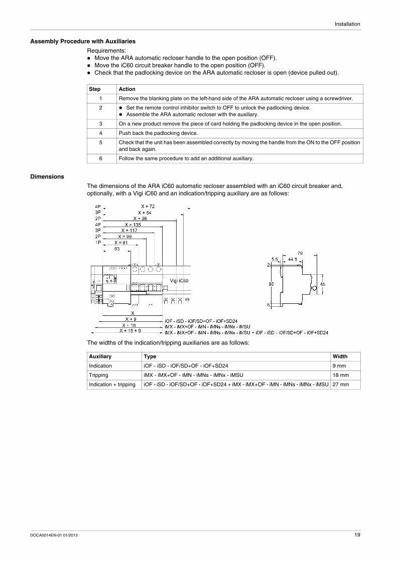
Assembly Procedure with Auxiliaries
Requirements: Move the ARA automatic recloser handle to the open position (OFF). Move the iC60 circuit breaker handle to the open position (OFF). Check that the padlocking device on the ARA automatic recloser is open (device pulled out).
Dimensions
The dimensions of the ARA iC60 automatic recloser assembled with an iC60 circuit breaker and, optionally, with a Vigi iC60 and an indication/tripping auxiliary are as follows:
The widths of the indication/tripping auxiliaries are as follows:
Step Action
1 Remove the blanking plate on the left-hand side of the ARA automatic recloser using a screwdriver.
2 Set the remote control inhibitor switch to OFF to unlock the padlocking device. Assemble the ARA automatic recloser with the auxiliary.
3 On a new product remove the piece of card holding the padlocking device in the open position.
4 Push back the padlocking device.
5 Check that the unit has been assembled correctly by moving the handle from the ON to the OFF position and back again.
6 Follow the same procedure to add an additional auxiliary.
Auxiliary Type Width
Indication iOF - iSD - iOF/SD+OF - iOF+SD24 9 mm
Tripping iMX - iMX+OF - iMN - iMNs - iMNx - iMSU 18 mm
Indication + tripping iOF - iSD - iOF/SD+OF - iOF+SD24 + iMX - iMX+OF - iMN - iMNs - iMNx - iMSU 27 mm
DOCA0014EN-01 01/2013 19
Installation
Connection
Safety Instructions
Connection Blocks
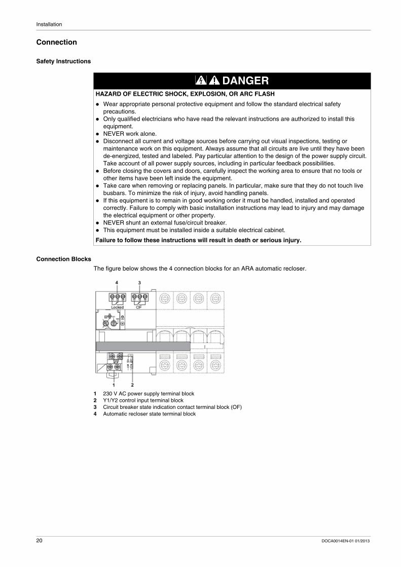
The figure below shows the 4 connection blocks for an ARA automatic recloser.
1 230 V AC power supply terminal block2 Y1/Y2 control input terminal block3 Circuit breaker state indication contact terminal block (OF)4 Automatic recloser state terminal block
DANGERHAZARD OF ELECTRIC SHOCK, EXPLOSION, OR ARC FLASH
Wear appropriate personal protective equipment and follow the standard electrical safety precautions.
Only qualified electricians who have read the relevant instructions are authorized to install this equipment.
NEVER work alone. Disconnect all current and voltage sources before carrying out visual inspections, testing or
maintenance work on this equipment. Always assume that all circuits are live until they have been de-energized, tested and labeled. Pay particular attention to the design of the power supply circuit. Take account of all power supply sources, including in particular feedback possibilities.
Before closing the covers and doors, carefully inspect the working area to ensure that no tools or other items have been left inside the equipment.
Take care when removing or replacing panels. In particular, make sure that they do not touch live busbars. To minimize the risk of injury, avoid handling panels.
If this equipment is to remain in good working order it must be handled, installed and operated correctly. Failure to comply with basic installation instructions may lead to injury and may damage the electrical equipment or other property.
NEVER shunt an external fuse/circuit breaker. This equipment must be installed inside a suitable electrical cabinet.
Failure to follow these instructions will result in death or serious injury.
20 DOCA0014EN-01 01/2013
Installation
Description of Terminals
1, 230 V AC power supply terminal block
2, Y1/Y2 control input terminal block
3, circuit breaker state indication contact terminal block (OF)
4, automatic recloser state terminal block
Connection Characteristics
Connection Scheme
Terminals Function
N Neutral
P Phase
Terminals Function
Y1 Remote inhibition of automatic recloser
Y2 Remote control of final reclosing attempt
Terminals Contact Function
11-12 NC (normally closed) Circuit breaker state: closed
11-14 NO (normally open) Circuit breaker state: open
Terminals Contact Function
21-22 NC (normally closed) Automatic recloser state: locked
21-24 NO (normally open) Automatic recloser state: not locked
No. Terminal block
Tightening torque
Stripping length
Wire size
Solid Flexible Flexible with ferrule
2 cables
1 Power supply (230 V AC)
1 N.m 10 mm 0.5...10 mm² 0.5...6 mm² 0.5 to 4 mm² 0.5 to 2.5 mm²
2 Inputs Y1/Y2
3 NC/NO output 0.7 N.m 8 mm 0.5 to 2.5 mm² 0.5 to 1.5 mm² 0.5 to 1.5 mm²
NOTICERISK OF MALFUNCTION
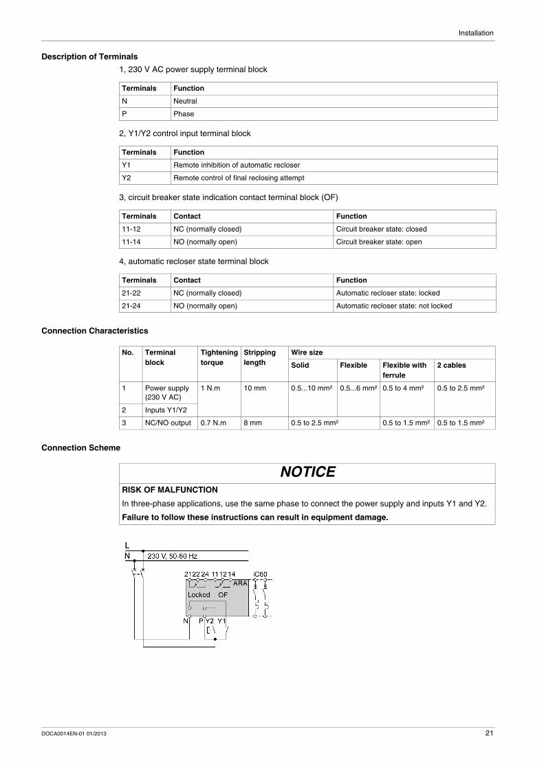
In three-phase applications, use the same phase to connect the power supply and inputs Y1 and Y2.
Failure to follow these instructions can result in equipment damage.
DOCA0014EN-01 01/2013 21
Installation
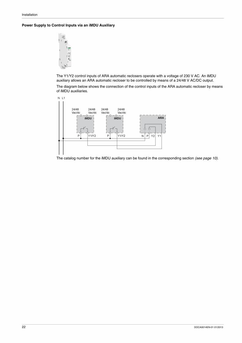
Power Supply to Control Inputs via an iMDU Auxiliary
The Y1/Y2 control inputs of ARA automatic reclosers operate with a voltage of 230 V AC. An iMDU auxiliary allows an ARA automatic recloser to be controlled by means of a 24/48 V AC/DC output.
The diagram below shows the connection of the control inputs of the ARA automatic recloser by means of iMDU auxiliaries.
The catalog number for the iMDU auxiliary can be found in the corresponding section (see page 10).
22 DOCA0014EN-01 01/2013
DOCA0014EN-01 01/2013
3
ARA Automatic Recloser
Usage
DOCA0014EN-01 01/2013
Usage
What Is in This Chapter?
This chapter contains the following topics:
Topic Page
Operation 24
Usage 30
23
Usage
Operation
Introduction
The ARA automatic recloser performs a certain number of reclosing operations depending on the program selected by the user.
The program includes the following settings: A time delay before reclosing (TA) A check time (TB) A maximum number of reclosing attempts (N)
If the fault is still present after these reclosing attempts, the device locks itself out. When the device is locked, the circuit breaker can only be reclosed either manually or by means of a final closing attempt via the Y2 input.
24 DOCA0014EN-01 01/2013
Usage
Operating Principle of the Automatic Recloser
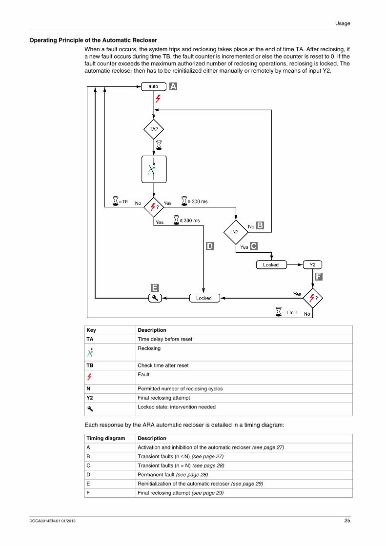
When a fault occurs, the system trips and reclosing takes place at the end of time TA. After reclosing, if a new fault occurs during time TB, the fault counter is incremented or else the counter is reset to 0. If the fault counter exceeds the maximum authorized number of reclosing operations, reclosing is locked. The automatic recloser then has to be reinitialized either manually or remotely by means of input Y2.
Each response by the ARA automatic recloser is detailed in a timing diagram:
Key Description
TA Time delay before reset
Reclosing
TB Check time after reset
Fault
N Permitted number of reclosing cycles
Y2 Final reclosing attempt
Locked state: intervention needed
Timing diagram Description
A Activation and inhibition of the automatic recloser (see page 27)
B Transient faults (n ≤ N) (see page 27)
C Transient faults (n > N) (see page 28)
D Permanent fault (see page 28)
E Reinitialization of the automatic recloser (see page 29)
F Final reclosing attempt (see page 29)
DOCA0014EN-01 01/2013 25
Usage
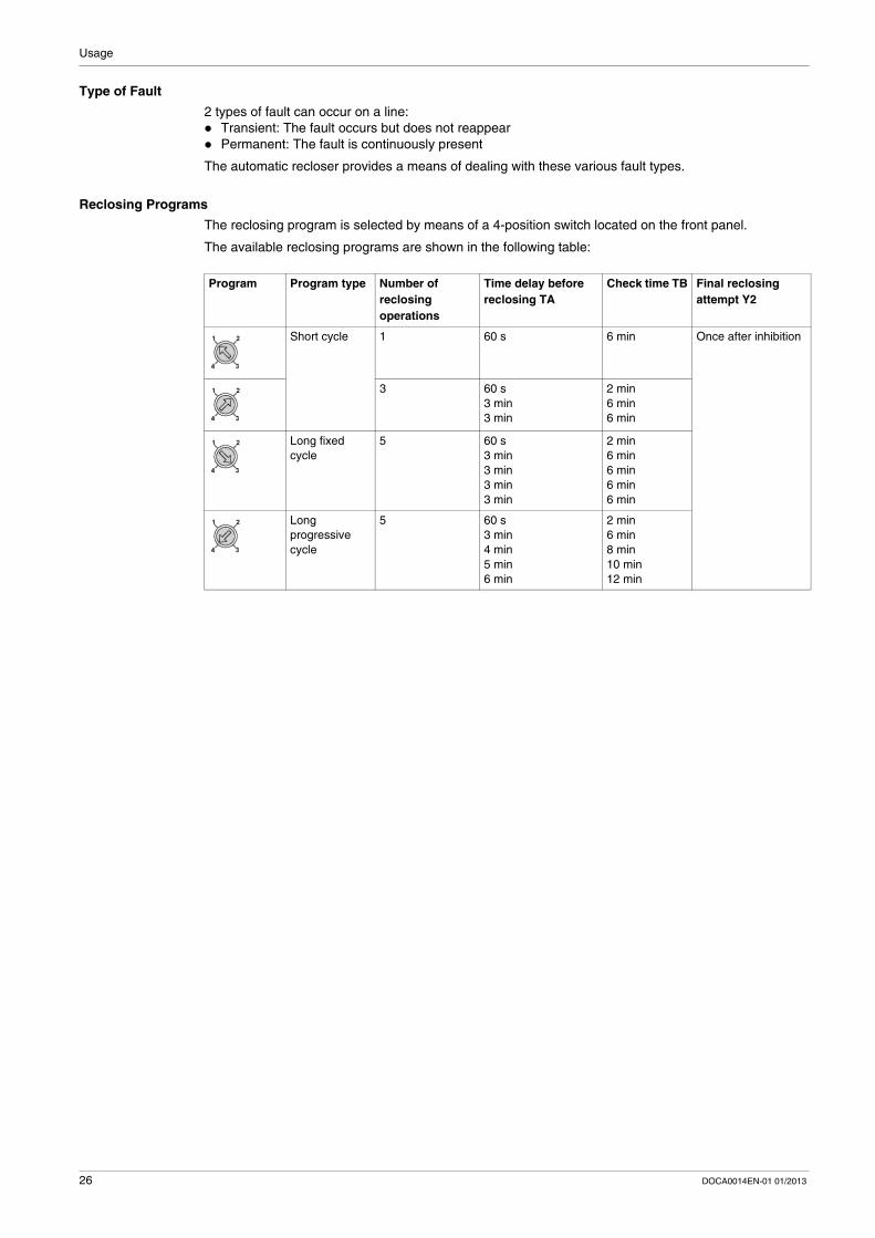
Type of Fault
2 types of fault can occur on a line: Transient: The fault occurs but does not reappear Permanent: The fault is continuously present
The automatic recloser provides a means of dealing with these various fault types.
Reclosing Programs
The reclosing program is selected by means of a 4-position switch located on the front panel.
The available reclosing programs are shown in the following table:
Program Program type Number of reclosing operations
Time delay before reclosing TA
Check time TB Final reclosing attempt Y2
Short cycle 1 60 s 6 min Once after inhibition
3 60 s3 min3 min
2 min6 min6 min
Long fixed cycle
5 60 s3 min3 min3 min3 min
2 min6 min6 min6 min6 min
Long progressive cycle
5 60 s3 min4 min5 min6 min
2 min6 min8 min10 min12 min
26 DOCA0014EN-01 01/2013
Usage
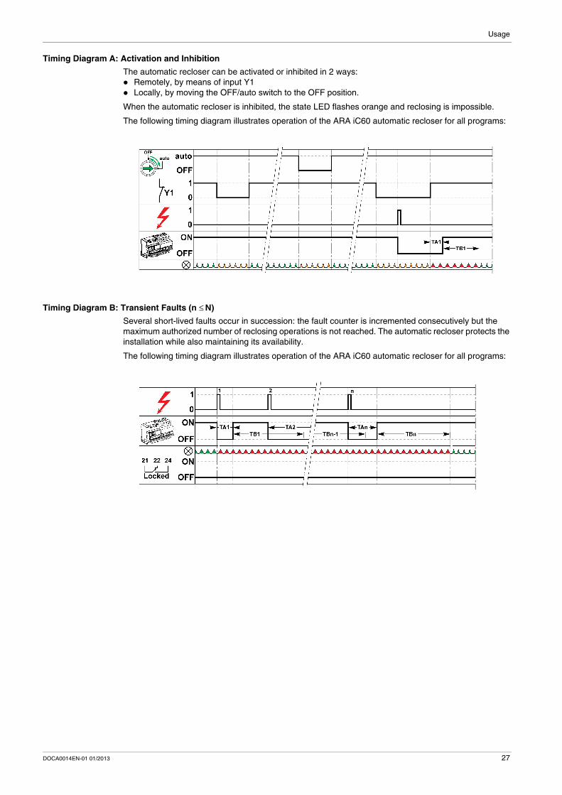
Timing Diagram A: Activation and Inhibition
The automatic recloser can be activated or inhibited in 2 ways: Remotely, by means of input Y1 Locally, by moving the OFF/auto switch to the OFF position.
When the automatic recloser is inhibited, the state LED flashes orange and reclosing is impossible.
The following timing diagram illustrates operation of the ARA iC60 automatic recloser for all programs:
Timing Diagram B: Transient Faults (n ≤ N)
Several short-lived faults occur in succession: the fault counter is incremented consecutively but the maximum authorized number of reclosing operations is not reached. The automatic recloser protects the installation while also maintaining its availability.
The following timing diagram illustrates operation of the ARA iC60 automatic recloser for all programs:
DOCA0014EN-01 01/2013 27
Usage
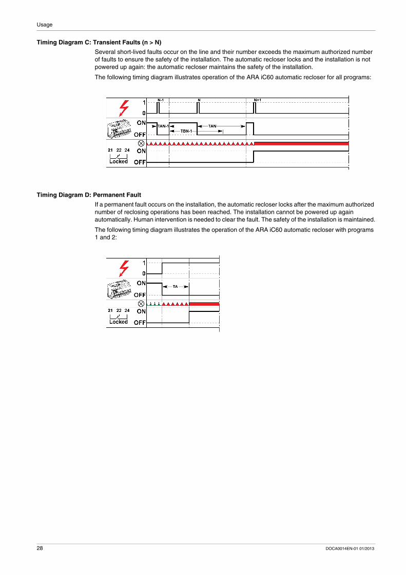
Timing Diagram C: Transient Faults (n > N)
Several short-lived faults occur on the line and their number exceeds the maximum authorized number of faults to ensure the safety of the installation. The automatic recloser locks and the installation is not powered up again: the automatic recloser maintains the safety of the installation.
The following timing diagram illustrates operation of the ARA iC60 automatic recloser for all programs:
Timing Diagram D: Permanent Fault
If a permanent fault occurs on the installation, the automatic recloser locks after the maximum authorized number of reclosing operations has been reached. The installation cannot be powered up again automatically. Human intervention is needed to clear the fault. The safety of the installation is maintained.
The following timing diagram illustrates the operation of the ARA iC60 automatic recloser with programs 1 and 2:
28 DOCA0014EN-01 01/2013
Usage
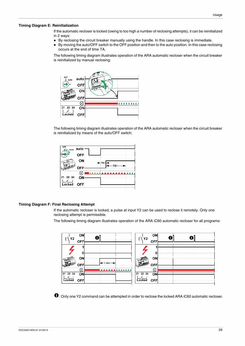
Timing Diagram E: Reinitialization
If the automatic recloser is locked (owing to too high a number of reclosing attempts), it can be reinitialized in 2 ways: By reclosing the circuit breaker manually using the handle. In this case reclosing is immediate. By moving the auto/OFF switch to the OFF position and then to the auto position. In this case reclosing
occurs at the end of time TA.
The following timing diagram illustrates operation of the ARA automatic recloser when the circuit breaker is reinitialized by manual reclosing:
The following timing diagram illustrates operation of the ARA automatic recloser when the circuit breaker is reinitialized by means of the auto/OFF switch:
Timing Diagram F: Final Reclosing Attempt
If the automatic recloser is locked, a pulse at input Y2 can be used to reclose it remotely. Only one reclosing attempt is permissible.
The following timing diagram illustrates operation of the ARA iC60 automatic recloser for all programs:
: Only one Y2 command can be attempted in order to reclose the locked ARA iC60 automatic recloser.
DOCA0014EN-01 01/2013 29
Usage
Usage
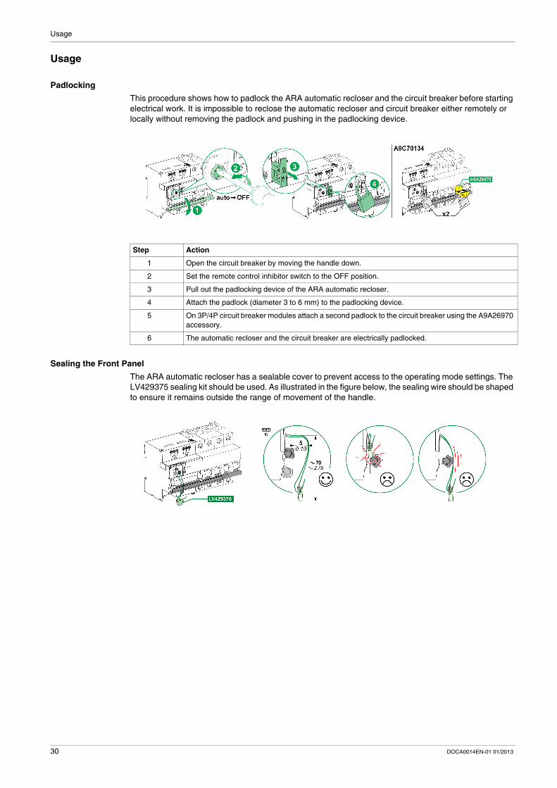
Padlocking
This procedure shows how to padlock the ARA automatic recloser and the circuit breaker before starting electrical work. It is impossible to reclose the automatic recloser and circuit breaker either remotely or locally without removing the padlock and pushing in the padlocking device.
Sealing the Front Panel
The ARA automatic recloser has a sealable cover to prevent access to the operating mode settings. The LV429375 sealing kit should be used. As illustrated in the figure below, the sealing wire should be shaped to ensure it remains outside the range of movement of the handle.
Step Action
1 Open the circuit breaker by moving the handle down.
2 Set the remote control inhibitor switch to the OFF position.
3 Pull out the padlocking device of the ARA automatic recloser.
4 Attach the padlock (diameter 3 to 6 mm) to the padlocking device.
5 On 3P/4P circuit breaker modules attach a second padlock to the circuit breaker using the A9A26970 accessory.
6 The automatic recloser and the circuit breaker are electrically padlocked.
30 DOCA0014EN-01 01/2013
DOCA0014EN-01 01/2013
4
ARA Automatic Recloser
Application example
DOCA0014EN-01 01/2013
Application Example
Application Example for ARA Automatic Recloser
Introduction
The ARA automatic recloser can be used to carry out the following operations: Automatically reclose an iC60 circuit breaker Select a predefined reclosing program to ensure the safety and availability of installations, depending
on the type of installation Padlock the automatic recloser
The ARA automatic recloser increases the availability of installations which are unmonitored, isolated, difficult to access or demand high availability (mobile telephony systems, roads, pumping stations, airports, railways, meteorological stations, service stations, automated teller machines, public lighting, tunnels, etc.). In the case of transient faults (atmospheric disturbance, industrial overvoltages, etc.), availability can be maintained without the need for operator intervention.
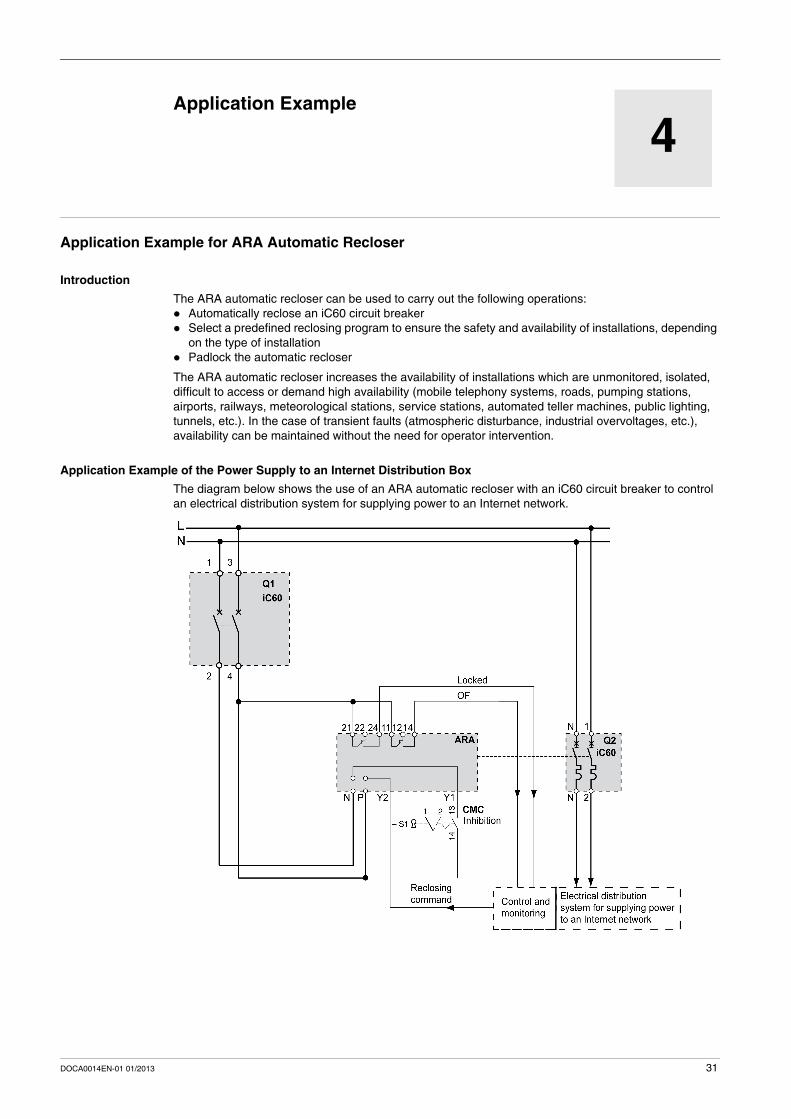
Application Example of the Power Supply to an Internet Distribution Box
The diagram below shows the use of an ARA automatic recloser with an iC60 circuit breaker to control an electrical distribution system for supplying power to an Internet network.
31

As standards, specifications and designs change from time to time, please ask for confirmationof the information given in this publication.
DOCA0014EN-01
Schneider Electric Industries SAS35, rue Joseph MonierCS30323F - 92506 Rueil Malmaison Cedex
www.schneider-electric.com 01/2013