aquasensors datastick measurement system
TRANSCRIPT

Thermo Scientific AquaSensors™ DataStick™ Measurement System User Guide
interchangeable communication adapters
interchangeable sensor heads
universal sensor module
PLC
MODBUSToroidal
Resistivity
Conductivity
Ozone
ORP
Dissolved Oxygen
pH
USB/RS-232
RS-485
ProfiBus
MODBUS
DeviceNet
PDA
PC
SCADA
DCS
PLC
AV38 Local Display 4-20 mA relays

ROSS and the COIL trade dress are trademarks of Thermo Fisher Scientific Inc. U.S. patent 6,793,787.
AQUAfast, Cahn, ionplus, KNIpHE, No Cal, ORION, perpHect, PerpHecT, PerpHecTion, pHISA, pHuture, Pure Water, Sage, Sensing the Future, SensorLink, ROSS, ROSS Ultra, Sure-Flow, Titrator PLUS and TURBO2 are registered trademarks of Thermo Fisher.
1-888-pHAX-ION, A+, All in One, Aplus, AQUAsnap, AssuredAccuracy, AUTO-BAR, AUTO-CAL, AUTO DISPENSER, Auto-ID, AUTO-LOG, AUTO-READ, AUTO-STIR, Auto-Test, BOD AutoEZ, Cable-Free, CERTI-CAL, CISA, DataCOLLECT, DataPLUS, digital LogR, DirectCal, DuraProbe, Environmental Product Authority, Extra Easy/Extra Value, FAST QC, GAP, GLPcal, GLPcheck, GLPdoc, ISEasy, KAP, LabConnect, LogR, Low Maintenance Triode, Minimum Stir Requirement, MSR, NISS, One-Touch, One-Touch Calibration, One-Touch Measurement, Optimum Results, Orion Star, Pentrode, pHuture MMS, pHuture Pentrode, pHuture Quatrode, pHuture Triode, Quatrode, QuiKcheK, rf link, ROSS Resolution, SAOB, SMART AVERAGING, Smart CheK, SMART STABILITY, Stacked, Star Navigator 21, Stat Face, The Enhanced Lab, ThermaSense, Triode, TRIUMpH, Unbreakable pH, Universal Access are trademarks of Thermo Fisher.
Guaranteed Success and The Technical Edge are service marks of Thermo Fisher.
PerpHecT meters are protected by U.S. patent 6,168,707.
PerpHecT ROSS electrodes are protected by U.S. patent 6,168,707.
ORION Series A meters and 900A printer are protected by U.S. patents 5,198,093, D334,208 and D346,753.
ionplus electrodes and Optimum Results solutions are protected by U.S. patent 5,830,338.
ROSS Ultra electrodes are protected by U.S. patent 6,793,787.
ORP standard is protected by U.S. patent 6,350,367.
No Cal electrodes are protected by U.S. patent 7,276,142.
© 2010 Thermo Fisher Scientific Inc. All rights reserved. All trademarks are the property of Thermo Fisher Scientific Inc. and its subsidiaries.
The specifications, descriptions, drawings, ordering information and part numbers within this document are subject to change without notice.
This publication supersedes all previous publications on this subject.

Thermo Scientific AquaSensors™ DataStick™ Measurement System User Guide 1
Preface
This user guide serves to explain the use of the Thermo Scientific AquaSensors DataStick measurement system and is written to cover as many applications as possible. Please do not hesitate to contact Thermo Fisher Scientific or an authorized representative with questions or concerns.
The information presented in this user guide is subject to change without notice as improvements are made, and does not represent any commitment whatsoever on the part of Thermo Fisher Scientific.
Thermo Fisher Scientific cannot accept any responsibility for damage or malfunction of the sensor due to improper use.
Contact Information
To contact Thermo Scientific AquaSensors Technical Support:
Within the United States call 1.800.225.1480 or fax 978-232-6015.
Outside the United States call 978.232.6000 or fax 978.232.6031.
In Europe, the Middle East and Africa, contact your local authorized dealer.
Visit us on the web at www.thermoscientific.com/water

Thermo Scientific AquaSensors™ DataStick™ Measurement System User Guide 2
Safety Information
The Thermo Scientific AquaSensors DataStick measurement system shall be installed and operated only in the manner specified. Only a skilled, trained or authorized person should carry out installation, setup and operation of the system.
Before using the sensor, make sure that the sensor cable is connected as specified. Failure to do so may result in permanent damage to the sensor or controller.
Protection against electric shock will be achieved only by observance of the corresponding installation rules.

Thermo Scientific AquaSensors™ DataStick™ Measurement System User Guide 3
TABLE OF CONTENTS 1 ......................................................................................................................................................................................6 INTRODUCTION
1.1 GENERAL INFORMATION.....................................................................................................................................................................6 1.2 INTENDED USE ..................................................................................................................................................................................7 1.3 SAFETY INSTRUCTIONS ......................................................................................................................................................................7 1.4 SENSOR CALIBRATION AND REFURBISHMENT EXCHANGE PROGRAM.....................................................................................................7 1.5 REMOVAL FROM SERVICE / CORRECT DISPOSAL OF THE SENSOR.........................................................................................................8
1.5.1 Removal from Service ............................................................................................................................................................8 1.5.2 Correct Disposal of Unit..........................................................................................................................................................8
2 PRODUCT DESCRIPTION......................................................................................................................................................................9 3 INSTALLATION.....................................................................................................................................................................................14
3.1 UNPACKING.....................................................................................................................................................................................14 3.2 MOUNTING ......................................................................................................................................................................................14
3.2.1 Pipe Tee Mounting ...............................................................................................................................................................15 3.2.2 Union Mounting ....................................................................................................................................................................16 3.2.3 Immersion Mounting .............................................................................................................................................................17 3.2.4 Sanitary Tee Mounting .........................................................................................................................................................18
3.3 COMMUNICATIONS ADAPTER WIRING ................................................................................................................................................20 3.4 DATASTICK USER INTERFACE OPTIONS ............................................................................................................................................21
3.4.1 Network Host Protocols ........................................................................................................................................................21 3.4.2 AV38 Local Display ..............................................................................................................................................................21 3.4.3 AquaComm™ Windows Software.......................................................................................................................................22 ®
3.4.4 Open Protocol Commands ...................................................................................................................................................23
4 MEASUREMENTS.................................................................................................................................................................................24 4.1 DIFFERENTIAL PH MEASUREMENT ....................................................................................................................................................25
4.1.1 pH Interface Overview ..........................................................................................................................................................26 4.1.2 pH Configuration...................................................................................................................................................................26 4.1.3 pH Calibration.......................................................................................................................................................................30 4.1.4 pH Sensor Diagnosis............................................................................................................................................................38 4.1.5 pH Sensor Maintenance .......................................................................................................................................................39
4.2 DIFFERENTIAL ORP MEASUREMENT .................................................................................................................................................42 4.2.1 ORP Interface Overview.......................................................................................................................................................42 4.2.2 ORP Configuration ...............................................................................................................................................................43 4.2.3 ORP Calibration....................................................................................................................................................................45 4.2.4 ORP Sensor Maintenance....................................................................................................................................................47 4.2.5 ORP Spare Parts..................................................................................................................................................................49
4.3 TWO ELECTRODE CONDUCTIVITY AND RESISTIVITY............................................................................................................................49 4.3.1 Contacting Conductivity/Resistivity Overview.......................................................................................................................49 4.3.2 Configuration of Contacting Conductivity Sensors ...............................................................................................................50 4.3.3 Contacting Conductivity Calibration......................................................................................................................................62 4.3.4 Contacting Conductivity Maintenance ..................................................................................................................................65
4.4 TOROIDAL CONDUCTIVITY ................................................................................................................................................................66 4.4.1 Toroidal Conductivity Overview ............................................................................................................................................66 4.4.2 Configuration of Toroidal Sensors ........................................................................................................................................67 4.4.3 Toroidal Conductivity Calibration..........................................................................................................................................78 4.4.4 Toroidal Conductivity Maintenance ......................................................................................................................................81
4.5 DISSOLVED OXYGEN (PPM AND PPB) AND OZONE ...........................................................................................................................82 4.5.1 Dissolved Oxygen / Ozone Interface Overview ....................................................................................................................82 4.5.2 Configuration of Dissolved Oxygen and Ozone Sensor Heads............................................................................................83

Thermo Scientific AquaSensors™ DataStick™ Measurement System User Guide 4
4.5.3 Dissolved Oxygen Calibration ..............................................................................................................................................87 4.5.4 Dissolved Oxygen Maintenance ...........................................................................................................................................91
4.6 TURBIDITY.......................................................................................................................................................................................91 4.6.1 Drinking Water Turbidity .......................................................................................................................................................92 4.6.2 Wide-Range Turbidity Measurement System.......................................................................................................................92
4.7 TEMPERATURE CALIBRATION............................................................................................................................................................93 5 DIAGNOSTICS AND TROUBLESHOOTING........................................................................................................................................95
5.1 DIAGNOSTICS ..................................................................................................................................................................................95 5.2 TROUBLESHOOTING .........................................................................................................................................................................96
5.2.1 pH Sensor Head inspection..................................................................................................................................................97 5.2.2 ORP Sensor Head inspection...............................................................................................................................................97 5.2.3 Dissolved Oxygen and Ozone Sensor Head inspection.......................................................................................................98 5.2.4 Contacting Conductivity Sensor Head inspection.................................................................................................................98 5.2.5 Toroidal Conductivity Sensor Head inspection.....................................................................................................................98
6 PROGRAMMING GUIDE - COMMANDS AND RESPONSES..............................................................................................................99 7 FREE CHLORINE CONCENTRATION CALCULATION ....................................................................................................................107 8 COMPLIANCE INFORMATION...........................................................................................................................................................109 9 LIMITED WARRANTY.........................................................................................................................................................................110 10 TERMS AND CONDITIONS ................................................................................................................................................................111

Thermo Scientific AquaSensors™ DataStick™ Measurement System User Guide 5
Tables of Figures and Tables
Table of Figures
Figure Number and Caption Page Number
Figure 1: Three Parts of the DataStick 9
Figure 2: The Universal Body 10
Figure 3: Full Array of DataStick Options 10
Figure 4: Configured Analytical Measurements 11
Figure 5: Drinking Water Turbidity System 11
Figure 6: DataStick Interface Options 12
Figure 7: Communications Adapter 12
Figure 8: Mounting Hardware Overview 13
Figure 9: The inner workings of the User-Entered Concentration Table. 61
Figure 10: The inner workings of the User-Entered Concentration Table. 77
Table of Tables
Table Number and Description Page Number
Table 1: 10 Point Conductivity Vs. Concentration Table 57
Table 2: Concentration Vs Conductivity after Editing 60
Table 3: 10 Point Conductivity Vs. Concentration Table 73
Table 4: Concentration Vs Conductivity after Editing 76
Table 5: Data Reporting 99
Table 6: Change Measurement Configuration Settings 100
Table 7: View Configuration Settings 101
Table 8: Calibration Commands 102
Table 9: Diagnostics and System Information 105

Thermo Scientific AquaSensors™ DataStick™ Measurement System User Guide 6
1 INTRODUCTION 1.1 General Information
Thank you for purchasing the Thermo Scientific AquaSensors DataStick Analytical Measurement System. This is a very robust and versatile product intended for continuous use in industrial applications and complies with safety regulations currently in force. Unique features include:
• Pre-calibrated sensors for plug and play capability.
• Direct connection to computer control systems without the need for analyzer electronics boxes.
• Sensor heads are easily serviced and replaced in the field minimizing downtime.
• Any sensor type in the DataStick family can be used with any DataStick thus making it possible to convert a measurement point from pH to toroidal conductivity (for instance), simply by changing sensor heads.
• Performance is not affected by cable length and can be run up to 3,000 feet depending on the selected communications protocol.
Thermo Fisher Scientific does not accept any liability for damage that may arise if information in this user guide is not followed. Therefore, the operating instructions and specifications must be read and understood by all persons involved in installation and operation of this equipment.
This user guide identifies safety instructions and additional information by means of the following symbols:
This symbol draws attention to safety instructions and warnings of potential danger, which if neglected, could result in injury to persons and/or damage to property.
This symbol identifies additional information and instructions, which if neglected, could lead to inefficient operation and possible loss of production.
It is recommended that this user guide be made accessible to everyone who may need it as a reference.
Please contact Thermo Fisher Scientific or an authorized representative with any questions.

Thermo Scientific AquaSensors™ DataStick™ Measurement System User Guide 7
1.2 Intended Use
The DataStick Analytical System is designed for continuous industrial applications. Interchangeable measurement and communications components allow for quick replacement or reconfiguration.
Any other use, or use not mentioned here, that is incompatible with the technical specifications is deemed inappropriate. The operator is solely responsible for any damage arising from such use.
Other prerequisites for appropriate use include:
• Observing the instructions, notes and requirements set out in this user guide.
• Observing all local safety regulations.
• Observing all warnings and cautions in the documentation regarding all products used in this measurement system, including the sensor, mounting hardware, and cabling.
• Observing the prescribed environmental and operational conditions.
• Observing chemical compatibility with all wetted materials.
1.3 Safety Instructions
The DataStick Analytical System should be installed and operated only by personnel familiar with the sensor and qualified for such work.
A defective sensor should be returned to Thermo Fisher Scientific for repair or replacement. Contact Thermo Fisher Scientific to obtain a Return Material Authorization (RMA) number.
No modifications to the DataStick Analytical System components are allowed. The manufacturer/ supplier accepts no responsibility for damage caused by unauthorized modifications. The risk is borne entirely by the user.
1.4 Sensor Calibration and Refurbishment Exchange Program DataStick sensor heads are pre-calibrated and can be exchanged in the field to maintain accuracy. Thermo Fisher Scientific provides service to refurbish and calibrate used sensors and return them for service. Please call the factory to inquire about the program.

Thermo Scientific AquaSensors™ DataStick™ Measurement System User Guide 8
The following advisories and warnings must be followed with all DataStick Products:
1.5 Removal from Service / Correct Disposal of the Sensor
1.5.1 Removal from Service d for doing this will depend on the termination hardware that is chosen. In the case of a USB
bserve the local environmental regulations for correct disposal.
Disconnect the cable wiring. The methoconnection, just remove the connector. In the case of a screw terminal block, remove the black ground wire last.
Remove the sensor from the mounting hardware.
1.5.2 Correct Disposal of Unit When the sensor is taken out of service, o
This equipment is suitable for use in Class I, Division 2, Groups A, B, C, d or Non-Hazardous Locations Only
The equipment shall be supplied from a Class 2 power input.
The supply is from an isolated source, maximum 30 VDC.
DataStick bodies constructed from polymeric materials Noveon Corzan Type 3218 shall not be used in applications exceeding a maximum operating ambient of 50C.
Input and output wiring must be in accordance with Class I, Div.2 wiring methods and in accordance with the authority having jurisdiction.
Warning: Explosion Hazard – Substitution of components may impair suitability for Class I, Division 2.
Warning – Explosion Hazard – Do not disconnect equipment unless power has been switched off or the area is known to be non-hazardous.

Thermo Scientific AquaSensors™ DataStick™ Measurement System User Guide 9
2 PRODUCT DESCRIPTION The DataStick analytical measurement system consists of three highly customizable parts designed for direct connection to control systems without the need for intermediate analyzer electronics. A communications adapter plugs into the back of the system and provided direct interactive communication of measurement, configuration, calibration and diagnostic information with computers and networks. A full family of sensor heads plug into the front of the system and automatically provide calibrated high-resolution measurements.
Please refer to performance specifications in parameter specific datasheets.
Figure 1: Three Parts of the DataStick
Communications Adapter Provides power and direct interactive communication with control systems and computers.
Communications Selections: RS-232 ASCII, RS-232 DF1, RS-485 MODBUS, PROFIBUS, DEVICENET, ETHERNET, USB, WIRELESS…
Body Material: 316-Stainless Steel, CPVC, Ryton®, PEEK® Cable length and termination: 10 feet to 1000 feet
(Consult the factory for other material choices).
DataStick Sensor Head Pre-calibrated sensor heads can be replaced at any time.
Sensor head offering includes:
Two electrode conductivity, two electrode resistivity, toroidal conductivity, differential pH, differential ORP, dissolved oxygen, turbidity and ozone.
New sensor parameters are continually being added to the DataStick family. Check with the factory for a complete list.
DataStick Sensor Body Universal conversion of sensor signals. Interactive communication for data reporting, configuration and calibration.
Insertion, submersion and sanitary fittings.
Body Material: 316-Stainless Steel, CPVC, Ryton®, PEEK®
(Consult the factory for other material choices).

Thermo Scientific AquaSensors™ DataStick™ Measurement System User Guide 10
The heart of the DataStick measurement system is a 1-inch tube body with encapsulated measurement electronics that automatically convert sensor signals into calibrated engineering units. This single tube body in essence takes the place of a full family of analyzer electronics boxes. The DataStick works seamlessly with a variety of communications adapters so that it can operate directly with any computer system. These features allow for quick changes to the measurement system without significant down time.
Figure 2: The Universal Body
This family of plug and play communications adapters and sensor heads makes the DataStick the most versatile and accurate analytical measurement system on the market. Any sensor type can be plugged in to obtain calibrated data. Any computer system can be set up to communicate directly by configuring the DataStick system with the appropriate communications adapter. If local display and standard 4-20 milliamp data reporting is desired then the DataStick can be connected to Thermo Scientific AquaSensors AV38 Local display as shown in the upper left corner of Figure 3. The AV38 can work with multiple DataSticks running the Modbus protocol.
Figure 3: Full Array of DataStick Options
DataStick system components can be exchanged in the field. Sensor heads will remain calibrated when moved from one DataStick to another making it possible to perform calibrations in the laboratory and then just exchange sensor heads in the field. Systems are shown here in stainless steel and PEEK® but are also offered in Ryton® and CPVC for a wide spectrum of applications.
1-inch NPT Threads (Immersion)
Insert sensor head this end.
1-inch NPT Threads (Insertion)
Flat for sanitary adapters
Insert communications adapter this end. Wrench Flats

Thermo Scientific AquaSensors™ DataStick™ Measurement System User Guide 11
Dissolved Oxygen and Ozone Series
Interchangeable pre-calibrated sensor heads make it possible to quickly configure a DataStick for any application with a full series of analytical measurements as shown in Figure 4.
Figure 4: Configured Analytical Measurements
DataStick systems can also be configured into more complex systems. Drinking water turbidity measurements are provided using a DataStick installed in a specially designed sample chamber that has a white light source in the lid. The system provides very accurate turbidity measurements that can be calibrated and configured locally using the AV38 display or it can be networked directly to a computer system for measurement, calibration, configuration and diagnostics.
Figure 5: Drinking Water Turbidity System
Differential pH Series ORP Series
Two Electrode Conductivity Series
Toroidal Conductivity Series
Turbidity 0 to 4000 NTU

Thermo Scientific AquaSensors™ DataStick™ Measurement System User Guide 12
Schematically as shown in Figure 6, any DataStick system can be connected directly to a computer network to obtain 24 bit data and interactive measurement, configuration, calibration and diagnostic capability.
Figure 6: DataStick Interface Options
Interchangeable communications adapters currently supported include:
Communications Adapter Suggested Application Standard Software Interface Reference
USB ASCII Laboratory PC
Field Diagnostics with Laptop AquaComm™, HyperTerminal ASCII Commands and Responses shown
in the appendix of this user guide.
RS-232 ASCII Laboratory PC AquaComm™, HyperTerminal ASCII Commands and Responses shown in the appendix of this user guide.
Modbus RTU over RS-232 or RS-485
AV38 Local Display
PLC with Modbus Network AquaComm™, ModScan32
AV38 User guide
Modbus Communications User guide
DeviceNet PLC with DeviceNet Network DeviceNet PLC Tools DeviceNet Communications User guide
Electronic Data Sheet (EDS file)
CANopen PLC with CANopen Network CANopen PLC Tools CANopen Communications User guide
Profibus DP V1 PLC with Profibus Network Profibus Gateway Tools Modbus/Profibus Gateway User guide
Ethernet/IP Web connected Web ready Ethernet User guide
Figure 7: Communications Adapter
PC, PLC, DCS or PDA
Power: 24VDC or 120/240 VAC
2 Isolated mA Loops
2 Form C Relays
Modbus
DataStick
AV38 Local Display
Digital Gateway
Digital Gateway

Thermo Scientific AquaSensors™ DataStick™ Measurement System User Guide 13
DataStick systems use 1-inch NPT threads for insertion and immersion applications. The threads on the back-body are used for submersion and Thermo Scientific AquaSensors Union Mount hardware and the front threads are used for insertion into standard plumbing tees. A variety of sanitary mounts are available with DataSticks that have a special retaining ring just below the hex flats. PEEK® sensor heads with sanitary face seals should be used in sanitary applications along with stainless steel sensor bodies that have special mounting rings between the wrench flats and the NPT threads.
Figure 8: Mounting Hardware Overview
Use a 1-¼ inch wrench to turn the sensor body into pipe fittings that have internal 1-inch NPT threads. Use Teflon tape on all threads to insure a proper seal. Do not use liquid thread compounds on DataStick threads.
Use the back threads of DataStick for extension pipes. Integral junction boxes are used for wire termination. For Sanitary applications use
Thermo Scientific AquaSensors fittings.
Use special Thermo Scientific AquaSensors Union Mount fittings for applications that require frequent removal for calibration.
Use the front threads for insertion into pipe tees.
Submersion
Sanitary
Union Mount
Tee Mount
Ball Valve For applications requiring extraction in a pressurized line
Thermo Scientific AquaSensors™ DataStick™ Measurement System User Guide 14
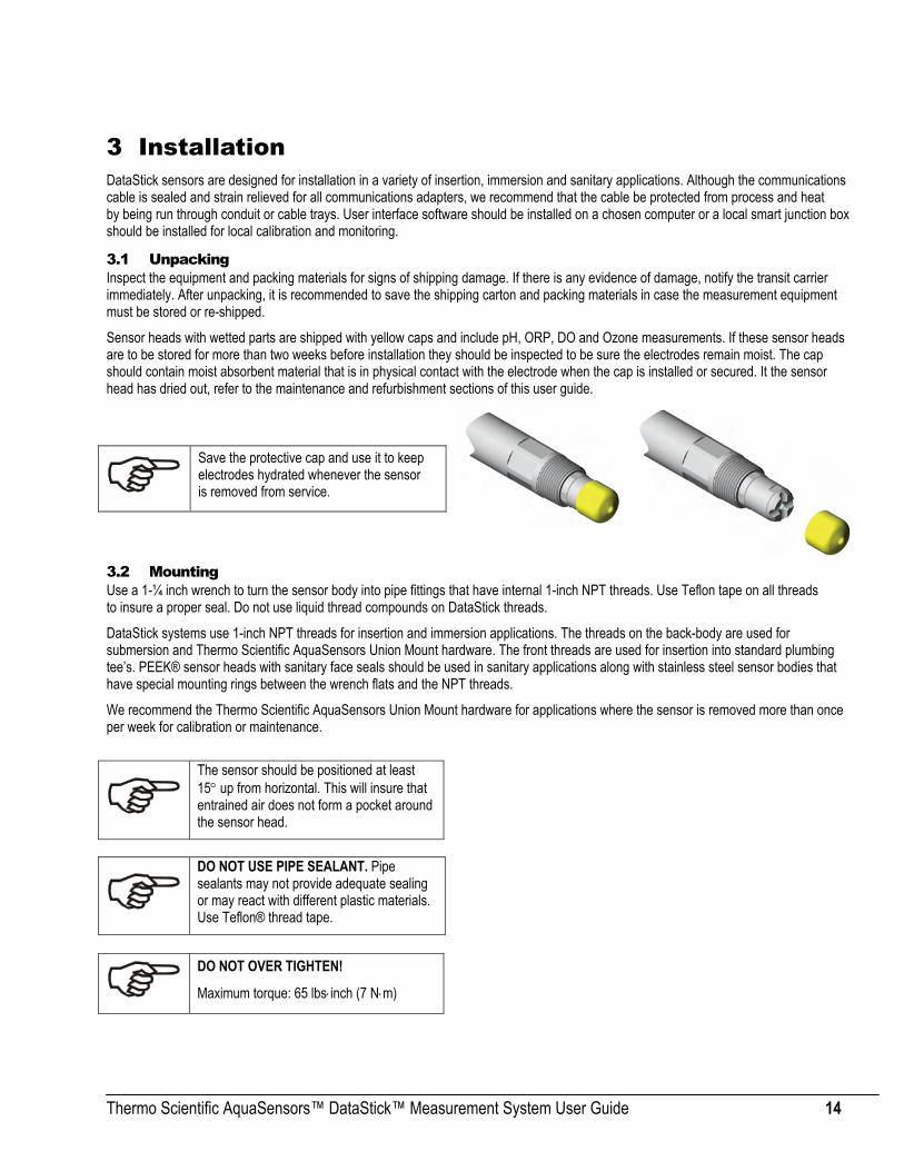
3 Installation DataStick sensors are designed for installation in a variety of insertion, immersion and sanitary applications. Although the communications cable is sealed and strain relieved for all communications adapters, we recommend that the cable be protected from process and heat by being run through conduit or cable trays. User interface software should be installed on a chosen computer or a local smart junction box should be installed for local calibration and monitoring.
3.1 Unpacking Inspect the equipment and packing materials for signs of shipping damage. If there is any evidence of damage, notify the transit carrier immediately. After unpacking, it is recommended to save the shipping carton and packing materials in case the measurement equipment must be stored or re-shipped.
Sensor heads with wetted parts are shipped with yellow caps and include pH, ORP, DO and Ozone measurements. If these sensor heads are to be stored for more than two weeks before installation they should be inspected to be sure the electrodes remain moist. The cap should contain moist absorbent material that is in physical contact with the electrode when the cap is installed or secured. It the sensor head has dried out, refer to the maintenance and refurbishment sections of this user guide.
3.2 Mounting Use a 1-¼ inch wrench to turn the sensor body into pipe fittings that have internal 1-inch NPT threads. Use Teflon tape on all threads to insure a proper seal. Do not use liquid thread compounds on DataStick threads.
DataStick systems use 1-inch NPT threads for insertion and immersion applications. The threads on the back-body are used for submersion and Thermo Scientific AquaSensors Union Mount hardware. The front threads are used for insertion into standard plumbing tee’s. PEEK® sensor heads with sanitary face seals should be used in sanitary applications along with stainless steel sensor bodies that have special mounting rings between the wrench flats and the NPT threads.
We recommend the Thermo Scientific AquaSensors Union Mount hardware for applications where the sensor is removed more than once per week for calibration or maintenance.
Save the protective cap and use it to keep electrodes hydrated whenever the sensor is removed from service.
The sensor should be positioned at least 15° up from horizontal. This will insure that entrained air does not form a pocket around the sensor head.
DO NOT USE PIPE SEALANT. Pipe sealants may not provide adequate sealing or may react with different plastic materials. Use Teflon® thread tape.
DO NOT OVER TIGHTEN!
Maximum torque: 65 lbs⋅inch (7 N⋅m)
Thermo Scientific AquaSensors™ DataStick™ Measurement System User Guide 15
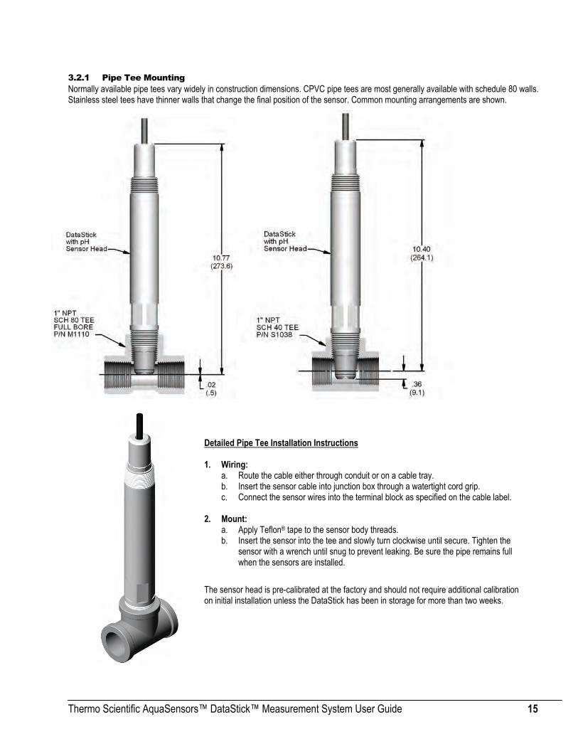
3.2.1 Pipe Tee Mounting Normally available pipe tees vary widely in construction dimensions. CPVC pipe tees are most generally available with schedule 80 walls. Stainless steel tees have thinner walls that change the final position of the sensor. Common mounting arrangements are shown.
Detailed Pipe Tee Installation Instructions 1. Wiring:
a. Route the cable either through conduit or on a cable tray. b. Insert the sensor cable into junction box through a watertight cord grip. c. Connect the sensor wires into the terminal block as specified on the cable label.
2. Mount: a. Apply Teflon® tape to the sensor body threads. b. Insert the sensor into the tee and slowly turn clockwise until secure. Tighten the
sensor with a wrench until snug to prevent leaking. Be sure the pipe remains full when the sensors are installed.
The sensor head is pre-calibrated at the factory and should not require additional calibration on initial installation unless the DataStick has been in storage for more than two weeks.

Thermo Scientific AquaSensors™ DataStick™ Measurement System User Guide 16
3.2.2 Union Mounting Union mount hardware makes it easy to remove and insert the sensor for applications where calibration and/or cleaning are frequent.
Union Mount Advantages:
• Optimal positioning of sensing surface.
• Trouble-free installation.
• Quick disconnect.
• No cable twisting during installation.
• Easy maintenance.
Detailed Union Mount Installation Instructions 1. Wiring:
a. Apply Teflon® tape to the rear sensor body threads and pass the cable through the adapter. Thread the adapter onto the sensor clockwise until it is secure.
b. Pass the union collar over the cable and onto the adapter with the threads facing the front of the sensor. c. Route the cable either through conduit or on a cable tray. d. Insert the sensor cable into the junction box through a watertight cord grip. e. Connect the sensor wires into the terminal block as specified on the cable label.
2. Mount: a. Assemble the lower portion of the mounting hardware by threading the pipe nipple into the threaded flange and the tee.
Apply Teflon® tape to the threads. b. Inspect the O-ring on the union-mounting threaded flange for imperfections or particles of dirt that may prevent the O-ring seal
from seating properly. c. Carefully insert the sensor into the Thermo Scientific AquaSensors union-mounting tee. Turning the retaining collar clockwise
and hand tighten until snug. Be sure the pipe remains full when the sensor is installed.
Thermo Scientific AquaSensors™ DataStick™ Measurement System User Guide 17
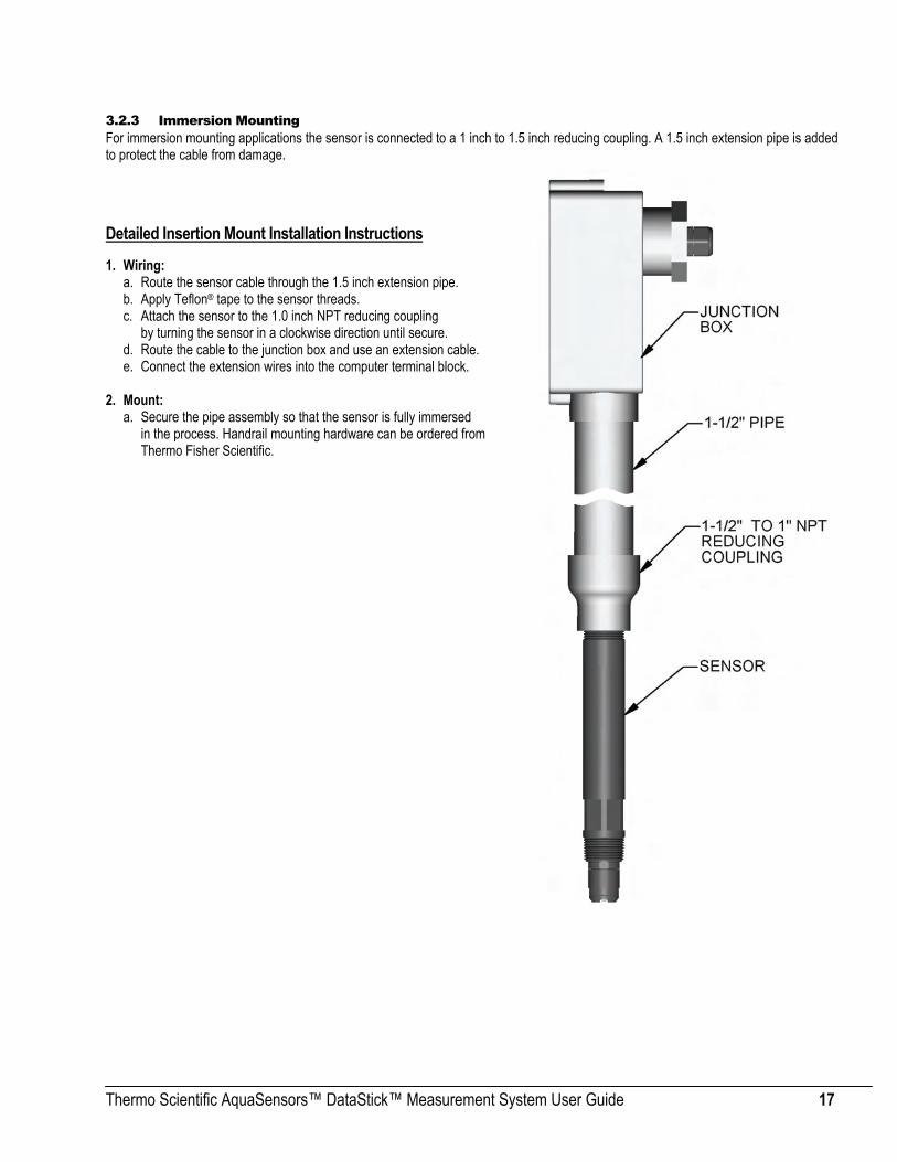
3.2.3 Immersion Mounting For immersion mounting applications the sensor is connected to a 1 inch to 1.5 inch reducing coupling. A 1.5 inch extension pipe is added to protect the cable from damage.
Detailed Insertion Mount Installation Instructions 1. Wiring:
a. Route the sensor cable through the 1.5 inch extension pipe. b. Apply Teflon® tape to the sensor threads. c. Attach the sensor to the 1.0 inch NPT reducing coupling
by turning the sensor in a clockwise direction until secure. d. Route the cable to the junction box and use an extension cable. e. Connect the extension wires into the computer terminal block.
2. Mount:
a. Secure the pipe assembly so that the sensor is fully immersed in the process. Handrail mounting hardware can be ordered from Thermo Fisher Scientific.

Thermo Scientific AquaSensors™ DataStick™ Measurement System User Guide 18
3.2.4 Sanitary Tee Mounting For sanitary mounting applications the sensor is connected to an adapter with a retaining collar and clamped into a short-branch sanitary tee.
Detailed Sanitary Mount Installation Instructions Wiring:
a. Thread the retaining collar over the cable and onto the sensor with the threads facing the front of the sensor.
b. Route the cable either through conduit or on a cable tray. c. Insert the sensor cable into the junction box through
a watertight cord grip. d. Connect the sensor wires into the terminal block as shown
on the cable label. Mount:
a. Insert the sensor into the adapter making sure the front o-ring on the sensor is seated.
b. Thread the retaining collar into the adapter and tighten with a wrench until the face of the sensor head is flush with the adapter and the o-ring forms a seal.
c. Place a sanitary gasket on the branch flange. d. Insert the sensor with the adapter into the branch of the tee;
be sure the pipe remains full while installing to minimize trapped air. e. Install and tighten the sanitary clamp to retain the sensor and
adapter in the tee.

Thermo Scientific AquaSensors™ DataStick™ Measurement System User Guide 19
Insertion Mounting Hardware (Ball valve) The Thermo Scientific AquaSensors Insertion Mounting Hardware allows the DataStick measurement system to be inserted and extracted from a pressurized process line without stopping the flow in the pipe. The mounting hardware is available in user guide and air/water assisted units in both Stainless Steel and CPVC. The air/water assisted mounting hardware is fitted with a 3-way control for air or water assist with a maximum pressure of 120 psi. The user guide mounting hardware does not have a valve but a drain valve may be added by replacing the ¼” NPT plug with a valve.
Maximum pressure for the insertion mounting hardware is determined by the material, construction and maximum temperature. Please consult the Insertion Mounting Hardware User guide for details.
Please refer to Insertion Mounting Hardware User guide for detailed instructions.
Thermo Scientific AquaSensors™ DataStick™ Measurement System User Guide 20
Partial List of Available Adapters
Potted Serial number and Part number.
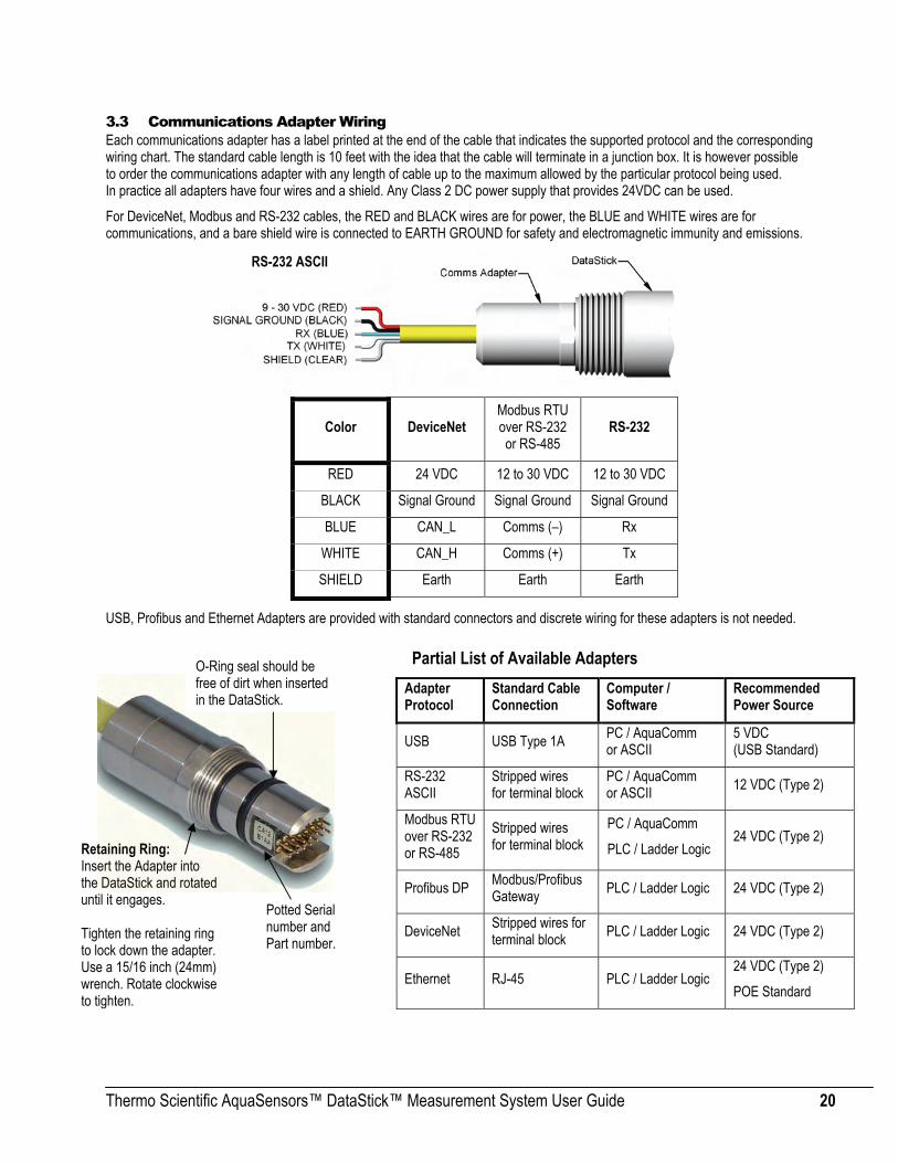
3.3 Communications Adapter Wiring Each communications adapter has a label printed at the end of the cable that indicates the supported protocol and the corresponding wiring chart. The standard cable length is 10 feet with the idea that the cable will terminate in a junction box. It is however possible to order the communications adapter with any length of cable up to the maximum allowed by the particular protocol being used. In practice all adapters have four wires and a shield. Any Class 2 DC power supply that provides 24VDC can be used.
For DeviceNet, Modbus and RS-232 cables, the RED and BLACK wires are for power, the BLUE and WHITE wires are for communications, and a bare shield wire is connected to EARTH GROUND for safety and electromagnetic immunity and emissions.
USB, Profibus and Ethernet Adapters are provided with standard connectors and discrete wiring for these adapters is not needed.
Color DeviceNet Modbus RTU over RS-232 or RS-485
RS-232
RED 24 VDC 12 to 30 VDC 12 to 30 VDC
BLACK Signal Ground Signal Ground Signal Ground
BLUE CAN_L Comms (–) Rx
WHITE CAN_H Comms (+) Tx
SHIELD Earth Earth Earth
Adapter Protocol
Standard Cable Connection
Computer / Software
Recommended Power Source
USB USB Type 1A PC / AquaComm or ASCII
5 VDC (USB Standard)
RS-232 ASCII
Stripped wires for terminal block
PC / AquaComm or ASCII 12 VDC (Type 2)
Modbus RTU over RS-232 or RS-485
Stripped wires for terminal block
PC / AquaComm
PLC / Ladder Logic 24 VDC (Type 2)
Profibus DP Modbus/Profibus Gateway PLC / Ladder Logic 24 VDC (Type 2)
DeviceNet Stripped wires for terminal block PLC / Ladder Logic 24 VDC (Type 2)
Ethernet RJ-45 PLC / Ladder Logic 24 VDC (Type 2)
POE Standard
Retaining Ring: Insert the Adapter into the DataStick and rotated until it engages. Tighten the retaining ring to lock down the adapter. Use a 15/16 inch (24mm) wrench. Rotate clockwise to tighten.
O-Ring seal should be free of dirt when inserted in the DataStick.
RS-232 ASCII

Thermo Scientific AquaSensors™ DataStick™ Measurement System User Guide 21
The communications adapters are keyed and plug into the end of the DataStick marked “Communication Adapter”. Insert the communications adapter until it bottoms out. Rotate the adapter until it engages with the connector. Push in gently and then tighten the retaining ring with a 15/16-inch wrench.
Communications adapters can be inserted into the “Sensor Head” end of the DataStick but the adapter is not long enough to reach the internal connector. Likewise, any sensor head can be inserted into the communications adapter end of the DataStick but it will be too long for the retaining ring to be engaged.
3.4 DataStick User Interface Options The DataStick measurement system can be connected to an AV38 Local Display, or it can be connected directly to a computer system for interactive measurement, calibration configuration and diagnostics.
3.4.1 Network Host Protocols When connected directly to a computer a number of different protocols are available. When using Host Communications, please refer to the selected communications user guide for specific protocol setup and use.
3.4.2 AV38 Local Display The AV38 is a universal display interface for DataStick sensor systems. The enclosure has ¼-DIN dimensions for easy mounting and is rated NEMA 4X for outdoor use. It uses a liquid crystal display (LCD) with a high contrast backlight for best readability and is powered with 24 volts DC.
The AV38 automatically recognizes the type of DataStick connected to the system and provides the appropriate calibration, configuration and diagnostic menus. It has options for two 4-20 current loops, two alarm/control relays and network communications to a host computer. In addition, the AV38 can address up to 247 DataStick sensors. DataStick sensors connected to the AV38 communicate via Modbus RTU. As such, the AV38 can be used to select one of several DataStick sensors on the bus for display, current output reporting and relay alarms by selecting the desired station address. When there is no DataStick sensor connected at the selected network address, the measure screen will show dashed lines.
The AV38 can operate in “single sensor mode” with current outputs and relays, or it can be operated in “multi-sensor mode” with digital communications to a host computer. Host communication options include, Modbus, DeviceNet, RS-485 ASCII, Profibus and others. The host protocol is independent of the Modbus RTU protocol used by the AV38 to communicate with the DataSticks.
In the multi-sensor mode the AV38 can be used as a switch that allows a host computer to measure calibrate, configure and diagnose all DataSticks connected to the AV38. In this mode the AV38 measure screen displays the measure data that the host computer is currently asking for. If the menu key on the AV38 is pressed, control of the local network of DataSticks is transferred to the AV38. The host computer regains control after the user navigates back to the measure screen. There are seven keys for menu navigation. The MENU key is used to toggle between the menu and the measure screen. Pressing the Menu key provides options for calibration, configuration, communications, outputs and relays. Refer to the AV38 User guide for Details.
Host Protocol Reference User guide to Set up Address, Baud Rate and Parity
Modbus RTU over RS-232 or RS-485 Modbus Communications Adapter User guide (258481-001)
DeviceNet DeviceNet Communications Adapter User guide (258482-001)
RS-232 DataStick User guide (258480-001; this document): 9600 bps, no parity, 8 data bits, 1 stop bit
USB AquaComm USB driver with settings to 9600 bps, no parity, 8 data bits, 1 stop bit (258490-001)
Profibus Modbus/Profibus Gateway User guide (258488-001)
Other Look for addendums on setting up other protocols that may be configured.

Thermo Scientific AquaSensors™ DataStick™ Measurement System User Guide 22
3.4.3 AquaComm™ Windows® Software Thermo Fisher Scientific offers a full-featured Windows® based software tool called AquaComm™ to interface with DataSticks from a PC. The program has a logging feature and can run multiple measurements with basic USB, RS-232, RS-485 and Modbus connections.
Load AquaComm™ on any Windows® based computer and open up as many instances of the program as there are sensors connected. The program can be set up with any communications port and will recognize station addresses. The display will automatically provide the features needed for the sensor currently connected to the DataStick system. Sensors heads can be “hot-swapped” and the display system will change accordingly.
Shortcut Icon:
The first time the program is launched it will most likely come up with blanks in the screen. Select FILE and the NEW CONNECTION to connect the program to the DataStick. If there is more than one DataStick connected, set the first one up and then open up another instance of the program to establish a connection with the next sensor. Once these applications close, the connection configuration will be saved.
To configure AquaComm™ for use after installing the program, select the FILE menu:
Select NEW CONNECTION or OPEN CONNECTION to set up the port and protocol. When necessary, the station number, baud rate and parity will also be set. Thermo Scientific AquaSensors communcations adapters are preset for baud rate, parity and station number. These variables can be changed to match network requirements as described in the programming section of this user guide.

Thermo Scientific AquaSensors™ DataStick™ Measurement System User Guide 23
In the EDIT CONNECTION or NEW CONNECTION screen insert a unique name for the sensor.
Select the communications port that is connected to the DataStick.
Be sure to select the protocol, baud rate, parity and station number that matches the DataStick being connected.
Once the connection has been established, the display fields will be populated with current measurement data from the DataStick. Pull-down windows will provide calibration, configuration and diagnostic choices specific to the sensor head that is connected to the DataStick. Data logging options are available under FILE. Calibration, configuration and diagnostic choices are not available when logging is active.
3.4.4 Open Protocol Commands
Open protocol ASCII commands are available with all communications adapters. The ASCII command set for the DataStick is available for any application and the programming guide is detailed SECTION 7, “Commands and Responses”.
ASCII commands can be typed into any terminal program and with the correct communications setting; data can be obtained very quickly. Communications setups vary depending on the protocol chosen. Some examples:
• RS-232 ASCII: 9600 Baud, 8 data bits, no parity, 1 stop bit.
• RS-485 MODBUS: Station address, baud rate, and parity.
These ASCII commands can be used directly with network protocols like Modbus or DeviceNet but it is much more effective to use the standard maps for these protocols.

Thermo Scientific AquaSensors™ DataStick™ Measurement System User Guide 24
4 Measurements The DataStick sensor heads are interchangeable with any sensor body and retain calibration. This makes it possible to convert sensor features in the field without the need to recalibrate or reconfigure. When calibration is needed, the DataStick architecture provides a number of options. The sensor can be calibrated locally with a smart junction box, it can be calibrated remotely by the computer it is connected to, or it can be exchanged for a new calibrated sensor head of the same type or a different type. Exchanged sensor heads can then be calibrated in the controlled environment of the lab. Thermo Fisher Scientific offers a wide range of measurements and the system architecture makes it possible to develop new measurement types on request and make them compatible with installed systems.
The sensor head (transducer) is keyed and plugs into the end of the DataStick marked “Transducer Module”. Insert the sensor head until it bottoms out. Rotate the adapter until it engages with the connector. Push in gently and then tighten the retaining ring with a 15/16-inch wrench. Sensor heads can be inserted into the “Communications Adapter” end of the DataStick but will be too long for the retaining ring to engage.
Pre-calibrated sensor heads include differential pH and ORP, two electrode conductivity, two electrode resistivity, toroidal conductivity, dissolved oxygen and ozone. Additional sensor types include turbidity, chlorine and others. Just plug them in and tighten the retaining ring. Sensor heads are available in different materials and with different electrode profiles.
pH ORP Conductivity Toroidal
Resistivity DO Ozone Turbidity
DataStick Universal Body
Sensor Head (Transducer) Ready for Insertion
Communications Adapter and Cable (Installed)
Thermo Scientific AquaSensors™ DataStick™ Measurement System User Guide 25
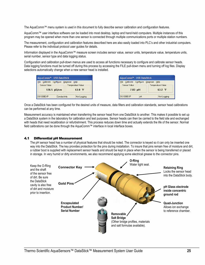
The AquaComm™ menu system is used in this document to fully describe sensor calibration and configuration features.
AquaComm™ user interface software can be loaded into most desktop, laptop and hand-held computers. Multiple instances of this program may be opened when more than one sensor is connected through multiple communications ports or multiple station numbers.
The measurement, configuration and calibration features described here are also easily loaded into PLC’s and other industrial computers. Please refer to the individual protocol user guides for details.
Information displayed in the AquaComm™ measure screen includes sensor value, sensor units, temperature value, temperature units, serial number, sensor type and data logging status.
Configuration and calibration pull-down menus are used to access all functions necessary to configure and calibrate sensor heads. Data logging functions must be turned off during this process by accessing the FILE pull-down menu and turning off log files. Display selections automatically change when a new sensor head is installed.
Once a DataStick has been configured for the desired units of measure, data filters and calibration standards, sensor head calibrations can be performed at any time.
Measurement accuracy is maintained when transferring the sensor head from one DataStick to another. This makes it possible to set up a DataStick system in the laboratory for calibration and test purposes. Sensor heads can then be carried to the field site and exchanged with heads that need recalibration or refurbishment. This process reduces down time and actually extends the life of the sensor. Normal field calibrations can be done through the AquaComm™ interface in local interface boxes.
4.1 Differential pH Measurement The pH sensor head has a number of physical features that should be noted. The connector is keyed so it can only be inserted one way into the DataStick. The key provides protection for the pins during installation. To insure that pins remain free of moisture and dirt, a rubber boot is supplied with replacement sensor heads and should be kept in place when the sensor is being transferred or placed in storage. In very humid or dirty environments, we also recommend applying some electrical grease to the connector pins.
Keep the O-Ring and the shaft of the sensor free of dirt. Be sure the DataStick cavity is also free of dirt and moisture prior to insertion.
Connector Key
O-Ring Water tight seal.
Retaining Ring Locks the sensor head into the DataStick body.
Encapsulated Product Number/ Serial Number
pH Glass electrode inside concentric ground rod
Quad-Junction Allows ion exchange to reference chamber.
Removable Salt Bridge (Other bridge profiles, materials and salt formulas available).
Gold Pins

Thermo Scientific AquaSensors™ DataStick™ Measurement System User Guide 26
4.1.1 pH Interface Overview When a pH sensor head is installed in the DataStick, AquaComm™ will automatically display pH, temperature, sensor type and DataStick serial number. Pull-down menus will also automatically provide calibration, configuration and diagnostic choices for pH.
Factory default configurations for a pH sensor head are:
• Units of measure: pH (options include mV)
• Units for temperature: °C (options include °F)
• Sensor Filter: 1 Second (options include 0 to 100 seconds in 1 second increments)
• Temperature Filter: 1 Second (options include 0 to 100 seconds in 1 second increments)
• Buffer Standards: 4 pH, 7pH, and 10pH (options include DIN 19267: 1.09pH, 4.65pH, 6.79pH, 9.23pH and 12.75pH) When configuration information is changed in a DataStick, the information remains with the DataStick. If a new sensor head is installed, the configuration will remain as programmed by the user. It will not revert to default values. When calibrating the pH measurement, be sure that the current configuration settings are well understood.
Calibration options for the differential pH sensor are:
• 2-point Buffer Calibration: Sensor placed in two buffer standards and automatically adjusts offset and span.
• 1-point Buffer Calibration: Sensor placed in one buffer standard and automatically adjusts measurement offset.
• 2-point Sample Calibration: Desired reading entered for two samples at least 3 pH units apart; adjusts offset and span.
• 1-point Sample Calibration: Desired reading is entered for one sample to adjust measurement offset.
Calibration options for temperature are:
• 1-point Sample Calibration: Desired reading is entered for one sample to adjust measurement offset.
4.1.2 pH Configuration The AquaComm™ CONFIGURE functions can be accessed from a pull-down menu that automatically changes based on the sensor type connected to the DataStick. When a pH sensor is connected, settings for data filters, units of measure and buffer standards can be viewed or changed.

Thermo Scientific AquaSensors™ DataStick™ Measurement System User Guide 27
4 . 1 . 2 . 1 C O N F I G U R A T I O N O F B U F F E R S T A N D A R D S
Select BUFFER STANDARD from the Configuration pull-down menu to view or change the buffer standard that will be used as a reference for buffer calibrations.
There are two pre-defined standards currently used with the DataStick system. The Thermo Scientific AquaSensors buffer standard is the default when the system is reset.
Thermo Scientific AquaSensors Buffer Standards: 4 pH, 7 pH and 10 pH. (DEFAULT).
DIN 19267 Buffer Standards: 1.09 pH, 4.65 pH, 6.79 pH, 9.23 pH and 12.75 pH.
When using a buffer standard that is not included in the pre-defined buffer standard, use the ‘2-point sample’ calibration method.
ASCII Command to View Buffer Settings
Function Command Response Explanation Get Standards GPHBUF 0 4/7/10 pH Standards 1 DIN pH Standards
ASCII Commands to Set Buffer Settings
Function Command Explanation Set Standard to 4/7/10s SPHBUF 0 Sets buffer calibration based on 4, 7 and 10 pH standards Set Standard to DIN SPHBUF 1 Sets buffer calibration based on DIN Standards
All Set Commands will respond with “OK” if accepted and “ERROR” if not accepted
4 . 1 . 2 . 2 S E N S O R F I L T E R
Select SENSOR FILTER from the Configuration pull-down menu to view or change the sensor filter constant.
The filter setting can be changed by selecting the edit box and typing in the desired constant. To accept the change, click OK. To abort the change, click CANCEL.
If the sensor filter is set to 5 seconds, it will take 5 seconds to reach 90% of the final value when the reading changes. Measurements are averaged to reduce periodic variations.
The default filter setting is 1 second and the maximum filter is 100 seconds. Use zero seconds for a completely unfiltered reading.

Thermo Scientific AquaSensors™ DataStick™ Measurement System User Guide 28
4 . 1 . 2 . 3 T E M P E R A T U R E F I L T E R
Select TEMPERATURE FILTER from the Configuration pull-down menu to view or change the temperature filter constant.
The filter setting can be changed by selecting the edit box and typing in the desired constant. To accept the change, click OK. To abort the change, click CANCEL.
If the temperature filter is set to 5 seconds, it will take 5 seconds to reach 90% of the final value when the reading changes. Measurements are averaged to reduce periodic variations.
The default filter setting is 1 second and the maximum filter is 100 seconds. Use zero seconds for a completely unfiltered reading.
ASCII Commands to View Sensor and Temperature Filter Settings Function Command Response Explanation Get Sensor Filter GSFIL A number between 0 and 100. Number of seconds. Get Temp Filter GTFIL A number between 0 and 100. Number of seconds.
ASCII Commands to Set Sensor and Temperature Filter Settings
Function Command Explanation Set Sensor Filter SSFIL X Where X is a number between 0 and 100. Units are in seconds. Set Temp Filter STFIL X Where X is a number between 0 and 100. Units are in seconds.
All Set Commands will respond with “OK” if accepted and “ERROR” if not accepted
4 . 1 . 2 . 4 S E N S O R U N I T S
Select SENSOR UNITS from the Configuration pull-down menu to view or change units of measure.
Units shown in the sensor units window are active. To change units or to review options, scroll the selection list. Click on the desired units of measure to place the new choice in the sensor units window. To accept the change, click OK. To abort the change, click CANCEL.
For pH sensors, the units of measure can be set to pH or millivolts. The default units are pH.
Although temperature and sensor filter constants are independently controlled the best results are generally achieved when both filters are set to the same constant.

Thermo Scientific AquaSensors™ DataStick™ Measurement System User Guide 29
ASCII Commands to View Sensor units Function Command Response Explanation View Sensor Units GSUNITS 0 Data reported in pH units 1 Data reported in mV units
ASCII Commands to Set Sensor units
Function Command Explanation Set to pH SSUNITS 0 Sensor data will be reported in pH units Set to mV SSUNITS 1 Sensor data will be reported in mV units
All Set Commands will respond with “OK” if accepted and “ERROR” if not accepted
4 . 1 . 2 . 5 T E M P E R A T U R E U N I T S
Select TEMPERATURE UNITS from the Configuration pull-down menu to view or change units of measure.
Units shown in the temperature units window are active. To change units or to review options, scroll the selection list. Click on the desired units of measure to place the new choice in the sensor units window. To accept the change, click OK. To abort the change, click CANCEL.
Temperature can be displayed in °C or °F. Default units are °C.
ASCII Commands to View Temperature units
Command Response Explanation GTUNITS 0 Data reported in °C 1 Data reported in °F
ASCII Commands to Set Temperature units
Command Explanation STUNITS 0 Sensor data will be reported in °C STUNITS 1 Sensor data will be reported in °F
All Set Commands will respond with “OK” if accepted and “ERROR” if not accepted

Thermo Scientific AquaSensors™ DataStick™ Measurement System User Guide 30
4.1.3 pH Calibration When a pH sensor is connected to the DataStick, calibration choices specific to pH are automatically available. After a calibration, the sensor-head can be moved to another DataStick and measurement accuracy will be maintained. For the most accurate measurements a 2-point buffer calibration should be performed.
Sensors are calibrated at the factory. When field calibrations are necessary, 1-point buffer, 2-point buffer, 1-point sample and 2-point sample calibrations are available.
4 . 1 . 3 . 1 1 - P O I N T B U F F E R M E T H O D
Select 1-POINT BUFFER from the calibration menu to begin a calibration in a known buffer standard.
In a buffer calibration, the DataStick assumes that the sensor has been placed in a pre-defined buffer standard and automatically equates the current reading to the closest standard value. For a 1-point pH buffer calibration, instructions are shown in the status box on the left side of the calibration screen. The sensor and temperature values are shown on the right side of the screen.
Place the pH DataStick sensor into the buffer solution. Wait for the sensor and temperature readings to stabilize. Press the CALIBRATE button and the sensor will begin the process of changing the current pH reading to the closest buffer standard reading as defined by the buffer standard selected.
Once the calibration has been initiated it will take between 30 seconds and 2 minutes depending on sensor and temperature measurement stability. During this period, the abort sequence can be initiated as shown with the active Abort button.

Thermo Scientific AquaSensors™ DataStick™ Measurement System User Guide 31
When the calibration is complete, the abort option is no longer available.
When the point has been successfully calibrated, measured values will be based on the new calibration. The rate of change in reading from the old measured value to the new will be dependent on the sensor filter value that is entered in the configuration menu.
Exiting the calibration menu will return the user to the measure screen.
ASCII Command to Initiate a pH 1-Point Buffer Calibration
Function Command Explanation
1-Point Buffer CALS1PB Initiates a 1-point calibration for pH sensors
All Calibration Commands will respond with “OK” if accepted and “ERROR” if not accepted
The status of the calibration can be reviewed with the CALSTATUS command. When the last number returned is a 1, the calibration is in process. When the last number returned is a 2, the calibration has been successful. Any other number indicates a specific failure mode (see appendix).
4 . 1 . 3 . 2 2 - P O I N T B U F F E R M E T H O D
Select 2-POINT BUFFER from the calibration menu to begin a pH calibration sequence.
A 2-point buffer calibration is the recommended calibration method for most accurate results and requires 2 buffer standards at least 3 pH units apart. Every pH sensor is calibrated this way when it leaves the factory and will maintain accuracy for a period of time when the sensor head is kept wet.
Either Thermo Scientific AquaSensors pH standards or DIN pH standards can be selected from the configuration menu for this calibration method. This process allows calibration to be done without entering any numbers but requires that the buffer standards used for the calibration match the standard family that is selected in the configuration menu. The default standards are 4 pH, 7 pH and 10 pH.

Thermo Scientific AquaSensors™ DataStick™ Measurement System User Guide 32
The first buffer should generally be a 7 pH standard to set the measurement offset.
After selecting the 2-point pH buffer calibration method, the sensor should be placed in the first standard and when sensor and temperature readings are stable, click the CALIBRATE button to initiate the calibration or click EXIT to return to the main measure screen.
Once the calibration has been initiated it will take between 15 seconds and 2 minutes depending on sensor and temperature measurement stability. During this period, the abort sequence can be initiated as shown with the active Abort button.
Once the 2-point buffer calibration has successfully completed storage of the first point, the status box will prompt the user to place the sensor in the second solution before initiating calibration of the second point. Please note that the reading will not be adjusted after the first calibration point. Calibration changes will only take effect after both calibration points have been accepted.

Thermo Scientific AquaSensors™ DataStick™ Measurement System User Guide 33
Once the sensor has been placed in the second buffer standard and sensor and temperature readings have stabilized, click the CALIBRATE button to initiate the calibration of the second buffer standard.
While the calibration is in progress the operation can be aborted at any time. The abort will take the system back to normal measurements using the previous calibration values.
Once the calibration for both points is successful, the displayed sensor value will be based on the new calibration.
Exiting the calibration function will return the display to the measure screen. In this case the measured value of 4.01 pH confirms that the sensor calibration in 4.01 pH buffer solution was successful.
Thermo Scientific AquaSensors™ DataStick™ Measurement System User Guide 34
ASCII Command to initiate a 2-Point Buffer Calibration
Function Command Explanation
2-Point Buffer CALPH2PB 0 Initiates 1st point of a 2-point buffer calibration
CALPH2PB 1 Initiates 2nd point of a 2-point buffer calibration
All Calibration Commands will respond with “OK” if accepted and “ERROR” if not accepted
The status of the calibration can be reviewed with the CALSTATUS command. When the last number returned is a 1, the calibration is in process. When the last number returned is a 2, the calibration has been successful. Any other number indicates a specific failure mode (see appendix).
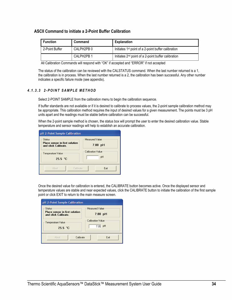
4 . 1 . 3 . 3 2 - P O I N T S A M P L E M E T H O D
Select 2-POINT SAMPLE from the calibration menu to begin the calibration sequence.
If buffer standards are not available or if it is desired to calibrate to process values, the 2-point sample calibration method may be appropriate. This calibration method requires the input of desired values for a given measurement. The points must be 3 pH units apart and the readings must be stable before calibration can be successful.
When the 2-point sample method is chosen, the status box will prompt the user to enter the desired calibration value. Stable temperature and sensor readings will help to establish an accurate calibration.
Once the desired value for calibration is entered, the CALIBRATE button becomes active. Once the displayed sensor and temperature values are stable and near expected values, click the CALIBRATE button to initiate the calibration of the first sample point or click EXIT to return to the main measure screen.

Thermo Scientific AquaSensors™ DataStick™ Measurement System User Guide 35
Once the calibration has been initiated it will take somewhere between 30 seconds and 2 minutes depending on sensor and temperature measurement stability. During this period, the abort sequence can be initiated as shown with the active ABORT button.
When the first calibration point is accepted, the status box will prompt the user to place the sensor in the second solution of known value.
Wait until the sensor and temperature values are stable in the second solution.
Enter the desired value and initiate calibration by clicking the CALIBRATE button.

Thermo Scientific AquaSensors™ DataStick™ Measurement System User Guide 36
Once the calibration has been initiated it will take somewhere between 30 seconds and 2 minutes depending on sensor and temperature measurement stability. During this period, the abort sequence can be initiated as shown with the active ABORT button.
When the second point has been successfully calibrated, measured values will be based on the new calibration. The rate of change in reading from the old measured value to the new will be dependent on the sensor filter value that is entered in the configuration menu.
Exiting the calibration menu will return the display to the measure screen.
ASCII Command to initiate a 2-Point Sample Calibration
Function Command Explanation
2-Point Sample First Sample CALPH2PS 0 X Initiates 1st point of a 2-point sample calibration;
Where X is the desired pH value.
2-Point Sample Second Sample CALPH2PS 1 Y Initiates 2nd point of a 2-point buffer calibration;
Where Y is the desired pH value.
All Calibration Commands will respond with “OK” if accepted and “ERROR” if not accepted
The status of the calibration can be reviewed with the CALSTATUS command. When the last number returned is a 1, the calibration is in process. When the last number returned is a 2, the calibration has been successful. Any other number indicates a specific failure mode (see appendix).

Thermo Scientific AquaSensors™ DataStick™ Measurement System User Guide 37
4 . 1 . 3 . 4 1 - P O I N T S A M P L E M E T H O D
Select 1-POINT SAMPLE from the calibration menu to begin a calibration.
When the 1-point sample method is chosen, the status box will prompt the user to enter the desired calibration value.
Stable temperature and sensor readings will also help to establish an accurate calibration.
Once the desired value for calibration is entered, the CALIBRATE button becomes active. Once the displayed sensor and temperature values are stable and near expected values, click the CALIBRATE button to initiate the calibration or click EXIT to return to the main measure screen.
Once the calibration has been initiated it will take somewhere between 30 seconds and 2 minutes depending on sensor and temperature measurement stability. During this period, the abort sequence can be initiated as shown with the active ABORT button.

Thermo Scientific AquaSensors™ DataStick™ Measurement System User Guide 38
When the point has been successfully calibrated, measured values will be based on the new calibration. The rate of change in reading from the old measured value to the new will be dependent on the sensor filter value that is entered in the configuration menu.
Exiting the calibration menu will return the display to the measure screen.
ASCII Command to initiate a 1-Point Sample pH Calibration
Function Command Explanation
1-Point Sample CALS1PS Initiates a 1-point calibration of the pH sensor
All Calibration Commands will respond with “OK” if accepted and “ERROR” if not accepted
The status of the calibration can be reviewed with the CALSTATUS command. When the last number returned is a 1, the calibration is in process. When the last number returned is a 2, the calibration has been successful. Any other number indicates a specific failure mode (see appendix).
4.1.4 pH Sensor Diagnosis
ASCII Command to View pH Sensor Slope Function Command Response Explanation
Get Sensor Slope GSSLOPE A number between 0 and –100
The pH sensor slope based on the most-recent calibration in mV/pH
This command is available in DataStick firmware D3.22 or later. The DataStick firmware version can be obtained using the GCVSN command.

Thermo Scientific AquaSensors™ DataStick™ Measurement System User Guide 39
4.1.5 pH Sensor Maintenance In order to maintain accurate measurement values, the sensor will need occasional maintenance. The harsher the process, the more maintenance the sensor will require. Proper and regular maintenance will yield a longer sensor life.
The recommended pH sensor cleaning procedure is as follows:
1. Remove sensor from service and rinse or spray it with warm water to remove heavy deposits.
2. Soak the sensor in a container of hot detergent water for 30 minutes. Do not use detergents that contain oily skin softeners like aloe or lanolin that can coat the glass electrode. Powdered Alconox™ and Dawn™ dishwashing liquid work well.
3. Use a soft-bristled brush, such as a soft toothbrush, and hot detergent water to scrub the entire electrode end of the sensor, being careful not to scratch or break the glass electrode.
4. Rinse the electrode end with clean warm water.
5. If deposits are still present on glass electrode repeat steps 2 and 3. In the case of lime or other mineral deposits a weak solution (about 0.1 M) of hydrochloric acid may be used. In some cases, a dilute solution (about 10:1) of water and chlorine bleach or a solution of water and EDTA may also work. Stubborn oil or grease deposits may require cleaning with a solvent such as acetone or alcohol. Assure that the sensor body in compatible with the solvent. Protein deposits may be cleaned with a pepsin-based cleaning solution. Bacterial or mold growths may be removed with dilute chlorine bleach.
Note: Cleaning can be process-specific. Some users will have to develop a procedure that works best for them.
Caution: Ensure that a dangerous chemical reaction will not occur between process deposits and the cleaning solution, such as compounds of cyanide, and the hydrochloric acid. Cyanide is often used in electroplating and in gold refining. If in doubt check with a chemist.
Caution: When using dangerous chemicals such as hydrochloric acid or chlorine bleach, use all appropriate safety precautions, especially eye protection.
Before returning the sensor to service, allow it to soak in water or buffer at ambient temperature for about an hour to stabilize. After cleaning the sensor, always calibrate the sensor head before installing in the process.
Thermo Scientific AquaSensors™ DataStick™ Measurement System User Guide 40
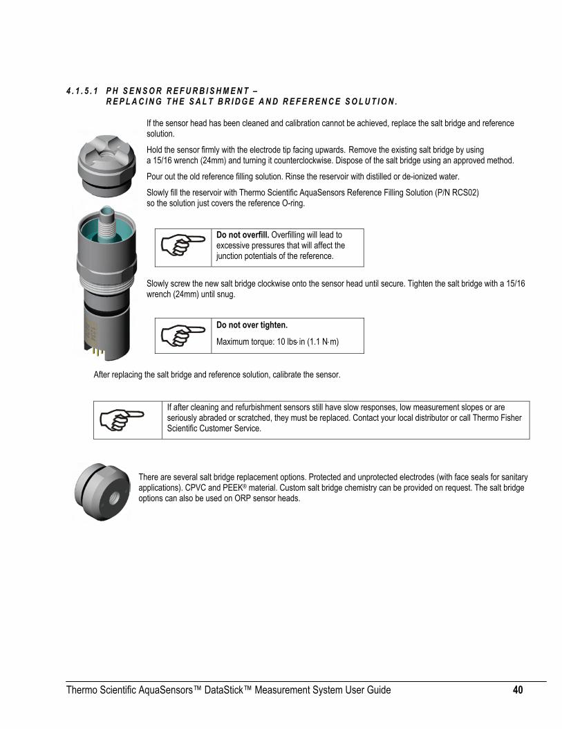
4 . 1 . 5 . 1 P H S E N S O R R E F U R B I S H M E N T – R E P L A C I N G T H E S A L T B R I D G E A N D R E F E R E N C E S O L U T I O N .
If the sensor head has been cleaned and calibration cannot be achieved, replace the salt bridge and reference solution.
Hold the sensor firmly with the electrode tip facing upwards. Remove the existing salt bridge by using a 15/16 wrench (24mm) and turning it counterclockwise. Dispose of the salt bridge using an approved method.
Pour out the old reference filling solution. Rinse the reservoir with distilled or de-ionized water.
Slowly fill the reservoir with Thermo Scientific AquaSensors Reference Filling Solution (P/N RCS02) so the solution just covers the reference O-ring.
Slowly screw the new salt bridge clockwise onto the sensor head until secure. Tighten the salt bridge with a 15/16 wrench (24mm) until snug.
After replacing the salt bridge and reference solution, calibrate the sensor.
If after cleaning and refurbishment sensors still have slow responses, low measurement slopes or are seriously abraded or scratched, they must be replaced. Contact your local distributor or call Thermo Fisher Scientific Customer Service.
There are several salt bridge replacement options. Protected and unprotected electrodes (with face seals for sanitary applications). CPVC and PEEK® material. Custom salt bridge chemistry can be provided on request. The salt bridge options can also be used on ORP sensor heads.
Do not overfill. Overfilling will lead to excessive pressures that will affect the junction potentials of the reference.
Do not over tighten.
Maximum torque: 10 lbs⋅in (1.1 N⋅m)

Thermo Scientific AquaSensors™ DataStick™ Measurement System User Guide 41
4 . 1 . 5 . 2 P H S P A R E P A R T S
Description
Part Number
Reference Cell Filling Solution (500 ml) RCS02
Protected PEEK® Salt Bridge (O-ring included) SBS01
Flat PEEK® Salt Bridge (O-ring included) SBS02
Protected CPVC Salt Bridge (O-ring included) SBS03
Flat CPVC Salt Bridge (O-ring included) SBS04
pH Sensor Storage Solution SBS09 Protective Cap SBC01

Thermo Scientific AquaSensors™ DataStick™ Measurement System User Guide 42
4.2 Differential ORP Measurement The ORP sensor head has a number of physical features that should be noted. The connector is keyed so it can only be inserted one way into the DataStick. The key provides protection for the pins during installation. To insure that pins remain free of moisture and dirt, a rubber boot is supplied with replacement sensor heads and should be kept in place when transferred or placed in storage. In very humid or dirty environments, we also recommend applying some electrical grease to the connector pins.
Keep the O-Ring and the shaft of the sensor free of dirt. Be sure the DataStick cavity is also free of dirt and moisture prior to insertion.
4.2.1 ORP Interface Overview When an ORP sensor head is installed in the DataStick, AquaComm™ will automatically display millivolts, temperature, sensor type and DataStick serial number. Pull-down menus will also automatically provide calibration, configuration and diagnostic choices for ORP.
Factory default configurations for an ORP sensor head are:
• Units of measure: millivolts (mV)
• Units for temperature: °C (options include °F)
• Sensor Filter: 1 Second (options include 0 to 100 seconds in 1 second increments)
• Temperature Filter: 1 Second (options include 0 to 100 seconds in 1 second increments)
Connector Key Retaining Ring Locks the sensor head into the DataStick body
Encapsulated Product Number/ Serial Number
Platinum electrode inside concentric stainless steel ground rod
Quad-Junction Allows ion exchange to reference chamber
Removable Salt Bridge (Other bridge profiles, materials and salt formulas available).
Gold Pins
O-Ring Water tight seal

Thermo Scientific AquaSensors™ DataStick™ Measurement System User Guide 43
When configuration information is changed in a DataStick, the information remains with the DataStick. If a new sensor head is installed, the configuration will remain as programmed by the user. It will not revert to default values.
Calibration options for the differential ORP sensor are:
• 1-point Sample Calibration: Desired reading is entered for one sample to adjust measurement offset.
Calibration options for temperature are:
• 1-point Sample Calibration: Desired reading is entered for one sample to adjust measurement offset.
4.2.2 ORP Configuration The AquaComm™ CONFIGURE functions can be accessed from a pull-down menu that automatically changes based on the sensor type connected to the DataStick. When an ORP sensor is connected, settings for data filters and units of measure can be viewed or changed.
4 . 2 . 2 . 1 S E N S O R F I L T E R S
Select SENSOR FILTER from the Configuration pull-down menu to view or change the sensor filter constant.
The filter setting can be changed by selecting the edit box and typing in the desired constant. To accept the change, click OK. To abort the change, click CANCEL.
If the sensor filter is set to 5 seconds, it will take 5 seconds to reach 90% of the final value when the reading changes. Measurements are averaged to reduce periodic variations.
The default filter setting is 1 second and the maximum filter is 100 seconds. Use zero seconds for a completely unfiltered reading.

Thermo Scientific AquaSensors™ DataStick™ Measurement System User Guide 44
4 . 2 . 2 . 2 T E M P E R A T U R E F I L T E R
Select TEMPERATURE FILTER from the Configuration pull-down menu to view or change the temperature filter constant.
The filter setting can be changed by selecting the edit box and typing in the desired constant. To accept the change, click OK. To abort the change, click CANCEL.
If the temperature filter is set to 5 seconds, it will take 5 seconds to reach 90% of the final value when the reading changes. Measurements are averaged to reduce periodic variations.
The default filter setting is 1 second and the maximum filter is 100 seconds. Use zero seconds for a completely unfiltered reading.
ASCII Commands to View Sensor and Temperature Filter Settings
Function Command Response Explanation
Get Sensor Filter GSFIL A number between 0 and 100. Number of seconds.
Get Temp Filter GTFIL A number between 0 and 100. Number of seconds.
ASCII Commands to Set Sensor and Temperature Filter Settings
Function Command Explanation
Set Sensor Filter SSFIL X Where X is a number between 0 and 100. Units are in seconds.
Set Temp Filter STFIL X Where X is a number between 0 and 100. Units are in seconds.
All Set Commands will respond with “OK” if accepted and “ERROR” if not accepted.
4 . 2 . 2 . 3 S E N S O R U N I T S
The SENSOR UNITS selection is not available for ORP measurements. Units of measure are in millivolts (mV).
4 . 2 . 2 . 4 T E M P E R A T U R E U N I T S
Select TEMPERATURE UNITS from the Configuration pull-down menu to view or change units of measure.
ORP and temperature measurements are completely independent of one another and filter constants can also be independent.
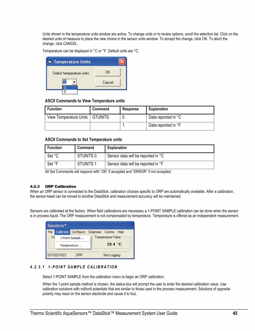
Thermo Scientific AquaSensors™ DataStick™ Measurement System User Guide 45
Units shown in the temperature units window are active. To change units or to review options, scroll the selection list. Click on the desired units of measure to place the new choice in the sensor units window. To accept the change, click OK. To abort the change, click CANCEL.
Temperature can be displayed in °C or °F. Default units are °C.
ASCII Commands to View Temperature units
Function Command Response Explanation
View Temperature Units GTUNITS 0 Data reported in °C 1 Data reported in °F
ASCII Commands to Set Temperature units
Function Command Explanation
Set °C STUNITS 0 Sensor data will be reported in °C Set °F STUNITS 1 Sensor data will be reported in °F
All Set Commands will respond with “OK” if accepted and “ERROR” if not accepted.
4.2.3 ORP Calibration When an ORP sensor is connected to the DataStick, calibration choices specific to ORP are automatically available. After a calibration, the sensor-head can be moved to another DataStick and measurement accuracy will be maintained.
Sensors are calibrated at the factory. When field calibrations are necessary a 1-POINT SAMPLE calibration can be done when the sensor is in process liquid. The ORP measurement is not compensated by temperature. Temperature is offered as an independent measurement.
4 . 2 . 3 . 1 1 - P O I N T S A M P L E C A L I B R A T I O N
Select 1-POINT SAMPLE from the calibration menu to begin an ORP calibration.
When the 1-point sample method is chosen, the status box will prompt the user to enter the desired calibration value. Use calibration solutions with millivolt potentials that are similar to those used in the process measurement. Solutions of opposite polarity may react on the sensor electrode and cause it to foul.

Thermo Scientific AquaSensors™ DataStick™ Measurement System User Guide 46
For best calibration results, do not calibrate in both negative and positive millivolt solutions. Even after thorough rinsing, positive and negative ORP solutions can react and foul the ORP salt bridge.
Once the desired value for calibration is entered, the CALIBRATE button becomes active. Once the displayed sensor value is stable and near the expected value, click the CALIBRATE button to initiate the calibration or click EXIT to return to the main measure screen.
Once the calibration has been initiated it will take somewhere between 30 seconds and 2 minutes depending on sensor measurement stability. During this period, the abort sequence can be initiated as shown with the active ABORT button.

Thermo Scientific AquaSensors™ DataStick™ Measurement System User Guide 47
When the point has been successfully calibrated, measured values will be based on the new calibration. The rate of change in reading from the old measured value to the new will be dependent on the sensor filter value that is entered in the configuration menu.
Exiting the calibration menu will return the user to the measure screen.
ASCII Command to initiate a 1-Point Sample Calibration
Function Command Explanation
1-Point Sample CALS1PS Initiates a 1-point calibration
All Calibration Commands will respond with “OK” if accepted and “ERROR” if not accepted
The status of the calibration can be reviewed with the CALSTATUS command. When the last number returned is a 1, the calibration is in process. When the last number returned is a 2, the calibration has been successful. Any other number indicates a specific failure mode (see appendix).
4.2.4 ORP Sensor Maintenance In order to maintain accurate measurement values, the sensor will need occasional maintenance. The harsher the process, the more maintenance the sensor will require. Proper and regular maintenance will yield a longer sensor life.
The recommended ORP sensor cleaning procedure is as follows:
1. Remove sensor from service and rinse or spray it with warm water to remove heavy deposits. 2. Soak the sensor in a container of hot detergent water for 30 minutes. Do not use detergents that contain oily skin softeners
like aloe or lanolin that can coat the glass electrode. Powdered Alconox™ and Dawn™ dishwashing liquid work well. 3. Use a soft-bristled brush, such as a soft toothbrush, and hot detergent water to scrub the entire electrode end of the sensor,
being careful not to scratch or break the glass electrode. 4. Rinse the electrode end with clean warm water. 5. If deposits are still present on glass electrode repeat steps 2 and 3. In the case of lime or other mineral deposits a weak
solution (about 0.1 M) of hydrochloric acid may be used. In some cases, a dilute solution (about 10:1) of water and chlorine bleach or a solution of water and EDTA may also work. Stubborn oil or grease deposits may require cleaning with a solvent such as acetone or alcohol. Assure that the sensor body in compatible with the solvent. Protein deposits may be cleaned with a pepsin-based cleaning solution. Bacterial or mold growths may be removed with dilute chlorine bleach.

Thermo Scientific AquaSensors™ DataStick™ Measurement System User Guide 48
Caution: When using dangerous chemicals such as hydrochloric acid or chlorine bleach, use all appropriate safety precautions, especially eye protection.
Before returning the sensor to service, allow it to soak in water or buffer at ambient temperature for about an hour to stabilize. After cleaning the sensor, always calibrate the sensor head before installing in the process. 4 . 2 . 4 . 1 O R P S E N S O R R E F U R B I S H M E N T –
R E P L A C I N G T H E S A L T B R I D G E A N D R E F E R E N C E S O L U T I O N .
If the sensor head has been cleaned and calibration cannot be achieved, replace the salt bridge and reference solution.
Hold the sensor firmly with the electrode tip facing upwards. Remove the existing salt bridge by using a 15/16 wrench (24mm) and turning it counterclockwise. Dispose of the salt bridge using an approved method.
Pour out the old reference filling solution. Rinse the reservoir with distilled or de-ionized water.
Slowly fill the reservoir with Thermo Scientific AquaSensors Reference Filling Solution (P/N RCS02) so the solution just covers the reference O-ring.
Slowly screw the new salt bridge clockwise onto the sensor head until secure. Tighten the salt bridge with a 15/16 wrench (24mm) until snug.
After replacing the salt bridge and reference solution, calibrate the sensor.
If after cleaning and refurbishment sensors still have slow responses, low measurement slopes or are seriously abraded or scratched, they must be replaced. Contact your local distributor or call Thermo Fisher Scientific Customer Service.
There are several salt bridge replacement options. Protected and unprotected electrodes (with face seals for sanitary applications). CPVC and PEEK® material. Custom salt bridge chemistry can be provided on request. The salt bridge options can also be used with pH sensor heads.
Do not overfill. Overfilling will lead to excessive pressures that will affect the junction potentials of the reference.
Do not over tighten.
Maximum torque: 10 lbs⋅in (1.1 N⋅m)

Thermo Scientific AquaSensors™ DataStick™ Measurement System User Guide 49
Connector Key
Encapsulated Product Number/ Serial Number
Gold Pins Retaining Ring Locks the sensor head
4.2.5 ORP Spare Parts
Description
Part Number
Reference Cell Filling Solution (500 ml) RCS02 Protected PEEK® Salt Bridge (O-ring included)
SBS01
Flat PEEK® Salt Bridge (O-ring included)
SBS02
Protected CPVC Salt Bridge (O-ring included)
SBS03
Flat CPVC Salt Bridge (O-ring included)
SBS04
ORP Sensor Storage Solution SCS04 Protective Cap SBC01
4.3 Two Electrode Conductivity and Resistivity The two electrode contacting conductivity sensor head series has a number of physical features that should be noted. The connector is keyed. The key provides protection for the pins during installation. To insure that pins remain free of moisture and dirt, a rubber boot is supplied with replacement sensor heads and should be kept in place when the sensor is being transferred or placed in storage. In very humid or dirty environments, we also recommend applying some electrical grease to the connector pins.
Keep the O-Ring and the shaft of the sensor free of dirt. Be sure the DataStick cavity is also free of dirt and moisture prior to insertion.
4.3.1 Contacting Conductivity/Resistivity Overview When a contacting conductivity sensor head is installed in the DataStick, AquaComm™ will automatically display conductivity or resistively, temperature, sensor type and DataStick serial number. Pull-down menus will also automatically provide calibration, configuration and diagnostic choices for conductivity.
O-Ring Water tight seal
Resistivity (Cell K = 0.1) Conductivity (Cell K = 1.0)
Resistivity (Cell K = 0.1) Conductivity (Cell K = 1.0)

Thermo Scientific AquaSensors™ DataStick™ Measurement System User Guide 50
Factory default configurations for contacting conductivity / resistivity sensor heads are:
• Units of measure: µS/cm (options include %, ppm and MΩ·cm)
• Units for temperature: °C (options include °F)
• Sensor Filter: 1 Second (options include 0 to 100 seconds in 1 second increments)
• Temperature Filter: 1 Second (options include 0 to 100 seconds in 1 second increments)
• Cell Constant: 1.0 for Conductivity electrodes, 0.1 for Resistivity electrodes
• Reference Temperature: 25°C (options include 0°C to 100°C)
• Compensation Slope: 2% / °C (options include 0 to 9.9 %/°C)
• Concentration Table (10 Points Capability): Point 1 is (0 µS/cm, 0%), Point 2 is (20,000µS/cm, 99.99%) When configuration information is changed in a DataStick, the information remains with the DataStick. If a new sensor head is installed, the configuration will remain as programmed by the user. It will not revert to default values.
Calibration options for the toroidal conductivity sensor are:
• 1-point Sample Calibration: Desired reading is entered for one sample to adjust measurement offset.
• Zero: Sets the zero point for the sensor in dry air. Be sure the sensor is clean and dry.
Calibration options for temperature are:
• 1-point Sample Calibration: Desired reading is entered for one sample to adjust measurement offset.
4.3.2 Configuration of Contacting Conductivity Sensors
The AquaComm™ CONFIGURE functions can be accessed from a pull-down menu that automatically changes based on the sensor type connected to the DataStick. When a conductivity sensor is connected, settings for data filters, units of measure, reference temperature, temperature compensation and concentration tables can be viewed or changed. It is also possible to manually adjust the cell constant of the connected sensor if a user guide adjustment of the measure value is desired. It is best to view the adjusted cell constant after performing a 1-point sample calibration.

Thermo Scientific AquaSensors™ DataStick™ Measurement System User Guide 51
4 . 3 . 2 . 1 S E N S O R F I L T E R
Select SENSOR FILTER from the Configuration pull-down menu to view or change the sensor filter constant.
The filter setting can be changed by selecting the edit box and typing in the desired constant. To accept the change, click OK. To abort the change, click CANCEL.
If the sensor filter is set to 5 seconds, it will take 5 seconds to reach 90% of the final value when the reading changes. Measurements are averaged to reduce periodic variations.
The default filter setting is 1 second and the maximum filter is 100 seconds. Use zero seconds for a completely unfiltered reading.
4 . 3 . 2 . 2 T E M P E R A T U R E F I L T E R
Select TEMPERATURE FILTER from the Configuration pull-down menu to view or change the temperature filter constant.
The filter setting can be changed by selecting the edit box and typing in the desired constant. To accept the change, click OK. To abort the change, click CANCEL.
If the temperature filter is set to 5 seconds, it will take 5 seconds to reach 90% of the final value when the reading changes. Measurements are averaged to reduce periodic variations.
The default filter setting is 1 second and the maximum filter is 100 seconds. Use zero seconds for a completely unfiltered reading.
ASCII Commands to View Sensor and Temperature Filter Settings
Function Command Response Explanation
Get Sensor Filter GSFIL A number between 0 and 100. Number of seconds.
Get Temp Filter GTFIL A number between 0 and 100. Number of seconds.
Although temperature and sensor filter constants are independently controlled the best results are generally achieved when both filters are set to the same constant.

Thermo Scientific AquaSensors™ DataStick™ Measurement System User Guide 52
ASCII Commands to Set Sensor and Temperature Filter Settings Function Command Explanation
Set Sensor Filter SSFIL X Where X is a number between 0 and 100. Units are in seconds.
Set Temp Filter STFIL X Where X is a number between 0 and 100. Units are in seconds.
4 . 3 . 2 . 3 S E N S O R U N I T S
Select SENSOR UNITS from the Configuration pull-down menu to view or change units of measure.
Units shown in the sensor units window are active. To change units or to review options, scroll the selection list. Click on the desired units of measure to place the new choice in the sensor units window. To accept the change, click OK. To abort the change, click CANCEL.
For contacting conductivity sensors, conductivity measurements can be set to conductivity in µS/cm, concentration in %, total dissolved solids in ppm and resistivity in MΩ•cm.
Default units of measure are µS/cm.
Concentration measurements are converted from the data points entered in a 10-point concentration table that can be viewed and edited from the Configuration pull-down menu.
ASCII Commands to View Sensor units
Function Command Response Explanation
View Sensor Units GSUNITS 0 Data reported in µS/cm units
1 Data reported in % concentration
2 Data reported in ppm (total dissolved solids)
3 Data reported in MΩ·cm units
ASCII Commands to Set Sensor units Function Command Explanation
Set to µS/cm SSUNITS 0 Sensor data will be reported in µS/cm units
Set to % SSUNITS 1 Sensor data will be reported in % units
Set to ppm SSUNITS 2 Sensor data will be reported in ppm units
Set to MΩcm SSUNITS 3 Sensor data will be reported in MΩ·cm units
All Set Commands will respond with “OK” if accepted and “ERROR” if not accepted

Thermo Scientific AquaSensors™ DataStick™ Measurement System User Guide 53
4 . 3 . 2 . 4 T E M P E R A T U R E U N I T S
Select TEMPERATURE UNITS from the Configuration pull-down menu to view or change units of measure.
Units shown in the temperature unit’s window are active. To change units or to review options, scroll the selection list. Click on the desired units of measure to place the new choice in the sensor units window. To accept the change, click OK. To abort the change, click CANCEL.
Temperature can be displayed in °C or °F. Default units are °C.
ASCII Commands to View Temperature units Function Command Response Explanation
View Temperature Units GTUNITS 0 Data reported in °C
1 Data reported in °F
ASCII Commands to Set Temperature units
Function Command Explanation
Set °C STUNITS 0 Sensor data will be reported in °C
Set °F STUNITS 1 Sensor data will be reported in °F
All Set Commands will respond with “OK” if accepted and “ERROR” if not accepted
4 . 3 . 2 . 5 C E L L C O N S T A N T
Select CELL CONSTANT from the Configuration pull-down menu to view or change the conductivity reference temperature.
The setting can be changed by selecting the edit box and typing the desired number. To accept the change, click OK. To abort the change, click CANCEL.
The value shown in the edit box is used as a calibration value. Changing it will change the measured value. If the sensor type is a nominal 0.1 Cell for RESISTIVITY measurements, values can be changed from 0.05 to 0.15. If the sensor type is a nominal 1.0 Cell for low range conductivity measurements, values can be changed from 0.5 to 1.5. It is important to clean the sensor electrodes in detergent that does not contain Lanolin or Aloe prior to calibration.

Thermo Scientific AquaSensors™ DataStick™ Measurement System User Guide 54
ASCII Command to View Cell Constant Function Command Response Explanation
Get Cell GCELL Cell constant Limits depend on nominal cell type – 0.1, 1.0, or 5.0
ASCII Command to Set Cell Constant Function Command Explanation
Set Cell SCELL X Where X is the desired cell constant
All Set Commands will respond with “OK” if accepted and “ERROR” if not accepted
4 . 3 . 2 . 6 C O N D U C T I V I T Y T E M P E R A T U R E C O M P E N S A T I O N T Y P E
The commands in this section are available in DataStick firmware D3.32 or later. The DataStick firmware version can be obtained using the GCVSN command.
ASCII Command to View Conductivity Temperature Compensation Type Function Command Response Explanation
0 The type of temperature compensation used is Linear (default)
1 The type of temperature compensation used is Natural Water
View conductivity temperature compensation type
GCTCTYPE
2 The type of temperature compensation used is None
ASCII Commands to Set Conductivity Temperature Compensation Type Function Command Explanation
Set conductivity temperature compensation type to Linear
SCTCTYPE 0 The type of temperature compensation used will be Linear and it will be based on the reference temperature and slope set with the SCRTEMP and SCCSLOPE commands, respectively
Set conductivity temperature compensation type to Natural Water
SCTCTYPE 1 The type of temperature compensation used will be Natural Water
Set conductivity temperature compensation type to None
SCTCTYPE 2 The type of temperature compensation used will be None
All Set Commands will respond with “OK” if accepted and “ERROR” if not accepted.

Thermo Scientific AquaSensors™ DataStick™ Measurement System User Guide 55
4 . 3 . 2 . 7 C O N D U C T I V I T Y R E F E R E N C E T E M P E R A T U R E
Select REFERENCE TEMPERATURE from the Configuration pull-down menu to view or change the conductivity reference temperature.
The setting can be changed by selecting the edit box and typing the desired number. To accept the change, click OK. To abort the change, click CANCEL.
The default reference temperature for conductivity is 25°C. The system will accept any number between 0 and 100 with up to one decimal place.
ASCII Command to View Conductivity Reference Temperature
Function Command Response Explanation
Get Reference GCRTEMP A number between 0 and 100 Data reported in °C
ASCII Command to Set Conductivity Reference Temperature Function Command Explanation
Set Reference SCRTEMP X Where X is a number between 0 and 100. Units are in °C
All Set Commands will respond with “OK” if accepted and “ERROR” if not accepted
4 . 3 . 2 . 8 C O N D U C T I V I T Y T E M P E R A T U R E C O M P E N S A T I O N S L O P E
Select COMPENSATION SLOPE from the configuration menu to view or change the compensation slope for conductivity measurements.
The default compensation slope is 2.00%/°C. The system will accept any number from 0 to 9.9 with up to two decimal places.
The setting can be changed by selecting the edit box and typing the desired number. To accept the change, click OK. To abort the change, click CANCEL.
The reference can be changed to any temperature between 0°C to 100°C with one-tenth degree resolution. Edit the reference temperature by typing a new value in the edit box and clicking OK.

Thermo Scientific AquaSensors™ DataStick™ Measurement System User Guide 56
ASCII Command to View Conductivity Slope and Reference Temperature Function Command Response Explanation
Get Slope GCCSLOPE A number between 0 and 9.9 Data reported in %/°C
Get Reference GCRTEMP A number between 0 and 100 Data reported in °C
ASCII Command to Set Conductivity Slope and Reference Temperature Function Command Explanation
Set Slope SCCSLOPE X Where X is a number between 0 and 9.9. Units are in %/°C
Set Reference SCRTEMP X Where X is a number between 0 and 100. Units are in °C
All Set Commands will respond with “OK” if accepted and “ERROR” if not accepted
4 . 3 . 2 . 9 T E N P O I N T C O N C E N T R A T I O N T A B L E E N T R I E S
Select CONCENTRATION TABLE from the configuration menu to view or change any or all of the points in the table.
When selecting the ten-point concentration table, there will be an automatic update of each of the 10 points before any editing or scrolling of the table can occur. This scan takes about 10 seconds.
The concentration table coordinates must be monotonic. Conductivity must increase with each point. Concentration can either increase or decrease with each point. The table must start at POINT 1 and continue incrementally from there. Unused points (except POINT 1) have zero, zero coordinates.
Current entries can be viewed by scrolling up and down on the “Number” window.
Table entries for specific chemicals are available from Thermo Fisher Scientific Customer Service on request.

Thermo Scientific AquaSensors™ DataStick™ Measurement System User Guide 57
The default concentration table is set up as shown in Table 1. The numbers can be viewed by scrolling the up/down arrows.
Table 1: 10 Point Conductivity Vs. Concentration Table
Point Conductivity (µS/cm)
Concentration %
1 0 0
2 20,000 99.99
3 0 0
4 0 0
5 0 0
6 0 0
7 0 0
8 0 0
9 0 0
10 0 0
The following example shows how to change and add data points to the table. In this case, POINT 2 is changed and POINTS 3 and 4 are added.
To change point 2 from 20,000 μS/cm at 99.99%, to 20,000µS/cm at 50%, scroll to point 2 and place the cursor in the concentration coordinate window.

Thermo Scientific AquaSensors™ DataStick™ Measurement System User Guide 58
Delete the 99.99 in the concentration coordinate and replace it with 50. Note that the STORE and REVERT buttons are now active. If the point is what is intended, click the STORE button to save the point to temporary memory. Clicking REVERT will restore the point to what it was before editing was initiated.
Scroll to point 3 and replace the zero coordinates with 50,000µS/cm at 70% concentration. Then click on the STORE button to save point 3 to temporary memory.

Thermo Scientific AquaSensors™ DataStick™ Measurement System User Guide 59
Scroll to point 4 and replace the zero coordinates with 100,000µS/cm at 97% concentration. Then click on the STORE button to save point 4 to temporary memory.
Data for points 5 through 10 should be zero. Data stored in temporary memory can now be permanently stored using the ACTIVATE STORED TABLE button.
If any error messages are shown, review the data points to be sure they are monotonic, that conductivity increases from point 1 and that concentration increases or decreases from point 1.
Once the table has been activated, use the EXIT button and return to the main measure menu.
Table entries for specific chemicals are available from Thermo Fisher Scientific Customer Service on request. The table entries made in this example are shown in Table 2.

Thermo Scientific AquaSensors™ DataStick™ Measurement System User Guide 60
Table 2: Concentration Vs Conductivity after Editing
Point Conductivity (µS/cm)
Concentration %
1 0 0
2 20,000 50
3 50,000 70
4 100,000 97
5 0 0
6 0 0
7 0 0
8 0 0
9 0 0
10 0 0
When the units of measure are set to “%” the conversion from conductivity to concentration will make use of the entered table and will present the readings as shown.

Thermo Scientific AquaSensors™ DataStick™ Measurement System User Guide 61
Inside the DataStick there are two concentration tables; the scratch table and the working table. The scratch table is used to store the points written with the SUPNT command. If the points in the scratch table are valid, they are copied to the working table when the SUTBL command is used. The points in the working table are used to convert the measured conductivity value into a concentration value.
The points in the scratch table can be read using the GSPNT command. The GSPNT command is available in DataStick firmware version D3.21 or later. The DataStick firmware version can be obtained using the GCVSN command.
The points in the working table can be read using the GUPNT command. A point read from the working table using the GUPNT command is automatically written to the scratch table. This helps to insure that the scratch table is always known and valid.
Figure 9. The inner workings of the User-Entered Concentration Table.
For the scratch table to be considered valid, the following must be true:
1. All successive conductivity point values must be monotonic and increasing and be within the bounds of 0 to 2,000,000.0 µS/cm.
2. The concentration values must be monotonic and either increasing or decreasing and be within the bounds of 0 to 99.99%.
3. If fewer than ten points are entered, then the scratch table must be terminated with a last point containing zero values.
Provided the above criteria are met, the points in the scratch table are transferred to the working table when the SUTBL command is used; otherwise the current working table is retained.
0
Cond Conc
0 0
20000 99.99 1
0 0 2
0 0 3
0 0 4
0 0 5
0 0 6
0 0 7
0 0 8
0 0 9
Scratch Table
SUTBL (if scratch table
is valid) Conductivity
scaling
User
GUPNT
GSPNT
SUPNT
0
Cond Conc
0
20000 99.99 1
2
3
4
5
6
7
8
9
Working Table
0
0
0
0
0
0
0
0
0
0
0
0
0
0
0
0
0

Thermo Scientific AquaSensors™ DataStick™ Measurement System User Guide 62
ASCII Command to View Concentration Table Entries Function Command Response Explanation
Get Point from working table GUPNT X Conductivity, Concentration X is a point from 0 to 9
Get point from scratch table GSPNT X Conductivity, Concentration X is a point from 0 to 9
ASCII Command to Set a Concentration Table Entry Function Command Explanation
Set Point in scratch table SUPNT X Y Z
X=point number. Y=conductivity in μS/cm, Z=concentration in %
This function will put individual points in “temporary memory”. Entries will not become active until the full table is set with the SUTBL command.
Set Table SUTBL
Activates new point entries.
Will return ERROR if stored points for new table are not valid.
Will return OK if the new table is accepted.
All Set Commands will respond with “OK” if accepted and “ERROR” if not accepted.
4.3.3 Contacting Conductivity Calibration When a contacting conductivity sensor is connected to the DataStick, calibration choices specific to contacting conductivity are automatically available. After a calibration, the sensor-head can be moved to another DataStick and measurement accuracy will be maintained.
Sensors are calibrated at the factory. When field calibrations are necessary the ZERO calibration can be made when the sensor is dry and out of the process. 1-POINT SAMPLE calibration can be done when the sensor is in process liquid.
4 . 3 . 3 . 1 Z E R O C A L I B R A T I O N
Select ZERO from the calibration menu to begin the contacting conductivity zero calibration.
A zero calibration is applied to a sensor placed in dry air. The calibration establishes the zero for the measurement system and will require more than 1 minute to complete. Please be patient.
Suspend the sensor in dry air, away from surfaces. Be sure that the sensor body is dry by wiping it clean with a dry rag. For best results, wait for the sensor reading to reach a steady state.
Initiate the zero calibration by clicking the CALIBRATE button.

Thermo Scientific AquaSensors™ DataStick™ Measurement System User Guide 63
Once the calibration has been initiated it will take approximately 1 to 2 minutes. During this period, the abort sequence can be initiated as shown with the active Abort button.
When the point has been successfully calibrated, measured values will be based on the new zero. The rate of change in reading from the old measured value to the new will be dependent on the sensor filter value that is entered in the configuration menu.
.
Exiting the calibration menu will return the user to the measure screen.
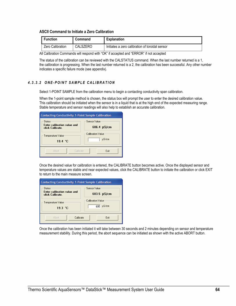
Thermo Scientific AquaSensors™ DataStick™ Measurement System User Guide 64
ASCII Command to Initiate a Zero Calibration
Function Command Explanation
Zero Calibration CALSZERO Initiates a zero calibration of toroidal sensor
All Calibration Commands will respond with “OK” if accepted and “ERROR” if not accepted
The status of the calibration can be reviewed with the CALSTATUS command. When the last number returned is a 1, the calibration is progressing. When the last number returned is a 2, the calibration has been successful. Any other number indicates a specific failure mode (see appendix).
4 . 3 . 3 . 2 O N E - P O I N T S A M P L E C A L I B R A T I O N
Select 1-POINT SAMPLE from the calibration menu to begin a contacting conductivity span calibration.
When the 1-point sample method is chosen, the status box will prompt the user to enter the desired calibration value. This calibration should be initiated when the sensor is in a liquid that is at the high end of the expected measuring range. Stable temperature and sensor readings will also help to establish an accurate calibration.
Once the desired value for calibration is entered, the CALIBRATE button becomes active. Once the displayed sensor and temperature values are stable and near expected values, click the CALIBRATE button to initiate the calibration or click EXIT to return to the main measure screen.
Once the calibration has been initiated it will take between 30 seconds and 2 minutes depending on sensor and temperature measurement stability. During this period, the abort sequence can be initiated as shown with the active ABORT button.

Thermo Scientific AquaSensors™ DataStick™ Measurement System User Guide 65
.
When the point has been successfully calibrated, measured values will be based on the new calibration. The rate of change in reading from the old measured value to the new will be dependent on the sensor filter value that is entered in the configuration menu.
Exiting the calibration menu will return the user to the measure screen.
ASCII Command to initiate a 1-Point Sample Calibration
Function Command Explanation
1-Point Sample CALS1PS Initiates a 1-point calibration All Calibration Commands will respond with “OK” if accepted and “ERROR” if not accepted
The status of the calibration can be reviewed with the CALSTATUS command. When the last number returned is a 1, the calibration is in process. When the last number returned is a 2, the calibration has been successful. Any other number indicates a specific failure mode (see appendix).
4.3.4 Contacting Conductivity Maintenance Contacting conductivity cells must be kept clean to maintain accuracy. Even a thin film of oil or mineral deposits on the electrodes can cause significant loss of span.
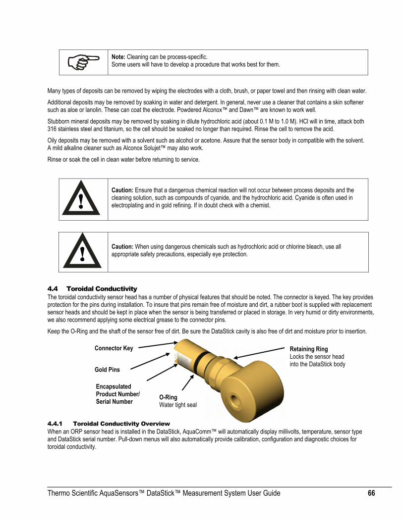
Thermo Scientific AquaSensors™ DataStick™ Measurement System User Guide 66
Note: Cleaning can be process-specific. Some users will have to develop a procedure that works best for them.
Many types of deposits can be removed by wiping the electrodes with a cloth, brush, or paper towel and then rinsing with clean water.
Additional deposits may be removed by soaking in water and detergent. In general, never use a cleaner that contains a skin softener such as aloe or lanolin. These can coat the electrode. Powdered Alconox™ and Dawn™ are known to work well.
Stubborn mineral deposits may be removed by soaking in dilute hydrochloric acid (about 0.1 M to 1.0 M). HCl will in time, attack both 316 stainless steel and titanium, so the cell should be soaked no longer than required. Rinse the cell to remove the acid.
Oily deposits may be removed with a solvent such as alcohol or acetone. Assure that the sensor body in compatible with the solvent. A mild alkaline cleaner such as Alconox Solujet™ may also work.
Rinse or soak the cell in clean water before returning to service.
Caution: Ensure that a dangerous chemical reaction will not occur between process deposits and the cleaning solution, such as compounds of cyanide, and the hydrochloric acid. Cyanide is often used in electroplating and in gold refining. If in doubt check with a chemist.
Caution: When using dangerous chemicals such as hydrochloric acid or chlorine bleach, use all appropriate safety precautions, especially eye protection.
4.4 Toroidal Conductivity The toroidal conductivity sensor head has a number of physical features that should be noted. The connector is keyed. The key provides protection for the pins during installation. To insure that pins remain free of moisture and dirt, a rubber boot is supplied with replacement sensor heads and should be kept in place when the sensor is being transferred or placed in storage. In very humid or dirty environments, we also recommend applying some electrical grease to the connector pins.
Keep the O-Ring and the shaft of the sensor free of dirt. Be sure the DataStick cavity is also free of dirt and moisture prior to insertion.
4.4.1 Toroidal Conductivity Overview When an ORP sensor head is installed in the DataStick, AquaComm™ will automatically display millivolts, temperature, sensor type and DataStick serial number. Pull-down menus will also automatically provide calibration, configuration and diagnostic choices for toroidal conductivity.
Connector Key
Encapsulated Product Number/ Serial Number
Gold Pins
O-Ring Water tight seal
Retaining Ring Locks the sensor head into the DataStick body

Thermo Scientific AquaSensors™ DataStick™ Measurement System User Guide 67
Factory default configurations for an Toroidal sensor heads are:
• Units of measure: µS/cm (options include %, ppm and MΩ·cm)
• Units for temperature: °C (options include °F)
• Sensor Filter: 1 Second (options include 0 to 100 seconds in 1 second increments)
• Temperature Filter: 1 Second (options include 0 to 100 seconds in 1 second increments)
• Reference Temperature: 25°C (options include 0°C to 100°C)
• Compensation Slope: 2% / °C (options include 0 to 9.9 %/°C)
• Concentration Table (10 Points Capability): Point 1 is (0 µS/cm, 0%), Point 2 is (20,000 µS/cm, 99.99%) When configuration information is changed in a DataStick, the information remains with the DataStick. If a new sensor head is installed, the configuration will remain as programmed by the user. It will not revert to default values.
Calibration options for the toroidal conductivity sensor are:
• 1-point Sample Calibration: Desired reading is entered for one sample to adjust measurement offset.
• Zero: Sets the zero point for the sensor in dry air. Be sure the sensor is clean before doing this one.
Calibration options for temperature are:
• 1-point Sample Calibration: Desired reading is entered for one sample to adjust measurement offset.
4.4.2 Configuration of Toroidal Sensors The AquaComm™ CONFIGURE functions can be accessed from a pull-down menu that automatically changes based on the sensor type connected to the DataStick. When a toroidal sensor is connected, settings for data filters, units of measure, reference temperature, temperature compensation and a 10-point concentration table can be viewed or changed.
4 . 4 . 2 . 1 S E N S O R F I L T E R
Select SENSOR FILTER from the Configuration pull-down menu to view or change the sensor filter constant.

Thermo Scientific AquaSensors™ DataStick™ Measurement System User Guide 68
The filter setting can be changed by selecting the edit box and typing in the desired constant. To accept the change, click OK. To abort the change, click CANCEL.
If the sensor filter is set to 5 seconds, it will take 5 seconds to reach 90% of the final value when the reading changes. Measurements are averaged to reduce periodic variations.
The default filter setting is 1 second and the maximum filter is 100 seconds. Use zero seconds for a completely unfiltered reading.
4 . 4 . 2 . 2 T E M P E R A T U R E F I L T E R
Select TEMPERATURE FILTER from the Configuration pull-down menu to view or change the temperature filter constant.
The filter setting can be changed by selecting the edit box and typing in the desired constant. To accept the change, click OK. To abort the change, click CANCEL.
If the temperature filter is set to 5 seconds, it will take 5 seconds to reach 90% of the final value when the reading changes. Measurements are averaged to reduce periodic variations.
The default filter setting is 1 second and the maximum filter is 100 seconds. Use zero seconds for a completely unfiltered reading.
The toroidal sensor head has significant mass and although the temperature element is located as close to the process as possible, temperature readings can take up to 40 minutes to reach steady state when exposed to extreme temperature changes. This is important to note when calibrating the sensor.
Although temperature and sensor filter constants are independently controlled the best results are generally achieved when both filters are set to the same constant.

Thermo Scientific AquaSensors™ DataStick™ Measurement System User Guide 69
ASCII Commands to View Sensor and Temperature Filter Settings
Function Command Response Explanation
Get Sensor Filter GSFIL A number between 0 and 100. Number of seconds.
Get Temp Filter GTFIL A number between 0 and 100. Number of seconds.
ASCII Commands to Set Sensor and Temperature Filter Settings
Function Command Explanation
Set Sensor Filter SSFIL X Where X is a number between 0 and 100. Units are in seconds.
Set Temp Filter STFIL X Where X is a number between 0 and 100. Units are in seconds.
All Set Commands will respond with “OK” if accepted and “ERROR” if not accepted
4 . 4 . 2 . 3 S E N S O R U N I T S
Select SENSOR UNITS from the Configuration pull-down menu to view or change units of measure.
Units shown in the sensor units window are active. To change units or to review options, scroll the selection list. Click on the desired units of measure to place the new choice in the sensor units window. To accept the change, click OK. To abort the change, click CANCEL.
For toroidal conductivity sensors, conductivity measurements can be set to conductivity in μS/cm, concentration in %, total dissolved solids in ppm and resistivity in MΩ·cm.
Default units of measure are µS/cm.
Concentration measurements are converted from the data points entered in a 10-point concentration table that can be viewed and edited from the Configuration pull-down menu.
ASCII Commands to View Sensor units
Function Command Response Explanation
View Sensor Units GSUNITS 0 Data reported in µS/cm units
1 Data reported in % concentration
2 Data reported in ppm (total dissolved solids)
3 Data reported in MΩ·cm units

Thermo Scientific AquaSensors™ DataStick™ Measurement System User Guide 70
ASCII Commands to Set Sensor units
Function Command Explanation
Set to µS/cm SSUNITS 0 Sensor data will be reported in µS/cm units
Set to % SSUNITS 1 Sensor data will be reported in % units
Set to ppm SSUNITS 2 Sensor data will be reported in ppm units
Set to MΩ·cm SSUNITS 3 Sensor data will be reported in MΩ·cm units
All Set Commands will respond with “OK” if accepted and “ERROR” if not accepted
4 . 4 . 2 . 4 T E M P E R A T U R E U N I T S
Select TEMPERATURE UNITS from the Configuration pull-down menu to view or change units of measure.
Units shown in the temperature units window are active. To change units or to review options, scroll the selection list. Click on the desired units of measure to place the new choice in the sensor units window. To accept the change, click OK. To abort the change, click CANCEL.
Temperature can be displayed in °C or °F. Default units are °C.
ASCII Commands to View Temperature units
Function Command Response Explanation
View Temperature Units GTUNITS 0 Data reported in °C
1 Data reported in °F
ASCII Commands to Set Temperature units Function Command Explanation
Set °C STUNITS 0 Sensor data will be reported in °C
Set °F STUNITS 1 Sensor data will be reported in °F
All Set Commands will respond with “OK” if accepted and “ERROR” if not accepted

Thermo Scientific AquaSensors™ DataStick™ Measurement System User Guide 71
4 . 4 . 2 . 5 C O N D U C T I V I T Y T E M P E R A T U R E C O M P E N S A T I O N T Y P E
The commands in this section are available in DataStick firmware D3.32 or later. The DataStick firmware version can be obtained using the GCVSN command.
ASCII Command to View Conductivity Temperature Compensation Type Function Command Response Explanation
0 The type of temperature compensation used is Linear (default)
1 The type of temperature compensation used is Natural Water
View conductivity temperature compensation type
GCTCTYPE
2 The type of temperature compensation used is None
ASCII Commands to Set Conductivity Temperature Compensation Type Function Command Explanation
Set conductivity temperature compensation type to Linear
SCTCTYPE 0 The type of temperature compensation used will be Linear and it will be based on the reference temperature and slope set with the SCRTEMP and SCCSLOPE commands, respectively
Set conductivity temperature compensation type to Natural Water
SCTCTYPE 1 The type of temperature compensation used will be Natural Water
Set conductivity temperature compensation type to None
SCTCTYPE 2 The type of temperature compensation used will be None
All Set Commands will respond with “OK” if accepted and “ERROR” if not accepted.
4 . 4 . 2 . 6 C O N D U C T I V I T Y R E F E R E N C E T E M P E R A T U R E
Select REFERENCE TEMPERATURE from the Configuration pull-down menu to view or change the conductivity reference temperature.
The setting can be changed by selecting the edit box and typing the desired number. To accept the change, click OK. To abort the change, click CANCEL.
The default reference temperature for conductivity is 25°C. The system will accept any number between 0 and 100 with up to one decimal place.
Edit the reference temperature by typing a new value in the edit box and clicking OK.

Thermo Scientific AquaSensors™ DataStick™ Measurement System User Guide 72
ASCII Command to View Conductivity Reference Temperature
Function Command Response Explanation
Get Reference GCRTEMP A number between 0 and 100 Data reported in °C
ASCII Command to Set Conductivity Reference Temperature
Function Command Explanation
Set Reference SCRTEMP X Where X is a number between 0 and 100. Units are in °C
All Set Commands will respond with “OK” if accepted and “ERROR” if not accepted
4 . 4 . 2 . 7 C O N D U C T I V I T Y T E M P E R A T U R E C O M P E N S A T I O N S L O P E
Select COMPENSATION SLOPE from the configuration menu to view or change the compensation slope for conductivity measurements.
The default compensation slope is 2.00%/°C. The system will accept any number from 0 to 9.9 with up to two decimal places.
The setting can be changed by selecting the edit box and typing the desired number. To accept the change, click OK. To abort the change, click CANCEL.
The reference can be changed to any temperature between 0°C to 100°C with one-tenth degree resolution. Edit the reference temperature by typing a new value in the edit box and clicking OK.
ASCII Command to View Conductivity Slope and Reference Temperature
Function Command Response Explanation
Get Slope GCCSLOPE A number between 0 and 9.9 Data reported in %/°C
Get Reference GCRTEMP A number between 0 and 100 Data reported in °C
ASCII Command to Set Conductivity Slope and Reference Temperature Function Command Explanation
Set Slope SCCSLOPE X Where X is a number between 0 and 9.9. Units are in %/°C
Set Reference SCRTEMP X Where X is a number between 0 and 100. Units are in °C
All Set Commands will respond with “OK” if accepted and “ERROR” if not accepted

Thermo Scientific AquaSensors™ DataStick™ Measurement System User Guide 73
4 . 4 . 2 . 8 T E N P O I N T C O N C E N T R A T I O N T A B L E E N T R I E S
Select CONCENTRATION TABLE from the configuration menu to view or change any or all of the points in the table.
When selecting the ten-point concentration table, there will be an automatic update of each of the 10 points before any editing or scrolling of the table can occur. This scan takes about 10 seconds.
The concentration table coordinates must be monotonic. Conductivity must increase with each point. Concentration can either increase or decrease with each point. The table must start at POINT 1 and continue incrementally from there. Unused points (except POINT 1) have zero, zero coordinates.
Current entries can be viewed by scrolling up and down on the “Number” window.
Table entries for specific chemicals are available from Thermo Fisher Scientific Customer Service on request.
The default concentration table is set up as shown in Table 1. The numbers can be viewed by scrolling the up/down arrows.
Table 3: 10 Point Conductivity Vs. Concentration Table
Point Conductivity (µS/cm)
Concentration %
1 0 0 2 20,000 99.99 3 0 0 4 0 0 5 0 0 6 0 0 7 0 0 8 0 0 9 0 0 10 0 0
The following example shows how to change and add data points to the table. In this case, POINT 2 is changed and POINTS 3 and 4 are added.
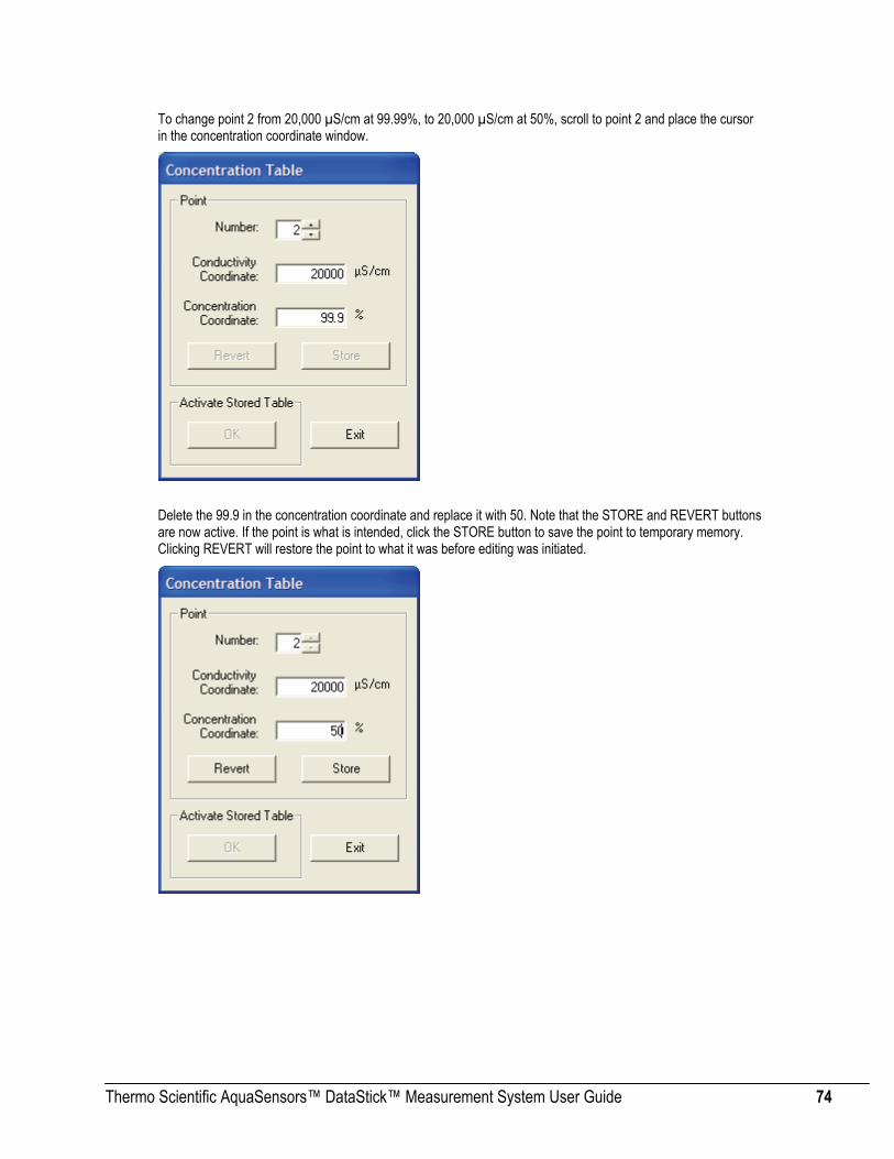
Thermo Scientific AquaSensors™ DataStick™ Measurement System User Guide 74
To change point 2 from 20,000 µS/cm at 99.99%, to 20,000 µS/cm at 50%, scroll to point 2 and place the cursor in the concentration coordinate window.
Delete the 99.9 in the concentration coordinate and replace it with 50. Note that the STORE and REVERT buttons are now active. If the point is what is intended, click the STORE button to save the point to temporary memory. Clicking REVERT will restore the point to what it was before editing was initiated.
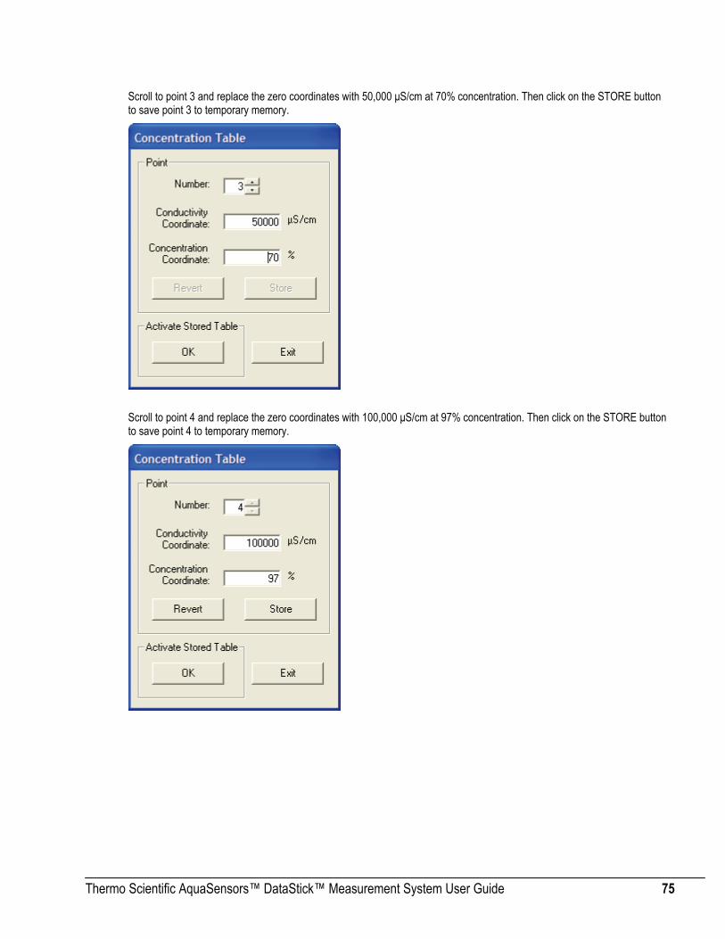
Thermo Scientific AquaSensors™ DataStick™ Measurement System User Guide 75
Scroll to point 3 and replace the zero coordinates with 50,000 μS/cm at 70% concentration. Then click on the STORE button to save point 3 to temporary memory.
Scroll to point 4 and replace the zero coordinates with 100,000 μS/cm at 97% concentration. Then click on the STORE button to save point 4 to temporary memory.

Thermo Scientific AquaSensors™ DataStick™ Measurement System User Guide 76
Data for points 5 through 10 should be zero. Data stored in temporary memory can now be permanently stored using the ACTIVATE STORED TABLE button.
If any error messages are shown, review the data points to be sure they are monotonic, that conductivity increases from point 1 and that concentration increases or decreases from point 1.
Once the table has been activated, use the EXIT button and return to the main measure menu.
Table entries for specific chemicals are available from Thermo Fisher Scientific Customer Service on request.
The table entries made in this example are shown in Table 2.
Table 4: Concentration Vs Conductivity after Editing Point Conductivity (µS/cm) Concentration %
1 0 0 2 20,000 50 3 50,000 70 4 100,000 97 5 0 0 6 0 0 7 0 0 8 0 0 9 0 0 10 0 0
When the units of measure are set to “%” the conversion from conductivity to concentration will make use of the entered table and will present the readings as shown.

Thermo Scientific AquaSensors™ DataStick™ Measurement System User Guide 77
Inside the DataStick there are two concentration tables; the scratch table and the working table. The scratch table is used to store the points written with the SUPNT command. If the points in the scratch table are valid, they are copied to the working table when the SUTBL command is used. The points in the working table are used to convert the measured conductivity value into a concentration value.
The points in the scratch table can be read using the GSPNT command. The GSPNT command is available in DataStick firmware version D3.21 or later. The DataStick firmware version can be obtained using the GCVSN command.
The points in the working table can be read using the GUPNT command. A point read from the working table using the GUPNT command is automatically written to the scratch table. This helps to insure that the scratch table is always known and valid.
Figure 10. The inner workings of the User-Entered Concentration Table.
For the scratch table to be considered valid, the following must be true:
1. All successive conductivity point values must be monotonic and increasing and be within the bounds of 0 to 2,000,000.0 µS/cm.
2. The concentration values must be monotonic and either increasing or decreasing and be within the bounds of 0 to 99.99%.
3. If fewer than ten points are entered, then the scratch table must be terminated with a last point containing zero values.
Provided the above criteria are met, the points in the scratch table are transferred to the working table when the SUTBL command is used; otherwise the current working table is retained.
0
Cond Conc
0 0
20000 99.99 1
0 0 2
0 0 3
0 0 4
0 0 5
0 0 6
0 0 7
0 0 8
0 0 9
Scratch Table
SUTBL (if scratch table
is valid) Conductivity
scaling
User
GUPNT
GSPNT
SUPNT
0
Cond Conc
0
20000 99.99 1
2
3
4
5
6
7
8
9
Working Table
0
0
0
0
0
0
0
0
0
0
0
0
0
0
0
0
0

Thermo Scientific AquaSensors™ DataStick™ Measurement System User Guide 78
ASCII Command to View Concentration Table Entries Function Command Response Explanation
Get Point from working table GUPNT X Conductivity, Concentration X is a point from 0 to 9
Get point from scratch table GSPNT X Conductivity, Concentration X is a point from 0 to 9
ASCII Command to Set a Concentration Table Entry
Function Command Explanation
Set Point in scratch table SUPNT X Y Z
X=point number. Y=conductivity in μS/cm, Z=concentration in %
This function will put individual points in “temporary memory”. Entries will not become active until the full table is set with the SUTBL command.
Set Table SUTBL
Activates new point entries.
Will return ERROR if stored points for new table are not valid.
Will return OK if the new table is accepted.
All Set Commands will respond with “OK” if accepted and “ERROR” if not accepted
4.4.3 Toroidal Conductivity Calibration When a toroidal sensor is connected to the DataStick, calibration choices specific to toroidal conductivity are automatically available. After a calibration, the sensor-head can be moved to another DataStick and measurement accuracy will be maintained.
Sensors are calibrated at the factory. When field calibrations are necessary the ZERO calibration can be made when the sensor is dry and out of the process. 1-POINT SAMPLE calibration can be done when the sensor is in process liquid.
4 . 4 . 3 . 1 Z E R O C A L I B R A T I O N
Select ZERO from the calibration menu to begin the toroidal conductivity zero calibration.
A zero calibration is applied to a sensor placed in dry air. The calibration establishes the zero for the measurement system and will require more than 1 minute to complete. Please be patient.
Suspend the sensor in dry air, away from surfaces. Be sure that the sensor body is dry by wiping it clean with a dry rag. For best results, wait for the sensor reading to reach a steady state. If the sensor is being calibrated for the first time, the reading may be as high as 100 μS/cm. In most situations however, the sensor will already have a zero calibration stored in it, which may require some periodic adjustment.

Thermo Scientific AquaSensors™ DataStick™ Measurement System User Guide 79
Initiate the zero calibration by clicking the CALIBRATE button.
Once the calibration has been initiated it will take approximately 1 to 2 minutes. During this period, the abort sequence can be initiated as shown with the active Abort button.
When the point has been successfully calibrated, measured values will be based on the new zero. The rate of change in reading from the old measured value to the new will be dependent on the sensor filter value that is entered in the configuration menu.
Exiting the calibration menu will return the user to the measure screen.

Thermo Scientific AquaSensors™ DataStick™ Measurement System User Guide 80
ASCII Command to Initiate a Toroidal Zero Calibration
Function Command Explanation
Zero Calibration CALSZERO Initiates a zero calibration of toroidal sensor
All Calibration Commands will respond with “OK” if accepted and “ERROR” if not accepted
The status of the calibration can be reviewed with the CALSTATUS command. When the last number returned is a 1, the calibration is progressing. When the last number returned is a 2, the calibration has been successful. Any other number indicates a specific failure mode (see appendix).
4 . 4 . 3 . 2 O N E - P O I N T S A M P L E C A L I B R A T I O N
Select 1-POINT SAMPLE from the calibration menu to begin a toroidal conductivity span calibration.
When the 1-point sample method is chosen, the status box will prompt the user to enter the desired calibration value. This calibration should be initiated when the sensor is in a liquid that is at the high end of the expected measuring range. Stable temperature and sensor readings will also help to establish an accurate calibration.
Once the desired value for calibration is entered, the CALIBRATE button becomes active. Once the displayed sensor and temperature values are stable and near expected values, click the CALIBRATE button to initiate the calibration or click EXIT to return to the main measure screen.
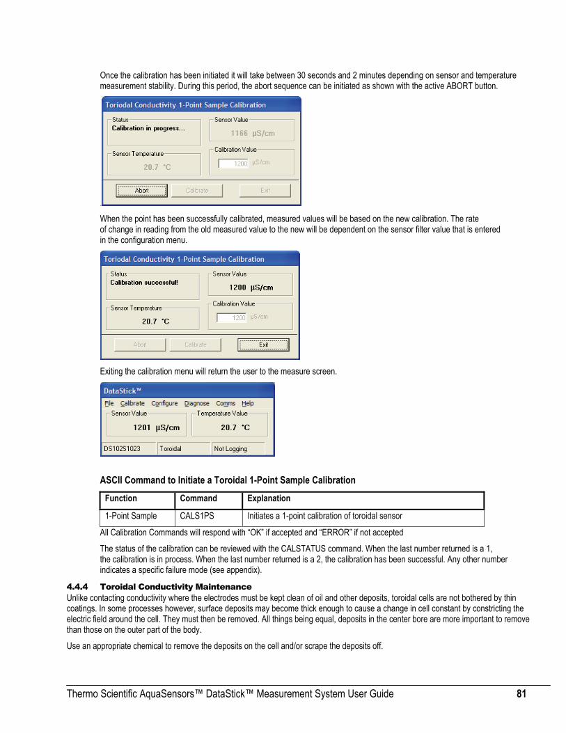
Thermo Scientific AquaSensors™ DataStick™ Measurement System User Guide 81
Once the calibration has been initiated it will take between 30 seconds and 2 minutes depending on sensor and temperature measurement stability. During this period, the abort sequence can be initiated as shown with the active ABORT button.
. When the point has been successfully calibrated, measured values will be based on the new calibration. The rate of change in reading from the old measured value to the new will be dependent on the sensor filter value that is entered in the configuration menu.
Exiting the calibration menu will return the user to the measure screen.
ASCII Command to Initiate a Toroidal 1-Point Sample Calibration
Function Command Explanation
1-Point Sample CALS1PS Initiates a 1-point calibration of toroidal sensor
All Calibration Commands will respond with “OK” if accepted and “ERROR” if not accepted
The status of the calibration can be reviewed with the CALSTATUS command. When the last number returned is a 1, the calibration is in process. When the last number returned is a 2, the calibration has been successful. Any other number indicates a specific failure mode (see appendix).
4.4.4 Toroidal Conductivity Maintenance Unlike contacting conductivity where the electrodes must be kept clean of oil and other deposits, toroidal cells are not bothered by thin coatings. In some processes however, surface deposits may become thick enough to cause a change in cell constant by constricting the electric field around the cell. They must then be removed. All things being equal, deposits in the center bore are more important to remove than those on the outer part of the body.
Use an appropriate chemical to remove the deposits on the cell and/or scrape the deposits off.

Thermo Scientific AquaSensors™ DataStick™ Measurement System User Guide 82
Note: Although toroidal conductivity cells are exceptionally robust, they can be damaged by physical abuse, such as being struck against a hard surface.
4.5 Dissolved Oxygen (PPM and PPB) and Ozone The Dissolved Oxygen and Ozone sensor heads have a number of physical features that should be noted. The connector is keyed. The key provides protection for the pins during installation. To insure that pins remain free of moisture and dirt, a rubber boot is supplied with replacement sensor heads and should be kept in place when the sensor is being transferred or placed in storage. In very humid or dirty environments, we also recommend applying some electrical grease to the connector pins.
Keep the O-Ring and the shaft of the sensor free of dirt. Be sure the DataStick cavity is also free of dirt and moisture prior to insertion.
4.5.1 Dissolved Oxygen / Ozone Interface Overview When an Dissolved Oxygen / Ozone sensor heads are installed in the DataStick, AquaComm™ will automatically display ppm, temperature, sensor type and DataStick serial number. Pull-down menus will also automatically provide calibration, configuration and diagnostic choices.
Factory default configurations for a dissolved oxygen or ozone sensor head are:
• Units of measure: ppm ) (options include % and ppb)
• Units for temperature: °C (options include °F)
• Sensor Filter: 1 Second (options include 0 to 100 seconds in 1 second increments)
• Temperature Filter: 1 Second (options include 0 to 100 seconds in 1 second increments)
• Salinity: 0 mS/cm (options from 0 to 999.9 mS/cm)
• Atmospheric Pressure: 760 mmHg (options from 539.2 to 792.4 mmHg)
Connector Key
Retaining Ring Locks the sensor head into the DataStick body
Encapsulated Product Number/ Serial Number
Gold Pins
Replaceable Membrane Cap
O-Ring Water tight seal

Thermo Scientific AquaSensors™ DataStick™ Measurement System User Guide 83
When configuration information is changed in a DataStick, the information remains with the DataStick. If a new sensor head is installed, the configuration will remain as programmed by the user. It will not revert to default values.
Calibration options Dissolved Oxygen and Ozone sensors are:
• 1-point Sample Calibration: Desired reading is entered for one sample to adjust measurement offset.
• Air Calibration: Measures the oxygen in air, compensated by the configured atmospheric pressure setting.
Calibration options for temperature are:
• 1-point Sample Calibration: Desired reading is entered for one sample to adjust measurement offset.
4.5.2 Configuration of Dissolved Oxygen and Ozone Sensor Heads The AquaComm™ CONFIGURE functions can be accessed from a pull-down menu that automatically changes based on the sensor type connected to the DataStick. When a dissolved oxygen sensor is connected, settings for data filters, units of measure, atmospheric pressure, salinity, and temperature compensation can be viewed or changed.
4 . 5 . 2 . 1 S E N S O R F I L T E R
Select SENSOR FILTER from the Configuration pull-down menu to view or change the sensor filter constant.
The filter setting can be changed by selecting the edit box and typing in the desired constant. To accept the change, click OK. To abort the change, click CANCEL.
If the sensor filter is set to 5 seconds, it will take 5 seconds to reach 90% of the final value when the reading changes. Measurements are averaged to reduce periodic variations.
The default filter setting is 1 second and the maximum filter is 100 seconds. Use zero seconds for a completely unfiltered reading.
4 . 5 . 2 . 2 T E M P E R A T U R E F I L T E R
Select TEMPERATURE FILTER from the Configuration pull-down menu to view or change the temperature filter constant.
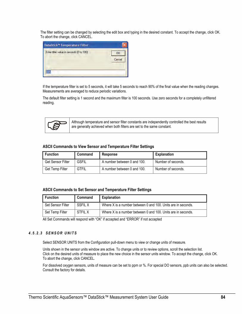
Thermo Scientific AquaSensors™ DataStick™ Measurement System User Guide 84
The filter setting can be changed by selecting the edit box and typing in the desired constant. To accept the change, click OK. To abort the change, click CANCEL.
If the temperature filter is set to 5 seconds, it will take 5 seconds to reach 90% of the final value when the reading changes. Measurements are averaged to reduce periodic variations.
The default filter setting is 1 second and the maximum filter is 100 seconds. Use zero seconds for a completely unfiltered reading.
ASCII Commands to View Sensor and Temperature Filter Settings
Function Command Response Explanation
Get Sensor Filter GSFIL A number between 0 and 100. Number of seconds.
Get Temp Filter GTFIL A number between 0 and 100. Number of seconds.
ASCII Commands to Set Sensor and Temperature Filter Settings
Function Command Explanation
Set Sensor Filter SSFIL X Where X is a number between 0 and 100. Units are in seconds.
Set Temp Filter STFIL X Where X is a number between 0 and 100. Units are in seconds.
All Set Commands will respond with “OK” if accepted and “ERROR” if not accepted
4 . 5 . 2 . 3 S E N S O R U N I T S
Select SENSOR UNITS from the Configuration pull-down menu to view or change units of measure.
Units shown in the sensor units window are active. To change units or to review options, scroll the selection list. Click on the desired units of measure to place the new choice in the sensor units window. To accept the change, click OK. To abort the change, click CANCEL.
For dissolved oxygen sensors, units of measure can be set to ppm or %. For special DO sensors, ppb units can also be selected. Consult the factory for details.
Although temperature and sensor filter constants are independently controlled the best results are generally achieved when both filters are set to the same constant.

Thermo Scientific AquaSensors™ DataStick™ Measurement System User Guide 85
Default units of measure are ppm.
ASCII Commands to View Sensor units
Function Command Response Explanation
View Sensor Units GSUNITS 0 Data reported in ppm units
1 Data reported in % concentration
ASCII Commands to Set Sensor units
Function Command Explanation
Set to ppm SSUNITS 0 Sensor data will be reported in ppm units
Set to % SSUNITS 1 Sensor data will be reported in % concentration
All Set Commands will respond with “OK” if accepted and “ERROR” if not accepted
4 . 5 . 2 . 4 T E M P E R A T U R E U N I T S
Select TEMPERATURE UNITS from the Configuration pull-down menu to view or change units of measure.
Units shown in the temperature units window are active. To change units or to review options, scroll the selection list. Click on the desired units of measure to place the new choice in the sensor units window. To accept the change, click OK. To abort the change, click CANCEL.
Temperature can be displayed in °C or °F. Default units are °C.
ASCII Commands to View Temperature units Function Command Response Explanation
View Temperature Units GTUNITS 0 Data reported in °C
1 Data reported in °F
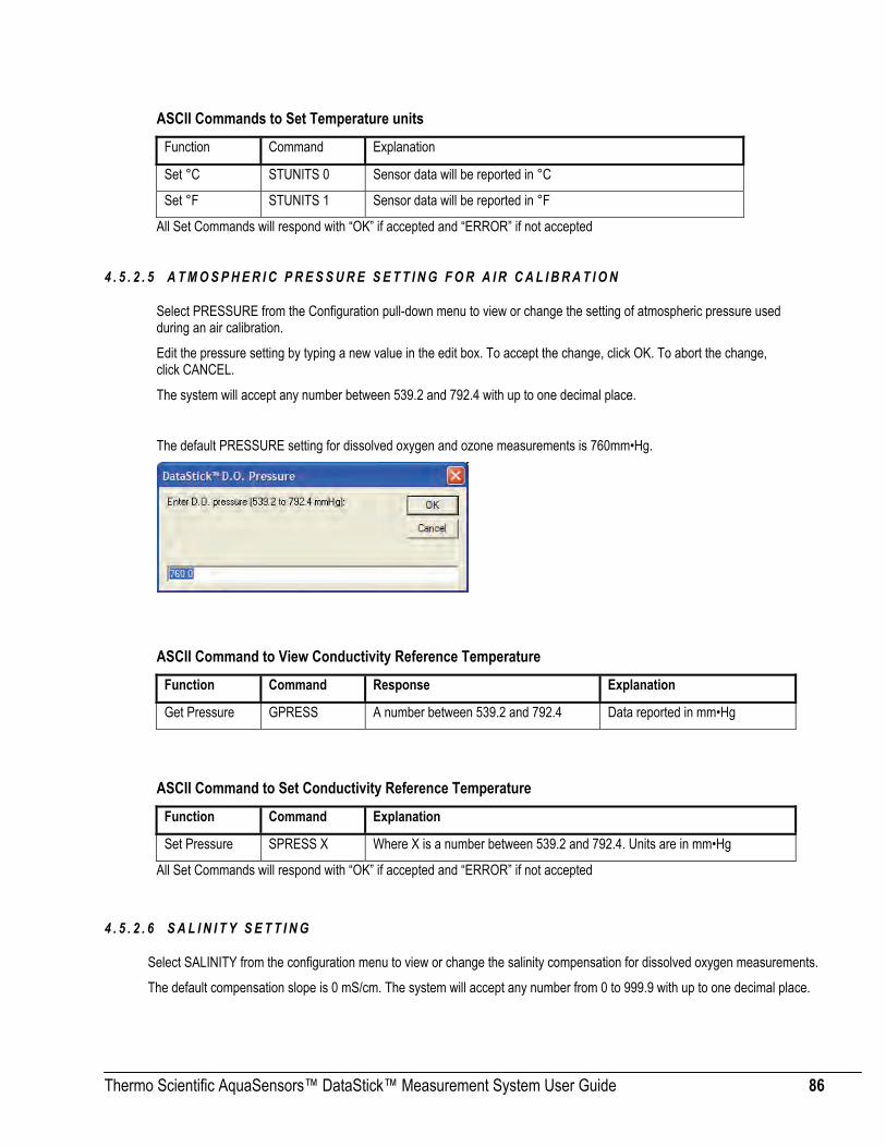
Thermo Scientific AquaSensors™ DataStick™ Measurement System User Guide 86
ASCII Commands to Set Temperature units Function Command Explanation
Set °C STUNITS 0 Sensor data will be reported in °C
Set °F STUNITS 1 Sensor data will be reported in °F
All Set Commands will respond with “OK” if accepted and “ERROR” if not accepted
4 . 5 . 2 . 5 A T M O S P H E R I C P R E S S U R E S E T T I N G F O R A I R C A L I B R A T I O N
Select PRESSURE from the Configuration pull-down menu to view or change the setting of atmospheric pressure used during an air calibration.
Edit the pressure setting by typing a new value in the edit box. To accept the change, click OK. To abort the change, click CANCEL.
The system will accept any number between 539.2 and 792.4 with up to one decimal place.
The default PRESSURE setting for dissolved oxygen and ozone measurements is 760mm•Hg.
ASCII Command to View Conductivity Reference Temperature
Function Command Response Explanation
Get Pressure GPRESS A number between 539.2 and 792.4 Data reported in mm•Hg
ASCII Command to Set Conductivity Reference Temperature
Function Command Explanation
Set Pressure SPRESS X Where X is a number between 539.2 and 792.4. Units are in mm•Hg
All Set Commands will respond with “OK” if accepted and “ERROR” if not accepted
4 . 5 . 2 . 6 S A L I N I T Y S E T T I N G
Select SALINITY from the configuration menu to view or change the salinity compensation for dissolved oxygen measurements.
The default compensation slope is 0 mS/cm. The system will accept any number from 0 to 999.9 with up to one decimal place.

Thermo Scientific AquaSensors™ DataStick™ Measurement System User Guide 87
The setting can be changed by selecting the edit box and typing the desired number. To accept the change, click OK. To abort the change, click CANCEL.
ASCII Command to View Conductivity Slope and Reference Temperature
Function Command Response Explanation
Get Salinity GSALT A number between 0 and 999.9 Data reported in mS/cm
ASCII Command to Set Conductivity Slope and Reference Temperature
Function Command Explanation
Set Salinity SSALT X Where X is a number between 0 and 999.9. Units are in mS/cm
All Set Commands will respond with “OK” if accepted and “ERROR” if not accepted
4.5.3 Dissolved Oxygen Calibration When a DO sensor is connected to the DataStick, calibration choices specific to DO are automatically available. After a calibration, the sensor head can be moved to another DataStick and measurement accuracy will be maintained.
Sensors are calibrated at the factory. When field calibrations are necessary, Air and 1-point sample calibrations are available. For DO sensors that have not been active for several hours, it may take up to 1 hour before the reading becomes stable and accurate.

Thermo Scientific AquaSensors™ DataStick™ Measurement System User Guide 88
4 . 5 . 3 . 1 O N E - P O I N T S A M P L E C A L I B R A T I O N
Select 1-POINT SAMPLE from the calibration menu to begin a dissolved oxygen span calibration.
When the 1-point sample method is chosen, the status box will prompt the user to enter the desired calibration value. This calibration should be initiated when the sensor is in a liquid that is at the high end of the expected measuring range. Stable temperature and sensor readings will also help to establish an accurate calibration.
Once the desired value for calibration is entered, the CALIBRATE button becomes active. Once the displayed sensor and temperature values are stable and near expected values, click the CALIBRATE button to initiate the calibration or click EXIT to return to the main measure screen.
Once the calibration has been initiated it will take between 30 seconds and 2 minutes depending on sensor and temperature measurement stability. During this period, the abort sequence can be initiated as shown with the active ABORT button.
.

Thermo Scientific AquaSensors™ DataStick™ Measurement System User Guide 89
When the point has been successfully calibrated, measured values will be based on the new calibration. The rate of change in reading from the old measured value to the new will be dependent on the sensor filter value that is entered in the configuration menu.
Exiting the calibration menu will return the user to the measure screen.
ASCII Command to initiate a 1-Point Sample Calibration
Function Command Explanation
1-Point Sample CALS1PS Initiates a 1-point calibration
All Calibration Commands will respond with “OK” if accepted and “ERROR” if not accepted
The status of the calibration can be reviewed with the CALSTATUS command. When the last number returned is a 1, the calibration is in process. When the last number returned is a 2, the calibration has been successful. Any other number indicates a specific failure mode (see appendix).
4 . 5 . 3 . 2 A I R C A L I B R A T I O N
Select AIR from the calibration menu to begin a dissolved oxygen air calibration.
Hold the sensor in the air and wait for temperature and sensor readings to stabilize. Do not allow the sensor membrane to dry out.

Thermo Scientific AquaSensors™ DataStick™ Measurement System User Guide 90
Press the CALIBRATE button to initiate the calibration or click EXIT to return to the main measure screen.
Once the calibration has been initiated it will take between 30 seconds and 2 minutes depending on sensor and temperature measurement stability. During this period, the abort sequence can be initiated as shown with the active ABORT button.
.
When the point has been successfully calibrated, measured values will be based on the new calibration. The reading will be in the range of 8 ppm to 10 ppm depending on the atmospheric pressure setting. Consult dissolved oxygen tables for more specific information on expected readings after an AIR calibration.
Exiting the calibration menu will return the user to the measure screen.
ASCII Command to Initiate an Air Calibration
Function Command Explanation
1-Point Sample CALSAIR Initiates an AIR calibration for DO or Ozone sensors
All Calibration Commands will respond with “OK” if accepted and “ERROR” if not accepted
The status of the calibration can be reviewed with the CALSTATUS command. When the last number returned is a 1, the calibration is in process. When the last number returned is a 2, the calibration has been successful. Any other number indicates a specific failure mode (see appendix).
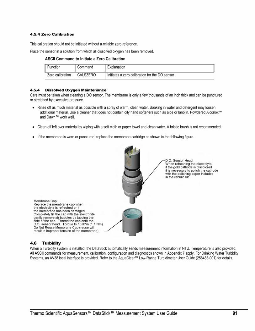
Thermo Scientific AquaSensors™ DataStick™ Measurement System User Guide 91
4.5.4 Zero Calibration This calibration should not be initiated without a reliable zero reference.
Place the sensor in a solution from which all dissolved oxygen has been removed.
ASCII Command to Initiate a Zero Calibration Function Command Explanation
Zero calibration CALSZERO Initiates a zero calibration for the DO sensor
4.5.4 Dissolved Oxygen Maintenance Care must be taken when cleaning a DO sensor. The membrane is only a few thousands of an inch thick and can be punctured or stretched by excessive pressure.
• Rinse off as much material as possible with a spray of warm, clean water. Soaking in water and detergent may loosen additional material. Use a cleaner that does not contain oily hand softeners such as aloe or lanolin. Powdered Alconox™ and Dawn™ work well.
• Clean off left over material by wiping with a soft cloth or paper towel and clean water. A bristle brush is not recommended.
• If the membrane is worn or punctured, replace the membrane cartridge as shown in the following figure.
4.6 Turbidity When a Turbidity system is installed, the DataStick automatically sends measurement information in NTU. Temperature is also provided. All ASCII commands for measurement, calibration, configuration and diagnostics shown in Appendix 7 apply. For Drinking Water Turbidity Systems, an AV38 local interface is provided. Refer to the AquaClear™ Low-Range Turbidimeter User Guide (258483-001) for details.
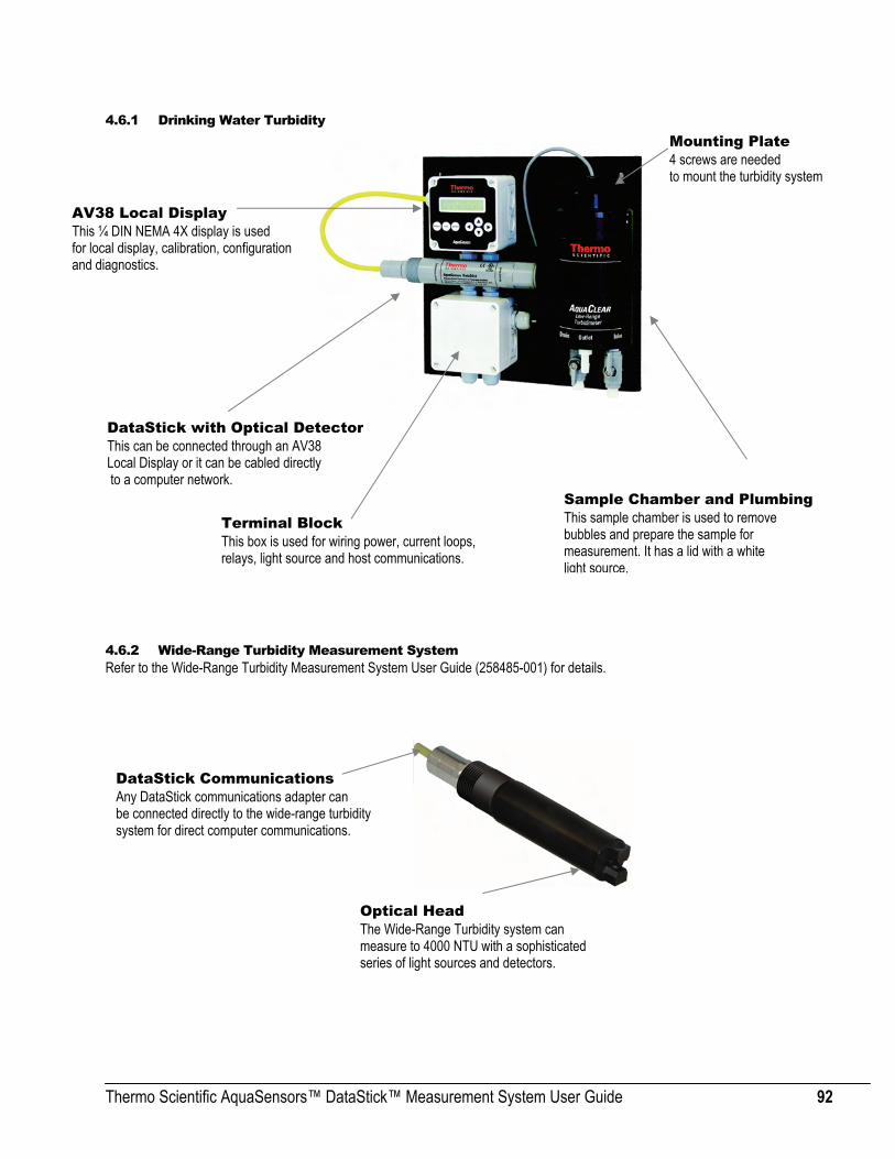
Thermo Scientific AquaSensors™ DataStick™ Measurement System User Guide 92
4.6.1 Drinking Water Turbidity
DataStick with Optical Detecto
4.6.2 Wide-Range Turbidity Measurement System Refer to the Wide-Range Turbidity Measurement System User Guide (258485-001) for details.
r This can be connected through an AV38 Local Display or it can be cabled directly to a computer network.
AV38 Local Display This ¼ DIN NEMA 4X display is used for local display, calibration, configuration and diagnostics.
Sample Chamber and Plumbing This sample chamber is used to remove bubbles and prepare the sample for measurement. It has a lid with a white light source.
Terminal Block This box is used for wiring power, current loops, relays, light source and host communications.
Mounting Plate 4 screws are needed to mount the turbidity system
Optical Head The Wide-Range Turbidity system can measure to 4000 NTU with a sophisticated series of light sources and detectors.
DataStick Communications Any DataStick communications adapter can be connected directly to the wide-range turbidity system for direct computer communications.

Thermo Scientific AquaSensors™ DataStick™ Measurement System User Guide 93
4.7 Temperature Calibration All DataStick sensor heads (transducers) measure temperature the same way and share a common calibration process.
Select TEMPERATURE from the calibration menu to begin a temperature calibration. The status box will prompt the user to enter the desired calibration value.
Once the desired value for calibration is entered, the CALIBRATE button becomes active. Once the displayed temperature value is stable and near expected values, click the CALIBRATE button to initiate the calibration or click EXIT to return to the main measure screen.
Once the calibration has been initiated it will take about 30 seconds depending on temperature measurement stability. During this period, the abort sequence can be initiated as shown with the active Abort button.

Thermo Scientific AquaSensors™ DataStick™ Measurement System User Guide 94
When the point has been successfully calibrated, measured values will be based on the new calibration. The change in reading from the old measured value to the new will be dependent on the temperature filter value that is entered in the configuration menu.
Exiting the calibration menu will return the user to the measure screen.
ASCII Command to initiate a 1-Point Temperature Calibration
Function Command Explanation
Temperature Calibration
CALST1PS Initiates a 1-point calibration of temperature
All Calibration Commands will respond with “OK” if accepted and “ERROR” if not accepted
The status of the calibration can be reviewed with the CALSTATUS command. When the last number returned is a 1, the calibration is in process. When the last number returned is a 2, the calibration has been successful. Any other number indicates a specific failure mode (see appendix).
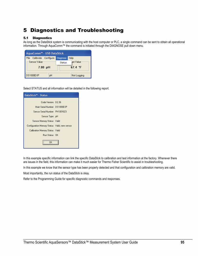
Thermo Scientific AquaSensors™ DataStick™ Measurement System User Guide 95
5 Diagnostics and Troubleshooting 5.1 Diagnostics As long as the DataStick system is communicating with the host computer or PLC, a single command can be sent to obtain all operational information. Through AquaComm™ the command is initiated through the DIAGNOSE pull down menu.
Select STATUS and all information will be detailed in the following report.
In this example specific information can link the specific DataStick to calibration and test information at the factory. Whenever there are issues in the field, this information can make it much easier for Thermo Fisher Scientific to assist in troubleshooting.
In this example we know that the sensor type has been properly detected and that configuration and calibration memory are valid.
Most importantly, the run status of the DataStick is okay.
Refer to the Programming Guide for specific diagnostic commands and responses.

Thermo Scientific AquaSensors™ DataStick™ Measurement System User Guide 96
Yes
Yes
Yes
Yes
Yes
5.2 Troubleshooting
Start
Communications OK
Detected Sensor Type OK
Detected Memory OK
Sensor Calibration OK
Measurement OK
End
No 1. Check power is properly applied. 2. Check communications wires are properly connected. 3. Check baud rate, parity and station number. 4. Check that the Comms Adapter is properly connected. Fault not found: Replace DataStick or Comms Adapter.
1. Check that the sensor head is properly connected. 2. Cycle power. 3. Reset DataStick memory. 4. Remove sensor head and inspect internal connectors (clean & dry). Fault not found: Replace Sensor Head. If problem persists, replace DataStick.
No
1. Cycle power. 2. Reset DataStick memory. Fault not found: If failure is Sensor Memory, replace Sensor Head. If failure is in Configuration or Calibration Memory, replace DataStick.
No
1. Check integrity of sensor electrodes, membranes and junctions. 2. Check sensor configuration to be sure appropriate parameters are
properly set. These include: buffer type, pressure, salinity, temperature, reference temperature, and reference slope.
3. Check that the temperature reading is correct. If it reads full-scale then the temperature element is open circuit.
4. Check that sensor and temperature readings are stable in the calibration solution. If not, wait for the sensor to reach equilibrium.
5. Check that the calibration solutions are correct. Fault not found: Refurbish or replace the sensor head.
No
1. Check sensor configuration to be sure appropriate parameters are properly set. These include: buffer type, pressure, salinity, temperature, reference temperature, and reference slope.
2. Check that the temperature reading is correct. If it reads full-scale then the temperature element is open circuit.
3. Check that the calibration solutions are correct. Fault not found: Refurbish or replace the sensor head.
No

Thermo Scientific AquaSensors™ DataStick™ Measurement System User Guide 97
5.2.1 pH Sensor Head inspection
If the glass electrode is broken replace the sensor head.
If the salt bridge junctions have dried out soak the sensor head in salt bridge storage solution for several hours, or replace it and fill the reference chamber with new reference solution.
Note: Any new sensor that has been in storage for more than a few days should be soaked in tap water or a solution of known pH for at least 30 minutes before reviewing the span and offset performance.
Note: The electrodes of any pH sensor in storage must be kept moist at all times. Protective caps should be filled with Thermo Scientific AquaSensors storage solution for best performance. The protective cap should be placed securely over the sensor head.
If the sensor passes the visual inspection, there are three basic measurement tests that can verify normal operation. The temperature measurement can be verified with an independent thermometer. Temperature comparisons should be done in liquid as it takes the sensor much longer to reach steady state in air. The pH offset can be verified in 7 pH buffer. If the reading is more that 0.5 pH units off in 7 pH buffer, then the sensor needs to be refurbished. The sensor should be stirred if the test is done in a beaker or at least the sensor head should be swirled around for 10 seconds to make sure the solution gets through the reference junction. The pH span can be verified in a sample solution that is more that 3 pH units away from 7 pH. Generally 4 pH buffer and 10 pH buffer work well. If the reading is more than 1 pH unit off then the sensor needs to be refurbished or replaced.
Make sure the correct configuration settings have been made:
• Correct Buffer Standards selected for buffer calibrations • Temperature should read within 2 degrees centigrade of the expected value
5.2.2 ORP Sensor Head inspection If the glass around the platinum electrode is broken replace the sensor head.
If the salt bridge junctions have dried out soak the sensor head in salt bridge storage solution for several hours, or replace it and fill the reference chamber with new reference solution.
Note: Any new sensor that has been in storage for more than a few days should be soaked in tap water or Thermo Scientific AquaSensors ORP Storage Solution for at least 30 minutes before reviewing the offset performance.
Note: The salt bridge of any ORP sensor in storage must be kept moist at all times. Protective caps should be filled with Thermo Scientific AquaSensors Storage Solution for best performance. The protective cap should be placed securely over the sensor head.
If the sensor passes the general inspection, there are two basic tests that can verify normal operation. If the sensor passes the visual inspection, there are two basic measurement tests that can verify normal operation. The temperature measurement can be verified with an independent thermometer. Temperature comparisons should be done in liquid as it takes the sensor much longer to reach steady state in air. The ORP measurement should be tested with a solution that is at least +200 mV. If the reading is more than 100 mV off then the sensor needs to be refurbished or replaced.

Thermo Scientific AquaSensors™ DataStick™ Measurement System User Guide 98
5.2.3 Dissolved Oxygen and Ozone Sensor Head inspection Dissolved Oxygen and Ozone sensors may take up to 30 minutes to reach correct measurement values once power is applied. The less oxygen in the electrolyte filling solution the better. Never vigorously stir or shake filling solution when replacing a cartridge. When power is first applied to a DO or Ozone sensor, the reading will show saturation and then slowly decrease to the correct value.
Make sure there are no large bubbles (over 2 mm) under the membrane and that the membrane is stretched tightly over the center (gold) electrode. Make sure the membrane cap is screwed down completely.
Make sure the correct configuration settings have been made:
• Pressure is normally set to 760 mmHg. • Salinity is normally set to 0 mS/cm • Temperature should read within 2 °C of the expected value
If the sensor has been given sufficient time after power is applied to reach the proper reading, several things can happen:
• If the sensor reads zero all the time: Replace the electrolyte and membrane cartridge. • If the sensor reads near full scale and does not come down, give it additional time. If the electrolyte was shaken
vigorously prior to filling, additional time may be needed.
When the sensor head is placed in storage, keep the membrane moist with a wetted sensor cap.
5.2.4 Contacting Conductivity Sensor Head inspection The best way to determine if a contacting conductivity sensor head requires cleaning is to connect a 1000 ohm resistor between the inner and outer electrode in a dry environment and divide it by the current cell constant are reported in the AquaComm™ configuration menu. If the measured reading is within 5% of the calculated reading, then the DataStick should be computing correctly. In liquid, if the measurement reading is too far off for a valid calibration, then the electrodes must be cleaned and be free of oils.
It is also possible that the sensor will read correctly in solutions of a specific conductivity but not at others. This can be determined by increasing the resistance between the electrodes from 100 ohms in 200 ohms steps to 5000 ohms in a dry environment. If the reading either oscillates or displays a reading that is wildly off, there is a specific measurement range that has failed. This is most likely a problem in the DataStick and not necessarily in the sensor head.
Make sure the correct configuration settings have been made:
• Reference temperature is normally set to 25 °C • Reference slope is normally set to 2 % / °C • Temperature should read within 0.5 °C of the expected value
When the sensor head is placed in storage, cap the metal electrodes to keep them clean and dry.
5.2.5 Toroidal Conductivity Sensor Head inspection A toroidal conductivity sensor measures within 1 µS/cm from 1 μS/cm to 5 S/cm. It is possible that the sensor will read correctly in solutions of a specific conductivity but not in others. This can be determined by increasing the resistance of a wire that is looped through the center hole of the sensor. If the reading oscillates or displays a reading that is wildly off with a given resistance, there is a specific measurement range that has failed. This is most likely a problem in the DataStick and not necessarily in the sensor.
Make sure the correct configuration settings have been made:
• Reference temperature is normally set to 25 °C • Reference slope is normally set to 2 % / °C • If measuring in %, make sure the concentration table entries make sense. • Temperature should read within 0.5 °C of the expected value
When the sensor head is placed in storage, cap the metal electrodes to keep them clean and dry.

Thermo Scientific AquaSensors™ DataStick™ Measurement System User Guide 99
6 Programming Guide - Commands and Responses These commands can be used to program any host computer. If programming is not desirable, Thermo Fisher Scientific offers a communications software package that can be used with most PC, PLD and PLC systems. The following ASCII text strings can be used to exercise functions and features of the DataStick measurement system. If an RS-232 ASCII communications adapter is installed, any terminal program can be used to communicate with the DataStick by typing commands and reading the replies.
The DataStick responds to commands from a host computer system except when a CALL command has been initiated to request periodic data. These include CALL, CSNSR and CTEMP commands. The ESC key halts all CALL commands. Commands that are recognized and accepted return an “OK”. Commands that are not return accepted return an “ERROR”.
The form of any command is:
KEYWORD P0 P1 P2….Pn [CR]; where the KEYWORD is the command identifier, the space character is the parameter separator, Pn is a command parameter, and [CR] is carriage return, the command terminator. All commands are sent in an ASCII format.
Communication setups vary depending on the protocol chosen.
• RS-232 ASCII: 9600 Baud, 8 data bits, no parity, 1 stop bit. • RS-232 DF1: Selectable baud rate and parity using a Thermo Scientific AquaSensors software utility. • RS-485 MODBUS: Station address, baud rate, parity are selectable using a Thermo Scientific AquaSensors
software utility. • Ethernet, USB, DeviceNet, Profibus do not require communications setup.
Commands and responses are organized in the following tables:
Table 5: Data Reporting Table 6: Changing Measurement and Configuration Settings Table 7: View Configuration Settings Table 8: Calibration Commands Table 9: Diagnostic and Systems Information Table 10: Simulated Temperature Control
Please note that commands are common for each sensor type but that response codes may vary depending on the sensor connected. A 1-point sample calibration command will be the same for dissolved oxygen as it is for toroidal conductivity. This simplifies ladder logic coding for applications that presume the possibility of changes in sensor type.
Table 5: Data Reporting
Get Measurement Data for …
Using the Command Text…
And view response from the DataStick… Comments
Sensor (Main Parameter)
GSNSR Number with decimal in selected units of measure.
Obtains current sensor data at a rate defined by the host computer (Polled).
Units of measure are configured using the SSUNITS command.
Temperature
GTEMP Number with decimal in selected units of measure.
Obtains current temperature data at a rate defined by the host computer (Polled). Units of measure are configured using the STUNITS command.
Main parameter and temperature
CALL X
Sensor and temperature readings every X seconds in selected units of measure.
Obtains current sensor and temperature data every X seconds. Example: CALL 5 would return new values for the main parameter and temperature every five seconds. Reporting is halted with the ESC key.

Thermo Scientific AquaSensors™ DataStick™ Measurement System User Guide 100
Table 6: Change Measurement Configuration Settings
Change Configuration Settings for…
Using the Command Text… Where X is a number meaning… Comments
Sensor Units of Measure
SSUNITS X
PH: 0 = pH units 1 = mV units
ORP: 0 = mV
Conductivity: 0 = µS/cm 1 = % 2 = TDS 3 = MΩ•cm
DO/Ozone: 0 = ppm 1 = %
Typing “SSUNITS 3”when a toroidal conductivity sensor head is installed will set measurement units to MΩ•cm.
As different sensor heads are added to the family of DataStick measurements this list will be expanded.
Default is always zero (X = 0).
Temperature Units of Measure
STUNITS X 0 = ˚C 1 = ˚F
Typing “STUNITS 0” will set temperature units to ˚C. Default is always zero (X = 0).
Sensor Data Filter SSFIL X Filter time constant from 0 to 100 seconds. X = 0 to X = 100.
The sensor process variable will reach 90% of the final value in “X” seconds.
Temperature Data Filter STFIL X Filter time constant from 0 to 100 seconds. Integers only.
X = 0 to X = 100.
The temperature variable will reach 90% of the final value in “X” seconds. Caution: It is advised to keep the temperature and process filter constants equal.
Buffer Set for pH calibration SPHBUF X
Buffer type set for auto recognition during buffer calibration.
0 = 4, 7, 10 pH Buffers 1 = DIN Buffer Standards
pH buffer calibration: the current reading will be changed to the closest value in the buffer set selected.
DIN Buffer Standards are: 1.09, 4.65, 6.79, 9.23 and 12.75 pH
Salinity for Dissolved Oxygen Compensation SSALT X
Salinity is set from 0 to 999.9 mS/cm.
X = 0 to X = 999.9 mS/cm
Set up the average salinity for compensation of dissolved oxygen measurement.
Pressure for Dissolved Oxygen Compensation SPRESS X Pressure is set from 539.2 to 792.4 mmHg
X = 539.2 mmHg to X = 792.4 mmHg Set up the average pressure for compensation of measurement.
Conductivity Reference Temperature SCRTEMP X Conductivity reference temperature is set
from 0˚C to 100˚C. X = 0˚C to X = 100˚C Default value is 25˚C.
Conductivity Compensation Slope SCCSLOPE X Conductivity slope is set from:
X = 0 to X = 9.9% / ˚C Default is 2.0%/˚C
Customized Concentration Table
SUPNT X Y Z
Points in the table where: X is the table entry (X = 0 through 9) Y is the Conductivity value in µS/cm. Z is the Concentration value in %.
Conductivity Range: 0 to 2,000,000.0 Concentration Range: 0 to 99.99%
This table is designed to convert conductivity measurements to concentration. Currently uses a built-in Natural Water table for temperature compensation. Up to 10 points.
Customized Concentration Table SUTBL When edits to all points are complete use
SUTBL to activate the new table Entries must be monotonic with increasing conductivities.
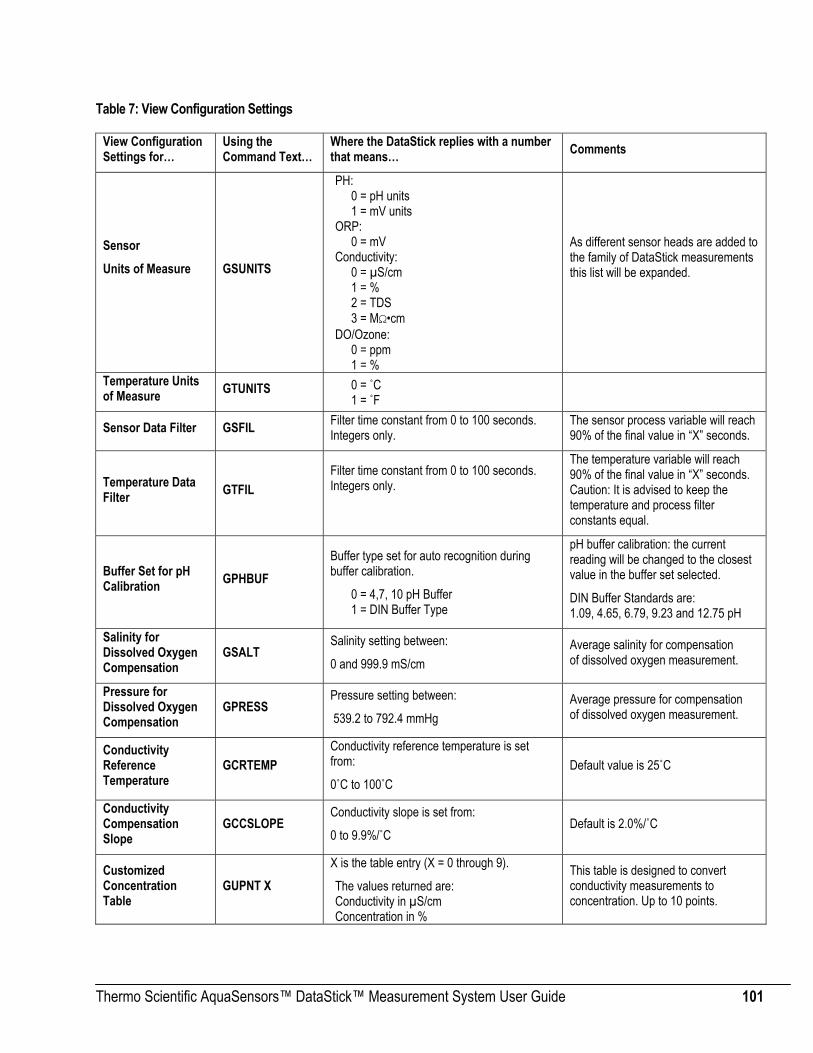
Thermo Scientific AquaSensors™ DataStick™ Measurement System User Guide 101
Table 7: View Configuration Settings
View Configuration Settings for…
Using the Command Text…
Where the DataStick replies with a number that means… Comments
Sensor Units of Measure
GSUNITS
PH: 0 = pH units 1 = mV units
ORP: 0 = mV
Conductivity: 0 = µS/cm 1 = % 2 = TDS 3 = MΩ•cm
DO/Ozone: 0 = ppm 1 = %
As different sensor heads are added to the family of DataStick measurements this list will be expanded.
Temperature Units of Measure GTUNITS 0 = ˚C
1 = ˚F
Sensor Data Filter GSFIL Filter time constant from 0 to 100 seconds. Integers only.
The sensor process variable will reach 90% of the final value in “X” seconds.
Temperature Data Filter GTFIL
Filter time constant from 0 to 100 seconds. Integers only.
The temperature variable will reach 90% of the final value in “X” seconds. Caution: It is advised to keep the temperature and process filter constants equal.
Buffer Set for pH Calibration GPHBUF
Buffer type set for auto recognition during buffer calibration.
0 = 4,7, 10 pH Buffer 1 = DIN Buffer Type
pH buffer calibration: the current reading will be changed to the closest value in the buffer set selected.
DIN Buffer Standards are: 1.09, 4.65, 6.79, 9.23 and 12.75 pH
Salinity for Dissolved Oxygen Compensation
GSALT Salinity setting between:
0 and 999.9 mS/cm Average salinity for compensation of dissolved oxygen measurement.
Pressure for Dissolved Oxygen Compensation
GPRESS Pressure setting between:
539.2 to 792.4 mmHg Average pressure for compensation of dissolved oxygen measurement.
Conductivity Reference Temperature
GCRTEMP Conductivity reference temperature is set from:
0˚C to 100˚C Default value is 25˚C
Conductivity Compensation Slope
GCCSLOPE Conductivity slope is set from:
0 to 9.9%/˚C Default is 2.0%/˚C
Customized Concentration Table
GUPNT X X is the table entry (X = 0 through 9).
The values returned are: Conductivity in µS/cm Concentration in %
This table is designed to convert conductivity measurements to concentration. Up to 10 points.
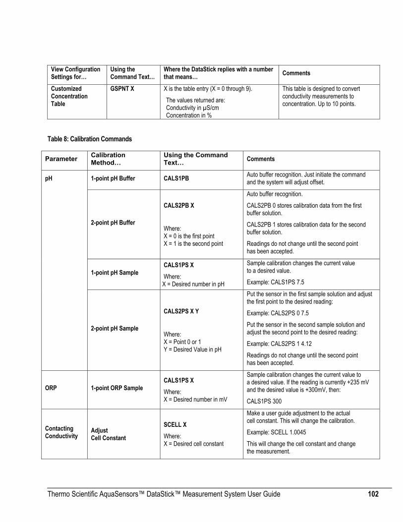
Thermo Scientific AquaSensors™ DataStick™ Measurement System User Guide 102
View Configuration Settings for…
Using the Command Text…
Where the DataStick replies with a number that means… Comments
Customized Concentration Table
GSPNT X X is the table entry (X = 0 through 9).
The values returned are: Conductivity in µS/cm Concentration in %
This table is designed to convert conductivity measurements to concentration. Up to 10 points.
Table 8: Calibration Commands
Parameter Calibration Method…
Using the Command Text… Comments
pH 1-point pH Buffer CALS1PB Auto buffer recognition. Just initiate the command and the system will adjust offset.
2-point pH Buffer
CALS2PB X
Where: X = 0 is the first point X = 1 is the second point
Auto buffer recognition.
CALS2PB 0 stores calibration data from the first buffer solution.
CALS2PB 1 stores calibration data for the second buffer solution.
Readings do not change until the second point has been accepted.
1-point pH Sample CALS1PS X Where:
X = Desired number in pH
Sample calibration changes the current value to a desired value.
Example: CALS1PS 7.5
2-point pH Sample
CALS2PS X Y
Where: X = Point 0 or 1 Y = Desired Value in pH
Put the sensor in the first sample solution and adjust the first point to the desired reading:
Example: CALS2PS 0 7.5
Put the sensor in the second sample solution and adjust the second point to the desired reading:
Example: CALS2PS 1 4.12
Readings do not change until the second point has been accepted.
ORP 1-point ORP Sample CALS1PS X Where: X = Desired number in mV
Sample calibration changes the current value to a desired value. If the reading is currently +235 mV and the desired value is +300mV, then:
CALS1PS 300
Contacting Conductivity
Adjust Cell Constant
SCELL X Where: X = Desired cell constant
Make a user guide adjustment to the actual cell constant. This will change the calibration.
Example: SCELL 1.0045
This will change the cell constant and change the measurement.

Thermo Scientific AquaSensors™ DataStick™ Measurement System User Guide 103
Parameter Calibration Method…
Using the Command Text… Comments
1-point Contacting Conductivity Sample
CALS1PS X Where: X = Desired number in µS/cm
Enter desired value and initiate calibration.
Example: CALS1PS 1250
Will change the current reading to 1250 µS/cm
Contacting Conductivity ZERO
CALSZERO Establish the sensor zero. With sensor in dry air, initiate this calibration.
Toroidal Conductivity 1-point Sample
CALS1PS X X = Desired number in µS/cm
Enter desired value and initiate calibration. This will take time with many ranges to calibrate.
ZERO CALSZERO Establish the sensor zero. With sensor in dry air, initiate this calibration.
Dissolved Oxygen
AIR Calibration for Dissolved Oxygen CALSAIR
Put the sensor in air and initiate this calibration. The final reading should be the amount of oxygen in air - approximately 8 to 9 ppm depending on temperature, pressure and salinity.
1-point Dissolved Oxygen Sample
CALS1PS X X = Desired number in ppm
Enter desired value and initiate calibration.
ZERO for Dissolved Oxygen
CALSZERO Establish the sensor zero for ppb measurements. This calibration should not be initiated without a reliable zero reference.
Temperature 1-point Temperature Sample
CALT1PS X X = Desired number in ˚C
Enter desired value and initiate calibration.
All Check Calibration Status CALSTATUS
Once a calibration sequence has been initiated, this command will return detailed status. See below for details of the response codes.
Abort Calibration CALABORT Sending this command with stop any calibration sequence currently in process and return the system to its original state.

Thermo Scientific AquaSensors™ DataStick™ Measurement System User Guide 104
Calibration Status (CALSTATUS) Response Codes:
Reply is of the form: X Y Z
Where:
X Y Z
Calibration Procedure
The DataStick system can perform many different calibration types, e.g., air, 1-point buffer, 2-point sample, etc. Aside from the calibration command used, the procedure is the same for all of them. Below is a description of that procedure.
1. Observe the calibration status by monitoring the Z field in the response from the CALSTATUS command (see above). Prior to using the calibration command, the value will be 0 (no sensor calibration).
2. Prepare the DataStick for calibration and allow the measured readings to stabilize.
3. Issue the appropriate calibration command, e.g., CALS1PS to do a 1-point sample calibration.
4. Monitor the Z field and observe the change from 0 to 1 indicating that the calibration is in progress.
5. Continue monitoring the Z field. When it changes from 1 to 2 (Cal OK), the calibration procedure is complete and has been successful. If it changes from 1 to 3 or greater, then the procedure is complete but has failed. For example, if it changes from 1 to 7 (Fail – Value too low), it indicates that the measured value is too close to zero for a calibration to take place. Take corrective action and repeat the procedure.
0 = No Sensor Calibration 1 = pH Sensor 2 = ORP Sensor 3 = DO Sensor 4 = Contacting Conductivity Sensor 5 = Toroidal Conductivity Sensor 6 = Ozone Sensor 7 = Turbidity Sensor
0 = No Sensor Calibration 1 = 1pt Buffer 2 = 2pt Buffer, 1st point 3 = 2pt Buffer, 2nd point 4 = 1pt Sample 5 = 2pt Sample 1st point 6 = 2pt Sample 2nd point 7 = Air Calibration 8 = Zero Calibration 10 = Temperature Calibration
0 = No Sensor Calibration 1 = Cal In Progress 2 = Cal OK 3 = Fail – Not Stable 4 = Fail – Buffer not found 5 = Fail – 1st Buffer not found 6 = Fail – 2nd Buffer not found 7 = Fail – Value too low 8 = Fail – Value too high 9 = Fail – Slope too low 10 = Fail – Slope too high 11 = Fail – Offset too low 12 = Fail – Offset too high 13 = Fail – Points too close 14 = General Cal Fail

Thermo Scientific AquaSensors™ DataStick™ Measurement System User Guide 105
Table 9: Diagnostics and System Information
Get… Using the Command Text…
Where the DataStick replies with a number that means… Comments
System Status
GSTATUS
First Number (Sensor Status): 0 = Sensor memory not functional 1 = Sensor memory not valid 2 = Sensor memory valid
Second Number (User Configuration Status): 1 = Configuration initialized 2 = Configuration valid 3 = Configuration valid and new sensor 4 = Configuration valid but new version
Third Number (DataStick Cal Status): 1 = DataStick calibration initialized 2 = DataStick calibration valid 3 = DataStick calibration valid but new version
Fourth Number (Run Status): 0 = System error 1 = Sensor installation required 2 = System OK
Tests system ID, calibration memory and runtime status.
Raw Sensor Data CSNSR X
Where: X = frequency in seconds
Get sensor in millivolts, ADC counts, and value in user set units every X seconds.
More detailed measurement information can help diagnose system integrity. Readings will be reported every X seconds.
Raw Temperature Data
CTEMP X
Where: X = frequency in seconds
Get temperature in millivolts, ADC counts, and value in user set units every X seconds.
More detailed measurement information can help diagnose system integrity. Readings will be reported every X seconds.
Check Sensor Type GSTYPE
0 = No Sensor Connected 1 = pH 2 = ORP 3 = DO 4 = Contacting Conductivity 5 = Toroidal Conductivity 6 = Ozone 7 = Turbidity
Confirmation that the correct sensor type is connected or configured properly.
Check Sensor Sub-Type GSCAT
PH: 0 = Differential 1 = Combination
ORP: 0 = Differential 1 = Combination
Conductivity: 0 = 0.1 Cell (Nominal) 1 = 1.0 Cell (Nominal) 2 = 10.0 Cell (Nominal)
Confirmation that the correct sensor category is connected or configured properly.
Current conductivity gain ranges
GSRNGE For contacting conductivity: 0,1, 2. For toroidal conductivity: 0, 1, 2, 3, 4, 5, 6, 7.
Get information on the exact hardware settings being used to condition the sensor data.

Thermo Scientific AquaSensors™ DataStick™ Measurement System User Guide 106
Get… Using the Command Text…
Where the DataStick replies with a number that means… Comments
Sensor Head Serial Number GSSNO Returns the sensor head serial number.
The unique sensor serial number is printed on the side of the sensor head. It can also be retrieved electronically and can be used to trace history.
DataStick Serial Number GMSNO Get the DataStick Serial Number.
The unique DataStick serial number is printed inside the comms adapter end of the tube body. It can also be retrieved electronically and can be used to trace history.
Code Version Number GCVSN Get the Code Version.
Code, otherwise known as firmware can be upgraded in the field. The version being used is retrieved with this command.
pH Calibration Values
GCALS X
Where X = 0 or 1 Returns the calibration point in pH equivalent millivolts at a specific temperature at point 0 or 1.
Displays both calibration points in terms of pH = mV at a specific temperature.
Sensor Slope GSSLOPE Returns the sensor slope based on the most-recent calibration in mV/pH.

Thermo Scientific AquaSensors™ DataStick™ Measurement System User Guide 107
7 Free Chlorine Concentration Calculation This section explains how the free chlorine concentration of a solution can be calculated from the measurements provided by a Chlorine and a pH DataStick. It also explains how the hypochlorous acid concentration can be calculated from an independent free chlorine concentration measurement for use during DataStick calibration. Included are some guidelines for the PLC programmer.
Square brackets are used to indicate concentration. [ ]7.1 Measurement Free chlorine is composed of hypochlorous acid, HOCl, and hypochlorite ion, OCl–. The free chlorine concentration is the sum of the
hypochlorous acid concentration and the hypochlorite ion concentration [HOCl] [ ]−OCl .
[ ] [ ]−+ OClHOCl (1)
pH is the negative of the decimal logarithm of the hydrogen ion concentration.
[ ]+−= HpH 10log (2)
Or
[ ] pHH −+ =10 (3)
According to the Handbook of Chlorination and Alternative Disinfectants, Fourth Edition, 1998, equation (4) relates the free chlorine concentration in ppm to the hypochlorous acid concentration in ppm, the pH, and the temperature in °C.
[ ] [ ] [ ] [ ] ⎭⎬⎫
⎩⎨⎧ ×+××+×=+ +
−−−
HTHOClOClHOCl
88 10476.110056714.01 (4)
The Chlorine DataStick measures the hypochlorous acid concentration [ ]HOCl and the temperature T of the solution. The pH DataStick measures the of the solution. With these measurements equation (4) can be used to calculate the free chlorine concentration of the solution.
pH
For example, if the hypochlorous acid concentration is 4.99 ppm and the temperature is 27 °C as measured by the Chlorine DataStick, and the pH is 7 as measured by the pH DataStick, then the free chlorine concentration in ppm will be
[ ] [ ] 49.610
10476.12710056714.0199.4 7
88
=⎭⎬⎫
⎩⎨⎧ ×+××+×=+ −
−−−OClHOCl
7.2 Calibration The Chlorine DataStick requires a hypochlorous acid concentration [ ]HOCl value when it is calibrated. If the user has a free chlorine concentration value obtained from a colorimeter, for example, then the calculation done in equation (4) must be reversed.
[ ] [ ] [ ]
[ ]+−−
−
×+××+
+=
HTOClHOClHOCl 88 10476.110056714.01
(5)

Thermo Scientific AquaSensors™ DataStick™ Measurement System User Guide 108
For example, if the free chlorine concentration is 0.88 ppm as measured by the colorimeter, the temperature is 25 °C as measured by the Chlorine DataStick, and the pH is 6.73 as measured by the pH DataStick, then the hypochlorous acid concentration value in ppm that must be written to the Chlorine DataStick will be
[ ] 76.0
1010476.12510056714.01
88.0
73.6
88 =×+××
+=
−
−−HOCl
7.3 PLC Programming Guidelines This section provides some guidelines for the PLC programmer.
Assume that the following floating-point registers are allocated within the PLC:
Register Variable F8:1 [ ]HOCl as read from the Chlorine DataStick F8:2 T as read from the Chlorine DataStick F8:3 pH as read from the pH DataStick F8:4 [ ] [ ]−+ OClHOCl for displaying to the user F8:5 [ ] [ ]−+ OClHOCl entered by user at calibration time F8:6 [ ]HOCl to be written to the Chlorine DataStick at calibration time
The PLC reads [ ] and HOCl T from the Chlorine DataStick and stores the values in F8:1 and F8:2, respectively, and it reads from the pH DataStick and stores the value in F8:3. pH
7.3.1 Measurement The PLC calculates [HOCl] + [OCl−] and stores the value in F8:4 using equation (4):
( ) ( ) ( )( )
⎭⎬⎫
⎩⎨⎧ ×+××+×= −
−−
3:8
88
1010476.12:810056714.011:84:8 F
FFF (6)
The free chlorine concentration value in F8:4 can then be displayed to the user.
7.3.2 Calibration At calibration time, the user enters a free chlorine value that the PLC stores in F8:5. The PLC then calculates using equation (5) and stores the value in F8:6:
[ ]HOCl
( ) ( )( )( )3:8
88
1010476.12:810056714.01
5:86:8
FF
FF
−
−− ×+××+
= (7)
The hypochlorous acid concentration value in F8:6 can then be written to the Chlorine DataStick to calibrate it.

Thermo Scientific AquaSensors™ DataStick™ Measurement System User Guide 109
8 Compliance Information
Declaration of Conformity
Thermo Fisher Scientific certifies this product was tested thoroughly, inspected, and found to meet its published specifications when it was shipped from the factory. The DataStick is a DC powered measurement system with many sensing and communications options. Representative combinations of the product have been tested and are certified as indicated to the following instrumentation standards: Product Safety: Certified by Thermo Fisher Scientific LLC to EN 61010-1 Immunity: The equipment was tested to the Industrial level of performance in accordance with EN 61326, which includes test criteria for electromagnetic compatibility for electrical equipment for measurement control and laboratory use per 89/336/EEC EMC. Supporting test records were written and certified by Thermo Fisher Scientific LLC.
Test Standards include: IEC 1000-4-2:1995 (EN61000-4-2:1995) Electrostatic Discharge Immunity Criteria B IEC1000-4-3: 1995 (EN61000-4-3:1996) Radiated RF Electromagnetic Field Immunity Criteria A IEC1000-4-4: 1995 (EN61000-4-4: 1995) Electrical Fast Transient/Burst Criteria B IEC1000-4-5: 1995 (EN61000-4-5: 1995) Surge Criteria B IEC1000-4-6: 1996 (EN61000-4-6: 1996) Conducted Disturbances Induced by RF fields Criteria A
Emissions: The equipment was tested to for radio frequency emissions in accordance with EN 61326:1998, which includes test criteria for electromagnetic emissions limits for electrical equipment for measurement, control and laboratory use. Supporting test records were written and certified by Thermo Fisher Scientific LLC.
Test Standards include: EN55011 (CISPER 11) Conducted emissions from 150 kHz to 30 MHz Class B. EN55011 (CISPER 11) Radiated emissions from 30 MHz to 1 GHz Class B.

Thermo Scientific AquaSensors™ DataStick™ Measurement System User Guide 110
9 Limited Warranty
DataStick WARRANTY/REPLACEMENT PLAN
Thermo Fisher Scientific warrants its DataStick against material and workmanship defect for a period of one year from the date of shipment. In the event that a defect is discovered during the warranty period, Thermo Fisher Scientific agrees, at its option, to repair or replace the defective product. Any product repaired or replaced under this warranty will be warranted only for the remainder of the original product warranty period. This warranty does not apply to consumable products associated with this product including, but not limited to, chemical reagents and salt bridges. Products may not be returned without authorization from Thermo Fisher Scientific. To obtain authorization, please call Thermo Fisher Scientific for a return material authorization number. Limitations: This warranty does not cover:
1. Damage caused by misuse, neglect (lack of appropriate maintenance), alteration, accident or improper application or installation.
2. Damage caused by any repair or attempted repair not authorized by Thermo Fisher Scientific. 3. Any product not used in accordance with the instructions furnished by Thermo Fisher Scientific. 4. Damage caused by acts of God, natural disaster, acts of war (declared or undeclared), acts of terrorism,
work actions, or acts of any governmental jurisdiction. 5. Freight charges to return merchandise to Thermo Fisher Scientific. 6. Travel fees associated with on-site warranty repair.
This warranty is the sole expressed warranty made by Thermo Fisher Scientific in connection with its products. All other warranties, whether expressed or implied, including without limitation, the warranties of merchantability and fitness for a particular purpose, are expressly disclaimed. The liability of Thermo Fisher Scientific shall be limited to the cost of the item giving rise to the claim. In no event shall Thermo Fisher Scientific be liable for incidental or consequential damages. This warranty is the sole and complete warranty for Thermo Fisher Scientific. No person is authorized to make any warranties or representations on behalf of Thermo Fisher Scientific. Thermo Fisher Scientific reserves the right to change or modify this warranty at any time.
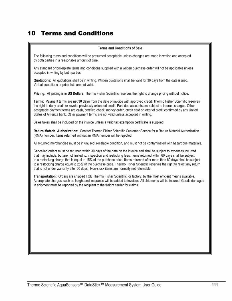
Thermo Scientific AquaSensors™ DataStick™ Measurement System User Guide 111
10 Terms and Conditions
Terms and Conditions of Sale The following terms and conditions will be presumed acceptable unless changes are made in writing and accepted by both parties in a reasonable amount of time. Any standard or boilerplate terms and conditions supplied with a written purchase order will not be applicable unless accepted in writing by both parties. Quotations: All quotations shall be in writing. Written quotations shall be valid for 30 days from the date issued. Verbal quotations or price lists are not valid. Pricing: All pricing is in US Dollars. Thermo Fisher Scientific reserves the right to change pricing without notice. Terms: Payment terms are net 30 days from the date of invoice with approved credit. Thermo Fisher Scientific reserves the right to deny credit or revoke previously extended credit. Past due accounts are subject to interest charges. Other acceptable payment terms are cash, certified check, money order, credit card or letter of credit confirmed by any United States of America bank. Other payment terms are not valid unless accepted in writing. Sales taxes shall be included on the invoice unless a valid tax exemption certificate is supplied. Return Material Authorization: Contact Thermo Fisher Scientific Customer Service for a Return Material Authorization (RMA) number. Items returned without an RMA number will be rejected. All returned merchandise must be in unused, resalable condition, and must not be contaminated with hazardous materials. Cancelled orders must be returned within 30 days of the date on the invoice and shall be subject to expenses incurred that may include, but are not limited to, inspection and restocking fees. Items returned within 60 days shall be subject to a restocking charge that is equal to 15% of the purchase price. Items returned after more than 60 days shall be subject to a restocking charge equal to 25% of the purchase price. Thermo Fisher Scientific reserves the right to reject any return that is not under warranty after 60 days. Non-stock items are normally not returnable. Transportation: Orders are shipped FOB Thermo Fisher Scientific, or factory, by the most efficient means available. Appropriate charges, such as freight and insurance will be added to invoices. All shipments will be insured. Goods damaged in shipment must be reported by the recipient to the freight carrier for claims.


258480-001 RevB 0510
9 0 0 1 : 2 0 0 8
Thermo Scientific
Environmental InstrumentsProcess Water Instruments
North America 166 Cummings Center Beverly, MA 01915 USA Toll Free: 1-800-225-1480 Tel: 1-978-232-6000 [email protected]
NetherlandsTel: (31) 033-2463887 [email protected]
IndiaTel: (91) 22-4175-8800 [email protected]
JapanTel: (81) 045-453-9175 [email protected]
ChinaTel: (86) 21-68654588 [email protected]
SingaporeTel: (65) 6778-6876 [email protected]
www.thermoscientific.com/water
© 2010 Thermo Fisher Scientific Inc. All rights reserved. All trademarks are the property of Thermo Fisher Scientific Inc. and its subsidiaries.