aquaculture facilities benefit from automated monitoring & control | ysi | webinar
TRANSCRIPT

How Aquaculture Facilities Benefit from Automation with YSI's Monitoring and
Control Instruments

Overview for Today
• M&C instruments • Expansion Modules • Control and monitoring applications • Feed smart feed timer • Sensor placement • Applications where used
- RAS, Aquaponics, Live Haul, Aquarium and Research

Models 5200A, 5400 and 5500D (M&C)
Multiparameter; DO, pH, Cond, Salinity, ORP (Redox), Temp. • 5200A-AC or DC
Multichannel (4) Galvanic DO • 5400-AC or DC
Multichannel (1 to 4) Optical DO • 5500D-01-AC or DC • 5500D-02-AC or DC • 5500D-04-AC or DC
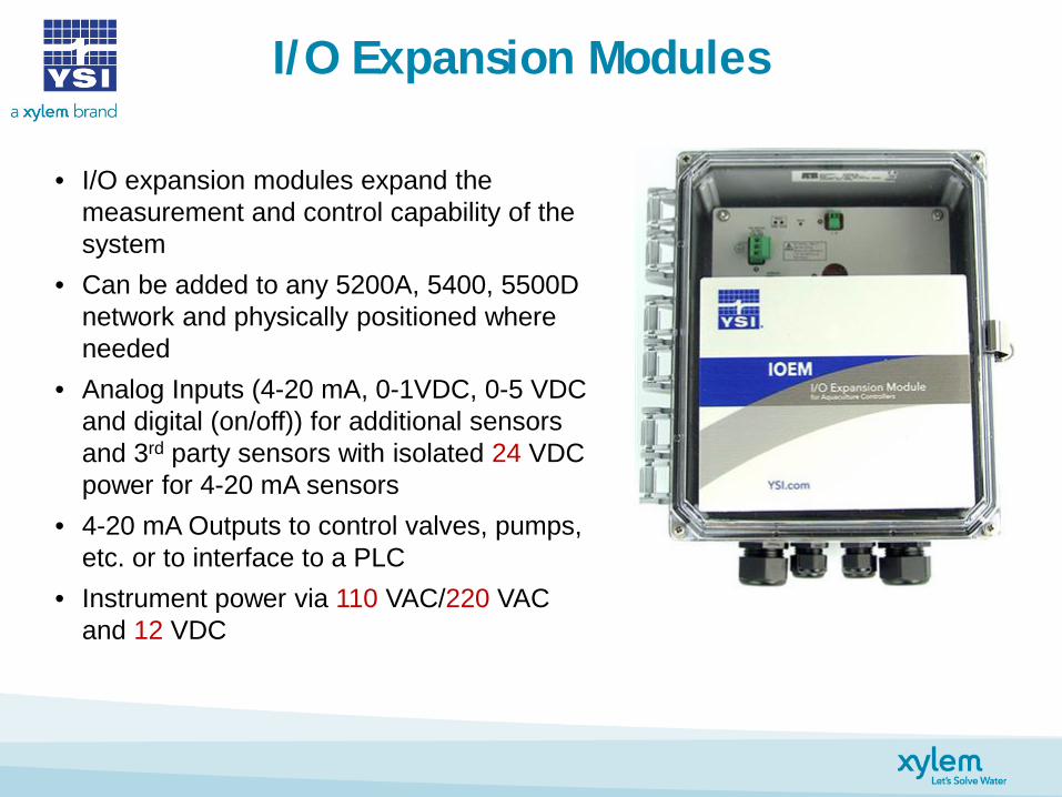
I/O Expansion Modules
• I/O expansion modules expand the measurement and control capability of the system
• Can be added to any 5200A, 5400, 5500D network and physically positioned where needed
• Analog Inputs (4-20 mA, 0-1VDC, 0-5 VDC and digital (on/off)) for additional sensors and 3rd party sensors with isolated 24 VDC power for 4-20 mA sensors
• 4-20 mA Outputs to control valves, pumps, etc. or to interface to a PLC
• Instrument power via 110 VAC/220 VAC and 12 VDC

REM Expansion Module
• REM expansion modules expand the control capability of the system with 4 additional dry contact relay’s
• Can be added to any 5200A, 5400, 5500D network and physically positioned where needed
• Each dry contact relay can be powered via 110 VAC/220 VAC or 12 VDC/24 VDC power with a common, normally open and normally closed connection to meet most required control needs
• Instrument power via 110 VAC/220 VAC and 12 VDC

Monitoring & Control

Monitoring & Control
YSI aquaculture instruments offer a variety of ways to automate your process:
- 4-20 mA output: scalable, analog, versatile
- Dry-contact relays: automated electrical switching, ideal for on-site alarms

Monitoring & Control
Analog output (4-20 mA) - Using a controller instrument and
an IOEM, you can output a proportional analog signal to a pump directly, or to a series of VFDs (variable frequency drives)
- With multiple VFDs, you have backup pumps in case you experience an equipment failure
YSI IOEM

Monitoring & Control
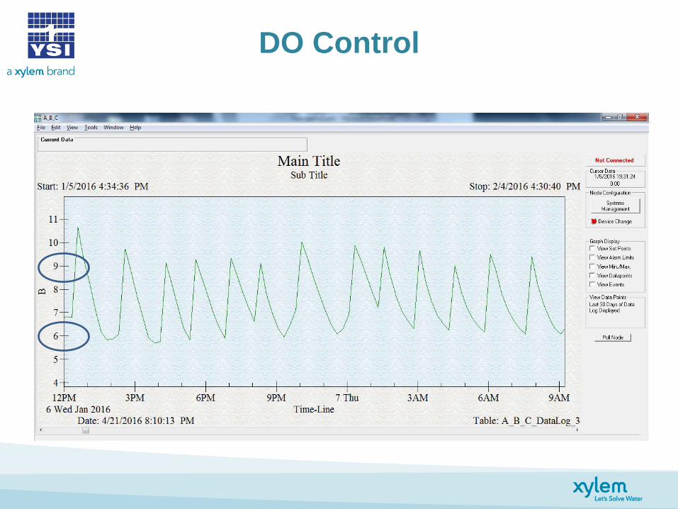
The 5500D continuously monitors DO concentration in the raceway.
YSI IOEM

Monitoring & Control
The IOEM module translates the output value for the DO to an analog signal.
YSI IOEM

Monitoring & Control
The VFDs interpret this analog signal and scale their output frequency as programmed.
YSI IOEM

Monitoring & Control
The pumps run at variable speeds depending on the signal that they receive from their corresponding VFDs.
YSI IOEM

Monitoring & Control
This same system also outputs a power consumption value that is continuously monitored and logged by the 5500D to notify staff of pump failures or excessive energy use.
YSI IOEM
Monitoring & Control
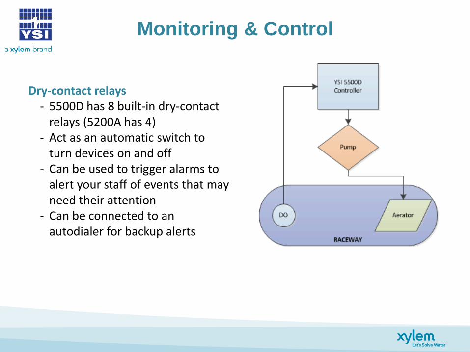
Dry-contact relays - 5500D has 8 built-in dry-contact
relays (5200A has 4) - Act as an automatic switch to
turn devices on and off - Can be used to trigger alarms to
alert your staff of events that may need their attention
- Can be connected to an autodialer for backup alerts

Monitoring & Control
The 5500D continuously monitors DO concentration in the tank.

Monitoring & Control
When a control condition is met, a relay is triggered in the 5500D (or an REM module if present)

Monitoring & Control
The relay, depending on how it is connected, can activate or
deactivate pumps, alarms, feeders, etc.

Monitoring & Control
The connected device will remain active and the 5500D will continue
to monitor.

Monitoring & Control
Once the DO is back in its user-specified range, the relay will switch again, deactivating the
pump.
Monitoring & Control
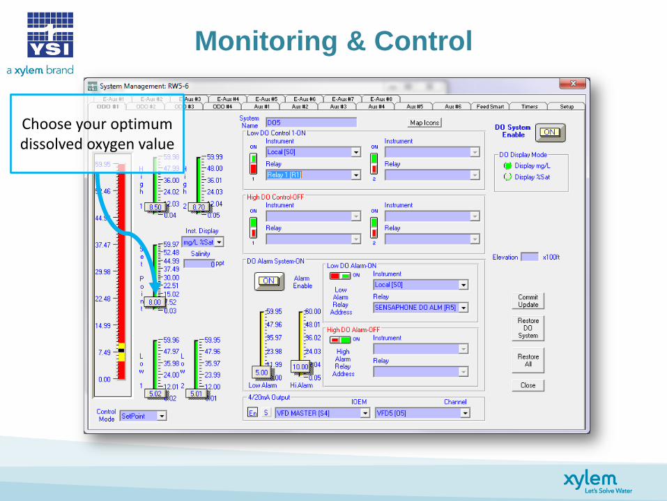
Choose your optimum dissolved oxygen value

Monitoring & Control
This value determines when a “Low DO”
condition is triggered

Monitoring & Control
This value determines when a “High DO” condition is triggered

Monitoring & Control
These values determine a secondary High or Low condition, for applications that demand a rapid response

Monitoring & Control
Determine when the High and Low alarms are triggered here

Monitoring & Control
Choose which relays to activate in the drop-down boxes for each condition
Monitoring & Control
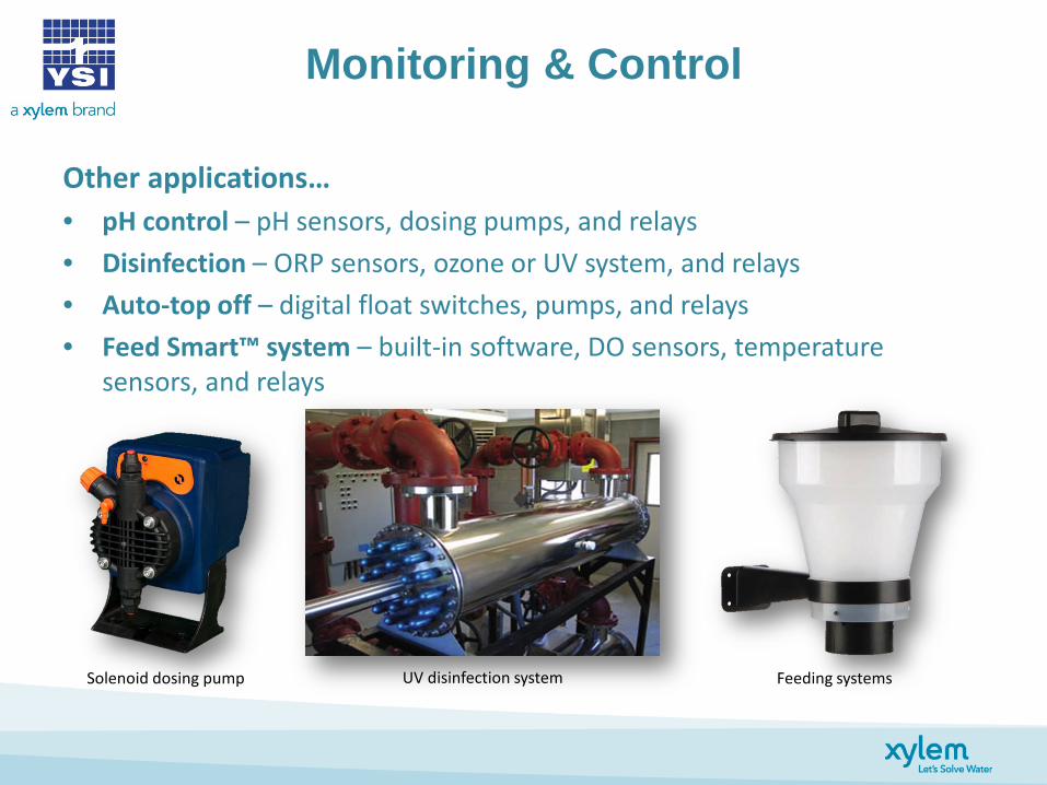
Other applications… • pH control – pH sensors, dosing pumps, and relays • Disinfection – ORP sensors, ozone or UV system, and relays • Auto-top off – digital float switches, pumps, and relays • Feed Smart™ system – built-in software, DO sensors, temperature
sensors, and relays
Solenoid dosing pump UV disinfection system Feeding systems

Feed Smart™ Feed Timer
• Standard in YSI 5200A, 5400 and 5500D continuous monitors
• 5200A controls one feed system while the 5400 and 5500D can control up to 4 separate feed systems
• Setup from monitor menu or from AquaManager™ desktop software
• Can be used with most powered feeders • Up to 255 feedings per day
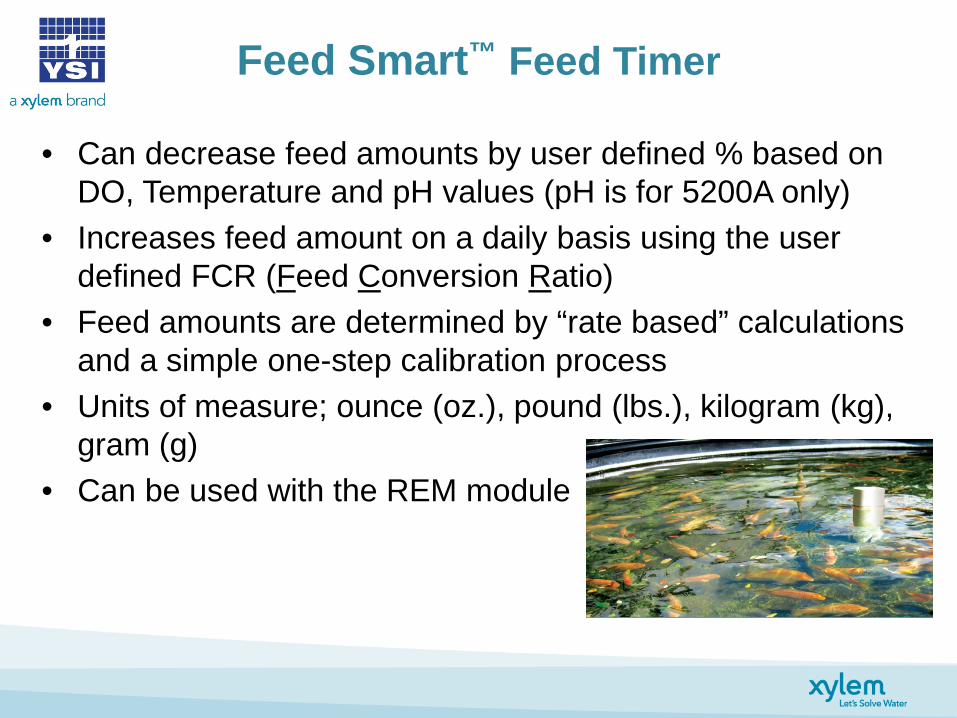
• Can decrease feed amounts by user defined % based on DO, Temperature and pH values (pH is for 5200A only)
• Increases feed amount on a daily basis using the user defined FCR (Feed Conversion Ratio)
• Feed amounts are determined by “rate based” calculations and a simple one-step calibration process
• Units of measure; ounce (oz.), pound (lbs.), kilogram (kg), gram (g)
• Can be used with the REM module
Feed Smart™ Feed Timer

• Continuous Mode
- takes the number of feedings per day and divides them equally within 24 hour for each day that you select to feed starting at midnight, i.e. feed 12 times per day will feed every two hours
• Timed Mode
- input a start and end time, the software then takes the total number of hours to feed and divides that by the number of feedings per day, i.e. start at 8:00am and end at 8:00pm and the fed 12 times a day then the feeders will turn on once an hour between 8:00am and 8:00pm
Setup on Feed Smart™

AquaManager Setup on Feed Smart™
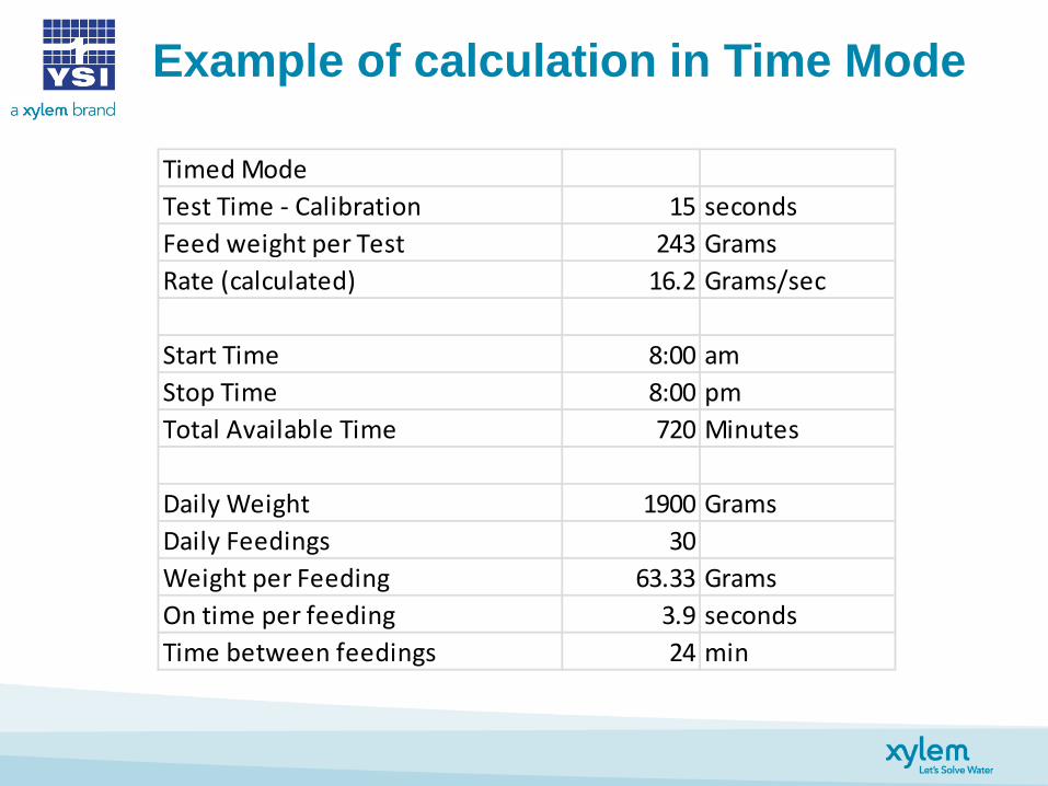
Example of calculation in Time Mode
Timed ModeTest Time - Calibration 15 secondsFeed weight per Test 243 GramsRate (calculated) 16.2 Grams/sec
Start Time 8:00 amStop Time 8:00 pmTotal Available Time 720 Minutes
Daily Weight 1900 GramsDaily Feedings 30Weight per Feeding 63.33 GramsOn time per feeding 3.9 secondsTime between feedings 24 min

Feeder and DO Control
• 7 tanks monitoring DO and Temp • Controlling DO and Feeders with 2 5500D monitors and 2 REM’s • Has 8 solenoids to control DO (1 for each tank and an emergency backup) controlled
by one 5500D and one REM • Has 7 feeders controlled by the second 5500D and REM using Feed Smart timer

DO Control Settings
DO Control

DO and Temperature Control

Blower and Temperature Control
Raceway 1
Raceway 2
Raceway 3
Raceway 4
Latching Switch
Primary Backup Blower Blower
DO/Temp sensors
Heater
Flow switch

Oxygen and Ozone Control LHO
Tank
DO/Temp sensor
Float switch
ORP sensor
O2 solenoid
O3 solenoid

DO Control at Tank and LHO
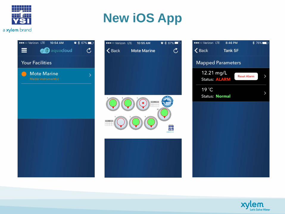
New iOS App

New iOS App

Best Location for Sensors
Sensor placement considerations: - Location of aeration equipment - Location of heating elements - Location of feeders - Flow of water/mixing - Minimum water depth
Make sure that your sensor cap stays wet. If it dries out, the paint layer can become brittle
and delaminated.

5500D Sensor Assembly
ODO sensor body
ODO sensor cap
Temperature sensor (on back)

5200A Sensor Assembly
DO sensor
DO sensor membrane cap
pH/ORP sensor
Conductivity/temperature sensor
Sensor bulkhead

pH or ORP Sensor
Standard selector ring
Sensor body
Replaceable pH or ORP electrode
Threaded for in-line installation

How to Contact YSI
Darrin Honious [email protected] (937) 767-7241 x246
Tyler Arnold [email protected] (937) 767-7241 x370
facebook.com/myYSI twitter.com/ysiinc linkedin.com/company/ysi youtube.com/ysiinc