apps.dtic.mil · afrl-rh-br-tr-2010-0046 . demonstration of a cylinder fill system based on solid...
TRANSCRIPT
AFRL-RH-BR-TR-2010-0046
DEMONSTRATION OF A CYLINDER FILL SYSTEM BASED ON SOLID ELECTROLYTE OXYGEN
SEPARATOR (SEOS) TECHNOLOGY: EARLY FIELD ASSESSMENT AT A USAF MAINTENANCE
FACILITY
David Studer
Air Products and Chemicals Inc.
7201 Hamilton Blvd. Allentown, PA 18195-1501
June 2010
Final Report for Sep 2008 – Jun 2010
Air Force Research Laboratory 711 Human Performance Wing Human Effectiveness Directorate Biosciences and Performance Division Biobehavior, Bioassessment & Biosurveillance Branch Brooks City-Base, TX 78235
Approved for public release; distribution unlimited, Public Affairs Case File No. 10-285
Approved for public release 10-285; distribution unlimited
NOTICE AND SIGNATURE PAGE
Using Government drawings, specifications, or other data included in this document for any purpose other than Government procurement does not in any way obligate the U.S. Government. The fact that the Government formulated or supplied the drawings, specifications, or other data does not license the holder or any other person or corporation; or convey any rights or permission to manufacture, use, or sell any patented invention that may relate to them. Qualified requestors may obtain copies of this report from the Defense Technical Information Center (DTIC) (http://www.dtic.mil). AFRL-RH-BR-TR-2010-0046 HAS BEEN REVIEWED AND IS APPROVED FOR PUBLICATION IN ACCORDANCE WITH ASSIGNED DISTRIBUTION STATEMENT.
______//SIGNED//____________________ __________//SIGNED//____________________ GEORGE MILLER MARK M. HOFFMAN Contract Monitor Deputy Division Chief Biobehavior, Bioassessment & Biosciences and Performance Division Biosurveillance Branch Human Effectiveness Directorate 711 Human Performance Wing
Air Force Research Laboratory
i Approved for public release 10-285; distribution unlimited
REPORT DOCUMENTATION PAGE Form Approved
OMB No. 0704-0188 Public reporting burden for this collection of information is estimated to average 1 hour per response, including the time for reviewing instructions, searching existing data sources, gathering and maintaining the data needed, and completing and reviewing this collection of information. Send comments regarding this burden estimate or any other aspect of this collection of information, including suggestions for reducing this burden to Department of Defense, Washington Headquarters Services, Directorate for Information Operations and Reports (0704-0188), 1215 Jefferson Davis Highway, Suite 1204, Arlington, VA 22202-4302. Respondents should be aware that notwithstanding any other provision of law, no person shall be subject to any penalty for failing to comply with a collection of information if it does not display a currently valid OMB control number. PLEASE DO NOT RETURN YOUR FORM TO THE ABOVE ADDRESS. 1. REPORT DATE (DD-MM-YYYY) 29-06-2010
2. REPORT TYPE Final Technical Report
3. DATES COVERED (From - To) 03 Sep 08 – 29 Jun 10
4. TITLE AND SUBTITLE Demonstration of a Cylinder Fill System Based on Solid Electrolyte Oxygen
5a. CONTRACT NUMBER FA8650-08-C-6824
Separator (SEOS) Technology: Early Field Assessment at a USAF Maintenance 5b. GRANT NUMBER
Facility
5c. PROGRAM ELEMENT NUMBER 62202F
6. AUTHOR(S) David Studer
5d. PROJECT NUMBER 7757
5e. TASK NUMBER P8
5f. WORK UNIT NUMBER 10
7. PERFORMING ORGANIZATION NAME(S) AND ADDRESS(ES)
8. PERFORMING ORGANIZATION REPORT NUMBER
Air Products and Chemicals Inc. 7201 Hamilton Blvd. Allentown PA 18195-1501
9. SPONSORING / MONITORING AGENCY NAME(S) AND ADDRESS(ES) 10. SPONSOR/MONITOR’S ACRONYM(S) Air Force Materiel Command Biobehavior, Bioassessment, and Biosurveillance Branch 711 HPW/RHP; 711 HPW/RHPF Air Force Research Laboratory 2485 Gillingham Dr 711 Human Performance Wing Brooks City-Base, TX 78235 11. SPONSOR/MONITOR’S REPORT Human Effectiveness Directorate NUMBER(S) Biosciences and Performance Division
AFRL-RH-BR-TR-2010-0046
12. DISTRIBUTION / AVAILABILITY STATEMENT Distribution A. Approved for public release; distribution unlimited.
13. SUPPLEMENTARY NOTES 14. ABSTRACT. The goal of the effort was to conduct an early field assessment of SEOS oxygen-generation technology. A SEOS breadboard for charging high pressure oxygen cylinders was installed in a maintenance facility at Oklahoma City-Air Logistics Center (OC-ALC), Tinker AFB OK. The SEOS breadboard was capable of generating 99.9+% oxygen at pressures up to 2,200 psig using electric power. The oxygen was stored in high pressure cylinders. The oxygen was tested per MIL-PRF-27210, Aviator's Breathing Oxygen (ABO), and it passed the ABO specification. The SEOS oxygen production unit worked well to fill aircraft oxygen bottles. On 20 Nov 09 the first aircraft oxygen bottle was filled with SEOS oxygen. During the effort several electrical problems on the compressor and ancillary electrical equipment were addressed. The SEOS electrochemical stacks used to generate the high purity oxygen functioned as expected. Tinker AFB operating personnel found the system very easy to use and it reduced safety risks associated with frequent change-out of vendor-supplied oxygen bottles. The early field assessment effort will be continued under USAF Contract F41624-00-C-6000.
15. SUBJECT TERMS Solid Electrolyte Oxygen Separator, SEOS, ceramic oxygen generating system, electrochemical cell, oxygen generation, field assessment, MIL-PRF-27210, Aviators’ Breathing Oxygen 16. SECURITY CLASSIFICATION OF: U
17. LIMITATION OF ABSTRACT
18. NUMBER OF PAGES
19a. NAME OF RESPONSIBLE PERSON George Miller
a. REPORT U
b. ABSTRACT U
c. THIS PAGE U
U 85 19b. TELEPHONE NUMBER (include area code)
Standard Form 298 (Rev. 8-98) Prescribed by ANSI Std. Z39.18

ii Approved for public release 10-285; distribution unlimited
This page left intentionally blank

iii Approved for public release 10-285; distribution unlimited
DISCLAIMER
This material is based upon work supported by the United States Air Force under Contract No. FA8650-08-C-6824. Any opinions, findings and conclusions or recommendations expressed in this material are those of the author and do not necessarily reflect the views of the United States Air Force. Neither Air Products and Chemicals, Inc. nor any of its contractors or subcontractors nor the United States Air Force, nor any person acting on behalf of either:
1. Makes any warranty or representation, express or implied, with respect to the accuracy, completeness, or usefulness of the information contained in this report, or that the use of any information, apparatus, method, or process disclosed in this report may not infringe privately owned rights; or
2. Assumes any liabilities with respect to the use of, or for damages resulting from the use of, any information, apparatus, method, or process disclosed in this report.
Reference herein to any specific commercial products, process, or service by trade name, trademark, manufacturer, or otherwise, does not necessarily constitute or imply its endorsement, recommendation, or favoring by the United States Air Force.
iv Approved for public release 10-285; distribution unlimited
TABLE OF CONTENTS
Section Page Executive Summary 1 1.0 Introduction and Background 1 1.1 Introduction 1 1.2 Background 2 2.0 Discussion of Results 3 2.1 Design 3 2.2 Equipment Modifications 4 2.3 Installation 4 2.4 Start-up 4 2.5 Operation and Maintenance 6 3.0 Conclusions and Recommendations 7 4.0 APPENDIX A – SEOS Technical Background Information APPENDIX B – Operating Manual APPENDIX C – Narrative Logbook APPENDIX D – Laboratory Oxygen Analysis Reports APPENDIX E – Questionnaire Figures: Figure 1. "Exploded" view of a SEOS oxygen-generating couplet 2 Figure 2. View of an ITM SEOS Stack 3 Figure 3. Simplified schematic of six (6) SLPM cylinder fill breadboard. 4 Photographs: Photograph #1. SEOS breadboard installed at OC-ALC maintenance facility. 5 Photograph #2. SEOS breadboard shown with OC-ALC high pressure oxygen supply system. 6
1 Approved for public release 10-285; distribution unlimited
Executive Summary The goal of the effort was to conduct an early field assessment of SEOS oxygen-generation technology and obtain user feedback and lessons learned. A SEOS breadboard for charging high pressure oxygen cylinders was installed at a maintenance facility at Oklahoma City-Air Logistics Center (OC-ALC), Tinker AFB OK. OC-ALC, Air Products and Chemicals, Inc., Ceramatec Inc., and the Air Force Research Laboratory (AFRL) worked collaboratively on this effort. Tinker AFB modified the facility to allow integration of the SEOS breadboard into its existing high pressure oxygen system. The SEOS breadboard was capable of producing 99.9+% oxygen at pressures up to 2,200 psig. The oxygen was stored in high pressure cylinders and was used to fill aircraft oxygen bottles. The oxygen was tested several times per MIL-PRF-27210, Aviator's Breathing Oxygen (ABO), and it passed the ABO specification. On 20 November 09 the first aircraft oxygen bottle was filled with SEOS oxygen. During the effort several electrical problems on the compressor and ancillary electrical equipment were addressed. The SEOS electrochemical stacks used to generate the high purity oxygen appeared to function as expected. The program goal was to operate the breadboard for one (1) year at the user site. This report documents the first six (6) months of the early field assessment period. The effort will be continued for an additional six (6) months under USAF R&D Contract F41624-00-C-6000. The SEOS oxygen production unit worked well to fill aircraft oxygen bottles. The system successfully delivered oxygen at a flow rate, purity, and pressure meeting ABO requirements, and the Tinker AFB operating personnel found the system very easy to use. However, there were operating issues with some of the auxiliary equipment, which should be addressed in future units. 1.0 Introduction and Background 1.1 Introduction This effort assessed the “real-life” performance of an advanced breadboard comprising oxygen-generation and cylinder-fill compression equipment developed under a research contract between Air Products and AFRL. The oxygen generation is accomplished using a planar ceramic, electrolytic membrane consisting of an advanced electrolyte. User feedback provided valuable information on the performance of the system and the technology, and will be beneficial in directing future development of this advanced oxygen-generation technology. A six (6) standard liter per minute Advanced SEOS Breadboard (previously built and demonstrated to the Air Force under R&D contract F41624-00-C-6000) was modified and installed on a mobile cart with oxygen compression equipment. This breadboard was then integrated into the existing high pressure oxygen system at a maintenance facility at Tinker AFB OK. An important element of the integration was that the breadboard could be easily disconnected and replaced by a vendor supplied high pressure oxygen cylinder, if the breadboard malfunctioned.
2 Approved for public release 10-285; distribution unlimited
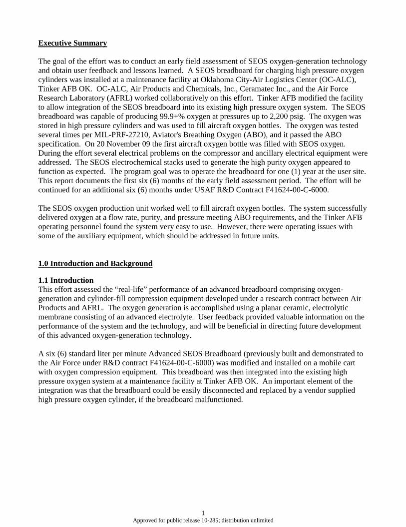
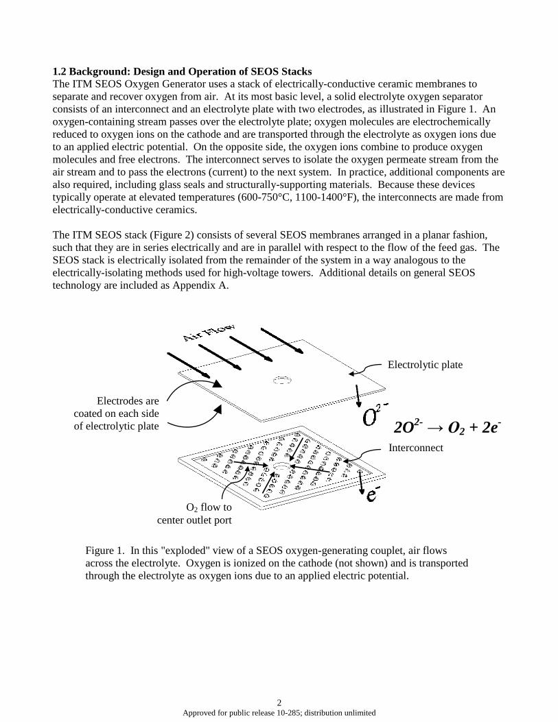
1.2 Background: Design and Operation of SEOS Stacks The ITM SEOS Oxygen Generator uses a stack of electrically-conductive ceramic membranes to separate and recover oxygen from air. At its most basic level, a solid electrolyte oxygen separator consists of an interconnect and an electrolyte plate with two electrodes, as illustrated in Figure 1. An oxygen-containing stream passes over the electrolyte plate; oxygen molecules are electrochemically reduced to oxygen ions on the cathode and are transported through the electrolyte as oxygen ions due to an applied electric potential. On the opposite side, the oxygen ions combine to produce oxygen molecules and free electrons. The interconnect serves to isolate the oxygen permeate stream from the air stream and to pass the electrons (current) to the next system. In practice, additional components are also required, including glass seals and structurally-supporting materials. Because these devices typically operate at elevated temperatures (600-750°C, 1100-1400°F), the interconnects are made from electrically-conductive ceramics. The ITM SEOS stack (Figure 2) consists of several SEOS membranes arranged in a planar fashion, such that they are in series electrically and are in parallel with respect to the flow of the feed gas. The SEOS stack is electrically isolated from the remainder of the system in a way analogous to the electrically-isolating methods used for high-voltage towers. Additional details on general SEOS technology are included as Appendix A.
Figure 1. In this "exploded" view of a SEOS oxygen-generating couplet, air flows across the electrolyte. Oxygen is ionized on the cathode (not shown) and is transported through the electrolyte as oxygen ions due to an applied electric potential.
Electrolytic plate
Interconnect
O2 flow to center outlet port
Electrodes are coated on each side of electrolytic plate 2O2- → O2 + 2e-
3 Approved for public release 10-285; distribution unlimited
Figure 2. In this "exploded" view of an ITM SEOS stack, air flows in parallel through channels in the stack face and across the electrolyte. The oxygen product is isolated by a seal between the rim of the interconnecting plate and the electrolyte, collected in the central manifold, and exits from the stack through the centrally-positioned oxygen piping.
2.0 Discussion of Results 2.1 Design Prior to beginning the effort, a SEOS breadboard oxygen sample was collected and analyzed at a Wright-Patterson AFB laboratory to ensure SEOS oxygen conformed to MIL-PRF-27210G, Aviators’ Breathing Oxygen. The results exceeded the military specification purity requirements. The analysis results are included in Appendix D. Tinker AFB accomplished modifications to its facility to allow the integration of the SEOS breadboard into the facility’s high pressure oxygen system. Tinker AFB also provided a piping and instrumentation drawing showing the modifications. Air Products was permitted to review the drawings. Site modifications also included a new 30A/120V AC electrical service for the SEOS unit. Air Products conducted a Hazard Analysis of the modified breadboard. The methodology identified and analyzed potential safety hazards and defined safeguards to mitigate or minimize the risk level. All of the corrective actions identified in the hazard review, including materials changes, relief scenario evaluations, back flow prevention, secondary containment and documentation updates, were completed prior to operation of the unit.
Depleted Air Non-Permeate
4 Approved for public release 10-285; distribution unlimited
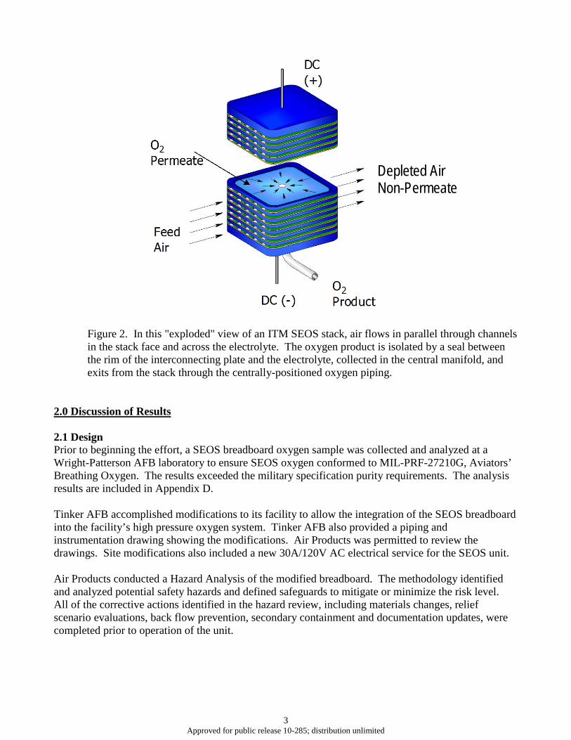
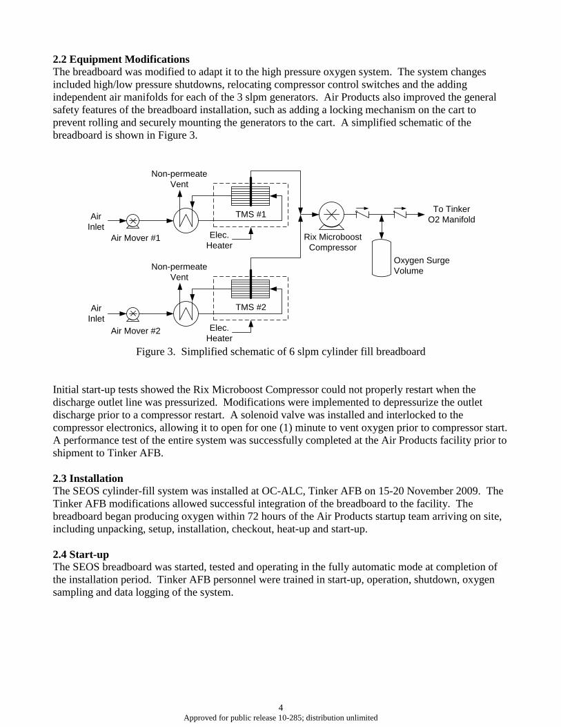
2.2 Equipment Modifications The breadboard was modified to adapt it to the high pressure oxygen system. The system changes included high/low pressure shutdowns, relocating compressor control switches and the adding independent air manifolds for each of the 3 slpm generators. Air Products also improved the general safety features of the breadboard installation, such as adding a locking mechanism on the cart to prevent rolling and securely mounting the generators to the cart. A simplified schematic of the breadboard is shown in Figure 3.
Figure 3. Simplified schematic of 6 slpm cylinder fill breadboard
Initial start-up tests showed the Rix Microboost Compressor could not properly restart when the discharge outlet line was pressurized. Modifications were implemented to depressurize the outlet discharge prior to a compressor restart. A solenoid valve was installed and interlocked to the compressor electronics, allowing it to open for one (1) minute to vent oxygen prior to compressor start. A performance test of the entire system was successfully completed at the Air Products facility prior to shipment to Tinker AFB. 2.3 Installation The SEOS cylinder-fill system was installed at OC-ALC, Tinker AFB on 15-20 November 2009. The Tinker AFB modifications allowed successful integration of the breadboard to the facility. The breadboard began producing oxygen within 72 hours of the Air Products startup team arriving on site, including unpacking, setup, installation, checkout, heat-up and start-up. 2.4 Start-up The SEOS breadboard was started, tested and operating in the fully automatic mode at completion of the installation period. Tinker AFB personnel were trained in start-up, operation, shutdown, oxygen sampling and data logging of the system.
Air Inlet
Air Inlet
Air Mover #1
Air Mover #2
TMS #1
TMS #2
Elec. Heater
Elec. Heater
Rix Microboost Compressor
Oxygen Surge Volume
To Tinker O2 Manifold
Non-permeate Vent
Non-permeate Vent

5 Approved for public release 10-285; distribution unlimited
On 20 November 2009 Tinker personnel took two oxygen samples and submitted them to the Tinker AFB laboratory for analysis. The Tinker AFB laboratory confirmed that the oxygen samples met MIL-PRF-27210G, Aviators’ Breathing Oxygen. In general, oxygen samples were collected and analyzed every forty-five (45) days. Pictures below show the SEOS breadboard at Tinker AFB.
Photograph #1. SEOS breadboard installed at OC-ALC maintenance facility.
6 Approved for public release 10-285; distribution unlimited
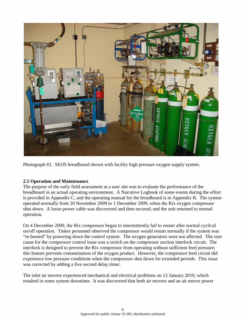
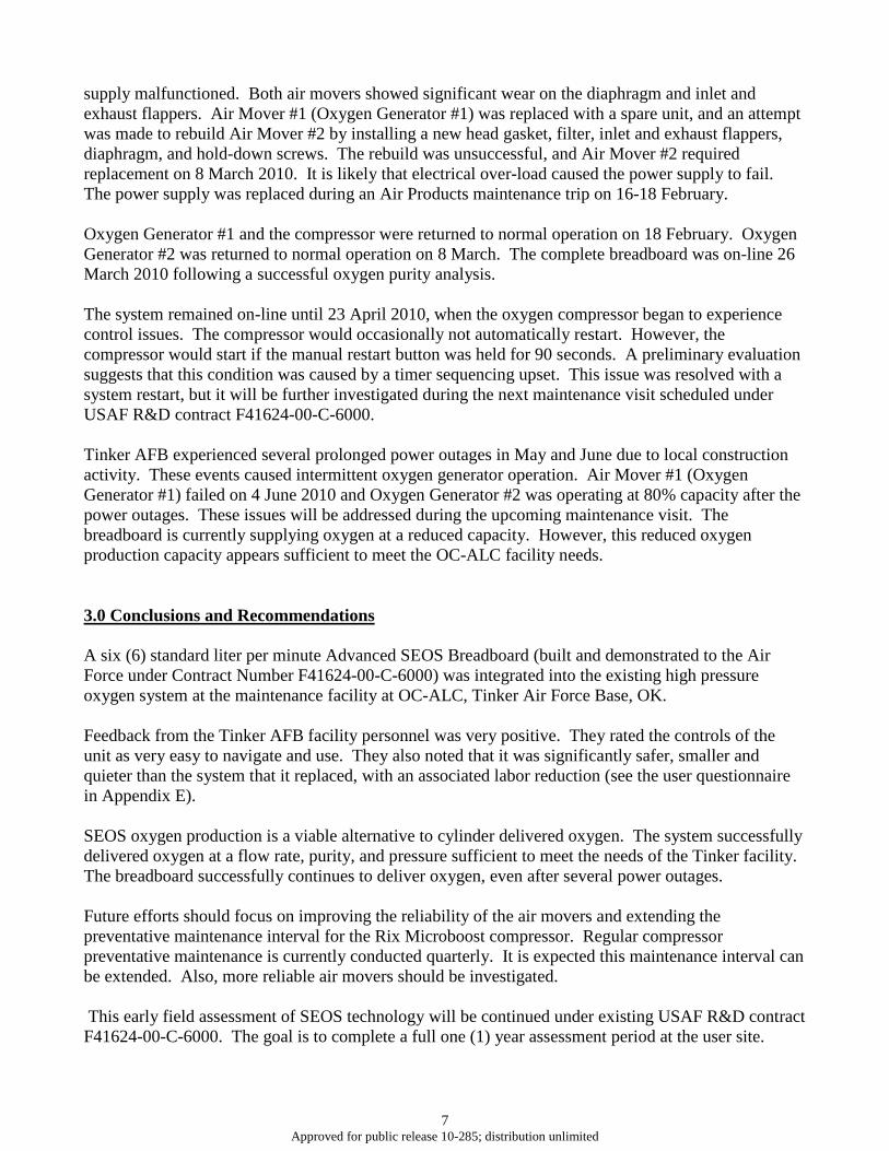
Photograph #2. SEOS breadboard shown with facility high pressure oxygen supply system. 2.5 Operation and Maintenance The purpose of the early field assessment at a user site was to evaluate the performance of the breadboard in an actual operating environment. A Narrative Logbook of some events during the effort is provided in Appendix C, and the operating manual for the breadboard is in Appendix B. The system operated normally from 20 November 2009 to 1 December 2009, when the Rix oxygen compressor shut down. A loose power cable was discovered and then secured; and the unit returned to normal operation. On 4 December 2009, the Rix compressor began to intermittently fail to restart after normal cyclical on/off operation. Tinker personnel observed the compressor would restart normally if the system was “re-booted” by powering down the control system. The oxygen generators were not affected. The root cause for the compressor control issue was a switch on the compressor suction interlock circuit. The interlock is designed to prevent the Rix compressor from operating without sufficient feed pressure; this feature prevents contamination of the oxygen product. However, the compressor feed circuit did experience low pressure conditions when the compressor shut down for extended periods. This issue was corrected by adding a five second delay timer. The inlet air movers experienced mechanical and electrical problems on 13 January 2010, which resulted in some system downtime. It was discovered that both air movers and an air mover power
7 Approved for public release 10-285; distribution unlimited
supply malfunctioned. Both air movers showed significant wear on the diaphragm and inlet and exhaust flappers. Air Mover #1 (Oxygen Generator #1) was replaced with a spare unit, and an attempt was made to rebuild Air Mover #2 by installing a new head gasket, filter, inlet and exhaust flappers, diaphragm, and hold-down screws. The rebuild was unsuccessful, and Air Mover #2 required replacement on 8 March 2010. It is likely that electrical over-load caused the power supply to fail. The power supply was replaced during an Air Products maintenance trip on 16-18 February. Oxygen Generator #1 and the compressor were returned to normal operation on 18 February. Oxygen Generator #2 was returned to normal operation on 8 March. The complete breadboard was on-line 26 March 2010 following a successful oxygen purity analysis. The system remained on-line until 23 April 2010, when the oxygen compressor began to experience control issues. The compressor would occasionally not automatically restart. However, the compressor would start if the manual restart button was held for 90 seconds. A preliminary evaluation suggests that this condition was caused by a timer sequencing upset. This issue was resolved with a system restart, but it will be further investigated during the next maintenance visit scheduled under USAF R&D contract F41624-00-C-6000. Tinker AFB experienced several prolonged power outages in May and June due to local construction activity. These events caused intermittent oxygen generator operation. Air Mover #1 (Oxygen Generator #1) failed on 4 June 2010 and Oxygen Generator #2 was operating at 80% capacity after the power outages. These issues will be addressed during the upcoming maintenance visit. The breadboard is currently supplying oxygen at a reduced capacity. However, this reduced oxygen production capacity appears sufficient to meet the OC-ALC facility needs. 3.0 Conclusions and Recommendations A six (6) standard liter per minute Advanced SEOS Breadboard (built and demonstrated to the Air Force under Contract Number F41624-00-C-6000) was integrated into the existing high pressure oxygen system at the maintenance facility at OC-ALC, Tinker Air Force Base, OK. Feedback from the Tinker AFB facility personnel was very positive. They rated the controls of the unit as very easy to navigate and use. They also noted that it was significantly safer, smaller and quieter than the system that it replaced, with an associated labor reduction (see the user questionnaire in Appendix E). SEOS oxygen production is a viable alternative to cylinder delivered oxygen. The system successfully delivered oxygen at a flow rate, purity, and pressure sufficient to meet the needs of the Tinker facility. The breadboard successfully continues to deliver oxygen, even after several power outages. Future efforts should focus on improving the reliability of the air movers and extending the preventative maintenance interval for the Rix Microboost compressor. Regular compressor preventative maintenance is currently conducted quarterly. It is expected this maintenance interval can be extended. Also, more reliable air movers should be investigated. This early field assessment of SEOS technology will be continued under existing USAF R&D contract F41624-00-C-6000. The goal is to complete a full one (1) year assessment period at the user site.

APPENDIX A – SEOS Technical Background Information
8 Approved for public release 10-285; distribution unlimited
OXYGEN GENERATION USING SEOS ION TRANSPORT MEMBRANES
Joseph M. Abrardo
E. P. Ted Foster
Brian M. O’Neil
Air Products and Chemicals, Inc.
7201 Hamilton Boulevard
Allentown, PA 18195
Air Products and Chemicals, Inc., 2001
INTRODUCTION
Oxygen is used by the military in medical, breathing, and metal fabrication and cutting applications.
Historically, this oxygen has been supplied as high purity, compressed gas in cylinders or bottles and
as liquid in dewars. The distribution and handling requirements for these products necessitate a
significant logistics infrastructure and associated cost. Point-of-use oxygen generation nearly
eliminates the required logistics infrastructure and, for this reason, oxygen generators, based on
adsorption technology, have made significant in-roads in oxygen supply for the military. Uses of these
generators, however, have been limited to applications that will tolerate the lower oxygen purity
provided by such systems. Applications, which demand high purity oxygen, have no alternative to
distributed oxygen and its associated logistics infrastructure requirements. A new technology,
employing ion transport membranes (ITM), has the potential to provide many of these applications
with point-of-use generation of high purity oxygen 1.
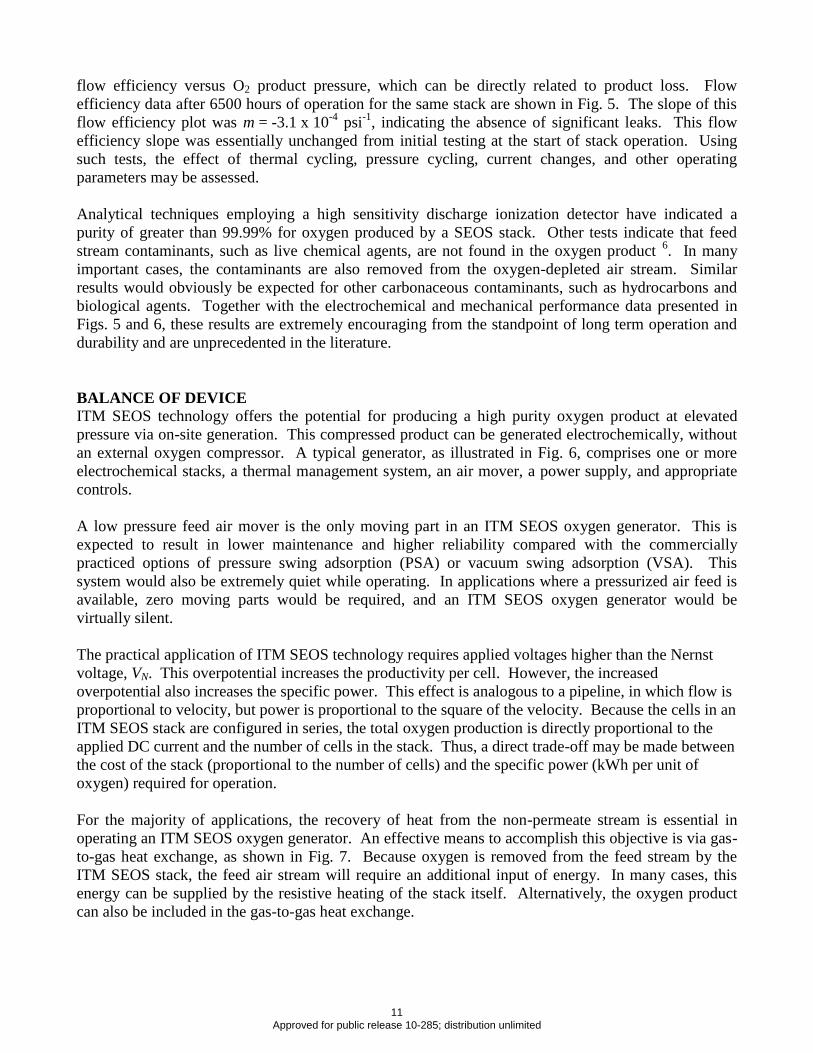
The ITM solid electrolyte oxygen separation (SEOS) technology is based on the principle of oxygen
ion migration through a dense ceramic electrolyte membrane under the influence of an externally
applied electrical potential, as illustrated in Fig. 1. The relationship between the equilibrium oxygen
partial pressures on the anode and cathode side of the electrolyte is governed by the Nernst equation:
)ln(4 ,
,
2
2
cathodeO
anodeO
Np
p
F
RTV (1)
Removal of the oxygen product from the anode side of the electrolyte membrane results in the
continuous production of pure oxygen. The ITM SEOS process enables the production of high purity
oxygen at elevated pressure from a feed stream of ambient pressure air.
STACK MATERIALS
The core of ITM SEOS technology is an electrochemical stack fabricated from high-temperature
conductive ceramic materials 2. The solid electrolyte is based on cerium oxide, with dopants added to
enhance both ion transport and membrane processability. To achieve sufficient oxygen ion
conductivity through the electrolyte, the device must be operated at a temperature above approximately
600 C. At these temperatures, doped ceria exhibits a significant performance advantage over
9 Approved for public release 10-285; distribution unlimited
zirconia-based materials. For example, the conductivity of Gd-doped ceria at 800 C is about 0.1
S/cm, and is approximately one order of magnitude higher than that of YSZ 3. The doped ceria
electrolyte is combined with appropriate electrode materials to form an electrochemical cell. The
electrode materials must be chosen to minimize or eliminate electrolyte-electrode interfacial
resistances, to exhibit high ionic and electronic conductivity, and to be catalytically active for the
electrochemical reduction and oxidation reactions. An SEM image of a porous electrode layer over the
dense ceria-based electrolyte is shown in Fig. 2. Electrochemical test data have established cell
performance over thousands of hours and have enabled optimization of electrolyte and electrode
characteristics.
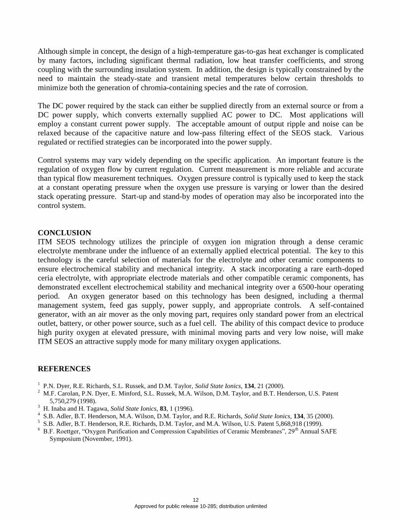
The principle of electrically driven ion migration provides the mechanistic basis for ITM SEOS
technology. However, a device comprising several cells, in series or in parallel, is required for
commercial use. An efficient means for accomplishing this goal involves a flat plate multi-cell stack.
Each cell, comprising a dense electrolyte coated with porous anode and cathode layers, is in contact
with a dense interconnect made from an electronically conductive perovskite material. A 32-cell ITM
SEOS stack is shown in Fig. 3.
Each interconnect is featured to provide appropriate passages for the feed and product streams. In
contrast to the electrolyte, the interconnect must be an ionic insulator and an electronic conductor.
Because the interconnects provide the mechanical backbone of the planar ITM SEOS device, the
materials used must provide the required strength, stability, degradation, and other properties and must
be compatible with the electrolyte and electrode materials.
The repeat units of the ITM SEOS stack, connected electrically in series, also include biasing
electrodes and offset glass-ceramic seals to maintain seal integrity under operating conditions. These
measures are necessary to avoid delamination at the interface between the glass-ceramic sealant and
the anode side of the doped ceria electrolyte during operation 4,5
. In addition, all stack materials must
be carefully selected to meet criteria for thermal expansion match, chemical compatibility, and
mechanical robustness, as well as for ionic and electronic conductivity.
STACK PERFORMANCE
The two primary considerations for long term ITM SEOS stack operation are electrochemical
performance and mechanical integrity. Electrochemical performance is characterized by the stack
Area Specific Resistance (ASR) under operating conditions. Fig. 4 illustrates the electrochemical
performance for a 3-cell test stack over more than 6500 hours. A relatively stable ASR of
approximately 0.6 cm2 is evident.
The mechanical integrity of the operating stack as a function of time was measured using flow
efficiency measurements. These measurements are based on the general relationship between
electrical current and oxygen produced in a multi-cell ITM SEOS stack. The flow efficiency is defined
as the ratio of actual O2 product flowrate to theoretical product flowrate.
In a flow efficiency experiment designed to detect leaks, the product O2 pressure is raised
incrementally to a test level of 5-10 psig. If a leak is present in the stack, the flow efficiency will
decrease as some O2 product is forced through the leak. The data may be characterized by the slope of
10 Approved for public release 10-285; distribution unlimited
flow efficiency versus O2 product pressure, which can be directly related to product loss. Flow
efficiency data after 6500 hours of operation for the same stack are shown in Fig. 5. The slope of this
flow efficiency plot was m = -3.1 x 10⁻⁴
psi-1
, indicating the absence of significant leaks. This flow
efficiency slope was essentially unchanged from initial testing at the start of stack operation. Using
such tests, the effect of thermal cycling, pressure cycling, current changes, and other operating
parameters may be assessed.
Analytical techniques employing a high sensitivity discharge ionization detector have indicated a
purity of greater than 99.99% for oxygen produced by a SEOS stack. Other tests indicate that feed
stream contaminants, such as live chemical agents, are not found in the oxygen product 6. In many
important cases, the contaminants are also removed from the oxygen-depleted air stream. Similar
results would obviously be expected for other carbonaceous contaminants, such as hydrocarbons and
biological agents. Together with the electrochemical and mechanical performance data presented in
Figs. 5 and 6, these results are extremely encouraging from the standpoint of long term operation and
durability and are unprecedented in the literature.
BALANCE OF DEVICE
ITM SEOS technology offers the potential for producing a high purity oxygen product at elevated
pressure via on-site generation. This compressed product can be generated electrochemically, without
an external oxygen compressor. A typical generator, as illustrated in Fig. 6, comprises one or more
electrochemical stacks, a thermal management system, an air mover, a power supply, and appropriate
controls.
A low pressure feed air mover is the only moving part in an ITM SEOS oxygen generator. This is
expected to result in lower maintenance and higher reliability compared with the commercially
practiced options of pressure swing adsorption (PSA) or vacuum swing adsorption (VSA). This
system would also be extremely quiet while operating. In applications where a pressurized air feed is
available, zero moving parts would be required, and an ITM SEOS oxygen generator would be
virtually silent.
The practical application of ITM SEOS technology requires applied voltages higher than the Nernst
voltage, VN. This overpotential increases the productivity per cell. However, the increased
overpotential also increases the specific power. This effect is analogous to a pipeline, in which flow is
proportional to velocity, but power is proportional to the square of the velocity. Because the cells in an
ITM SEOS stack are configured in series, the total oxygen production is directly proportional to the
applied DC current and the number of cells in the stack. Thus, a direct trade-off may be made between
the cost of the stack (proportional to the number of cells) and the specific power (kWh per unit of
oxygen) required for operation.
For the majority of applications, the recovery of heat from the non-permeate stream is essential in
operating an ITM SEOS oxygen generator. An effective means to accomplish this objective is via gas-
to-gas heat exchange, as shown in Fig. 7. Because oxygen is removed from the feed stream by the
ITM SEOS stack, the feed air stream will require an additional input of energy. In many cases, this
energy can be supplied by the resistive heating of the stack itself. Alternatively, the oxygen product
can also be included in the gas-to-gas heat exchange.
11 Approved for public release 10-285; distribution unlimited
Although simple in concept, the design of a high-temperature gas-to-gas heat exchanger is complicated
by many factors, including significant thermal radiation, low heat transfer coefficients, and strong
coupling with the surrounding insulation system. In addition, the design is typically constrained by the
need to maintain the steady-state and transient metal temperatures below certain thresholds to
minimize both the generation of chromia-containing species and the rate of corrosion.
The DC power required by the stack can either be supplied directly from an external source or from a
DC power supply, which converts externally supplied AC power to DC. Most applications will
employ a constant current power supply. The acceptable amount of output ripple and noise can be
relaxed because of the capacitive nature and low-pass filtering effect of the SEOS stack. Various
regulated or rectified strategies can be incorporated into the power supply.
Control systems may vary widely depending on the specific application. An important feature is the
regulation of oxygen flow by current regulation. Current measurement is more reliable and accurate
than typical flow measurement techniques. Oxygen pressure control is typically used to keep the stack
at a constant operating pressure when the oxygen use pressure is varying or lower than the desired
stack operating pressure. Start-up and stand-by modes of operation may also be incorporated into the
control system.
CONCLUSION
ITM SEOS technology utilizes the principle of oxygen ion migration through a dense ceramic
electrolyte membrane under the influence of an externally applied electrical potential. The key to this
technology is the careful selection of materials for the electrolyte and other ceramic components to
ensure electrochemical stability and mechanical integrity. A stack incorporating a rare earth-doped
ceria electrolyte, with appropriate electrode materials and other compatible ceramic components, has
demonstrated excellent electrochemical stability and mechanical integrity over a 6500-hour operating
period. An oxygen generator based on this technology has been designed, including a thermal
management system, feed gas supply, power supply, and appropriate controls. A self-contained
generator, with an air mover as the only moving part, requires only standard power from an electrical
outlet, battery, or other power source, such as a fuel cell. The ability of this compact device to produce
high purity oxygen at elevated pressure, with minimal moving parts and very low noise, will make
ITM SEOS an attractive supply mode for many military oxygen applications.
REFERENCES
1 P.N. Dyer, R.E. Richards, S.L. Russek, and D.M. Taylor, Solid State Ionics, 134, 21 (2000).
2 M.F. Carolan, P.N. Dyer, E. Minford, S.L. Russek, M.A. Wilson, D.M. Taylor, and B.T. Henderson, U.S. Patent
5,750,279 (1998). 3 H. Inaba and H. Tagawa, Solid State Ionics, 83, 1 (1996).
4 S.B. Adler, B.T. Henderson, M.A. Wilson, D.M. Taylor, and R.E. Richards, Solid State Ionics, 134, 35 (2000).
5 S.B. Adler, B.T. Henderson, R.E. Richards, D.M. Taylor, and M.A. Wilson, U.S. Patent 5,868,918 (1999).
6 B.F. Roettger, “Oxygen Purification and Compression Capabilities of Ceramic Membranes”, 29
th Annual SAFE
Symposium (November, 1991).
12 Approved for public release 10-285; distribution unlimited
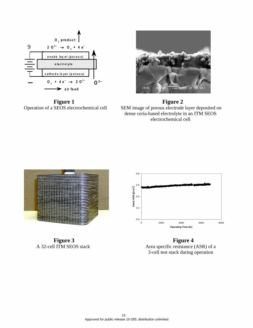
Figure 1 Figure 2 Operation of a SEOS electrochemical cell SEM image of porous electrode layer deposited on
dense ceria-based electrolyte in an ITM SEOS
electrochemical cell
Figure 3 Figure 4 A 32-cell ITM SEOS stack Area specific resistance (ASR) of a
3-cell test stack during operation
a ir fe e d
O2
p ro d u c t
9
— O 2
c a t h o d e la y e r ( p o r o u s )
a n o d e la y e r ( p o r o u s )
e le c t r o l y t e
O2
+ 4 e 2 O
2
2 O2
O2
+ 4 e
0.0
0.2
0.4
0.6
0.8
0 2000 4000 6000 8000
Operating Time (hr)
Stac
k A
SR (
. cm2 )
13 Approved for public release 10-285; distribution unlimited
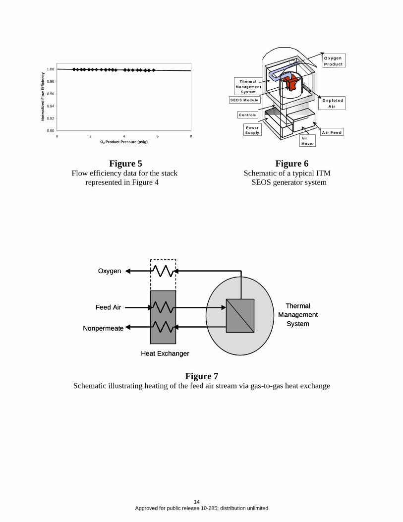
Figure 5 Figure 6 Flow efficiency data for the stack Schematic of a typical ITM
represented in Figure 4 SEOS generator system
Figure 7 Schematic illustrating heating of the feed air stream via gas-to-gas heat exchange
0.90
0.92
0.94
0.96
0.98
1.00
0 2 4 6 8O2 Product Pressure (psig)
Nor
mal
ized
Flo
w E
ffic
ienc
y
O xygen Pr odu ct
A ir Fee d
D epletedA ir
T h erm al M an ag emen t
Sys tem
S EO S M od u le
Po w erS up p ly
C on tr ols
Air M o ver
Feed Air
Nonpermeate
Oxygen
Heat Exchanger
Thermal Management
System
Feed Air
Nonpermeate
Oxygen
Heat Exchanger
Thermal Management
System
14 Approved for public release 10-285; distribution unlimited

APPENDIX B – Operating Manual
15 Approved for public release 10-285; distribution unlimited
DEMONSTRATION OF A CYLINDER-FILL SYSTEM
BASED ON SOLID ELECTROLYTE OXYGEN SEPARATOR
(SEOS) TECHNOLOGY
FA8650-08-2-6824
Checklists and Operating Manuals
(CDRL A003)
September, 2009
Air Products and Chemicals, Inc.
7201 Hamilton Blvd.
Allentown, PA 18195
16 Approved for public release 10-285; distribution unlimited
TABLE OF CONTENTS
Page
Prestart Checklist………………………………………………………………………………….2
Oxygen Generator Start-up Checklist……………………………………………………….........7
Rix Oxygen Compressor Startup Checklist……………………………………………………...10
Oxygen Surge Cylinders Sampling Checklist……………………………………………………12
Emergency Shutdown Procedure………………………………………………………………...14
6 LPM Fill Cylinder Advanced Breadboard System Schematic………………………………...16
Oxygen Sampling Manifold Schematic………………………………………………………….17
Appendix 1 Oxygen Generator Operating Manual.……………………………………………...18
Appendix 2 Rix Compressor Automatic Shutdown Guide………………………………………28
Page 1
17 Approved for public release 10-285; distribution unlimited
6LPM Advanced Breadboard Pre-startup Checklist
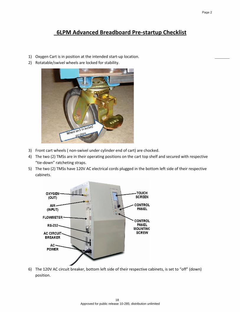
1) Oxygen Cart is in position at the intended start-up location.
2) Rotatable/swivel wheels are locked for stability.
3) Front cart wheels ( non-swivel under cylinder end of cart) are chocked.
4) The two (2) TMSs are in their operating positions on the cart top shelf and secured with respective
“tie-down” ratcheting straps.
5) The two (2) TMSs have 120V AC electrical cords plugged in the bottom left side of their respective
cabinets.
6) The 120V AC circuit breaker, bottom left side of their respective cabinets, is set to “off” (down)
position.
Page 2
18 Approved for public release 10-285; distribution unlimited

7) The oxygen outlet lines, one line per TMS, (1/4” teflon) is connected to the “oxygen (out)” port on
the top left sides of the TMS cabinets. The other ends should be connected to CV201 and CV203,
respectively, the oxygen check valves penetrating the top decking of the cart.
8) The air inlet lines, one line per TMS, (3/8” Teflon) is connected to the “air (in)” port on the top left
side of the TMS cabinets. The other ends should be connected to the bulkhead fitting penetrating
the top decking of the cart.
9) The Rix Oxygen Compressor is positioned properly on the sliding compressor shelf (black, half moon
markings on shelf indicate leg location for compressor).
Rix Oxygen Compressor
10) The sliding shelf is secured by two (2) 1/4x20 x 2 inch screws to the cart base so that the shelf can’t
move.
Page 3
19 Approved for public release 10-285; distribution unlimited
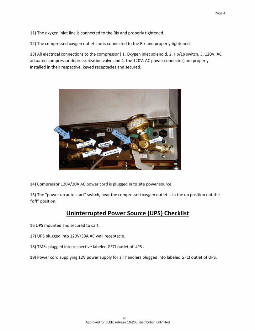
11) The oxygen inlet line is connected to the Rix and properly tightened.
12) The compressed oxygen outlet line is connected to the Rix and properly tightened.
13) All electrical connections to the compressor ( 1. Oxygen inlet solenoid, 2. Hp/Lp switch, 3. 120V. AC
actuated compressor depressurization valve and 4. the 120V. AC power connector) are properly
installed in their respective, keyed receptacles and secured.
14) Compressor 120V/20A AC power cord is plugged in to site power source.
15) The “power up auto start” switch, near the compressed oxygen outlet is in the up position not the
“off” position.
16 UPS mounted and secured to cart.
Uninterrupted Power Source (UPS) Checklist
17) UPS plugged into 120V/30A AC wall receptacle.
18) TMSs plugged into respective labeled GFCI outlet of UPS .
19) Power cord supplying 12V power supply for air handlers plugged into labeled GFCI outlet of UPS.
Page 4
20 Approved for public release 10-285; distribution unlimited

20) Oxygen Sample manifold mounted securely on cart with associated plumbing connected and secure.
Peripheral Checklist
21) Oxygen surge Cylinders on cart and secured by straps and ramp mechanism.
Page 5
21 Approved for public release 10-285; distribution unlimited
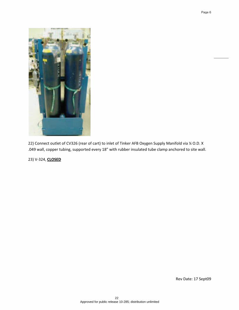
22) Connect outlet of CV326 (rear of cart) to inlet of Tinker AFB Oxygen Supply Manifold via ¼ O.D. X
.049 wall, copper tubing, supported every 18” with rubber insulated tube clamp anchored to site wall.
23) V-324,
CLOSED
Rev Date: 17 Sept09
Page 6
22 Approved for public release 10-285; distribution unlimited
6lpm Advanced Breadboard System Start-up
Oxygen Generator Start-up Checklist
! The following procedure should be used for start-up of the oxygen generators . This
procedure assumes that all items on the 6LPM Advanced Breadboard Pre-
Startup Checklist have been completed.
! The following procedure can be used if there is a power outage that lasts for more
than fifteen minutes (15 minutes is the amount of time that the Uninterrupted Power
Supply, (UPS) will power up the generators and air movers when the UPS batteries
are at full charge.
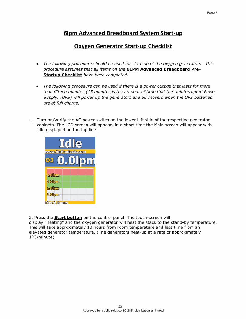
1. Turn on/Verify the AC power switch on the lower left side of the respective generator
cabinets. The LCD screen will appear. In a short time the Main screen will appear with
Idle displayed on the top line.
2. Press the Start button
display “Heating” and the oxygen generator will heat the stack to the stand-by temperature.
This will take approximately 10 hours from room temperature and less time from an
elevated generator temperature. (The generators heat-up at a rate of approximately
1°C/minute).
on the control panel. The touch-screen will
Page 7
23 Approved for public release 10-285; distribution unlimited
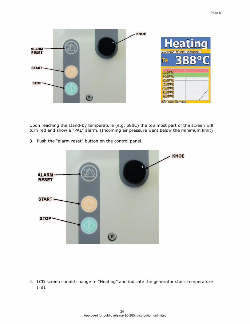
Upon reaching the stand-by temperature (e.g. 680C) the top most part of the screen will
turn red and show a “PAL” alarm. (Incoming air pressure went below the minimum limit)
3. Push the “alarm reset” button on the control panel.
4. LCD screen should change to “Heating” and indicate the generator stack temperature
(Ts).
Page 8
24 Approved for public release 10-285; distribution unlimited
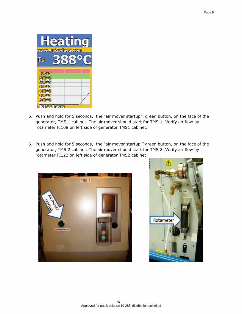
5. Push and hold for 5 seconds, the “air mover startup”, green button, on the face of the
generator, TMS 1 cabinet. The air mover should start for TMS 1. Verify air flow by
rotameter FI108 on left side of generator TMS1 cabinet.
6. Push and hold for 5 seconds, the “air mover startup,” green button, on the face of the
generator, TMS 2 cabinet. The air mover should start for TMS 2. Verify air flow by
rotameter FI122 on left side of generator TMS2 cabinet
Page 9
25 Approved for public release 10-285; distribution unlimited
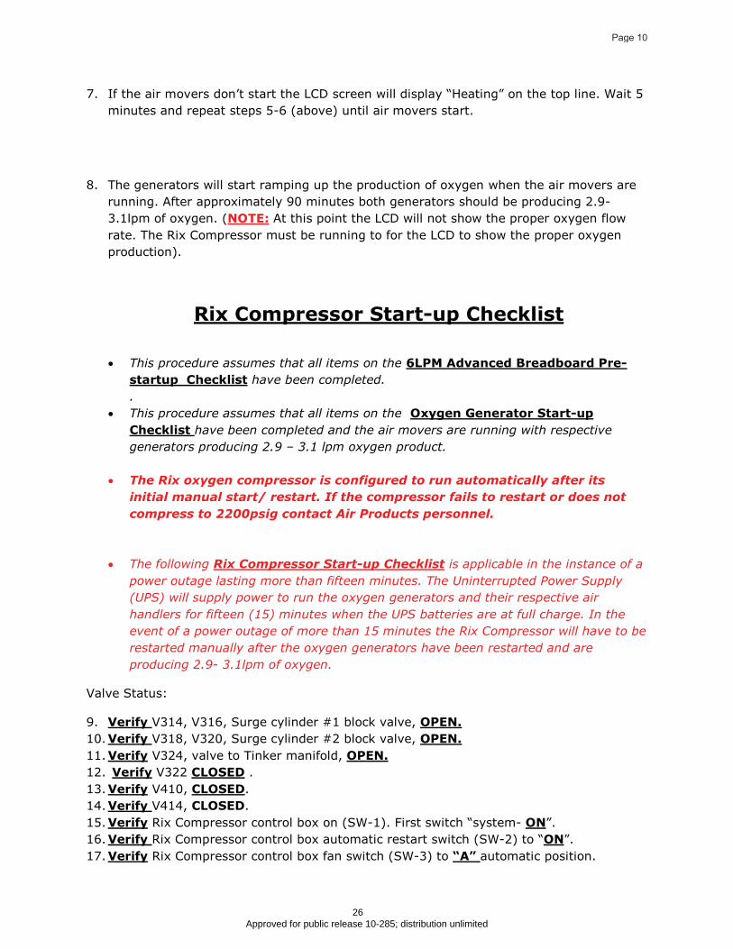
7. If the air movers don’t start the LCD screen will display “Heating” on the top line. Wait 5
minutes and repeat steps 5-6 (above) until air movers start.
8. The generators will start ramping up the production of oxygen when the air movers are
running. After approximately 90 minutes both generators should be producing 2.9-
3.1lpm of oxygen. (NOTE: At this point the LCD will not show the proper oxygen flow
rate. The Rix Compressor must be running to for the LCD to show the proper oxygen
production).
Rix Compressor Start-up Checklist
! This procedure assumes that all items on the 6LPM Advanced Breadboard Pre-
startup Checklist
.
have been completed.
! This procedure assumes that all items on the Oxygen Generator Start-up
Checklist have been completed and the air movers are running with respective
generators producing 2.9 – 3.1 lpm oxygen product.
! The Rix oxygen compressor is configured to run automatically after its
initial manual start/ restart. If the compressor fails to restart or does not
compress to 2200psig contact Air Products personnel.
! The following Rix Compressor Start-up Checklist
Valve Status:
is applicable in the instance of a
power outage lasting more than fifteen minutes. The Uninterrupted Power Supply
(UPS) will supply power to run the oxygen generators and their respective air
handlers for fifteen (15) minutes when the UPS batteries are at full charge. In the
event of a power outage of more than 15 minutes the Rix Compressor will have to be
restarted manually after the oxygen generators have been restarted and are
producing 2.9- 3.1lpm of oxygen.
9. Verify V314, V316, Surge cylinder #1 block valve,
10.
OPEN.
Verify V318, V320, Surge cylinder #2 block valve,
11.
OPEN.
Verify V324, valve to Tinker manifold,
12.
OPEN.
Verify V322 CLOSED
13.
.
Verify V410, CLOSED
14.
.
Verify
15.
V414, CLOSED.
Verify Rix Compressor control box on (SW-1). First switch “system- ON
16.
”.
Verify Rix Compressor control box automatic restart switch (SW-2) to “ON
17.
”.
Verify Rix Compressor control box fan switch (SW-3) to “A” automatic position.
Page 10
26 Approved for public release 10-285; distribution unlimited

.
18.Push and hold down Rix Compressor control box “start” button until compressor
runs continuously.
Rev Date: 10Sept09 1505
Page 11
27 Approved for public release 10-285; distribution unlimited

! This procedure assumes both oxygen generators are producing 2.9- 3.1 lpm per unit
Procedure for Sampling from the Oxygen Surge Cylinders
! The Rix compressor is operating and Surge Cylinders #1 and# 2 are pressurized above 1200psig
(read pressure on PI308).
1) Verify that surge cylinders #1 and #2 are pressurized above 1200 psig by ensuring
cylinder valves are OPEN, V314 OPEN, V318 OPEN
2) Verify that V322 is
, and checking pressure at PI308
CLOSED
3) Install oxygen sample cylinder (pipe plug end down, V418) into sample cylinder
rack until the pipe plug engages in the copper base stabilizer.
(inlet valve to sampling manifold)
4) Hand tighten the oxygen sample cylinder ring clamp to secure the sample cylinder.
5) Check pressure of PI411. (should be 0 psig)
6) SLOWLY OPEN
7) Remove ¼ “ Swagelok plug” from inlet of sample cylinder (V416).
V414 to depressurize the manifold (downstream of V410) to
reduce pressure in lines if it exists ( line pressure PI411).
8) Remove ¼ “ Swagelok cap” from outlet of sample line pigtail.
9) Connect outlet of sample line pigtail to inlet of (V416) of sample cylinder.
10) Status Check of oxygen sampling manifold valves -
CLOSED
11) PCV-402 backed out (turn counter-clockwise) allowing no flow of gas.
: V322, V410, V414,
12) Valve status check of 1 L. sample cylinder
CLOSED:
13)
V416, V418
SLOWLY OPEN
14) PI400 will read the surge cylinder pressure.
V322.
15) SLOWLY OPEN
410
15) Adjust PCV402 clockwise until PI404 reads 1200psi (oxygen is now filling sampling
manifold to V416).
PURGE SAMPLING MANIFOLD and Oxygen Sample Cylinder
16) CLOSE
17)
V322
SLOWLY OPEN
18)
V414 (vent lines until PI411 reads 100psig).
CLOSE
18) Repeat Step #12 –step #18 two more times
V414.
Page 12
28 Approved for public release 10-285; distribution unlimited

19) OPEN
20)
V322.
SLOWLY OPEN V416
21) Pressurize cylinder to 1200psig (PI411…will take 2-3 minutes)
(inlet to oxygen sample cylinder).
22) CLOSE
23)
V410.
SLOWLY OPEN V414 to vent/purge oxygen sample cylinder until PI411 reads
100psig, CLOSE
24)
V414
SLOWLY OPEN
25) Pressurize cylinder to 1200psig (PI411…will take 2-3 minutes)
V410
26) CLOSE
27)
V410.
SLOWLY OPEN V414 to vent/purge oxygen sample cylinder until PI411 reads
100psig, CLOSE
28) REPEAT Steps #24 -#27 (to purge sample cylinder of residual air).
V414
OXYGEN SAMPLE CAPTURE
29) SLOWLY OPEN
30) Pressurize cylinder to 1200psig (PI411…will take 2-3 minutes)
V410
31) CLOSE
32)
V416
CLOSE
33)
V410.
CLOSE
34)
V322
SLOWLY OPEN
35) When PI411 is “0 psig”
V414 to depressurize manifold lines.
CLOSE
36) Unmake ¼ “ Swagelok” fitting at inlet of V416.
V414
37) Plug V416 inlet with ¼” Swagelok plug.
38) Loosen the oxygen sample cylinder ring clamp .
39) Lift and remove the oxygen sample cylinder from it’s support.
40) Replace ¼” Swagelok cap
41) Package sample cylinder per instructions for shipping.
on oxygen sample outlet pigtail.
42) SLOWLY OPEN
43)
V414.
SLOWLY OPEN
44) Turn PCV402 counter clock until no regulator outlet pressure is on PI404.
V410.
45) CLOSE
V410, V414
Rev Date: 17Sept09
Page 13
29 Approved for public release 10-285; distribution unlimited
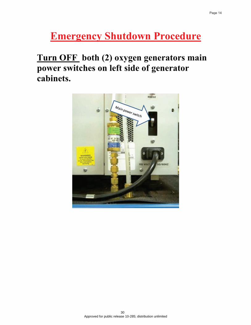
Emergency Shutdown Procedure
Turn OFF both (2) oxygen generators main
power switches on left side of generator
cabinets.
Page 14
30 Approved for public release 10-285; distribution unlimited

Turn the Rix Compressor System Switch to
the OFF Position
CLOSE the Cylinders Shutoff Valve
Page 15
31 Approved for public release 10-285; distribution unlimited

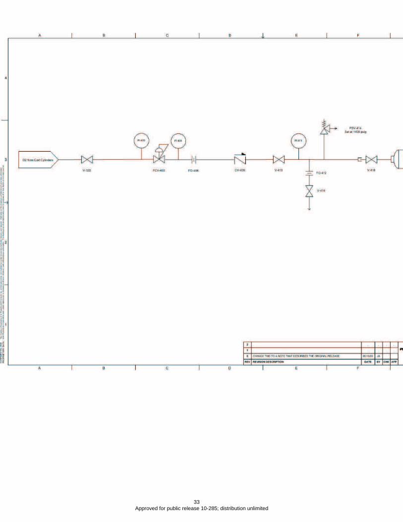
Page 16
32 Approved for public release 10-285; distribution unlimited
Page 17
33 Approved for public release 10-285; distribution unlimited
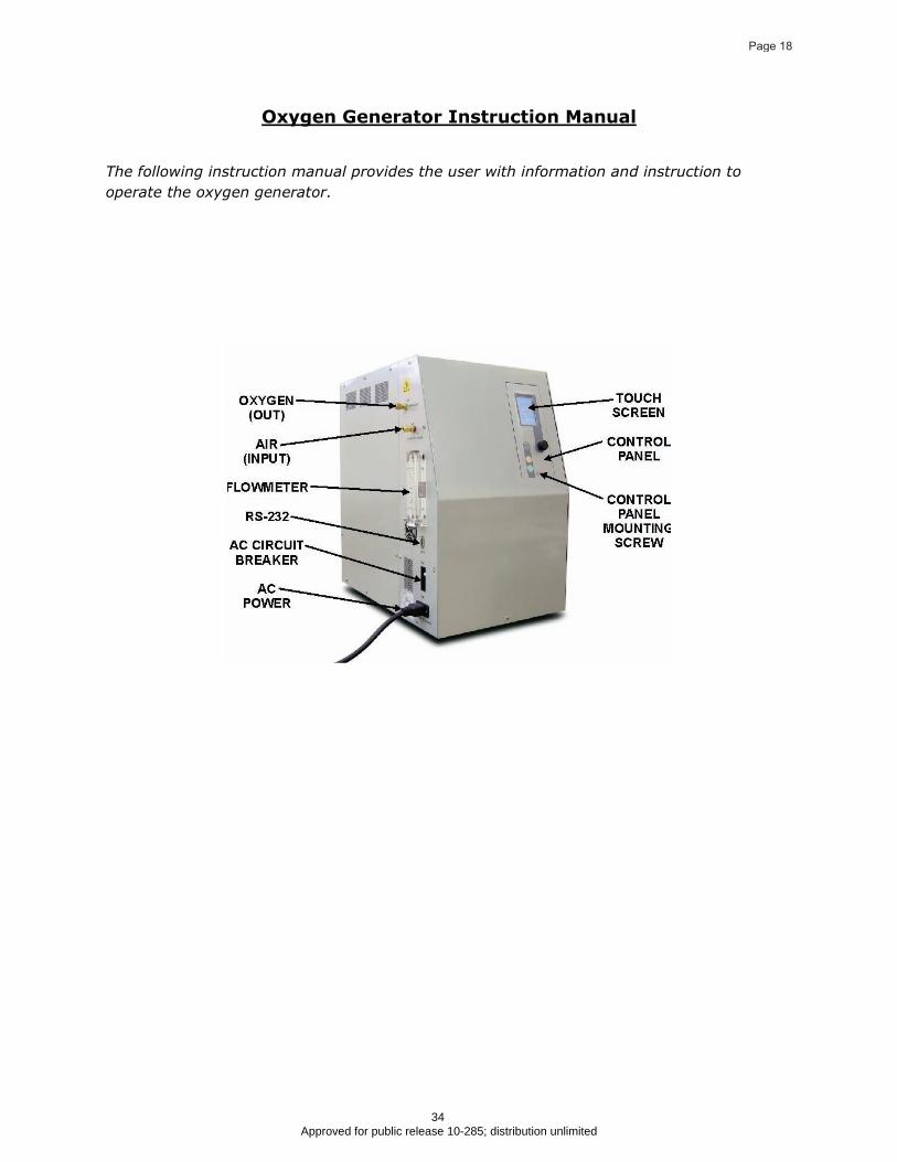
Oxygen Generator Instruction Manual
The following instruction manual provides the user with information and instruction to
operate the oxygen generator.
Page 18
34 Approved for public release 10-285; distribution unlimited
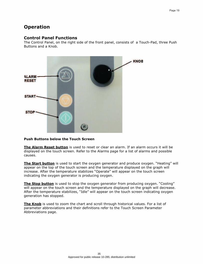
Operation
Control Panel FunctionsThe Control Panel, on the right side of the front panel, consists of a Touch-Pad, three Push
Buttons and a Knob.
Push Buttons below the Touch Screen
The Alarm Reset button is used to reset or clear an alarm. If an alarm occurs it will be
displayed on the touch screen. Refer to the Alarms page for a list of alarms and possible
causes.
The Start button is used to start the oxygen generator and produce oxygen. “Heating” will
appear on the top of the touch screen and the temperature displayed on the graph will
increase. After the temperature stabilizes “Operate” will appear on the touch screen
indicating the oxygen generator is producing oxygen.
The Stop button
After the temperature stabilizes, “Idle” will appear on the touch screen indicating oxygen
generation has stopped.
is used to stop the oxygen generator from producing oxygen. “Cooling”
will appear on the touch screen and the temperature displayed on the graph will decrease.
The Knob is used to zoom the chart and scroll through historical values. For a list of
parameter abbreviations and their definitions refer to the Touch Screen Parameter
Abbreviations page.
Page 19
35 Approved for public release 10-285; distribution unlimited
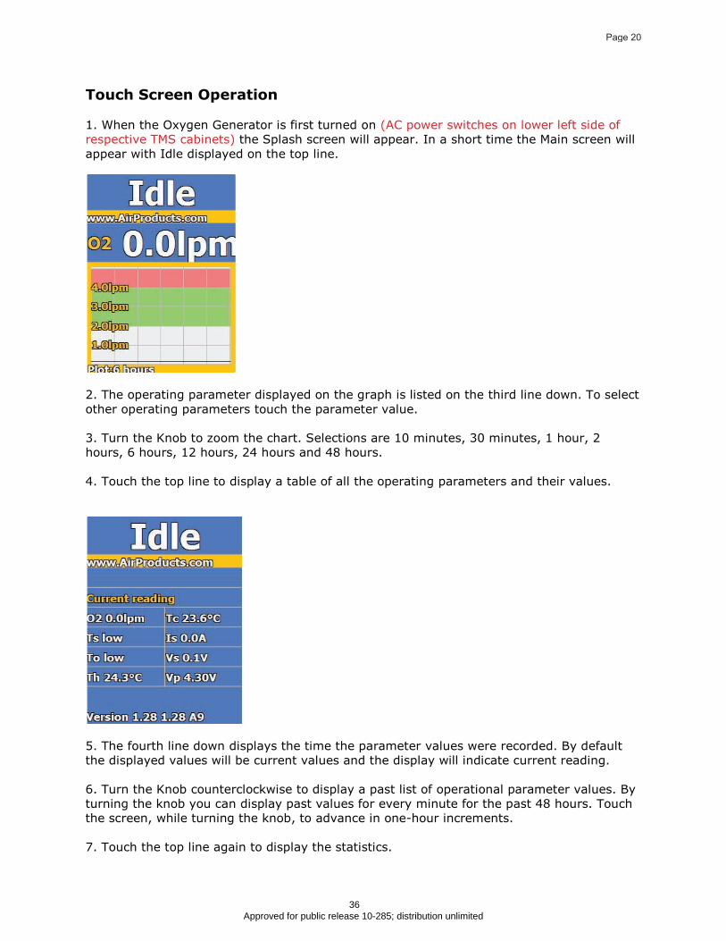
Touch Screen Operation
1. When the Oxygen Generator is first turned on (AC power switches on lower left side of
respective TMS cabinets) the Splash screen will appear. In a short time the Main screen will
appear with Idle displayed on the top line.
2. The operating parameter displayed on the graph is listed on the third line down. To select
other operating parameters touch the parameter value.
3. Turn the Knob to zoom the chart. Selections are 10 minutes, 30 minutes, 1 hour, 2
hours, 6 hours, 12 hours, 24 hours and 48 hours.
4. Touch the top line to display a table of all the operating parameters and their values.
5. The fourth line down displays the time the parameter values were recorded. By default
the displayed values will be current values and the display will indicate current reading.
6. Turn the Knob counterclockwise to display a past list of operational parameter values. By
turning the knob you can display past values for every minute for the past 48 hours. Touch
the screen, while turning the knob, to advance in one-hour increments.
7. Touch the top line again to display the statistics.
Page 20
36 Approved for public release 10-285; distribution unlimited

8. Touch the top line again to return to the Main screen.
Oxygen Generation
Start Oxygen Generation
1.Turn the oxygen generator on. The Main screen will appear.
2. Press the Start button on the control panel. The touch-screen will display Heating and the
oxygen generator will heat the stack to the operating temperature. This will take
approximately 6 hours.
3. The operating parameter displayed on the graph is listed on the third line down. To select
other operating parameters touch the parameter value.
4. Turn the knob to zoom the chart. Selections are 10 minutes, 30 minutes, 1 hour, 2 hours,
6 hours, 12 hours, 24 hours and 48 hours.
5. As the generator is heating touch Heating to display a list of operating parameters and
their values.
Page 21
37 Approved for public release 10-285; distribution unlimited
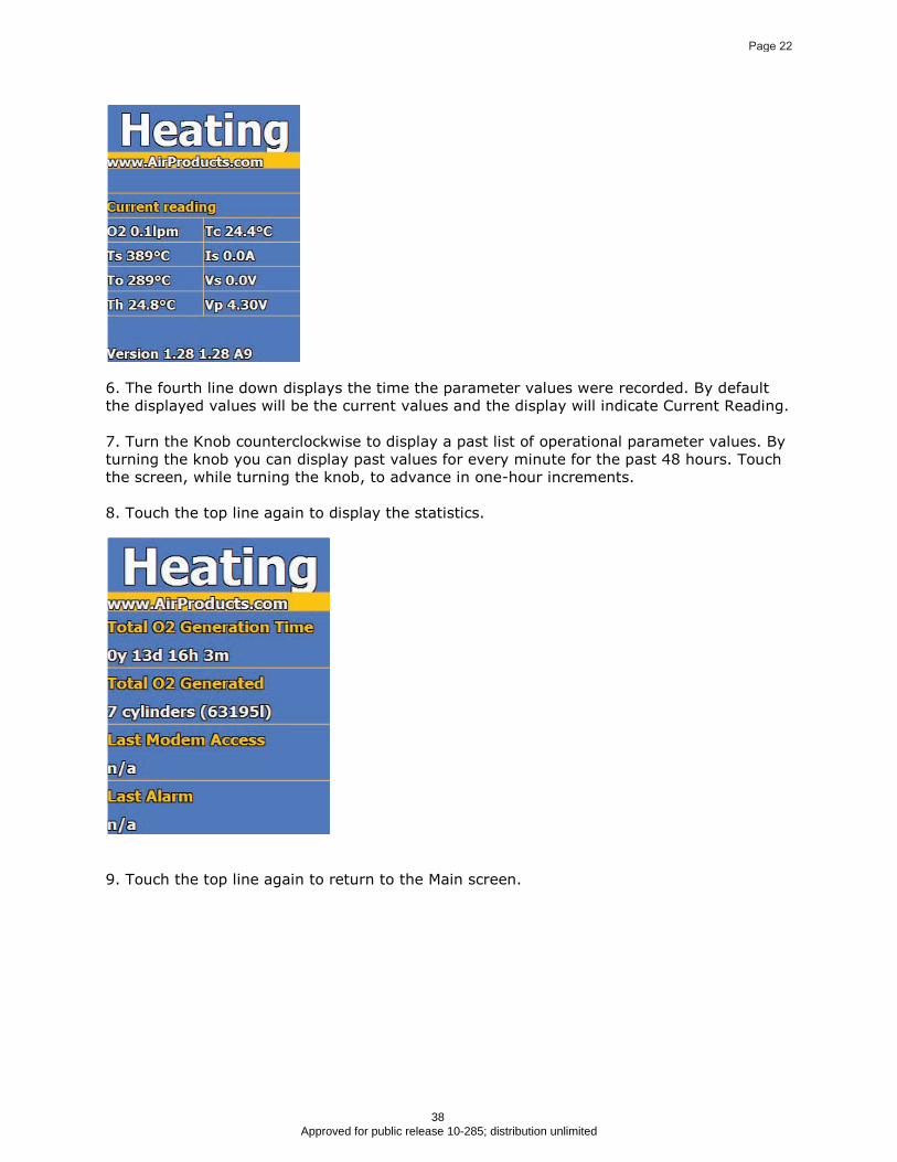
6. The fourth line down displays the time the parameter values were recorded. By default
the displayed values will be the current values and the display will indicate Current Reading.
7. Turn the Knob counterclockwise to display a past list of operational parameter values. By
turning the knob you can display past values for every minute for the past 48 hours. Touch
the screen, while turning the knob, to advance in one-hour increments.
8. Touch the top line again to display the statistics.
9. Touch the top line again to return to the Main screen.
Page 22
38 Approved for public release 10-285; distribution unlimited

Oxygen Generation
1. After reaching the operating temperature Operate will appear on the top of the screen
and the generator will start producing oxygen.
2. As the generator is producing oxygen touch Operate to display a list of operating
parameters and their values.
3. The fourth line down displays the time the parameter values were recorded. By default
the displayed values will be the current values and the display will indicate Current Reading.
4. Turn the Knob counterclockwise to display a past list of operational parameter values. By
turning the knob you can display past values for every minute for the past 48 hours. Touch
the screen, while turning the knob, to advance in one-hour increments.
5. Touch the top line again to display the statistics.
Page 23
39 Approved for public release 10-285; distribution unlimited
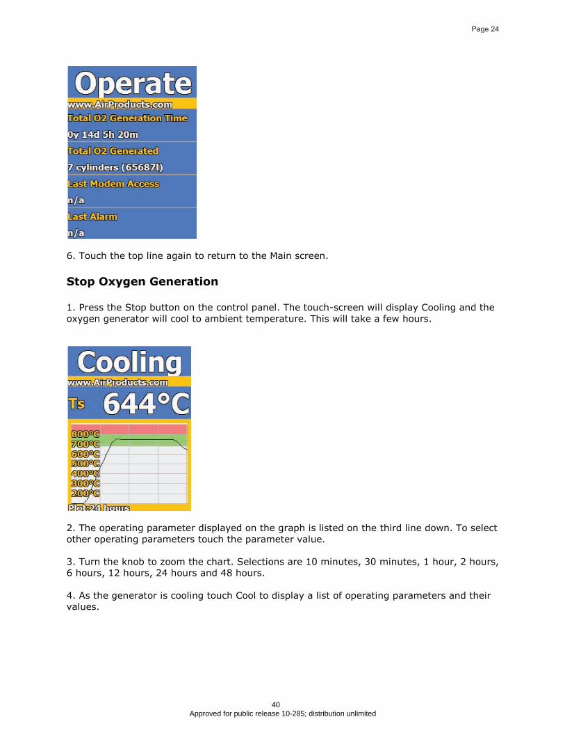
6. Touch the top line again to return to the Main screen.
Stop Oxygen Generation
1. Press the Stop button on the control panel. The touch-screen will display Cooling and the
oxygen generator will cool to ambient temperature. This will take a few hours.
2. The operating parameter displayed on the graph is listed on the third line down. To select
other operating parameters touch the parameter value.
3. Turn the knob to zoom the chart. Selections are 10 minutes, 30 minutes, 1 hour, 2 hours,
6 hours, 12 hours, 24 hours and 48 hours.
4. As the generator is cooling touch Cool to display a list of operating parameters and their
values.
Page 24
40 Approved for public release 10-285; distribution unlimited

5. The fourth line down displays the time the parameter values were recorded. By default
the displayed values will be the current values and the display will indicate Current Reading.
6. Turn the Knob counterclockwise to display a past list of operational parameter values. By
turning the knob you can display past values for every minute for the past 48 hours. Touch
the screen, while turning the knob, to advance in one-hour increments.
7. Touch the top line again to display the statistics.
8. Touch the top line again to return to the Main screen.
Page 25
41 Approved for public release 10-285; distribution unlimited
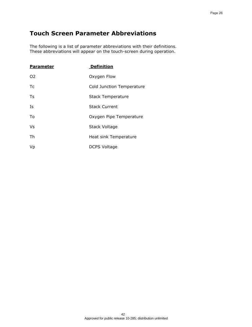
Touch Screen Parameter Abbreviations
The following is a list of parameter abbreviations with their definitions.
These abbreviations will appear on the touch-screen during operation.
Parameter Definition
O2 Oxygen Flow
Tc Cold Junction Temperature
Ts Stack Temperature
Is Stack Current
To Oxygen Pipe Temperature
Vs Stack Voltage
Th Heat sink Temperature
Vp DCPS Voltage
Page 26
42 Approved for public release 10-285; distribution unlimited

Alarms
The following alarms will be displayed on the touch screen if they
occur. Press Alarm Reset, on the front panel, to clear the alarm.
TAH Stack temperature went above the maximum limit.
OCA Stack current went above the maximum limit.
PAL Incoming air pressure went below the minimum limit
FAL Outgoing oxygen flow went below the minimum limit. Normal status
for FAL light depends on the operating mode of the oxygen delivery
system. The FAL (Flow Alarm Low) will not be illuminated when the
compressor is operating and delivering oxygen to the user. The
generators will indicate a FAL however when the compressor is shut
down. During normal operation the FAL light indicates that the oxygen
being continuously produced by the generators is being bled off
through the relief valves inside the generator cabinets. The relief
valves are located upstream of the oxygen flow meter and therefore
the flow meter correctly registers the lack of oxygen flow to the
compressor. When the compressor restarts, the relief valves close and
the flow of oxygen through the flow meter is reestablished
RAMP Stack temperature ramp rate went above the maximum limit.
SHORT Stack voltage dropped below minimum while stack current was above
threshold.
SNK Heat sink temperature rose above maximum limit.
THRM Stack or oxygen pipe thermocouples may be shorted or disconnected.
CURR Stack current went above the maximum limit.
VROR Reference voltage went out of range.
VPOR Power supply voltage went out of range.
V24OR V+24V power went out of range.
V5OR V+5V power went out of range.
COR AC line measurement circuit went out of range.
ACFLT The AC line voltage went below the minimum limit.
OK No alarms indicated.
Page 27
43 Approved for public release 10-285; distribution unlimited
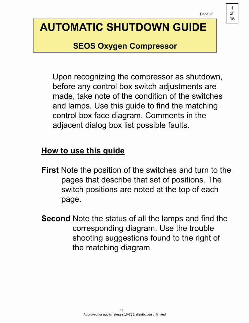
AUTOMATIC SHUTDOWN GUIDE
SEOS Oxygen Compressor
Upon recognizing the compressor as shutdown,
before any control box switch adjustments are
made, take note of the condition of the switches
and lamps. Use this guide to find the matching
control box face diagram. Comments in the
adjacent dialog box list possible faults.
How to use this guide
First Note the position of the switches and turn to the
pages that describe that set of positions. The
switch positions are noted at the top of each
page.
Second Note the status of all the lamps and find the
corresponding diagram. Use the trouble
shooting suggestions found to the right of
the matching diagram
1
of
15Page 28
44 Approved for public release 10-285; distribution unlimited
L1 L2
L3
L4
L6L5
SW1
SYS
SW2
ARS
SW3
FAN
SW4
COMP
L1 L2
L3
L4
L7L6L5
SW1
SYS
SW2
ARS
SW3
FAN
SW4
COMP
L1 L2
L3
L4
L7L6L5
SW1
SYS
SW2
ARS
SW3
FAN
SW4
COMP
L1 L2
L3
L4
L7L6L5
SW1
SYS
SW2
ARS
SW3
FAN
SW4
COMP
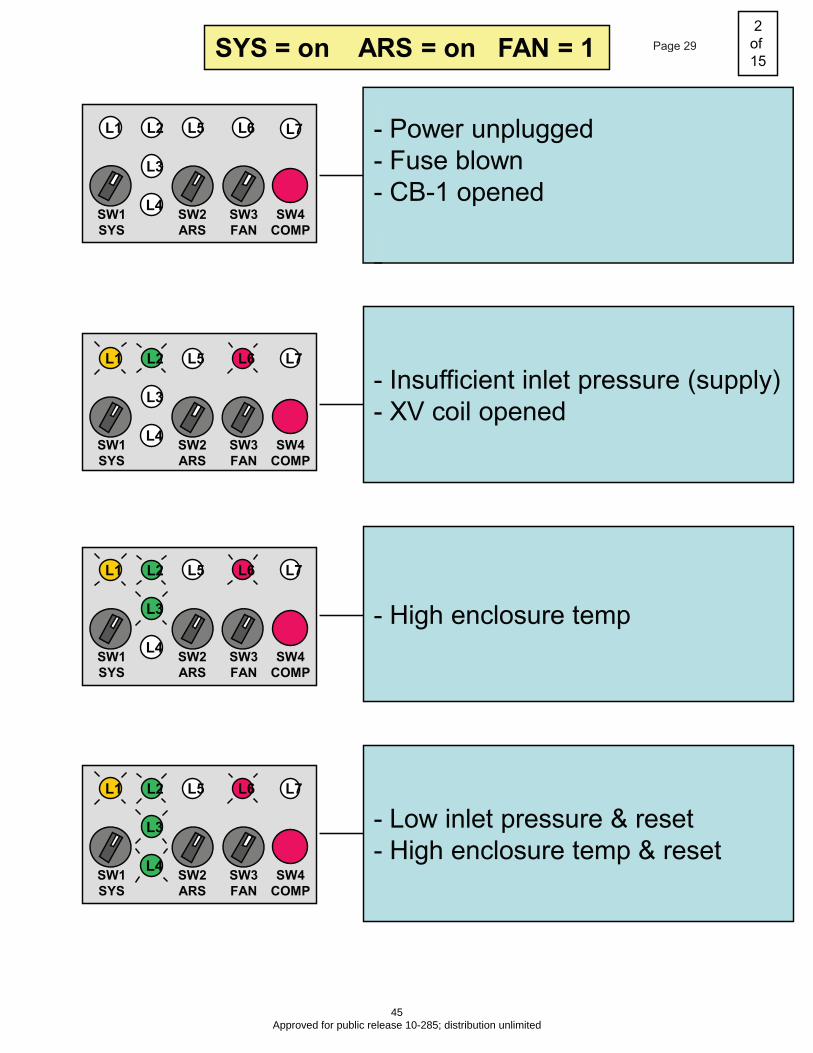
- Power unplugged
- Fuse blown
- CB-1 opened
- Insufficient inlet pressure (supply)
- XV coil opened
- High enclosure temp
- Low inlet pressure & reset
- High enclosure temp & reset
SYS = on ARS = on FAN = 1
L7
2
of
15Page 29
45 Approved for public release 10-285; distribution unlimited

L1 L2
L3
L4
L6L5
SW1
SYS
SW2
ARS
SW3
FAN
SW4
COMP
L1 L2
L3
L4
L7L6L5
SW1
SYS
SW2
ARS
SW3
FAN
SW4
COMP
- Shutdown on high disch. press.
SYS = on ARS = on FAN = 1
L7
(Compressor audibly not running)
- CB-2 opened
- Rix motor contactor coil open
- Relay R1 coil open
- Rix motor thermal OL open
3
of
15Page 30
46 Approved for public release 10-285; distribution unlimited

L1 L2
L3
L4
L7L6L5
SW1
SYS
SW2
ARS
SW3
FAN
SW4
COMP
L1 L2
L3
L4
L7L6L5
SW1
SYS
SW2
ARS
SW3
FAN
SW4
COMP
L1 L2
L3
L4
L7L6L5
SW1
SYS
SW2
ARS
SW3
FAN
SW4
COMP
L1 L2
L3
L4
L7L6L5
SW1
SYS
SW2
ARS
SW3
FAN
SW4
COMP
SYS = on ARS = on FAN = 0
- Power unplugged
- Fuse blown
- CB-1 opened
- Insufficient inlet pressure (supply)
- XV coil opened
- High enclosure temp
- Low inlet pressure & reset
- High enclosure temp & reset
4
of
15Page 31
47 Approved for public release 10-285; distribution unlimited

(Compressor audibly not running)
- CB-2 opened
- Relay R1 coil open
- Rix motor contactor coil open
L1 L2
L3
L4
L7L6L5
SW1
SYS
SW2
ARS
SW3
FAN
SW4
COMP
L1 L2
L3
L4
L7L6L5
SW1
SYS
SW2
ARS
SW3
FAN
SW4
COMP
L1 L2
L3
L4
L7L6L5
SW1
SYS
SW2
ARS
SW3
FAN
SW4
COMP
SYS = on ARS = on FAN = 0
(Compressor audibly not running)
- Rix motor thermal OL open
- Shutdown on high disch. press.
5
of
15Page 32
48 Approved for public release 10-285; distribution unlimited
L1 L2
L3
L4
L7L6L5
SW1
SYS
SW2
ARS
SW3
FAN
SW4
COMP
L1 L2
L3
L4
L7L6L5
SW1
SYS
SW2
ARS
SW3
FAN
SW4
COMP
L1 L2
L3
L4
L7L6L5
SW1
SYS
SW2
ARS
SW3
FAN
SW4
COMP
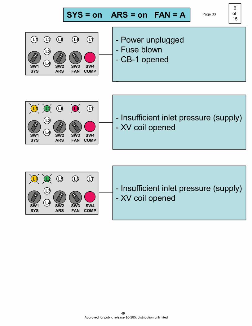
SYS = on ARS = on FAN = A
- Power unplugged
- Fuse blown
- CB-1 opened
- Insufficient inlet pressure (supply)
- XV coil opened
- Insufficient inlet pressure (supply)
- XV coil opened
6
of
15Page 33
49 Approved for public release 10-285; distribution unlimited

L1 L2
L3
L4
L7L6L5
SW1
SYS
SW2
ARS
SW3
FAN
SW4
COMP
L1 L2
L3
L4
L7L6L5
SW1
SYS
SW2
ARS
SW3
FAN
SW4
COMP
L1 L2
L3
L4
L7L6L5
SW1
SYS
SW2
ARS
SW3
FAN
SW4
COMP
L1 L2
L3
L4
L7L6L5
SW1
SYS
SW2
ARS
SW3
FAN
SW4
COMP
L1 L2
L3
L4
L7L6L5
SW1
SYS
SW2
ARS
SW3
FAN
SW4
COMP
SYS = on ARS = on FAN = A
- High enclosure temp
- Shutdown on high disch. press.
(Compressor audibly not running)
- CB-2 opened
- Relay R1 coil open
- Rix motor contactor coil open
- Rix motor thermal OL open
- High enclosure temp
- Shutdown on high disch. press.
7
of
15Page 34
50 Approved for public release 10-285; distribution unlimited
L1 L2
L3
L4
L7L6L5
SW1
SYS
SW2
ARS
SW3
FAN
SW4
COMP
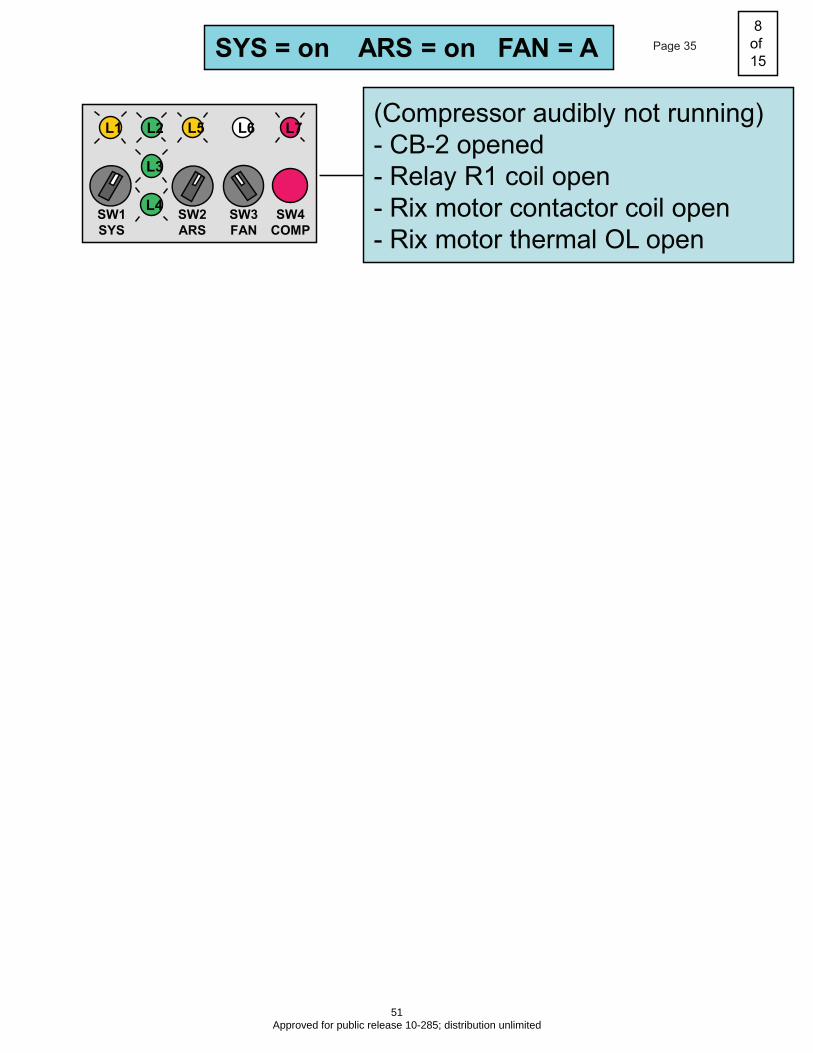
SYS = on ARS = on FAN = A
(Compressor audibly not running)
- CB-2 opened
- Relay R1 coil open
- Rix motor contactor coil open
- Rix motor thermal OL open
8
of
15Page 35
51 Approved for public release 10-285; distribution unlimited
L1 L2
L3
L4
L7L6L5
SW1
SYS
SW2
ARS
SW3
FAN
SW4
COMP
L1 L2
L3
L4
L7L6L5
SW1
SYS
SW2
ARS
SW3
FAN
SW4
COMP
L1 L2
L3
L4
L7L6L5
SW1
SYS
SW2
ARS
SW3
FAN
SW4
COMP
L1 L2
L3
L4
L7L6L5
SW1
SYS
SW2
ARS
SW3
FAN
SW4
COMP
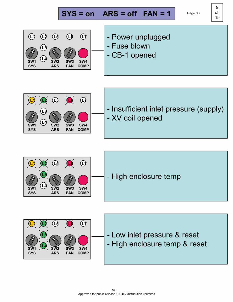
SYS = on ARS = off FAN = 1
- Power unplugged
- Fuse blown
- CB-1 opened
- Insufficient inlet pressure (supply)
- XV coil opened
- High enclosure temp
- Low inlet pressure & reset
- High enclosure temp & reset
9
of
15Page 36
52 Approved for public release 10-285; distribution unlimited
L1 L2
L3
L4
L7L6L5
SW1
SYS
SW2
ARS
SW3
FAN
SW4
COMP
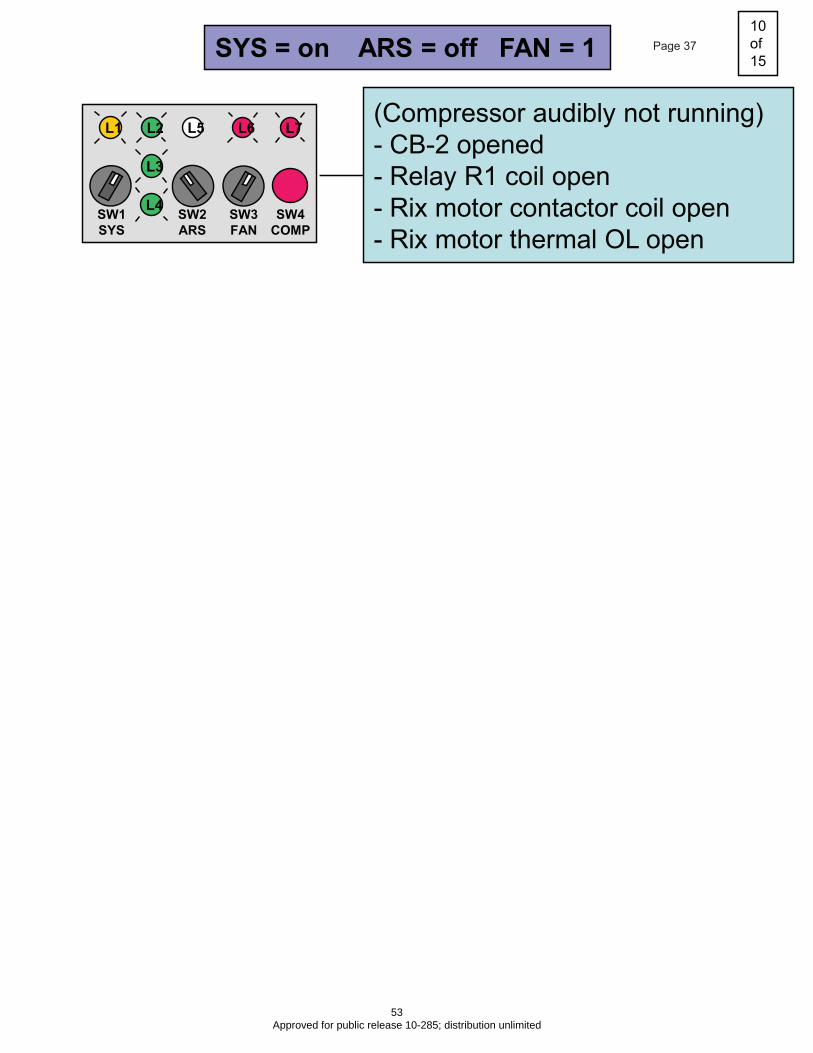
SYS = on ARS = off FAN = 1
(Compressor audibly not running)
- CB-2 opened
- Relay R1 coil open
- Rix motor contactor coil open
- Rix motor thermal OL open
10
of
15Page 37
53 Approved for public release 10-285; distribution unlimited

L1 L2
L3
L4
L7L6L5
SW1
SYS
SW2
ARS
SW3
FAN
SW4
COMP
L1 L2
L3
L4
L7L6L5
SW1
SYS
SW2
ARS
SW3
FAN
SW4
COMP
L1 L2
L3
L4
L7L6L5
SW1
SYS
SW2
ARS
SW3
FAN
SW4
COMP
L1 L2
L3
L4
L7L6L5
SW1
SYS
SW2
ARS
SW3
FAN
SW4
COMP
SYS = on ARS = off FAN = 0
- Power unplugged
- Fuse blown
- CB-1 opened
- Insufficient inlet pressure (supply)
- XV coil opened
- High enclosure temp
- Low inlet pressure & reset
- High enclosure temp & reset
- Shutdown on high disch. press.
- Relay R1 coil open
- Rix motor contactor coil open
11
of
15Page 38
54 Approved for public release 10-285; distribution unlimited
L1 L2
L3
L4
L7L6L5
SW1
SYS
SW2
ARS
SW3
FAN
SW4
COMP
L1 L2
L3
L4
L7L6L5
SW1
SYS
SW2
ARS
SW3
FAN
SW4
COMP
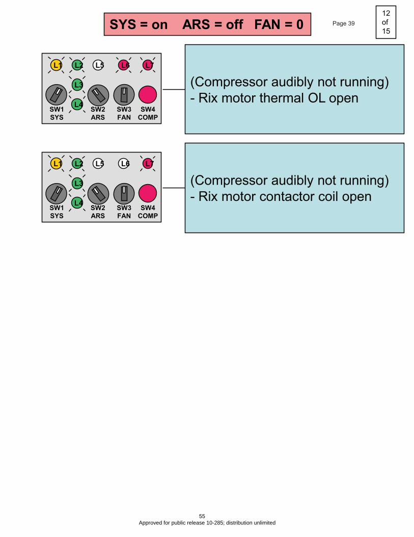
SYS = on ARS = off FAN = 0
(Compressor audibly not running)
- Rix motor contactor coil open
(Compressor audibly not running)
- Rix motor thermal OL open
12
of
15Page 39
55 Approved for public release 10-285; distribution unlimited
L1 L2
L3
L4
L7L6L5
SW1
SYS
SW2
ARS
SW3
FAN
SW4
COMP
L1 L2
L3
L4
L7L6L5
SW1
SYS
SW2
ARS
SW3
FAN
SW4
COMP
L1 L2
L3
L4
L7L6L5
SW1
SYS
SW2
ARS
SW3
FAN
SW4
COMP
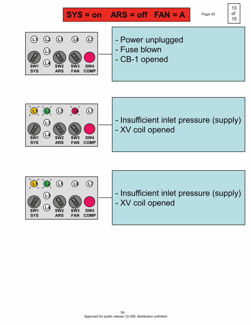
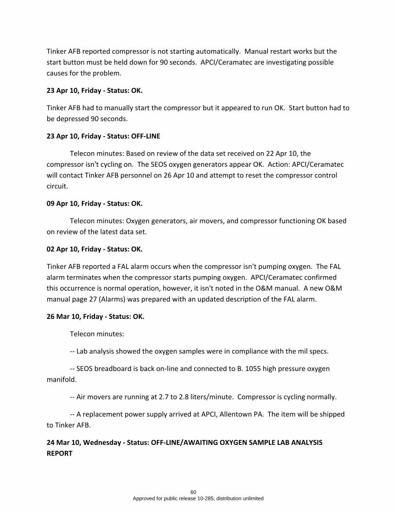
SYS = on ARS = off FAN = A
- Power unplugged
- Fuse blown
- CB-1 opened
- Insufficient inlet pressure (supply)
- XV coil opened
- Insufficient inlet pressure (supply)
- XV coil opened
13
of
15Page 40
56 Approved for public release 10-285; distribution unlimited

L1 L2
L3
L4
L7L6L5
SW1
SYS
SW2
ARS
SW3
FAN
SW4
COMP
L1 L2
L3
L4
L7L6L5
SW1
SYS
SW2
ARS
SW3
FAN
SW4
COMP
L1 L2
L3
L4
L7L6L5
SW1
SYS
SW2
ARS
SW3
FAN
SW4
COMP
L1 L2
L3
L4
L7L6L5
SW1
SYS
SW2
ARS
SW3
FAN
SW4
COMP
L1 L2
L3
L4
L7L6L5
SW1
SYS
SW2
ARS
SW3
FAN
SW4
COMP
SYS = on ARS = off FAN = A
- High enclosure temp
- High enclosure temp
- Low inlet pressure & reset
- High enclosure temp & reset
- Shutdown on high disch. press.
- Relay R1 coil open
- Low inlet pressure & reset
- High enclosure temp & reset
- Shutdown on high disch. press.
- Relay R1 coil open
(Compressor audibly not running)
- Rix motor thermal OL open
- Rix motor contactor coil open
14
of
15Page 41
57 Approved for public release 10-285; distribution unlimited

APPENDIX C – Narrative Logbook
58 Approved for public release 10-285; distribution unlimited

EARLY FIELD ASSESSMENT OF SOLID ELECTROLYTE OXYGEN SEPARATOR
AT OC‐ALC, TINKER AFB OK
NARRATIVE LOGBOOK
Next Oxygen Sample Due: 18 Jun 10
11 Jun 10, Friday ‐ Status: ON‐LINE BUT SUPPLING OXYGEN AT REDUCED CAPACITY
Telecon minutes: Oxygen generator #1 (left side) air mover is not working. APCI will ship a new air mover to Tinker. Tinker plans to install the air mover. Oxygen generator #2 is supplying oxygen at 2.4 LPM. Compressor is OK. Compressor auto‐start function appears OK. APCI maintenance trip to Tinker is currently pre‐planned for sometime during the month of July, pending contract modification to extend the SEOS Tinker effort to Nov 10 and personnel availability.
04 Jun 10, Friday ‐ Status: ON‐LINE BUT SUPPLYING OXYGEN AT REDUCED CAPACITY
Telecon minutes: Tinker reported construction in the area may be causing power outages. Presently, Oxygen Generator #1 is off‐line. Its air mover will not start. Oxygen Generator #2 is working but at a slightly reduced capacity (2.5 LPM). Tinker plans to troubleshoot Generator #1. Compressor is ok. Supply cylinder pressure appears adequate. A pressure of 1800 psig was noted on 04 Jun 10. Tinker plans to take an oxygen sample next week.
02 Jun 10, Wednesday ‐ Status: OFF‐LINE.
Tinker AFB reported the shop lost power over the weekend. The breadboard was restarted and is in the heating cycle. Sometime today the DC ramp will be started.
07 May 10, Friday ‐ Status: OFF‐LINE.
Telecon minutes: Tinker AFB reported the facility had a prolonged power outage. The SEOS breadboard shutdown for an estimated three hours. Stack temperature dropped to an estimated 517°C. The device was restarted and is currently in the heat‐up phase. Full startup should occur today. Also, the compressor auto start function will be checked.
29 Apr 10, Thursday ‐ Status: OK.
59 Approved for public release 10-285; distribution unlimited
Tinker AFB reported compressor is not starting automatically. Manual restart works but the start button must be held down for 90 seconds. APCI/Ceramatec are investigating possible causes for the problem.
23 Apr 10, Friday ‐ Status: OK.
Tinker AFB had to manually start the compressor but it appeared to run OK. Start button had to be depressed 90 seconds.
23 Apr 10, Friday ‐ Status: OFF‐LINE
Telecon minutes: Based on review of the data set received on 22 Apr 10, the compressor isn't cycling on. The SEOS oxygen generators appear OK. Action: APCI/Ceramatec will contact Tinker AFB personnel on 26 Apr 10 and attempt to reset the compressor control circuit.
09 Apr 10, Friday ‐ Status: OK.
Telecon minutes: Oxygen generators, air movers, and compressor functioning OK based on review of the latest data set.
02 Apr 10, Friday ‐ Status: OK.
Tinker AFB reported a FAL alarm occurs when the compressor isn't pumping oxygen. The FAL alarm terminates when the compressor starts pumping oxygen. APCI/Ceramatec confirmed this occurrence is normal operation, however, it isn't noted in the O&M manual. A new O&M manual page 27 (Alarms) was prepared with an updated description of the FAL alarm.
26 Mar 10, Friday ‐ Status: OK.
Telecon minutes:
‐‐ Lab analysis showed the oxygen samples were in compliance with the mil specs.
‐‐ SEOS breadboard is back on‐line and connected to B. 1055 high pressure oxygen manifold.
‐‐ Air movers are running at 2.7 to 2.8 liters/minute. Compressor is cycling normally.
‐‐ A replacement power supply arrived at APCI, Allentown PA. The item will be shipped to Tinker AFB.
24 Mar 10, Wednesday ‐ Status: OFF‐LINE/AWAITING OXYGEN SAMPLE LAB ANALYSIS REPORT
60 Approved for public release 10-285; distribution unlimited

Tinker AFB reported the shop experienced a long term power outage over the weekend. Tinker AFB restarted the breadboard. Oxygen samples were taken and sent to the lab for analysis. If the samples show the oxygen still in compliance with the mil specs, the breadboard will go back on‐line.
08 Mar 10, Monday ‐ Status: OFF‐LINE/AWAITING OXYGEN SAMPLE LAB ANALYSIS REPORT
Tinker AFB replaced the right side air mover and powered‐up the breadboard. Voltage at the right side air mover power supply was measured at 13.9 Volts. Oxygen samples will be collected. Breadboard will go back on‐line after the oxygen samples show compliance with the mil specs.
05 Mar 10, Friday ‐ Status: OFF‐LINE/AWAITING OXYGEN SAMPLE LAB ANALYSIS REPORT
Telecon minutes:
‐‐ Tinker AFB reported left side oxygen generator OK, right side air mover shutdown, and compressor OK. Oxygen samples were collected and sent to the lab. Results should be available next week.
‐‐ Way forward: Tinker AFB will attempt to replace the right side air mover. A spare air mover is on‐site at Tinker AFB. Tinker AFB will check the voltage supplied to the right side air mover. If needed, APCI and Ceramatec plan to support Tinker AFB in these actions via telephonic communication.
02 Mar 10, Tuesday ‐ Status: OFF‐LINE ‐ Tinker AFB reported the breadboard malfunctioned on 22 Feb 10.
19 Feb 10, Friday ‐ Status: OFF‐LINE/AWAITING OXYGEN SAMPLE LAB ANALYSIS REPORT ‐ APCI completed breadboard preventative maintenance and repair at Tinker AFB (17‐19 Feb 10). The breadboard is operating normally. Air mover #1 was replaced. Air mover #2 was rebuilt. Power supply for air mover #2 was replaced and rewired. The oxygen generators and SEOS electrochemical stacks are functioning normally. The compressor wiring and timers were modified. The compressor modifications enable the compressor to restart after extended low pressure or zero pressure conditions. A small leak was detected in the compressor outlet piping but it should have negligible impact on breadboard operations. The compressor high pressure setting remains at 2100 psig and the low pressure setting was reset to 1700 psig. An oxygen sample must be taken to show continued compliance with the military specifications.
22 Jan 10, Friday ‐ Status: OFF‐LINE ‐ APCI breadboard maintenance trip to Tinker AFB planned for
28 and 29 Jan 10. APCI plans to send two people.
61 Approved for public release 10-285; distribution unlimited

13 Jan 10, Wednesday ‐ Status: OFF‐LINE ‐ Tinker AFB reported the oxygen generator air movers are
experiencing electrical problems. The air movers supply ambient air to the SEOS electrochemical stacks. Tinker AFB isolated the SEOS breadboard and reconnected their oxygen supply manifold to the vendor oxygen bottles. The oxygen generator and compressor electrical problems will be resolved during the upcoming APCI maintenance trip. The trip is tentatively planned for the week of 25 Jan 10. Most likely APCI will need facility access for 2 days. Confirmation of the exact trip dates will be provided shortly.
12 Jan 10, Tuesday ‐ Status: OFF‐LINE
Telecon minutes:
‐‐ Tinker AFB reported Oxygen Generator #1 is showing an alarm mode and Oxygen Generator #2 is not running. The electrochemical stack temperatures on both units are near the normal operational temperature; hence, APCI will assist Tinker AFB personnel in attempting to restart the generators.
‐‐ Tinker AFB reported the compressor is running OK but disconnecting and reconnecting the compressor electrical connector may be causing excessive wear at the connector pins. The group noted compressor vibration might be causing the current issues. APCI will suggest an approach to mitigate compressor vibration.
‐‐ 18 Dec 09 Action Item (Status: OPEN): Date for the APCI maintenance trip to Tinker AFB is TBD pending review of personnel availability.
23 Dec 09, Wednesday ‐ Status: OK ‐ Tinker AFB reported laboratory test reports for SEOS oxygen (samples N6350 and N6352) show compliance with the appropriate military standards.
18 Dec 09, Friday ‐ Status: OK
Telecon minutes:
‐‐ On 17 Dec 09 Tinker AFB noted the compressor was down but after reconnecting the compressor control box the problem resolved.
‐‐ Action Item: APCI will determine if the planned February preventative maintenance trip can be scheduled earlier. Trip would be used to resolve the compressor intermittent electrical problem and conduct general preventative maintenance.
15 Dec 09, Tuesday ‐ Status: OK ‐ Compressor is working.
14 Dec 09, Monday ‐ Status: OFF‐LINE ‐ Compressor is down. New control box should be installed
today.
08 Dec 09, Tuesday ‐ Status: OK ‐ APCI shipped new compressor control box to Tinker AFB.
62 Approved for public release 10-285; distribution unlimited

07 Dec 09, Monday ‐ Status: OFF‐LINE ‐ Tinker AFB reported compressor is down. Disconnecting
and reconnecting compressor control box resolved the problem.
04 Dec 09, Friday ‐ Status: OK
Telecon minutes:
‐‐ Tinker AFB reported when the compressor shutdown on 01 Dec 09 the troubleshooting guide was of limited value in helping to define the problem. Intermittent connections at the power cable connector most likely made troubleshooting more difficult. APCI suggested using duct tape on the power connector to help secure it.
‐‐ Tinker AFB will retain the current oxygen manifold valves which have integral check valves. The check valves prevent SEOS from filling the manifold bottles. Presently, Tinker AFB believes the two SEOS breadboard oxygen bottles will meet their needs.
‐‐ Tinker AFB will return the APCI tool kit. Also, Tinker AFB will ship the breadboard packaging foam to APCI.
02 Dec 09, Wednesday‐ Status: OK ‐ Power cable from control box to compressor found loose. Cable
retightened.
01 Dec 09, Tuesday ‐ Status: OFF‐LINE ‐ Oxygen generators OK. Compressor shut down.
20 Nov 09, Friday ‐ Status: OK ‐ SEOS breadboard installed and operating properly at OC‐ALC, Tinker AFB OK. Several facility personnel trained on start‐up, operation, shutdown, oxygen sampling, and data logging. Tinker AFB laboratory confirmed SEOS oxygen complies with mil spec for aviator's breathing oxygen. Next oxygen sampling required in 45 days (04 Jan 10). First aircraft oxygen bottle filled with SEOS oxygen. User questionnaire and performance metrics are under development.
63 Approved for public release 10-285; distribution unlimited
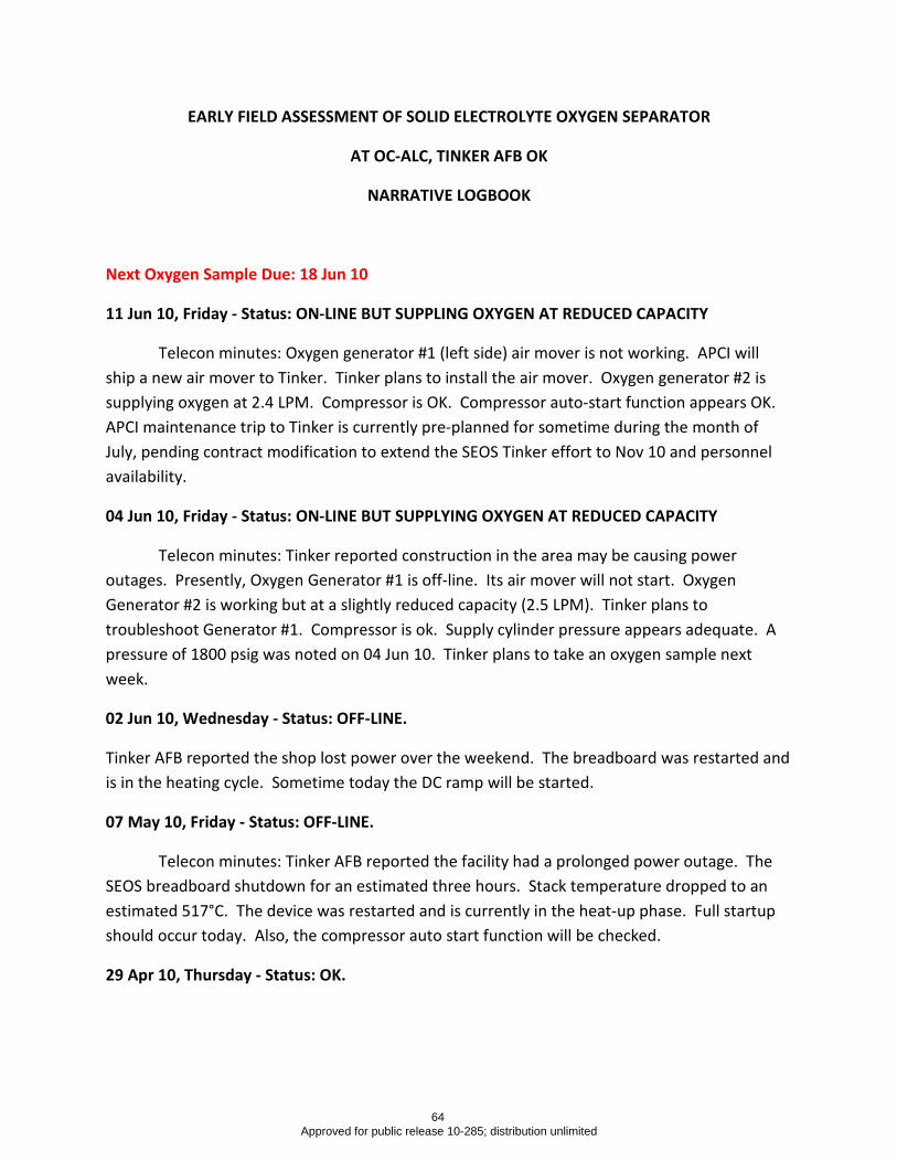
EARLY FIELD ASSESSMENT OF SOLID ELECTROLYTE OXYGEN SEPARATOR
AT OC-ALC, TINKER AFB OK
NARRATIVE LOGBOOK
Next Oxygen Sample Due: 18 Jun 10
11 Jun 10, Friday - Status: ON-LINE BUT SUPPLING OXYGEN AT REDUCED CAPACITY
Telecon minutes: Oxygen generator #1 (left side) air mover is not working. APCI will ship a new air mover to Tinker. Tinker plans to install the air mover. Oxygen generator #2 is supplying oxygen at 2.4 LPM. Compressor is OK. Compressor auto-start function appears OK. APCI maintenance trip to Tinker is currently pre-planned for sometime during the month of July, pending contract modification to extend the SEOS Tinker effort to Nov 10 and personnel availability.
04 Jun 10, Friday - Status: ON-LINE BUT SUPPLYING OXYGEN AT REDUCED CAPACITY
Telecon minutes: Tinker reported construction in the area may be causing power outages. Presently, Oxygen Generator #1 is off-line. Its air mover will not start. Oxygen Generator #2 is working but at a slightly reduced capacity (2.5 LPM). Tinker plans to troubleshoot Generator #1. Compressor is ok. Supply cylinder pressure appears adequate. A pressure of 1800 psig was noted on 04 Jun 10. Tinker plans to take an oxygen sample next week.
02 Jun 10, Wednesday - Status: OFF-LINE.
Tinker AFB reported the shop lost power over the weekend. The breadboard was restarted and is in the heating cycle. Sometime today the DC ramp will be started.
07 May 10, Friday - Status: OFF-LINE.
Telecon minutes: Tinker AFB reported the facility had a prolonged power outage. The SEOS breadboard shutdown for an estimated three hours. Stack temperature dropped to an estimated 517°C. The device was restarted and is currently in the heat-up phase. Full startup should occur today. Also, the compressor auto start function will be checked.
29 Apr 10, Thursday - Status: OK.
64 Approved for public release 10-285; distribution unlimited

Tinker AFB reported compressor is not starting automatically. Manual restart works but the start button must be held down for 90 seconds. APCI/Ceramatec are investigating possible causes for the problem.
23 Apr 10, Friday - Status: OK.
Tinker AFB had to manually start the compressor but it appeared to run OK. Start button had to be depressed 90 seconds.
23 Apr 10, Friday - Status: OFF-LINE
Telecon minutes: Based on review of the data set received on 22 Apr 10, the compressor isn't cycling on. The SEOS oxygen generators appear OK. Action: APCI/Ceramatec will contact Tinker AFB personnel on 26 Apr 10 and attempt to reset the compressor control circuit.
09 Apr 10, Friday - Status: OK.
Telecon minutes: Oxygen generators, air movers, and compressor functioning OK based on review of the latest data set.
02 Apr 10, Friday - Status: OK.
Tinker AFB reported a FAL alarm occurs when the compressor isn't pumping oxygen. The FAL alarm terminates when the compressor starts pumping oxygen. APCI/Ceramatec confirmed this occurrence is normal operation, however, it isn't noted in the O&M manual. A new O&M manual page 27 (Alarms) was prepared with an updated description of the FAL alarm.
26 Mar 10, Friday - Status: OK.
Telecon minutes:
-- Lab analysis showed the oxygen samples were in compliance with the mil specs.
-- SEOS breadboard is back on-line and connected to B. 1055 high pressure oxygen manifold.
-- Air movers are running at 2.7 to 2.8 liters/minute. Compressor is cycling normally.
-- A replacement power supply arrived at APCI, Allentown PA. The item will be shipped to Tinker AFB.
24 Mar 10, Wednesday - Status: OFF-LINE/AWAITING OXYGEN SAMPLE LAB ANALYSIS REPORT
65 Approved for public release 10-285; distribution unlimited
Tinker AFB reported the shop experienced a long term power outage over the weekend. Tinker AFB restarted the breadboard. Oxygen samples were taken and sent to the lab for analysis. If the samples show the oxygen still in compliance with the mil specs, the breadboard will go back on-line.
08 Mar 10, Monday - Status: OFF-LINE/AWAITING OXYGEN SAMPLE LAB ANALYSIS REPORT
Tinker AFB replaced the right side air mover and powered-up the breadboard. Voltage at the right side air mover power supply was measured at 13.9 Volts. Oxygen samples will be collected. Breadboard will go back on-line after the oxygen samples show compliance with the mil specs.
05 Mar 10, Friday - Status: OFF-LINE/AWAITING OXYGEN SAMPLE LAB ANALYSIS REPORT
Telecon minutes:
-- Tinker AFB reported left side oxygen generator OK, right side air mover shutdown, and compressor OK. Oxygen samples were collected and sent to the lab. Results should be available next week.
-- Way forward: Tinker AFB will attempt to replace the right side air mover. A spare air mover is on-site at Tinker AFB. Tinker AFB will check the voltage supplied to the right side air mover. If needed, APCI and Ceramatec plan to support Tinker AFB in these actions via telephonic communication.
02 Mar 10, Tuesday - Status: OFF-LINE - Tinker AFB reported the breadboard malfunctioned on 22 Feb 10.
19 Feb 10, Friday - Status: OFF-LINE/AWAITING OXYGEN SAMPLE LAB ANALYSIS REPORT - APCI completed breadboard preventative maintenance and repair at Tinker AFB (17-19 Feb 10). The breadboard is operating normally. Air mover #1 was replaced. Air mover #2 was rebuilt. Power supply for air mover #2 was replaced and rewired. The oxygen generators and SEOS electrochemical stacks are functioning normally. The compressor wiring and timers were modified. The compressor modifications enable the compressor to restart after extended low pressure or zero pressure conditions. A small leak was detected in the compressor outlet piping but it should have negligible impact on breadboard operations. The compressor high pressure setting remains at 2100 psig and the low pressure setting was reset to 1700 psig. An oxygen sample must be taken to show continued compliance with the military specifications.
22 Jan 10, Friday - Status: OFF-LINE - APCI breadboard maintenance trip to Tinker AFB planned for
28 and 29 Jan 10. APCI plans to send two people.
66 Approved for public release 10-285; distribution unlimited
13 Jan 10, Wednesday - Status: OFF-LINE - Tinker AFB reported the oxygen generator air movers are experiencing electrical problems. The air movers supply ambient air to the SEOS electrochemical stacks. Tinker AFB isolated the SEOS breadboard and reconnected their oxygen supply manifold to the vendor oxygen bottles. The oxygen generator and compressor electrical problems will be resolved during the upcoming APCI maintenance trip. The trip is tentatively planned for the week of 25 Jan 10. Most likely APCI will need facility access for 2 days. Confirmation of the exact trip dates will be provided shortly.
12 Jan 10, Tuesday - Status: OFF-LINE
Telecon minutes:
-- Tinker AFB reported Oxygen Generator #1 is showing an alarm mode and Oxygen Generator #2 is not running. The electrochemical stack temperatures on both units are near the normal operational temperature; hence, APCI will assist Tinker AFB personnel in attempting to restart the generators.
-- Tinker AFB reported the compressor is running OK but disconnecting and reconnecting the compressor electrical connector may be causing excessive wear at the connector pins. The group noted compressor vibration might be causing the current issues. APCI will suggest an approach to mitigate compressor vibration.
-- 18 Dec 09 Action Item (Status: OPEN): Date for the APCI maintenance trip to Tinker AFB is TBD pending review of personnel availability.
23 Dec 09, Wednesday - Status: OK - Tinker AFB reported laboratory test reports for SEOS oxygen
(samples N6350 and N6352) show compliance with the appropriate military standards.
18 Dec 09, Friday - Status: OK
Telecon minutes:
-- On 17 Dec 09 Tinker AFB noted the compressor was down but after reconnecting the compressor control box the problem resolved.
-- Action Item: APCI will determine if the planned February preventative maintenance trip can be scheduled earlier. Trip would be used to resolve the compressor intermittent electrical problem and conduct general preventative maintenance.
15 Dec 09, Tuesday - Status: OK - Compressor is working.
14 Dec 09, Monday - Status: OFF-LINE - Compressor is down. New control box should be installed
today.
08 Dec 09, Tuesday - Status: OK - APCI shipped new compressor control box to Tinker AFB.
67 Approved for public release 10-285; distribution unlimited
07 Dec 09, Monday - Status: OFF-LINE - Tinker AFB reported compressor is down. Disconnecting
and reconnecting compressor control box resolved the problem.
04 Dec 09, Friday - Status: OK
Telecon minutes:
-- Tinker AFB reported when the compressor shutdown on 01 Dec 09 the troubleshooting guide was of limited value in helping to define the problem. Intermittent connections at the power cable connector most likely made troubleshooting more difficult. APCI suggested using duct tape on the power connector to help secure it.
-- Tinker AFB will retain the current oxygen manifold valves which have integral check valves. The check valves prevent SEOS from filling the manifold bottles. Presently, Tinker AFB believes the two SEOS breadboard oxygen bottles will meet their needs.
-- Tinker AFB will return the APCI tool kit. Also, Tinker AFB will ship the breadboard packaging foam to APCI.
02 Dec 09, Wednesday- Status: OK - Power cable from control box to compressor found loose. Cable
retightened.
01 Dec 09, Tuesday - Status: OFF-LINE - Oxygen generators OK. Compressor shut down.
20 Nov 09, Friday - Status: OK - SEOS breadboard installed and operating properly at Building 1055,
OC-ALC, Tinker AFB OK. Several facility personnel trained on start-up, operation, shutdown, oxygen sampling, and data logging. Tinker AFB laboratory confirmed SEOS oxygen complies with mil spec for aviator's breathing oxygen. Next oxygen sampling required in 45 days (04 Jan 10). First aircraft oxygen bottle filled with SEOS oxygen. User questionnaire and performance metrics are under development.
68 Approved for public release 10-285; distribution unlimited

APPENDIX D – Laboratory Oxygen Analysis Reports
69 Approved for public release 10-285; distribution unlimited
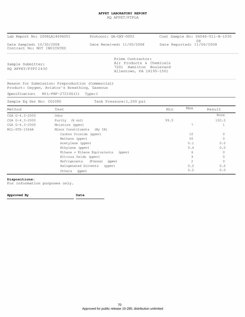
07 Dec 09, Monday ‐ Status: OFF‐LINE ‐ Tinker AFB reported compressor is down. Disconnecting
essor con lem. and reconnecting compr trol box resolved the prob
04 Dec 09, Friday ‐ Status: OK
Telecon minutes:
‐‐ Tinker AFB reported when the compre troubleshooting guide was of limited value in helping to define the problem. Intermittent connections at the power cable
ore difficult. APCI suggested using duct tape on the
ssor shutdown on 01 Dec 09 the
connector most likely made troubleshooting mpower connector to help secure it.
‐‐ Tinker AFB will retain the current oxygen manifold alves which have integral check v lves. esently, Tinker AFB elieves th two
SEOS breadboa ygen bottles will meet their needs.
v aeThe check valves prevent SEOS from filling the manifold bottles. Pr b
rd ox
‐‐ Tinker the APCI tool kit. Also, Tinker AFB will ship th ad ard packaging to APCI.
AFB will return e bre bofoam
02 Dec 09, Wed ower cable from control box to compressor found se. Cable
retightened.
nesday‐ Status: OK ‐ P loo
01 Dec 09, Tues erators OK. Compressor shut down day ‐ Status: OFF‐LINE ‐ Oxygen gen .
20 Nov 09, Frid rd installed and operating properly at Building 1055,
OC‐ALC, Tinker AF veral acility personnel trained on s rt‐up, operation, shutdow xygen pling, and data logging. Tinker AFB laboratory confirmed SEOS oxygen complies with mil spec for
. Next oxygen sampling required in 45 days (04 Jan 10). First aircraft oxygen bottle filled with SEOS oxygen. User questionnaire and performance metrics are under development.
ay ‐ Status: OK ‐ SEOS readbob a
B OK. Se f ta n, osamaviator's breathing oxygen
Lab Report No: 2008LA14694001 Protocol: GA-OXY-0003 Cust Sample No: 06046-011-B-1030
08
Date Sampled: 10/30/2008 Date Received: 11/05/2008 Date Reported: 11/06/2008
Contract No: NOT INDICATED
Sample Submitter:
HQ AFPET/PTPT 2430
Prime Contractor:
Air Products & Chemicals
7201 Hamilton Boulevard
Allentown, PA 18195-1501
Reason for Submission: Preproduction (Commercial)
Product: Oxygen, Aviator's Breathing, Gaseous
Specification: MIL-PRF-27210G(1) Type:I
Sample Eq Ser No: CG1080 Tank Pressure:1,200 psi
Method Test Min Max Result
CGA G-4.3-2000 Odor None
CGA G-4.3-2000 Purity (% vol) 99.5 100.0
CGA G-4.3-2000 Moisture (ppmv) 7 1
MIL-STD-1564A Minor Constituents (By IR) Carbon Dioxide (ppmv) 10 0
Methane (ppmv) 50 0
Acetylene (ppmv) 0.1 0.0
Ethylene (ppmv) 0.4 0.0
Ethane + Ethane Equivalents (ppmv) 6 0
Nitrous Oxide (ppmv) 4 0
Refrigerants (Freons) (ppmv) 2 0
Halogenated Solvents (ppmv) 0.2 0.0
Others (ppmv) 0.2 0.0
Dispositions:
For information purposes only.
Approved By Date
AFPET LABORATORY REPORT
HQ AFPET/PTPLA
70 Approved for public release 10-285; distribution unlimited
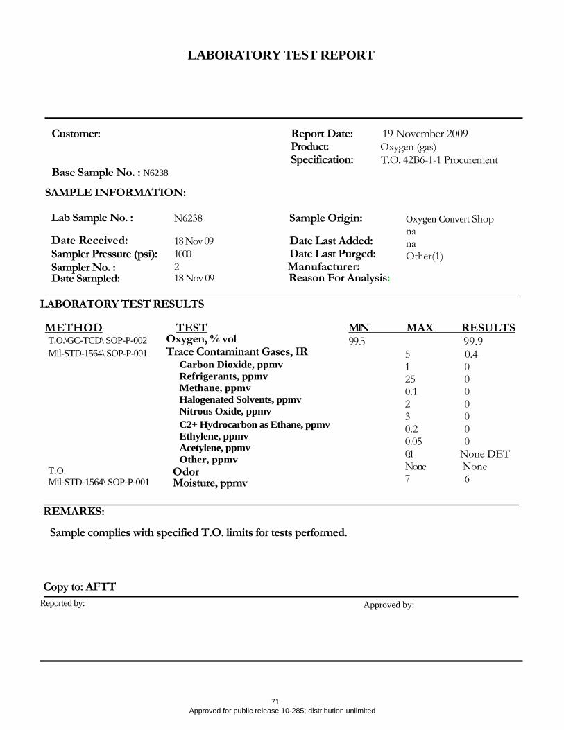
Lab Sample No. :
Date Received: Sampler Pressure (psi): Sampler No. : Date Sampled:
N6238 Sample Origin:
18 Nov 09 Date Last Added: 1000 Date Last Purged: 2 Manufacturer: 18 Nov 09 Reason For Analysis:
METHOD T.O.\GC-TCD\ SOP-P-002 Mil-STD-1564\ SOP-P-001
T.O. Mil-STD-1564\ SOP-P-001
TEST Oxygen, % vol Trace Contaminant Gases, IR
Carbon Dioxide, ppmv Refrigerants, ppmv Methane, ppmv Halogenated Solvents, ppmv Nitrous Oxide, ppmv C2+ Hydrocarbon as Ethane, ppmv Ethylene, ppmv Acetylene, ppmv Other, ppmv
Odor Moisture, ppmv
Reported by: Approved by:
REMARKS:
Sample complies with specified T.O. limits for tests performed.
Copy to: AFTT
MIN MAX RESULTS99.5 99.9
5 0.4 1 0 25 0 0.1 0 2 0 3 0 0.2 0 0.05 0 0.1 None DET None None 7 6
LABORATORY TEST RESULTS
Oxygen Convert Shop na na Other(1)
Customer: Report Date: 19 November 2009 Product: Oxygen (gas) Specification: T.O. 42B6-1-1 Procurement
Base Sample No. : N6238
SAMPLE INFORMATION:
LABORATORY TEST REPORT
71 Approved for public release 10-285; distribution unlimited

Customer: Report Date: 23 December 2009 Product: Liquid Oxygen Specification: T.O. 42B6-1-1 Procurement
Base Sample No. : N6352
SAMPLE INFORMATION:
Lab Sample No. : N6352 Date Received: 22 Dec 09 Sampler Pressure (psi): Sampler No. : Date Sampled:
B 22 Dec 09
Sample Origin:Date Last Added: Date Last Purged: Manufacturer: Reason For Analysis:
N/A other
LABORATORY TEST RESULTS TEST
Oxygen, % vol Trace Contaminant Gases, IR
Carbon Dioxide, ppmv Refrigerants, ppmv Methane, ppmv Halogenated Solvents, ppmv Nitrous Oxide, ppmv C2+ Hydrocarbon as Ethane, ppmv Ethylene, ppmv Acetylene, ppmv Other, ppmv
T.O. Odor Mil-STD-1564\ SOP-P-001 Moisture, ppmv
METHOD -T.O.\GC-TCD\ SOP-P-002
Mil-STD-1564\ SOP-P-001
1 25 0.1 2 3 0.2 0.05 0.1 None 7
0.2 0 00 00 00
None DET None 5
MIN MAX RESULTS 99.5 99.9
REMARKS:
Sample complies with specified T.O. limits for tests performed.
Copy to: AFTT Reported by: Approved by:
LABORATORY TEST REPORT
72 Approved for public release 10-285; distribution unlimited
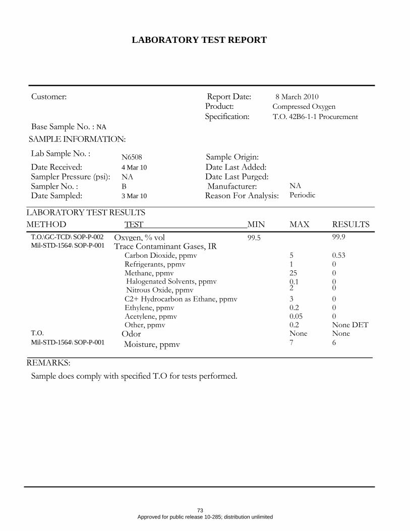
REMARKS: Sample does comply with specified T.O for tests performed.
Lab Sample No. : N6508 Sample Origin:
Date Received: 4 Mar 10 Date Last Added: Sampler Pressure (psi): NA Date Last Purged: Sampler No. : B Manufacturer: NA Date Sampled: 3 Mar 10 Reason For Analysis: Periodic
LABORATORY TEST RESULTS METHOD TEST MIN MAX RESULTS
T.O.\GC-TCD\ SOP-P-002 Oxygen, % vol 99.5 99.9Mil-STD-1564\ SOP-P-001 Trace Contaminant Gases, IR
Carbon Dioxide, ppmv 5 0.53 Refrigerants, ppmv 1 0 Methane, ppmv 25 0 Halogenated Solvents, ppmv,
Nitrous Oxide, ppmv 0.1 2
0 0
C2+ Hydrocarbon as Ethane, ppmv 3 0 Ethylene, ppmv 0.2 0 Acetylene, ppmv 0.05 0 Other, ppmv 0.2 None DET
T.O. Odor None None Mil-STD-1564\ SOP-P-001 Moisture, ppmv 7 6
Customer: Report Date: 8 March 2010 Product: Compressed Oxygen Specification: T.O. 42B6-1-1 Procurement
Base Sample No. : NA
SAMPLE INFORMATION:
LABORATORY TEST REPORT
73 Approved for public release 10-285; distribution unlimited
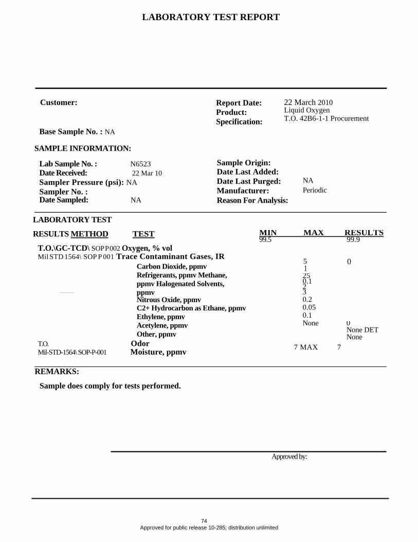
Customer: Report Date:
Product: Specification:
22 March 2010 Liquid Oxygen T.O. 42B6-1-1 Procurement
Base Sample No. : NA
SAMPLE INFORMATION:
Lab Sample No. : N6523 Date Received: 22 Mar 10 Sampler Pressure (psi): NA Sampler No. : Date Sampled: NA
Sample Origin:Date Last Added: Date Last Purged: Manufacturer: Reason For Analysis:
NA Periodic
LABORATORY TEST
RESULTS METHOD TEST
T.O.\GC-TCD\ SOP-P-002 Oxygen, % vol Mil-STD-1564\ SOP-P-001 Trace Contaminant Gases, IR 5 0
1 25 0.1 2 3 0.2 0.05 0.1 None
7 MAX 7
0None DET None
MIN MAX RESULTS99.5 99.9
Carbon Dioxide, ppmv Refrigerants, ppmv Methane, ppmv Halogenated Solvents, ppmv Nitrous Oxide, ppmv C2+ Hydrocarbon as Ethane, ppmv Ethylene, ppmv Acetylene, ppmv Other, ppmv
T.O. Odor Mil-STD-1564\ SOP-P-001 Moisture, ppmv
LABORATORY TEST REPORT
REMARKS:
Sample does comply for tests performed.
Approved by:
74 Approved for public release 10-285; distribution unlimited
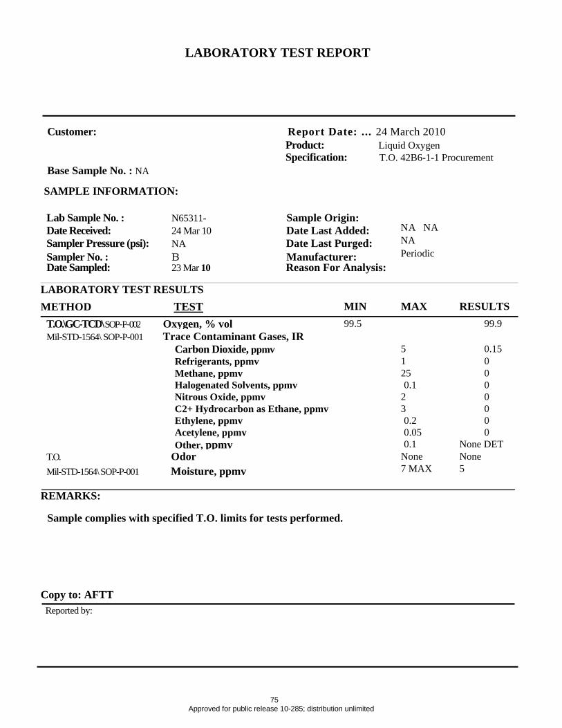
LABORATORY TEST REPORT
Customer: Report Date: ... 24 March 2010 Product: Liquid Oxygen Specification: T.O. 42B6-1-1 Procurement
Base Sample No. : NA
SAMPLE INFORMATION:
Lab Sample No. : N65311- Sample Origin: Date Received: 24 Mar 10 Date Last Added: Sampler Pressure (psi): NA Date Last Purged: Sampler No. : B Manufacturer: Date Sampled: 23 Mar 10 Reason For Analysis:
NA NA NA Periodic
LABORATORY TEST RESULTS METHOD TEST MIN MAX RESULTS
T.O.\GC-TCD\ SOP-P-002 Oxygen, % vol 99.5 99.9 Mil-STD-1564\ SOP-P-001 Trace Contaminant Gases, IR
Carbon Dioxide, ppmv 5 0.151 0Refrigerants, ppmv25 0Methane, ppmv
Halogenated Solvents, ppmv 0.1 0Nitrous Oxide, ppmv 2 0C2+ Hydrocarbon as Ethane, ppmv 3 0Ethylene, ppmv 0.2 0Acetylene, ppmv 0.05 0Other, ppmv 0.1 None DET
T.O. Odor None None 7 MAX 5 Mil-STD-1564\ SOP-P-001 Moisture, ppmv
REMARKS:
Sample complies with specified T.O. limits for tests performed.
Copy to: AFTT Reported by:
75 Approved for public release 10-285; distribution unlimited

APPENDIX E – Questionnaire
76 Approved for public release 10-285; distribution unlimited
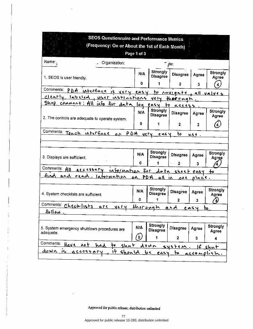
77 Approved for public release 10-285; distribution unlimited

78 Approved for public release 10-285; distribution unlimited

79 Approved for public release 10-285; distribution unlimited