applying sedimentological and geophysical techniques for .... 5 issue 1/version-1... · unlike...
TRANSCRIPT

IOSR Journal of Applied Geology and Geophysics (IOSR-JAGG)
e-ISSN: 2321–0990, p-ISSN: 2321–0982.Volume 5, Issue 1 Ver. I (Jan. - Feb. 2017), PP 84-106
www.iosrjournals.org
DOI: 10.9790/0990-05010184106 www.iosrjournals.org 84 | Page
Applying Sedimentological and Geophysical Techniques for
Facies Analysis and Depositional History of July Member
Sandstones, the Northern Area of July Oilfield, Gulf of
Suez – Egypt
Nader El-Gendy1, Ahmed EL-Shishtawy
1, Moataz Kh. Barakat
1 and
Fouad M. Shawaf2
1Geology Department, Faculty of Science, Tanta University, Tanta, 31527, Egypt
2Exploration Department, Geological Operations and Petrophysics Division, GUPCO, Egypt
Abstract: July oilfield is a major normal fault–bounded structural block. It is a multi-reservoir oilfield located
in the central part of the Gulf of Suez. July Member sandstone (Lower Rudeis) is the main reservoir and it was
deposited during the Early Miocene (Burdigalian). July Member sandstone has been studied for the
interpretation of its depositional environment on the basis of the four defining parameters of: facies; lithology,
sedimentary structures, fossil contents and geometry. Petrographic studies of the cored intervals and ditch
cuttings description of the four wells that were used in this study have revealed that July Member sandstone has
the signatures of a shallow marine environment. On the other hand, sedimentary structures were described
along the cored intervals throughout incomplete cycles of Bouma sequence. Sedimentary structures confirmed
rapid and below wave-base deposition. Environmental diagnosis of benthonic and planktonic foraminifera has
detected the paleo-bathymetric zone of deposition to be between outer neritic and upper bathyal (about 200 m).
July Member in the study area is one of the most significant syn-rift sediments; the geometry of the depositional
environment of these sediments was proven to be affected by the episodic growth of normal faults bounding the
area of study. This study attempted to explain the obtained interpretation contrast throughout a suggested re-
deposition scenario of shallow marine sediments as submarine fan turbidities into deeper marine terrain across
the basin floor. The study of the characteristic gamma ray log motifs with the assist of supplementary
components obtained from petrographic studies confirmed the suggested submarine fan model and highlighted
its integration with a submarine channels system.
Keywords: Sedimentological Technique, Geophysical Technique, Depositional History, July Member, July
Oilfield, Gulf of Suez and Egypt
I. Introduction Diagnosis of the depositional environment of the syn-orogenic sediments and understanding the
associated tectonic activities and its effect on the pre-depositional topography can provide an excellent way to
reduce the risks of hydrocarbon exploration. Also, the identification of the nature of communication between
sand bodies assists in better volumetric calculations and enhances the effectiveness of water injection
mechanisms.
The techniques of environmental analysis can most conveniently be discussed under the four defining
parameters of facies: lithology, sedimentary structures, geometry and fossil contents. The lithology of clastic
sediments is a function not only of the environment in which it was deposited but also of its transportation
history and of the type of rock from which it was derived. Fossil content has always been one of the most
significant methods of identifying the depositional environment of sediments. The way in which fossils lived,
behaved towards one another, and influenced and were influenced by their environment is termed paleoecology.
Unlike lithology and fossils, sedimentary structures are undoubtedly generated in place and can never
have been brought in from outside. The overall shape of a sedimentary facies is a function of predepositional
topography, the geomorphology of the depositional environment and its post depositional history[1].
The response of several geophysical logs is indirectly related to sediment grain size. Such logs may
thus be used as vertical grain size profiles. This is a well-established technique that has been widely used in the
oil industry for many years. Accurate diagnosis of the depositional environment using geophysical log motifs
can easily be made when supplementary core and paleontological data are available. In this study we use
lithology, sedimentary structures, fossil content, geometry, and gamma ray log motifs to interpret the
sedimentary characteristics and depositional environment of July Member sandstones in the northern area of
July oilfield (Fig. 1).

Applying Sedimentological and Geophysical Techniques for Facies Analysis and Depositional ..
DOI: 10.9790/0990-05010184106 www.iosrjournals.org 85 | Page
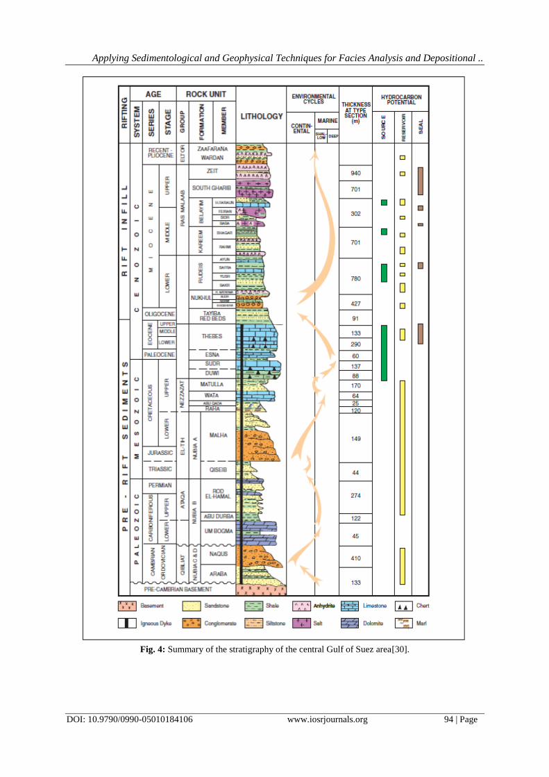
II. Geological setting The July oilfield is situated in the Gulf of Suez, Egypt (Figs. 1 & 2). The 60-80 km. wide, Gulf of Suez,
is the northwest termination of the north northwest trending Red Sea rift. Separation of the African and Arabian
plates along the Red Sea rift was initiated during the Late Eocene to Oligocene [2], but rifting of the Gulf of
Suez did not begin until the Early Miocene (Fig. 3). Rift activity waned in the late Middle Miocene
(Serravallian), the basin became restricted and evaporites were deposited (Figs. 3 & 4).
The geologic setting of the Gulf of Suez is a complex framework, dissected by a number of faults
trending along N–S to NNE–SSW, E–W trending normal faults at the rift borders and within the rift basin and
NE-trending strike-slip faults crossing the Gulf basin [3,4,5,6,7,8,9,10,11,12,13,14,15,16 and 17]. The major
fault systems are mainly related to the tectonic and seismic activity of the Gulf of Suez and Red Sea region[18].
The interaction of these major fault systems resulted in a complex structural pattern consisting of numerous
horsts and grabens with variable relief and dimensions. The Gulf of Suez is subdivided into three structural
provinces according to their structural settings and regional dip directions: the northern Araba dip province (SW
dips), the central BDP (NE dips) and the southern Amal-Zeit dip province (SW dips, Fig. 2).These provinces are
separated by two NE-trending accommodation zones: the Galala-Abu Zenima accommodation zone (GAZAZ)
in the north and the MAZ in the south [16].
Based on surface and subsurface data, the stratigraphic succession of the Gulf of Suez can be
subdivided into three depositional units (Fig. 4). The pre-rift units include Proterozoic basement rocks and
Paleozoic to Upper Eocene sediments. These formations are important as source and reservoir rocks. The Upper
Oligocene and Miocene syn-rift units contain source, reservoir and seal lithologies, as well as volcanic rocks.
The post-rift units are of Pliocene to Pleistocene age. The Miocene rocks are of prime interest as they encounter
three important successions (Asl, Hawara and July Member) which are considered the main oil-bearing
reservoirs in the southern and the central parts of Gulf of Suez. Asl and Hawara formations together with
Mheiherrat Formation are equivalent to Rudeis Formation [19, 20 and 21]. July Member is composed of clastic
lithology (mainly sandstones) in the study area and proved to have prospective sand reservoirs of good
hydrocarbon potentiality.
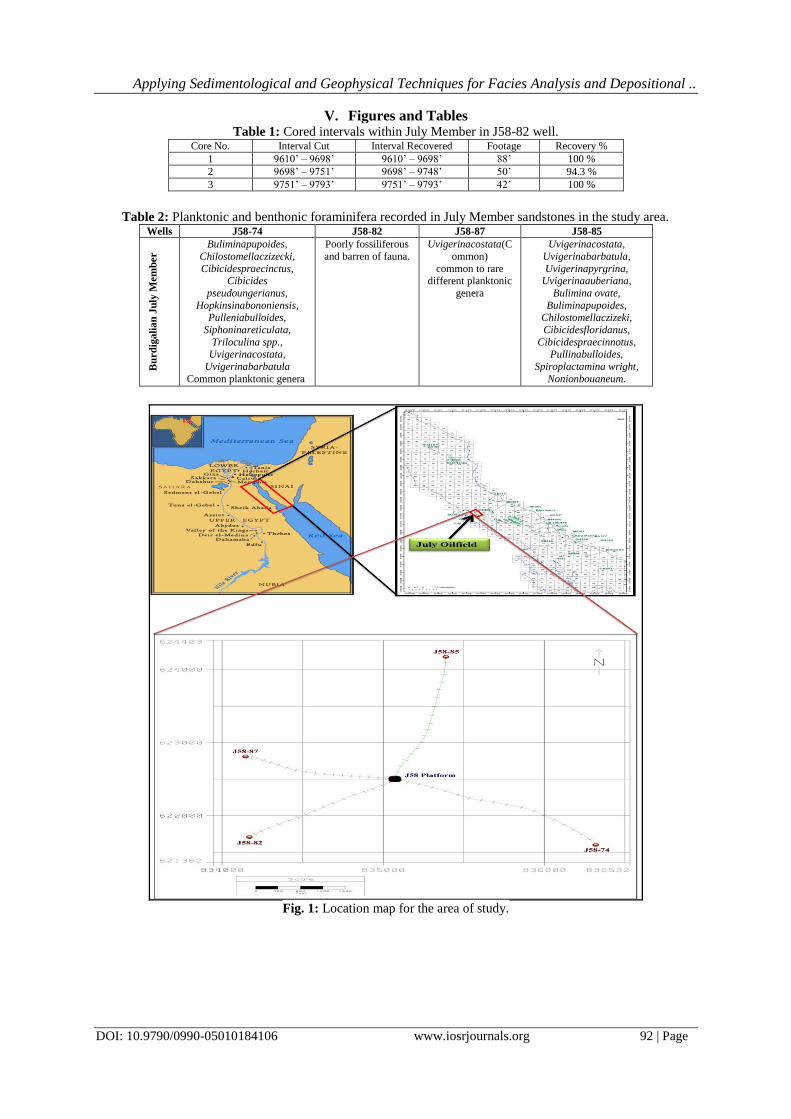
III. Material And Methodology The July oilfield was discovered in 1973 and began full production in1974. One hundred wells have
been drilled within July oilfield by the end of 2014 distributed between exploratory, development and water
injection wells. July-58 platform is located in the northern area of July oilfield. This study is based on the
available data of four selected wells drilled from July-58 platform (J58-74, J58-82, J58-85 and J58-87) (Fig.1).
Data exploited in the study were as the following:
1. Three connected cores representing 33% of the total drilled thickness within July Member sandstones in
J58-82 well with their recorded core gamma ray.
2. Ditch cutting samples of 10 feet interval within July Member in the four selected wells of the study area.
3. The available geophysical logs which were recorded along July Member during drilling the four wells of
the study (Gamma ray, Neutron, Density, Resistivity, dipmeter and Sonic).
4. Bio-stratigraphic logs of the four wells of the study including qualitative data about the foraminiferal
content of July Member sandstones.
5. Composite and mud logs of the four wells of the study area.
Lithological identification and facies analysis of July Member in J58-82 well is based on petrographic
examination of 30 thin sections from core chips and ditch cutting description of the interval that was not cored,
within July Member in this well; together with 4 thin section prepared from selected cuttings representing the
section that was not cored. Thin sections preparation and petrographic study were carried out at the sedimentary
laboratory of the Exploration Department, Gulf of Suez Petroleum Company (GUPCO), Cairo, Egypt. Ditch
cutting samples of 10 feet interval were used to identify and describe the lithology of the July Member in the
other three wells.
Based on the geophysical log responses, July Member in the four wells of the study area was
subdivided into three different zones from bottom to top; zone (A), zone (B) and zone (C); each zone has a
distinctive log pattern. J58-82 is the only well that was cored within July Member section in the northern area of
July oilfield. Three connected cores were collected during drilling this well by Core Laboratories Inc. Interval
cut, interval recovered and recovery percentage of each core are shown in Table (1). In this well, the cored
intervals covered the upper part of zone (A) and the lower part of zone (B), while zone (C) is completely not
included within the collected cores.
Sedimentary structures were described throughout the cored intervals of J58-82 well, and were
represented in the form of repeatable incomplete Bouma sequences. Stratigraphic correlation and well logs
representation were carried out using (Techlog 2011.2.1) software of Schlumberger, in addition of using Canvas

Applying Sedimentological and Geophysical Techniques for Facies Analysis and Depositional ..
DOI: 10.9790/0990-05010184106 www.iosrjournals.org 86 | Page
X software for constructing the schematic profiles and editing the expressive figures of this study. Base map of
the area of study was extracted from (Openworks) application of Landmark.
Environmental diagnosis of different genera of foraminifera was carried out based on the data
contained in the boi-stratigraphic logs of the studied wells. True stratigraphic thicknesses of July Member in the
different wells of the study area were calculated using a special equation which includes dip angles, dip azimuth,
well inclination and well azimuth, besides the measured thicknesses as well.
IV. Results And Discussions The techniques of environmental analysis can most conveniently be discussed under the four defining
parameters of a facies: lithology, sedimentary structures, geometry and fossils. These techniques were applied in
this study on the restrictedly distributed July Member in the northern compartment of July oilfield in order to
interpret its depositional environments. In addition, the use of geophysical wire line logs in subsurface
environmental interpretation is applied in this study.
4.1. Lithology
Petrographic examination and micro-facies analysis were carried out based on the detailed description
of the thin sections of the cored and non-cored intervals of J58-82 well, in addition to description of ditch
cutting samples of the other three wells of the study.
Different zones of July member in well J58-82. Zonation was carried out based on the responses of the
geophysical logs (Fig.5). Zone (A) is the bottom zone in July Member, conformably overlying Nukhul
Formation, and consists of interbedded shale, sandstone and sometimes limestone sequences. The basal part of
zone (A) is a widely distributed shale body known as shale twenty (SH 20), which is correlatable all over the
study area (see the stratigraphic correlation of the northern area of July oilfield, Fig. 21). While zone (B) is the
middle zone of July Member in the study area, and consists mainly of stacked sandstones with minor shale
streaks. The collected cores in this well (J58-82) covered 105’ of this zone and the rest interval (85’) that was
not cored was studied throughout ditch cuttings thin sections and ditch cutting samples of 10’ sampling rate.
Unfortunately, zone (C) was not either partially or completely included in the cored interval of this well; it
consists mainly of sandstone interbedded with minor shale and limestone streaks.
The classification of [22]was followed in this study for the nomenclature of the studied clastic
sediments. Ternary diagrams of the cored Intervals of July Member (in J58-82 well) shown in Figs. (6 & 7) have
revealed that the cored interval of zone (A) ranges from sublithic greywackes to quartz wackes. However, few
samples were classified as sublithic arenites. On the other hand, zone (B) cored interval ranges from sublithic
arenites to quartz arenites, also some samples were described as subfeldspasic arenites and rarely sublithic
greywackes. It deserves to be mentioned that some samples of the cored zone (B) interval was described in a
cyclic manner as coarse siltstones grading to very fine sandstones, besides laminated silty mudstones in some
points.
Compositionally, zone (A) cored interval of July Member in J85-82 well, is characterized by a higher
fine grained matrix content than zone (B) cored interval. Thus, most of zone (A) samples were plotted in the
wackes part of the ternary plot, and the arenites triangle included most of zone (B) samples.
Concerning the components other than matrix and framework which were not taken into consideration
in the classification basis, they are much variable all over the cored interval of both zone (A) and (B). Mica is
occasionally present within the intervals of arenites, especially the samples that was described as subarkoses
(Fig. 8). Macrofossil skeletal fragments are found in both sublithic arenites and sublithic greywackes (Fig.9),
while microfaunal tests are present not only in arenites but also, with much higher percentage, in wackes (Fig.9).
Glauconite is present in all thin sections of the cord intervals (Figs. 10 & 11), and all ditch cutting samples
without exceptions, but with variable percentages. Glauconite is usually found with much high percentage in the
coarse siltstone and laminated silty mudstone intervals. Carbonaceous matter, like glauconite, is distributed all
over the cored interval (Fig.10 a).
Sandstones, which were described in the cored interval of July Member in J58-82 well, contain
numerous calcite rich intervals. Many of these calcite rich intervals are found in relatively finer grained
sandstones. Calcite within these finer grained sandstones consists of detrital calci-micrite or dolo-micrite in few
cases (Fig.11 b); while calcite-rich intervals that are not associated with finer grained sandstones consist mainly
of calci-sparite forming poikilitic texture. Calcite is also present in the form of skeletal fragments or complete
skeletons of foraminifera. Siliceous cementation resulting from overgrowths is also present within the calcite
poor sandstones and intervals of sparry calcite cementation. Siliceous cement is rare in the intervals of
sandstones that are rich in detrital micrite.Fining upward grading shown by a decrease in the clear quartz
material and an increase in the dark color clay in laminated siltstone is recorded from the core ships (Fig. 12).
Figures (13, 14 & 15) are illustrating the vertical distribution of the components that were not
considered in the classification basis in the three cored intervals of July Member in J58-82 well.

Applying Sedimentological and Geophysical Techniques for Facies Analysis and Depositional ..
DOI: 10.9790/0990-05010184106 www.iosrjournals.org 87 | Page
Environmental Diagnosis of Lithology
Almost all sandstone intervals that have been studied either from core or from ditch cuttings, besides
the intervals of laminated siltstones or silty mudstones contain variable percentages of detrital glauconite.
Glauconite is a mineral which is widely believed to be formed only in marine environments and to be very
unstable that it cannot survive reworking. It therefore held to be a diagnostic criterion of marine sediments. In
addition to glauconite, few samples in the studied interval contained minor traces of pyrite.
The marine or most probably shallow marine environment of deposition of July Member sandstones in
the study area may be proven also by the presence of algae and especially phosphatized algae (Fig. 9 c & d).
Phosphatization is a diagnostic process which is most probably characterizing shallow marine environment.
The July Member sandstones were deposited in marine and not continental environment, based on
several evidences such as the abundance of marine foraminifera in the thin sections of studied intervals. Besides
the foraminifera, the studied intervals contained also common macrofossil shell fragments which may indicate
the marine deposition. Sandstones of July Member all over July oilfield are underlain by a relatively thick body
of highly fossiliferous shale (shale 20). The thickness of this shale in the study area ranges from 70’ to 100’.
These shales are rich in marine foraminifera and seem to be deposited in a marine environment.
The main constituents of July Member sandstones are quartz grains together with different types of
rock fragments and feldspars. Feldspars are found either fresh or partially altered and rarely kaolinitized.
Granitic rock fragments, quartz grains, feldspars and mica flakes indicate Precambrian source rock from which
clastics may have been derived. Sedimentary rock fragments may be interformational and the rounded quartz
grains associated with the free kaolinite which was described in the ditch cutting samples may suggest a Nubian
sandstone source as well.
Consequently, the detailed study of the lithology of the July Member in the northern area of July
oilfield proved that we have sediments derived from different sources and accumulated in a marine or
specifically shallow marine environment.
1.1. 4.2. Sedimentary Structures
The study of the sedimentary structures of July Member in the northern area of July oilfield was
established depending on the interval that was cored in J58-82 well. The cored interval was collected to the
surface through three connected cores (Table 1) each of them was investigated and described individually.
Most of the sedimentary structures which were described in this study consisted of inconstant cycles
with repeatable manner and without constant start or end units. The described beds were listed between the
following: normal graded bedding sandstones, massive (structureless) sandstones, plane or parallel laminated
sandstones and laminated siltstones or mudstones.
In addition to the other sedimentary structures which were represented in the core description log, the
four units mentioned above can be treated as incomplete repeatable Bouma sequences. The Bouma sequence
[23], (Figs. 16 & 17) composed of Ta, Tb, Tc, Td, and Te divisions, and always interpreted to be the product of
turbidity current. However, recent core and outcrop studies show that the complete and partial Bouma sequence
can also be interpreted to be a deposit formed by processes other than turbidity currents, such as sandy debris
flows and bottom-current reworking.
Environmental Diagnosis of Sedimentary Structures
According to [24], the Ta division is a deposit of a high-density turbidity current, and the overlying Tb,
Tc and Td divisions are deposits of a low-density turbidity current. In terms of fluid rheology, high-density
turbidity currents are interpreted to represent plastic flows. Also, it was suggested that the term "high-density
turbidity current" is a misnomer, and it may be replaced by the term “sandy debris flows”.
The suite of structures in Bouma sequence has been interpreted in the following way: First, a current
scoured a varity of structures on a mud surface, then, sedimentation of turbidites took place under waning
current conditions. The massive structureless unit (Ta) was deposited with or without normal graded bedding
under an upper flow regime [25 and 26].
[1]Selley stated that the planar or parallel laminated unit (Tb) was deposited by shooting flow and the
micro-cross laminated unit (Tc) was deposited under a lower flow regime. The absence of cross-bedding in the
studied interval of July Member may be related to various causes, such as: flow was too rapid or too thin, or
flow was being very fine-grained. The most logic cause may be that the flow was fast enough to transport sand
in suspension.
The upper laminated siltstone unit (Td) and the most lower part of the silty mudstone unit (Te)
represent the slow settling of silt and clay-sized material in very low flow regime. On the other hand, the upper
part of the homogenous mudstone unit (Te) represents the slow accumulation of mud deposited directly from the
water after the passage of the turbidity current (hemi-pelagic deposition).

Applying Sedimentological and Geophysical Techniques for Facies Analysis and Depositional ..
DOI: 10.9790/0990-05010184106 www.iosrjournals.org 88 | Page
Some of the depositional features that were observed in the cored interval of this study may be related
to rapid deposition and some other features may be related to quite water and below wave base deposition. The
rapid depositional features, such as the common graded bedding, and the flame structure represent the
dewatering mechanism of sediments, in addition to the erosional contacts which are present but difficult to
discern because of relatively uniform sediment size within July Member sandstones. On the other hand, the
absence of wave formed sedimentary structures, such as ripple bedding and cross stratification may be related to
quite water and below wave base conditions.
The above discussion has revealed that the July Member sandstones in the study area have been rapidly
deposited as repeatable cycles of turbidites throughout different density turbidity currents in quiet water below
wave base. The triggering mechanism required for the sediments to be suspended in the turbidity currents may
be provided by the episodic evolution of the normal faults of July oilfield area. July Member sandstones are
synrift-clastics as they were deposited during the rifting activities of the Gulf of Suez. Therefore, the repeated
cycles of turbidites, which were described within the July Member may be related to the intermittent growth of
July oilfield structural elements during the time of deposition.
Environmental diagnosis of lithology confirmed that the July Member sediments have the signature of
a shallow marine environment (i.e. fan delta, barrier bars, etc.). However, the interpretation of the sedimentary
structures is referring to a rapid deposition of sediments throughout turbidity currents in quiet water conditions
below the wave base level. To understand this conflict, the depth of water in which sediments were deposited
was necessary to be investigated using the fossils content.
1.2. 4.3. Fossils Content
In 1994, a project included a detailed paleontological study on the Miocene sediments in the central
part of the Gulf of Suez was carried out in the Gulf of Suez petroleum company (GUPCO). The study included
paleo-ecological and paleo-bathymetric interpretations using different types of foraminifera. The results of this
project were documented in an internal exploration report [27]. In this study of GUPCO, a total of 277 Miocene
samples from five Miocene outcrop sections in Sinai (Nekhiela, Nebwi-3, Gypsum Quarry near Wadi
Gharandal, Wadi Abu Mheiherrat and Wadi Gharandal northwest) were examined for identification of the
different types of foraminifera. It was possible to calculate an average frequency of occurrence of every species
in each paleo-bathymetric zone.
To aid in calibrating the above mentioned paleo-bathymetric zones, a series of samples was obtained
from the sea floor of the Gulf of Suez by having divers scoop of 500 to 1000 grams of surface sediments at the
location of GUPCO’s platforms. As a qualitative analysis of the Miocene foraminifera, a total of 22 wells were
studied in the central Gulf of Suez. Ditch samples were analyzed at 10-foot intervals. This study resulted in the
differentiation of four different paleo-bathymetric zones (Fig. 18).
Foraminiferal fauna in outcrop samples, as well as those in ditch samples, in the studied wells of the
above mentioned study, indicate that the maximum water depths during Nukhul to Kareem time in the central
Gulf of Suez were not much greater than 600 feet and not greater than approximately 1000 feet. The data
obtained from examination of thousands of ditch, core and outcrop samples made it possible to prepare a list of
foraminifera typical of each bathymetric zone.
Environmental Diagnosis of Foraminifera
The Burdigalian Lower Rudeis sandstones which are known as July Member had several common
nomenclatures. The paleontological one is “costata sandstones” relative to the benthonic foraminiferal species
“Uvigerinacostata”. The first downhole appearance of Uvigerinacostata is always considered the
biostratigraphic top of July Member sandstones. However, this index form is not necessary to be found in the
Burdigalianclastics. Absence of this unique form may be due to bad preservation or rapid deposition.
The four wells included in the current study were previously investigated for foraminiferal content in
the interval of July Member sandstones. The results of this investigation were represented in an individual
biostratigraphic log for each well. These logs were studied and its content was simplified in Table (2).
Uvigerinacostata and its foraminiferal assemblage were recorded in all wells of the current study
except for J58-82 well, which is the only well that was cored in July 58 area as mentioned before; the cored
interval in July Member was not investigated for foraminiferal content. The barren interval in J58-82 well may
be rapidly deposited. Uvigerinacostata and the foraminiferal assemblage recorded in July Member interval of
the study area are found distributed within the two lists of foraminifera typical of outer neritic and upper bathyal
paleo-bathymetric zones of the central Gulf of Suez[27].
The above discussion may reveal that July Member sandstones in the northern area of July oilfield
were deposited in a water depth about 200 m (600 feet), in a transition zone between the outer neritic and upper
bathyal zones of the Miocene in the central Gulf of Suez (Fig. 18). In contrast, the environmental diagnosis of
lithology showed that these sediments were accumulated most likely in a shallow marine environment.

Applying Sedimentological and Geophysical Techniques for Facies Analysis and Depositional ..
DOI: 10.9790/0990-05010184106 www.iosrjournals.org 89 | Page
The suggestion that could solve this contrast may be as the following: July Member sediments were
sourced from continental exposures of Precambrian basement rocks and Nubian sandstones, and firstly
accumulated in a shallow marine environment. The accumulation of sediments in a shallow marine environment
may be evidenced by glauconite content and the common macrofossil shell fragments such as mollusks in
addition to the benthonic foraminifera of shallow marine origin e.g. Nonion spp.
After this accumulation of sediments they were re-deposited in a deeper marine environment due to
structurally controlled subsidence which provided a suitable accommodation space for these sediments to be
accumulated. The scenario of re-deposition is also evidenced by the presence of deep marine benthonic
foraminifera such as Uvigerina spp, Chilostomella spp, and Bulimina spp.
1.3. 4.3.Geometry
The overall shape of a sedimentary facies is a function of pre-depositional topography and the
geomorphology of the depositional environment and its post depositional history. Unfortunately, seismic-data
quality in the Gulf of Suez rift, specifically in July oilfield, is too poor to interpret the geometry of the
depositional environments; this is because of multiples created by middle to upper Miocene evaporites. Only by
using data from abundant well control, we can determine the pre-depositional topography and the
geomorphology of the depositional environment.
Structural Evolution
The structural evolution of the July oilfield is a long and extremely complex series of events that began
early in the Pre-Miocene and continued late into the Miocene. The northern July area (July-58) is a tilted fault
block dipping at about twenty degrees to the north east and is bound to the east by the major northwest-southeast
clysmic fault (C1) and to the west by another major clysmic fault (C2) with the same trend. In between the two
main clysmic faults, a series of small faults with the same trend direction. This area is bound to the north and
south by two major transfer elements (T1and T2) almost trending east west (Fig. 19). Both fault groups
controlled the erosion in the Pre Miocene and the deposition in the Miocene and consequently had a great
impact on both the predepositional topography and the geomorphology of the depositional environment of July
Member in the northern area of July oilfield.
Nukhul Formation
The thick overall thickness of Nukhul Formation in the southern area of July oilfield (about 700’) thins
northward to be about 150’ in the northern area. Consequently, the northern area of July oilfield was structurally
high during the early Miocene and the deposition of Nukhul Formation was certainly controlled by the fault (T1)
which separates the northern compartment and the southern area of July oilfield (Fig. 19).The Nukhul Formation
top is lithologically picked at the first limestone bed below the basal shale marker of July Member (Shale 20),
and usually precedes the palaeontologic top by approximately one hundred feet.
July Member
July Member was deposited during the Early Miocene (Burdigalian) as a series of prograding
submarine fan system controlled initially by the tectonic evolution of the field. The deposition of these clastics
occurred throughout turbidity currents at different energies of the flow. These turbidity currents were actively
depositing sands in about 200 meters of water and were fed by a system of feeder channels flowing in from the
western shoulder of the basin.
Although the investigated lithology and textural pattern of July Member sandstones may indicate
various depositional environments such as shelf bars, shoreface deposits and deltas, the deposition in 200 m
water depth and the presence of rapid deposition and below wave-base features are indicator points of
prograditional lobes within a submarine fan system.
The sands of July Member exceed 1000’ in some wells in the southern July oilfield area, but gradually
thin eastwards and northwards to be about 350’ in the northern area of July in J58-85 well. So, by Ramadan
field (about 6 Kilometres east of July oilfield) there are only laterally equivalent basinal shales and carbonates.
These sands are known to be laterally equivalent to July Member sand both from electric log markers above and
below the sand and by the diagnostic presence of the foraminiferal species Uvariginacostata.
The lateral transition of July Member sandstones in July oilfield into the equivalent basinal shales and
carbonates in Ramadan oilfield can be considered as an excellent indication that the July Member sandstones
were sourced from the western shoulder of the rift basin. The distribution of the sands is also influenced locally
by the underlying topography at the close of Nukhul deposition. Structural highs and active fault controlled lows
modified the sand distribution. Again, the southern active "T1" transfer fault was controlling the deposition of
July Member sandstones (Fig. 20).

Applying Sedimentological and Geophysical Techniques for Facies Analysis and Depositional ..
DOI: 10.9790/0990-05010184106 www.iosrjournals.org 90 | Page
Actually, T1 fault was not the main structural element controlling the deposition of July Member in the
northern area of July oilfield. The clysmic faults C1 and C2 were the main structural controllers of
sedimentation processes. As they were active during July Member deposition, the episodic growth of these rift
trend normal faults provided not only the triggering mechanism which activate the sediment moving but also the
accommodation space required for the sediment to be deposited.
Stratigraphic Correlation
Correlation within the July Member has always been difficult and somewhat controversial mainly due
to the massive nature of the sand and the absence of consistent markers. The internal details of the gamma ray
log of July Member interval in the study area can be used to subdivide this interval into three different zones,
named from bottom to top zone A, zone B and zone C (Fig. 21).
Depositional History and Re-deposition Scenario
By the end of Nukhul deposition, a tectonically quite period gave chance to the basal shale body of July
Member (Shale 20) to be deposited at the basin floor as pelagic mud. Shale 20 has almost homogenous
thicknesses all over the study area, except in J58-87 well where the basal part of this pelagic shale body was
faulted out.
Simultaneously, or may be after the deposition of the Shale 20, the accumulation of variable sizes of
terragenous sediments on the shallow portion of the basin was taking place causing the formation of a steeply
sloping pile of waterlogged sediments. These terragenous sediments were sourced from the western shoulder of
the Gulf of Suez rift basin, basically derived from granitic Precambrian basement rocks and Nubian sandstone
sources through a system of channels perpendicular to the basin. The deposition of the sediments in such
shallow marine terrain was either in the form of shore face deposits or shelf bars, or even fan delta.
Actually, in such continental shelves of a rift basin like the Gulf of Suez rift basin, every now and then,
the slope becomes so unstable that a triggering mechanism such as earthquakes or storms causes the sediment
moving from this shallow marine terrain into deeper marine environment.
The triggering mechanism in this model was the discontinuous episodic growth of the normal faults
bounding the study area. The growth of these structural elements gradually increased the basin water depth and
caused the slope to be steeper in addition to activating the sediments to be more and more liquefied until the
mixture assumed the characteristics of turbidity current. This means that the sediments were suspended into a
muddy liquid whose density was greater than that of the surrounding water.
From the petrographic studies which were carried out on July Member in the study area, it was clear
that the sediments remained enough periods in the shallow marine portion of the basin to take its characteristic
features. Sediments after that moved down slope in the form of high density turbidity current under the effect of
gravity beneath the clear water. The presence of some interformational sedimentary rock fragments may indicate
that this turbidity current became erosive on the steep slope. When the current reached the level of the open sea,
its velocity started to diminish.
Deposition then took place, first of the coarsest sediments, and, as the current was waning, of finer and
finer grades. When the velocity of the current returned to zero, pelagic shale deposition had continued out of
suspension as before (deposition of Shale 20).
The above discussion represents the suggested scenario of the re-deposition of a single cycle of
turbidites in a prograding submarine fan across the basin floor. The result is a graded bed of sediments on a
scoured surface. The distance that the turbidity current had moved was not too long to completely deform the
characteristic features of the shallow marine environment which are still preserved after suspension on the
turbidity current and re-deposition. The investigated thin sections of the cored intervals of J58-82 well contained
not only fresh detrital glauconite but also fresh angular feldspar fragments, besides the samples that showed the
partially reworked, pale-colored glauconite and the partially altered feldspars (Fig. 22).
July Member consisted of a series of incomplete turbidite sequences. These turbidite sequences are
mostly incomplete because of the overlapping between the alternative turbidity currents i.e.; when one turbidity
current was depositing its suspended load of sediments, another similar event activated another load of
sediments in a new turbidity current, and the two currents overlapped to generate a new one load. This
suggestion explains the common incomplete Bouma sequences which were described within the cored intervals
of J58-82 well.
1.4. 4.5. Interpretation of the Depositional Environment Using Gamma Ray Log Patterns
The two logs which are mainly used as grain size profiles are the Spontaneous Potential and Gamma
logs due to data shortage; the interpretation of the vertical grain size profiles of July Member in the study area
was dependent basically on the gamma ray logs, where there are no S.P logs were recorded in the four wells of
this study.

Applying Sedimentological and Geophysical Techniques for Facies Analysis and Depositional ..
DOI: 10.9790/0990-05010184106 www.iosrjournals.org 91 | Page
While it is true that clastic environments deposit characteristic grain size profiles, yet no environment
possesses a unique gamma ray log shape. Similar patterns are given by different environments. For this reason,
geophysical log patterns must never be interpreted in isolation. Accurate diagnosis of the depositional
environment can easily be made where supplementary core and paleontological data are available. Where these
are absent or inconclusive, the presence of glauconite, shell fragments, mica and carbonaceous matter can be
used to assist in the correct identification of log patterns.
Common Gamma Ray Log Motifs
Figure (23) shows some of the characteristic gamma ray log motifs which can commonly be seen.
These, from left to right, can be interpreted as following: Thinly interbedded sand and shale, a sand body with a
gradational base and abrupt top (i.e. with an upward – coarsening profile), a uniform sand body with abrupt
upper and lower contacts and a sand body with an abrupt base and a gradational top (i.e. with an upward – fining
profile).Figure (24) shows how the log motifs, which are non-diagnostic on their own, can be allocated to
specific environments when data are available on the presence or absence of glauconite, shell debris,
carbonaceous matter and mica.
July Member Characteristic Gamma Ray Log Motifs
The characteristic gamma ray log motifs of July Member in the study area were investigated to ensure
the interpretation of its depositional environment and were carried out through lithology, sedimentary structures,
fossils and geometry. As it was discussed, the study of the gamma ray log motifs must not be carried out in
isolation. The combination with the study of petrography can be very useful in the detection of sand body
environments. This study proved that July Member sandstones have been deposited as repeated cycles of
submarine fan turbidites across the basin floor in approximately 200 m of water depth. Careful and detailed
investigation of the gamma ray logs, which were recorded within July Member in the four wells of this study
(Fig. 25), have indicated the following:
Zone (A) starts from bottom to top by a consistent high gamma ray pattern represent the characteristic
Shale 20. These shales contain variety of pelagic foraminifera and have approximately homogeneous thickness
all over the study area. The deposition of this shale probably occurred in quite water conditions within water
depth less than 200 m above the basin floor and before the growth activities of the normal faults bounding the
study area.Pelagic shale twenty is followed by a nervous log pattern indicating the thinly interbedded sands and
shales. The cored interval of this zone is glauconitic, occasionally with shell fragments, occasionally micaceous
and with carbonaceous matter. This characteristic log pattern with its specific petrographic components can be
interpreted as prograding lops of turbidites in a submarine fan.
Zone (B) consists of relatively clean gamma ray patterns represents tacked sand bodies with abrupt
upper and lower limits. Petrographic investigation of the cored interval within zone B has showed that these
sandstones contain not only glauconite and shell fragments but also carbonaceous matter and mica. This
characteristic log motif with its core supplementary components can be interpreted as submarine channels acting
as feeders for submarine fan at its basin ward mouth. According to gamma ray log response, the thicknesses and
numbers of the channels that were penetrated in each well is different from one to another (Fig. 25).
The absence of cross bedding suggests that these sandstones may not have been deposited by traction
currents. Their massive nature, together with the presence of occasional scattered clasts (Fig. 16), suggests that
they may have been deposited by channelized grain flows. No doubt that, after the deposition of zone A
turbidites, the slope became more gentle, and the area subsisted a tectonically quite period which gave a chance
to the basin feeders to advance towards the basin floor in the form of submarine channels system cutting across
the basal submarine fans of zone A. The suggestion that zone B is submarine channels system explains the
horizontal communication problems between sand bodies of zone B in the study area as each channel has its
own geometry.
Zone C is characterized by a relatively less nervous gamma ray log patterns than those of zone A.
Ditch cuttings description indicated the presence of glauconite within the sandstones of this zone. There is no
indication for the presence of either mica or shell fragments. But, if we supposed that this zone has almost the
same gamma ray log response as of zone A, then, it may be interpreted as submarine turbidites also. This zone
may be started deposition by the beginning of another cycle of structural overgrowths during the rift activities.
The approximately correlatable pattern of gamma rays within zone C may support the scenario of prograding
lobes of turbidites within a submarine fan.In J58-74 well (Fig. 25), the red arrow is referring to a coarsening-
upward profile while the blue arrow in J58-82 well is referring to a fining-upward profile. This is probably
reflecting the gradual infilling of a channel if it contains mica and/or carbonaceous matter, or may be a
submarine channel if these components were present with glauconite and/or shell fragments. Actually, the
vertical resolution of gamma rays recorded in the four wells of the study area was rarely sufficient to show
individual graded beds of July Member sandstones.
Applying Sedimentological and Geophysical Techniques for Facies Analysis and Depositional ..
DOI: 10.9790/0990-05010184106 www.iosrjournals.org 92 | Page
V. Figures and Tables Table 1: Cored intervals within July Member in J58-82 well.
Core No. Interval Cut Interval Recovered Footage Recovery %
1 9610’ – 9698’ 9610’ – 9698’ 88’ 100 %
2 9698’ – 9751’ 9698’ – 9748’ 50’ 94.3 %
3 9751’ – 9793’ 9751’ – 9793’ 42’ 100 %
Table 2: Planktonic and benthonic foraminifera recorded in July Member sandstones in the study area.
Wells J58-74 J58-82 J58-87 J58-85
Bu
rd
iga
lia
n J
uly
Mem
ber
Buliminapupoides,
Chilostomellaczizecki,
Cibicidespraecinctus, Cibicides
pseudoungerianus,
Hopkinsinabononiensis, Pulleniabulloides,
Siphoninareticulata,
Triloculina spp., Uvigerinacostata,
Uvigerinabarbatula
Common planktonic genera
Poorly fossiliferous
and barren of fauna.
Uvigerinacostata(C
ommon)
common to rare different planktonic
genera
Uvigerinacostata,
Uvigerinabarbatula,
Uvigerinapyrgrina, Uvigerinaauberiana,
Bulimina ovate,
Buliminapupoides, Chilostomellaczizeki,
Cibicidesfloridanus,
Cibicidespraecinnotus, Pullinabulloides,
Spiroplactamina wright,
Nonionbouaneum.
Fig. 1: Location map for the area of study.

Applying Sedimentological and Geophysical Techniques for Facies Analysis and Depositional ..
DOI: 10.9790/0990-05010184106 www.iosrjournals.org 93 | Page
Fig.2: Tectonic elements of the Gulf of Suez, showing the location of July oilfield [Modified after 28].
Fig. 3: Structural cross section through the Gulf of Suez [after 29].
Applying Sedimentological and Geophysical Techniques for Facies Analysis and Depositional ..
DOI: 10.9790/0990-05010184106 www.iosrjournals.org 94 | Page
Fig. 4: Summary of the stratigraphy of the central Gulf of Suez area[30].

Applying Sedimentological and Geophysical Techniques for Facies Analysis and Depositional ..
DOI: 10.9790/0990-05010184106 www.iosrjournals.org 95 | Page
Fig. 5: Different zones of July member in well J58-82. Zonation was carried out based on the responses of the
geophysical logs.
CORE

Applying Sedimentological and Geophysical Techniques for Facies Analysis and Depositional ..
DOI: 10.9790/0990-05010184106 www.iosrjournals.org 96 | Page
Fig. 6: Ternary plot showing detrital composition of July member sandstones which contain less than 15% of
fine grained matrix (arenites), based on point counts (300 counts per sample) conducted on thin sections taken
from the cores of J58-82 well. Q = quartz (monocrystalline and polycrystalline); F = all feldspars; L=
sedimentary, igneous, and metamorphic lithic fragments and chert. See Figure (1) for the location of the well,
Figures (14), (15) and (16) for the location of thin sections in the core.
Fig. 7: Ternary plot showing detrital composition of July member sandstones which contain more than 15% of
fine grained matrix (wackes), based on point counts (300 counts per sample) conducted on thin sections taken
from the cores of J58-82 well. Q = quartz (monocrystalline and polycrystalline); F = all feldspars; L =
sedimentary, igneous, and metamorphic lithic fragments and chert.

Applying Sedimentological and Geophysical Techniques for Facies Analysis and Depositional ..
DOI: 10.9790/0990-05010184106 www.iosrjournals.org 97 | Page
Fig.8: Core chips thin sections photomicrographs. (a) Very low percentage of fine grained matrix in quartz
arenite, plane polarized light: magnification 40X, at depth 9759.5’, from well J58-82. (b) High percentage of
fine grained matrix in quartz wacke, plane polarized light: magnification 40X, at depth 9767.5’, from well J58-
82. (c) High interference colors of a mica flack, cross polarized light: magnification 100X, at depth 9757’, from
well J58-82(d) Different types of rock fragments in sublithic greywacke, cross polarized light: magnification
40X, at depth 9741’, from well J58-82.
Fig.9: Core chips thin sections photomicrographs. (a) Highly fossiliferous sublithic greywacke, plane polarized
light: magnification 200X, at depth 9725’, from well J58-82.(b) Very coarse to granule size calcareous shell
fragment, cross polarized light: magnification 40X, at depth 9736’, from well J58-82.(c) & (d) Phosphatized
algae in sublithicarenite, (c) in plane polarized light & (d) in cross polarized light: magnification 40X, at depth
9645.5’, from well J58-82.

Applying Sedimentological and Geophysical Techniques for Facies Analysis and Depositional ..
DOI: 10.9790/0990-05010184106 www.iosrjournals.org 98 | Page
Fig.10: Core chips thin sections photomicrographs. (a) Well sorted, glauconitic very fine sandstone rich in
carbonaceous matter, plane polarized light: magnification 40X, at depth 9683.5’, from well J58-82. (b) Coarse
siltstone with fine grains calci-micrite and argillaceous matrix, cross polarized light: magnification 40X, at
depth 9683.5’, from well J58-82.(c) Inter-formational glauconitic, fine sandstone, sedimentary rock fragment in
sublithic to lithic arenite, plane polarized light: magnification 40X, at depth 9654.5’, from well J58-82. (d) Intra-
formational very coarse plagioclase fragment in sublithic to lithic arenite, cross polarized light: magnification
40X, at depth 9654.5’, from well J58-82.
Fig. 11: Core chips thin sections photomicrographs. (a) Detrital glauconite in sublithicarenite, plane polarized
light: magnification 40X, at depth 9648’, from well J58-82. (b) Very fine dolomicrite matrix in sublithicarenite,
cross polarized light: magnification 200X, at depth 9736.5’, from well J58-82.(c) Pebble size rock fragment in
poorly sorted sublithicarenite, cross polarized light: magnification 40X, at depth 9699.5’, from well J58-82. (d)
Granule size quartz grain in sublithicarenite, plane polarized light: magnification 40X, at depth 9699.5’, from
well J58-82.

Applying Sedimentological and Geophysical Techniques for Facies Analysis and Depositional ..
DOI: 10.9790/0990-05010184106 www.iosrjournals.org 99 | Page
Fig.12: Core chips thin sections photomicrographs. (a) & (b) Fining upward grading shown by a decrease in the
clear quartz material and an increase in the dark color clay in laminated siltstone, (a) in plane polarized light, (b)
in cross polarized light: magnification 40X, at depth 9693’, from well J58-82. (c) & (d) Clay lamina rich in
microfauna in laminated siltstone, plane polarized light: magnification 40X, at depth 9693’, from well J58-82.
Fig. 13: Core Description and Facies Analysis Log representing the interval from 9610’ to 9698’ within July
member in J58-82 well. Ta-e representing Bouma sequence unites from A to E. Horizontal arrows are referring
to the depths of the thin sections that have been studied. See Figure (1) for the location of the well.

Applying Sedimentological and Geophysical Techniques for Facies Analysis and Depositional ..
DOI: 10.9790/0990-05010184106 www.iosrjournals.org 100 | Page
Fig.14: Core Description and Facies Analysis Log for core # 2 representing the interval from 9698’ to 9748’
within July member in J58-82 well. Ta-e representing Bouma sequence unites from A to E. Horizontal arrows
are referring to the depths of the thin sections that have been studied. See Figure (1) for the location of the well.
Fig. 15: Core Description and Facies Analysis Log for core # 3 representing the interval from 9751’ to 9793’
within July member in J58-82 well. Ta-e representing Bouma sequence unites from A to E. Horizontal arrows
are referring to the depths of the thin sections that have been studied. See Figure (1) for the location of the well.

Applying Sedimentological and Geophysical Techniques for Facies Analysis and Depositional ..
DOI: 10.9790/0990-05010184106 www.iosrjournals.org 101 | Page
Fig.16: Core photograph within core one interval of July member sandstones in J58-82 well. A= calcite rich
lamina, B= large size calcite nodule, and C= small size calcite nodule or may be macrofossil shell fragment. Ta,
Tb and Td are referring to unit A, B and D of Bouma sequence. Depths and scale are shown within the
photograph which was taken by Core Laboratories Inc.
Fig.17:The turbidite facies model (the Bouma Sequence) showing Ta, Tb, Tc, Td, and Te divisions [after 31].
Fig.18: Schematic profile showing limits of the depositional environments of Miocene sediments in the central
Gulf of Suez.

Applying Sedimentological and Geophysical Techniques for Facies Analysis and Depositional ..
DOI: 10.9790/0990-05010184106 www.iosrjournals.org 102 | Page
Fig.19: July Member structure contour map showing the locations of the four wells used in this study [27].
Fig.20: Schematic profile showing the structural evolution and its effect on the geometry of the depositional
environment of Early Miocene sediments (Nukhul formation and July Member) in the northern area of July
oilfield.

Applying Sedimentological and Geophysical Techniques for Facies Analysis and Depositional ..
DOI: 10.9790/0990-05010184106 www.iosrjournals.org 103 | Page
Fig. 21: Stratigraphic correlation of July member in the northern area of July oilfield. The true stratigraphic
thickness of July member is decreasing to the north. The correlation is referenced to the base of shale 20 or to
the lithological top of Nukhul as a datum. The logs are calibrated to the true stratigraphic thickness are not
spaced proportionally to the distances between wells.
Fig.22: Schematic profile showing the re-deposition scenario of July Member turbidites as a prograding
submarine fan across the basin floor influenced by the structural growth in the study area.

Applying Sedimentological and Geophysical Techniques for Facies Analysis and Depositional ..
DOI: 10.9790/0990-05010184106 www.iosrjournals.org 104 | Page
Fig.23: Four characteristic gamma log motifs and the possible environmental interpretations [redraw after 1].
Fig.24: The effect of the presence or absence of glauconite, shell debris, carbonaceous matter and mica on the
sands environmental diagnosis [modified after 1].

Applying Sedimentological and Geophysical Techniques for Facies Analysis and Depositional ..
DOI: 10.9790/0990-05010184106 www.iosrjournals.org 105 | Page
Fig. 25: Characteristic gamma ray log motifs of July Member sandstones in the study area, representing the
most probable environmental interpretations. Glauconite description was carried out using core thin sections and
ditch cutting of the non-cored intervals, other constituents were recorded in the core thin sections only. Logs
were calibrated to their true stratigraphic thicknesses.
VI. Conclusions Environmental diagnosis of the lithological studies that were carried out on July Member sandstones
showed unique signatures for a probable shallow marine environment; e.g. sand bars, barrier islands, shoal
sands, fan delta, etc. Sedimentary structures were described along the available cores as incomplete cycles of
Bouma sequence which is a standard sequence of sedimentary structures for deposits of turbidity currents. Also,
some sedimentary features indicated the rapid deposition of sediments in quiet water below the wave base level.
This is opposite to the shallow marine interpretation obtained from petrography. This conflict was overcome
throughout the foraminiferal paleo-pathymetric studies on July Member sediments. These studies indicated that
July Member sandstones were deposited in approximately 200 m of water depth in a transition zone between
outer neritic and upper bathyal paleo-bathymetric zones of the Miocene in the central Gulf of Suez.
The obtained results were tied with structural evolution of the study area and introduce a suggested re-
deposition scenario which explain the depositional history of July Member sediments and how the deposition of
these sediments was completely controlled by the episodic growth of the normal faults bounding the area of
study. The syn-rift sediments of July Member were sourced from the western shoulder of the Gulf of Suez rift

Applying Sedimentological and Geophysical Techniques for Facies Analysis and Depositional ..
DOI: 10.9790/0990-05010184106 www.iosrjournals.org 106 | Page
basin and accumulated initially in a shallow marine environment. The intermittent movement of the western
fault provided the triggering mechanism for these sediments to be suspended in turbidity currents, and created
additional accommodation space for the sediments to be re-deposited into deeper marine environment across
steeper slope as incomplete cycles of submarine fan turbidites.
After that, the area subsisted a quiet period of tectonic activities which gave chance to a submarine
channels system to be developed across the basal submarine turbidites. This was indicated by the study of the
characteristic gamma ray log motifs. Then, another cycle of structural overgrowths were taken place and
consequently another cycle of turbidites were deposited representing the upper submarine fan of July Member
sandstones.
References [1]. Selly, R.C., Ancient sedimentary environments: Cornell University press, (3rd Ed.) 1984, pp. 7-26, 252-253 & 260-271.
[2]. Pivnic, D., M. Ramzy, B.L. Steer, J. Thorseth, Z. El Sisi, I. Gaafar, J.D. Garing, and Tucker, R.S., Episodic growth of normal faults as recorded by syntectonic sediments, July oil field, Suez rift, Egypt, AAPG Bulletin, v. 87, 2003, pp. 1015-1030.
[3]. ABD EL-GAWAD, M., The Gulf of Suez: a brief review of stratigraphy and structure: Phil. Trans. Roy. Soc. London A267: 1970,
pp.41–48. [4]. Bobbit, J.E. and Gallagher, J.D., The petroleum geology of the Gulf of Suez: Tenth Annual Offshore Technical Conference,
Houston, Texas, 1978, pp. 375–380.
[5]. Khalil, B.A., Geological and sedimentological studies of Oligo-Miocene section in Abu Zenima area and October Field. M.Sc.
Thesis, Geology Department, Ain Shams University, Cairo. 1984, p.284.
[6]. Shahin, A.N., Shehab, M.M., Petroleum generation, migration and accumulation in the Gulf of Suez offshore, Sinai, vol 1. 6 thEGPC
Exploration Seminar, Egypt, 1984, pp. 126–152. [7]. Hagras, M., Some geological observation in the Gulf of Suez area, Egypt: 8th EGPC Exploration Conference, Cairo, 1986.
[8]. Mesheref, W.M., Rafel, E.M. and Abdel Baki, S.H., Structural interpretation of the Gulf of Suez and its oil potentialities: 3rd EGPC
Exploration Seminar, Cairo, 1976. [9]. Hataba, H., Hosny, W. and Gaafar, I., Application of graphic technique on the Miocene stratigraphy in October field area, Gulf of
Suez: 10thEGPC Conference, Cairo, 1990, pp 320–344.
[10]. Rashed, A., The main fault trends in the Gulf of Suez and their role in oil entrapment: 10thEGPC Conference, Cairo, 1990, pp 43–178.
[11]. Shahin, A.N., Oil window in the Gulf of Suez and the Northern Red Sea area: 1stInternational Symposium on Sedimentation and
Rifting the Red Sea and Gulf of Aden, Egypt,1992. [12]. Hassouba, A., Sarrawi, M., and Sakr, S., Early syn-rift sedimentation in October field area: a stratigraphic model for hydrocarbon
accumulation: 12thEGPC Conference, Cairo, 1994, pp 341–350.
[13]. Shahin, N.A., Hassouba, A., and Sharaf, L.M., Assessment of petroleum potential in the Northern Gulf of Suez. Twelfth Petroleum Exploration and Production Conference, Cairo, 1994, Part I of II, pp 152–174.
[14]. Barakat, M. Kh., Petrophysical and seismic studies on the Lower Miocene rocks in Abu Rudeis area, Gulf of Suez, Egypt, M.Sc.
Thesis at Tanta University, Tanta, Egypt, 216 p., 2003. [15]. Lashin, A. and Abd El-Aal, M., Seismic data analysis to detect the depositional process environments and structural framework of
the east central part of Gharib Province, Gulf of Suez-Egypt: Annals of the Egyptian Geological Survey 27: 2004,pp.523–550.
[16]. Abd El-Naby, A., Abd El-Aal, M., Kuss, J., Boukharay, M., and Lashin, A., Structural and basin evolution in Miocene time, Southwestern Gulf of Suez, Egypt: Neues Jahrbuchfür Geologie und Paläontologie-Abhandlungen, Germany 251(3): 2009, pp.331–
353.
[17]. Abd El-Naby, A., Abd El-Aal, M., Kuss, J.,and Boukharay, M., Stratigraphy interpretation of structurally controlled deposition: Middle Miocene Kareem Formation, southwestern Gulf of Suez, Egypt; GeoArabia 15(3): 2010, pp.129–150.
[18]. Al-Arifi, N., Lashin, A., AL-HUMIDAN S., Migration of local earthquakes in the Gulf of Aqaba, Saudi Arabia: Earth Sci. Res SJ16
(1): 2012, pp.35–40. [19]. Lashin, A., Al-Arifi, N.,Abu Ashour, N., Evaluation of the ASL and Hawara Formations using seismic- and log-derived properties,
October oilfield, Gulf of Suez, Egypt: Arab J Geosci. 3–4: 2011, pp. 365–383. [20]. Lashin, A., and Mogren, S., Total organic carbon enrichment and source rock evaluation of the Lower Miocene rocks based on well
logs: October oilfield, Gulf of Suez-Egypt: Int. J. Geosci. 3: 2012, pp.683–695.
[21]. Lashin, A., and Serag El-Din,S., Reservoir parameters determination using artificial neural networks: Ras Fanar field, Gulf of Suez, Egypt: Arab J. Geosci.doi:10.1007/s12517-012-0541-6,2012,pp. 2789-2806.
[22]. Pettijohn, F.J., Potter, P.E. and Siever, R., Sand and sandstone. 2nd edition, New York, 553 p., 1987.
[23]. Bouma, A.H., Sedimentology of some Flysch Deposits: A Graphic Approach to Facies Interpretation: Elsevier, Amsterdam, 168 p., 1962.
[24]. Lower, D.R., Sediment gravity flows, Depositional models with special reference to the deposits of high-density turbidity currents:
J. Sediment. Petrol. 52, 1982, pp. 279-297. [25]. Walker, R.G., The origin and significance of the internal sedimentary structures of turbidites: Proc. Yorkshire Geol. Sot. 35, 1965,
pp. l-32.
[26]. Harms, J.C., and Fahnestock, R.K., Primary sedimentary structures and their hydrodynamic interpretation: Middleton, G.V. (Ed.),
1965, pp. 84-115.
[27]. Internal report, Paleo-environments and depositional history of the Miocene clastics within the central Gulf of Suez: Gulf of Suez
petroleum Company (GUPCO), Maadi-Cairo, Egypt, ER 84-68 (GS), 1994. [28]. Khalil, S., and McClay, K., Structural architecture of the Eastern Margin of the Gulf of Suez: field studies and analogue modelling
results. 14thEGPC Conference, Cairo, 1998, pp. 201-211.
[29]. Evans, A.L., Miocene sandstone provenance relations in the Gulf of Suez: Insights into syn-rift and uplift history, AAPG Bull., 74, 1990, pp. 1386-1400.
[30]. Alsharhan, A. S., and M. G. Salah, Geology and hydrocarbon habitat in rift setting: northern and central Gulf of Suez, Egypt:
Bulletin of Canadian Petroleum Geology, v. (43) 2, 1995, pp. 156–176. [31]. Shanmugam, G., The Bouma sequence and the turbidite mind set: Mobil Technology Company, 1997, pp. 203-209.