applied thermal engineering - sfu.cambahrami/pdf/2018/a pressure drop study for packed bed... ·...
TRANSCRIPT
Contents lists available at ScienceDirect
Applied Thermal Engineering
journal homepage: www.elsevier.com/locate/apthermeng
Research Paper
A pressure drop study for packed bed adsorption thermal energy storage
Behzad Baghapour, Mina Rouhani, Amir Sharafian, Sahand Behboodi Kalhori, Majid Bahrami⁎
Laboratory for Alternative Energy Conversion (LAEC), School of Mechatronic Systems Engineering, Simon Fraser University, BC V3T 0A3, Canada
H I G H L I G H T S
• Experimental and modeling study is performed on pressure drop inside adsorber beds.
• The model covers a wide range of porosity, from low to high permeability medium.
• A modified permeability is defined to consider inertial effects.
• The experiment reveals negligible effect of water uptake on pressure drop.
• The model shows slight change in pressure drop due to heat of adsorption.
A R T I C L E I N F O
Keywords:Pressure dropAdsorption packed bedInertial effectModified permeabilityThermal energy storage
A B S T R A C T
Adsorption thermal energy storage has received considerable attention as it can overcome the mismatch betweensupply and demand of renewables, providing high energy storage per volume. In the packed bed adsorptionthermal energy storage, pressure drop is of key concern since higher pressure drop leads into lower energystorage efficiency. In this paper, an experimental and modeling investigation on the pressure drop inside theadsorption packed beds is performed. An accurate semi-analytical closed-form relationship is proposed to cal-culate the pressure drop inside a column of adsorbent materials, taking into account the Laplacian friction, aswell as the inertial effects. The model covers a wide range of porosity, between low-permeability medium, adense packed bed of spherical particles, and high-permeability media, a pure viscous fluid. A modified per-meability is defined to consider the inertial effect for a moderate range of the particle Reynolds number(0 < Rep < 300). An experimental apparatus is designed for measuring the pressure drop for different bed sizesand inlet air velocities. The proposed model shows good agreement with the experimental data with the relativedifference of 7.6% at 0.73m/s for silica gel and 15.3% at 0.84m/s for zeolite 4A packed beds. The experimentreveals that the effect of water uptake on the pressure drop of packed bed with wet adsorbent is negligible in thetested particle Reynolds number range, with a relative difference of less than 1.0% compared to dry adsorbentfor 18–30 cm long columns. The proposed formula for pressure drop, consequently, can be applicable for wetadsorbents regardless of the water uptake amount, with a good level of accuracy. Moreover, the analytical modelshows up to±2% change in pressure drop due to heat of adsorption of the tested adsorber columns.
1. Introduction
Packed beds are widely used in various applications such as gaseousmixture drying [1], purification processes [2], dehumidification [3],filtration [4], adsorption cooling systems [5], and thermal energy sto-rage systems [6,7], to name a few. The significant energy consumptionfor overcoming the pressure drop in packed beds, makes the optimaldesign of such systems crucial. Particularly, pressure drop is of greatimportance for energy storage efficiency of the sensible [8], latent [9],and packed bed thermal energy storage (TES) systems [10].
Adsorption TES (ATES) is a promising sustainable, energy efficient
alternative to conventional heating and cooling methods, with a highenergy storage density and insignificant heat loss for long-term storage[11]. Performance of the open ATES highly depends on diffusion ofadsorbate inside the bed, heat transfer, and pressure drop [12–14].High pressure drop in ATES results in the use of electric fans, whichincreases the power consumption, and consequently decreases the en-ergy storage efficiency [15]. This makes detailed study of pressure dropin the adsorber bed and optimum design of the bed crucial to promotewidespread adoption of open ATES.
Empirical correlations for different packing geometries [16–18] aswell as analytical models of linear Darcy flow problems [16] are
https://doi.org/10.1016/j.applthermaleng.2018.03.098Received 3 January 2017; Received in revised form 18 February 2018; Accepted 29 March 2018
⁎ Corresponding author.E-mail address: [email protected] (M. Bahrami).
Applied Thermal Engineering 138 (2018) 731–739
Available online 31 March 20181359-4311/ © 2018 Elsevier Ltd. All rights reserved.
T
available for pressure drop calculations. However, non-linearity of theinertial effects limits the theoretical investigations to the numericalmethods [19]. Although the numerical approaches present comparativeaccurate results for laminar and turbulent flows [20–23], high com-putational costs decrease their applicability for complex designs. Ac-curate analytical model provides an easy-to-use relationship for thepressure drop calculation. The main focus of analytical studies wasmainly on deriving viscous permeability based on the Stokes flow at thepore-scale [24,25]. Brinkman [26] modified the Darcy’s equation byadding the viscous diffusion effect. He showed that the effective visc-osity, in essence, is a function of the fluid dynamic viscosity, and thepacked bed porosity and tortuosity [26]. Neale and Nader [27] devel-oped a permeability correlation using a drag force model over a singleparticle embedded on swarm of particles.
The non-linearity, due to high flow speed, was introduced by Ergunin the pressure drop calculations of packed beds [18]. Moreover, theeffect of porosity variation was taken into account in the pressure dropcalculation of packed beds with low bed-to-particle diameter ratios, by
correcting the Ergun’s equation [28,29].Packed bed thermal energy storage systems have been investigated
by experiments [12,30], lumped element numerical model [31], andcomputational fluid dynamics (CFD) [32]. Complexity of the numericalsimulation of reacting flow [33] can be favorably reduced by usingsemi-analytical approaches for the adsorber packed beds [3,34]. Foradsorption dehumidification application, Finocchiaro et al. [30] foundthat the incoming air temperature has a slight impact on the pressuredrop inside the packed beds. They also showed that the Ergun’s equa-tion could predict pressure drop with about 20% relative difference, forthe flowrate range of 100–500m3/h, while it was less accurate forhigher air flowrates.
In this study, a theoretical-experimental approach is followed tostudy the steady-state axisymmetric fully-developed flow inside thecylindrical adsorption packed beds. A new compact analytical model isdeveloped with consideration of viscous friction, viscous permeability,and the inertial effect, to calculate the pressure drop. A testbed of ad-sorbent is designed and built, and several pressure drop measurements
Nomenclature
A cross-sectional areaC coefficient of the inertial effect (m−1)D Bed’s diameter (m)ESD energy storage densitye, E linearization errordp particle diameter (m)
″fp porous bulk frictionK permeability (m2)∼K modified permeability (m2)H Bed height (m)
PΔ pressure drop (Pa)Q volumetric flow rate (m3/s)Rep particle Reynolds numberRH relative humidityT temperature (°C)u macroscopic fluid velocity (m/s)U0 average velocity (m/s)x r, spatial coordinates (m)wmax maximum water uptake
Greek symbols:
α β, coefficients in modeling porous frictionξ η, non-dimensional spatial coordinatesε porosityρ density of the fluid (kg/m3)μ dynamic viscosity of the fluid (N s/m2)∼μ effective viscosity (N s/m2)τf viscous friction tension (N/m2)λ parameter regarding non-dimensional permeabilityσ pressure-drop scaling factorψ friction factorϕ approximating variable in linearization approachCF cost function (Eq. (31))
Sub/Superscripts:
p Particlef Fluidcv Control volumepf Porous frictionvf Viscous friction∗ Non-dimensional value
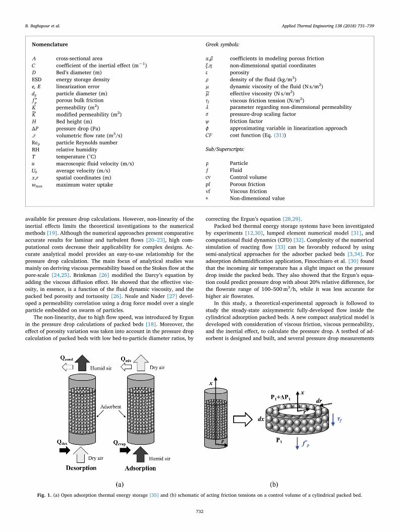
Fig. 1. (a) Open adsorption thermal energy storage [35] and (b) schematic of acting friction tensions on a control volume of a cylindrical packed bed.
B. Baghapour et al. Applied Thermal Engineering 138 (2018) 731–739
732
through the test column are conducted. The effect of uptake on thepressure drop inside the adsorption packed bed is also analyzed. Themodel capability to predict pressured drop in the packed beds with awide range of permeability is examined with the existing experimentaldata. Moreover, the governing equations of a steady-state in-compressible isothermal flow are solved by using CFD and the resultsare compared with the results of the proposed model. good agreementsbetween both experimental and numerical results with the proposedanalytical results have been observed.
2. Open thermal energy storage system
The schematic diagram of an open adsorption TES is shown inFig. 1(a). During charging process, dry hot air passes through an ad-sorber packed bed, leaving the bed cold and humid. After desorption,ATES can remain charged as long as no adsorbate is introduced into thebed. In Adsorption process, bed is discharged by adsorbing water va-pour from cold humid air and releasing heat of adsorption to the air[35]. This heat, which is a combination of the latent and binding heat,can be used for heating purpose.
Freni et al. [36] showed that for adsorption cooling system (ACS),the loose grain packed bed adsorber provides more volumetric powercompared to the coated adsorber bed. In the open ATES systems, energystorage per volume is higher for the packed bed adsorbers . Although,one of the drawbacks of the loose grain adsorption system compared tothe coated adsorber bed is the pressure drop through the packed ad-sorbent materials, which suppresses the adsorbate diffusion [37] andreduces the storage efficiency.
3. Pressure drop model development
A schematic of a cylindrical granular bed and the acting frictiontensions over a representative control volume are shown in Fig. 1(b).The following assumptions are considered:
● The fluid flow is steady-state, laminar, fully-developed, and ax-isymmetric.
● The fluid properties remain constant along the adsorption packedbed.
● Temperature change due to adsorption has negligible effect on thepressure drop.
● The gravity effect is neglected.● The porosity is uniform inside the bed (the effect of confining wall
on the porosity distribution has been neglected in low bed-to-par-ticle diameter ratios [28]).
Using the above assumptions, the force balance on each controlvolume leads to:
= − ″dPdx r
ddr
rτ f1 ( )f p (1)
where the first and second terms on the right-hand side of the equationare the viscous friction acting on the surface of the control volume, andthe porous friction that imposed on the volume, respectively.
Since a fully-developed flow is assumed, the velocity profile is not afunction of the axial direction and the pressure gradient is constantalong the bed. Therefore, the overall pressure drop can be calculatedonly by summing up the pressure drops of all the control volumes.Consequently, the pressure drop of each control volume of unit lengthcan be rewritten as follows:
= +P P P(Δ ) (Δ ) (Δ )cv vf pf (2)
where P(Δ )vf is the pressure loss due to the viscous drag force fromsurrounding fluid on the surface of the control volume and P(Δ )pf is theeffect of porous drag force exerted on the bulk of the control volume.Considering a Newtonian fluid, i.e., = ∼τ μ du dr( / )f , the viscous-drag
term can be formulated as follows:
⎜ ⎟= ⎛⎝
+ ⎞⎠
∼P μ d udr r
dudr
(Δ ) 1vf
2
2 (3)
where ∼μ is the effective dynamic viscosity, defined as =∼μ μ ε/ 1/ for anisotropic porous medium [38].
The porous friction contribution in the pressure drop calculation hastwo main parts: i) a linear viscous permeability term, assuming acreeping flow in the pore-scale, and ii) a nonlinear inertial term due tothe high particle Reynolds numbers. The overall porous friction termhas the following relationship [18]:
= +P αu βu(Δ )pf2 (4)
where α refers to the viscous permeability effect due to the Stokes flowin the void spaces between the particles, and β accounts for the effect ofthe pore-scale local inertia. These coefficients have been formulated viaempirical models for the packed beds. In this study, one famous em-pirical formula, known as Ergun’s equations, is used, which is applic-able to the packed beds with a uniform packing geometry [18]:
≡ =−
αμK
μ εd ε
150 (1 )
p
2
2 3 (5)
≡ =−
βρC ρ ε
d ε21.75 (1 )
p3 (6)
where K is defined as the viscous permeability of porous media, C is theinertial coefficient, and dp is the particle diameter.
3.1. Inertial effect approximation
To deal with the nonlinear inertial effect, a general linearization canbe proposed and validated afterward for moderate flowrates( < <0 Re 300p ).
≡ ≅ + ⩽ ⩽P βu β ϕ U u O u u ϕ U(Δ ) ( ) ( ), where 0vf,inertial2
1 02
2 0 (7)
where U0 is the average velocity calculated from the inlet flowrate di-vided by the packed bed cross-sectional area, i.e., =U Q A/0 . The ap-proximation is sub-linear, when < <ϕ0 11 , and is super-linear, when
>ϕ 11 [39]. The term ϕ2 varies accordingly in the range of < ≤ϕ1 22from a very low permeability to a full viscous flow condition inside thecylinderical packed beds.
To accurately approximate the nonlinear inertial effect by the linearEq. (7), an error analysis is required. The local error, e r( )u , at each pointalong the packed bed cross section can be defined as follows:
≡ −e r u r ϕ U u r( ) ( ) ( )u2
1 0 (8)
By normalizing the local error, one can achieve:
⎜ ⎟ ⎜ ⎟= = ⎛⎝
⎞⎠
− ⎛⎝
⎞⎠
= −e e rU
uU
ϕ uU
u ϕ u: ( )u
u
02
0
2
10
21 (9)
where =u u U/ 0. The global L2 norm of the error in the velocity fieldwill be obtained consequently as:
∫ ⎜ ⎟= = ⎛
⎝+ − ⎞
⎠E ϕ ϕ e du ϕ
ϕ ϕ ϕ ϕ( , ):
5 3 2ϕ
u1 2 02
23 2
212
1 22
(10)
Considering linearization error in the space of approximating vari-ables ϕ ϕ( , )1 2 , the minimized error occurs along =ϕ ϕ3/41 2 for a given ϕ2with ∂ ∂ =E ϕ/ 01 and ∂ ∂ >E ϕ/ 02
12 . A value of ϕ2= 4/3 is selected
within the discussed range of ϕ2, which simplifies the derived formulasto the linear approximation with =ϕ 11 . A parametric study on thelinearization parameters has been performed in Section 6.1.
For an acceptable linear approximation, the maximum norm of erroralong the radial direction should be bounded:
≡ ≡ <∞⩽ ⩽
E e r e r δ δ|| ( )|| max | ( )| , where is finite.ur R
u0 (11)
B. Baghapour et al. Applied Thermal Engineering 138 (2018) 731–739
733

Using Eq. (8) with =ϕ 11 , the maximum error occurs at rm, where=u r U( ) /2m 0 . Substituting u r( )m into Eq. (8), the maximum error is
obtained:
≡ ⩽ ≈∞E e rU
O U|| ( )||4
( )u02
02
(12)
Eq. (12) reveals that, in order to maintain the order of magnitude ofthe maximum error below unity, the average velocity should be
≤ ≤U0 10 , which is a valid assumption for the packed beds withmoderate inlet air flowrate ( < <0 Re 300p ) at
= ° =T P25 C and 101.325 kPa. In this range of particle Reynoldsnumber ( = ρU d μRe /pp 0 ), laminar flow regime is assumed, as the tur-bulence effects are considered for higher particle Reynolds numbers( >Re 300p ) [40]. By substituting the linear relationship showed in Eq.(7), the overall porous friction term can be rewritten as follows:
≅ + = +P αu βU u α βU u(Δ ) ( )pf 0 0 (13)
which can be considered as the linear porous media relation with amodified permeability:
=+
∼K KK1 βU
μ0
(14)
The final linear relation for the porous media can then be simplyconsidered as follows:
⎜ ⎟= ⎛⎝
+ ⎞⎠
− ∼μdPdx ε
d udr r
dudr
uK
1 1 12
2 (15)
3.2. Analytical solution
To obtain the solution of Eq. (15), the governing equation is non-dimensionalized, using the following reference parameters:
QQ= = = =∗ ∗
( ) ( )η x
Dξ r
Du u
D D, , , ,
μdPdx μ
dPdx
1 2 1 4(16)
where Q∗ is the non-dimensional volumetric flowrate inside the packedbed. The dimensionless differential equation describing the velocityprofile inside the packed bed can be written as follows:
⎜ ⎟= ⎛⎝
+ ⎞⎠
− − = = ⩽ ⩽∼∗ ∗∗ ∗ ∗
∗∗Λ u M d u
dξ ξdudξ
uK
Mε
ξ( ): 1 1 0, 1 , 0 12
2
2 (17)
where the non-dimensional permeability is defined by:
=+
∼∗ ∗
∗ ∗( )K K
K C1 ReDd pp (18)
In Eq. (18), the non-dimensional terms are defined based on Ergun’sequation [18]:
=−
= −∗ ∗( )
( )K
ε
εC ε
ε150(1 ), 1.75(1 )
dD
dD
32
2 3
p
p
(19)
The solution to Eq. (17) with no-slip boundary condition at the wallof the cylinder, i.e., =∗u (1/2) 0, and the axisymmetric condition at thecenter of the cylinder, i.e., =∗
=du dξ( / ) 0ξ 0 , is as follows:
= − =∼ ∼∗
∗∗ ∗
u ξK
I λξI λ
λM K
( )1
(2 )( )
, 1
20
0 (20)
where I ξ( )0 is the modified Bessel function of the first kind,= ∑ +=
∞ +I ξ ξ m m n( ) ( /2) / ! ( )!n mn m
02 [39]. The non-dimensional flow-
rate inside the bed, Q ∫=∗ ∗πξu ξ dξ2 ( )0
12 , can be found as follows:
Q = ⎡⎣⎢
− ⎤⎦⎥
=∼ ∼∗
∗∗ ∗K
πλ
I λI λ
λM K4
1 2 ( )( )
, 1
21
0 (21)
Having the dimensionless flowrate of the packed bed, pressure dropin the bed can be obtained by:
Q=
∗
∗P A ηΔ
σ Re2p (22)
where = =∗A π/4AD2 is the dimensionless cross-sectional area of the
cylinder, and = ∼σ μ D ρ/( ), where =∼D Ddp . Substituting Q∗ into Eq.(22) gives the final closed form relationship for the pressure drop in acylindrical granular packed bed, as follows:
=−
=∼ ∼∗∗ ∗
PK
ηλ
M K
Δ(σ Re / ) 1
, 1
2I λλI λ
2p
2 ( )( )
10 (23)
Combining Eqs. (16), (20), and (23), the macroscopic flow profilecan be rewritten as follows:
=−−
u ξU
I λ I λξI λ I λ
( ) ( ) (2 )( ) ( )λ0
0 0
02
1 (24)
Based on the definition of the parameter ≡ ∼∗ ∗λ λ M K( , ) in Eq. (23),higher λ represents lower permeability in the dense porous media,where the velocity profile of the bulk flow tends to have a more uniformdistribution. Accordingly, the pattern of the macroscopic flow is af-fected by changing the modified permeability, ∼∗K , as shown in Eq. (24).
3.3. Asymptotic analysis
Considering both the viscous and porous resistances for obtainingthe pressure drop relationship inside the cylindrical packed beds, twoasymptotic conditions can be directly derived by the Eq. (23) as follows:
(I) Very low permeability, when → → ∞∼∗K λ0, and , which occurs inconventional packed beds with random packing arrangements.
(II) Very high permeability, when → ∞ →∼∗K λ, and 0 , which re-sembles a homogeneous fluid.
Accordingly, the dimensionless pressure drop can be expressed asfollows:
= =− ( )
f λ PMη
λ( ) Δσ Re
4
1 λI λI λ
2p
2
2 ( )( )
10 (25)
For the first asymptote, →∼∗K 0, the following solution can befound:
≈ → ∞f λ λ λ( ) 4 , as2 (26)
Therefore, the pressure drop of a cylindrical packed bed can beobtained as:
= ∼∗P η
KΔ
σ Re2p (27)
Substituting Eq. (19) into Eq. (27), Ergun’s equation can be derivedfor the pressure drop inside the porous media. Eq. (27) reveals that atthe upper limit, the viscous friction term has negligible effect, andconsequently, the pressure drop is not affected by the geometry of thepacked bed. Conversely, for a very high permeability asymptote, whichresembles a near homogenous fluid condition, f λ( ) reaches to 32,which is the solution of homogenous Poiseuille fluid flow in a cylind-rical pipe [18], i.e.:
≈ →f λ λ( ) 32, as 0 (28)
In this case, the total pressure drop depends only on fluid dynamicviscosity, flowrate, and the bed geometry, as follows:
=PQH
μπD
Δ 1282 (29)
Consequently, an intermediate condition can be observed between
B. Baghapour et al. Applied Thermal Engineering 138 (2018) 731–739
734

these two asymptotes using Eq. (25), where both fluid viscosity andporous resistance are equally important. This condition can occur inartificially designed (ordered) packed beds with relatively high per-meability. It will be described in more details in the results and dis-cussion section.
4. CFD simulation of pressure drop
A CFD simulation is also performed to analyze the validity of theproposed semi-analytical model. The governing equations for an in-compressible steady isothermal fluid flow inside the porous media aremodeled via an axisymmetric frame. The momentum-pressure couplingproblem is solved by SIMPLE algorithm, through porousSimpleFoamsolver provided in OpenFOAM-3.0.1 [41]. A structured uniform grid isused to discretize the domain. Wedge boundary condition is employedto transfer a 3D mesh to an axisymmetric 2D mesh. The mesh is pro-vided by blockMesh facility of the OpenFOAM. The parameters of Darcy-Forchheimer porous media model [42] is determined based on Eqs. (5)and (6). The turbulence effects are neglected since the particle Reynoldsnumber in the domain is low ( <Re 300p ). The initial value for the fluidvelocity is equal to the inlet velocity, and the iterations to the numericalsolution are continued until the prescribed convergence criteria are met( ⩽ −δ| | 10e
12, where δe is the change to the field variable between theiterations).
A uniform fixed-value velocity and a zero-gradient pressure areconsidered at the inlet and a zero-gradient velocity and a fixed-valuezero pressure conditions are set at the outlet. By implementing wedgeboundary condition, the circumferential variation is neglected and anaxisymmetric 2D solution is provided. A grid study has been done onthe solution accuracy. Accordingly, mesh configurations of ×40 120and ×40 320 are found as the optimal grid sizes for the bed heights of12 and 30 cm, respectively. The first and second numbers in these meshconfigurations are the number of the computational cells along theradial (r) and azimuthal (x) directions, respectively.
The convective terms are discretized by the upwind scheme. Theflux of variables on a face is obtained by a linear interpolation of theadjacent cells to the face. The pressure equation is solved by algebraicmulti-grid scheme, while the momentum equation is solved by a Gauss-Seidel algorithm [33]. For increasing the stability of the SIMPLE solver,relaxation factors of 0.3 and 0.7 are used for the pressure and mo-mentum equations, respectively [33].
5. Experimental study
A testbed including a cylindrical container with the inner diameterof 7.62 cm (3.0 in) and the height of 30 cm was designed and built as alaboratory-scale packed bed, shown in Fig. 2. The container was filled
with two different adsorbent materials, silica gel and zeolite 4A, withdifferent heights, and connected to a wind tunnel, which provideddifferent air flowrates. The porosity of the packed bed was 0.375 and0.39 for silica gel and zeolite particles, respectively. A calming sectionwas considered before the inlet of the adsorption packed bed to providea uniform air velocity. To measure the pressure drop along the porouspacked bed, a differential pressure transducer (Setra-267w) with ac-curacy of± 1.0% full scale (± 12.5 Pa) was used. The pressure dropwas measured for the packed bed with different silica gel heights of 6,12, 18, 24, and 30 cm.
The inlet air temperature was 23 °C and the relative humidity was55% during the course of the experiments. For dry adsorbent case, thepressure drop was measured at the beginning of the experiment. Toensure the repeatability of the results, each experiment was repeated atleast three times with dry silica gel particles under a constant packedbed height. The maximum uncertainty for the pressure drop measuredalong the packed bed with 30 cm height was 11.3%. To investigate theeffect of uptake on the pressure drop, the bed filled with completely wetzeolite was studied as well. Further information about the test condi-tions are presented in Table 1.
6. Results and discussion
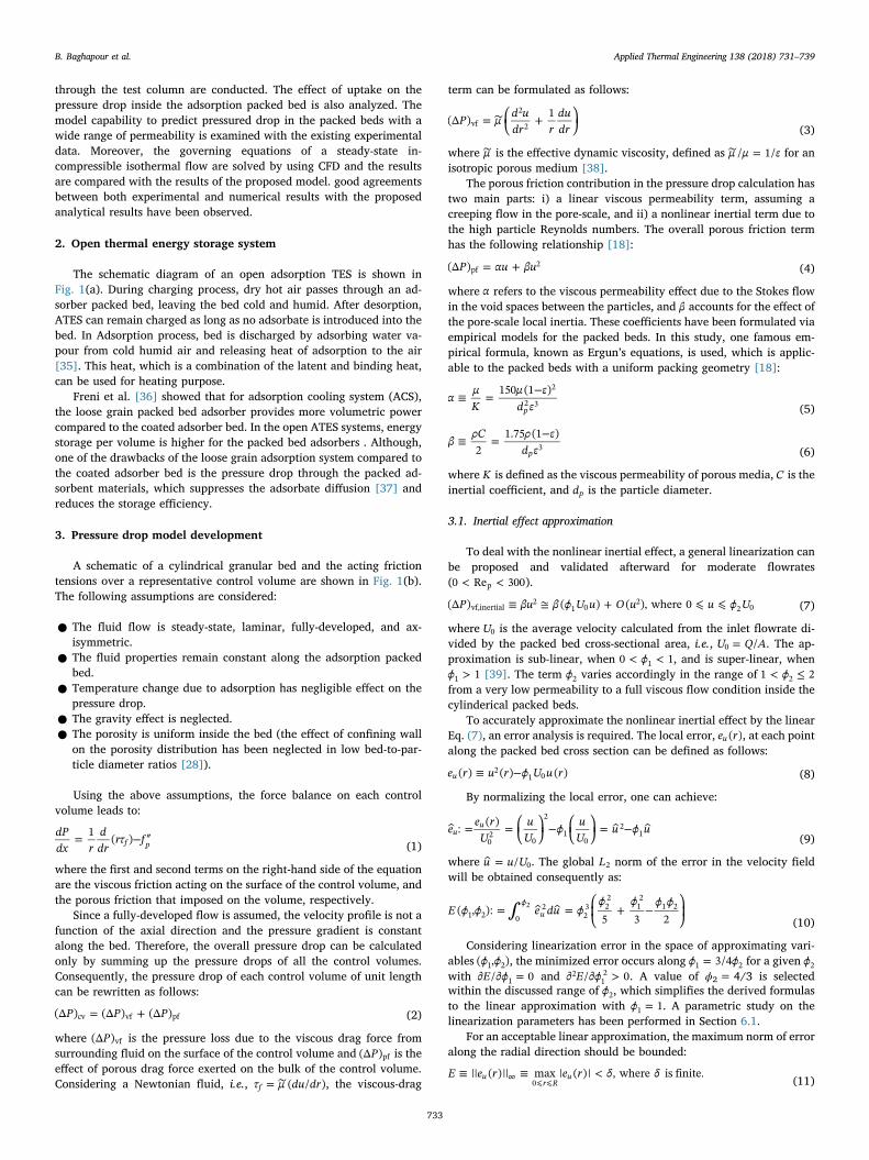
Fig. 3 compares the analytical, experimental, and CFD simulationdata for different inlet air velocity and desiccant column heights. Asshown, there is a good agreement between the present results and theexperimental data; at the maximum inlet air velocity, the relative dif-ference between the analytical results and the measured experimentaldata is 7.6% at air velocity of 0.73m/s for silica gel, and 15.3% at0.84m/s for zeolite beds. The averaged uncertainty of the measurementis estimated as 4.92% for the silica gel bed and 4.74% for the zeolitebed. The CFD model shows a 7.08% deviation from the experimentaldata at the maximum inlet velocity and perfectly matches with theanalytical results with 0.48% difference. This indicates consistencybetween the analytical results, the experimental data, and the numer-ical solution.
Fig. 4 compares the pressure gradient along the bed, dP dx/ , calcu-lated by the present model with the experimental data of randomly-
Fig. 2. Experimental testbed for pressure drop measurements in the cylindrical packed bed.
Table 1Testbed conditions for pressure drop measurements.
Adsorbent Porosity Particlediameter
Columnheight
Airflow velocity Initialcondition
Silica gel 0.375 3.2 mm 6–30 cm 0.13–0.83m/s dry (zerouptake)
Zeolite 4A 0.39 3.6 mm 6–30 cm 0.13–1.03m/s dry and wet
B. Baghapour et al. Applied Thermal Engineering 138 (2018) 731–739
735
packed bed of dry silica gels with a porosity of =ε 0.375 and dry zeolite4A with a porosity of =ε 0.39. Other packing arrangements, i.e. simplecubic (SC) and body centered cubic (BCC) [43] are also added forcomparison.
As shown in Fig. 4, pressure gradients of the tested desiccants liebetween SC and BCC arrangements. Accordingly, for a given particleReynolds number, the pressure gradient along the bed reduces at
Fig. 3. Comparison of the analytical model with the CFD simulation and ex-periments for the cylindrical packed column of silica gel with different heights.
Fig. 4. Pressure gradient along the packed bed for different packing arrange-ments compared to the proposed analytical model, Eq. (22).
Fig. 5. Comparison of dry and wet zeolite particles for pressure gradient alongthe packed bed.
Fig. 6. Comparison of dry and wet zeolite particles with analytical model forthe friction factor.
Table 2The effect of water uptake on pressure drop in wet with respect to dry zeolite 4Afor different column sizes.
Bedheight(cm)
Total pressuredifference,
= −P P PΔ d w (Pa)
Pressuredifference perbed height,
P HΔ / (Pa/cm)
Relativepressuredifference,
−P P P( )/d w d (%)
Relative frictionfactordifference,
−f f f( )/d w d (%)
6 57.5 9.58 12.50 13.0318 29.2 1.62 3.02 4.0530 54.2 1.81 0.82 0.29
Fig. 7. Comparison of the present analytical model with the present experi-ments, as well as the available experimental data in the literature [43,44,45],for different range of permeability.
Table 3Sorption characteristics of adsorbents for ideal energy storage density calcula-tion, considering the experimental conditions of = °T 23 C and =RH 55%. (themaximum water uptake is defined as the maximum mass of the adsorbed waterto the mass of the dry adsorbent).
Adsorbent Enthalpy of adsorption ( HΔ ads) Maximum uptake (wmax)
Silica gel 2.40MJ/kg [47] 0.40 kg/kgads [49]Zeolite 4A 3.05MJ/kg [47] 0.22 kg/kgads [50]
B. Baghapour et al. Applied Thermal Engineering 138 (2018) 731–739
736
packing arrangements with higher porosities. To investigate the effectof the uptake on the pressure drop, a series of experiments have beenperformed for fully wet zeolite packed bed and the results were com-pared to the results obtained from the experiment with dry zeolite.Fig. 5 compares the pressure gradient along the bed of dry and wetzeolite 4A with the analytical model. As shown in this figure, thepressure drop for the wet particles did not change significantly com-pared to the dry particles.
Fig. 6 compares the analytical results for the friction factor, definedin Eq. (30), for the analytical model with the experiment data of dryand wet zeolite 4A for the cylindrical packed bed.
⎜ ⎟= ⎛⎝
⎞⎠
ψ PρU
dH
Δ p12 0
2(30)
As shown in Fig. 6, the differences between dry and wet desiccantsbecome negligible as the column size increases. A maximum of about12% relative pressure difference was observed in the experiments forthe wet particles in 6 cm bed height versus the dry particles; while in30 cm bed height, the maximum relative difference was less than 1%.Table 2 shows the maximum differences in dry and wet conditions.According to this table, insignificant pressure differences per adsorberbed height can be observed at slightly larger beds ( >H 6.0 cm). Thiswas also found for relative pressure and friction factor differences.
As shown in Fig. 7, an intermediate condition can be observed be-tween one asymptote (very low permeability) and another asymptote(very high permeability) by increasing the porosity of packed bed from
high to low λ. According to this figure, the intersection of the twoasymptotes occurs at =λ 2 2 , where the maximum deviation fromboth asymptotes occurs.
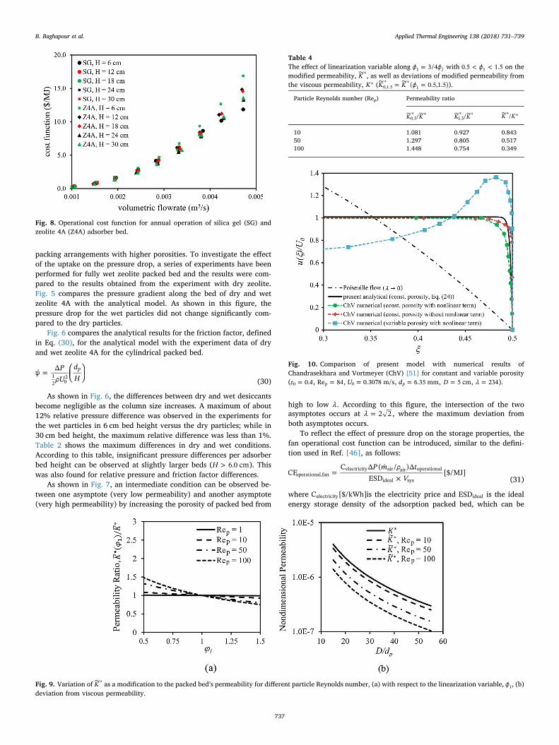
To reflect the effect of pressure drop on the storage properties, thefan operational cost function can be introduced, similar to the defini-tion used in Ref. [46], as follows:
=×
P m ρ tV
CFC Δ ( / )Δ
ESD[$/MJ]operational,fan
electricity air air operational
ideal sys (31)
where C [$/kWh]electricity is the electricity price and ESDideal is the idealenergy storage density of the adsorption packed bed, which can be
Fig. 8. Operational cost function for annual operation of silica gel (SG) andzeolite 4A (Z4A) adsorber bed.
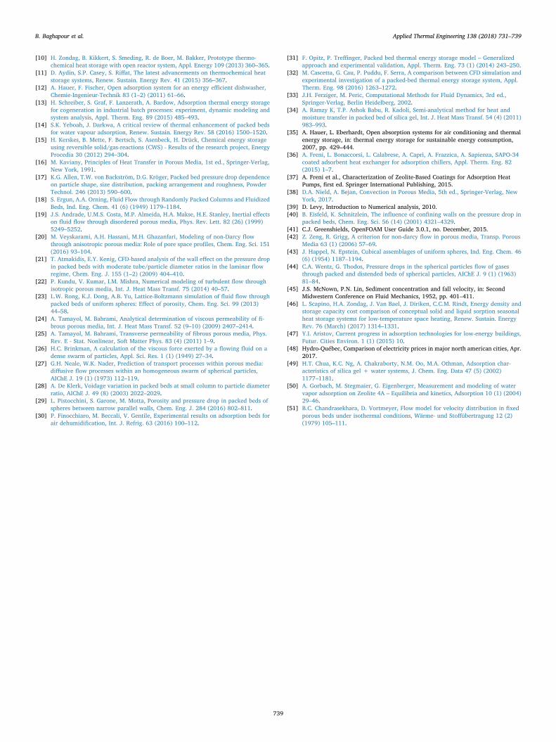
Fig. 9. Variation of ∼∗K as a modification to the packed bed’s permeability for different particle Reynolds number, (a) with respect to the linearization variable, ϕ1, (b)deviation from viscous permeability.
Table 4The effect of linearization variable along =ϕ ϕ3/41 2 with < <ϕ0.5 1.51 on themodified permeability, ∼∗K , as well as deviations of modified permeability fromthe viscous permeability, ∗K ( = =∼ ∼∗ ∗K K ϕ( 0.5,1.5)0,1.5 1 ).
Particle Reynolds number (Rep) Permeability ratio
∼ ∼∗ ∗K K/0.5∼ ∼∗ ∗K K/1.5
∼∗ ∗K K/
10 1.081 0.927 0.84350 1.297 0.805 0.517100 1.448 0.754 0.349
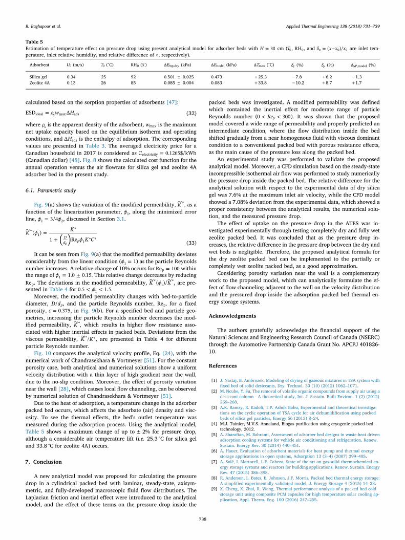
Fig. 10. Comparison of present model with numerical results ofChandrasekhara and Vortmeyer (ChV) [51] for constant and variable porosity( =ε 0.40 , =Re 84p , =U 0.3078 m/s0 , =d 6.35 mmp , =D 5 cm, =λ 234).
B. Baghapour et al. Applied Thermal Engineering 138 (2018) 731–739
737
calculated based on the sorption properties of adsorbents [47]:
= ρ w HESD Δsideal max ads (32)
where ρs is the apparent density of the adsorbent, wmax is the maximumnet uptake capacity based on the equilibrium isotherm and operatingconditions, and HΔ ads is the enthalpy of adsorption. The correspondingvalues are presented in Table 3. The averaged electricity price for aCanadian household in 2017 is considered as =C 0.1265$/kWhelectricity(Canadian dollar) [48]. Fig. 8 shows the calculated cost function for theannual operation versus the air flowrate for silica gel and zeolite 4Aadsorber bed in the present study.
6.1. Parametric study
Fig. 9(a) shows the variation of the modified permeability, ∼∗K , as afunction of the linearization parameter, ϕ1, along the minimized errorline, =ϕ ϕ3/41 2, discussed in Section 3.1.
=+
∼∗ ∗
∗ ∗( )K ϕ K
ϕ K C( )
1 ReDd p
1
1p (33)
It can be seen from Fig. 9(a) that the modified permeability deviatesconsiderably from the linear condition ( =ϕ 11 ) as the particle Reynoldsnumber increases. A relative change of 10% occurs for =Re 100p withinthe range of = ±ϕ 1.0 0.151 . This relative change decreases by reducingRep. The deviations in the modified permeability, ∼ ∼∗ ∗K ϕ K( )/1 , are pre-sented in Table 4 for < <ϕ0.5 1.51 .
Moreover, the modified permeability changes with bed-to-particlediameter, D d/ p, and the particle Reynolds number, Re ,p for a fixedporosity, =ε 0.375, in Fig. 9(b). For a specified bed and particle geo-metries, increasing the particle Reynolds number decreases the mod-ified permeability, ∼∗K , which results in higher flow resistance asso-ciated with higher inertial effects in packed beds. Deviations from theviscous permeability, ∼∗ ∗K K/ , are presented in Table 4 for differentparticle Reynolds number.
Fig. 10 compares the analytical velocity profile, Eq. (24), with thenumerical work of Chandrasekhara & Vortmeyer [51]. For the constantporosity case, both analytical and numerical solutions show a uniformvelocity distribution with a thin layer of high gradient near the wall,due to the no-slip condition. Moreover, the effect of porosity variationnear the wall [28], which causes local flow channeling, can be observedby numerical solution of Chandrasekhara & Vortmeyer [51].
Due to the heat of adsorption, a temperature change in the adsorberpacked bed occurs, which affects the adsorbate (air) density and visc-osity. To see the thermal effects, the bed’s outlet temperature wasmeasured during the adsorption process. Using the analytical model,Table 5 shows a maximum change of up to±2% for pressure drop,although a considerable air temperature lift (i.e. 25.3 °C for silica geland 33.8 °C for zeolite 4A) occurs.
7. Conclusion
A new analytical model was proposed for calculating the pressuredrop in a cylindrical packed bed with laminar, steady-state, axisym-metric, and fully-developed macroscopic fluid flow distributions. TheLaplacian friction and inertial effect were introduced to the analyticalmodel, and the effect of these terms on the pressure drop inside the
packed beds was investigated. A modified permeability was definedwhich contained the inertial effect for moderate range of particleReynolds number ( < <Re0 300p ). It was shown that the proposedmodel covered a wide range of permeability and properly predicted anintermediate condition, where the flow distribution inside the bedshifted gradually from a near homogenous fluid with viscous dominantcondition to a conventional packed bed with porous resistance effects,as the main cause of the pressure loss along the packed bed.
An experimental study was performed to validate the proposedanalytical model. Moreover, a CFD simulation based on the steady-stateincompressible isothermal air flow was performed to study numericallythe pressure drop inside the packed bed. The relative difference for theanalytical solution with respect to the experimental data of dry silicagel was 7.6% at the maximum inlet air velocity, while the CFD modelshowed a 7.08% deviation from the experimental data, which showed aproper consistency between the analytical results, the numerical solu-tion, and the measured pressure drop.
The effect of uptake on the pressure drop in the ATES was in-vestigated experimentally through testing completely dry and fully wetzeolite packed bed. It was concluded that as the pressure drop in-creases, the relative difference in the pressure drop between the dry andwet beds is negligible. Therefore, the proposed analytical formula forthe dry zeolite packed bed can be implemented to the partially orcompletely wet zeolite packed bed, as a good approximation.
Considering porosity variation near the wall is a complementarywork to the proposed model, which can analytically formulate the ef-fect of flow channeling adjacent to the wall on the velocity distributionand the pressured drop inside the adsorption packed bed thermal en-ergy storage systems.
Acknowledgments
The authors gratefully acknowledge the financial support of theNatural Sciences and Engineering Research Council of Canada (NSERC)through the Automotive Partnership Canada Grant No. APCPJ 401826-10.
References
[1] J. Nastaj, B. Ambrozek, Modeling of drying of gaseous mixtures in TSA system withfixed bed of solid desiccants, Dry. Technol. 30 (10) (2012) 1062–1071.
[2] M. Ncube, Y. Su, The removal of volatile organic compounds from supply air using adesiccant column - A theoretical study, Int. J. Sustain. Built Environ. 1 (2) (2012)259–268.
[3] A.K. Ramzy, R. Kadoli, T.P. Ashok Babu, Experimental and theoretical investiga-tions on the cyclic operation of TSA cycle for air dehumidification using packedbeds of silica gel particles, Energy 56 (2013) 8–24.
[4] M.J. Tuinier, M.V.S. Annaland, Biogas purification using cryogenic packed-bedtechnology, 2012.
[5] A. Sharafian, M. Bahrami, Assessment of adsorber bed designs in waste-heat drivenadsorption cooling systems for vehicle air conditioning and refrigeration, Renew.Sustain. Energy Rev. 30 (2014) 440–451.
[6] A. Hauer, Evaluation of adsorbent materials for heat pump and thermal energystorage applications in open systems, Adsorption 13 (3–4) (2007) 399–405.
[7] A. Solé, I. Martorell, L.F. Cabeza, State of the art on gas-solid thermochemical en-ergy storage systems and reactors for building applications, Renew. Sustain. EnergyRev. 47 (2015) 386–398.
[8] R. Anderson, L. Bates, E. Johnson, J.F. Morris, Packed bed thermal energy storage:A simplified experimentally validated model, J. Energy Storage 4 (2015) 14–23.
[9] X. Cheng, X. Zhai, R. Wang, Thermal performance analysis of a packed bed coldstorage unit using composite PCM capsules for high temperature solar cooling ap-plication, Appl. Therm. Eng. 100 (2016) 247–255.
Table 5Estimation of temperature effect on pressure drop using present analytical model for adsorber beds with =H 30 cm (T0, RH0, and = −δ x x x( )/x 0 0 are inlet tem-perature, inlet relative humidity, and relative difference of x , respectively).
Adsorbent U0 (m/s) T0 (°C) RH0 (%) PΔ exp,dry (kPa) PΔ model (kPa) TΔ max (°C) δρ (%) δμ (%) δ PΔ ,model (%)
Silica gel 0.34 25 92 0.501 ± 0.025 0.473 +25.3 −7.8 +6.2 −1.3Zeolite 4A 0.13 26 85 0.085 ± 0.004 0.083 +33.8 −10.2 +8.7 +1.7
B. Baghapour et al. Applied Thermal Engineering 138 (2018) 731–739
738
[10] H. Zondag, B. Kikkert, S. Smeding, R. de Boer, M. Bakker, Prototype thermo-chemical heat storage with open reactor system, Appl. Energy 109 (2013) 360–365.
[11] D. Aydin, S.P. Casey, S. Riffat, The latest advancements on thermochemical heatstorage systems, Renew. Sustain. Energy Rev. 41 (2015) 356–367.
[12] A. Hauer, F. Fischer, Open adsorption system for an energy efficient dishwasher,Chemie-Ingenieur-Technik 83 (1–2) (2011) 61–66.
[13] H. Schreiber, S. Graf, F. Lanzerath, A. Bardow, Adsorption thermal energy storagefor cogeneration in industrial batch processes: experiment, dynamic modeling andsystem analysis, Appl. Therm. Eng. 89 (2015) 485–493.
[14] S.K. Yeboah, J. Darkwa, A critical review of thermal enhancement of packed bedsfor water vapour adsorption, Renew. Sustain. Energy Rev. 58 (2016) 1500–1520.
[15] H. Kerskes, B. Mette, F. Bertsch, S. Asenbeck, H. Drück, Chemical energy storageusing reversible solid/gas-reactions (CWS) - Results of the research project, EnergyProcedia 30 (2012) 294–304.
[16] M. Kaviany, Principles of Heat Transfer in Porous Media, 1st ed., Springer-Verlag,New York, 1991.
[17] K.G. Allen, T.W. von Backström, D.G. Kröger, Packed bed pressure drop dependenceon particle shape, size distribution, packing arrangement and roughness, PowderTechnol. 246 (2013) 590–600.
[18] S. Ergun, A.A. Orning, Fluid Flow through Randomly Packed Columns and FluidizedBeds, Ind. Eng. Chem. 41 (6) (1949) 1179–1184.
[19] J.S. Andrade, U.M.S. Costa, M.P. Almeida, H.A. Makse, H.E. Stanley, Inertial effectson fluid flow through disordered porous media, Phys. Rev. Lett. 82 (26) (1999)5249–5252.
[20] M. Veyskarami, A.H. Hassani, M.H. Ghazanfari, Modeling of non-Darcy flowthrough anisotropic porous media: Role of pore space profiles, Chem. Eng. Sci. 151(2016) 93–104.
[21] T. Atmakidis, E.Y. Kenig, CFD-based analysis of the wall effect on the pressure dropin packed beds with moderate tube/particle diameter ratios in the laminar flowregime, Chem. Eng. J. 155 (1–2) (2009) 404–410.
[22] P. Kundu, V. Kumar, I.M. Mishra, Numerical modeling of turbulent flow throughisotropic porous media, Int. J. Heat Mass Transf. 75 (2014) 40–57.
[23] L.W. Rong, K.J. Dong, A.B. Yu, Lattice-Boltzmann simulation of fluid flow throughpacked beds of uniform spheres: Effect of porosity, Chem. Eng. Sci. 99 (2013)44–58.
[24] A. Tamayol, M. Bahrami, Analytical determination of viscous permeability of fi-brous porous media, Int. J. Heat Mass Transf. 52 (9–10) (2009) 2407–2414.
[25] A. Tamayol, M. Bahrami, Transverse permeability of fibrous porous media, Phys.Rev. E - Stat. Nonlinear, Soft Matter Phys. 83 (4) (2011) 1–9.
[26] H.C. Brinkman, A calculation of the viscous force exerted by a flowing fluid on adense swarm of particles, Appl. Sci. Res. 1 (1) (1949) 27–34.
[27] G.H. Neale, W.K. Nader, Prediction of transport processes within porous media:diffusive flow processes within an homogeneous swarm of spherical particles,AIChE J. 19 (1) (1973) 112–119.
[28] A. De Klerk, Voidage variation in packed beds at small column to particle diameterratio, AIChE J. 49 (8) (2003) 2022–2029.
[29] L. Pistocchini, S. Garone, M. Motta, Porosity and pressure drop in packed beds ofspheres between narrow parallel walls, Chem. Eng. J. 284 (2016) 802–811.
[30] P. Finocchiaro, M. Beccali, V. Gentile, Experimental results on adsorption beds forair dehumidification, Int. J. Refrig. 63 (2016) 100–112.
[31] F. Opitz, P. Treffinger, Packed bed thermal energy storage model – Generalizedapproach and experimental validation, Appl. Therm. Eng. 73 (1) (2014) 243–250.
[32] M. Cascetta, G. Cau, P. Puddu, F. Serra, A comparison between CFD simulation andexperimental investigation of a packed-bed thermal energy storage system, Appl.Therm. Eng. 98 (2016) 1263–1272.
[33] J.H. Ferziger, M. Peric, Computational Methods for Fluid Dynamics, 3rd ed.,Springer-Verlag, Berlin Heidelberg, 2002.
[34] A. Ramzy K, T.P. Ashok Babu, R. Kadoli, Semi-analytical method for heat andmoisture transfer in packed bed of silica gel, Int. J. Heat Mass Transf. 54 (4) (2011)983–993.
[35] A. Hauer, L. Eberhardt, Open absorption systems for air conditioning and thermalenergy storage, in: thermal energy storage for sustainable energy consumption,2007, pp. 429–444.
[36] A. Freni, L. Bonaccorsi, L. Calabrese, A. Caprì, A. Frazzica, A. Sapienza, SAPO-34coated adsorbent heat exchanger for adsorption chillers, Appl. Therm. Eng. 82(2015) 1–7.
[37] A. Freni et al., Characterization of Zeolite-Based Coatings for Adsorption HeatPumps, first ed. Springer International Publishing, 2015.
[38] D.A. Nield, A. Bejan, Convection in Porous Media, 5th ed., Springer-Verlag, NewYork, 2017.
[39] D. Levy, Introduction to Numerical analysis, 2010.[40] B. Eisfeld, K. Schnitzlein, The influence of confining walls on the pressure drop in
packed beds, Chem. Eng. Sci. 56 (14) (2001) 4321–4329.[41] C.J. Greenshields, OpenFOAM User Guide 3.0.1, no. December, 2015.[42] Z. Zeng, R. Grigg, A criterion for non-darcy flow in porous media, Transp. Porous
Media 63 (1) (2006) 57–69.[43] J. Happel, N. Epstein, Cubical assemblages of uniform spheres, Ind. Eng. Chem. 46
(6) (1954) 1187–1194.[44] C.A. Wentz, G. Thodos, Pressure drops in the spherical particles flow of gases
through packed and distended beds of spherical particles, AIChE J. 9 (1) (1963)81–84.
[45] J.S. McNown, P.N. Lin, Sediment concentration and fall velocity, in: SecondMidwestern Conference on Fluid Mechanics, 1952, pp. 401–411.
[46] L. Scapino, H.A. Zondag, J. Van Bael, J. Diriken, C.C.M. Rindt, Energy density andstorage capacity cost comparison of conceptual solid and liquid sorption seasonalheat storage systems for low-temperature space heating, Renew. Sustain. EnergyRev. 76 (March) (2017) 1314–1331.
[47] Y.I. Aristov, Current progress in adsorption technologies for low-energy buildings,Futur. Cities Environ. 1 (1) (2015) 10.
[48] Hydro-Québec, Comparison of electricity prices in major north american cities, Apr.2017.
[49] H.T. Chua, K.C. Ng, A. Chakraborty, N.M. Oo, M.A. Othman, Adsorption char-acteristics of silica gel + water systems, J. Chem. Eng. Data 47 (5) (2002)1177–1181.
[50] A. Gorbach, M. Stegmaier, G. Eigenberger, Measurement and modeling of watervapor adsorption on Zeolite 4A – Equilibria and kinetics, Adsorption 10 (1) (2004)29–46.
[51] B.C. Chandrasekhara, D. Vortmeyer, Flow model for velocity distribution in fixedporous beds under isothermal conditions, Wärme- und Stoffübertragung 12 (2)(1979) 105–111.
B. Baghapour et al. Applied Thermal Engineering 138 (2018) 731–739
739