applied surface science - ایران مواد-مرجع...
TRANSCRIPT

P
BCa
b
a
ARRAA
KPSSHES
1
tst
pawwoiwBttl
g
h0
Applied Surface Science 349 (2015) 403–414
Contents lists available at ScienceDirect
Applied Surface Science
jou rn al h om ep age: www.elsev ier .com/ locate /apsusc
lasma nitriding of HP13Cr supermartensitic stainless steel
runa C.E.S. Kureloa, Gelson B. de Souzaa,∗, Silvio L. Rutz da Silvaa, Francisco C. Serbenaa,arlos E. Foerstera, Clodomiro Alves Jr. b
Department of Physics, Universidade Estadual de Ponta Grossa, Av. Gen. Carlos Cavalcanti n◦ 4748, 84.030-000 Ponta Grossa, PR, BrazilDepartment of Mechanical Engineering, Universidade Federal do Rio Grande do Norte, Campus Universitário s/n, 59072-970 Natal, RN, Brazil
r t i c l e i n f o
rticle history:eceived 9 January 2015eceived in revised form 10 April 2015ccepted 30 April 2015vailable online 6 May 2015
eywords:lasma nitridingupermartensitic stainless steelurfaceardness
a b s t r a c t
Supermartensitic stainless steels (SMSS) are commonly employed in the oil exploitation industry andpresent a good balance between the necessary physical and chemical properties and financial costs.Certain applications, such as in extreme corrosive and abrasive environments, demand improvementsin the surface properties of these steels. In the present work, HP13Cr SMSS with a fully martensiticmicrostructure were plasma nitrided in the 350–450 ◦C range. The high diffusivity and low solubility ofnitrogen in the martensitic structure allowed the production of thick layers (16–61 �m) containing �-Fe2–3N, �′-Fe4N and expanded phase (�N) in all the temperatures. In addition, anisotropic sputtering rateand N-diffusion were observed for different grain orientations. Mechanical properties were measuredby instrumented indentation, appropriately corrected from roughness effects on the results. Hardnessprofiles increased from 3.8 GPa (bulk) to ∼14 GPa (near surface region) in all the working temperatures,
lastic moduluscratch test
whereas the elastic modulus was 230 GPa, presenting no statistically significant differences with respectto the bulk value. Nanoscratch tests revealed a hardened-ductile like behavior of these nitride layers.The surface tribo-mechanical behavior was correlated with elastic–plastic responses of the precipitate-containing texturized layers. Results are interpreted in light of the effectiveness of plasma nitriding tomodify the surface properties of SMSS.
. Introduction
Supermartensitic stainless steels (SMSS) are currently used byhe petrochemistry industry in gas and oil pipelines for the deepea environment, subjected to high temperatures and pressures inhe presence of corrosive agents such CO2, H2S and Cl− [1–4].
SMSS belong to the Fe–Cr–Ni–Mo system with relatively lowercentage of alloying elements. As an economic alternative toustenitic and duplex steels, SMSS oil pipes present reducedall thickness and weight, with improved mechanical properties,eldability and corrosion resistance. These features are obtained
n SMSS by controlling the alloying elements and the austen-te/martensite volume ratio. Particularly, the enhanced SMSS
eldability is due to the low carbon content of 0.02 wt% or less.esides, the lower carbon content and the addition of Mo (∼2 wt%),
ogether with the 13% Cr, helps to promote corrosion protection inhe aggressive crude oil and seawater environment [1,3,5–7]. Theow C concentration requires increased Ni content up to around 6%,∗ Corresponding author. Tel.: +55 42 3220 3044; fax: +55 42 3220 3042.E-mail addresses: [email protected], [email protected],
[email protected] (G.B. de Souza).
ttp://dx.doi.org/10.1016/j.apsusc.2015.04.202169-4332/© 2015 Elsevier B.V. All rights reserved.
© 2015 Elsevier B.V. All rights reserved.
which stabilizes austenite in higher temperatures [1,3]. The Cr/Niratio promotes the formation of martensitic microstructure withretained austenite, which can be controlled by appropriate heat andtempering treatments. Zou and co-workers [4], investigating thetempering process effects on 13Cr–4Ni–1Mo SMSS, reported thatthe microstructure with 11.5% retained austenite promoted thebest results for tensile and yield strength, elongation and hardness.
Much effort has been made to improve the SMSS bulk proper-ties. The material’s thermal history is a determinant parameter forits mechanical performance, since unwanted �- and �-ferrite pre-cipitates can cause strength reduction. Such concern is critical inwelding, that locally alters the microstructure in the heat affectedzones [8,9], besides favoring hydrogen induced cracking [2,7,10].Precipitation of intermetallic compounds such as Fe2Mo can alsodeteriorate the SMSS mechanical strength. Otherwise, a modifiedcomposition with 0.13% Ti was reported to present, after temper-ing, fine Ti(C,N) particles dispersed in a martensitic matrix, withsuperior mechanical properties than the Ti-free SMSS [6].
The surface properties of SMSS used in gas and oil pipelines also
demand attention when employed in aggressive environments.In recent years, oil deposits have been discovered and aimed toexploitation in rock layers lying thousands of meters beneath deepseas. The Pre-salt layer, an oil field in the Brazil offshore coast, is
4 urface
b7[moplcc
bsihow
owp[anti[icobtowt(
lprocd
HcmBtmi
2
2
tsM
Ssttf
04 B.C.E.S. Kurelo et al. / Applied S
elieved to accumulate 109 barrels of oil and gas, situated around000 m depth (the ocean floor is 2000–3000 m from the surface)11]. High pressures and temperatures and abundant corrosive ele-
ents must be challenged to reach reservoirs situated in the midstf a thick and deep salt layer. Besides, intense abrasion occurs in theipe’s interior walls by sand particles mixed with oil. In the Pre-salt
ayer, special steels are also demanded as raw materials for valves,onnection points and peripheral devices of “subsea trees”, whichontrol the oil pump from the wellbore to the platform above.
The formation of nitride precipitates and/or expanded phasesy plasma-based ion implantation processes can altogether affordignificant improvements on the surface mechanical and tribolog-cal features of stainless steels [12–15]. Hardness can be raised asigh as five times, whereas friction and wear rate decreases aroundne order of magnitude [16,17]. These results were observed for aide variety of steels such as ferritic, austenitic, and duplex ones.
In the case of martensitic stainless steels, previous works corrob-rate the surface protective effects of plasma-based treatments asell. A known effect of PN is the production of a nitrogen expandedhase (termed S-phase) in austenitic steels [18]; similarly, Kim et al.19] found that expanded martensite, in analogy to the expandedustenite, was produced on AISI 420 steel submitted to RF plasmaitriding at 400 ◦C, resulting in a surface hardness increase of 4.3imes. A carbon expanded martensite, in addition to Fe3C precip-tates, was reported for AISI 420 submitted to plasma carburizing20]. This same martensitic steel, submitted to PN at temperaturesn the range 480–560 ◦C, presented a compound layer structureontaining fine and homogeneous precipitates of Fe4N, Fe2–3N, CrNver a diffusion zone [21]. Results obtained with other plasma-ased treatments [22–24] are also suggestive of improving theribological performance of martensitic stainless steels. Specificallyn SMSS, Fernandes et al. [25] observed that wear rates decreasedith heat treatments in the range 400–500 ◦C in samples submitted
o PN, and in samples treated by plasma nitriding and carburizingPNC).
The nitriding effects to the anti-corrosion properties of stain-ess steels are taken into consideration as well [26,27]. The heatingarameters involved in nitriding can compromise the corrosionesistance of these alloys, as observed by [28,29]. Thus, the controlf the plasma treatment conditions can lead to phases that promoteorrosion resistance, as well as to prevent sensitization (chromiumepletion) [18].
The present work focuses on the DC plasma nitriding of the SMSSP13-Cr. The mechanical properties and scratch resistance wereharacterized at nanoscale and correlated with morphological andicrostructure modifications running at the near surface region.
ecause several martensite to austenite ratios can be achieved inhe bulk SMSS and hence influence in different manners the surface
echanical response, here, the nitriding processes were performedn samples with fully martensitic microstructure.
. Experimental procedure
.1. Sample preparation
Samples with 15 mm × 15 mm × 2 mm (height × width ×hickness) were cut from a block of supermartensitic stainlessteel HP13Cr, with composition (wt%) 13%Cr, 5% Ni, 0.45% Mn, 2%o, 0.025% C.Since several martensite/austenite mixtures are allowed in
MSS, and because the substrate beneath modified surfaces
trongly affects their mechanical and tribological responses [30],he samples microstructures were initially homogenized prioro nitriding. This procedure intends to rule out spurious effectsrom the many possible bulk conditions, focusing on the surfaceScience 349 (2015) 403–414
tribo-mechanical response for a pristine SMSS. The fully marten-sitic microstructure was achieved by a two-step heat treatment[1,31,32]. The first one was the austenitizing into a preheated fur-nace, with subsequent quenching. The optimal conditions for theseprocesses were investigated by heating samples up to 975, 1000,1025 and 1100 ◦C for 30 min, in air, with subsequent quenchingin a bath of distilled water and ice at 0 ◦C. An additional batch wasprepared where samples were heated at the same previous temper-atures and then quenched in mineral oil at 20 ◦C. Both water andoil were contained in 1 L beakers. These methods changed the steelmicrostructure to austenite (above 950 ◦C) with subsequent rapidtransformation to martensite [9,33]. The second step was the tem-pering, carried out concomitantly with the nitriding process in theplasma chamber, which temperatures correspond to the temperingrange for steels [31,32]. It is worth mention that such process doesnot affect the diffusion kinetics during nitriding, since metastableatoms in the lattice shifts to the equilibrium [34]. In this report,samples nominated as “Reference” correspond to the not nitridedones, picked from the austenitized and quenched samples treatedin the best conditions found in step 1, as discussed in Section 3.1,and tempered inside a furnace under Argon atmosphere at 400 ◦Cfor 6 h.
After austenitizing and tempering, samples were polished tomirror finishing by grinding using successive SiC papers up toP1200, and final polishing up to 1 �m diamond paste, followed bya final polishing in colloidal silica solution with 85 vol.% of H2O2.Cleaning was performed twice in ultrasound bath using acetonefor 15 min.
2.2. Plasma nitriding
The SMSS samples were nitrided in a custom-made DC glowdischarge (GD) system, consisting of a chamber, vacuum system,power supply, and pressure and temperature controllers. Aiming toremove contaminants and oxides from the surface, pre-sputteringtreatment was performed in H2 atmosphere at 150 ± 10 ◦C for 1 h,at 300 Pa pressure. The nitriding atmosphere was a mixture of 20%N2 80% H2 (vol.), with gas inlet 4 sccm and 16 sccm, respectivelyand total pressure kept 300 Pa. The working temperatures weremeasured using a backside thermocouple and controlled using theplasma current (in the range 200–300 mA). At these conditions, thevoltage ranged from 370 to 407 V according to the nitriding tem-perature. The average ion energy in glow discharge systems can beestimated by means of the L/� ratio, where L is the sheath width and� the mean free path [35]. In the present situation, L is about 1.5 mm,� can be estimated as ∼0.5 mm, and therefore L/� ∼ 3. As a result,the average ion energy for the employed voltages is about 250 eV.Three samples batches were prepared, using the same treatmenttime (6 h) and different temperatures:
(i) 350 ◦C(ii) 400 ◦C
(iii) 450 ◦C
Temperature fluctuations were at most ±10 ◦C in all thesituations.
2.3. Crystalline structure and morphology
Structural changes were characterized by X-ray diffraction –XRD (Rigaku Ultima IV) with CuK� radiation (� = 0.15406 nm) underthe Bragg–Brentano (�–2�) geometry. The diffractograms were
obtained in the range 30–90◦ with 0.02◦ steps and a counting timeof 4 s at each step. The diffraction peaks were identified accord-ing to powder crystallographic data, with the following PDF cardnumbers: 33-397 (�-austenite); 34-396 (�′-martensite); 86-231

urface
(3(m
mm
acoSysar
2
uOtp4w
rtiflazch
tw1o([atpc
H
wv
t2
2
iws5i(fic
from the alloy. If chromium is segregated to form these compounds,they will form Cr2O3 at the surface, depleting the bulk and affect-ing the corrosion resistance of the material [38]. Such carbides areformed due to the carbon availability in the material [9], despite
Fig. 1. X-ray diffractograms of SMSS samples submitted to austenitizing and heat-treatments, carried out previously to the plasma nitriding process. The as-received
B.C.E.S. Kurelo et al. / Applied S
�′-Fe4N); 49-1664 and 72-2126 (�-Fe2–3N); 76-2494 (CrN);5-783 (Cr23C6); 80-1701 (Mn23C6); 36-1482 (Cr7C3); 75-1499Fe7C3); 80-1699 (Mn7C3); 76-1877 (Fe3C). The �N (expanded
artensite) was identified according to Kim et al. [19].Topography and roughness were analyzed by atomic force
icroscopy – AFM (Shimadzu SPM 9600) operating in contactode.The indentation imprints and scratch grooves were imaged by
field emission scanning electron microscopy – FEG-SEM (Tes-an Mira 3) and SEM (Jeol JSM-6360 LV). Elemental analyses werebtained by energy-dispersive spectroscopy – EDS (Oxford XMaxNDD) operating at 20 kV. The electron beam spot size in EDS anal-ses was 69 nm. To visualize the produced layers, cross-sectionedamples were etched with Vilela’s and Murakami’s reagents andnalyzed by FEG-SEM and optical microscopy (Olympus bx51),espectively.
.4. Mechanical properties
Hardness and elastic modulus profiles were obtained bysing a NanoIndenter XP (MTS), following the well-establishedliver–Pharr method [36]. A pyramidal Berkovich-type diamond
ip was employed, calibrated with fused-silica sample with knownroperties (H = 9.5 GPa and E = 73.0 GPa). Loads varied from 0.8 to00 mN in 10 successive loading-unloading cycles. Each sampleas indented at 40 different sites, 100 �m apart one from another.
The intense sputtering taking place in plasma-based processesesults in peaks and valleys on the surfaces with varied height dis-ribution. The indenter tip and asperity interactions cause errorsn the Oliver–Pharr analytical method, which was developed forat surfaces. In order to minimize such problem, a contact stiffnessnalysis was applied on the indentation data, which corrects theero tip contact depth in the loading-unloading curves [37]. Theonventional method [36] was subsequently reapplied to calculateardness and elastic modulus of the nitrided surfaces.
In order to investigate hardening effects in deeper regions onhe modified surfaces, additional microhardness tests (Hoatec Inc.)ere carried out using a Vickers indenter and loads in the range
000–20,000 mN. Hardness in the Oliver and Pharr method isbtained from the ratio between load (Pmax) and the projected areaAprojected) of a Berkovich tip (the triangular base) during contact36], whereas Vickers hardness is determined after the load reliefnd using the contact area of the square based pyramid faces withhe material [34]. Aiming to minimize differences in the calculatedrofiles, here an approaching to the Oliver and Pharr definition wasonsidered for microhardness tests, Hvickers:
vickers = Pmax
Aprojected= Pmax
d2/2(1)
here d is the averaged diagonal of the imprint-projected area, asisualized by a microscope.
As additional investigations, single loading instrumented inden-ations were carried out directly on the sample’s cross sections with00 mN applied load.
.5. Nanoscratch tests
Scratch tests were performed with the same instrumentedndentation facility, following the Berkovich-tip edge direction
ith scratch velocity of 10 �m/s and 600 �m length. The initialurface morphology was obtained by scanning the track under a0 �N constant load; then, the tip displacement profile was mon-
tored during scratching up to 400 mN with constant loading rate6.7 mN/s). After that, the groove morphology was once again veri-ed (the residual depth) under 50 �N load. The penetration profilesorrespond to the displacement curves subtracted from the original
Science 349 (2015) 403–414 405
profile. For each loading condition, the surfaces were tested at threedifferent locations.
3. Results and discussion
3.1. Crystalline structure
Before plasma nitriding, the SMSS samples were submitted toaustenitizing and quenching treatments.
Fig. 1 shows XRD diffractograms of the pristine and the heatedSMSS samples at different temperatures and quenched in (a) waterand (b) oil. The as-received material presented diffraction peaksascribed to martensite (�′) and austenite (�) phases. In Fig. 1a (oilquenching), after heating at 975 ◦C and 1025 ◦C, the � phase van-ished, whereas peaks with small intensities indicated that carbideswere precipitated in the matrix. According to the phase diagramof this alloy [33], the carbide phases comprise the M23C6, M7C3,and M3C stoichiometries, where M corresponds to a metal atom
(untreated) material presented contributions of martensite and austenite. The fullymartensitic microstructure was attained at the indicated temperatures, with sub-sequent quenching in (a) mineral oil and (b) distilled water. The carbide phases (*)comprise M23C6, M7C3, and M3C stoichiometries, where M correspond to a metalatom. �′ = martensite; � = austenite.

4 urface Science 349 (2015) 403–414
ttopccTttd[c
pHth
fsptttqcstmpc
adtTapFpDwptpr
bamliriaesoni
[wpis
Fig. 2. X-ray diffractograms of SMSS samples plasma nitrided (PN) at the indicatedtemperatures. The reference sample (austenitized, quenched and tempered in Ar,
06 B.C.E.S. Kurelo et al. / Applied S
he small C-amount in the alloy (∼0.01 wt%). It is worth mentioninghat samples were grounded after austenitizing and quenching inrder to remove the reaction layer produced by the heating/coolingrocesses. Moreover, carbon mobility is faster in martensite asompared to austenite, as latter resumed in Section 3.2. Otherwise,arbides were not identified in the sample austenitized at 1100 ◦C.here are important factors affecting the alloy at this temperaturehat can prevent carbide precipitation in large amounts. At 1100 ◦C,he crystalline structure was fully austenitic [33] and the chromiumiffusivity was enhanced [39]. Moreover, according to Durham et al.38], the carbide dissolution takes place at such thermodynamiconditions.
The treatments with subsequent quenching in water (Fig. 1b)resented the same features as observed for the oil quenching.owever, carbides were precipitated regardless the austenitizing
emperature because of the reduced cooling efficiency, since wateras a lower heat capacity than the mineral oil.
The above results indicated that the heat treatment at 1100 ◦Collowed by oil quenching was effective in obtaining a fully marten-itic microstructure, with less significant (not detectable) carbiderecipitation. Thus, initially the SMSS samples were submittedo this protocol, whereas the tempering was achieved concomi-antly with the plasma nitriding process. For comparison purposes,he SMSS reference sample (untreated) was austenitized anduenched, and subsequently tempered in Argon atmosphere inonditions similar to the nitriding ones. In the analysis presentedubsequently, several effects will be correlated with the pris-ine martensitic microstructure of the material. It is important to
ention that in �′ + � containing SMSS, tailored for applicationurposes, martensite is the predominant microstructure with aoncentration above 85% [4].
Fig. 2 shows X-ray diffractograms of the reference samplend the SMSS plasma nitrided at the indicated temperatures. Theiffractograms of nitrided SMSS disclosed more substantial changeshan the observed in similar treatments of austenitic steels [16,40].he broad peaks at ∼43◦ and ∼64◦ in the lower temperatures, 350 ◦Cnd 400 ◦C, can be atributted to the nitrogen-expanded martensitehase (�N), which comprises several Fe(N) sub-estoichiometries.e(N) is a metastable, precipitate-free and supersaturated phaseroduced by the interstitial Nitrogen into the �′ matrix [18].ifferently from austenitic steels, �′-Fe4N and �-Fe2+xN phasesere formed in SMSS even at the lowest temperature, 350 ◦C. Theresence of nitride phases in the diffractograms increased withemperature as the �N decreased. The �-Fe2+xN (0 ≤ x ≤ 1) com-ound comprises several stoichiometries from Fe2N to Fe3N, alsoesulting in broad peaks.
The above results are justified based on the intrinsic differencesetween the body-centered tetragonal martensite (�′) and the fcc-ustenite (�) structures. Concerning the nitrogen solubility, the �icrostructure (fcc) differs from the ferrite (bcc) because it presents
arger octahedral interstices to accommodate the N-atoms [41]. Fornstance, the reported concentrations at 590 ◦C are 2.4 and 0.1 wt%,espectively [32,41]. Because interstices are available in �′ at sim-lar positions as found in the ferrite [32], the N-solubility in �′ islso expected to be lower than in the � unit cell. The low solubilitynables N-rich phases (Fe2N, Fe3N) to precipitate in the marten-itic microstructure even in the presence of lower concentrationf nitrogen in solid solution [18]. Also important is the enhanceditrogen diffusivity in the martensitic steels as compared to austen-
te, discussed in Section 3.2.Because of the chromium depletion above 420 ◦C
16,18,24,40,42,43], CrN was also indexed in Fig. 2 for 450 ◦C,
hich is denoted specially by the peak at ∼63◦. Chromiumresents high affinity with nitrogen and presents enhanced mobil-ty from substitutional sites at such thermodynamic conditions,egregating CrN preferentially at grain boundaries [15,18,32]. As
but not nitrided) presented only martensite (�′) peaks. After PN, the nitride com-pounds �′(Fe4N), �(Fe2+xN) and CrN, as well as the N-expanded martensite phase(�N), were formed with respect to the processing conditions.
observed in the work by Fernandes et al. [25] on plasma nitridingand nitrocarburizing on SMSS, chromium nitride content increaseswith the treatment temperature, whereas the iron nitrides contentconversely diminishes.
3.2. Morphology
The progressive microstructure changes, as observed afternitriding, were followed by drastic alterations in the surfaces mor-phologies. Fig. 3 presents cross-section images of the SMSS nitridedat the three working temperatures. Different etching reagentsallowed visualizing the modified regions by electron (Fig. 3a) andoptical (Fig. 3c) microscopies, with good agreement in the thick-ness measurements. In Fig. 3a, the near surface regions modifiedby PN revealed evident changes in morphology, as compared withthe substrate (where grain boundaries were evidenced). In Fig. 3b,the nitrogen/iron concentration (in at.%) is presented as a func-tion of depth for the sample nitrided at 400 ◦C, quantified by EDSpoint analysis through the line shown in Fig. 3a – 400 ◦C case. TheN/Fe concentration ratio was constant at ≈0.25 (corresponding to∼25% N) up to approximately 25 �m below the surface. This regionis ascribed to the nitride layer, containing �-Fe2–3N and �′-Fe4N
phases indexed in the XRD results (Fig. 2). From 25 to 39 �m,still inside the modified layer, the concentration ratio decreasedcontinuously up to zero. Such region can be related to the nitrogendiffusion zone (the expanded phase �N).
B.C.E.S. Kurelo et al. / Applied Surface Science 349 (2015) 403–414 407
Fig. 3. (a) Cross section FEG-SEM images for the plasma nitrided SMSS samples at the indicated temperatures, etched with Vilela’s reagent. Regions indicated by NL and�NL correspond to nitride (compound) and diffusion layers, respectively. The insets show details of the modified layer at the 350 ◦C sample, and grain boundaries revealedin the bulk region of the 450 ◦C sample. (b) The nitrogen/iron concentration, in at.%, obtained by EDS point analysis carried out in several points through the line indicatedi tching with Murakami’s reagent, where NL and �NL regions can be distinguished. Layerst /Fe profile.
euw(ttliw
1tcrmap
Table 1Average roughness (Ra), layer thickness and hardness of the SMSS HP13Cr plasmanitrided at the indicated temperatures.
Sample Ra (nm) Layer thickness (�m) Hardness (GPa)b
Referencea 15 ± 01 – 4.0 ± 0.1PN – 350 ◦C 86 ± 03 16.0 ± 1.7 14.2 ± 0.9PN – 400 ◦C 365 ± 23 35.3 ± 3.6 13.5 ± 1.4PN – 450 ◦C 437 ± 21 61.2 ± 2.7 11.7 ± 2.4c
a The SMSS after heat treatment at 1100 ◦C and oil quenching, with subsequentannealing in Argon.
b Average hardness values calculated from hardness profiles of Fig. 7, obtained
n (a) for the 400 ◦C sample. (c) Micrographs obtained by optical microscopy after ehicknesses for the 400 ◦C sample are in agreement with regions identified in the N
Notably, optical microscopy micrographs shown in Fig. 3cnabled to distinguish two different regions in each sample: anpper layer, followed by an intermediate brighter zone contrastingith the substrate beneath. In the 400 ◦C sample, the layers width
∼23 and ∼12 �m) agree very well with the different zones iden-ified in the N/Fe profile, Fig. 3c. These regions were ascribed tohe nitride (compound) layer and the diffusion layer, respectivelyabeled as NL and �NL in all panels of Fig. 3. The higher the nitrid-ng temperature was, the thicker the NL and thinner the �NL were,
hich is also in accordance with the XRD results (Fig. 2).The layer thickness (NL + �NL) increased with temperature from
6 to 61 �m, as summarized in Table 1. Such thicknesses are largerhan the observed in austenitic steels plasma nitrided at the sameonditions (from 1 to 10 �m) [16,40,44]. Otherwise, the modified
egions were comparable with that produced in other steels withartensitic microstructures as the AISI 420 (from 12 to 50 �m),lso treated in similar conditions [19,24,43]. The enhanced nitrogenenetration and the nitriding effects on SMSS are understood based
from instrumented indentation, over the range 300–1100 nm.c See text of Section 3.3.
on the particular geometric features of the martensite microstruc-
ture, as follows. The nitrogen diffusion in the steel matrix isessentially interstitial, meaning that it is several orders higher thanthe substitutional-vacancy solute diffusion. By assuming that the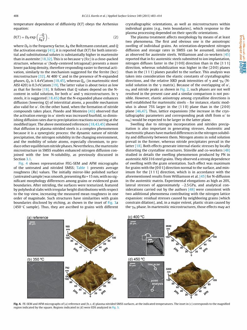
4 urface
te
D
wtttslvmpAacsdactimtbpadmjS
or(nbbtob(
Fr
08 B.C.E.S. Kurelo et al. / Applied S
emperature dependence of diffusivity D(T) obeys the Arrheniusquation:
(T) = D0 exp( −Q
kBT
), (2)
here D0 is the frequency factor, kB the Boltzmann constant, and Qhe activation energy [41], it is reported that D(T) for both intersti-ial and substitutional solutes is substantially higher in martensitehan in austenite [18,32]. This is so because � (fcc) is a close-packedtructure, whereas �′ (body-centered tetragonal) presents a moreower packing density, therefore responding easier to thermal acti-ation, similarly to the mechanism suggested for the ferrite (bcc)icrostructure [32]. At 400 ◦C and in the presence of N-expanded
hases, Q� is 1.4 eV/atom [18,45], whereas Q�′ (in martensitic steelISI 420) is 0.3 eV/atom [19]. The latter value is about twice as lows that for ferrite [18]. It follows that Q values depend on the N-ontent in solid solution, for both �′ and � microstructures. In �teels, it is suggested [18,45] that the N-expanded phase enhancesiffusion (lowering Q) of interstitial atoms, a possible mechanismlso valid for �′. On the other hand, when the formation of nitrideompounds takes place, Pinedo and Monteiro [43] observed thathe activation energy in �′ steels was increased fourfold, so dimin-shing diffusion rates due to precipitation reactions occurring at the
odified layer. The above mentioned references [18,43,45] showedhat diffusion in plasma nitrided steels is a complex phenomenonecause it is a synergistic process: the dynamic nature of nitriderecipitation, the nitrogen solubility in the changing environment,nd the mobility of solute atoms, especially chromium, to pro-uce other equilibrium nitride phases. Nevertheless, the martensiteicrostructure in SMSS enables enhanced nitrogen diffusion con-
oined with the low N-solubility, as previously discussed inection 3.1.
Fig. 4 shows representative FEG-SEM and AFM micrographsf the untreated and nitrided SMSS; Table 1 presents averageoughness (Ra) values. The initially mirror-like polished surfaceuntreated sample) was smooth, presenting Ra = 15 nm, with no sig-ificant morphology differences among grains or evidenced grainoundaries. After nitriding, the surfaces were texturized, featuredy polyhedral slabs with irregular height distributions with respect
o the top view, increasing the measured mean roughness in onerder of magnitude. Such structures have similarities with grainoundaries disclosed by etching, as shown in the inset of Fig. 3a450 ◦C sample). Thus, they are ascribed to grains with differentig. 4. FE-SEM and AFM micrographs of (a) reference and (b, c, d) plasma nitrided SMSS suegion indicated by the square. Regions indicated in (d) were EDS analyzed in Fig. 5.
Science 349 (2015) 403–414
crystallographic orientations, as well as microstructures withinindividual grains (e.g., twin boundaries), which response to theplasma processing depended on their specific orientations.
The plasma treatment affects morphology by means of at leasttwo phenomena. The first and obvious one is the anisotropicswelling of individual grains. An orientation-dependent nitrogendiffusion and storage rates in SMSS can be assumed, similarlyas observed for austenite steels. Williamson and co-workers [45]reported that in fcc austenitic steels submitted to ion implantation,nitrogen diffuses faster in the [1 0 0] direction than in the [1 1 1]direction, whereas solubilization was higher in the (2 0 0) planesthan in the (1 1 1) planes parallel to the surface. This analysis wastaken into consideration the elastic constants of crystallographicdirections, and the relative XRD peak intensities of � and �N (N-solid solution in the � matrix). Because of the overlapping of �′,�N and nitride peaks as shown in Fig. 2, such phases are not wellresolved in the present case and a similar comparison is not pos-sible. However, elastic anisotropy among crystalline directions iswell established for martensitic steels – for instance, elastic mod-ulus is about 75% larger in the (1 1 0) plane than in the (2 0 0)plane [46,47]. Thus, lattice expansions (the increase in the crys-tallographic parameters and corresponding peak shift from �′ to�N) would be expected to be larger in the latter plane.
Swelling due to nitrogen incorporation and nitrides precip-itation is also important in generating stresses. Austenitic andmartensitic phases have marked differences in the nitrogen solubil-ity and diffusivity between them. Nitrogen atoms in solid solutionprevail in the former, whereas nitride precipitates prevail in thelatter [18]. Both effects generate internal elastic stresses by locallydistorting the crystalline structures. Stinville and co-workers [48]studied in details the swelling phenomenon produced by PN inaustenitic AISI 316 steel grains. They observed a strong dependenceof swelling with the grain orientation. Such effect was maximumfor grains with the [0 0 1] direction normal to the surface, and min-imum for the [1 1 1] direction, which is in accordance with theaforementioned results from Williamson et al. [45] for N-diffusionin the austenitic matrix. Experimental elongations as high as 20%,lateral stresses of approximately −2.5 GPa, and analytical con-siderations carried out by the authors [48] were consistent with
two additional phenomena contributing with the nitrogen latticeexpansion: residual stresses caused by neighboring grains (whichconstrain dilation), and, in a major extent, plastic strain caused bythe �N phase. In martensitic microstructures, those effects may act
rfaces, at the indicated temperatures. The inset in (c) corresponds to the magnified

urface Science 349 (2015) 403–414 409
iloo
ofodastittisiwF
sasa[tsodiata
esmtwwtacwranawa(tbe
bbnpc[Ster
Fig. 5. FEG-SEM image and EDS analysis of the sample plasma nitrided at 450 ◦C,corresponding to regions indicated in Fig. 4d: (a) point analysis and (b) line scan.Abrupt differences in topography are ascribed to grain swelling (see text for details).
compounds �, �′ and CrN, predominating over �N.
B.C.E.S. Kurelo et al. / Applied S
n different proportions, given the relatively high N-diffusivity andow solubility rates, what demands further investigations. Analysisf Fig. 4 suggests that swelling in SMSS is in the range of hundredsf nanometers, similarly as measured by [48] in AISI 316.
A second possible explanation to the surface morphologybserved in Fig. 4 is the ion sputtering, removing individual atomsrom surfaces by momentum transference. Manova et al. [49]bserved that the sputtering rate in steels is orientation depen-ent, eroding different grains at different rates, also producing stepsnd kinks at twin boundaries inside individual grains. Notwith-tanding, the ion energies in that study were much higher (104 eV)han that applied in the present samples (<103 eV), which allowedncreased sputtering rates. In addition (as it can be observed inhe inset of Fig. 4c, 400 ◦C case), in SMSS the abrupt changes inopography were larger in grain boundaries than in the steps insidendividual grains, differently than that reported in [49]. Therefore,puttering by plasma species has minor effect in producing such anntense changes in the SMSS morphologies, and is likely associated
ith the “short-range” roughness on the top of slabs, observed inig. 4.
Several spherical microstructures were also observed on theurfaces nitrided at 400 and 450 ◦C, essentially along grain bound-ries (see the inset of Fig. 4, 400 ◦C case). The formation of spherical-haped precipitates in stainless steels submitted to thermalnd nitriding processes have been ascribed to chromium nitrides50] and M23C6 carbides [38,51,52]. Kong et al. [50] investigatedhe gas nitriding and tempering effects on the Cr–Ni–V marten-itic steel. They observed round chromium nitrides formed at theutermost surface and chromium carbides in inner regions, whereiffusing N atoms eventually could substitute C atoms. Those stud-
es were conducted at 600 ◦C or higher. In � stainless steels, carbidesre formed in the range 550–800 ◦C [32]. As previously mentioned,he CrN compound can be formed preferentially at grain boundariesbove 420 ◦C [15,18].
Differently from the previous cited works, in the present case,lemental analyses by FEG-SEM and EDS, both at 400 ◦C and 450 ◦Camples, were consistent with a Mx(C,N)y compound, where M isainly Fe. Because lateral resolution in EDS is much greater (in
he order of �m) than the probe size (nm) [53], analyses in Fig. 5ere carried out in spherical microstructures aggregated in a regionith approximately 1 �m width, situated at grain boundaries on
he 450 ◦C sample, as indicated in Fig. 4d. EDS spectra from pointnalysis, shown in Fig. 5a, disclosed that carbon and nitrogen con-entration increased more than twofold at the spheroid structures,hereas chromium decreased to less than a half as compared to the
emained surface. Fe slightly increased inside the microstructures,nd other alloying elements (Ni, Mo) slightly decreased. No sig-ificant changes were observed in O contents among the differentnalyzed regions. Additional EDS line scan (Fig. 5b) corroboratesith the above results, where Cr concentration clearly decreases
nd C and N clearly increased at the agglomerate region. Ni and Monot shown) slightly decrease and Fe increases. Thus, it is possibleo assert that the spheroid structures lying at grain boundaries areetter ascribed to iron carbides or nitrides, although other alloyinglements such Ni and Mo cannot be discarded.
Perhaps, such spheroidal structures comprise residual iron car-ides from the quenching heat treatment (Section 3.1), not detectedy XRD, which were partially substituted by nitrides in a mecha-ism similar to the aforementioned Kong’s [50] proposal for Cr(C,N)hases. One could assert that C-content in SMSS is too low –arbides were not reported in plasma nitrided austenitic steels15–17,26,27], which contain about 10 times more carbon thanMSS. However, the carbon mobility in the martensite microstruc-ure is significantly higher than in the austenite, since activation
nergies Q in Eq. (1) are 0.29–0.88 eV [20] and 0.58–1.29 eV [18],espectively.In (a), points indicated by numbers correspond to the elemental analysis performedin the surface and in the spherical bright structures lying at grain edges.
3.3. Hardness and elastic modulus
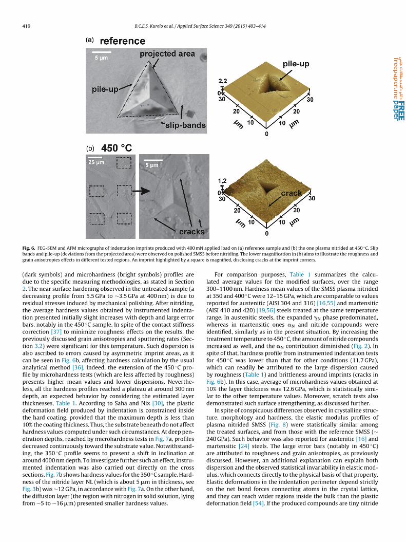
Images of typical indentation imprints, produced at the final400 mN applied load, are presented in Fig. 6 for the referencesample and the one nitrided at 450 ◦C. On the untreated sur-face, the indentation residual depth was about 2 �m; the surfacearound indentations presents slip bands and some pile-up pro-cess (inner material plastically displaced to the imprint edges).The imprint inspection after plasma nitriding clearly showed evi-dences of surface hardening. A half reduced residual depth wasobserved, whereas the surface sink-in took place at the indenta-tion edges. Sink-in correlates with the material’s ability to undergostrain-hardening, whereas pile-up denotes the poor degree of suchproperty. Generally, the ratio between elastic modulus and yieldstrength is low for sink-in (as it is the case of strain-hardeningmetals or non-strain hardening materials such as ceramics) andlarge for pile-up (as observed in some metals) [54]. The imprintcorners, notably in the 450 ◦C sample, also presented radial cracks,denoting some brittleness of the top surface layer under loading.Such crack occurrence can be attributed to the formation of nitride
Fig. 7a presents hardness profiles of the reference and plasmanitrided surfaces. Differences among instrumented indentation
410 B.C.E.S. Kurelo et al. / Applied Surface Science 349 (2015) 403–414
F mN ab MSS bg uare i
(d2drttbcptacafipldtdt1hediamsnFtf
ig. 6. FEG-SEM and AFM micrographs of indentation imprints produced with 400ands and pile-up (deviations from the projected area) were observed on polished Srain anisotropies effects in different tested regions. An imprint highlighted by a sq
dark symbols) and microhardness (bright symbols) profiles areue to the specific measuring methodologies, as stated in Section. The near surface hardening observed in the untreated sample (aecreasing profile from 5.5 GPa to ∼3.5 GPa at 400 nm) is due toesidual stresses induced by mechanical polishing. After nitriding,he average hardness values obtained by instrumented indenta-ion presented initially slight increases with depth and large errorars, notably in the 450 ◦C sample. In spite of the contact stiffnessorrection [37] to minimize roughness effects on the results, thereviously discussed grain anisotropies and sputtering rates (Sec-ion 3.2) were significant for this temperature. Such dispersion islso ascribed to errors caused by asymmetric imprint areas, as itan be seen in Fig. 6b, affecting hardness calculation by the usualnalytical method [36]. Indeed, the extension of the 450 ◦C pro-le by microhardness tests (which are less affected by roughness)resents higher mean values and lower dispersions. Neverthe-
ess, all the hardness profiles reached a plateau at around 300 nmepth, an expected behavior by considering the estimated layerhicknesses, Table 1. According to Saha and Nix [30], the plasticeformation field produced by indentation is constrained insidehe hard coating, provided that the maximum depth is less than0% the coating thickness. Thus, the substrate beneath do not affectardness values computed under such circumstances. At deep pen-tration depths, reached by microhardness tests in Fig. 7a, profilesecreased continuously toward the substrate value. Notwithstand-
ng, the 350 ◦C profile seems to present a shift in inclination atround 4000 nm depth. To investigate further such an effect, instru-ented indentation was also carried out directly on the cross
ections. Fig. 7b shows hardness values for the 350 ◦C sample. Hard-
ess of the nitride layer NL (which is about 5 �m in thickness, seeig. 3b) was ∼12 GPa, in accordance with Fig. 7a. On the other hand,he diffusion layer (the region with nitrogen in solid solution, lyingrom ∼5 to ∼16 �m) presented smaller hardness values.pplied load on (a) reference sample and (b) the one plasma nitrided at 450 ◦C. Slipefore nitriding. The lower magnification in (b) aims to illustrate the roughness ands magnified, disclosing cracks at the imprint corners.
For comparison purposes, Table 1 summarizes the calcu-lated average values for the modified surfaces, over the range300–1100 nm. Hardness mean values of the SMSS plasma nitridedat 350 and 400 ◦C were 12–15 GPa, which are comparable to valuesreported for austenitic (AISI 304 and 316) [16,55] and martensitic(AISI 410 and 420) [19,56] steels treated at the same temperaturerange. In austenitic steels, the expanded �N phase predominated,whereas in martensitic ones �N and nitride compounds wereidentified, similarly as in the present situation. By increasing thetreatment temperature to 450 ◦C, the amount of nitride compoundsincreased as well, and the �N contribution diminished (Fig. 2). Inspite of that, hardness profile from instrumented indentation testsfor 450 ◦C was lower than that for other conditions (11.7 GPa),which can readily be attributed to the large dispersion causedby roughness (Table 1) and brittleness around imprints (cracks inFig. 6b). In this case, average of microhardness values obtained at10% the layer thickness was 12.6 GPa, which is statistically simi-lar to the other temperature values. Moreover, scratch tests alsodemonstrated such surface strengthening, as discussed further.
In spite of conspicuous differences observed in crystalline struc-ture, morphology and hardness, the elastic modulus profiles ofplasma nitrided SMSS (Fig. 8) were statistically similar amongthe treated surfaces, and from those with the reference SMSS (∼240 GPa). Such behavior was also reported for austenitic [16] andmartensitic [24] steels. The large error bars (notably in 450 ◦C)are attributed to roughness and grain anisotropies, as previouslydiscussed. However, an additional explanation can explain bothdispersion and the observed statistical invariability in elastic mod-ulus, which connects directly to the physical basis of that property.
Elastic deformations in the indentation perimeter depend strictlyon the net bond forces connecting atoms in the crystal lattice,and they can reach wider regions inside the bulk than the plasticdeformation field [54]. If the produced compounds are tiny nitride
B.C.E.S. Kurelo et al. / Applied Surface
Fig. 7. (a) The hardness profiles of reference and plasma nitrided SMSS. Darksymbols correspond to instrumented indentation results, whereas bright symbolsindicate microhardness test values. (b) Instrumented indentation carried out in thecross section area of the SMSS plasma nitrided at 350 ◦C, with the correspondinghardness values with respect to the distance from surface. The dashed line indicatesthe mean thickness of nitride (compound) and diffusion layers (NL + �NL).
Fig. 8. The elastic modulus profiles of reference and plasma nitrided SMSS. Both thelarge error bars and statistical invariability of elastic modulus can be understoodthrough the physical basis of the material’s elastic response – see text for details.
Science 349 (2015) 403–414 411
precipitates embedded inside martensite grains, or nitrogen atomsoccupying interstices, the residual stresses caused in their vicinityproduce an average elastic response that is only a deviation fromthat observed for the stress-relieved matrix. On the other hand,changes induced by ion nitriding (lattice distortion and nitride pre-cipitates) do affect twinning and dislocation gliding mechanisms,which are responsible for the material’s plastic deformation.
Based on these assumptions, and because nitride compoundswere identified in all working temperatures (Fig. 2), it is possi-ble to assert that the precipitate-dispersion hardening [34] is animportant effect at near surface of nitrided SMSS. In such a mech-anism, hard and small precipitates (� and �′) act as obstacles todislocation movement, increasing the material’s strength. Anotherpossible mechanism is the Cottrell atmosphere, in which intersti-tial N atoms (the �N phase) increase plastic strength by migratingto vacant sites around the dislocations and pinning them.
3.4. Nanoscratch
Fig. 9 presents typical scratch penetration profiles for the ref-erence sample and the sample plasma nitrided at 350 ◦C. Thesescratch tests were carried out with ramping load up to 400 mN.Samples nitrided in the remainder conditions (400 and 450 ◦C)presented similar profiles, that is, scratch grooves constrainedto the modified layers and shallower than the reference sam-ple. In addition, the maximum penetration depths were similarto those observed in nanoindentation imprints, Fig. 6, using thesame maximum load. In Fig. 9, after nitriding at 350 ◦C, the max-imum penetration depth was reduced 36% (from ∼2 to 1.3 �m),whereas the elastic recovery after unloading increased from 18%to 55%, which is in agreement with the presence of a strengthenedcase containing expanded phase and nitrides.
These results indicated a superior strengthening under scratchof SMSS by plasma nitriding as compared to AISI 304 and 316 steels[55]. Because of the severe irregularity in morphology, as shownin Fig. 4, the same profile analysis was not possible for the 400and 450 ◦C samples. To investigate further the nitriding effects onthe scratch resistance, grooves were qualitatively analyzed by FEG-SEM, as follows.
The grooves morphologies produced on nitrided SMSS, shownin Fig. 10, are completely different from that on the reference sur-face. As scratches on the reference sample were nearly straight,the sliding tip experienced lateral track deviations in the nitrided
Fig. 9. Penetration profiles recorded during scratch tests with constant loading upto 400 mN, and the residual profile of grooves, for the reference SMSS and the surfaceplasma nitrided at 350 ◦C.

412 B.C.E.S. Kurelo et al. / Applied Surface Science 349 (2015) 403–414
F d plasi up to
sanwNwirsiimr
tcogspitotist
ig. 10. FEG-SEM images of typical scratch grooves produced on the reference anmages indicate regions magnified below them. The applied load increased linearly
urfaces. Moreover, this anisotropy seems to be working temper-ture dependent. Similar behavior was also observed in plasmaitrocarburized austenitic steels [40]. Such result corroboratesith orientation-dependent anisotropies in the N-diffusion and-precipitates formation, as discussed in Section 3.2. The grooveidths were narrower on the hardened nitrided surfaces (reduc-
ng from 20 to ∼8 �m at the scratch middle region). As theeference sample’s groove was smooth, the grooves in nitridedamples were rough through the entire scratch lengths, suggest-ng the occurrence of a stick-slip mechanism, in which the tipnteraction with hard precipitates hinders its movement. The defor-
ation energy accumulates at the tip edge, so being suddenlyeleased.
Differently from the observed under normal loading (indenta-ion in Fig. 6), and in spite of the different loading rates, neitherracks nor chipping were noticed in scratch tests after nitriding –nly exception was the crushed grain boundary region, near theroove’s end in the 400 ◦C sample. Actually, scratches on nitridedamples disclosed ductile-like features, notably the occurrence ofile-up (material plastically removed to the track edges), which
ntensity seems to decrease from the reference to the 450 ◦C-reated surface. These discrepancies are understood on the basisf the different stress distribution in normal (indentation) and
angential (scratch) loading [54]. The plastic deformation field inndentation tests reaches deep regions, which, in plasma nitridedurfaces, constitute a graded texture of hard precipitates, intersti-ial nitrogen and residual stresses. On the other hand, the stressma nitrided SMSS at different working temperatures. Numbers in the entire tests 400 mN, for 600 �m length.
distribution in scratch tests also comprises tangential forces due tothe moving tip, so that plastic deformation is constrained aroundthe tip and at shallow depths.
4. Conclusions
Supermartensitic stainless steel HP13Cr was plasma nitrided attemperatures 350, 400 and 450 ◦C. The starting condition was a fullymartensitic microstructure, achieved by heat treatment at 1100 ◦Cand oil quenching. The nitriding process substantially changedthe surface morphology, microstructure, and tribo-mechanicalresponse as compared to the reference surface, as follows.
- Because of the synergistic effect of high diffusivity and low sol-ubility of nitrogen in the martensitic structure, nitride phases�-Fe2+xN (0 ≤ x ≤ 1) and �′-Fe4N were formed in all work-ing temperatures, in addition to nitrogen in solid solution(�N). Layers comprising nitrides and diffusion zones presentedthickness ranging from 16 to 61 �m, according to the treat-ment temperature. At the outermost surface, the crystallineorientation-dependent diffusion (the swelling phenomenon) andsputtering rates produced an irregular topography with averagedroughness about 400 nm for the highest working temperature.
- The surface hardness, measured by instrumented indentation,increased from 3.8 to ∼14 GPa in all the working temperatures.The elastic modulus presented no statistically significant dif-ferences as compared with the reference surface, with a value

B.C.E.S. Kurelo et al. / Applied Surface Science 349 (2015) 403–414 1
around 230 GPa. Such behavior is understood based on the different extent of plastic and elastic deformation fields (ruling hardness and elastic modulus measurements, respectively) inside the precipitate-cont ainin g texturized layers.
- Strengthening of the nitrided surfaces was also observed in scratch tests. Under tangential loading, a hardened-ductile like character was disclosed (groove widths reduced from 20 to ∼8 J.Lm), with no evidences of cracking, chipping or britt le frac- ture. In spite of singularities concernin g the different loading regimes, as in indentation tests, the precipitation hardening plays an important role in the SMSS scratch resistance.
- The results corroborate with the effectiveness of plasma nitrid- ing in the surface modification of supermartensitic stainless steels, supporting further studies in aspects of interest for this alloy.