applications of nanocomposites and woodfiber plastics … 1. ~ schematic of microcellular injection...
TRANSCRIPT

The Seventh International Conference on Woodfiber-Plastic Composites ~
Applications of Nanocomposites and Woodfiber Plastics for Microcellular Injection Molding
Lih-Sheng Turng, Mingjun Yuan, Hrishikesh Kharbas, Herman Winata, and Daniel F. Caulfield
Abstract The paper reviews the processing advantages
and challenges of microcellular injection molding and presents recent research results on applica- tions of nanocomposites and woodfiber-plastic composites as well as new process develop for the microcellular injection molding process. In particular, two types of polyamide (PA-6) neat res- ins and their filled counterparts, such as a PA-6/ montmorillonite nanocomposite, a cellulose-fi- ber-reinforced PA-6 composite, and a hybrid PA- 6/cellulose/Wollastonite composite, were injection molded into ASTM test-bar samples with both conventional and microcellular injection molding. These molded samples were then subjected to scanning electron microscope analysis, tensile testing, and impact testing to study how the pro- cess conditions and micro-hano-fillers affect the
Turng: Assistant Professor/Co-Director, Polymer Engineering Center
Graduate Research Assistants, Dept. of Mechanical En- Yuan, Kharbas, Winata:
gineering, University of Wisconsin-Madison Caulfield:
Research Chemist, USDA Forest Service, Forest Prod- ucts Laboratory, Madison, Wisconsin, USA ~
microstructure and mechanical properties of the microcellular injection molded components. For all the materials studied, the microstructure and the mechanical properties of the molded samples were found to be strongly dependent on the pro- cess conditions and presence of the filler systems. Finally, initial results of a novel co-injection mold- ing process that combines the aesthetic and pro- cessing advantages of injection molding with the property attributes and benefits of microcellular plastics are presented.
Introduction
Microcellular Injection Molding Microcellular injection molding (also commer-
cially known as the MuCell process) can produce parts with excellent dimensional stability using lower injection pressure, shorter cycle time, and less material. This process blends “supercritical” fluid (usually nitrogen or carbon dioxide) with polymer melt in the machine barrel to create a sin- gle-phase polymer-gas solution. During the mold- ing process, the gas emerges from the melt form- ing numerous microcells. The size and density of microcells depend strongly on the process condi- tions and the material system. The typical cell di- ameter is in the order of 10 to 100 microns. While
Turng et al. ~ 21 7
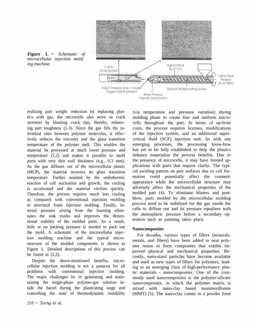
Figure 1. ~ Schematic of microcellular injection mold- ing machine.
realizing part weight reduction by replacing plas- tics with gas, the microcells also serve as crack arrestors by blunting crack tips, thereby, enhanc- ing part toughness (1-3). Since the gas fills the in- terstitial sites between polymer molecules, it effec- tively reduces the viscosity and the glass transition temperature of the polymer melt. This enables the material be processed at much lower pressure and temperature (1,2) and makes it possible to mold parts with very thin wall thickness (e.g., 0.3 mm). As the gas diffuses out of the microcellular plastic (MCP), the material recovers its glass transition temperature. Further assisted by the endothermic reaction of cell nucleation and growth, the cooling is accelerated and the material vitrifies quickly. Therefore, the process requires much less cooling as compared with conventional injection molding or structural foam injection molding. Finally, in- ternal pressure arising from the foaming elimi- nates the sink marks and improves the dimen- sional stability of the molded parts. As a result, little or no packing pressure is needed to pack out the mold. A schematic of the microcellular injec- tion molding machine and the typical micro- structure of the molded components is shown in Figure 1. Detailed descriptions of this process can be found in (2,3).
Despite the above-mentioned benefits, micro- cellular injection molding is not a panacea for all problems with conventional injection molding. The major challenges lie in generating and main- taining the single-phase polymer-gas solution in- side the barrel during the plasticating stage and controlling the state of thermodynamic instability
218 ~ Turng et al.
(via temperature and pressure variation) during molding phase to create fine and uniform micro- cells throughout the part. In terms of up-front costs, the process requires licenses, modifications of the injection system, and an additional super- critical fluid (SCF) injection unit. As with any emerging processes, the processing know-how has yet to be fully established to help the plastics industry materialize the process benefits. Due to the presence of microcells, it may have limited ap- plications with parts that require clarity. The typi- cal swirling pattern on part surfaces due to cell for- mation could potentially affect the cosmetic appearance while the microcellular structure may adversely affect the mechanical properties of the molded part (4). To eliminate blisters and post- blow, parts molded by the microcellular molding process need to be stabilized for the gas inside the cells to diffuse out and its pressure equalizes with the atmospheric pressure before a secondary op- eration such as painting takes place.
Nanocomposites For decades, various types of fillers (minerals,
metals, and fibers) have been added to neat poly- mer resins to form composites that exhibit im- proved physical and mechanical properties. Re- cently, nano-sized particles have become available and used as new types of fillers for polymers, lead- ing to an emerging class of high-performance plas- tic materials - nanocomposites. One of the com- monly used nanocomposites is the polymer-silicate nanocomposites, in which the polymer matrix is mixed with nano-clay based montmorillonite (MMT) (5). The nano-clay comes in a powder form

with a mean particle size of 8 µm. Each powder contains thousands to more than a million 10 %, thick platelets, which have a much larger surface area (~750 m 2 /g) and an aspect ratio (>50) than conventional, macro-sized fillers. Because of the large surface-to-volume ratio and the layer orientation of the nano-fillers, polymer-silicate nanocomposites offer improved stiffness, heat re- sistance, barrier and flame retardation, and dimen- sional stability in two dimensions with a relatively small amount of nano-clay (<10%).
Recently, studies by the authors have shown that when a polyamide-6 (PA-6 or Nylon-6) nano- composite is mixed with the supercritical fluid prior to injection molding, a microcellular part with highly uniform and evenly distributed micro- cells can be produced. It is believed that the nano- fillers might have served as nucleating sites that promote a huge number of cells initially leading to such a microstructure throughout the molded part, even under a wide range of processing pa- rameter variation. Only with this kind of micro- structure can the mechanical properties of micro- cellular injection molded parts be preserved.
Cellulose Fiber Composites and Microcellular Injection Molding
In the last decade, woodfiber-plastics composite products, being from renewable resources, lighter weight, less abrasive, and, quite often, less expen- sive, have drawn awareness and interest from equipment and additive industries. However, it is well known that cellulose fibers are temperature sensitive. Therefore, the conventional methods for processing cellulose-filled thermoplastic compos- ites were limited to the use of low-melting com- modity thermoplastics such as polyethylene (PE), polypropylene (PP), and poly(vinyl chloride) (PVC). Recently, a novel method of low tempera- ture processing has been developed that enables compounding cellulosic pulp fibers as reinforce- ments in PA-6 and other high-melting engineering thermoplastics (12). However, when cellulose- filled PA-6 composites are subsequently injection molded, one can see significant “browning” effect on the parts as the processing temperature of PA-6 (around 240°C) causes thermal degradation in the cellulose fibers. Since the microcellular injection molding process allows material to be injected at a lower temperature, efforts were made to explore the processing benefits and property improve- ments of combining microcellular injection mold-
ing with cellulose-filled PA-6 composite and the hybrid PA-6/cellulose/Wollastonite composite.
Research Objectives The objectives of this study are to evaluate the
processing benefits of applying nanocomposites and cellulose fiber composites for microcellular injection molding as well as to study the effects of filler systems and key processing parameters on microstructure and part quality of the resulting microcellular injection molded components. In addition, efforts have been made to develop a novel co-injection molding process that combines the aesthetic and processing advantages of injec- tion molding with the property attributes and benefits of MCPs.
Experimental Set-up, Material Systems, and Analysis Procedures
A 150-ton TOYO injection-molding machine and an Arburg 55-ton two-color, co-injection mold- ing machine (both with MuCell capability) were employed for the molding experiments. Nitrogen gas was used as the physical blowing agent in the experiments as it tends to generate finer micro- cells in injection molded parts. Experiments were performed based on several design of experiments (DOE) fractional orthogonal design matrices (4,6,9). Based on the DOE, ASTM D638 tensile samples were molded at various supercritical fluid (SCF) levels, melt temperatures, shot sizes, melt plastication pressures (MPP), and injection speeds. The rationale of using DOE is to under- stand the effects of various processing parameters on the microstructure and mechanical properties of the molded samples with relatively less molding trials. Two different types of PA-6 base resins with different filler systems, e.g., polymer-silicate poly- amide (PA-6) nanocomposites, cellulose-filled PA-6 composites, and their neat-resin counter- parts were employed to study the effect of using micro-/nano-scaled fillers as nucleating agents to control the size, density, and distribution of micro- cells. The molded samples were then subjected to scanning electron microscope (SEM) testing, transmission electron microscope (TEM) testing, x-ray diffraction analysis (XRD), tensile testing, impact testing, and dynamic mechanical analysis (DMA). Detailed descriptions of these DOE matrices and more complete test results can be found in other papers presented elsewhere (6-8).
Turng et al. ~ 219

Figure 2. ~ (Top) A “compos- ite” SEM micrograph. (Bot- tom) Averaged cell sizes in two perpendicular directions across the diameter of the spruce.
Microstructure of Microcellular Injection Molded Parts
The microstructure of microcellular injection molded parts depends on many factors, such as the number of nucleation sites (homogeneous ver- sus heterogeneous nucleation), process conditions (e.g., SCF level, pressure drop rate, etc.), strength and molecular structure of the matrix, as well as growth and coalescence of microcells during molding. Figure 2, top is a “composite” SEM mi- crograph showing the microstructure of a neat PA resin at a cross section of the spruce near the ma- chine nozzle. Several SEM micrographs were combined to show the change of cell size and dis- tribution across the diameter of the spruce. The measured microcell sizes in two orthogonal direc- tions are plotted in Figure 2, bottom. Microcells of varying sizes can be found throughout the cross section except near the part surface where there is a thin, non-cellular polymer skin layer (typically in the order of hundreds of microns). The reason for the solid skin layer could be attributed to the gas diffusion near the part interface and the growth of the gas cell being hampered by the rapid cooling of the material near the surface. A mathematical model that takes into account the temperature/ pressure histories of polymer melt during cooling and the cell growth of supercritical gas has been developed to predict the solid layer thickness and cell size distribution (8).
To demonstrate the effect of process conditions on the microstructure of the molded parts, Figure 3 shows some representative SEM micrographs near the center of the test bar sample for micro- cellular PA nanocomposite samples molded under
Figure 3. ~ SEM micrographs of the microcellular PA 6 nanocomposite molded under different process condi- tions, which result in different cell sizes and densities.
different conditions. The results obtained so far in- dicate that variations in process parameters, such as melt temperature, SCF level, injection speed and pressure, and shot size, can drastically affect the cell size, density, and distribution and, hence, the strength and the quality of the injection-
220 ~ Turng et al.

molded parts. In general, the cell size strongly de- pends on the shot size and moderately decreases with increasing SCF level, injection speed, and MPP, and increases with melt temperature, whereas the cell density is generally inversely pro- portional to the cell size. Since the effects of pro- cess conditions are intertwined in the DOE de- signs, further studies with refined DOE and different material systems are needed to develop guidelines of optimal processing windows to effectively control the microstructure of the molded parts.
In the past, significant research has been car- ried out on controlling the cell size and cell density of microcellular parts using micro-scaled fillers. One of the on-going studies by the authors focuses on the effect of nanoclay fillers (as in polymer-sili- cate nanocomposites) on the microstructure of microcellular PA-6 components (6,9). The study shows that, at higher weight reductions (e.g., 20% or higher), the presence of exfoliated nanoclay platelets can increase the density of cells by one or- der of magnitude and reduce cell-size signifi- cantly. For example, Figure 4 compares the SEM micrographs of the microcellular injection molded PA nanocomposite and its neat resin counterpart. The samples were molded under the same process conditions at 20 percent weight reduction. The mi- crograph for the nanocomposite shows a near “ideal” microstructure with highly uniform and evenly distributed microcells. This result suggests a feasible way of using nanoclay to effectively control the nucleation and growth of microcells.
It was also found that the nanoclay helps to facil- itate gas dissolution into the polymer melt and, thus, increase the level of weight reduction (9). More specifically, the maximum achievable weight reduction with the neat PA resin is 25 percent, be- yond which molding problems will occur with the excessive SCF inside the injection barrel. How- ever, a 31 percent weight reduction could be ob- tained with its nanocomposite counterpart. More- over, the addition of gas also helps to further disperse the nanoclay platelets in the polymer-gas solution, according to the XRD data with PA-6 nanocomposites (6). Evidently, multiple, synergis- tic benefits can be realized by combining micro- cellular injection molding with nanocomposites. Table 1 summarizes the general effect of process conditions and fillers on the cell size and mechani- cal properties of microcellular injection molded
Figure 4. ~ SEM micrographs of the microcellular PA 6 nanocomposite (top) and neat PA 6 resin (bottom) molded under the same process conditions. Effect of nanoclay fillers on the cell size and density can be seen.
parts. The exact behavior will undoubtedly de- pend on the individual material and process conditions used.
Mechanical Properties of Microcellular Injection Molded Parts
The mechanical properties are closely related to the microstructures and the weight reductions obtained by the presence of gas (4,10,11). This sec- tion discusses the effects of process conditions and filler system on the tensile, weld-line, and impact strengths of microcellular injection molded parts.
Tensile Strength A number of materials systems, namely, PA-6
nanocomposites, PA-6 neat resins, PA-6 with 28 wt. % wood cellulose fibers, PA-6/cellulose/ Wollastonite composite, polycarbonate (PC), have been employed to study the tensile strengths of the microcellular injection molded parts and com- pared with those of solid parts. For the materials systems studied, the addition of gas tends to bring
Turng et al. ~ 221

Table 1. ~ General effect of process conditions and fillers on the cell site and mechanical properties of microcellular injection molded parts. a
Dependent variables
Control variables Cell size Tensile strength Impact strength Weld-line strength increase Melt temperature increase decrease decrease
SCF level decrease increase inconclusive inconclusive Injection speed decrease increase increase increase MPP level decrease increase increase inconclusive Shot size decrease increase increase increase Micro-/nano-fillers decrease increase decrease inconclusive
a Dependent variable increases/decreases with increasing control variable, I: Inconclusive based on the available data.
about a reduction in the ultimate tensile strengths and the ductility/brittleness depends on the pro- cess conditions used (Fig. 5). The presence of the reinforcing fillers, on the other hand, improves tensile strength. For instance, tensile strengths in nanocomposites and cellulose-filled composites are higher than those observed with neat-resin samples (6,7). Based on testing results, higher shot sizes and MPP, which increase the amount of poly- mer in the component, increase the tensile strengths. The SCF levels and melt temperatures also have an important effect on the tensile strengths. The highest tensile strengths for PA 6 resins have been observed at the highest levels of shot size, MPP, injection speed, and SCF level and at the lowest level of melt temperature.
Impact Strength The impact test results with solid nanocom-
posites and cellulose-filled composites show that the addition of micro-hano-scaled fillers reduces the impact strength of the filled materials. How- ever, with microcellular injection molding process, an improved toughness has been observed with the nanocomposite as well as the neat PA resins (Fig. 6). Nevertheless, the impact test results with microcellular, cellulose-filled composites exhibit comparable or lower impact strengths compared with its solid counterparts (7). Such a reduction of impact strength is probably due to the presence of microcells at the interface between the cellulose fi- bers and the reinforcing cellulose fibers (Fig. 6). Recall that the fillers (e.g., nanoclay or cellulose fi- bers) could serve as nucleating sites (a phenome- non known as heterogeneous nucleation) that promote cell nucleation and growth at the polymer- fiber interface. For nanocomposites, the size of the nanoclay platelets is at least two orders of magni-
222 ~ Turng et al.
Figure 5. ~ Tensile stress-strain curves for different samples.
Figure 6. ~ SEM micrograph of microcellular PA-6/ cellulose fibers composite showing microcells sur- rounding the fibers.

Figure 7. ~ Browning effect of injec- tion molded cellulose-filled PA-6 parts.
tude smaller than that of the microcells (Fig. 3). Hence, the material properties in the polymer ma- trix are hardly affected by the microcells. Never- theless, this is not the case with the cellulose-filled composite, for which the microcells and diameter of cellulose fibers (~20 microns) are of comparable sizes. When the fibers are separated from the poly- mer matrix by the microcells as shown in Figure 6, the reinforcing effect of fibers reduces. Accord- ingly, the impact strength decreases.
Weld-Line Strength As a result of less material usage, absence of
high packing pressure, and lower processing tem- perature, the weld-line strength of microcellular components is lower than its solid counterparts and is significantly dependant on the process con- ditions (4). In particular, the weld-line strength of microcellular injection molded components in- creases with increasing melt temperatures, shot- size, and injection speed and is weakly dependant on the SCF level. Optimizing the process condi- tions can minimize the adverse effects of weld- lines on the part performance and surface appearance.
Experimental Results with Cellulose-Fiber-Reinforced PA-6 Composite When the experiments were being conducted
with cellulose/PA-6 and PA-6/cellulose/Wolla- stonite composites, color changes in various sam- ple sets were observed. With the conventional in- jection molding process, the solid neat PA-6 sample exhibits a colorless, translucent appear- ance. However, with microcellular injection mold- ing, the sample color changes to white-opaque - presumably due to the increased light scattering caused by the presence of micro-scaled bubbles
(Fig. 7). On the other hand, the virgin raw cellu- lose/PA-6 composite pellets are originally a light cream color. When the cellulose/PA-6 composite is conventionally molded, the color of the material turned dark brown, suggesting some degree of thermal degradation of the wood cellulose fibers due to high processing temperature with PA-6. Note that the natural cellulose fibers can only be used with thermoplastics that are processed below 200°C. When the cellulose/PA-6 composite is pro- cessed with microcellular injection molding, tem- perature setting at Zone 3 was reduced from 232° to 216°C and the molded samples exhibit a much lighter-brown color (Fig. 7). The light-brown color of the microcellular cellulose/PA-6 composite sam- ple may suggest a reduction in thermal degrada- tion, since a lower processing temperature was employed. Nevertheless, the presence of micro- cells can also contribute to the lightening of the color.
It was also found that the cellulose fibers and the cellulose/Wollastonite fillers improve tensile strength and tensile modulus. In addition, the microcellular injection molded neat resin exhibits higher impact strength than that of the conven- tionally molded solid part. For the microcellular in- jection molded composites, the impact strength- to-weight ratio was comparable to those of the con- ventionally molded solid part. Due to the presence of microcells within the microcellular injection molded samples, a reduction in tensile strength was observed with both of the filled composites and neat resin. A fractographical study reveals that some of microcells were formed at the inter- face of cellulose fibers and the polymer matrix, which could have a significant effect on the me- chanical properties of the molded parts. A detailed
Turng et al. ~ 223

Figure 8. ~ (Top) Pictures of the cross sections of a co-injection molded part that contains a microcellular PS core sandwiched by clear, solid PS skin layers. (Bottom) Comparisons of microcellular co-injection molded parts and conventional co-injection molded parts (with red colored pigment).
discussion of the experimental results can be found in (7).
Microcellular Co-Injection Molding By integrating solid plastics with MCPs via co-
injection molding, synergistic benefits can be real- ized. Further, this process is a perfect candidate for recycling of post-consumer plastics. Figure 8 shows pictures the cross sections at the runner and cavity and the top view of a co-injection mold- ed part that contains a microcellular polystyrene (PS) core sandwiched by clear, solid PS skin lay- ers. Initial experimental results suggest that the resulting foamed microstructure strongly de- pends on the skin-to-core switch-over time and the variation of pressure inside the cavity. Ideally, this microcellular co-injection molding process enables components with class “A” surfaces and lightweight microcellular cores to be molded while eliminating the swirling patterns typical of micro- cellular injection molded parts on the surfaces.
Conclusions The process conditions and micro-hano-scaled
fillers have great influences on the microstructure
and, thus, the mechanical properties of micro- cellular injection molded components. In addition, initial results of a novel co-injection molding pro- cess, which has potential in producing parts with class “A” surfaces while reducing part weight, were presented.
Acknowledgments This research is partly supported by the Na-
tional Science Foundation (DMI-0116415 and DMI-0140396) and the Polymer Engineering Cen- ter (PEC) Industrial Consortium at UW-Madison. The author is grateful to Kaysun Corp., Forest Products Lab., RTP Company, and the Madison Group, for their support of this project.
References 1. Suh, N.P. 1996. Innovation in Polymer Process-
2. Turng, L.S. 2001. J. Injection Molding Tech. 5, No. 3, p.
3. Xu, J. and D. Pierick. 2001. J. Injection Molding Tech. 5,
4. Turng, L.S. and H. Kharbas. 2003. Polym. Eng. & Sci.
ing-Molding. J.F. Stevenson, ed. p. 93.
160.
No. 3, p. 152.
43, No. 1.
224 ~ Turng et al.

5. Okada, A., M. Kawasumi, A. Usuki, Y. Kojima, T. Kur- auchi, and O. Kamigaito. 1990. Mater. Res. Soc. Proc., 171, 45.
6. Yuan, M., et al. 2003. SPE ANTEC Papers. 7. Winata, H., et al. 2003. SPE ANTEC Papers. 8. Hernandez, J.P., et al. 2003. SPEANTEC Papers. 9. Kharbas, H.A., P. Nelson, M. Yuan, L.S. Turng, and R.
Spindler. To be published in Polymer Composites.
10. Matuana, L.M., C.B. Park, and J.J. Balatinecz. 1998.
11. Xu, J., L. Kishbaugh, and M. Casale. 2002. SPE ANTEC
12. Sears, K., R.E. Jacobson, D.F. Caulfield, and J. Under-
13. Ramesh, N.S., D.H. Rasmussen, and G.A. Campbell.
Polym. Eng. & Sci. 38(11):1862.
Papers on CD-ROM.
wood. U.S. Patent # 6,270,883.
1994. Polym. Eng. Sci. 34, 1685.
Turng et al. ~ 225

Seventh International Conference on Woodfiber-Plastic Composites (and other natural fibers)
May 19-20, 2003 Monona Terrace Community & Convention Center Madison, Wisconsin, USA
Sponsored by the USDA Forest Service in cooperation with the American Chemical Society’s Cellulose and Renewable Materials Division, University of Wisconsin’s Polymer Engineering Center, University of Toronto, Materials & Manufacturing Ontario, and the Forest Products Society.
Hosted by the USDA Forest Service, Forest Products Laboratory.
Forest Products Society 2801 Marshall Court Madison, WI 53705-2295 phone: 608-231-1361 fax: 608-231-2152 www.forestprod.org