applications of distributed arithmetic to digital signal
TRANSCRIPT

Applications of Distributed Arithmetic to Digital Signal Processing: A Tutorial Review
Stanley A. White
ISTRIBUTED ARITHMETIC (DA) is so named because D the arithmetic operations that appear in signal pro- cessing (e.g., addition, multiplication) are not “lumped” in a comfortably familiar fashion (”Aha, there’s the multi- plier over there,” etc.), but are distributed in an often unrecognizable fashion. The most-often encountered form of computation in digital signal processing is a sum of products (or in vector analysis parlance, dot-product, or inner-product generation). This i s also the computa- tion that is executed most efficiently by DA.
Our motivation for using DA i s its extreme compu- tational efficiency. The advantages are best exploited in circuit design, but off-the-shelf hardware often can be configured effectively to perform DA. By careful de- sign one may reduce the total gate count in a signal pro- cessing arithmetic unit by a number seldom smaller than 50 percent and often as large as 80 percent.
HISTORICAL PERSPECTIVE OF DISTRIBUTED ARITHMETIC
The first widely known description of DA was given at a presentation by Abraham Peled and Bede Liu on IIR digi- tal filter mechanization in 1974 at the Arden House Work- shop on Digital Signal Processing. Their work on both FIR and I IR digital filter mechanization was also published in the / € E € ASSP Transactions [I ,2]. Earlier work (pre-1971) on DA had been performed in France by Croisier et al. [3]. The earliest documented work in the U.S. was done by Zohar [4,5,6], who had independently invented DA in 1968. Other early work in the United States was reported by Little [7]. From the Arden House description of DA, Bona and Terhan at Rockwell International designed an integrated-circuit DA compensator for control systems applications [8 ] , and White generalized its control system application [9]. The April 1975 special digital-signal pro- cessing issue of /€€€ Proceedings contained an article by Freeny on DA applications to the telephone system at Bell Laboratories [IO] and an article by White on general vector dot-product formation using DA [ I l l . Later that year White et al. developed an AGM digital autopilot based
4
I
IEEE ASSP MAGAZINE JULY 1 9 8 9
on DA 1121, Classen et al. at Philips in the Netherlands de- scribed communications systems applications [131, and Buttner and Schuessler at the University of Erlangen in Germany showed how to reduce the memory require- ments 1141. In 1975, Kai-Ping Yiu at Hewlett-Packard showed a conven ien t r u l e f o r h a n d l i n g t h e sign b i t [15]; H. Schroder of Siemens in Munich [I61 and C. S. Burrus of Rice University [I71 have given some suggestions and in- sight for speeding up the algorithms, and K. D. Kammeyer gave a survey/summary [181. Mechanization studies on application of DA to digital filters were discussed by Burrus [191, Jenkins and Leon [201, Zeman and Nagel 1211, Tam and Hawkins [22], Arjmand and Roberts [231 and White [24,251. Kammeyer [261 and Taylor [271 have pre- sented error analyses, Smith and White [28] have consid- ered DA for coordinate transformations, and Burleson and Scharf have applied it to a rotator array 1291. Taylor applied DA t o a Gray-Markel filter 1301, and Zohar dis- cussed a VLSl implementation of a correlator/filter [31]. DA i s also discussed by Taylor in his text [321, in the text by Smith and Denyer [33], and by Mintzer in Elliott’s handbook [341.
TECHNICAL OVERVIEW OF DISTRIBUTED ARITHMETIC
DA i s basically (but not necessarily) a bit-serial compu- tational operation that forms an inner (dot) product of a pair of vectors in a single direct step. The advantage of DA i s i t s efficiency of mechanization. A frequently argued disadvantage has been i ts apparent slowness because of i t s inherent bit-serial nature. This disadvantage i s not real if the number of elements in each vector is commensu- rate with the number of bits in each vector element, e.g., the time required to input eight 8-bit words one at a time in a parallel fashion i s exactly the same as the time re- quired to input (simultaneously on eight wires) all eight words serially. Other modifications to increase the speed may be made by employing techniques such as bit pairing or partitioning the input words into the most significant half and least significant half, the least significant half
0740-7467/89/0700-0004$1 .OO 0 1 9 8 9 IEEE

of the most significant half, etc., thereby introducing parallelism in the computation. This wil l be described in Section 4.
As an example of direct DA inner-product generation, consider the calculation of the following sum of products:
K
The Ak are fixed coefficients, and the xk are the input data words. If each xk is a 2's-complement binary number scaled (for convenience, not as necessity) such that (xkl < 1, then we may express each xk as
N-I
x k = -bko + bkn2-" (2) n=1
where the bkn are the bits, 0 or 1, bko is the sign bit, and b k . N - 1 i s the least significant bit (LSB).
Now let us combine Equations 1 and 2 in order to ex- press y in terms of the bits of x k :
y = k - 5 1 A,[-,,, f n=1 bkn2?] . ( 3 4
Equation 3a is the conventional form of expressing the inner product. Direct mechanization of this equation de- fines a "lumped" arithmetic computation. Let us instead interchange the order of the summations, which gives us:
This i s the crucial step: Equation 3b defines a distributed arithmetic computation. Consider the bracketed term in Equation 3b:
a one-bit-at-a-time (IBAAT) fashion, with LSBs { b k , N - l } first. The sign bits { b k O } are the last bits to arrive. The clock period in which the sign bits all simultaneously arrive is called the "sign-bit time." During the sign-bit time the control signal T, = 1, otherwise T, = 0. For the moment we will assume essentially zero time delay between the time of arrival of the address pattern to the ROM and the availability of its output. The delay around the accumulator loop is assumed to be one clock cycle and i s concentrated in the summer. Switch SWA remains in Position I except during the clock cycle that follows the sign-bit time, when it toggles for one clock cycle to Position 2, and the fully formed result is output.
We may reduce the memory size by half to a 2K word ROM by modifying the adder to an adderhbtractor and using T, as the addhubtract-control line as shown in Fig- ure 1 b. This configuration may now be mechanized with a 16-word ROM. The stored table is simply the upper half of Table 1.
The memory size may be halved again to f 2K words. In order to understand how this works, we shall interpret (not convert, but just interpret) the input data as being cast not in a (0 , l ) straight binary code, but instead as be- ing cast in a (-1,l) offset binary code. Suppose that we think of xk as
1 xk = y [ x k - ( - x k ) l (4)
and remember that in 2's-complement notation the nega- tive of x k i s written as
N-1 - - - X k = -bku + 2 bkn2-" -k 2-"-" (5)
n=1
(3c) where the overscore symbol indicates the complement of a bit. From Equations 2 and 5 we may rewrite Equation 4 as:
Because each bkn may take on vatues of 0 and 1 only, ex- pression (3c) may have only 2K possible values. Rather than compute these values on line, we may precompute the values and store them in a ROM. The input data can be used to directly address the memory and the result, i.e., the xf=lAkbkn, can be dropped into an accumulator. After N such cycles, the memory contains the result, y.
As an example, let K = 4, A, = 0.72, A, = -0.30, A3 = 0.95, and A4 = 0.11. The memory must contain all possible combinations (24 = 16 values) and their nega- tives in order to accommodate the term
which occurs at the sign-bit time. As a consequence, we need to use a 2 . 2K word ROM. Figure l a shows the simple structure (wi th a 2 x 24 = 32-word ROM) that can be used to mechanize these equations; Table 1 shows the contents of the memory. The T, signal is the sign-bit timing signal. We assume that the data on the x l , x, , x 3 , and x 4 lines (which with T, comprise the ROM address words) are serial, 2's-complement numbers. Each is delivered in
In order to simplify our notation later, it i s convenient to define the new variables
Ckn = bkn - E k n n # 0 (7)
and
Cko = -(bko - E k O ) (8)
where the possible values of the Ckn, including n = 0, are C1. Now (6) may be rewritten as
1 xk = ["f Ckn2-n - 2-(N-l) n - 0
By substituting (9) into (1) we obtain
N-1
= Q(bn)2-" + 2-"-"Q(O) (11 1 "=O
where
JULY 1989 IEEE ASSP MAGAZINE 5

K A Ak memory, a one-word initial condition register for Q ( O ) , and a single parallel adderhbtractor with the necessary control-logic gates. This i s shown in Figure IC, using the 8-word ROM, which contains the Q(b,).
Notice from the memory values of Table 2 that those values in the lower half under "Q" are the mirror image of the values i n the upper half, but with the signs re-
Q(bn) = k = l 2Ckn 2 and Q(o) = k=l - ' 2 ( I 2 )
Notice that Q(b,) has only 2'K-1' possible amplitude Val- ues with a sign that is given by the instantaneous corn- bination of bits. This is consistent with our earlier claim. The computation of y i s mechanized using a 2'K-1' word
Input Code
Ts b l n b2n b3n b4n
0 0 0 0 0 0 0 0 0 0 1 0 0 0 1 0 0 0 0 1 1
I 0 0 1 0 0 0 0 1 0 1 0 0 1 1 0
VI 0 0 1 1 1 - 0 1 0 0 0 0 1 0 0 1 0 1 0 1 0 0 1 0 1 1 0 1 1 0 0 0 1 1 0 1 0 1 1 1 0 0 1 1 1 1
(Table 1)
32-Word Memory Contents
A4 = 0.11 A3 = 0.95 A3+A4 = 1.06 A2 = -0.30 A2+A4 = -0.19 A2+A3 = 0.65 A2+A3+A4 = 0.75 A1 = 0.72 A1+A4 = 0.83 A1+A3 = 1.67 Al+A3+A4 = 1.78 A1+A2 = 0.42 A1+A2+A4 = 0.53 A1+A2+A3 = 1.37 Al+A2+A3+A4 = 1.48
= 0.72 = -0.30 = 0.95 = 0.11
Input Code
b l n b2n b3n b4n
0 0 0 0 0 0 0 1 0 0 1 0 0 0 1 1 0 1 0 0 0 1 0 1 0 1 1 0 0 1 1 1
1 0 0 0 1 0 0 1 1 0 1 0 1 0 1 1 1 1 0 0 1 1 0 1 1 1 1 0 1 1 1 1
Y
Figure la. Adder and Full Memory
8-Word Memory Contents, Q
-1/2(Al+Ap+A3+Aq) = -0.74 -1/2(Ai+A2+A~-Aq) = -0.63 -1/2(Al+A2-A3+Aq) = 0.21 -1/2(Al+Ap-A3-A4) = 0.32 -1/2(Ai-Ap+A3+Aq) = -1.04 -1/2(Ai -Ag+A~-Aq) = -0.93 -1/2(Al-Ag-A3+Aq) = -0.09 -1/2(Al-Ap-A3-A4) = 0.02
1/2(Al-A2-A3-A4) = -0.02 1/2(Ai-Ap-A3+Aq) = 0.09 1/2(Ai-Ag+As-A4) = 0.93 1/2(Al-Ap+A3+Aq) = 1.04 1/2(Ai+Ag-A3-A4) = -0.32 1/2(Al+Ap-A3+Aq) = -0.21 1/2(Al+Ag+A~-Aq) = 0.63 1/2(Ai+Ap+A3+Aq) = 0.74
16-Word
(Top Half of Table 1)
Sign Control
1 = Subtract 0 = Add
2-1
fo Figure 1 b. AdderlSubtractor and Memory
X1
8-Word Q(0) = -0.74
Table 2) Condition
ROM (Top Half of
x4
TS i Parallel Output
AIS sw0 C +
SWA @
2-1
e,
1 0 0 0 1 0 0 0 1 0 0 1 1 0 0 1 1 0 1 0 1 0 1 0 1 0 1 1 1 0 1 1 1 1 0 0 1 1 0 0 1 1 0 1 1 1 0 1 1 1 1 0 1 1 1 0 1 1 1 1 1 1 1 1
0 1 0 1 0 1 0 1 0 1 0 1 0 1 0 1
0 -A4 = -0.11 -A3 = -0.95 -(A3+A4) = -1.06 -A2 = +0.30 -(A2+A4) = +0.19 -(A2+A3) = -0.65 -(Az+A3+Aq) -A1 = -0.72 = -0.75
-(A1 +A4) = -0.83 -(Ai+A3) = -1.67 -(Al+A3+A4) = -1.78 -(A1 +Ap) = -0.42 -(A1 +A2+A4) = -0.53 -(Al+A2+A3) = -1.37 - ( A I + A ~ + A ~ + A ~ ) = -1.48
Table 2
Y
Figure IC . AdderlSubtractor and Reduced Memory
Figure 1. DA mechanization of y = Alxl + A2x2 + A3x3 + A4x4 for bit serial [I BAATI implementation.
6 IEEE ASSP MAGAZINE JULY 1989

versed. If we look at the bit patterns in the left-hand col- umn, we discover that if we EXOR b,, with the remaining set of b2n, b3,, and b+,, we properly address the 8-word memory to pull out the correct values of Q . . .except for the sign. By using the b,, as the addhubtract control line for the accumulator input, we also now have the proper sign. During the sign-bit time the addhubtract command must be inverted. We therefore combine the bl, and T, signals through an EXOR gate in order to derive the proper addkubtract control signal.
The initial-condition memory that contains the value Q(0) i s shown on the extreme right side of Figure IC. When the LSBs of the x k are addressing the ROM, the value that is read out from the ROM must be corrected by the Q(0) through switch SWB, which operates synchronously with switch SWA. This artifact of the binary-offset system can be seen in Equation 11. Subsequerlt values from the ROM are summed with the shifted previous sum. As before, we assume zero time delay between the application of the addressing bits and the availability of the contents of the ROM. There i s a clock period of delay through the parallel adder, and the switches SWA and SWB are in Position 2 only for the clock cycle following the sign-bit time when T, = 1. During the first clock cycle, the first output from the ROM, Q(bN-l), i s summed with Q(0); during the second clock cycle it i s right shifted and summed
during the third clock cycle i t is again right shifted and summed with Q(bN-3) to produce Q(bN-3) + Q(bN-,)2-' + lQ(bN-7) + Q(0)12-2; up to the Nth clock cycle when we add
with Q(b~-2) to produce Q(b~-2) + [Q(bN-1) f Q(O)12-';
Q(b,) to the right shifted previously computed quantity t o p r o d u c e Q(b, ) + Q(b,)2- ' + Q ( b , ) 2 - 2 + + Q(b~-2)2-'"-~' + [Q(bN_,) -t Q(0)l2-"-".
INCREASING THE SPEED OF D A MULTIPLICATION
One can see that ingesting the data serially, 1 BAAT, re- sults in a slow computation. If the input words are N bits in length, N clock cycles or periods are required in which to form the dot product. On the other hand, the equiva- lent of K separate products are being formed. If, therefore, K > N, the DA processor is faster than a single parallel m u I t i pl ier/accu m u lator.
Additional speed may be bought in two ways; one at the expense of linearly increased memory plus more arith- metic operations, the other at the expense of exponentially increased memory. The speed may be increased by a fac- tor of L by partitioning each input word into L subwords ( L must be a factor of N ) . This effectively increases the dimension of the input vector by a factor of L. We can use L-times as many memories with an expanded-capacity accumulator for combining their results, or we can stay with a single memory, but its word capacity becomes 2KL and the lengths of the words grow by log, L bits. The first approach is obvious and is shown in Figure 2. The second i s described below. Both are illustrated by example.
We seek a computationally simple means to introduce parallelism in the mechanization of Equation 11. The sum- mation over n i s next broken into two sums: the one over n sums from 0 to (NIL) - 1, and the second one sums I
Least-Significant Members of Bit Fairs \
I t I ' r I
Y
Figure 2. 2-Memory, 2 BAAT version of Figure I C.
JULY 1989 IEEE ASSP MAGAZINE 7

from 0 to L - 1. Now Equation 11 becomes:
where K L-1 4
and
Only NIL rather than N clock times are required to form the inner product, therefore the reader can see that we have succeeded in increasing the speed of the computa- tion by a factor of L .
We can parametrically explore the issue further. The total number of bits to be loaded is NK, and the number of clock periods required to read in these NK bits is NIL clocks. The number of input lines is
NK
(N/L) - K L . (16) - total bits in
= number of clock periods
There may be a relative cost
importance of minimizing pins importance of minimizing time
W =
We can solve this for L, the number of bits at a time (per input variable) that we are trying to load:
The Gauss brackets tell us to round up to the next integer. DA i s often most efficient when the number of input lines i s commensurate with the number of clocks required to load the data, or equivalently, when w = 1. For our example
therefore, the data will be input 2 BAAT. Of each input bit pair, we identify the most significant bit (MSB) and the least significant bit (LSB). For all values of L, the gate at which the most significant bit appears receives special treatment. The T, control signal is EXOR’d with the MSB for sign-bit time correction (because the sign bit i s the MSB of the word). In Figure 3, we can see the configura- tion and also see that the LSB of the input pairs of x, con- trols the addhubtract line.
In order t o demonstrate the validity of the approach, let us reconstruct by the same rules the structure for L = 1, as shown in Figure 4. Because for L = 1, a IBAAT serial input line for each x k uses the same line for the sign bit as for all other bits, all T, correction must be EXOR’d with all xk. The equivalence between Figures IC and 4 should be easy for the reader to see because the ROM
TS
Y
Figure 3. Single-memory, 2 BAAT version of Figure 1 C.
8 ~EEE ASSP MAGAZINE JULY 1989

x2
1 , I
1 , , b
8 1 , Word
i D ROM * I
I b - 0.74 1 , 9
SWB AIS 1 ,
0
1 , , b
8 1 , Word
i D ROM * I
1 , t I FD AIS
b
( * ' 1 ,
PIC
- 0.74
Y
Figure 4. DA mechanization of y = Alxl + A2x2 + A3x3 + &x4 for 1 BAAT mechanization similar t o Figure A3 showing alternate derivation of AIS (AddISubtractl control.
address line in Figure 4 that is driven byxk (k = 2,3,4) ac- tually sees x k @ T , @ ( T , @ x,) = x k @ x,. This i s the same as in Figure IC. The derivation of the A/S control lines is the same in both figures.
In Figure 5 , we see a demonstration of an L = 4 design in order to show the structure. The memory cost is ex- tremely great for such a small computation, but it i s pre- sented to illustrate the principle. Some more practical cases are shown below.
APPLICATION OF D A T O A BIQUADRATIC DIGITAL FILTER (AN EXAMPLE OF VECTOR DOT-PRODUCT A N D VECTOR-MATRIX-PRODUCT MECHANIZATION)
A typical biquadratic digital filter has a transfer function of the form
Y(z) - A. + A,z-' + A2z-'
X(z) 1 + B,z-' + B , z - ~ (20)
where the poles are determined by the B, and B,, and the gain and zeros are determined by the Ao, A,, and A,. The time-domain description is
- -
Y" = [&Ai A2 Bi BJ'[X,X,-~X,-~Y~-~ y1-J (21)
where the coefficient vector i s [A,A, A2 B, B21J and the data vector is [x,x,-,x,-~ yn-, yn-21r. A direct DA mechanization of the fi l ter i s shown in Figure 6. Notice the extreme economy of this filter. This figure differs slightly from those that we have seen above. We have a 5-dimensional
input vector to the addressing logic, but a scalar input, x,, and a scalar output, y, for the processor.
We have added a pair of delays (the z-' blocks) in the input-signal path so that we could develop the delayed signals, x,-, and x,-, from the input, x,; and we have added a third delay block so that we could develop the delayed output, y,-,, from y,-,. We obtain yn-, from a par- allel-to-serial register ( P E ) , since the output from the summer in the accumulator loop i s a parallel word. The contents of the 16-word ROM are shown in Table 3. We may, of course, use parallelism to increase the speed, as was discussed in the previous section.
There i s another important (because of low roundoff noise, low coefficient sensitivity and favorable limit-cycle behavior) form of digital f i l ter (the normal form) that serves t o illustrate the vector-matrix form of DA, and which we wil l now discuss. An excellent tradeoff study was recently presented by Barnes [351 to show how one could design a normal-form second order digital filter to meet prescribed performance criteria. In this section, an extremely eff icient set o f realizations i s shown, one in which the speed and complexity can be effectively traded. (Much of the fo l lowing i s taken f rom Refer- ences 36 and 37.)
A block diagram of the normal-form structure is shown in Figure 7. The multipliers b,, b2, c,, and c2 determine the pole locations of the filter. The input multipliers a, and a2 are used to determine the input scaling and the multipli-
9 JULY 1989 IEEE ASSP MAGAZINE

32K Word
I I '1 I,, I I AIS
~~~~
Ts
2-4=1/16
I@ Y
Figure 5. DA mechanization of y = Alx l + A2x2 + A3x3 + A4x4 for 4 BAAT implementation using single AdderlSubtractor and minimum memory.
ers a,, d,, and d, to determine the zero locations of the filter. There are nine multipliers in total, as compared to the five that are required in the so-called direct mechani- zation. Barnes shows procedures whereby one may re- duce this number of multipliers; however, we shall show how to eliminate them.
The vector matrix equation that describes the configu- ration of Figure 7 is given below:
The relationships between Equations 20 and 22 are
A,, = a,
A, = ald, + a,d2 - ao(hl + h2)
A2 = aO(hlhL - C l C J + al(c2d2 - M I )
( 2 3 ) + az(cid1 - hid,) B1 = h, + h2
62 = -bib2 + ~ 1 ~ 2 . U, = hi ~1 x,-i
(22) There are three common inputs to each of the "clumps" of Figure 7; so, for each output, we need to store 1 23 = 4 [;I 1 [:; &1 nl[::1
1 0 IEEE ASSP MAGAZINE JULY 1989

Contents of input Code *n- l a bn2 bng bn4 bng 16-Word Memory, Q
0 0 0 0 -1/2(Ao+Ai+Ap+Bi+B2) 0 0 0 1 -1/2(AO+A1+A2+B1-B2)
Xn-2 - L 4
xn 16
Word ROM
4 ,
TS
0 0 1 0 -1/2(Ao+Aj+Ap-B1+B2) 0 0 1 1 -1/2(Ao+Ai+Ap-B1-B2) 0 1 0 0 - I / ~ ( A o + A ~ - A ~ + B ~ + B ~ ) 0 1 0 1 -1/2(Ao+Ai-A2+81-B2) 0 1 1 0 - I / ~ ( A O + A ~ - A ~ - B ~ + B ~ ) 0 1 1 1 - I / ~ ( A o + A ~ - A ~ - B ~ - B ~ ) 1 0 0 0 - ~ / ~ ( A O - A I + A ~ + B ~ + B ~ ) 1 0 0 1 -1/2(Ao-Ai+Ap+Bi-Bp) 1 0 1 0 -1/2(Ao-Al+Ap-B1+B2) 1 0 1 1 - I / ~ ( A o - A ~ + A ~ - B ~ - B ~ ) 1 1 0 0 -1/2(Ao-Ai-Ap+Bi+B2) 1 1 0 1 -1/2(Ao-A1-Ap+BI-B2) 1 1 1 0 -1/2(Ao-Ai-Ap-BI+B2) 1 1 1 1 -1/2(Ao-Ai-A2-81-B2)

I 1
Figure 8. DA realization of state-space filter of Figure 7.
_J
~ - - - - - Yn
words. If the words that are stored are 16 bits long, then our three outputs together call for 3 x 16 = 48 bits per stored word. The total number of bits stored, however, is a modest 4 x 48 = 192. The somewhat detailed DA reali- zation is illustrated in Figure 8. Notice how the addressing section has reduced to a pair of EXOR gates. The 4-word by 48-bit memory is shown for clarity as comprising three memories. In fact, the ROM may physically consist of three identically addressed 4-word by 16-bit memories or a single 4-word extended length (48-bit) memory. Each 16-bit output segment drives a separate accumulator loop, each with its own initial-condition register, just as we en- countered earlier. The addhubtract control line is com- mon, and the outputs of two of the accumulator loops are converted to serial form in their parallel-to-serial reg- isters to be fed back to the memory addressing gates.
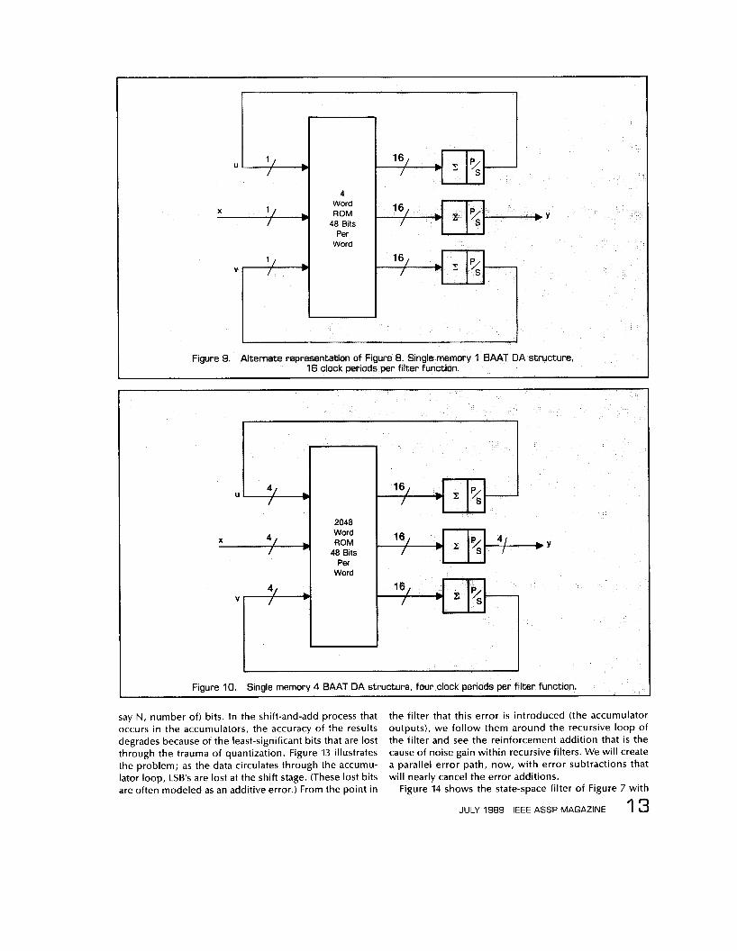
In order t o simplify our subsequent development, i t will be useful to redraw Figure 8 as shown in Figure 9. We can see the essence and utter simplicity of the structure, which is somewhat startling when one realizes that this is a realization of the 9-multiplier configuration of Figure 7.
Figure 10 shows a factor-of-four speedup over the cir- cuit of Figure 9 by using the data 4 bits at a time (4BAAT).
1 2 IEEE ASSP MAGAZINE JULY 1989
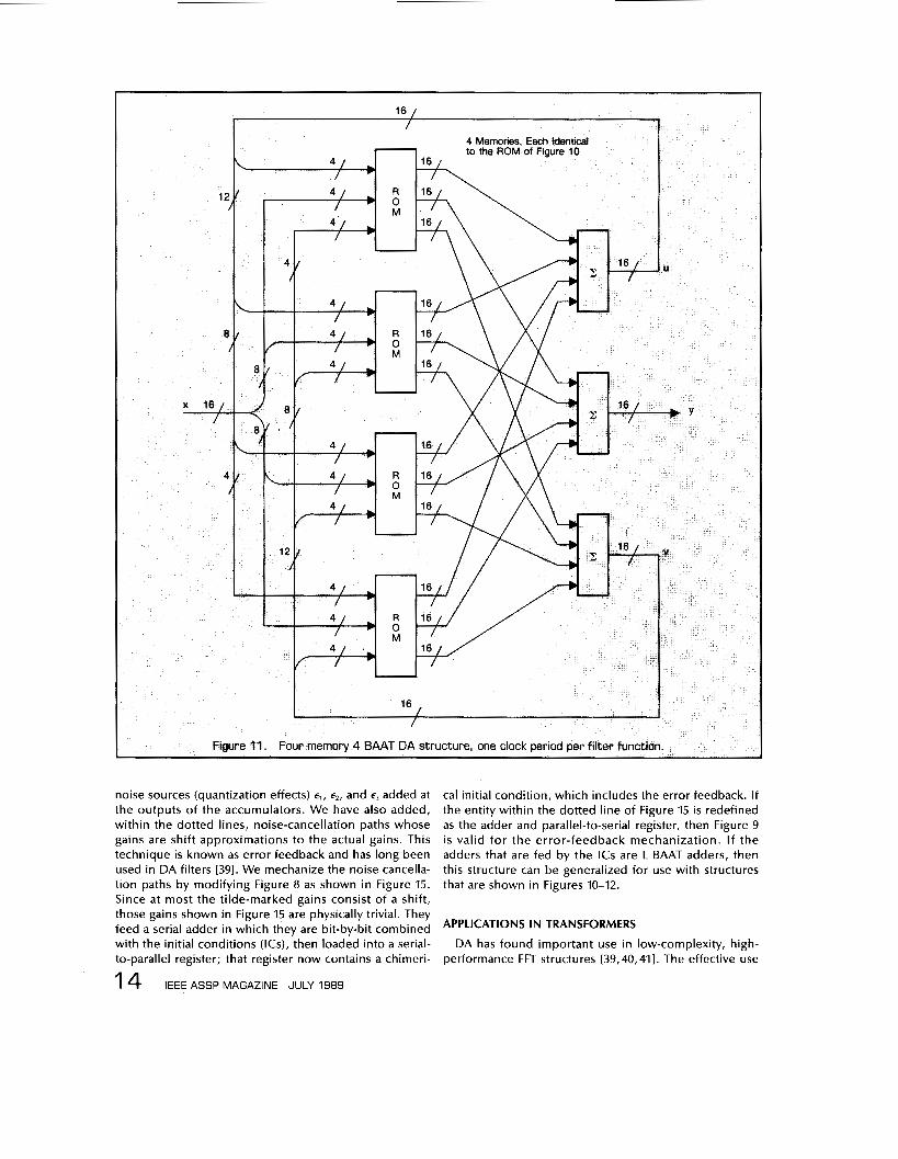
The parallel-to-serial registers shown do not output a serial data stream, but rather provide a sequence of four 4-bit wide segments. The time required to perform the filtering function has been reduced to 4 clock periods. This increase in speed demands that the ROM size be in- creased to (;) (23)4 = 2048 words. One would like to be able to make the throughput rate equal to the clock rate, rather than just a quarter of that rate. By quadrupling the memory of the configuration of Figure 10 and complicat- ing the 3 adders, we can create a very fast but memory- hungry (8K word by 48 bit) filter structure that can perform the filtering function in a single clock period, as shown in Figure 11.
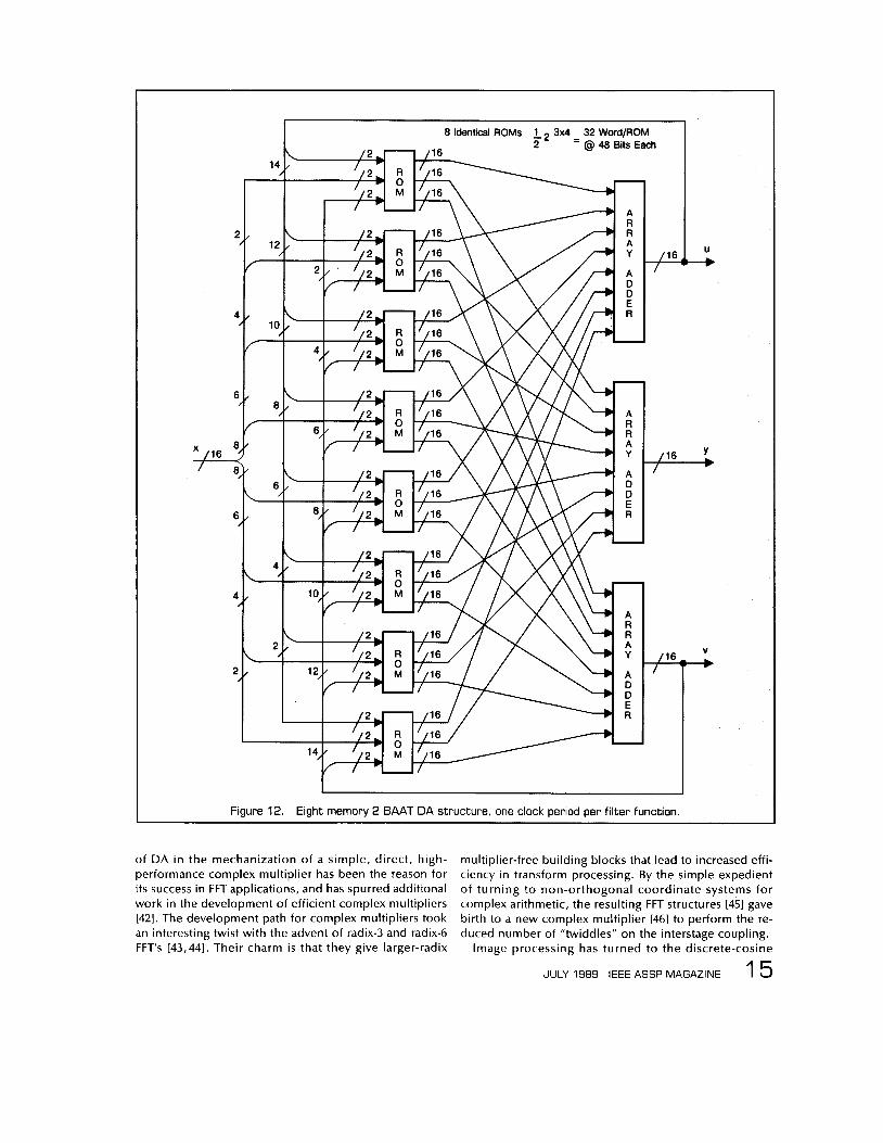
An alternate approach, which i s shown in Figure 12, may be used in which eight ROMs are addressed by the three data streams, 2 bits at a time (2BAAT). Each memory is now a more modest (23)2 = 32 words x 48 bits for a total memory requirement of 8 x 32 x 48 = 12,288 bits. The three adders are each of a complexity less than that of a 16-bit modified-Booth multiplier. In this approach, we have reduced the memory size at the expense of com- plicating the adders.
The outputs from the memories are 16 (or whatever,
X l / / I
Word ROM
48 Bits Per
Word
X 4/ / 1
2048 Word ROM
48 Bits Per
Word
Y
I I Figure I O . Single memory 4 BAAT DA structure, four clock periods per filter function.
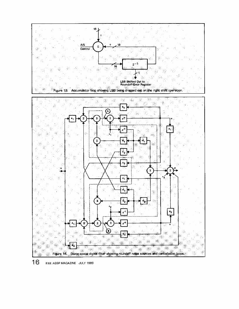
say N, number of) bits. In the shift-and-add process that occurs in the accumulators, the accuracy of the results degrades because of the least-significant bits that are lost through the trauma of quantization. Figure 13 illustrates the problem; as the data circulates through the accumu- lator loop, LSB's are lost at the shift stage. (These lost bits are often modeled as an additive error.) From the point in
the filter that this error i s introduced (the accumulator outputs), we follow them around the recursive loop of the filter and see the reinforcement addition that i s the cause of noise gain within recursive filters. We will create a parallel error path, now, with error subtractions that will nearly cancel the error additions.
Figure 14 shows the state-space filter of Figure 7 with
1 3 JULY 1989 IEEE ASSP MAGAZINE
noise sources (quantization effects) E , , c2, and e3 added at the outputs of the accumulators. We have also added, within the dotted lines, noise-cancellation paths whose gains are shift approximations to the actual gains. This technique is known as error feedback and has long been used in DA filters [391. We mechanize the noise cancella- tion paths by modifying Figure 8 as shown in Figure 15. Since at most the tilde-marked gains consist of a shift, those gains shown in Figure 15 are physically trivial. They feed a serial adder in which they are bit-by-bit combined with the initial conditions (ICs), then loaded into a serial- to-parallel register; that register now contains a chimeri-
1 4 IEEE ASSP MAGAZINE JULY 1989
cal initial condition, which includes the error feedback. If the entity within the dotted line of Figure 15 i s redefined as the adder and parallel-to-serial register, then Figure 9 i s valid for the error-feedback mechanization. I f the adders that are fed by the ICs are L BAAT adders, then this structure can be generalized for use with structures that are shown in Figures 10-12.
APPLICATIONS IN TRANSFORMERS
DA has found important use in low-complexity, high- performance FFT structures [39,40,411. The effective use
2
4
6
'/16
6 ,
4 I
2 1
U 1 Y
U M
1. Figure 12. Eight memory 2 BAAT DA structure, one clock period per filter function.
of DA i n the mechanization of a simple, direct, high- performance complex multiplier has been the reason for its success in FFT applications, and has spurred additional work in the development of efficient complex multipliers 1421. The development path for complex multipliers took an interesting twist with the advent of radix-3 and radix-6 FFT's [43,441. Their charm is that they give larger-radix
multiplier-free building blocks that lead to increased effi- ciency in transform processing. By the simple expedient of turning t o non-orthogonal coordinate systems for complex arithmetic, the resulting FFT structures [45] gave birth to a new complex multiplier [46] to perform the re- duced number of "twiddles" on the interstage coupling.
Image processing has turned t o the discrete-cosine
1 5 JULY 1989 IEEE ASSP MAGAZINE
I 6 IEE ASSP MAGAZINE JULY 1989

I-- I I I I I I I I I I I I I I I I
I I
I "n
Figure 15. DA mechanization of Figure 14.
transform (DCT) for more efficient processing. There, again, DA has found a home 147,481.
NONLINEAR AND/OR NONSTATIONARY PROCESSING WITH DA
We have only considered the use of DA in linear, time- invariant systems. It i s not so restricted. For variable coef- ficients, we may use RAM'S rather than ROM's. In fact, one of the trailblazers in this approach was Schroder [161.
In 1981 Cowan and Mavor [49] described an 8-tap adap- tive transversal filter that employed DA, and in 1983 an expanded version was published by Cowan, Smith, and Elliott [50]. Andrews [51] compared it favorably in a mech- anization study involving traditional and nontraditional arithmetic mechanizations of adaptive filters. The capac- ity of the DA adaptive structure can be increased by using block-processing concepts [52,531.
The mechanization of nonlinear difference equations by DA was presented by Sicuranza in 1541, who repre- sented the filter by a truncated discrete Volterra series. Chiang et al. in [551 report the results of a mechanization trade-off study of various implementations of quadratic filters. They conclude that DA i s as efficient as matrix decomposition implemented with systolic arrays, but that
DA lacks the modularity. Satisfactory DA adaptive nonlinear filters have been in-
vestigated and reported by Sicuranza and Ramponi [561, and by Smith et al. [57).
CONCLUSIONS
DA i s a very efficient means to mechanize computa- tions that are dominated by inner products. As we have seen, the coefficients of the equations can be time vary- ing, and the equations themselves can be nonlinear. When a great many computing methods are compared, DA has always fared well, not always (but often) best, and never poorly. As a consequence, whenever the perfor- mance/cost ratio is critical (especially in custom designs), DA should be seriously considered as a contender.
ACKNOWLEDGMENTS
I want to express my thanks to the many workers in the field who have quickly and generously shared their results with me; to my coworkers who, over the years, have pa- tiently simulated, analyzed, built, and tested endless DA concepts, and corrected my errors; and to the reviewers who offered very helpful suggestions and led me to refer- ences that were new and unfamiliar to me.
JULY 1989 IEEE ASSP MAGAZINE 1 7

REFERENCES
[ I ] A. Peled and B. Liu, “A New Approach to the Realiza- tion of Nonrecursive Digital Filters,” /€E€ Trans. Au- d i o a n d Electroacoust ics, Vo l . AU-21, N o . 6, pp. 477-485, December 1973.
[21 A. Peled and B. Liu, “A New Hardware Realization of Digital Filters,” / € E € Trans. on A.S.S.P., Vol. ASSP-22, pp. 456-462, December 1974.
[3] A Croisier, D. J. Esteban, M. E. Levilion, and V. Rizo, “Digital Filter for PCM Encoded Signals,” U.S. Patent 3,777,130, December 3, 1973.
[4] S. Zohar, ”New Hardware Realization o f Nonre- cursive Digital Filters,” / € E € Trans. on Computers, Vol. C-22, pp. 328-338, April 1973.
[SI S. Zohar, ”The Counting Recursive Digital Filter,” / € € E Trans. on Computers, Vol. C-22, pp. 338-347, April 1973.
[61 S. Zohar, “A Realization of the RAM Digital Filter,” / € € E Trans. on Computers, Vol. C-25, pp. 1048-1052, October 1976.
[7 ] W. D. Little, “A Fast Algorithm for Digital Filters,” / € € E Trans. on Communications, Vol. C-23, pp. 466- 469, May 1974.
[81 B. E. Bona and F. C. Terhan, “A Special-Purpose Digi- tal Control Compensator,’’ Proc. 8th Asilomar Con- ference on Circuits, Systems, and Computers, Pacific Grove, California, pp. 454-457, December 1974.
[91 S. A. White, “Applications of Digital Signal Process- ing to Control Systems,” Proc. 8th Asilomar Confer- ence on Circuits, Systems, and Computers, Pacific Grove, California, pp. 278-284, December 1974.
[IO] S. L. Freeny, ”Special-Purpose Hardware for Digital Filtering,” Proc. /€€E, Vol. 63, pp. 633-648, April 197.5.
[ I l l S. A. White, “On Mechanization of Vector Multipli- cation,” Proc. /E€€, Vol. 63, pp. 730-731, April 1975.
[I21 S.A. White, W. P. Engler, J. P. Davis, S. L. Smith, J.V. Henning, “A Programmable Digital Servo Control- ler,‘’ Invention Disclosure PF75E145, October 16, 1975.
[I31 T. R. C. M. Classen, W. F. G. Mecklenbrauker, and I . D. H. Peek, “Some Considerations on the Imple- mentation of Digital Systems for Signal Processing,” Philips Research Report 30, pp. 73-84, 1975.
I141 M. Buttner and H. W. Schuessler, “On Structures for the Implementation of the Distributed Arithmetic,” NTZ Communication Journal, Vol. 6, June 1975.
[I51 Kai-Ping Yiu, ”On Sign-Bit Assignment for a Vector Multiplier,” Proc. / € E € , Vol. 64, pp. 372-373, March 1976.
[I61 H. Schroder, “High Word-Rate Digital Filters with Programmable Table Look-Up,” /E€€ Trans. on Cir- cuits and Systems, Vol. CAS-24, No. 5, pp. 277-279, May 1977.
[I71 C. S. Burrus, ”Digital Filter Realization by Distributed Arithmetic,” International Symposium on Circuits and Systems, Munich, April 1976.
[I81 K. D. Kammeyer, ”Digital Filter Realization in Distrib- uted Arithmetic,” Proc. European Conf. on Circuit
1 8 ~ E E E ASSP MAGAZINE JULY 1989
Theory and Design, Genoa, Italy, September 1976.
[I91 C. S. Burrus, ”Digital Filter Structures Described by Distributed Arithmetic Filters,” / E € € Trans. on Cif- cuits and Systems, Vol. CAS-24, No. 12, pp. 674-680, December 1977.
1201 W.K. Jenkins, and B.J. Leon, “The Use of Residue Number System in the Design of Finite Impulse Re- sponse Filters,” /€€€ Trans. on Circuits and Systems, Vol. CAS-24, No. 4, April 1977.
[211 I . Zeman, and H.T. Nagle, Jr., “A High-speed Mi- croprogrammable Digital Signal Processor Employing Distributed Arithmetic,” /E€€ Trans. on Computers, Vol. C-29, No. 2, pp. 134-144, February 1980.
[22] B. S. Tam, and G. J. Hawkins, “Speed-Optimized Mi- croprocessor Implementation of a Digital Filter,” /€€€ Proc., Vol. 69, No. 3, pp. 85-93, May 1981.
1231 M. Ar jmand and R.A. Roberts, “ O n Comparing Hardware Implementations of Fixed-point Digital Fil- ters,“ / E € € Circuits and Systems Magazine, Vol. 3,
[241 S. A. White, “Architecture for a Digital Program- mable Image Processing Element,” Proc. 1981 /€€€ In- ternational Conference on Acoustics, Speech, and Signal Processing, Atlanta, pp. 658-661, March 30- April 1, 1981.
[25] S. A. White, “An Architectural for a High-speed Digi- tal Signal Processing Device,” Proc. 1987 / € € E Interna- tional Symposium on Circuits and Systems, Chicago, pp. 893-896, April 28-29,1981.
[26] K. D. Kammeyer, ”Quantization Error of the Distrib- uted Arithmetic,” / € € E Trans. on Circuits and Sys- tems, Vol. CAS-24, No. 12, pp. 681-689, December 1977.
[27] F. J. Taylor, “An Analysis of the Distributed-Arithmetic Digital Filter,” / € E € Trans. on A.S.S.P., Vol. ASSP-35,
[28] S. G. Smith and S. A. White, “Hardware Approaches to Vector-Plane Rotation,” Proc. 1988 / E € € Interna- tional Conference on Acoustics, Speech, and Signal Processing, New York, pp. 212-213, April 11-14,1988.
I291 W. P. Burleson and L. L. Scharf, “A VLSl Implementa- tion of a Cellular Rotator Array,” Proc. 1988 / € E € cus- tom integrated Circuits Conference, pp. 8.1.2-8.1.4.
[30] F. J. Taylor, “A Distributed Gray-Markel Filter,” I € € € Trans. on A.S.S.P., Vol. ASSP-31, No. 3, pp. 761-763, June 1983.
[311 S. Zohar, “A VLSl Implementation of a Correlated Digital Filter Based on Distributed Arithmetic,” /E€€ Trans. on A.S.S.P., Vol. ASSP-37, No. 1, pp. 156-160, Jan. 1989.
[321 F. I . Taylor, Digital Filter Design Handbook, Marcel Dekker, Inc., pp. 678-697, June 1983.
[33] S. G. Smith and P. B. Deyer, Serial-Data Computation, Kluwer Academic Publishers, 1988.
[34] D. F. Elliott (ed.), Handbook of Digital Signal Process- ing, Academic Press, pp. 964-972, 1987.
[351 C. W. Barnes, “A Parametric Approach to the Realiza- tion of Second-Order Digital-Filter Sections,” / E € €
NO. 2, 1981, pp. 2-8.
NO. 5, pp. 1165-1170, Oct. 1986.

Trans. on Circuits and Systems, Vol. CAS-32, No. 6, pp. 530-539, June 1985. S. A. White, “High-speed Distributed-Arithmetic Re- alization of a Second-Order Normal-Form Digital Fil- ter,“ l€€€ Trans. on Circuits and Systems, Vol. CAS-33, No. I O , pp. 1036-1038, October 1986. S. A. White, “High-speed Distributed-Arithmetic Re- alization of a Second-Order State-Space Digital Fil- ter,” Proc. 20th Asilomar Conference on Signals, Systems, and Computers, Pacific Grove, California, pp. 359-362, November IO-12,1986. T. L. Chang and S.A. White, “An Error Cancellation Digital-Filter Structure and Its Distributed Arithmetic Implementation,” /€E€ Trans. on Circuits and Sys- tems, Vol. CAS-28, No. 4, pp. 339-342, April 1981.
[501 C. F. N. Cowan, S. G. Smith, and J. H. Elliott, “A Digi- tal Adaptive Filter Using a Memory-Accumulator Ar- chitecture: Theory and Realization,” /E€€ Trans. on A.S.S.P., Vol. ASSP-31, No. 3, pp. 541-549, June 1983.
[511 M. Andrews, “A Systolic SBNR Adaptive Signal Pro- cessor,” /€€€/. Solid State Circuits, Vol. SC-21, No. 1, pp. 120-128, Feb. 1986.
[521 C. -H. Wei, and J. -J. Lou, “Multimemory Block Struc- ture for Implementing a Digital Adaptive Filter Using Distributed Arithmetic,” I€€ Proc., Vol. 133, Pt. G, No. 1, pp. 19-26, Feb. 1986.
[531 Y.-Y. Chiu and C.-H. Wei, “On the Realization of Multimemory Block Structure Digital Adaptive Filter Using Distributed Arithmetic,” 1. Chinese Institute o f Engineers, Vol. I O , No. 1, pp. 115-122, 1987.
[391 S. A. White, “A Simple FFT Butterf ly Ari thmetic Unit,” I€€€ Trans. on Circuits and Systems, Vol. CAS-
[401 I. R. Mactaggart and M.A. Jack, “A Single Chip Radix-2 FFT Butterfly Architecture Using Parallel Data Dis- tr ibuted Arithmetic,” /E€€ /. Sol id State Circuits, Vol. SC-19, pp. 368-373, June 1984.
1541 G.C. Sicuranza, “Nonlinear Digital-Filter Realization by Distributed Arithmetic,” /€€E Trans. on A.S.S.P.,
[551 H. -H. Chiang, C. L. Nikias, and A. N. Venetsanopou- I os, ” Efficient I m p I e m e n tat i o n s of Quad rat i c Digital Filters,” I € € € Trans. on A.S.S.P., Vol. ASSP-34, No. 6, pp. 1511-1528, Dec. 1986.
28, No. 4, pp. 352-366, April 1981. Vol. ASSP-33, NO. 4, pp. 939-1321, Aug. 1985.
S.A. White, “An Architecture for a 16-Point FFT GaAs Building Block,” Proc. 21st Asilomar Conference on Signals, Systems, a n d Computers, Pacific Grove, California, pp. 928-932, November 1987. S. G. Smith and P. B. Denyer, “Efficient Bit-Serial Complex Multiplication and Sum-of-Products Com- putation Using Distributed Arithmetic,” Proc. 1986
[561 G . L . Sicuranza, “Adaptive Nonlinear Digital Filters Us ing D i s t r i b u t e d Ar i thmet ic , ” /€E€ Trans. on A.S.S.P., Vol. ASSP-34, No. 3, pp. 518-526, June 1986.
[57] M. J. Smith, C. F. N. Cowan, and P. F. Adams, “Non- linear Echo Cancellers Based on Transpose Distrib- uted Arithmetic,” I € € € Trans. on Circuits and Systems, CAS-35, No. 1, pp. 6-18, Jan. 1988.
lnternational Conference on Acoustics, Speech, and Signal Processing, Tokyo, pp. 2203-2206, April 1986. E. Dubois and A. N. Venetsanopoulos, “A New Algo- r i thm for the Radix-3 FFT,” l€€€ Trans. on A.S.S.P., Vol. ASSP-26, No. 3, pp. 222-225, June 1978. S. Prakash and V.V. Rao, “A New Radix-6 FFT Algo- rithm,” l€€€ Trans. on A.S.S.P., Vol. ASSP-29, No. 4,
S.A. White, “Results of a Preliminary Study of a Novel IC Arithmetic Unit for an FFT Processor,” Proc. 18th Asilomar Conference on Circuits, Systems, and Computers, Pacific Grove, California, pp. 67-71, November 5-7,1984. S. A. White, “A Complex Multiplier for Binary Two’s- Complement Numbers,” U.S. Patent No. 4,680,727, July 14, 1987. N. Demassieux, G. Concordel, J. -P. Durandeau, and F. Jutand, “An Optimized VLSl Architecture for a Multiformat Discrete Cosine Transform,” Proc. 1987 I € € € Interngtional Conference on Acoustics, Speech, Signal Processing, pp. 547-550. A.M. Gottlieb, M.T. Sun, and T. C. Chen, “A Video Rate 16 x 16 Discrete Cosine Transform IC,” Proc. 1988 I € € € Custom Integrated Circuits Conference,
C. F. N. Cowan and J. Mavor, “New Digital-Adaptive Filter Implementation Using Distributed-Arithmetic Techniques,” I€€ Proc., Vol . 128, Pt. F, No. 4,
pp. 939-941, August 1981.
pp. 8.2.1-8.2.4.
pp. 225-230, Aug. 1981.
Stanley A. White (S’55, M’57, SM’69, F’82) was born i n Providence, Rhode Island in 1931. He i s Senior Scientist at Rockwell International Corporation’s Autonetics Electronics Systems i n Anaheim, California, and Adjunct Profes- sor of Electrical Engineering at the University o f California, Irvine. He received his B.S.E.E., M.S.E.E., and Ph.D. (wi th letter of commen- dat ion) degrees f r o m Purdue University i n 1957, 1959, and 1965, respectively. He i s also a
Fellow of the American Association for the Advancement of Science (AAAS) , the New York Academy of Sciences (NYAS), and the Insti- tute for the Advancement of Engineering (IAE). He i s a member (and long-t ime Autonetics Chapter President) o f Sigma Xi, Tau Beta Pi, the Audio Engineering Society, and has been International Director of Eta Kappa Nu. H e received the Purdue University Distinguished Engineering Alumnus Award in 1988, the Leonard0 Da Vinci Medal- l ion in 1986, and was selected as Rockwell International Engineer of the Year in 1985. In 1984 he received both the Engineer of the Year Award f r o m the Orange County (Cali fornia) Engineering Counci l and the I E E E Centennial Medal. He has held several distinguished lecturerships and received the NEC Distinguished Lecturer Award.
Dr. White has over 100 publications i n the open literature, holds 30 U.S. patents (wi th more pending issue), and is a registered Pro- fessional Engineer in bo th California and Indiana.
He i s General Chairman of ISCAS ’92; was General Chairman of ICASSP ’84, Vice Chairman of ISCAS ‘83; was both General Chair- man of the Asilomar Conference o n Circuits, Systems, and Computers, and Technical Program Chairman of the IEEE Region 6 Conference in 1982; and was Technical Program Chairman of the Asilomar Con- ference in 1981. Dr. Whi te is listed in American Men a n d Women of Science, Who‘s Who in Biomedical Engineering, Who‘s Who in Engi- neering, Who’s Who in America, Who‘s Who in The World, and other standard biographical reference works.
JULY 1989 IEEE ASSP MAGAZINE 1 9