applications electrical
TRANSCRIPT

8/19/2019 Applications Electrical
http://slidepdf.com/reader/full/applications-electrical 1/447

8/19/2019 Applications Electrical
http://slidepdf.com/reader/full/applications-electrical 2/447
P L I C A T I O N S
11
e c t r i c a
I
o n s t r u c t i o n
D E D I T I O N
K.
Clidero
th
H.
Sharp e
'
"3
•da

8/19/2019 Applications Electrical
http://slidepdf.com/reader/full/applications-electrical 3/447
Copyright © 1991 Irwin Publishing
No par t of this book may be rep rodu ced
or transm itted in any form or by any
me ans, electronic or m echanical, includ
ing photocopy, recording or any infor
mation storage and retrieval system now
known or to be invented, without per
mission in writing from the publisher
excep t by a reviewer wh o wishe s to
quo te brief passag es in con nec tion w ith
a review written for inclusion in a maga
zine,
newspaper, or broadc ast .
First Edition p ublish ed 1975
SI M etric Seco nd Edition pu blished 1979
Third Edition published 1991
Edited by Kate Revington
Designed by Jack Steiner G raphic Design
Typ esetting and illustrations
by Trigraph Inc.
Cover photograph by Birgitte Nielsen
Canadian Cataloguing in Public
Data
Clidero, Robert K.
Ap plications of electrical cons
3rd. ed.
Includes index.
ISBN 0-7725-1719-3
1. Electric engin eering. I. Sha rp
Kenneth H. II. Title.
TK452.C551991
621.3 C91-
ISBN-13:
978-0-7725-1719-7
ISBN-10: 0-7725-1719-3
Printed and bound in Canada
Published by
Nelson
1120 Birchmount Road
Toronto, Ontario M1K5G4
1-800-668-0671
www.nelson.com
8/19/2019 Applications Electrical
http://slidepdf.com/reader/full/applications-electrical 4/447

8/19/2019 Applications Electrical
http://slidepdf.com/reader/full/applications-electrical 5/447
CHAPTER 12:
Aluminum-Sheathed Cable/142
Construction, sizes, preparation,
installation techniqu es, and applications
CHAPTER 13:
Mineral-Insulated Cable/151
Sizes, preparation, handling, and
applications
CHAPTER 14:
Conduit Wiring/162
Rigid, flexible, thinwall, and plas tic
cond uit, tools, related eq uipm ent, sizes,
allied fittings, and regulations
CHAPTER 15:
Residential Service Wiring /199
Types, sizes, grounding, related
equipment, installation methods, and
regulations
CHAPTER 16:
Industrial Servic es/ 229
Wiring diagrams, 3 phase syste m s, 3 and
4 wire systems, m eter con nections,
grounding, circuit breakers, regulations,
ground fault protection d evices and
their operation
CHAPTER 17:
Fuses
/ 249
Types, sizes, and ratings
CHAPTER 18:
Residential Electric Heating / 266
Types, sizes, insulation, heat load
calculations and cost analysis
CHAPTER 19:
Discharge Light Sou rces/ 301
Fluorescent lighting; high-intensity
discharg e lamps, including the mercury
vapour, metal halide, and high-pressure
sodium; tungsten-halogen lighting; lamp
cons truction; circuit diagrams; and
applications; energy conservation and
lamp m aintenance
CHAPTER 20:
Mo tor Control / 334
Motor protection, across-the-line
starting, reduced voltage starting,
starte r construction and o peration,
magnetic starters, and circuit diagrams
for control circuits, overload protection
devices, typ es, and ratings
CHAPTER
21:
Fastening De vice s/ 376
Screw fasteners, wood and metal types,
bolt strength; masonry fasteners, types
and methods of installation; drilling
device s; hollow-wall fa steners ;
powder-actuated fasteners, associated
tools, acce ssorie s, and regulations
CHAP TER 22 :
Tools of the Electrical Trade / 406
Hand d river s; pliers; cutting, striking,
and m easuring too ls; safety devices;
pow er tools, electric and cordless typ es;
motor operation; power tool
maintenance, selection and users' safety
Glossary of Electrical Terms / 436
For Reference / 437
Inde x/ 438

8/19/2019 Applications Electrical
http://slidepdf.com/reader/full/applications-electrical 6/447
Preface
A
s classroom tea che rs, we are aware
of the need for student textual
materials that explain the non-mathe
matical theory behind electrical devices
and equipment.
Drawing on our experience as jour
neymen electricians and high school
teachers, we have aimed, in this text, to
explain as simply as possible modern
electrical products and their applica
tions in electrical c ircuits. We hav e also
tried to downplay the use of complex
technical terms and to em phasize th e
reason s for electrical installation pra c
tices. This
Third Edition
has been given
extensive review not only by us but b y
the manufacturers of illustrated prod
ucts. Always, our intent h as be en to p ro
vide read ers with th e most recen t and
up-to-date changes in product design.
Many chapte rs have been
lengthened by the insertion of new prod
uct and technolo gy information. New
illustrations provide a clear understand
ing of recent chang es in both technology
and w iring co de s. Also, a new cha pte r
(Chapter 22) provides read ers with a
fuller u nde rstan ding of the specialized
tools used in the electrical industry.
Since the electrical industry has not
yet adopted the SI (me tric) sys tem of
measurement, the commonly used impe
rial measure tables ap pea r with m etric
equivalents through out the text. The
text accurately reflects an industry in
transition.
It is our hope that high school stu
dents, appre ntices, electricians, and t he
genera l public will find th is tex t a useful
tool for understanding how electrical
theo ry is transla ted into practical term s.
We would like to than k all thos e per
sons and organizations who se co-opera
tion mad e this text poss ible.
Robert K. Clidero
Kenneth
H.
Sharpe

8/19/2019 Applications Electrical
http://slidepdf.com/reader/full/applications-electrical 7/447
E
lectrical power is supplied to the
hom e by th e local hydr o utility.
Because there are so many appliances
available today, two voltages are
needed. Lighting and receptacles for
such sm all appliances as radios, toast
ers, teakettles, frying pans, and electric
drills require a 120 V supply. Large
appliances, such as electric stoves,
clothes driers, some air conditioners,
and electric heaters, operate on 240
V
On the North American con tinent, a
frequency of 60 Hz (cycles) is th e s tan d
ard. The frequency of an alterna ting cur
rent sy stem is the num ber of pu lses of
current that pass along the con duc tors
in one secon d. On a 60 Hz system, there
are 120 pulses per seco nd. One p ositive
and one negative pulse make up one
cycle,
or
hertz.
(See Fig. 1.1) Residential
V2 I*:
cycle
negative
FIGURE
1.1
pulses
The Three
Wire
Distribution
System
voltages ope rate on a
single-phase
sys
tem. Both single-phase voltages com e
from a transfo rme r tha t h as a single pri
mary winding.
O btaining T wo Voltages
From T hree W ires
When two dry cell batteries of 1.5
V
each are connected in series, 3 V are
obtained. (See Fig. 1.2) By connecting a
wire midway betwee n th e two cells, a 3
wire system providing two voltages is
created. The distribution transformer
Three alternating current
FIGURE 1.2 Tw o voltages from 3 wires
Applications of Electrical Construction

8/19/2019 Applications Electrical
http://slidepdf.com/reader/full/applications-electrical 8/447
used to supply a house or group of
hou ses is wired in the s am e m anner.
Distr ibut ion Transformer
The local hydro utility use s
a
ser ies of
transformers to lower its voltage s in
stages from the power station
to
the res
idential street. Each locality may differ
slightly in the actual v oltage tha t arrives
at the distribution transformer on
the
street. One comm on voltage is 2400
V.
(See Fig.
1.3)
secondary
wind ing
live wire
—<
pr im ar y w ind ing
2400
V
^ T T x
^
r ound
.
neutral
w i r e
1 2 0 V — f - 1 2 0 V -
240 V
_ laminated
core
t ransformer
rat io 10:1
— l ive wire
FIGURE
1.3
Distribution transformer circuit
diagram
High-tension
(high-voltage)
lines
sup
ply the p rima ry coil
of
the transformer
with 2400
V
This transformer reduces
the voltage on
a
10:1 ratio , giving
a
secondary output of 240
V A
wire is con
nected to th e midway point of the secon
dary winding, dividing its 240 V in half.
This middle,
or
neutral, wire provides
two voltages on a 3 wire system.
The two outer w ires of the secon
dary winding are known
as
th e live
wires. It should be noted th at in a resi
dential wiring system, the neutral wire
is
white
or
grey
in
colour, while the
live
wires are usually
black.
For safety pur
poses, th e live w ires are sw itch con
trolled and have fuses connected
in
series with them . The neutral wire (also
called th e
grounded,
identified conductor)
is grounded (conn ected to the earth ) at
the transformer and in the residential
main switch box.
Residential Overhead
Supply System
Figure 1.4 show s the me thod used
to
supply power to many
of
the h ouses
in
a
community. In some areas, a fourth wire
is brought from the hydro pole to the
house for the purpose of supplying a
flat-rate, hot-water heater system. (This
is cove red in more detail in Chapter 15.)
Residential Underground
Supply System
Modern community planning has led
to
the development
of
an underground sup
ply system in which wires
and
cables
are
placed below ground. The main advan
tage of this system is to give th e comm u
nity an unc lutte red look. Figure 1.5 shows
one variation of this type of system.
S witching the L ive Wire
On reaching the house, the hyd ro supp ly
lines pas s through t he
kilowatt hour
meter.
(The amount
of
power used
is
recorded on this m eter in kilowatt
hou rs.) The supp ly lines are the n carried
into the ho use by a conduit, which takes
them directly to the main disconnect
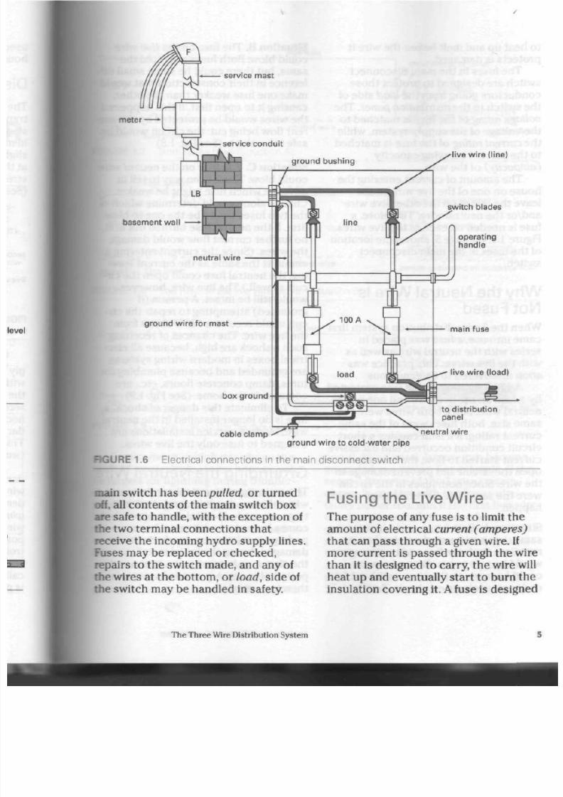
switch. As Figure 1.6 shows, the supply
lines are conne cted
at
the top
of
the
switch, which is stand ard practice . The
upper portion
of
the sw itch is called
the
line side. Most manufacturers have the
word line printed somewhere near
the
line termin als.
Should an electrical em ergency arise,
turning this switch
off
will disco nne ct
the pow er supply to all parts of the
hou se. Power may
be
restored by turn
ing th e main switch on again. Once th e
The Three Wire Distribution System

8/19/2019 Applications Electrical
http://slidepdf.com/reader/full/applications-electrical 9/447
high tension pr imary l ines
(2400 V)
transformer and
neutra l grounded
N O T E :
To save cost of materials and wire,
the earth (ground) is used as a return
path for the primary circuit.
FIGURE 1.4 T ypical 3 wir e distribution system
distr ibut ion t ransformer
outdoor meter
service conduits -»
service mast
outdoor meter
\
service conduit
grade le
t
1 m m i n i m u m
i
hydro supply l ines (120 V/240 V) •
high tension primary lines (2400 V)
FIGURE 1.5
Underground distribution system
Applications of Electrical Construction
8/19/2019 Applications Electrical
http://slidepdf.com/reader/full/applications-electrical 10/447
meter
service mast
service conduit
basement wa
live wire (line)
switch blades
operating
handle
ground wire
for
mast
box ground
cable clamp
neutral wire
g ro u n d w i re to cold-wa ter pipe
RGURE 1.6 Electrical connections in the main disconnect switch
main
switch h as been
pulled, or
turned
off. all co nt en ts
of
the m ain switch box
are
safe to hand le, with the e xcep tion of
the two terminal connection s th at
receive the incoming hydro supply lines.
Fuses may
be
replaced
or
checked,
repairs to the sw itch made,
and
any of
the wires
at
the bottom,
or load,
side of
the switch may be handled
in
safety.
Fusing the L ive W ire
The purpose
of
any fuse is
to
limit th e
amount
of
electrical
current (amperes)
that can pass through
a
given w ire.
If
more current
is
pass ed through the wire
than
it
is designed
to
carry, the wire wil
heat up and eventually start
to
burn
the
insulation covering it.
A
fuse is design ed
The Three Wire Distribution System

8/19/2019 Applications Electrical
http://slidepdf.com/reader/full/applications-electrical 11/447
•
to heat up and melt
before
th e w ire it
protects is damaged.
The fuses in the main d isconn ect
switch are designed to protect those
con ducto rs going from the
load
s ide of
the switch to the
distribution panel.
The
voltage rating
of the fuse is m atche d to
the v oltage of the supp ly system , while
th e current rating of the fuse is ma tched
to the curren t carrying capacity
(ampacity) of the wire.
The amount of current entering the
ho use on one of the live wires must
leave the hou se on the othe r live wire
an d/o r the neu tral wire. Therefore, a
fuse is need ed on each of the live wire s.
Figure 1.6, on page 5, show s th e location
of the fuses in the main disconnect
switch.
W hy the N eutral W ire Is
Not Fused
W hen the 3 wire distribution sy stem first
ca m e into use, a fuse was placed in
series with the ne utral wire as well as
with the live wires. This practic e w as
soon d iscovered to be dangerous.
A 120
V
lighting circuit was protected
by a fuse on th e live wire and o ne on the
neutral w ire. Since both w ires were the
sam e size, both fuses w ere of the sa m e
current rating.
If
a fault c ausing a sh or t
circuit condition occurred and excessive
cur ren t sta rte d to flow, th e fuse would
open the circuit and prevent damage to
th e wire. Since both fuses in th e circu it
we re the sam e size, several things could
happen:
Situation A.
Both
fuses could blow at the
sam e time and preven t any further cur
ren t flow. Both the live and ne utral wires
would be safe to hand le, and repairs
could b e ma de to the circuit without fear
or dan ger of electrical sh ock . (See Fig.
1.7)
Situation
B. The fuse on t he
live
wire
could blow. Both fuses are rated the
same, but there could be some small di
ference in their con struction tha t would
mak e on e fuse we aker than th e other,
causing it to open first. If this happened
the wires would b e protected by the cu
rent flow being cut: the circuit would be
safe t o work o n. (See Fig. 1.8)
Situation
C.
The fuse on th e neutral wir
could blow. Th ere is no w ay to tell in
advance which fuse might be weaker.
Chance alone would determ ine w hich o
the two fuses would be the on e to blow
first.
If
the neutral fuse burned out first
no further curren t flow would dam age
the w ires. (Since the cu rrent entering a
circuit is the sam e as the curren t leav
ing, th e neu tral fuse could open t he cir
cuit a s w ell.) The live wire, however,
would still be intact.
A
person (if
grounded) attempting to repair the cir
cuit could receive a 120 V shock from
the live wire. Th e ch anc es of receiving
such a shock a re high, beca use all elec
trical boxes in m odern wiring sy stem s
are ground ed an d bec aus e plumbing fix
ture s, damp c on crete floors, etc., are
com m on in th e hom e. (See Fig. 1.9)
To eliminate th is dang er of shock , a
fuse is no longer installed in th e neu tra
wire.
Modern service installations are
designed to fuse only the live w ires.
Grounding the Neutral Wir
The m ajority of electrical service p arts
wiring boxes , cond uits , and sim ilar fit
tings are m ade of metal. Sometimes, wi
comes in contact with metal boxes—
perha ps insulation on condu ctors w as
damaged during the initial installation o
the circuit or becam e worn over a
perio d of yea rs. A grounded system is,
therefore, needed.
Applications of Electrical Construction

8/19/2019 Applications Electrical
http://slidepdf.com/reader/full/applications-electrical 12/447
o-
fuse b lown
J
5
-
live wire
120
V
ground fuse b lown
FIGURE 1.7 Both fuses blow (S ituation A ).
neutral wire
short circuit at lamp
no shock
person grounded on concrete f loor
O-
fuse b lown
J>-
l ive wire
120 V
0
^ - - - c T \ j > -
grou nd fuse intact
neutral wire
HGUR E 1.8 The fuse on the live wire blow s (S ituation B).
short circuit at lamp
no shock
person grounded on concrete f loo
0 -
fuse intact
live wire
120 V
/~\
neutral wire
O - f -
o o
ground fuse b lown
RGURE 1.9 The fuse on the neutral wire blows (Situation C).
.short circuit at lamp
120 V s hock
person grounded on concrete f loo
Service masts,
which rise above the
roofs of many single-storey h ou ses , can
be targets for lightning during
thunder
storm s. To prevent thes e metal co ndu its
from attra cting lightning, they and thei r
boxes are grounded . Steel rods are
driven into the earth or wire fastened
onto cold-water pipes where they enter
houses.
If on e of the tw o live wires in th e 3
-*ire
system com es in con tact with a
grounded service box, many dangerous
possibilities arise. Anyone can becom e
grou nde d in a hou se . For exam ple, if th e
seco nd live wire of the 3 wire system
comes in contact with the frame of a
faulty power tool and if the first live wire
touc hes t he metallic service box, a
grounded pers on could receive a 240
V
shock—strong
enou gh t o kill.
A
person
trying to fix a light over th e k itchen sink
could receive a 240
V
shock by touching
th e sink and th e secon d live wire in th e
fixture. Cleaning a laundry room fixture
The Three Wire Distribution System

8/19/2019 Applications Electrical
http://slidepdf.com/reader/full/applications-electrical 13/447
fuse
2400
V
l ive wire
t
240 V
neutral_wire_
t
120 V
J
person rece
240 V sh
accidenta l groun d
on
l ive wire
FIGURE 1.10 Accidental grounding of the live wire creates a 240 V shock hazard.
fuse
2400
V
l ive wire
t
240 V
_neutral_wire_
- ^ -
intentional
ground 120
V
I
fuse
person rece
120 V sh
person rece
120
V
sh
FIGURE 1.11 Grounding the neutral wire limits the shock hazard to 120 V.
with
a
dam p cloth while standing on the
basement floor might also result in
a
240 V shock . (See Fig. 1.10)
In mod ern s ervice installations,
the
main switch box is grounded and
a
termi
nal block is placed in th e lower portion
of the sw itch, wh ere the neutral w ire
could also be intentionally grounded .
With the neutral wire groun ded,
the
maximum shock
a
perso n can receive
from any o ne live wire is
120
V. T his
means that a grounded person working
with power tools, repairing equipm ent,
or cleaning fixtures can receive no more
than the voltage between the neutral
and
a
live wire, th at is, 720
V
Under cer
tain co nditio ns, this voltage can kill, but
th e da nge r is greatly redu ced . (See Fig.
1.11)
If
one of the live wires acc identally
touches a metal box or fitting with the
neutral wire ground ed,
a
short
circuit
resu lts. The fuse on th e live wire blow
and pr otec ts the circuit. The neutral
wire is safe to han dle even wh en
a
per
son is grounde d, since th ere is no volt
age difference b etwe en
it
and ground.
Unbalanced System
When
a
distribution panel
is
installed
a hous e, some attem pt is usually m ade
to distribute th e load evenly
on
each o
the live wires supplying the panel.
It
is
rare, however, for a dwelling to hav e t
same number of lights or devices turn
on for the load
to be
balanced
on
each
side of th e panel. Th e
neutral
wire in t
system is important here, because it
returns the unbalanced amount of cur
rent to the transformer.
If the neutral wire is broken or
disconnected in any way, th ere is dan
to the electrical equipm ent
in
the circ
Applications
of
Electrical Construction

8/19/2019 Applications Electrical
http://slidepdf.com/reader/full/applications-electrical 14/447
Assuming that eac h individual load
device
draws the same current, the side
x
the system with the g reatest nu m ber
* devices turned on will have the
neatest number of parallel circuit paths.
ma parallel circuit, the m ore paths the re
are.
the lower the total res istance of th e
circuit. The difference in electrical
lesistance between the two sides of the
panel is determined by the nu mb er of
devices operating on each side .
If the n eutral w ire is d isco nne cted ,
there will no longer be a
120 V
circu it.
Th e two sides will now be
in
series with
each o ther and have an applied voltage
•& 240
V Since voltage is divided in a
series circuit, the side of th e panel w ith
fewer devices turned on (and, therefore,
higher resis tan ce) will receive a vo ltage
auch
higher than norm al. The o ther
side of the panel, with its lower resist-
• c e ,
will receive the bala nce of th e
240
V.
Light bulbs will glow muc h m ore
brightly with the increased voltage, and
sensitive equipment, such as stereos
and television sets, may be seriously
damaged. When connecting service con
duc tors, therefore, the
neutral
wire must
be disconnec ted last and reconnected
mrst,
when pow er is to be restored .
The danger of an unbalance d condi
tion is an oth er reaso n for never fusing
the neutral wire.
A
blown fuse on the
neutra l wire will result in an u nbala nced
voltage situation.
As current passe s through a circuit,
each lamp forms part of the circuit and
offers som e resistance to the current
flow. (See Fig. 1.12) Three factors are
involved in curre nt flow: line
voltage,
amperage, and resistance. The value of
each factor is determined according to
Ohm's
Law:
Current =
Voltage
Resistance
In term s of un its, th e Law can be
expressed as follows:
Amperes =
Volts
Ohms
As a mathe ma tical formula, it is state d in
this way:
" I
To mak e calculation easier, each
lamp shown in Figure 1.12 is the same
size,
receives
120
V, and draw s
1 A
of
curren t. The resistanc e of o ne lamp is
found by using Ohm 's Law:
" * \ *
4 A
I
m •
1 2 0 V
group 1
X
\ -
2 A
120 V
-o o o 9
< <
group 2
2 A
RGURE 1.12 Each lamp is the same size (amperage). T he current flows as show n by the
The T hree Wire Distribution System

8/19/2019 Applications Electrical
http://slidepdf.com/reader/full/applications-electrical 15/447
Transposed, this equals
since
R
rep resen ts Resistance, which is
measured in Ohms.
R
(Ohms) =
E
(Volts)
/ (Amps)
Therefore, the resistance of one lamp
.
120 V
equals
I Pi.
That
is,/?
equals 12 0ii .
The resistance of one lamp is 120 ii.
The total resistance of all lamps of
the same size in a parallel
circuit
is equal
to the res istanc e of one lamp divided by
the number of lamps in the circuit.
Re sistanc e of the lam ps in Group 1:
120
i i
R
= = 30 i i
4 (lamps)
Res istance of the lam ps in Group 2:
120 i i
R = =
60
i i
2 (lamps)
When th e neutral wire is broken, the
lamps in Groups 1 and 2 are in series
with e ach other. (See Fig. 1.13) T he total
resistance tor the whole circuit is now
the sum of the resistances in Groups 1
and 2 wh ich is 30
ii
+
60
i i =
90
ii.
Since the neutral wire is broken, the
line voltage is now 240
V,
and the total
current in the circuit is
.
E
240 V
9
„ .
/ =
J?
=
"90ii-
= 2
-
6 7 A
Th e voltage in a series circuit is
divided between t he groups of lamps,
according to Ohm's Law:
'
= 1
Transposed, this equals
E
(V) = / (A) x
R
(i i)
The voltag e of Group
1
is
E =
2.67
A x
30
i i
= 80.1V
This low voltage will cau se th e lam ps in
Group 1 to glow dimly.
The v oltage of Group 2 is
E
= 2.67 A x 60 ii
= 160.2
V
side 1
240
V
o —
side 2
\r
2.67
A
neutral broken
S\j,
2.67 A
group
30 Q
80.1 V
\ *S s / \ i / group
- 6on
' T f
s /
Tf
N
160.2
V
FIGURE 1.13 Each lamp is the same rating (wattage). T he current flow is altered wh en the
neutral wire is
broken.
10
Applications of Electrical Construction
8/19/2019 Applications Electrical
http://slidepdf.com/reader/full/applications-electrical 16/447
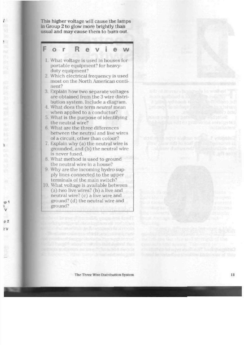
This higher voltage will cause th e la m ps
in G roup 2 to glow more brightly than
usual and may cause them to burn out.
F o r R e v
i e w
1. What voltage is used in houses for
portable equipment? for heavy-
duty equipment?
2. Which electrical frequency is used
most on the North American conti
nent?
3.
Kxplain how two sepa rate voltages
are obtain ed from the 3 wire distri
bution system. Include a diagram.
4.
What does the term
neutral
mean
when applied to a conductor?
5.
What is the purpose of identifying
the neutral wire?
6. What are the th ree differences
between the neutral and live wires
of a circuit, other than colour?
7. Explain why (a) the neutral wire is
grounded, and (b ) the neutral wire
is never fused.
8. What method is used to ground
the neutral wire in a house?
9. Why are the incoming hydro sup
ply lines connected to the upper
terminals of the main switch?
10.
What voltage is available b etwe en
(a) two live wires? (b) a live and
neutral wire? (c) a live wire an d
ground? (d) the neutral wire and
ground?
The T hree Wire Distribution System

8/19/2019 Applications Electrical
http://slidepdf.com/reader/full/applications-electrical 17/447
• ^
T
he flow of electrical cu rren t in th e
vario us circu its of a building m ust
be co ntrolled. This is don e by using a
variety of switches capable of opening
and closing the circu its.
Switches are divided into two main
catego ries according to the m ethod of
installation:
Category 1.
The
surface
type of switch
is m ou nted on th e face of th e wall, with
the entire body of the switch visible.
(See
Fig. 2.1) '
o
GO
1
C O
FIGURE 2.1 S urface-mounted switch
Category 2.
The
flush
type of switch
unit is mounted within an electrical box.
Light ing-
Control
Switches
FIGURE 2.2 Flush-mounted switch
This box is recesse d in to the wall, so
that only the operating h andle of th e
switch is visible. This typ e of switch
looks neater and is used more exten
sively. (See Fig. 2.2)
Operating Mechanisms
Th ere ar e m any different typ es of
switches to con trol a wide variety
of
electrical devices. Just as there are
many switches, there are also many dif
ferent type s of operating mec hanism s to
suit individual circuit n ee ds . Figure 2.3
shows some of the m ore common opera
ting mechanisms.
12
Applications of Electrical C onstruction
8/19/2019 Applications Electrical
http://slidepdf.com/reader/full/applications-electrical 18/447
wal l -
mounted
toggle
rocker
push
button
key
operated
panel-
mo u n te d
toggle
pull chain
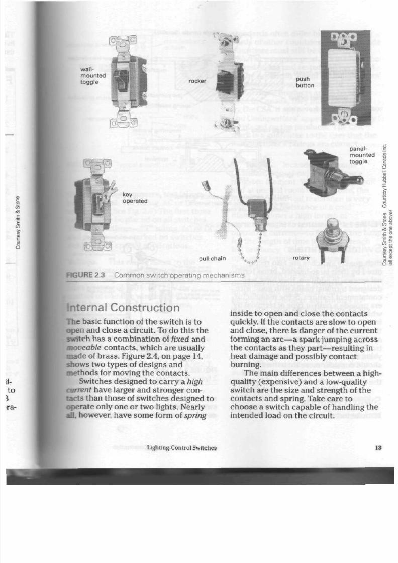
R G U R E
2 .3
C o m m o n s w i t c h o p e r a ti n g m e c h a n i s m s
rotary
Internal Construction
The basic function
of
th e sw itch is
to
open and close a circuit. To do this the
switch ha s a combination of fixed and
mtoveable co ntac ts, which are usually
made
of
bra ss. Figure 2.4,
on
pag e 14,
shows two types
of
designs and
methods for moving the contac ts.
Switches designed
to
carry
a
high
current have larger and stronger con
tacts than those of switch es designed to
ope rate only one or two lights. N early
all,
however, h ave s om e form
of
spring
inside to open and close the contac ts
quickly. If the contacts are slow
to
open
and close, there
is
danger
of
the current
forming an arc—a spark jumping ac ross
the con tacts as they
part—resulting
in
heat damage and possibly contact
burning.
The main differences between a high
quality (expensive) and a low-quality
switch are the size and strength
of
the
con tacts and spring. Take care to
choose a switch capable of handling the
intended load on the circuit.
Lighting-Control Switches
1

8/19/2019 Applications Electrical
http://slidepdf.com/reader/full/applications-electrical 19/447
toggle handle (Bakelite)
terminal screw (brass)
blade contact (brass)
body
or
case (Bakelite
or
porcelain
plaster ear (removable
mounting bracket (steel)
jaw contact (brass)
spring assembly (steel)
toggle handle mo unt in g bracket
4
spr ing
- contact poin ts
rD <-
terminal
N O T E : A
semisilent-type
switch does not
us e a b lade and jaw contact system.
Contact points
are
used.
FIGURE
2.4
Internal construction
of
a
single-pole switch
Switch Terminals
High-quality switch es a re also recog
nized by their large-headed, brass termi
nal screw s.
In
addition, they have well-
designed terminal bases with good wire
containment features. Some manufactur
ers provide a
push-in
type
of
terminal
by
which the terminal screw ho lds the wire
in a vise-like grip. (See Fig. 2.5) S witch es
that m ake sole use of the push-in
method of holding the wire may give
trouble
at
their terminal conn ections
in
years to come, thoug h. The installer
should consider more than the ease with
which
the
switches
can be
installed
in
the circuit.
Switch Ratings
Manufacturers usually place electrical
CAPTIVE MOUNTING
SCREWS FIT ALL BOXES
ON AC SWITCHES 1ME
wine
GAGE SHOWS
MOW EAR TO STRIP WIRES
S C R E W
RETAINING
O V A L H O L E RERMfrs
ADJUSTMENT IN CROOKED
Box
TERMINAL SCREWS FOR
SIDE
AND
OR
BACK
WttING
MOLDED UREA OR
PORCELAIN BODV
O N AC SWITCHES. COLOR
OF FRONT INDICATES
AMPERAGE
FIGURE
2.5
Rear vie w
of
a switch showing
2 types
of
terminal connections
ratings on th e m ounting bracket of the
switch. There are six possible ratings to
assist
a
person
in
matching the switch
t
u
Applications
of
Electrical Construction
8/19/2019 Applications Electrical
http://slidepdf.com/reader/full/applications-electrical 20/447
nting bracket
power rating
iting
marks
amperes
manufacturer's
emblem
Canadian
Standards
Association
approval
alternating
current
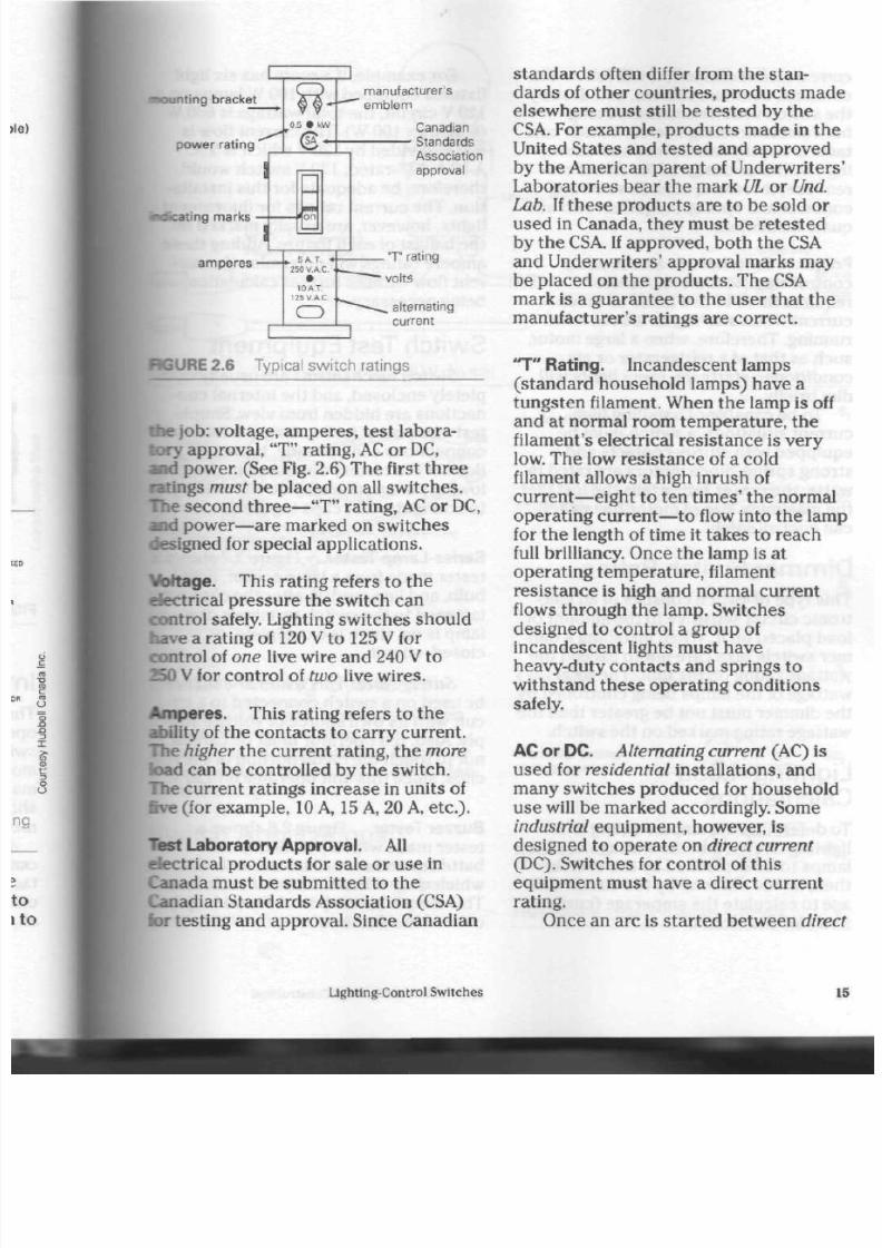
RGURE 2.6 Typical switch ratings
die job: voltage, amp eres, test labora
tory appro val, "T" rating, AC or DC,
and pow er. (See Fig. 2.6) The first th re e
ratings must be placed on all sw itche s,
rhe second three— "T" rating, AC or DC,
and power—are marked on switches
designed for special applications.
Voltage. This rating refers to th e
electrical press ure the switch can
control safely. Lighting switches should
have a rating of 120 V to 125 V for
control of
one
live wire and 240 V to
250 V for con trol of
two
live wires.
Am peres . This rating refers to the
ability of the contacts to carry current.
The
higher
the cu rrent rating, the
more
load can be controlled by the sw itch.
The
curre nt ratings in crea se in units of
live
(for
exam ple, 10 A,
15
A,
20 A, etc.).
Test Laboratory Approval.
All
electrical products for sale or use in
Canada must be submitted to the
Canadian Standards Association (CSA)
for testing and approval. Since Canadian
standards often differ from the stan
dards
of
other countries, products mad
elsewhere m ust still be tested by the
CSA. For example, pro du cts m ade in
the
United States and tested and approved
by the American paren t
of
U nderwriters
Laboratories bear the mark
UL or Und
Lab.
If the se pro du cts a re
to
be sold
or
used
in
Canada, they must be retested
by the
CSA.
If appro ved , bo th the CSA
and Underwriters' approval marks may
be placed
on
the pro du cts. The CSA
mark is
a
guarantee to the user that
the
manufacturer's ratings are correct.
"T"
Rating. Incandesce nt lamps
(standard househo ld lamps) have
a
tungsten filament. When the lamp is off
an d
at
normal room tempe rature,
the
filament's electrical resistance is very
low. The low resis tanc e
of a
cold
filament allows
a
high inru sh of
current—eight to
ten tim es' the norm al
operating
current—to
flow into the lam
for th e length of time it takes to reach
full brilliancy. Once th e lam p is at
operating temperature, filament
resistance is high and normal current
flows through the lamp. Switches
designed to control a group of
incandescent lights must have
heavy-duty contacts and springs to
withstand these operating conditions
safely.
AC or DC.
Alternating current
(AC) is
used for
residential
installations, and
many switches produced for household
us e will be marke d acco rdingly. Som e
industrial
equipment, however, is
designed to operate on
direct current
(DC). Sw itches for control of this
equipment must have a direct c urrent
rating.
Once an arc
is
started between
direc
Lighting-Control Switches

8/19/2019 Applications Electrical
http://slidepdf.com/reader/full/applications-electrical 21/447
current switch contacts,
it will follow th e
contacts, continue to burn, and destroy
the switch within seconds. (Arcing
between alternating current switch con
tacts is usually less severe and damag
ing.) Switches d esigned for direct cur
rent use, therefore, must hav e strong
contacts and springs, together with ade
qua te insulation.
Power. Switches are also used to
control electric motors. A motor
requires thre e to five times as mu ch
curren t when start ing as i t doe s when
running. Therefore, when a large motor,
suc h as tha t of a refrigerator or air
conditioner, starts up, room lights will
dim briefly.
To be capab le of handling high-
curre nt situations, a switch must b e
equipped with sturdy contacts and a
strong spring. Since mo tors a re rated in
watts,
the power rating tells the installer
the maximum size of motor the switch
can control safely.
Dimmer Switch Rat ing
This ty pe of switch con sists of an elec
tronic circuit sensitive to the amount of
load placed on it. When installing a dim
mer switch, take care not to exceed t he
wattage rating on the unit. The total
wattage of the lamps being controlled by
the dimmer must not be greater than the
wa ttage rating marked on the sw itch.
L i g h t i n g - L o a d
Calculations
To determ ine th e am pere rating of a
lighting circuit, add th e wa ttage of all th e
lamps to be controlled by the switch;
then, divide the total by the circuit volt
age to calculate the amp erage (current
flow) for the circuit.
For example, if a room has six light
fixtures equipped with 100 W lamps on
120
V
circuit, the to tal wa ttage is 600
W
(6 lights x 100
W ).
The curre nt flow is
600 W divided by 120 V which is 5 A.
A
10 A,
"T"-ra ted, 120
V
switch would,
therefore, be adequate for this installa
tion. The cu rren t ratings for fluorescent
lights,
however, are usually marked on
th e ballast of each fixture. Adding th es e
am pere ratings will determ ine the cur
rent flow without further calculation
being necessary.
S witch Test E quipment
Switch m echanism s are usually com
pletely enclosed, and the internal con
nections are hidden from view. Simple
test equipment for locating the internal
connections can be made, however.
Both of the testers described in the fol
lowing paragra phs may be checked by
touching th e test clips together.
Series-Lam p Tester. Figure 2.7 sho w s
tester made from a lamp socket, light
bulb, and line cord. If, after the clips are
fastened to the switch terminals, the
lamp is on, there is a com plete, or
closed, circuit.
Safety Note:
This tester should not
be used on a switch con nected to a cir
cuit with its own s our ce of voltage su p
ply. Also, th e o pe rato r m ust be careful
not to touch t he me tal portion of the tes
clips, since this unit op er ate s on 120 V.
Buzzer Tester. Figure 2.8 show s a
tes ter ma de with a pair of dry cell
batteries and a small buzzer or bell,
which rings when the circuit is closed.
This simple unit is portab le and may be
carried in a tool box.
16
Applications of Electrical Construction

8/19/2019 Applications Electrical
http://slidepdf.com/reader/full/applications-electrical 22/447
N O T E :
Spl ice wires.
Insulate wi th tape.
1
lampholder
l ine cord
plug cap
F I G U R E 2 . 7 S e r i e s - l a m p t e s t e r (120 V d e v i c e )
binding jumper
posts
y
f lexible cord
f r ic t ion tape
R G U R E 2 . 8
B u z z e r t e s t e r ( b a t t e r y -
p o w e r e d )
s ingle-pole switch
double-pole switch
3 way switch
o-
» o-
<yTo
^t
Switch Wir ing Symbols
A
system of electrical sym bols is often
used to represent various types of
switche s on wiring diagram s. Figure 2.9
shows symbols comm only used on elec
trical draw ings.
Switch Appl icat ions
Switches are available in a variety of
types for a variety of u ses . Single-pole
and double-pole switche s are used to
control lights or equipment from one
4 wa y s wi t c h
electrolier (tr i l i te)
(2 circuit switch)
electrolier
(3 circuit switch)
>£
F I G U R E 2 . 9 S w i t c h w i r i n g s y m b o l s
S E
S E
Lighting-Control Switches
8/19/2019 Applications Electrical
http://slidepdf.com/reader/full/applications-electrical 23/447
location. Three-way switches are used to
con trol lights in area s such a s room s
with two e ntran ces, hallways, or stair
ways wh ere it is conv enient to hav e con
trol from either of two locations. Four-
way switches are used where multiple-
switch control is needed, for example, in
large houses, apartment buildings, or
office buildings that have large rooms
with three or more entrances or stair
ways rising thre e or more stor ey s.
Single-Pole Sw itch. As th e most
commonly used switch for residential
and commercial lighting circuits, this
switch is also appropriate for fractional
kilowatt motors, portable appliances,
portable tools, etc.
The single-pole unit is designed to
control a 120 V circuit (on e live wire)
from one location. The two terminal
screws and the indicating marks (on and
off) on th e opera ting hand le make it
easy to recognize. (Some man ufacturers
use a small dot on the operating handle
to indicate the on position.) This switch
is available in a varie ty of styles and
operating mechanisms, with current rat
ings to suit any installation for which it
was designed.
When installing a single-pole switch
with a toggle or rocker mec hanism,
standard procedu re is to moun t the
switch with the operating h andle in the
up po sition (when the switch is turned
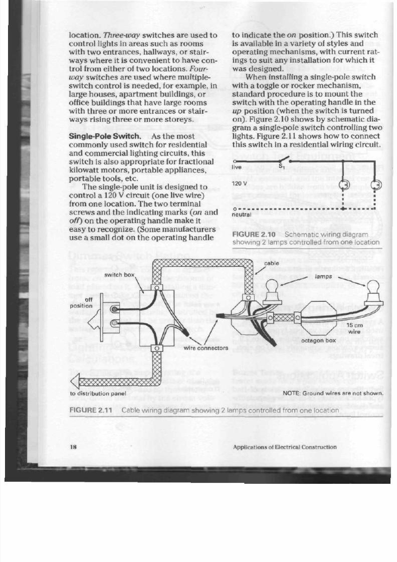
on). Figure 2.10 show s by sche m atic dia
gram a single-pole switch controlling tw
lights. Figure
2.11
shows how to c onnec
this sw itch in a residential w iring circui
live
120
V
- ^ .
o
.
neutral
FIGURE 2.10 S chematic wiring diagram
showing 2 lamps controlled from one location
switch box
off
posit ion
15 cm
wir e
octagon box
to dis t r ibut ion panel N O TE : Groun d wires are not sho w
FIGURE 2.11 C able wiring diagram showing 2 lamps controlled from one location
18
Applications of Electrical Construction

8/19/2019 Applications Electrical
http://slidepdf.com/reader/full/applications-electrical 24/447
o
live
Si
120 V
lamp of f
safe:
no shock
person grounded
o -
-
neutral
c-
live
120
V
lamp off
o
-
»
i
neutral
• ^
danger: 120 V shoc
person grounded
RGURE 2.12 The danger in conn ecting a sw itch in the neutral wire
Remember that only the live wire is
connected to the switch. (See Chapter 1)
Figure 2.12 shows the danger of using
the ne utral wire, or groun ded , identified
conductor, to contro l the circuit. In
either case , th e light may be turn ed off,
but the live wire is still dan gero us at th e
light fixture.
Double-Pole S witch . This switch is
available in a variety of cu rren t ratings ,
but m ost often in the heavy-d uty ran ge,
ft is meant to control such energy u sers
as electric heate rs, air conditioners, and
some motors operating on 240
V.
Two
live wires and a switch cap able of
opening both live conductors of the
circuit simultaneously are required. The
double-pole switch, much like a pair of
single-pole switche s in the sam e case, or
body, is easily recognized by th e four
terminal screw s and t he indicating
marks on the operating handle.
When installing a d ouble-pole
switch, take care to co nnect the circuit
conductors to the proper terminals. This
preven ts short-circuit damage to the
switch contacts. Figure 2.13 shows by
schem atic diagram a double-pole switch
controlling an electric hea ter.
Figure 2.14 show s an im prope r con
nection, which will damage the switch
badly the instant it is turned on.
heater off
W - i
on posi t ion
FIGURE 2.13 S chematic wiring diagram of a
double-pole switch
Lighting-Control Switches
1

8/19/2019 Applications Electrical
http://slidepdf.com/reader/full/applications-electrical 25/447
live
c—
240
V
live
heater
• £ .
A M A - i
short c i rcui t when switch
contacts close
FIGURE 2.1 4 C ontact dama ge results if a
double-pole
switch is connected improperly.
live
c —
240
V
o-
live
person receives 120 V shock
heater
this wire not control led by switc
FIGURE 2. 16
N ever use a single-pole
sw itch on a 240 V circuit.
to panel
red wire
box
gr ound
screws
s wi t c h
box
cable
connector
NOTE: Both wires in th is c ircui t are al ive and should be
coloured accordingly. The modern cable containing
one red and one black w ire sho uld be used.
FIGURE 2.15
C able wiring diagram of a
double-pole switch
Figure 2.15 sho ws how to con nec t
this sw itch in a residential wiring circuit.
Safety Note:
Rem ember tha t a sin
gle-pole switch must not be used on a
240
V
circuit. Figure 2.16 shows the dan
ger of such a connection.
Three-Way Sw itch. These switches
are u sed in pairs , usually on
120 V
circuits. They c ontrol on e live wire in
order to provide indepen dent control of
a light or group of lights from either
of
two locations.
A
3 way switch is easily
recognized by its three term inals, one of
which is marked as a line terminal, and
by its lack of indicating ma rks. (The
word line may be printed be side the ter
minal, or the term inal may be coloured
for easy recognition.)
The internal design of th e 3 way
switch allows current to flow through
th e switch in either of its two po sition s.
For this reason, the switch h as no on/o
ma rks on the operating ha ndle. The cir
cuit is controlled by using two sw itches
as a tea m . Figure
2.17
shows the interna
switch positions and also how on e term
nal—the
common, or
line, terminal—is
used for both switch positions. Figure
2.18 shows b y schem atic diagram 3 way
switch control of one light.
This switch is available in a va riety
of styles and op erating m echanism s,
with current ratings to match the load
being con trolled. Figure 2.19 sho w s ho w
to connect this switch in a residential
wiring circuit. The two con duc tors run
ning between the switches are often
called travellers, or messenger w ires. If
the need a rises, this switch may also be
posit ion 1
posi t ion 2
0
S
0
©
• — ©
0
t
—
l ine termin al
FIGURE 2. 17 Internal connections of the 3
way switch
20
App lications of Electrical Co nstruction

8/19/2019 Applications Electrical
http://slidepdf.com/reader/full/applications-electrical 26/447
n
—v
Z
ravellers
•23
V
light on J
-
= Jtral
RGURE2.18 S chematic wiring diagram
.ving 1 light controlled from tw o locations
live
o n
line
s t c ^
=>3 O .
Do not use
this termi nal.
120 V
lamp on
,
o - - - -
neutral
FIGURE 2.20 S chematic wiring diagram
showing how a 3 way sw itch can be used
safely in place of a single-pole sw itch
line terminal
N — ^ black
/
lamp
to distribution
panel
RGURE 2.19 C able wiring diagram of 3 way switch control
used safely as a
single-pole
sw itch. Fig
ure 2.20 shows by schem atic diagram
such a circuit.
Four-Way Sw itch. Multiple-switch con
trol in large rooms or buildings is
achieved by using 4 way switches in
com bination w ith a pair of 3 way
switches in 120
V
c ircuits. This com bi
nation is particularly useful in suc h
areas as large room s with thre e or m ore
entrances and stairwells in buildings
of three o r m ore sto rey s. Control of
the light from a ny of the sw itch pos itions
may be obtained by operating any one
of the switches in th e grou p.
The 4 way switch is a non-indicating
switch, bec aus e the lights can b e con
trolled by any one switch in th e circuit.
It can be recogn ized by its four term inals
and lack of indicating marks on the oper
ating handle. Without pro per test equip
men t, th e only way to tell th e difference
between the 4 way and the double-pole
switch is to rem emb er that th e 4 way
has no indicating marks, while the
double-pole switch d oes.
The 4 way switch is available in a
variety of styles and operating mecha
nism s. It is thus a ble to suit any a pplica
tion. However, becaus e the internal
mechanism is more complicated and
the re is less consu me r de man d for it, th
4 way switch m ay be more expensive
than other types.
Figure
2.21
show s th e internal switc
pos itions , and Figure 2.22 sho ws by
schematic diagram control of a light
from th re e loc ation s. Figure 2.23 sho w s
control from five locations, and Figure
2.24 show s how to con nect this switch i
a wiring circuit.
Ughtlng-Control Switches
2

8/19/2019 Applications Electrical
http://slidepdf.com/reader/full/applications-electrical 27/447
posit ion 1 posi t ion 2
0
X
0
FIGURE
2.21
Internal connections of the 4
way switch
c
'
J (-travellers-,
\ > -
live
o—i^^—o
o
1 o
ne
120 V
l ight on
o
neutral
FIGURE 2.22 S chematic wiring diagram
showing
1
light controlled from three loca
tions
.travellers
live O——
<S
„ t^—
l ive
120 V
l igh t on ,
o
- - - -
neutral
FIGURE 2.23 S chematic wiring diagram
showing 1 light controlled from five locations
Electrolier Switches
Two-Circuit Electrolier. T he
2
circuit
electrolier is mo re comm only known as
the trilite switch . Used with th e d ual
filament lamp , it prov ides thre e levels of
light (low, me dium , and h igh) for m any
table lam ps, floor lam ps, pole lamp s,
and hanging, or swag, lam ps. (See Fig.
2.25) Th e switch u nit and bulb in
combination give this circuit its
versatility.
The trilite switch h as thre e termi
nals,
o r leads, and is almost always a
rotary switch. It usually ha s no indicat
ing ma rks, since the installer may use
either of the two line term inals, depe nd
ing on the choice of seq ue nc e. Trilite
switches are used mainly for
120 V
lighting un its.
Figures 2.26 an d 2.27 sho w th e four
positions of the trilite switch. One termi
nal, called th e common, or line, terminal,
is use d in all th re e of th e on positions.
To tu rn th e bu lb off, th e bla de s of th e
switch are simply moved away from the
line term inal.
A
lam p with a switch a s
show n in Figure 2.26 ope rate s in a high,
medium , and low sequ enc e. If the switch
is con nec ted w ith the line termina l as
show n in Figure 2.27, howe ver, the lamp
will ope rat e in a low, me dium , and high
sequence.
to dis t r ibut ion
panel
FIGURE 2.24 C able wiring diagram showing 3 way and 4 way sw itch control
22 Applications of Electrical Co nstruction

8/19/2019 Applications Electrical
http://slidepdf.com/reader/full/applications-electrical 28/447
switch
switch
table lamp
swag lamp
floorlamp
rotary tri l ite switch
V
switch
O
pole lamp
R G U R E S 2 . 2 5 A A N D B T y p i c a l 2 a n d 3 c i r c u i t e l e c t r o l ie r s w i t c h a p p l i c a t i o n s
terminal
h igh medium low
R G U R E 2 . 2 6 T r i li te s w i t c h p o s i t i o n s f o r h i g h t o l o w s e q u e n c e
Lighting-Control Switches

8/19/2019 Applications Electrical
http://slidepdf.com/reader/full/applications-electrical 29/447
of f low m e dium
FIGURE 2.27 T ril ite sw itch positions for low to high sequence
high
Trilite bulbs are available in three
sizes, or wattage ranges. The largest has
a mogul base equipped with 100 W and
200 W filaments. Both filaments opera
ting together provide 300 W of light in
the high position. The other two bulb
sizes use a
medium
base and are availa
ble in 50
W-100 W-150
W and 40
W-60 W-
100 W combinations. These units are
popular for smaller light fixtures.
Figure 2.28 shows the sw itch and
socket assembly wired as a working unit.
Some table and floor lamps are manufac
tured with a switch built into the socket
assembly. The only connections
required are for the live and neutral
wires in the lamp's cord. The switch may
be purchased as a separa te unit for con
nection to two independent light sock
ets,
as shown in Figure 2.29. This type o
connection may be installed in fixtures
using two standard light bulbs, rather
than the trilite bulb.
200 W f i lamen
100 W
f i lame
to centre contac
to r ing conta
ring
conta
centre conta
silver scre
120 V
centre contact scre
FIGURE 2.28 S chematic wiring diagram showing a 2 circuit electrolier switch
24
Applications of Electrical Con struction

8/19/2019 Applications Electrical
http://slidepdf.com/reader/full/applications-electrical 30/447
Three-Circuit Electrolier.
There are
two typ es of 3 circuit electroliers. The
alternate typ e (See Fig. 2.30) puts on e
bulb on at a time and may be use d for
pole lamp s or other decorative units.
The consecutive type (See Fig. 2.31) is
often fitted into po le or swag l am ps. All
three lamps may be on at the sam e time.
Dimmer Switches
Lighting no t only illumina tes, it can cre
ate m ood s, as well. For exam ple, dim
ming lights in a dining area can cre ate a
more intimate atm osph ere. Two types of
dimmer switches, the high-low and the
infinite, are commonly used in hom es
and function on electronic circuitry.
Their operating methods are described
below. Othe r dimm ers functioning on
electrical resistors alone prod uce a great
deal of he at, wh ich is difficult to d issi
pate, and so are not desirable for hom e
use.
High-Low.
This two -stage , flush-
m oun ted, wall switch usually has a
toggle action. When the operating
handle is in the up position, the
neutral
FIGURE 2.30 S chematic wiring diagram
and alternate switch positions for a 3 circuit
electrolier
typical applicat ion
FIGURE 2.29 S chematic wiring diagram
and typical application show ing a 2 circuit
electrolier switch using 2 standard light bulbs
o—
l ine terminal
120 V
o-
consecut ive switch
posit ions
6h
49-
all l ights on
—©-:
neutral
FIGURE 2.31 S chematic wiring diagram an
conse cutive sw itch positions for a 3 circuit
electrolier
Lighting-Control Sw itches
2

8/19/2019 Applications Electrical
http://slidepdf.com/reader/full/applications-electrical 31/447
stan da rd light bulb in th e fixture glows
at full brilliancy. When the operating
handle is placed in the down position,
the bulb glows at the lower level of light.
The light is turned off by moving the
handle of the switch to a centre position.
(See Fig. 2.32)
This switch is wired in a way sim ilar
to any single-pole switch. Take care to
install a switch of sufficient wattage rat
ing to ha ndle the lighting load of th e
circuit.
Infinite Dimmer Control.
This unit
mo unts in a standa rd electrical switch
box and can replace any standard
flush-mounted switch. The majority are
wall-mounted; however, units built into
light sockets for table lamp and floor
lamp applications are available. Both
single-pole and 3 way units are m ade.
The standard light bulbs used are turn ed
on or off by press ing th e con trol kn ob.
(See F igs. 2.33 and 2.34) Any level of light
from off to full brilliancy can be obtained
by rotating the control knob .
The dimmer switch is usually
equipped with leads for connection to
the electrical circuit.
case
/
terminal screw
FIGURE 2.32 High-low dimm er switch
high
Safety Note:
Take care to en sure
that th e total wattage of th e circuit load
does not exceed that marked on the
switch.
FIGURE 2.33 Infinite dimm er sw itch
FIGURE 2.34 A heavy-duty dimmer switch
equipped with an aluminum heat-sink for
proper dissipation of heat (right) compared to
a standard 600 W dimmer switch. The heavy-
duty dimmer switch can be used on lighting
circuits
up
to
1000W.
26
Applications of Electrical Construction

8/19/2019 Applications Electrical
http://slidepdf.com/reader/full/applications-electrical 32/447
F o r R e v
i e w
1.
What is the pu rpo se of a switch in
a circuit?
2.
List and describe the two main
types of switches, according to
method of installation.
3. List seven operating mechanisms
used in lighting switch es.
4. List the p art s of a switch, a nd
state the purpose of each.
5.
Define
arcing,
and describe its
effect on a switch.
6. List the six electrical ratings that
may be marked on sw itches.
7. Why do manufacturers mark elec
trical ratings on switches?
8. Explain the function of the Cana
dian Standards Association and
the American parent Underwrit
ers '
Laboratories.
9. An oil bu rne r ha s a 560 W motor
ope rating on 240 V. It it d raw s
6.9 A, what ty pe of switch is
needed to control the motor?
Which electrical ratings should
appear on the switch?
10. A room is equipped with twelve
120
V
light fixtures, each having a
100 W bulb. What type of switch is
required to control these lights?
Which electrical ratings should be
marked on the sw itch?
11. Explain how to use a series-lam p
tester to locate a switch's internal
connections.
12.
Explain why th e neu tral w ire
should never be used to control a
circuit.
13.
Explain why a single-pole switch
should nev er be used to control a
240
V
circuit.
14.
Can a double-pole switch be used
safely to con trol a
120 V
circuit?
Explain, with the aid of a diagram.
15. Explain why care m ust b e taken
when connecting a double-pole
switch to a 240
V
circuit.
16. List three places in a home where
3 way switch control would be
useful.
17.
Show by diagram a
3
way switch
being used to replac e a single-pole
switch.
18.
What is th e nam e of the two con
ductors that connect 3 way
switches to one another?
19. List the ty pes and quan tities of
switches required for stairway
lighting with co ntrol from each
storey of a six-storey building.
20. List three a pplication s of
2
circuit
electrolier (trilite) switch control
in the home.
21 . Which terminal of the electrolier
switch must be located to deter
mine lighting se quenc e?
22. Explain why you think it would be
desirable to be able to change th e
level of light in a room.
23. Explain how a trilite lamp pro
duces three levels of light.
24.
What is the advantage an infinite-
dimm er control switch has over a
trilite switch?
25. Explain why care must be taken
not to exceed the wattage rating
on a dimmer switch.
Lighting-Control Switches 2

8/19/2019 Applications Electrical
http://slidepdf.com/reader/full/applications-electrical 33/447
a
•
T
here are many types of lampholders
used for residential and commercial
lighting installations. This cha pte r cov
ers only the screw-base type.
Screw-Base Sizes
Th ere are five stand ard screw-base
sizes, each of wh ich has a partic ular
are a of us e. (See Fig. 3.1)
i f
in iature
9
intermediate
candelabra
m edium
m ogul
FIGURE 3.1 S tandard screw-base sizes
Lampholder
Mogul. As the largest of the screw-
base units, the mogul is used in reside
tial trilite lamps and in commercial are
such as parking lots, service garages,
and warehouses where larger light bul
are employed.
Mo gul-base light bu lbs rang e in siz
from 300
W
to 1500 W, which th e Cana
dian Electrical Code ha s set as th e max
mum size for incan descen t-bulb mogul
sock ets. Because 1500 W bulbs produc
a great dea l of he at as well as light,
mogul-base sock ets are usually heavy-
gauge br ass with a porcelain covering
withstand the heat .
Bulbs for the m ercury va pou r type
lamp exceed 1500 W They are also
equipped, however, with mogul bases.
Medium.
This is th e mo st comm on
residential socket size. Standard
incandescent light bulbs from 7.5 W to
300
W
are equipped with m edium base
as is the
125 V
plug fuse for the
distribution panel. Any comm ercial
lighting installation using a b ulb size of
up to 300
W
is also equippe d w ith a
medium-base soc ket .
The Canadian Electrical Code
requ ires tha t no lam p in excess of 300
be used in medium-base lam pholders,
unless th e lampholder is made of heat-
resisting material. The Code also
28
Applications of Electrical Con struction

8/19/2019 Applications Electrical
http://slidepdf.com/reader/full/applications-electrical 34/447
requires that all medium-base lamphold
ers ha ve an electrical ratin g of 660
W
and 250 V. This regulation is design ed to
protect the use r by ensuring safe opera
tion for the ra nge of bulb s available.
Intermediate. This sock et is use d for
such purposes as outdoor Christmas
tree lights, show case and aquarium
lighting, sewing-m achine lam ps, and
appliances such as electric stoves. The
intermediate socket has an electrical
rating of 75 W an d 125 V.
Candelabra. As the smallest screw-
base lampholder that may be connected
directly to a 120 V circuit, th e
cand elabra has an electrical rating of
75 W
and
125
V. Decorative lighting takes
full ad van tage of this sm all socke t. The
light bulbs use d in it are pro du ced in a
wide variety of sh ap es , often simulating
the flames of can dle s. They are ideal for
indoor Christmas tree lights and crystal
chandeliers.
Miniature.
This is the sma llest
screw-base lampho lder in the standa rd
group. It is used for dial-illuminating
panel lights in radio or television se ts.
One type of Ch ristm as tre e light string
also uses th ese so ckets in a
120 V
series
circuit. The voltage is divided am ong th e
num ber of lights in th e string, so tha t,
for example, if there are eight lights,
each light receives approximately
15 V.
This lampholder does not carry a
centre contact
brass termin al (live wire) — conne cting rivets
F IGU R E 3. 2 L a mpho lder c ons t ruc t ion
120 V rating due to the limited spa ce for
contact separation inside the socket.
Adapters
An ada pter is a device that can be used
to red uce socket size so that the lamp
hold er will acc ep t a bulb with a sm aller
base. The adapter has an external thread
to fit the socket being reduced and an
internal thre ad to fit th e sma ller bas e of
the bulb. Also, the re are ad apte rs that
allow a lampholder to acce pt two bulbs
rather than one and/or a plug from an
extension cord.
Safety
Notes: When using these
devices, take care not to place a load on
the lampholder in excess of its electrical
rating. Also, wh en an exten sion cord
adapter is being used, remember that no
effective ground connection is availa
ble—the protection normally offered by
a grounded tool or device is lacking.
Remember, too, that it is dangero us to
attem pt to increase socket size by using
adap ters, because the heat and current
from the larger bulb may damage the
smaller socke t.
Lampholder Construction
The basic com pon ents of all lamp holder
are similar (Fig. 3.2). The lampholder
body, however, may be made of different
materials, such as Bakelite, rubber, por
celain, brass, or aluminum. (See Fig. 3.3)
socket (or screw shel
lampholder bod
silver-coloured terminal
neutral wire "identified")
Lampholders 2
8/19/2019 Applications Electrical
http://slidepdf.com/reader/full/applications-electrical 35/447
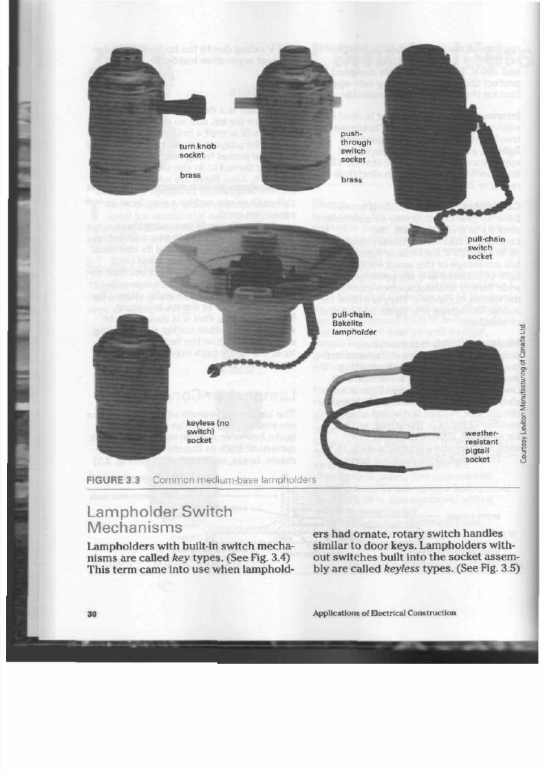
FIGURE 3.3 C omm on medium-base lampholders
Lampholder Swi tch
Mechanisms
Lampholders with built-in switch mecha
nisms are called key types. (See Fig. 3.4)
This term came into use when lamphold
ers had orna te, rotary switch handles
similar to door
keys.
Lampholders with
out switches built into the socket assem
bly are called keyless types. (See Fig. 3.5
30
Applications of Electrical Construction
8/19/2019 Applications Electrical
http://slidepdf.com/reader/full/applications-electrical 36/447
55
=8
E
>•
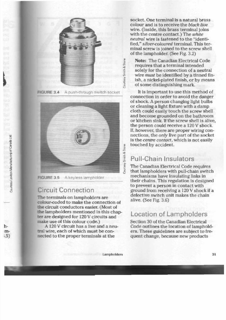
RGURE 3.4 A push-through switch socket
C/J
•8
RGURE 3.5 A keyless lampholder
Circuit Connection
The terminals on lamph olders are
colour-coded to make the c onnection of
the circuit con du cto rs easier. (Most of
the lampholders mentioned in this chap
ter are designed for
120 V
circuits and
make use of this colou r co de.)
A 120 V circuit has a live and a neu
tral wire, each of which m ust be con
nected to the p rope r terminals at the
socket. One terminal is a natural brass
colour and is to receive the black live
wire.
(Inside, this bras s terminal joins
with the centre contac t.) The
white
neutral wire is fastened to th e "identi
fied," silver<oloured term inal. This ter
minal screw is joined to th e screw shell
of th e lam pho lder. (See Fig. 3.2)
Note: The Canadian Electrical Code
requires that a terminal intended
solely for the con nectio n of a neutra l
wire must b e identified by a tinned fin
ish, a nickel-plated finish, or by means
of som e distinguishing m ark.
It is im porta nt to us e this m ethod of
connec tion in order to avoid the dan ger
of shock. A perso n cha nging light bu lbs
or cleaning a light fixture with a d am p
cloth could easily touch the screw shell
and become grounded on the bathroom
or k itchen sink. If the sc rew shell is alive
the perso n could receive a 120 V shock.
If, how ever, there are pro per wiring con
nections, the only live par t of the so cket
is th e centre contact, which is not easily
touched by accident.
1 P ull-C hain Insulators
>-
I Th e Canadian Electrical Code requ ires
J
tha t lam pho lders with pull-chain switch
mechanisms have insulating links in
their chains. This regulation is designed
to prevent a perso n in contact with
ground from receiving a 120 V shock if a
defective switch unit makes the chain
alive. (See Fig. 3.6)
Location of Lampholders
Section 30 of the Ca nadian Electrical
Code outlines the location of lamphold
ers.
The se guidelines are subject to fre
quent change, because new products
Lampholders
S

8/19/2019 Applications Electrical
http://slidepdf.com/reader/full/applications-electrical 37/447
2
£
I
>-
u
FIGURE 3.6 A pull-chain lampholder
and m aterials are constantly being intro
duc ed. When planning an installation,
make s ure to ob tain the latest edition of
the Code.
F o r R e v i e w
1. List th e five stan da rd screw -base
lampholder sizes, and give one
practical application for each.
2. W hat is the w attage rating for
incand escent lamps for the largest
screw-base lampholder?
3. Which electrical ratings for screw-
base
lampholders
are required by
the Canadian Electrical Code?
4.
W hy is bulb size for th e m edium-
bas e socket limited to 300 W?
5. List two type s of ad ap ters used
with light sockets.
6. What precaution is necessary
when using an adapter?
7. List the ty pes of lam pho lder
switch m echanism s. What is
mean t by the term keyless?
8. Explain
how
and why the conduc
tors from a 120
V
circuit must be
connected to a lampholder.
9. Why is an insulating link requ ired
in the c hain of one typ e of sw itch
mechanism?
10. W here can information be found
regarding th e installation of lamp-
holders?
32
A ppl icat ions of E lectr ica l Construct ion

8/19/2019 Applications Electrical
http://slidepdf.com/reader/full/applications-electrical 38/447
Receptacles
T
he receptacle is the m ost
widely used electrical device,
bec ause it is the point in a circuit at
which power may be taken to supply
lamps, appliances, or portable plug-in
devices. The residential recep tacle
delivers 120 V to any electrical device
plugged in to it. Every mo dern hom e is
equipped w ith a num ber of duplex
receptacles.
Receptacles are available in a variety
of quality and du ty ran ges. Light-duty
receptacles, frequently sold as
standard
or re sidential grade, may be used in
living-rooms or bedrooms, where a table
lamp
or radio will be the largest curr ent-
dem anding device plugged in. The
slightly b etter quality medium grade
receptacles stand up to somewhat more
frequent use in kitchens and utility
rooms. Heavy-duty rece ptacles, known in
the electrical industry as premium speci
fication grade, or often simply specifica
tion grade,
are much better designed and
con structe d. They are most suitable for
use in kitchen are as, wo rkshop s, and
industrial/commercial settings. Electric
frying pa ns, teakettle s, and ot he r fast-
heating appliances requiring a current of
12 A to 15 A benefit from being plugged
into heavy-duty rec epta cles : if a light-
duty receptacle were installed for such
appliances, it would he at up , the con
tacts would become soft and lose their
ability to grip the plug firmly, and dan
gerou s overh eating w ould follow. The
result would be damage to the recepta
cle, wiring, and plug.
Careful ad van ce plann ing is nec es
sary in order to prevent overloading of
receptacles. For trouble-free service, the
duty range of the receptacle should be
ma tched to the type of appliances
expected to rely on the outlet.
N um ber of O utlets on a
Circuit
Section 26 of the Canadian Electrical
Code outlines regulations for the instal
lation of recep tacles. The num ber of
outlets per circuit, the location, and the
number of outlets required for a given
room or location are discussed in detail.
With products and building standards
constantly changing,
only
th e Code can
be relied upon to provide a ccura te, up-
to-date information.
Receptacle Construction
There a re many sha pes and styles of
receptacles, but each has basic similari
ties
J"igure
4.1 shows the standard,
duplex, "U" ground receptacle found in
the modern home. This receptacle is
Receptacles 3

8/19/2019 Applications Electrical
http://slidepdf.com/reader/full/applications-electrical 39/447
l ive terminals (brass)
live slot
mount ing bracket
plaster
ears
(removable)
neutral slot
Bakelite case
cover mount ing screw
ground slot
mount ing h
grou nd terminal (gre
' "neutra l terminals (s i lver)
N O T E : A l l mo unt ing screws are #6-
FIGURE 4.1A Typical N E MA " U " ground receptacle
FIGURE 4.1B A 15 A , 125 V, specification
grade,
heavy-duty receptacle in NEMA
" U "
ground configuration
also widely used in office buildings,
stores,
and industry.
It
prov ides a firm
electrical connection for
120 V
equip
ment, toge ther with ground protection
for portable equipment.
Receptacle Combinations
Receptacles are available in single,
duplex, and
three-plug
units. The mo st
com mo n of all is the duplex receptac le,
which is designed to receive two electri
cal plugs. Some duplex units have one
half as a "U" ground and the other half in
a different sh ap e. Also, the re are rec ep
tacles team ed w ith switches, which
allow a light to be turned off either in t
room or at the receptacle itself.
Receptacle and Plug
Shapes
Figure 4.2 show s so m e of the configura
tions (shapes) of receptacles and plugs
that are available. There are many oth
ers made for specialized use. This
chapter discusses only the more
common ones.
Old-Style Two Prong.
Many building
con struc ted during the 1940s and
1950
were equ ipped with this unit. Th e main
disadvantage is the lack of ground
protection.
"U"
Ground. This recep tacle acce pt
both the 2 prong plug and th e 3 prong
"U" groun d plug. If th e g round prong is
remo ved from th e 3 prong plug, it will
still fit th e rec epta cle in one direction
only. Careful inspe ction of the rec ept ac
34 Applications of Electrical Construction

8/19/2019 Applications Electrical
http://slidepdf.com/reader/full/applications-electrical 40/447
old-sty le 2 prong
"U "
g r ound
3 prong twist - lock* direct -current* 240 V tan dem
©
©
©
©
©
©
drier recep tacle 30 A , 125 V / 250 V*
* polarized receptacles
FIGURE 4.2 Receptacle and blade patterns (configurations
range receptacle 50 A , 125 V / 250 V*
will show th at th e live and neutral slots
are different sizes to prevent inter
changing th e co nn ectio ns. (See Fig. 4.3)
Crow's Foot.
This plug was an early
attempt to provide ground protection in
a recep tacle. Unfortunately, the sh ap e of
the 2 prong plug could be modified with
pliers, allowing it to be fitted into the
receptacle. Also, the crow's-foot plug
often had its ground prong removed and
blades resh aped for use in standard 2
prong receptacle s. Ground protection
was lost in both cases. It became obvi
ous a change in design w as n eede d.
Twist-Lock.
This rece ptacle is
available in 2, 3, and 4 prong units. Its
major advantage is that the plug can
not be pulled out of the receptacle
accidentally. The 3 and 4 prong units
provide ground protection.
Receptacles
3
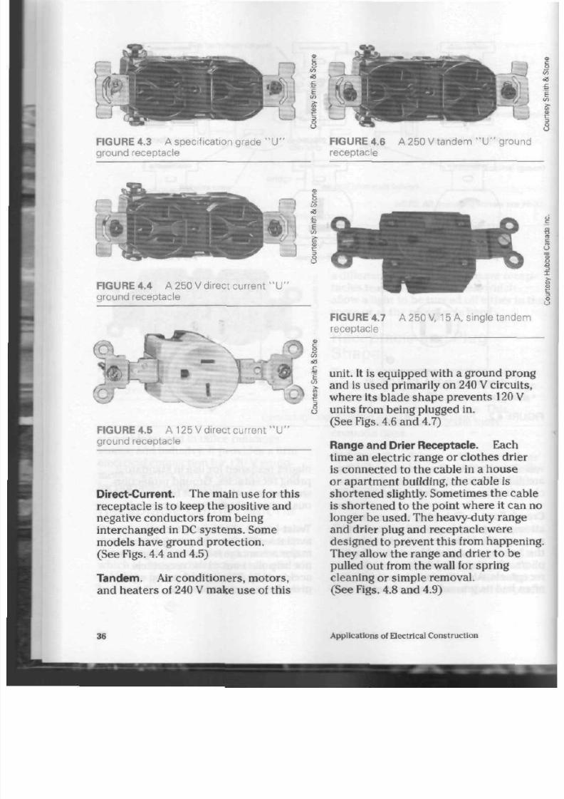
8/19/2019 Applications Electrical
http://slidepdf.com/reader/full/applications-electrical 41/447
FIGURE 4.3 A specif ication grade " U "
ground receptacle
FIGURE 4.6
receptacle
A 250 V tandem
" D "
ground
FIGURE 4.4
A
250
V direct current " IT
ground receptacle
FIGURE 4.5 A 125
V direct current "IT
ground receptacle
Direct-Current. The main use for this
recep tacle is to keep the positive and
negative conductors from being
interchanged in DC system s. Some
models have ground protection.
(See Figs. 4.4 and 4.5)
Tandem.
Air conditioners, motors,
and heaters of 240 V make use of th is
=3
e
g
o
FIGURE 4.7
receptacle
A 250 V
15
A, single tandem
unit. It is equipped with a ground prong
and is used primarily on 240 V circuits,
where its blade shape prevents
120 V
units from being plugged in.
(See Figs. 4.6 and 4.7)
Range and Drier Receptacle.
Each
time an electric range or clothes drier
is connected to the cable in a house
or apartmen t building, the cable is
shortened slightly. Sometimes the cable
is shortened to the point where it can n
longer be used . The heavy-duty range
and drier plug and receptacle were
designed to prevent this from happening
They allow the range and drier to be
pulled out from the wall for spring
cleaning or simple removal.
(See Figs. 4.8 and 4.9)
36
Applications of Electrical Construction

8/19/2019 Applications Electrical
http://slidepdf.com/reader/full/applications-electrical 42/447
\ ..." -
J L
i
IV)
•a
e
CO
FIGURE 4.8 A residential electric drier
\) receptacle
Commercial and industrial applica
tions often require voltages and c urr ent s
other than t ho se found in residential
applications. To prevent accidental
smatching of cord s and rec eptac les, a
•*ide variety of recep tacle configurations
has been ap proved by the Canadian
Standards Association (CSA). These can
be seen in Figures 4.10A and 4.1 OB o n
pages 38 and 39.
Receptacle Grounding
Receptacles equipped with a
ground slot
are designed to provide safety for the
person using the equipment connected
to the rece ptac le. If a fault occ urs in an
electric drill, for exam ple, th e cu rren t
will
travel to t he frame of th e drill, the n
back along the ground conductor to the
distribution panel. The circuit fuse in the
panel will blow a nd prev ent th e drill's
user from receiving a shock .
If
there is
no ground protection , however, the us er
could receive a 120
V
shock as the current
flow pa sse s from th e tool's frame thro ug h
the oper ator on its way to groun d.
The ground-equipped receptacle has
FIGURE 4.9 A residential electric range
receptacle, rated at 50 A
a green,
hex-shaped terminal screw
for
connection to the grounding circuit of
the electrical box that s upp orts the
recep tacle. The ground w ire in a non-
metallic or armoured cable wiring sys
tem runs between th e ground terminals
of the distribution panel, those of the
receptacle box, and the receptacle
itself.
A
metal conduit system carries the
ground connection from the distribution
panel to the receptacle box within its
metal easing.
A
flexible conduit system
usually requires a sep ara te, green, insu
lated conductor to be pulled into the
conduit to realize the same purpose.
These are Canadian Electrical Code
requirements.
Isolated Grounding
Receptacles
Some sensitive electronic equipment
such as cash registers, com puters, and
medical instruments will perform poorly
if any electromagnetic interference
passes through their regular grounding
circuits. However, special re cepta cles,
Receptacles

8/19/2019 Applications Electrical
http://slidepdf.com/reader/full/applications-electrical 43/447
125 V
15 ampere
D Qw)
5 - 1 5 R
20 ampere
5-20R
30 ampere
7 \
(
0
•aw)
5-30R-
50 ampere
[
D
Qw)
5-50R
60 ampere
S
'•a
B
o
•
i
a
o
a
250 V
6 - 15R
©
6-20R
o
-30R
6-50R
277 V
A C
7 - 1 5 R
7-20R
U
^
7-30R
v
ft
# y
7-50R
24
347 V
A C
24-15R 24-20R
24-30R
24-50R
if
9
P
14
125
V /
250 V
1 4 - 1 5 R
1 4 - 2 0 R
1 4 - 3 0 R
14 - 50R
1 4 - 6 0 R
15
3 0
250 V
1 5 - 1 5 R
1 5 - 2 0 R
1 5 - 3 0 R
1 5 - 5 0 R
1 5 - 6 0 R
NO TE : 3 0 refers to a 3 phase system. The "Y" symbo l s igni f ies a 3 phase, 4 wire W ye-connected system
FIGURE 4.10A CS A configurations for non-locking cord caps and receptacles
Applications of Electrical C onstruction
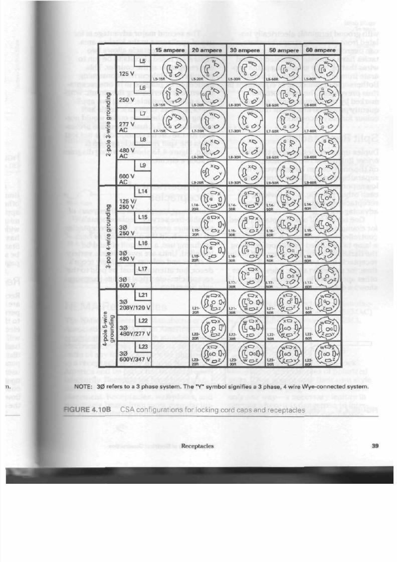
8/19/2019 Applications Electrical
http://slidepdf.com/reader/full/applications-electrical 44/447
15 ampere 20 ampere 30 ampere 50 ampere
60 ampere
L5
125
V
c
'•&
c
3
O
o>
V
CO
o
a.
L6
250 V
L7
277 V
A C
L8
480 V
A C
L9
600 V
A C
_c
c
D
O
5 >
Q>
L14
125 V/
250 V
L15
3 0
250 V
L16
3 0
480 V
L17
3 0
600 V
L21
3 0
208Y/120V
<B
P
g
9- o>
L22
3 0
480Y/277 V
20R
L22 \
Z
0
L23
3 0
600Y/347
V
( < 3
G O
0 /
50R
N O T E :
30 refers to a 3 phase system. T he "Y" symb ol s ignif ies a 3 phase, 4 wir e Wye-connected system.
RGU RE 4.10B CS A configurations for locking cord caps and receptacles
Receptacles
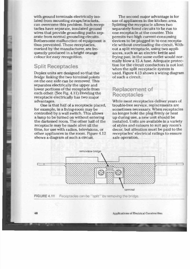
8/19/2019 Applications Electrical
http://slidepdf.com/reader/full/applications-electrical 45/447
with ground terminals electrically iso
lated from mounting straps/brackets,
can overcome this problem. Such recep
tacles have separate, insulated ground
wires that provide grounding pa ths sep
arate from normal grounding circuits.
Bothersome malfunction of equipment is
thus p revented. These receptacles,
marked by the manufacturer, are fre
quently produced in a bright orange
colour for easy recognition.
Split Receptacles
Duplex units are designed so that the
bridge linking the two terminal points
on the one side can be removed. This
separates electrically the upper and
lower portions of the receptacle from
each other. (See Fig.
4.11)
Dividing the
receptacle electrically has two major
advantages.
One is that half of a receptacle placed,
for example, in a living-room may be
controlled by a wall switch. This allows
a lamp to be turned on without entering
the darkened room. The other half of the
receptacle may be made alive all the
time, for use with radios, televisions, or
other appliances in the room. Figure 4.12
shows a diagram of such a circuit.
The second major advantage is for
use of appliances in the kitchen area.
Splitting th e receptacle allows two
separa tely fused circuits to be run to
one receptacle at the counter. This
permits two high current-consuming
devices to be plugged in to one recepta
cle without overloading the circuit. Wi
out a split receptacle, using two appli
ances, such as an electric kettle and
frying pan, in the sam e outlet would no
mally blow a 15 A fuse. Adequate prote
tion for the circuit conductors is not lo
when the split receptacle system is
used . Figure
4.13
shows a wiring diagra
of such a circuit.
Replacement of
Receptacles
While most receptacles deliver years o
trouble-free serv ice, replacements are
sometimes necessary. When receptacle
no longer hold the plug firmly or heat
up during use, a new unit should be
installed. Units are available in a variety
of styles and colours to suit any room's
decor, but attention must be paid to th
receptacles' electrical ratings to ensure
safe operation.
removable bridge
i—r
terminal
FIGURE 4.11 Receptacles can be "s p l i t " by removing the bridge.
40
Applications of Electrical Construction
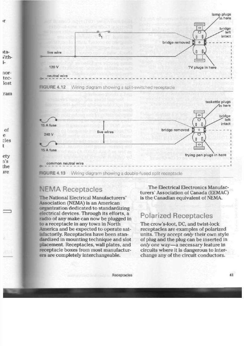
8/19/2019 Applications Electrical
http://slidepdf.com/reader/full/applications-electrical 46/447
l ive wire
lamp plugs
In here
br idge
' left
intact
br idge removed
120 V
neutra l wire
TV plugs in here
RGURE 4.12 W iring diagram show ing a split-switched receptacle
teakett le plugs
here
bridge
' left
intact
live w ires
bridge removed
yy
15 A fuse
common neutra l wire
1 = 1
frying pan plugs in here
SURE 4.13 W iring diagram show ing a double-fused split receptacle
NEMA Receptacles
The National Electrical Manufacturers'
Association (NEMA) is an Am erican
organization dedicated to standardizing
electrical dev ices. Through its efforts, a
radio of any m ake can now b e plugged in
to a receptacle in any town in N orth
.America
and be expected to op erate sat
isfactorily. Receptacles have been stan
dardized in mo unting techniq ue and slot
placement. R eceptacles, wall plates, and
receptacle boxes from most manufactur
ers are completely interch angeab le.
The Electrical Electronics Manufac
tu re rs ' Association of Can ada (EEMAC)
is the Canadian equivalent of NEMA.
Polarized Receptacles
The crow's-foot, DC, and twist-lock
recep tacles are examples of polarized
units. They accep t
only
their own style
of plug and the plug can be inserted in
only one way—a
necessary feature in
circuits where it is dangerous to inter
change a ny of the circuit co ndu ctors .
Receptacles
4

8/19/2019 Applications Electrical
http://slidepdf.com/reader/full/applications-electrical 47/447
Plaster E ars
Many receptac les are equipped with
small extensions to the mounting
bracket called plaster ears. When a
receptacle is installed in a building with
plastered walls or wood panels,
plaster
ears are ve ry useful.
Plaster
around the
receptacle box often crumbles, leaving
a
space with little
or
no support
for
the
receptacle. The
plaster
ear extensions
provide extra length and width to the
moun ting bracket, making possible a
sec ure , flush m oun ting. (See Fig. 4.14)
Receptacle installations in surface
wiring boxes, suc h a s th e utility box
or
FS fitting, do nor require plaster ears.
(See
Fig. 4.15)
Removal
of
the ears
is a
simple mat
ter. Bend them back and forth several
times w ith a pair of pliers.
Ground Fault Interrupter
Receptacles
Modern wiring regulations require out
door receptacles
to be of
th e Ground
Fault Interrupter
(GF1) typ e. C onsult th
Electrical Code for your area to deter
mine exactly wh ere the se units must
be
installed. The
GFI
receptacles are
designed to protect users of portable
tools and equipment from electrical
shock, which can occu r if the tool or
equipment becomes faulty. Each year,
m any pe ople are killed
or
endangered
b
the p ortable electric devices that have
developed internal defects or insulatio
breakdowns.
It
is not always obv ious
to
the operator that this breakdown has
occurred until the device is plugged in
and
a
shock received.
Normal fuses and circuit breakers
will no t blow
or
trip unless the curren t
flow to ground (earth) exceeds the
ampere rating
of
the protection device
They are designed
to
protect
a
circuit's
wire, NOT th e pe rson using the circuit.
GFI rece ptac les are designed to detect
small leakage cur ren ts when the y de
velop and trip open t he circuit to prote
the person using that circuit. Currents
as low as
5
mA (0.005 A) can
be
sensed
by the unit when it is pro perly installed
#6-32 mount ing screw
bare ground wire
15 cm wire
m m
chipped or broken plas
near b
plaster w
sect ional
plaster
Plaster
reaches solid mater
FIGURE 4.14 Flush-mounting a receptacle using
plaster
ears
42 Applications
of
Electrical Construction
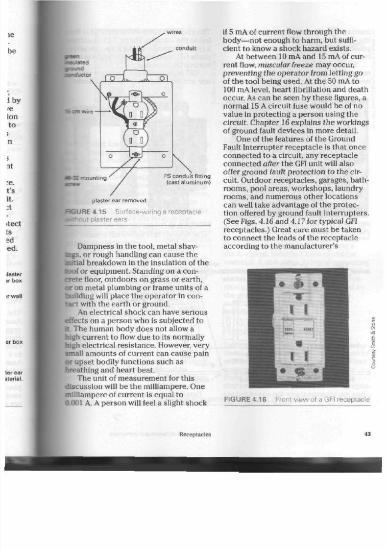
8/19/2019 Applications Electrical
http://slidepdf.com/reader/full/applications-electrical 48/447
wires
conduit
V o n w ire
5-32 mount ing
FS condu it f i t t ing
(cast a luminum)
plaster
ear removed
RGURE
4.15
S urface-wiring a receptacle
it plaster ears
Dam pness in the tool, metal shav
ings,
or rough handling can cause the
nitial
breakdow n in th e insulation of th e
tool or eq uipm ent. Standing on a con
crete floor, ou tdo ors on g rass or ea rth,
or on m etal plum bing or frame un its of a
building will place th e o pe rato r in con
tact with the earth or ground.
An electrical shock can hav e serious
effects o n a person w ho is subjected to
L The human body does not allow a
current to flow due to its normally
high electrical resistance. However, very
small amounts of current can cause pain
or upset bodily functions such as
breathing and heart beat.
The unit of measurement for this
dfecussion will be the milliampere. One
milliampere of curre nt is equ al t o
0.001 A. A person will feel a slight shock
if 5 mA of current flow through the
body—not enough to harm, but suffi
cient to know a shock haza rd e xists.
At between 10 mA and 15 mA of cu r
rent
flow, m uscular freeze
may occur,
preven ting th e op era tor from letting go
of the tool b eing us ed. At th e 50 mA to
100
mA
level, he art fibrillation and de ath
occur. As can be seen by th es e figures, a
normal 15 A circuit fuse would be of no
value in protecting a perso n u sing the
circuit. Chap ter
16
explains the w orkings
of ground fault d evic es in m ore d etail.
One of the features of the Ground
Fault Interrupter rec eptac le is that onc e
connected to a circuit, any receptacle
connected
after
t he
GFI
unit will also
offer ground fault protection to the cir
cuit. Outdoor receptacles, garages, bath
rooms, pool areas, workshop s, laundry
rooms, and num erous other locations
can well take adva ntage of the p rotec
tion offered by ground fault interrupters.
(See Figs. 4.16 and 4.17 for typ ica l GFI
receptacles.) Great care must be taken
to connect the leads of the receptacle
according to the manufacturer 's
FIGURE 4.16 Front vie w of a GFI receptacle
Receptacles
43

8/19/2019 Applications Electrical
http://slidepdf.com/reader/full/applications-electrical 49/447
instructions. If connected incorrectly,
the GFI recep tacle will not prov ide th e
pro tect ion d esired . Figure 4.18 illus
trates a typical wiring diagram.
Some manufacturers produce a GFI
receptacle that uses terminal screw con
nections rather than connection leads.
The choice of connection m ethod is then
left to t he installer. Figure 4.19 illustr ates
a typical comm ercial-duty, specification
grade GFI, suitable for both vertical and
horizontal m ounting.
GFI receptacles are equipped with
test and reset butto ns. The unit should
FIGURE 4.17 Rear vie w of a GFI recep tacle, FIGURE 4.19 A comm ercial-duty, specifica-
show ing the connection leads tion grade ground fault protection receptacle
and cover plate
splice
black lead
GFI
receptacle
green lead
splice
f \ V U U \ U V
CZI
I—I
a
test
I
|
reset
C
black wires
/ \ to next receptacle
i
•
Insulate ends of red and
•
grey if no othe r receptacles
are to be connected.
B [
standa rd receptacle
gr ound
white lead
neutral wire
o
"splice grey
lead
splice
\ /
whi t e w i r es
gr oun
to next receptacl
to next receptac
FIGURE 4. 18 C onnection diagram for a GFI receptacle installation
44
Applications of Electrical Construction

8/19/2019 Applications Electrical
http://slidepdf.com/reader/full/applications-electrical 50/447
in
fiGURE 4.20 A typical electric shaver outlet
be tested at least once a mo nth by pres s
ing th e test butto n on th e face of th e
rece ptac le. This simulates a ground fault
in the circuit and the relay within t he
receptacle should react and open the
rrcuit. The reset button will at this time
protrude from the face of the receptacle,
indicating successful operation of the
unit. Pressing the reset b utton back into
place will reactiva te the relay in th e
recep tacle for further us e. This simple
test assu res the owner tha t the unit is in
proper working order.
Prior to recent GFI developm ents,
electric shave r recep tacles tha t isolated
the supply voltage from t he shav er w ere
available. This eliminated the sh ock haz
ard present wh en electric shaving equip
ment was used near plumbing fixtures.
These recep tacles were, however, too
small (electrically) for use with m od ern
hair dr ier s. (See Fig. 4.20)
Hospital Grade Grounding
Receptacles
Receptacles in hospitals and oth er m edi
cal facilities are often subjected to
severe use and mechanical ab use. When
an emergency oc cu rs or a life is at sta ke,
time becom es im porta nt. Medical staff
will frequently move plugged-in pi eces of
green dot
FIGURE 4.21 A 125 V " U " ground recepta
cle of hospital grade, identified by a green dot
on the lower face
equipment about, causing unintentional
abuse to both the cord connector and
receptacle.
Hospital grade receptacles are made
from a
heavy-duty,
abuse-resistant ther
mo plastic, capab le of w ithstanding
impact d amage, while resisting the tend
ency to crack or break. The possibility of
sho rt circuits is reduced by having a
thick-walled, mou lded ba se of similar
material. A one-piece, integral groun ding
contact ensures proper grounding of the
circuit and equipment being used. Hos
pital grade rec eptac les ar e identified by
the green dots on the ir faces, visible
even when their cover plates are
insta lled . (See Fig. 4.21)
Receptacle Covers
Indoor receptacles use standard-sized
metal or plastic covers when installed in
resid entia l c ircu its. (See Fig. 4.22) When
covers are used outdoors or in other
dam p areas, they should be the type
that provides easy access to the recepta
cle but keeps out weather-m oisture and
dirt. (See Fig. 4.23)
Receptacles
4

8/19/2019 Applications Electrical
http://slidepdf.com/reader/full/applications-electrical 51/447
3
0)
FIGURE 4.22 Indoor receptacle and cover
FIGURE 4.24 C ombination sw itch and
receptacle unit
device in another area of the room or
building . See Figure 4.24 for a typica l
unit.
FIGURE 4.23
cover
Weather-resistant receptacle
Combination Units
When installation sp ac e is limited, a unit
that allows an installer to locate the
switch and rece ptacle in the sam e single
gang box is recom m ended . The switch
can either control the receptacle portion
of the unit, a light fixture, or a no the r
F o r R e v i e w
1. W hat duty ra nge of rece ptacle
should be selected for kitchen
use? Why?
2.
Where in the home may light-duty
receptacles be safely installed?
3. Where can information be found
regarding the num ber of recepta
cles required for a room?
4. E xplain wh ere th e live, neutral,
and ground wires are connected
on a duplex "U" ground
receptacle.
5.
List two us es for a switch and
receptacle combination unit.
6. What is the main disad van tage of
the old-style 2 prong receptacle?
7. Would an extens ion cord fitted
with twist-lock units be an advan
tage on a constru ction job site?
Why?
8. Explain the purpose of the ground
slot on a receptac le.
9. Where does th e ground in a recep
tacle originate?
46
Applications of Electrical Construction
8/19/2019 Applications Electrical
http://slidepdf.com/reader/full/applications-electrical 52/447
10.
How is the g round circuit carried
in a conduit system ?
11.
What is the d ang er in using a po r
table electric tool that has had the
grounding prong removed from its
plug? Explain.
\2 .
List two are as for use of split
receptacles in the h om e.
[13.
What are the adv antage s of using
split receptacles?
11
What is a
NEMA
receptacle?
Explain.
ist three examples of polarized
receptacles.
16.
What are
plaster
ears? W here and
why are they used?
17.
What type of receptacle is recom
mended by the Electrical Code for
use in outdoor areas?
|18.
What advantage has a
GFI
recepta
cle over o the r ty pes of
receptacles?
19.
Why will a norm al fuse or c ircuit
breaker not protect a person using
portab le tools on a circuit?
120.
Why is it imp orta nt for a
GFI
unit
to detect leakage currents as low
as 5
mA?
Receptacles
4
8/19/2019 Applications Electrical
http://slidepdf.com/reader/full/applications-electrical 53/447
Conductors
O
ne of the most imp ortant pa rts of
any electrical system is the co ndu c
tor that makes up the wiring circuit.
Most con duc tors are rarely check ed
after the installation h as been appro ved.
For this reason and o ther s, the ch oice of
conductor is an important feature of cir
cuit design.
Conductor Materials
Conductors used for residential and
industrial wiring circuits are usually
m ade from co pper, aluminum, or steel. If
exposed to the air, thes e metals co mb ine
with the oxygen. This
oxidation
pro
duc es a layer of oxide on th e surface of
the conductor. If a conductor is allowed
to oxidize at the terminal point or splice,
the current-carrying ability of the termi
nal will be seriously reduced. That is
because the oxide layer does not con
duct electricity.
Copper.
Co nduc tors are often m ade of
copper, because it is an excellent
condu ctor, easy to work with and
hand le, and do es not oxidize as mu ch as
aluminum o r steel. Copper is also u sed
in electronic circuits bec ause it solders
readily, ensuring a secure electrical
connection. Copper has beco me
expensive, however, and a sub stitut e is
being sought.
Copper w ire
splices
must be mad
secu re to preven t the oxide coating f
reducing the current-carrying ability
the splice.
Aluminum.
Aluminum is lighter th
cop per but not as good a condu ctor.
obtain the same current-carrying
capacity, therefore, an aluminum
con duc tor mu st be slightly larger tha
one made of copper. Also, aluminum
oxidizes rapidly. The aluminum oxide
acts as an insulator and reduces
electrical c urr en t flow.
Using aluminum po ses two othe r
major proble ms . One is
electrolysis,
which is the chemical breakdown of
metals reacting with one another. Alu
num will react with some metals in th
way. The p roce ss is accelerated by m
ture and th e flow of curre nt in the con
ductors. Approved connection devic
resist this proce ss, and s o approv ed
minal splice connectors should be us
Also,
antioxidant chem icals
to preven
oxidation of th e wire are available.
Th ese chemicals a re usually applied
with a brush, forcing the chemical in
the stran ds of the cab le. Figure 5.1 il
trates a typical chemical available fo
this purpose.
The second major problem with a
minum conductors is that the connec
48
Applications of Electrical Construction

8/19/2019 Applications Electrical
http://slidepdf.com/reader/full/applications-electrical 54/447
RGURE 5.1 A ntioxidant chemical for use on
num conductors
nints lose their grip.
A
terminal screw
can be tigh tened firmly, but in a few
days,
the aluminum will accept th e new
shape into which it has been forced.
fhis
reduces the pressure of the termi
nal
screw on the wire, and th e aluminum
lo w s in to the new shape. This
flow—
called
cold flow—results
in a loosened
conne ction. As a result, the terminal
connec tion will overheat, causing dam
age to the connec tion and insulation.
If han dled prope rly, aluminum is an
c&ctive
cond uctor that provides many
years of servic e. It is not of much use ,
however, for circuits where solder con
nections are necessary, because alumi-
•um cannot be soldered simply.
Steel. Steel is the stro ng est of th e
three metals and is used mainly as a
supp orting material. For example, alumi
num and copp er cables are often wound
around a steel centre core for outd oor
wiring. Con ductors m ade this way can
withstand a great deal of stress. Also,
electric railway or subway syste m s often
use steel rails as the con duc tors in their
supply system . The rails are som etimes
made of special steels containing a small
amount of copper to improve the cur
rent-carrying ability of th e rails.
While the metal conduit and boxes
are
not
used to carry current for the
operation of electrical equipment, steel
enclosures
are
used to complete the
groun ding circuit. In rural serv ice instal
lations, for example, two steel rods are
often driven into the ground to provide
a ground connection w here there is no
metal water supply system to the
building.
Conductor Forms
Co nduc tors used for residential and
industrial wiring circuits are made in the
form of wire, cable, and cor d.
W ire. W ire, wh ich is a single, solid
strand, is the least flexible form of
conductor.
Copp er wire is usually m ade by
drawing
a soft co pp er rod, which is from
6 mm to
13
mm in diameter, through a
series of doughnu t-shaped metal blocks
called
dies.
Th e hard cen tre of each die
ha s a hole slightly
smaller
than the hole
of the die through w hich the rod h as jus
been draw n. As the rod p ass es throu gh
the dies, it is reduced in diame ter and
lengthened.
The wire ten ds to hard en after p ass
ing through several dies. This hard-
drawn copper is used for some outdoor
wires bec aus e it is quite strong.
If the diam eter n eed s to b e m ade stil
Conductors
4

8/19/2019 Applications Electrical
http://slidepdf.com/reader/full/applications-electrical 55/447
low voltage thermos tat (LVT) contro l wire 2 conductor
C A N A D A WtRK
annunciator wire
blast ing wire
asbestos-insulated stove wire
low voltage con tro l wire (LVT) 3 conductor
P O L H T M Y L H I B L I N K WI RR
polyethylene l ine wire
thermoplast ic- insulated wire
FIGURE 5.2 Typical insulated wire s
50
Applications of Electrical Construction

8/19/2019 Applications Electrical
http://slidepdf.com/reader/full/applications-electrical 56/447
therm oplast ic- in sulated , weather- and heat-resistant cable
therm oplas t ic- insu lated, weather- and heat-resistant cable
f lexib le we ld ing cable
E XE LE NE 6 0 0 V O L T S
service entrance cable
* #
, m
^ ^^^"A ^ 4.
,
* ^ , % ^ ^ ^ . ^ f c ^ - .
,
* ^ - ^ % *.
armoured cable
•™*—
turn**,
nonmetallic sheathed cable
CURE 5.3 T ypical insulated cables
Conductors

8/19/2019 Applications Electrical
http://slidepdf.com/reader/full/applications-electrical 57/447
lamp cord
n
/i
HPN (chlorinated polyethylene) heater cord
^ ^ r "J*?^™?
wffrf:JL
,B
/3 SJTW outdoor cord
TYPE SJ 300 VOLTS
light-duty cord for small motors and tools
heavy-duty, type SO power supply cord
FIGURE
5.4 Typical light- and heavy-duty
insulated
cords
52
Applications of Electrical Construction

8/19/2019 Applications Electrical
http://slidepdf.com/reader/full/applications-electrical 58/447
smaller, th e wire is first p ass ed throu gh
•
annealing
oven, which heats and
oftens it. The wire can then be further
edu ced to any size required. The
me aling process m ay have to be
irpeated several times. The wire may
asso be insulated w ith a varie ty of
•aterials. (See Fig. 5.2 on page 50.)
Aluminum wire is produced in the
way.
Cable. A cable is a
compound
mductor
m ade of a num ber of str an ds
*
wire. Some are twisted tog ether to
farm a large conductor before being
iasulated.
This typ e is usually u sed in
circuits w he re th er e is a large flow of
current.
Others are assembled and
placed under a common cover after each
•ire has been insu lated. This type is
ased extensively for the wiring
of
ildings . (See Fig. 5.3 on page
51.)
A
cab le is mo re flexible th an a wire of
i
same size.
Cord. The cord 's con duc tors are
Bade
of man y str an ds of fine wire
risted together. The cord is ma de of
•JPD
or m ore separately insulated
iductors
assembled within an
iting
jacket. It is th e m ost flexible
i
of condu ctor an d is used to supp ly
ait
to hand-held app liances and
rtable to ols, where freedom of
ovement
is importa nt. Appliance and
I
cords som etimes have a third
iuctor (with green insulation),
:h is used for grounding. (See Fig.
•
inductor Sizes
iductor
sizes are me asured and listed
i
two ways. One meth od is based on the
^•erican
Wire Gauge. The oth er is
fcased on area.
FIGURE 5.5 A merican W ire Gauge used to
measure size of solid conductors (wires)
Am erican Wire Ga uge (AWG). This
gauge is used to m easure only
solid
co nd uc tors (wire). The outer edge of th e
gauge has slots, which are num bered.
The
smallest slot
into wh ich t he w ire wil
fit is the
gauge number
of the wire . (See
Figs. 5.5 and 5.6) The
AWG
can m easure
wire from No. 36 (the sm allest size) t o
No.
0 (the largest size).
wire
gauge
wire in slo
gauge number
FIGURE 5.6 Using the A merican W ire
Gauge
Conductors
5
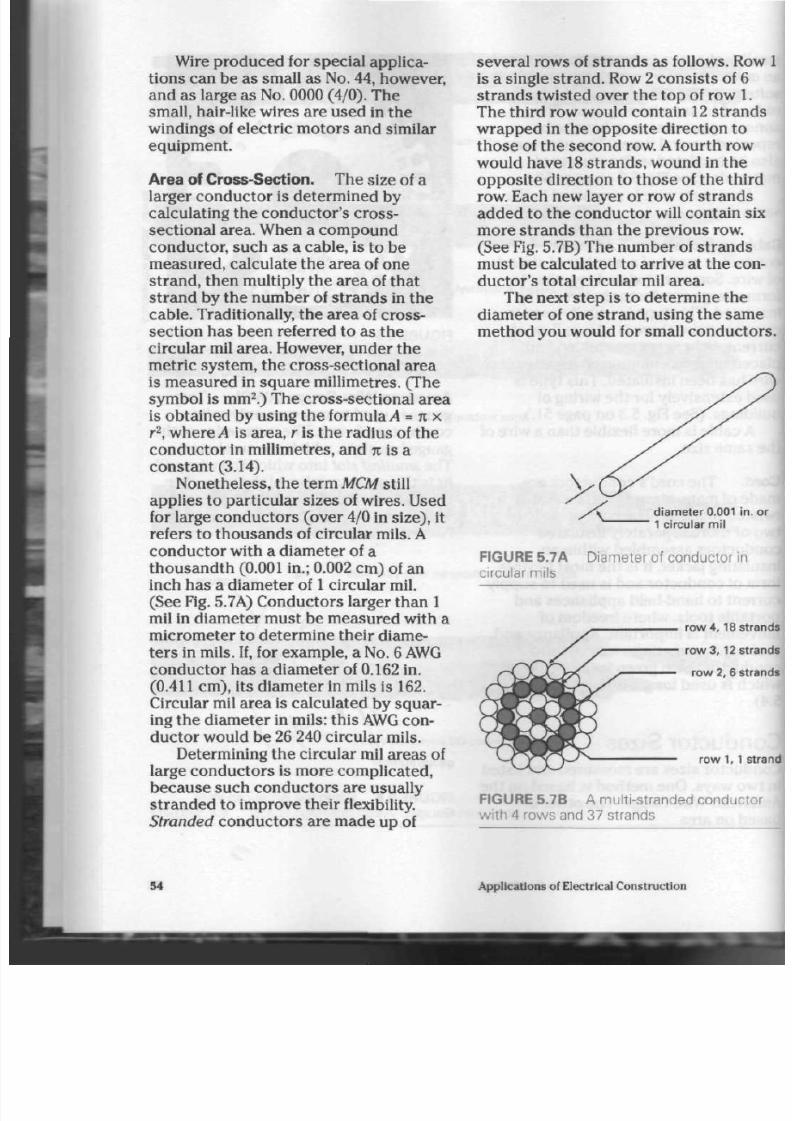
8/19/2019 Applications Electrical
http://slidepdf.com/reader/full/applications-electrical 59/447
Wire produced for special applica
tions c an be as small as No. 44, however,
and as large as
No.
0000 (4/0 ). The
small, hair-like wires a re used in the
windings of electric motors and similar
equipment.
Area of Cross-Section.
Th e size of a
larger conductor is determined by
calculating the conductor's cross-
sectional area. When a com pound
conductor, such as a cable, is to be
mea sured, calculate the area of on e
strand , then multiply the area of tha t
strand by the number of strands in the
cable . Traditionally, the a rea of cro ss-
section has been referred to as the
circular mil area. However, und er th e
metric system, the cross-sectional area
is m easured in squa re m illimetres. (The
symbo l is mm
2
.) The cross-sectional area
is obtained by using the
formula A = n
x
r
2
, where
A
is area, r is th e rad ius of t he
con duc tor in millimetres, and
it
is a
constant (3.14).
Non etheless, the term
MCM
still
applies to p articula r size s of wires. Used
for large co nd uc tor s (over 4/0 in size), it
refers to thousands of circular mils. A
con duc tor with a diam eter of a
thousandth (0.001 in.; 0.002 cm ) of an
inch has a diameter of 1 circular mil.
(See Fig. 5.7A) C ond ucto rs larger tha n 1
mil in diameter must be measured with a
micrometer to determine their diame
te rs in mils. If, for example, a N o. 6 AWG
co nd uct or has a diam eter of 0.162 in.
(0.411 cm), its diam eter in mils is 162.
Circular mil area is calculated by sq uar
ing the diam eter in mils: this AWG con
du cto r would b e 26 240 circular mils.
Determining the circular m il area s of
large conductors is more complicated,
becau se such condu ctors are usually
stranded to improve their flexibility.
Stranded
con duc tors a re mad e up of
severa l row s of st ran ds as follows. Ro
is a single stran d. Row
2
co nsi sts of 6
stra nd s twisted over the to p of row 1.
The third row would con tain
12
stran
wrapped in the opposite direction to
tho se of the seco nd row.
A
fourth row
would have
18
strands, wound in the
opp osite direction to thos e of the thir
row. Each new layer or row of str an ds
add ed to th e con duc tor will contain s
more strands than the previous row.
(See Fig. 5.7B) Th e num ber of str an ds
mu st be calculated to arrive at the co
ductor's total circular mil area.
The next step is to determ ine the
diam eter of one stran d, using the sa m
method you would for small conducto
1 circular mil
FIGURE 5.7A Diameter of conductor in
circular mils
row 4, 18 str
row 3,12
str
row 2, 6 str
row 1, 1 s
FIGURE 5.7B A multi-stranded conducto
w ith 4 rows and 37 strands
54
Applications of Electrical Construction
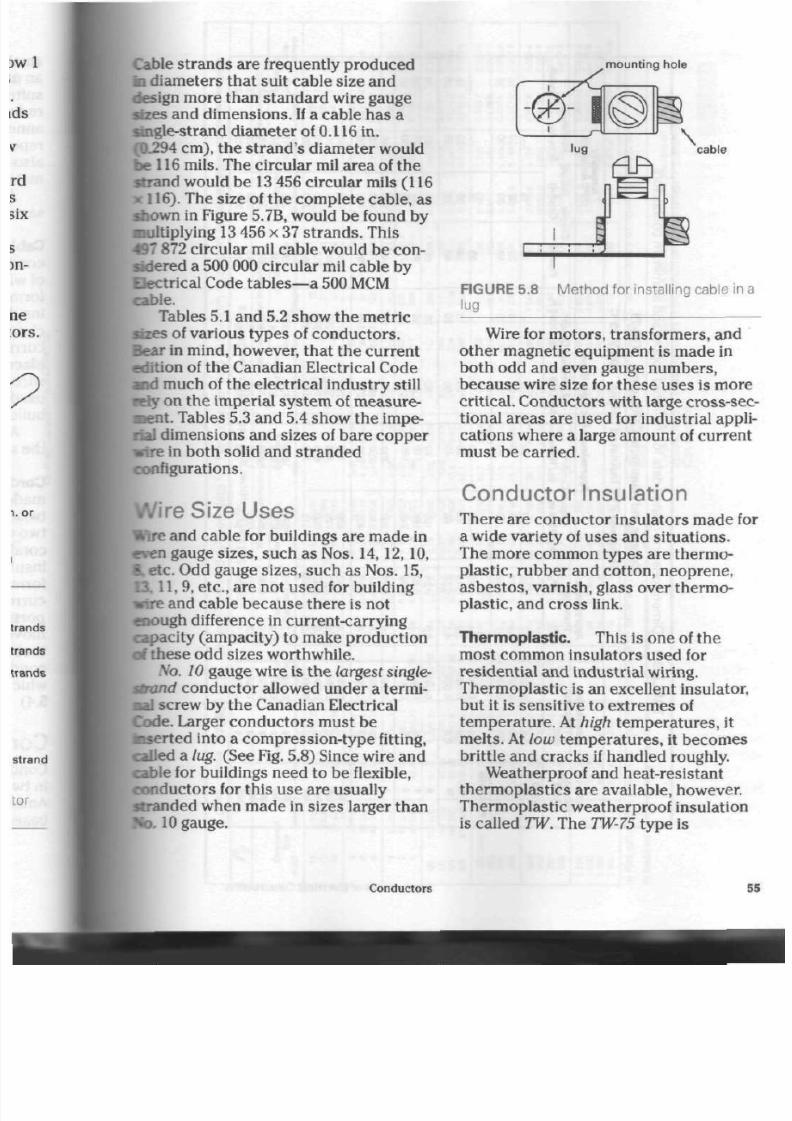
8/19/2019 Applications Electrical
http://slidepdf.com/reader/full/applications-electrical 60/447
Cable stran ds are frequently produ ced
ID diameters that suit cable size and
design more than stand ard wire gauge
sizes and d im ensio ns. If a cable ha s a
single-strand
diam eter of 0.116 in.
(0.294 cm), the stra nd's diam eter would
be 116 mils. The circular m il area of th e
strand would be
13
456 circu lar mils
(116
K 116). The size of the com plete cab le, as
shown in Figure 5.7B, would be found by
multiplying 13 456 x 37 strand s. This
497 872 circular mil cab le wou ld b e con
sidered a 500 000 circular mil cable by
Electrical Code tables—a 500 MCM
cable.
Tables 5.1 and 5.2 show th e m etric
sizes of various types of co nd ucto rs.
Bear in mind, however, that the current
edition of the Canadian Electrical Co de
and much of the electrical industry still
•efy on the imperial syste m of m easure-
saent. Tables 5.3 and 5.4 sh ow the impe
rial dimensions and sizes of bare copper
•ire
in both solid and stranded
configurations.
Wire Size Uses
Wire and cable for buildings are m ade in
wen gauge sizes, such as Nos. 14,12,10 ,
L
etc. Odd gauge sizes, su ch as N os. 15,
1,9, etc., are not used for building
wire and cable becaus e the re is not
enough difference in current-carrying
capacity (ampacity) to make production
of thes e odd sizes worthw hile.
No.
10 gauge wire is the larg est single-
strand conductor allowed under a termi-
aal
screw b y the Canadian Electrical
Code. Larger con duc tors must be
taserted into a compression-type fitting,
called a lug. (See Fig. 5.8) S ince w ire and
cable for buildings need to be flexible,
con duc tors for this use are usually
strande d w hen m ade in sizes larger than
No.
10
gauge.
mount ing hole
cable
FIGURE 5.8 Me tho d for installing cable in a
jug
Wire for motors, transformers, and
oth er m agnetic equipm ent is mad e in
both odd and even gauge numbers,
beca use wire size for these uses is more
critical. Co ndu ctors with large cross-sec
tional areas are used for industrial appli
cations w here a large amount of curre nt
must be carried.
Conductor Insulation
There are conductor insulators made fo
a wide variety of uses and situations.
The more common types are thermo
plastic, rubber and cotton, neoprene,
asbestos, varnish, glass over thermo
plastic, and c ros s link.
Therm oplastic. This is one of the
most common insulators used for
residential and industrial wiring.
Thermoplastic is an excellent insulator,
bu t it is sensitive to ex trem es of
tem perature. At high temperatures, it
m elts. At lo w temp eratures, it becom es
brittle and cracks if handled roughly.
Weatherproof and heat-resistant
therm oplastics are available, however.
Thermoplastic weatherproof insulation
is called
TW .
The
TW-75
type is
Conductors 5

8/19/2019 Applications Electrical
http://slidepdf.com/reader/full/applications-electrical 61/447
o
CJ
3
T 3
C
o
o
c
E
3
CO
c
CO
0
D.
Q.
O
U
T 3
<L>
-*-
1
JO
3
/>
o
H—
CO
->
O
" O
0
4 3
CO
CD
" O
c
CO
CO
c
C/>
c
CD
E
Q
i n
L U
OQ
<
H
m
r»
p
12
o
3
•o
c
o
o
E
3
e
"i
3
<
C
CO
s
a
a
0
o
o
UD
r»
>
o
s
(A
(1)
A
IB
o
-o
u
1
HI
c
V)
0)
E
IS
u .
-
c
P
h
i/t
i
5
3
3
«»
•
i
E
S
a
a
<
£
3
•o
c
cS
E
3
C .
1 3
2
•
<
2
L L
a
Is
1*
.
O
1
•
£
«
i i
- ^
3 5
E
3
3 X
< ?
»
C
s
t s
' ~T
£
-D
o —
u
ii
5 |
)
2 c
11
I
5
I
| 1
J
11
3
°
W i
E
•
°2
i i n ID
| « - C M
, O O
CN C O
mo o
i - M f l
o i n o
CN Csl \ t
•
in O
| - w
i i n o
1 CM co
o lO o
CM CM ^ f
o
i n
o
CO CO CD
CO
^
CO
o d d
C N C D C N
CO CO « t
CO CO CO
o o o
o d d
CO CO CO
o d d
9 *
N
o
8 '
, i n i n
| « - C N
| C N CO
i n
o o
i—
C N C O
o i n p
C N C N ' t
. i n o
t— C N
. i n
o
C N C O
o o o
C N C O ^ t
o
m
o
c o ^ r
C D
c o
i n co
d o d
» * o> in
C O C O * » '
o o o
CO CO CO
o o
p
o d d
CO CO CO
o d d
a
•
a
1
o o i n
c o i n C D
i n i n o
* r
r-
o
i n i n i n
^ C O C O
i n i n i n
co c n CN
i n i n i n
c o m r -
o o o
i n
c o t *
o o i n
r - « - c o
o
i n i n
O CO 1
t -
i - CN
•»om
N C O C O
o d d
o r - r-
(6
r- i
c d
i n o o
1 C D I D
o o o
o d d
« -
i n i n
M (B *
£ 8 g
r
i n i n I D
•-
co m
p
i n
o
o * - CO
i n o i n
•<J
r-
en
g § §
o o o
CO CO
i -
« - * - CM
o
o
o
O ^ CN
CN
<N
CO
o o o
8S3
CO — O)
CO « * <»
o d d
*P "* **
CO O CN
«—
w-
Q Q O
fi
SB 9
o o O
o d d
i n ur>
p
m cs
f-
o i n i n o
C N c o m c o
*— *—
o o o o
CO
t -
t CO
*- C N C N C N
o
i n
o o
m
r-»
O c o
t—
i— CN CM
o
m
o o
co co • - co
C N C N C O C O
o o i n i n
r- o * t cn
* - CN CM CN
o o
m
o
W O C O ' J
C N C O C O ^
i n o i n o
o> cn o i n
c o
T
c o
r v
p i n o i n
0 >
C M
Q « -
i n
r-
c n
t -
c o r^ C N
co
i n i n p p
O O O O
TT i n CO CN
c o
^ i n tv
T- ^ ^>
§ § § §
o o o o
d d o d
p p p o
C N C N C N
CN
© © o o
? CN O T »
i n o o o o
o c o i n r- • -
C N C N C N C N C O
m o i n m i n
- - i n a >
C M
c o
c o c o c o •«» r r
i n m
o
m
o
i n c o
T -
c o c o
CN CN CO CO CO
i n i n i n i n o
- t ^ i n i n c o
i n i n o o o
i n
T - P-
c o
- *
c o » * * » m c o
o
i n
o
i n
o
c o
^
o c o
i n
i n c o
r» - r -
<r>
i n o i n o o
o >
c o < N
c n
»—
c o o C N c o
r-»
.—
t—
r-
t—
o i n o i n i n
c o
r - C M
c o t
c o i n c o o i n
t— i- r-
CN CM
co •— co
«—
cn
-.
cq cq cn cn
d d d d d
CN CO co
p
• -
0 > d ^ t o i n
r- C M C N C N C M
i n i n i n i n i n
c n cn cn cn cn
o o p p p
d d C> <D G
-T ' t ' t ' J * t
C N C M
CM
C M C M
g § 8 §
56 Ap plications of Electrical Con struction

8/19/2019 Applications Electrical
http://slidepdf.com/reader/full/applications-electrical 62/447
T A B L E 5.2 D ime n s io n s a n d re la te d d a ta for b a re co p p e r a n d a lu m in u m s t ra n d e d co n d u cto rs
S tra n d e d Bare C o p p e r a n d A lu m in u m C o n d u cto rs
C o n d u c t o r
S i ze
AWG cmil
14 4110
12 6 530
10 10380
8
16510
6 26 240
4 41 740
3 52 620
2 66 360
1 83 690
1A> 105 600
2/0
133100
3/0 167 800
4/0 211 600
250 kcmil
300
350
400
500
600
750
1000
1 260
1 500
1 750
2 000
A rea
m m
J
sq.
i n .
2.08 0.003 23
3 31
0.00513
5
26
0.00816
8.37 0.012 97
13.30 0.02061
21.15 0.032 78
26.66 0.041 33
33.63 0.05212
42.41 0.065 73
53.51 0.082 91
67.44 0.104
5
85.03 0.1318
107.22 0.166 2
12668 01963
152 01 0.235
6
177 35 0.274
9
202 68 0.314 2
253.35 0.392 7
304.02 0.471 2
380 03 0 589 0
50 6 71 0 .7854
633.38 0.981
7
760.06 1
178
886.74 1.374
1013.42 1.571
Mo
of
Wi res
(a), (b)
7
7
7
7
7
7
7
7
19(18)[18|
19(18)1181
19(18)1181
19(18)1181
19(18)1181
37(36)1351
37(36)1351
37(36)135]
37(36)1351
37(36)1351
61(58)1581
61(58)158]
61(5811581
91
91
127
127
Wi re
D i ameter
m m in.
0.61 0.024 2
0 77 0 030 5
0.98 0.038
5
123 0.048
6
1.55 0.061
2
1.96 0.077 2
2.20 0.086 7
2 47 0.097 4
1.69 0.066
4
1.89 0.074
5
2
13
0.083
7
2.39 0.094 0
2 68 0.105 5
7 09 3 082
:>
2
23
0.090
0
2 47 0.097
3
264 0 .1040
2.95 0 1162
2.52 0 099 2
2.82 0.1109
3.25 0.128 0
2.98 0.1172
3.26 0.128 4
2.98 0.117 4
3 1 9 0 . 1 2 5 5
N omi na l Conductor D i ameter
Compressed Compact
R ound R ound
m m in . mm in.
1.80 0.071
2.26 0089
2.87 0.113
3 6 1
0.142
4 5 5
0.179
5.72 0.225
6.40 0.252
7.19 0283
8.18 0 322
9.19 0.362
10.31 0406
11.58
0.456
13.00 0.512
14.17 0558
15.52 0 611
16.79
0661
17.93 0.706
20.03 0.789
2268 0.866
24.59 0.968
28.37
1.117
3175
1.250
34 80
1.370
37 59 1.480
40 21
1.583
3.40
0.134
4 29 0.169
5 4 1 0.213
605 0.238
6 81 0.268
759 0.299
8 5 3 0 3 3 6
9.55 0.376
10.7 0.423
12.1 0.475
13.2 0.520
14.5 0.570
15.6
0.616
167 0 .659
18.7 0.736
20.7 0.813
23 1 0 908
26.9
1.060
A p p r o x i m a t e N e t W e i g h t "
ko/IOOOm
A l u -
C o p p e r minum
18.9
30 0 9 1
47.7
14.5
75.9
231
121
36.7
192 58.3
242 73.5
305 92.7
385
117
48 5
147
611
186
771 234
97 2 296
1 149 350
1 37 8
419
1 60 9
489
1 83 8
559
2 298
699
2 758 838
3 447 1048
4 595 1 396
5 743 1 750
6 892 2 100
8041 2440
9 190 2 790
Ib . / IOOOft .
A l u -
Copper m i n u m
12.7
20.2 613
32.1 9 75
51.0 165
81.1 24 6
129 39.2
163 49.4
205
62.3
25 8
78.6
32 6
99.1
41 1
125
518 157
65 3 199
772
235
92 6
282
1 081
329
1 235 376
1 544
469
1 854 564
2 316 704
3 088
938
3 859 1 174
4 6 3 1
1410
5 403 1 640
6 175 1 880
A verage D C R es i s tance" '
25 C
a/iooo m
A l u -
Copper mi num
8.61
5.42
889
3.41
5.59
2.14
3.52
1.35 2.21
0.848 1 39
0.673 1.10
0.533 0875
0.423 0.694
0.335 0.550
0.266 0.436
0.211 0.346
0.167 0.274
0.142 0.232
0.118
0.194
0.101
0.166
0.088 5
0.145
0.070 8 0.116
0 059 0 0.096 7
0.047 2 0.077 4
0.035 4 0.058
0
0 028 3 0046
4
0 0236 0 038
7
0 020 2 0 033 2
0 017 7 0 0290
12/1000
ft.
Alu
C o p p e r m i n u
2 6 3
1.65
2.71
10 4
1.70
0 653
1.07
0 411 0.674
0258 0 .424
0.205 0 336
0 1 6 3 0 2 6 7
0 129
0.211
0.102
0.168
0 081 1
0.133
0 064 3 0.105
0.051 0 0.083 6
0.043 2 0.070
8
0.0360 0.059
0
0.0308 0.050
6
0.027 0 0.044
2
0.0216 0.0354
0.018 0 0.029 5
0.014 4 0.0236
0.010 8 0.017 7
0.008 63 0.014
2
0.00719
0.0118
0.00616 0 .0101
0 005 39 0.008 8
(a) Reduced number of wires for copper compact
standings
shown in ( ) parentheses.
(b) Reduced number of wires for alumnum compact strandings shown in I I parentheses.
(c) Approximate weights and average DC resistances are considered to apply to
ail
types of strands.
Conductor data and metric equivalents in this table are based where possible on
EEMAC
recommendations current at time of compilation, otherwise on published
ICEA standards.

8/19/2019 Applications Electrical
http://slidepdf.com/reader/full/applications-electrical 63/447
TABLE 5.3
Size
A W G
0 000
0 0 0
0 0
0
1
2
3
4
5
6
7
8
9
10
11
12
13
14
15
16
17
18
19
2 0
22
D i m e n s i o n s , W e
Diameter
mil
460.0
4 0 9 . 6
364.8
324.9
289.3
257.6
229.4
204.3
181.9
162.0
144.3
128.5
114.4
101.9
90.7
80.8
72.0
64.1
57.1
50.8
45.3
40.3
35.9
32.0
25.3
ghts, and Resistance of Bare Copper Wire, Sol id ,
A W G S i zes
Area
cmil
211 600
167 800
133 100
105 600
83 690
66 360
52 620
41 740
33 090
26 240
20 820
1 6 5 1 0
13 090
10
380
8 230
6 530
5 180
4 1 1 0
3 260
2 580
2 050
1 620
1 290
1 0 2 0
640
Weight
lb. /1000ft .
640.5
5 0 7 . 8
402.8
319.5
253.3
200.9
159.3
126.3
100.2
79.44
6 3 . 0 3
49.98
39.62
31.43
24.92
19.77
15.68
12.43
9.87
7.81
6.21
4.92
3.90
3.10
1.94
Resistance
ii/1000 ft.
20°C
Annealed
Wire
0.049
0
0.061 8
0.077
9
0.098
3
0.124
0.156
0.197
0.249
0.313
0.395
0.498
0.628
0.793
0.999
1.26
1.59
2.00
2.52
3.18
4.02
5.05
6.39
8.05
10.1
16.2
thermo-plastic,
weatherproof,
and heat-
resistant. Some of the h eat prod uce d by
equipmen t such as electric hea ters ,
stoves, and light fixtures travels back
through the conductor, damaging the
insulation. TW-75 is cap able of w ith
standing such hea t .
Rubber and Cotton.
Homes wired
with the knob and tube system have
conductors covered first with a layer of
rubber and then an outer braid of cott
for extra prote ction. Also, the co pp er
wire is coated with tin to prevent prem
ture o xidation of the copper, b eca use o
the su lphur conten t of the rubb er. Thi
form of insulation is rarely used for mo
ern w iring system s.
Neoprene.
This is a spec ial typ e of
rub ber insulation used widely on
heat-proof line cords for such
58
Applications of Electrical Cons truction
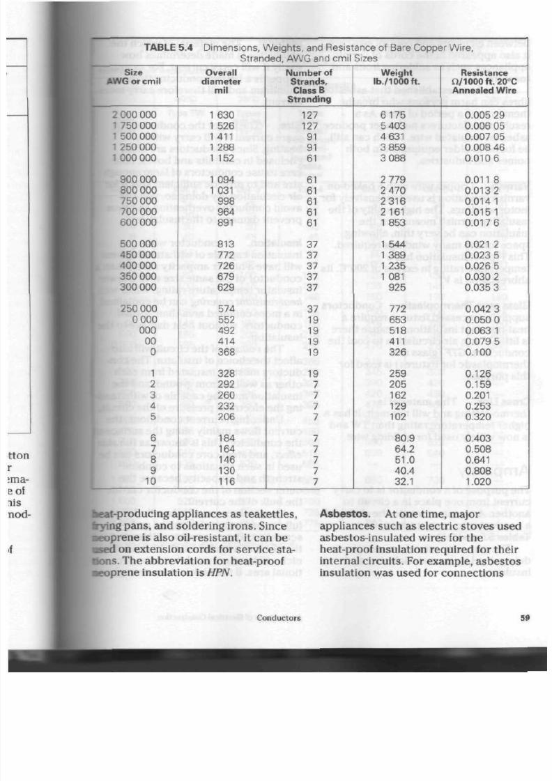
8/19/2019 Applications Electrical
http://slidepdf.com/reader/full/applications-electrical 64/447
TABLE 5.4 D ime ns ions , W eigh t s , and R es is tanc e of Bare Coppe
Size
AWG or cmil
2 000 000
1
750 000
1
500 000
1 2 5 0 0 0 0
1 000 000
900 000
800 000
750 000
700 000
6 00 000
500 000
450 000
4 00 000
350 000
300 000
250 000
0 000
000
0 0
0
1
2
3
4
5
6
7
8
9
10
St ran
Overall
diameter
mil
1 6 30
1 526
1 411
1 288
1 152
1 094
1 031
9 9 8
96 4
891
813
772
726
6 79
6 29
574
552
492
414
36 8
328
292
26 0
232
206
184
164
146
130
116
ded, A W G a n d c m i l
Number of
Strands,
Class B
Stranding
127
127
91
91
61
61
61
61
61
61
37
37
37
37
37
37
19
19
19
19
19
7
7
7
7
7
7
7
7
7
Sizes
Weight
lb /100 0 f t .
6175
5 403
4 631
3 859
3 088
2 779
2 470
2 3 1 6
2 161
1853
1 544
1 389
1 235
1 081
925
772
653
518
411
326
259
205
162
129
102
80. 9
64.2
51. 0
40. 4
32.1
r W i re ,
Resistance
fi/1000ft.20°C
Annealed W ire
0.005
29
0.006
05
0.007
05
0.008 46
0.010 6
0.011
8
0.013 2
0.014 1
0.015 1
0.017 6
0.021 2
0.023
5
0.026
5
0.030 2
0.035
3
0.042
3
0.050
0
0.063 1
0.079
5
0. 100
0. 126
0. 159
0.201
0.253
0.320
0.403
0.508
0.641
0.808
1.020
keat-producing
appliances as teakettles,
Irying
pans, and soldering irons. Since
•eoprene
is also oil-resistant, it can be
•sed
on extension cords for service sta
tions. The abbreviation for heat-proof
•eoprene
insulation is HPN.
Asbestos.
At one time, major
appliances such as electric stoves used
asbestos-insulated wires for the
heat-proof insulation required for their
internal circuits. For example, asbestos
insulation was used for connections
Conductors 5

8/19/2019 Applications Electrical
http://slidepdf.com/reader/full/applications-electrical 65/447
between elements and control switches.
It also appeared in the cords of certain
appliances such as soldering irons and
toasters.
It has been established that asbestos
fibres can harm persons who breathe
them in over a period of time. As a
result, manufacturers no longer produce
asbestos-insulated wire, which can still
be found in older equipment in both
homes and industries.
Varnish. Copp er wire with a baked-on
varnish insulation is used extensively for
motor windings. The high quality of the
insulating varnish me ans that the
insulation can be very thin, allowing
spa ce for the m any windings req uired.
This type of insulation has a
tem pe rat ur e rating in exce ss of 200°C. Its
abbreviation is V.
Glass over Thermoplastic.
Conductors
supplying recessed fixtures require a
heat-resistant insulation because there
is little, if any, air circu lation to cool the
conductors .
GTF
(glass an d
thermoplastic for fixtures) is used for
this purpose.
Cross Link. This ma terial is
thermo-setting
and will no t m elt. It ha s a
higher tempe rature rating than TW and
is now widely used for building wire.
Ampac i ty
The p urpo se of a con duc tor is to ca rry
cur rent from on e place in a circuit t o
another.
Ampacity
refers to the ability of
a conductor to carry current. (See
Tables 5.5 and 5.6)
The am pacity rate of a con duc tor is
determined by its material, size, and
insulation.
M aterial. The material of which the
cond uctor is made determines how
easily it will carry cur rent. For exam pl
copper is a better condu ctor than
aluminum and will therefore carry mo
current.
Size. The larger the condu ctor, the
m ore curre nt it will carry without
heating. Since conductors are often
enclose d in cond uits and b oxes, take
care to use co ndu ctors of large enoug
size and to prov ide sufficient sp ac e fo
air c irculation. By doing so , you will
avoid conductor overheating and thus
prevent da ma ge to the insulation.
Insulation. A
conductor with
insulation cap able of withstanding he
will have a higher ampacity rating tha
con du ctor of the sam e size with a low
insulator tem perature-rating. W ires w
heat-resistant covering
can b e co ntain
in a more confined area than normal
cond uctors, without heat damage to t
insulation.
The voltage of the circuit will also
affect th e cho ice of insulator. The con
ductors must be insulated from each
other as well as from ground, and the
insulation must be capable of withsta
ing th e electrical pr ess ure of the circu
Under high-current con ditions, the
cur rent flows mainly along the surface
the conductor. This is known as the s
effect, and steel-core conductors can
used in such situations to combine
strength and ampacity, because the
outer section of the conductor carries
the bulk of the current.
Conductors must be handled care
fully to prevent surface nicks and
scr atc he s. The condu ctor will heat at
the point of a surface nick, because th
nick will have reduc ed the cross-sec
tional area. If th e nick is de ep enou gh,
60
Applications of Electrical Construction

8/19/2019 Applications Electrical
http://slidepdf.com/reader/full/applications-electrical 66/447
TABLE 5.5 Allowable Ampacities for Not More Than 3 Copper Conductors
in a Raceway or Cable
1 Based on A mbient T emperature of 30°C
Allowable Ampacity
Size
AWG
MC M
Col.1
14
12
10
8
6
4
3
2
1
0
0 0
000
0 000
250
300
350
400
500
6 00
700
750
800
900
1 000
1250
1
500
1
750
2
000
60°C
TypeTW
Col.
2
15
2 0
30
4 0
55
70
8 0
100
110
125
145
165
195
215
240
26 0
280
320
3 5 5
385
400
410
435
455
4 9 5
520
545
560
75°C
Types
RW-75,
TW-75
Col.
3
15
2 0
3 0
4 5
6 5
8 5
100
115
130
150
175
200
230
255
285
310
335
380
4 2 0
46 0
475
490
520
545
590
6 25
6 50
665
8 5 - 9 0 C
Types
R-90,
RW-90,
T-90 Nylon,
Mineral-
insulated
cable.
Paper
Col.
4
15
2 0
30
4 5
6 5
8 5
105
120
140
155
185
2 1 0
235
26 5
295
325
345
395
4 5 5
4 9 0
500
515
555
585
6 45
700
735
775
110°C
Col.
5
3 0
3 5
4 5
6 0
8 0
105
120
135
160
190
215
245
275
3 1 5
345
390
4 2 0
4 7 0
5 2 5
56 0
580
6 00
—
6 80
—
785
—
840
125°C
Col.
6
3 0
4 0
50
65
8 5
115
130
145
170
200
240
26 5
3 1 0
3 3 5
380
4 2 0
4 5 0
500
545
6 00
6 2 0
6 40
—
730
—
—
—
—
200°C
Col.
7
3 0
4 0
5 5
7 0
9 5
120
145
165
190
225
250
285
340
—
—
—
—
—
—
—
—
—
—
—
—
—
—
—
W information of condit ions that may change the values in
.table, see the corresponding table in the Canadian Electrical
Based on Canadian Electrical Cod
Conductors
6

8/19/2019 Applications Electrical
http://slidepdf.com/reader/full/applications-electrical 67/447

8/19/2019 Applications Electrical
http://slidepdf.com/reader/full/applications-electrical 68/447
•Ere
may be
serious heat damage
to the
•rounding insulation.
Electrical Resistance
Barrent does
not
flow through
a
conduc
tor by itself. Electrical pre ssu re (volt
age) must
be
applied
to
force
the
current
n g the conductor. There is always
form
of
resistance
to
cur ren t flow
the conductor. This resistan ce
is
sured
in
ohms.
Resistance
is
determined by
the con-
tor's diameter, length, tem peratu re,
i material.
The
smaller
the
diameter,
1
longer the length, and the higher the
anperature,
the
greater
the
resistance
b f l b e .
Resistance
has
little,
if
any, effect
on
lectrical performance
in the
average
sidential
circuit. In
tall
buildings,
•pawling industrial com plexes,
or
street lighting, wh ere cond ucto rs must
fravel long distan ces , however, resist
ance is an important factor. Considera
ble voltage
may be
lost
in
delivering
the
|narrent
to the end of the
circuit.
The
result is dimming lights
and
less efficient
dectrical m otors. Voltage drop
is
reduced by increasing
the
diameter
of
Ibe wire used
in the
circuit. Tables
5.3
and 5.4 provide a comparison of the vari
ous resistances
for
solid
and
stranded
wires.
F o r R e v i e w
1. What two m aterials are most com
monly used
for
electrical conduc
tors? Why?
2. Define oxidation,
and
describe
its
effect
on
metal conductors.
3. Describe
the
process
for
produc
ing wire.
4.
Why are
cables
and
cords made
from many strands
of
wire?
5. What is the name of the gauge
used
to
measure solid co nduc
tors? W hat sizes of wire can this
gauge measure?
6. What m ethod
is
used
to
measure
the size
of
large cables?
7. A cable consists
of
19 stra nd s.
Each strand has a metric diameter
of 2.388 mm . What
is the
gauge
number of the cable?
8. A cable cons ists
of
37 stran ds,
each having a diameter of 80.8 mil
What
is the
gauge numb er
of the
individual strand? Calculate
the
nominal size
of the
cable
itself.
9. List five
or
more m aterials com
monly used
for
insulating condu c
tors.
10. Define ampacity, and list and
explain
the
factors that affect
it.
11. Why should circuit voltage be con
sidered when selecting
a
conduc
tor?
12. Explain why cu ts
or
other damage
to conductors should
be
avoided
during installation.
13. List
and
explain
the
factors tha t de
termine
a
conductor 's resistance.
14.
What
is the
effect
of
conductor
resistance on circuit voltage? Give
examples.
15. Calculate the resistance of 152 m
of
N o.
14 AWG solid bare co pper
wire.
Conductors 6

8/19/2019 Applications Electrical
http://slidepdf.com/reader/full/applications-electrical 69/447
A
ny electrical device that is designed
to rec eive its electrical supp ly from
a receptacle will be fitted with a line
cord. Cord fittings attached to the line
cord are used as a convenient m ethod
for connecting the d evice to the power
source.
Male and Female Plug Caps
Th ere are two m ain type s of cord fit
tings, or plug caps: male and female.
Both are produced with the same blade
shap es, as described in Chapter
4.
(See
Fig. 4.2)
The
male
plug cap is designed to be
inserted in to the slots of a receptacle.
(See Fig. 6.1) It is usually a tta ch ed to the
end of line cord s on elec trical appli
ances, lamps, and pow er tools.
U
o
•a
E
to
Cord
Fittings
FIGURE 6.2
body)
Female plug cap (connector
FIGURE
6.1
Ma le plug cap
The
female
plug cap is designed to
receive th e m ale plug cap. (See Fig. 6.2)
It
is attac hed to one end of an extension
cord, which has a male plug cap on the
other end. Usually, both have the same
blade shape.
Uses for Heavy-Duty Cord
Caps
Mobile hom es (trailers), electric stov es
and clothes drie rs require heavy-duty
cord caps for their power supply. In
industry, cord fittings with current and
voltage ratings other than the usual
10
to 15 A, 120 V residential ratings are
often required. Some examples are cord
ca ps for welding ma chin es, floor finishe
battery chargers, and marine shore line
64
Applications of Electrical Construction

8/19/2019 Applications Electrical
http://slidepdf.com/reader/full/applications-electrical 70/447
g Cap C onnection
Plug caps are often damaged by care
lessness. For example, many people
emove plugs from rece ptac les by tug-
0og on co rds . Figure 6.3 show s how line
sords
and plug caps are connected so
hat
the strain from pulling on the c ord
•til
be absorbed by the blades rather
ban by the ter min als. To preve nt loose
strands of the flexible cord from slipping
out of the terminal connection, the
strands are twisted together and then
sound clockwise around the terminal
screw. Soldering the g rou ps of twisted
strands before assem bly also helps
Bake the electrical connection secure.
3
Wi r e "U" Gr ound
Plug Cap
DTE Solder all
randed
wire and
•>d clockwise
ound
terminals.
neutral wire
(white)
silver
termina
ground wire (green)
green terminal
ve
wire
(black)
brass terminal
K3URE6.3
:ap
Me thod for connecting cord to
An
underwriter's
knot used to be tied
n the cord to prevent t he cord from being
pulled out of the cord cap . But stre ss
• as
placed on the cord's insulation. As a
result, a knot is seldom used with m od
em plug cap s in which conducto r space
is
limited. Instead, ind ustrial or heavy-
duty plug caps are now equipped with
metal
or plastic
clamping devices
to hold
the co rds in th e plug c ap s. (See Fig. 6.4)
These devices are particularly useful on
construction sites , where extension
x>rds and cap s are w alked on, driven
over, and trea ted roughly.
cord c lamp
plug cap
cord
pr ongs
FIGURE 6.4 Industrial (heavy-duty) plug cap
equipped w ith cord clamp
Dead-Front Plug Caps
To promote the personal safety of porta
ble equipmen t users , th e Canadian Elec
trical Code now requires that all new
plug caps be of
dead-front
construction.
A dead-front plug cap h as pron gs and
terminals assembled as a removable
unit. (See Figs. 6.5, 6.6, and 6.7) The co rd
con nects to the rear of the unit. The
front, w hich is the expose d portion of
the plug cap , is free of term inals, con
ductors, and insulating disc.
The dead-front plug cap represents a
significant improvement over the many
older, plug cap m ode ls it is being used to
replace. On older models, the insulating
disc
of the m ale plug cap fits se par ately
over the prongs where the cord has
been connected. The disc's purpose is to
Cord Fittings
6

8/19/2019 Applications Electrical
http://slidepdf.com/reader/full/applications-electrical 71/447
FIGURE 6.5 L ight-duty, dead-front plug cap
in the
" U "
ground configuration, black neo-
prene body
preven t loose stran ds or termina ls from
coming in contac t with the cover plate
the receptacle. But if the cover plate is
made of metal and no insulating disc is
prese nt, a short-circuit flash can occ ur
as the plug is inserted in to the recepta
cle. The hand of the person plugging in
the cap may be burned .
The safer dead-front plug caps are
pro du ced in all cord c ap configuration
and in both residential and industrial
grades.
Room y wi r ing c ham ber pr o
v ides ample space for wir ing .
Ribbed nylon housing of fers
secure, non-slip hand
ho ld.
W ir ing entrance holes are
angled to permit "s t raight
conductor insert ion.
Broad gr ipping area accommo
dates wide range of cable
diameters.
Grip is an integral part of
mo ulded device. Jaws of fset
cable slight ly to prevent slip
page of inner wires.
Dead front
el iminates need
Each indiv idual wir ing
|
insula t ing disc,
terminal is
completely
enclosed in its own
separate cham ber. C lear polyca rbona te perm
visual inspect ion of termi
af ter wir ing.
FIGURE 6.6 Internal construction of a heavy-duty, dead-front cord cap show ing cord and
terminal connections
66
Applications of Electrical Construction
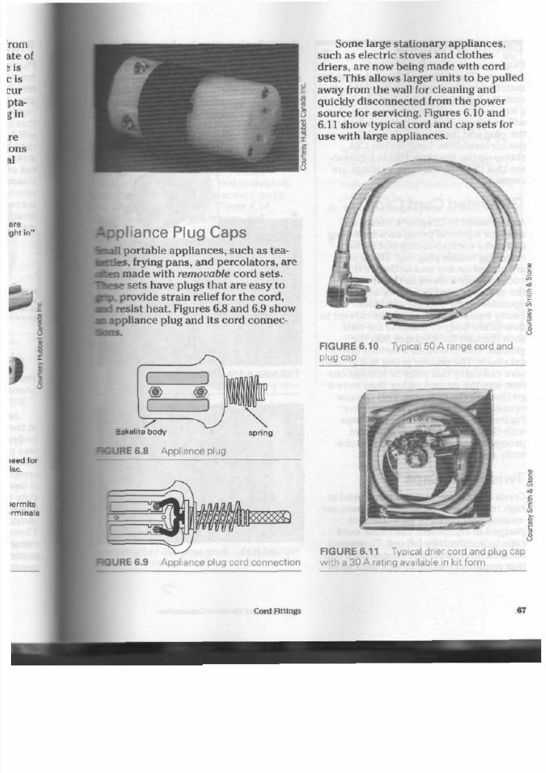
8/19/2019 Applications Electrical
http://slidepdf.com/reader/full/applications-electrical 72/447
• p l i a n c e
P lug Caps
Jl
portable appliances, such as tea-
ttles,
frying pans, and percolators, are
i
made with removable cord sets.
e sets have plugs that are easy to
provide strain relief for the cord,
I resist heat. Figures 6.8 and 6.9 show
a
appliance plug and its cord co nnec-
ttons.
s
Bakelite
body
BGURE 6.8 A ppliance plug
spr ing
Some large stationary appliances,
such a s electric stoves and clothes
driers ,
are now being made with cord
sets . This allows larger units to be pulle
away from the wall for cleaning and
quickly disconnected from the power
sou rce for servicing . Figures 6.10 an d
6.11
show typical cord and c ap se ts for
use with large appliances.
FIGURE 6.10
plug cap
Typical 50 A range cord and
C UR E 6.9 A ppliance plug cord connection
FIGURE 6.11 Typical drier cord and plug ca
with a 30 A rating available in kit form
Cord Fittings
6
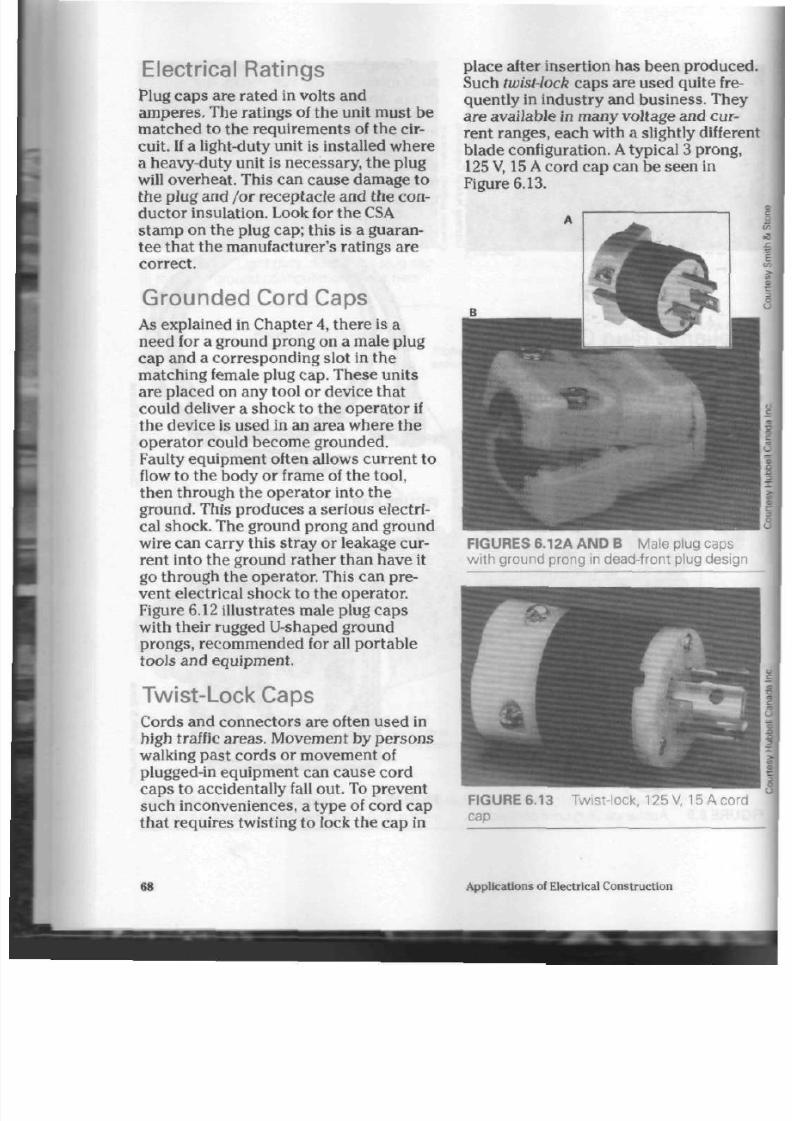
8/19/2019 Applications Electrical
http://slidepdf.com/reader/full/applications-electrical 73/447
Electrical Ratings
Plug caps a re rated in volts and
am pere s. The rat ings of th e unit must be
matched to the requirements of the cir
cuit. If a light-duty un it is installed w here
a heavy-duty unit is necessary , the plug
will ove rheat. This can c ause dam age to
th e plug and /or recep tacle and the con
du cto r insulation. Look for th e CSA
stam p on the plug cap ; this is a guaran
tee that the manufacturer 's ratings are
correct.
Grounded Cord Caps
As explained in Chapter 4, there is a
need for a ground prong on a male plug
cap and a correspo ndin g slot in the
ma tching female plug cap. These units
are placed on any tool or device th at
could deliver a shock to the operator if
th e device is used in an area where th e
operator could become grounded.
Faulty equ ipme nt often allows cu rrent to
flow to th e b ody o r frame of the tool,
then through the ope rator into the
ground. This prod uces a serious electr i
cal shock. The ground p rong and g round
wire can carry this stray or leakage cur
rent into the ground ra the r than have it
go through the operator. This can pre
vent electrical shock to the operator.
Figure 6.12 illustra tes male plug c ap s
with their rugged U-shaped ground
prongs, recommended for all portable
tools and equipme nt.
T wist-L ock C aps
Cords and conn ecto rs are often used in
high traffic are as. Movement by p erso ns
walking past c ord s or mov eme nt of
plugged-in equipmen t can cause cord
caps to accidentally fall out. To prevent
such inconveniences, a type of cord cap
tha t requ ires twisting to lock th e cap in
place after insertion has been produced
Such twist-lock caps are used quite fre
quently in industry and business. They
are available in many voltage and cur
ren t ran ge s, eac h with a slightly differen
blad e configuration. A typical 3 prong,
125 V, 15 A cord cap can be seen in
Figure 6.13.
FIGURES
6.12A
A N D B
Male plug
caps
w ith ground prong in dead-front plug design
FIGURE 6.13 T wist-lock, 125 V, 15 A cord
cap
68
Applications of Electrical Construction

8/19/2019 Applications Electrical
http://slidepdf.com/reader/full/applications-electrical 74/447
>spital Grade C ord C aps
pital grade cord cap s are designed to
the most demanding needs of hos-
and health care facilities. Their
n bodies resist imp act, grea se, oil,
abrasion and ultraviolet radiation,
the cord grip action reduces strain
ring terminals and helps prevent
ightening of assem bly screw s.
-coded faces are clearly marked
amp erage and voltage ratings
—blue, 20 A— red), and individual
nnelled wire wells acc ept up to
) AWG con du cto rs. Figure 6.14
ates hospital grade caps and
tors .
F o r R e v i e w
1. Describe th e two m ain types of
cord fittings.
2. List five common cord cap blade
shapes.
3.
What may happen if a plug is
removed from a receptacle by pul
ling on the cord?
4. Why are the co ndu ctors taken
around the blade of the plug cap
before securing them to the termi
nal screw?
5. What is the purpose of soldering
the cord strands before winding
them around the terminal screw?
6. Why are heavy-duty plug caps
equippe d w ith clamping dev ices
for the co rds?
7. Describe the insulating disc, and
explain its purpose.
8. What is the p urpo se of th e dead -
front plug cap?
9. List two rea son s why large appli
ance s are being fitted with cord
sets.
10.
List the electrical ratings that
must be marked on plug caps.
JRE6.14 Hosp ital grade nylon plugs
I connectors
Cord Fittings
6

8/19/2019 Applications Electrical
http://slidepdf.com/reader/full/applications-electrical 75/447
M
ode rn wiring system s require an
electrical outlet box at each point
in th e circuit whe re a switch, lamp-
holder, rece ptacle, or splice is loca ted.
Section
12
of the C anadian Electrical
Code provide s an up-to-date sum ma ry of
installation procedures.
Most electrical boxe s are mad e
of
galvanized or cadmium -plated steel.
Nonmetallic wiring systems may use
boxes m ade of
Bakelite.
This heat-resist
ant material cannot be used for metallic
wiring syste m s be ca us e it is quite fragile
and n ot able to withstand th e strain of
metal box connectors.
W here there is mu ch m oisture, boxes
may be m ade of
brass
or
everdur.
These
nonrusting, high-corrosion-resistant
ma terials prevent box damage from
chemicals or moisture in the surround
ing air.
There are several types of boxes for
various uses: the octagon, pancake,
square, sectional plaster, utility, and con
crete-masonry-tile.
Octagon Box
This typ e of box usually supports light
fixtures or serves as
a junction
point for
wire splice s. It can also be use d with
special covers as a supp orting box for a
switch or receptacle.
Electrical
Outlet
Boxes
Dimensions. Octagon boxes are
available in two diam eters. The 10 cm
diameter box is the most common.
Boxes with d iam eters from 8 cm to 9 c
are available for applications where th
box size is limited . (See Fig. 7.1)
10 c
w id e
x 4
dee
FIGURE 7.1 T ypical octagon box
FIGURE 7.2 O ctagon box extensions
70
Applications of Electrical Construction

8/19/2019 Applications Electrical
http://slidepdf.com/reader/full/applications-electrical 76/447
Note: Check the Canadian Electrical
Code requ irem ents for your area .
Another important box dimension is
depth. This measurement determines
tbe amount of conductor space within
the box. The m ost comm on d epth is
4 cm.
A
box 5.5 cm in de pt h is available
br installation where m ore con duc tor
space is required.
Box extensions are designed to
mo unt directly on th e to p of an ex isting
octago n box. They are simply octag on
boxes without bottom s to provide an
increase in con ducto r spac e when
required. (See Fig. 7.2)
Covers. The re are many type s of
octagon box cove rs, allowing the box to
ser ve many pu rp os es . (See Fig. 7.3) Box
cov ers and extension boxes are fastened
with two
No.
8-32 round-head machine
screw s, which are provided with eac h
box.
Octagon Concrete R ings. Th ese rings
are used in buildings wh ere the bo xes
and wiring system are installed before
th e c on cre te is poure d. (See Fig. 7.4)
They are available in d ep ths of 4 cm t o
15 cm. There can be a cover on either
end of th e ring. Figure 7.5 show s a
con crete ring installation.
FIGURE 7.4 Typical 10 cm octagon con
crete ring (C over screw may be wax-pro
tected.)
CURE 7.3 O ctagon box covers
Knockouts.
Knocko uts, or
KOs,
are
removable and provide for the entrance
of wire, cable, or conduit to the box.
Described in App endix
G
of th e
Canadian E lectrical Code, they are m ade
in comm on trad e sizes, for examp le,
13 mm, 20 mm , or 25 mm. A 13 mm
knockout is designed to accept a condui
with an internal diam eter of 13 mm . The
Electrical Outlet Boxes
7
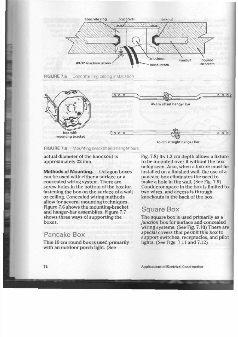
8/19/2019 Applications Electrical
http://slidepdf.com/reader/full/applications-electrical 77/447
concrete r ing box cover locknut
#8-32 machine screw
conduit poured
conductors concrete
FIGURE 7.5 Concrete ring ceiling installation
45 cm offset hanger
bar
box with
mounting bracket
FIGURE 7.6 Mounting bracket and hanger bars
D o 6 6
o
o
45
cm
straight hanger
bar
actual diameter of the knockout is
approximately 22 mm.
Methods of Mounting.
Octagon boxes
can be used with either a surface or
a
concealed wiring system . There are
screw ho les in the bottom of th e box for
fastening the box on the surface of a wall
or ceiling. Concealed wiring m ethods
allow for severa l mounting techn iques.
Figure 7.6 shows the mounting-bracket
and hanger-bar assem blies. Figure 7.7
shows three ways of supporting the
boxes.
Pancake
Box
This 10 cm round box is used primarily
with an ou tdoor porch light. (See
Fig. 7.8) Its 1.3 cm depth allows a fixtu
to be mounted over it without the box
being seen. Also, when a fixture must b
installed on a finished wall, the use
of
a
pancake box eliminates the need to
make a hole in the wall. (See
Fig.
7.9)
Conductor spac e in the box is limited t
two wires, and access is through
knockouts in the back of the box.
Square Box
The square box is used primarily as
a
junction
box for surface and concealed
wiring system s. (See Fig. 7.10) There ar
special covers that perm it this box to
support switches, receptacles, and pilo
lights. (See Figs. 7.11 and 7.12)
72
Applications of Electrical Construction
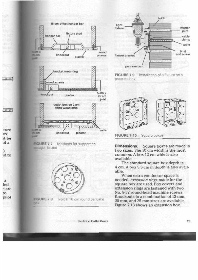
8/19/2019 Applications Electrical
http://slidepdf.com/reader/full/applications-electrical 78/447
45 cm offset hanger bar
knockout
plaster
knockout
plaster
~
i
outlet box on 2 cm
thick wood strip
v x
:• > \ w
-£zZ>
.jH >V\'.iW\
knockout plaster
nails
CURE 7.7 Me thod s for suppo rting
Bagon boxes
BGURE 7.8 Typical 10 cm round pancake
Electrical Outlet Boxes
l ight
f ixture morta
jo int
f ixture bracket
p lug
and scre
pancake box
FIGURE 7. 9
Installation of a fixture on a
pancake box
FIGURE 7. 10
S quare boxes
Dimensions. Square boxes are ma de i
two sizes. The
10
cm width is the m ost
common. A box 12 cm w ide is also
available.
The standard square box depth is
4 cm.
A
box 5.5 cm in d ep th is also avail
able.
When extra conductor space is
needed, extension rings ma de for t he
squ are box are used . Box cove rs and
extension rings are fastened with two
No.
8-32 round-head machine screws.
Knockouts in a combination of
13
mm,
20 mm, and 25 mm sizes are available.
Figure 7.13 show s an e xtension box.
7

8/19/2019 Applications Electrical
http://slidepdf.com/reader/full/applications-electrical 79/447

8/19/2019 Applications Electrical
http://slidepdf.com/reader/full/applications-electrical 80/447
The Canadian Electrical Code
luires
that th e front of the box b e
h with the surface of walls finished in
lbustible
materials, such as wood
Belling. (This is a precautio n to pre-
a flash fire in the box from spread -
[to the surrounding m aterial.) The
:
may be reces sed up to 6 mm in walls
[plaster or m asonry.
Construction.
Most sectiona l plaster
nxes are ma de of galvanized steel,
kelite,
or phenolic, boxes are available
use with nonmetallic wiring system s.
The sides of the metal boxes are eas-
removed for
grouping,
or ganging
ler,
a series of b oxe s. (See
7.15) This feature allows an installer
mt
quickly assem ble a box capa ble of
••pporting any num ber of switche s or
eceptacles. Sectional boxes m ade by
e man ufacturer may not link up with
hose mad e by another. When assem -
fcg
a gang unit, therefore, take care t o
elect boxes of the sam e type.
• • t e n s i o n s . The stand ard sectional
i
is 5 cm w ide and 7.5 cm in heigh t.
i de pth of the box varies with th e
nt of cond uctor spa ce
required,
stand ard dep th is 6.5 cm. Units
7.5 cm, 5 cm, and 4 cm in dep th are also
available.
Co vers. Covers for this box are m ade
primarily for switches or receptacles. A
blank
co ver is used w hen th e box is to
serve as a junction point for splices
in the w ires.
Plaster
boxes have two
No.
6-32 thread ed mou nting lugs
space d 8 cm apa rt, which accep t any
manufacturer's switch or receptacle.
The covers are usually fastened to the
switch or recep tacle with
N o.
6-32
machine screws. (See Fig. 7.16)
FIGURE 7.16 S ectional plaster box covers
O
Ml ' lt§l
o
IRE 7.15
Sectional plaster boxes for ganging
Electrical Outlet Boxes
7

8/19/2019 Applications Electrical
http://slidepdf.com/reader/full/applications-electrical 81/447
Gang cove rs are used for m ultiple
switch or receptacle units mo unted in
grouped boxe s. Sectional boxes a re
som etime s used to enclose pilot lights,
which indicate wh en a piece of electrical
equipm ent is operating. Covers for this
pu rpo se are also available.
Bakelite, or phe nolic, is usually used
in the m anufacture of cove rs.
It
is a good
insulator, heat-resistant, easily moulded,
and generally low in cost, making it ideal
for th e pu rpo se. B rass, aluminum, stain
less steel, and galvanized steel covers
are produced w here a stronger or m ore
decorative cover is needed.
Method s of M ounting.
Sectional
plaster boxes can be suppo rted in
severa l way s. Figure
7.17
show s a group
of boxes equipp ed with m ounting
bra ck ets. Figure 7.18 shows ho w single
or ganged units can be supported.
W hen a bo x mu st b e installed in a fin
ished wall, a special purpose unit can be
used . This sectional box is equipp ed
with an expanding bracke t that will pa ss
throu gh a pre-cut hole in the wall,
expand , and grip the plaster when a ten
sion bolt is tightened. The cab le mu st be
fastened securely to the box before the
box is inserted into the ho le. Once the
bracket has expanded, it cannot be
rem ove d easily. (See Fig. 7.19, page 78.)
A second me thod of mounting sec
tional boxes in existing walls depends on
the use of the recently developed swing
arm.
After c utting a hole in th e wall to .
accep t th e new box, the installer con
nects the cable to a built-in cable clamp
in the usual m anner and inserts the box
into plac e in th e wall.
Plaster ears
pre
vent the box from falling through the
hole, while adjustm ent of a spec ial screw
brings th e swing arm into a holding posi
tion on th e inside of the
wall.
Further
use of the special screw tighten s the
o
0
\ °
•*•
0
O
slfcP
J o
IISII
RT^s^,
0
0 °
c0°
FIGURE 7.17 S ectional plaster boxes wit
mounting brackets
76
Applications ol Electrical Construction
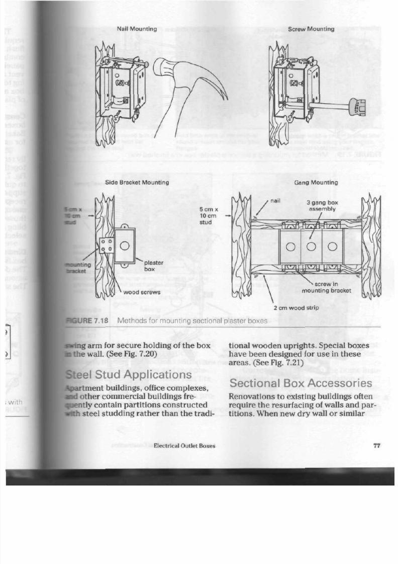
8/19/2019 Applications Electrical
http://slidepdf.com/reader/full/applications-electrical 82/447
Na i l Mo u n t in g
Scre w Mo u n t in g
Side Bracket Mounting
H
Gang Mount ing
plaster
box
wood screws
5cmx
10 cm
stud
2 cm w o o d s t r ip
CURE 7.18 Methods for mounting sectional plaster boxes
ing arm for secure holding
of
the box
the wall. (See Fig. 7.20)
•teel S tud A ppl icat ions
tment
buildings, office complexes,
othe r comm ercial buildings
fre-
ently
contain parti t ions constructed
lith steel studding rather than the tradi
tional wooden uprigh ts. Special boxes
have been designed for u se in these
areas. (See Fig. 7.21)
S ectional Box A ccessories
Renovations
to
existing buildings often
require the resurfacing of walls and par
tition s. When new dry wall or similar
Electrical Outlet Boxes
77
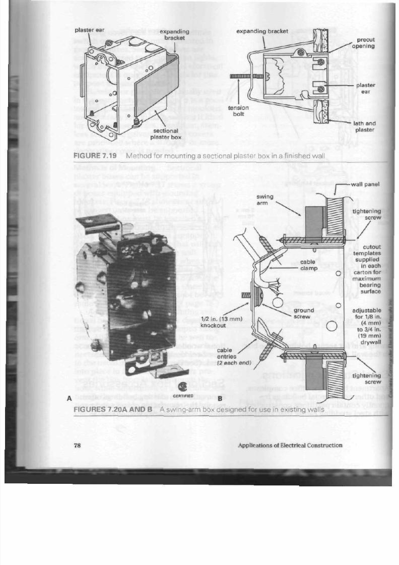
8/19/2019 Applications Electrical
http://slidepdf.com/reader/full/applications-electrical 83/447
plaster
ear
expanding
bracket
expanding bracket
sect ional
plaster
box
t ens ion
bolt
precut
opening
plaster
ear
lath and
plaster
FIGURE 7.19 Me thod for mo unting a sectional plaster box in a finished wall
s wing
arm
1/2 in .
(13
m m )
knockout
cable
entries
(2 each end)
wall panel
t igh t en ing
screw
cutou
templates
suppl ied
in each
carton fo
m a x i m u m
bear ing
surface
adjustable
for 1/8 in
(4 mm
to 3/4 in
(19 mm
dr y wal
t ightening
screw
yy CERTIFrEO „
FIGURES
7.20A
A N D B A swing-arm box designed for use in existing walls
78
Applicat ions of Electr ical Construct ion
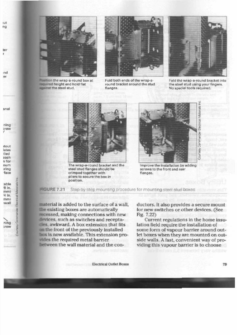
8/19/2019 Applications Electrical
http://slidepdf.com/reader/full/applications-electrical 84/447
I
the wrap-a-round box at
3
height and hold f lat
•ne steel stud.
Fold both ends of the wrap -a
round bracket around the stud
flanges.
Fold the wrap-a -round bracket into
the steel stud using your f ingers.
No special tools required.
u
-
-"
a
-
-
~
y
—
z
-
•
-
t
0
u
-
3
The wrap-around bracket and the
steel stud f langes should be
cr impe d together w ith
pliers to secure the box in
posit ion.
Improv e the insta l la t ion by adding
screws to the fron t and rear
f langes.
GURE 7.21 S tep-by-step mounting procedure for mounting steel stud boxes
aterial is added to the surface of a wall,
le
existing boxes are automatically
scessed, making conne ctions with new
evices, such as switches and recepta-
les.
awkw ard. A box exten sion th at fits
a
the front of th e previous ly installed
OK
is now available. This extension pro-
Ides the required m etal barrier
etween
the wall material and the con
du cto rs. It also provides a secure mo unt
for new switches or other devices. (See
Fig. 7.22)
Current regulations in the hom e insu
lation field require the installation of
som e form of vap our ba rrier around out
let boxes when they are m ounted on out
side walls. A fast, convenient way of pro
viding this vapour barrier is to ch oo se
Electrical Outlet Boxes
7

8/19/2019 Applications Electrical
http://slidepdf.com/reader/full/applications-electrical 85/447
new wal l sur face
old wall surface
S B EX
new
wall ••
surface
old wal l
surface
switch box switch bo
/'/' "i &
* " " s B E x " "
FIGURE 7.22 Installation of SBEX switch box extension wh en resurfacing old walls in existi
buildings
som ething from th e new line of tran spa r
ent, tough, resistant plastic pro duc ts
tha t will stan d u p to extrem e cold. The
plastic is moulded into single and 2 gang
box sh ap es . The larger, 2 gang units can
also be used to en close squa re or octa
gon b oxe s in the 4 in. (10 cm ) size. (See
Fig. 7.23)
Utility Boxes
This versatile box is used to support
receptacles, switches, and pilot lights in
surface wiring sys tem s. Its roun ded
corners and smooth exterior design
make it an ideal unit for surface wiring
system s with cable or condu it.
Construction. The utility box is
usually m ade of galvanized or
cadmium-plated steel. (See Fig. 7.24)
Dimensions. Standard utility box
widths vary between 5.5 cm to 6 cm
80
depen ding on the manufacturer. T he
length of the box is a stan dard 10 cm.
The d epth is usually 4 cm. A unit 5 cm
depth is available.
Covers.
Utility box cov ers are usual
ma de of plated steel. Bakelite cove rs
should not be used because the sharp
corn ers break easily whe n used with
surface wiring materials.
Most utility box cov ers a re m ade f
recep tacles and sw itches. However, p
light and blank co vers are also availab
(See Fig. 7.25)
M ethods of M ounting. There are
several units with mounting b racke ts
attached. (See Fig. 7.26) Holes are
provide d in th e back of the box for b o
or screws when the box is mounted
directly on a surface. The devices are
fastened to the box with No. 6-32
machine screws.
App lications of Electrical C onstruction

8/19/2019 Applications Electrical
http://slidepdf.com/reader/full/applications-electrical 86/447
r use with any
anx 7.5 cm
I • := box up to
For use with all two
gang device boxes
up to 7.5 cm and 10 cm
square or octagonal
boxes in either shallow
or deep configurations
Installat ion Procedure
1. Remov e the necessary pry-ou ts fro m the
metal box. Place the metal box inside the
vapour barrier. Adjust the front of the metal
box at the required distance for f lush
mo u n t in g w i th d ryw a l l .
2.
A t tach the metal box with i ts vapour
barr ier to a stud with nai ls or screws.
3. P uncture the box 's vapour barrier wi th a
square head screwdriver where the pry-
outs have been removed. Push the cable
(nonmctailic sheathed cable) through the
hole in the vapour barr ier. T hen, fo l lo w
usual wir ing procedures.
a) Unskinned cable will penetrate a box's
vapour barrier and metallic device boxes
easier than skinned cable. Cable can be
skinned after entered in the box and
pulled back to its proper length.
b) Insulation paper mus t be placed behind
the f lange of the vapour barrier so that
the front surface of the f lange will seal
effectively.
BGURE 7.23 P reshaped, plastic vapour barriers provide adequate protec tion from m oisture
:o pass through an outlet box.
5.5 cm to 6 cm
wide
10 cm long
4 cm to 5 c m
deep
I
• C U R E 7.24 Typical utility box and extension FIGURE 7.25 Utility box covers
Electrical Outlet Boxes
81

8/19/2019 Applications Electrical
http://slidepdf.com/reader/full/applications-electrical 87/447
I
a m
r^®
9>j
f
FIGURE 7.26 Utility boxes w ith mo unting
brackets
Concrete-Masonry-Ti le
Boxes
Industrial and commercial buildings
made with poured concrete or other
ma sonry m aterials require a box that
can be set directly into the material
during
construction. These boxes are
intended to be used with concealed
metallic
w iring sy ste m s. (See Fig. 7.27)
Construction. Concrete-masonry-tile
boxes are usually made of galvanized
steel.
Dimensions. A single-gang unit is 5 cm
wide and 9.5 cm in height.
It
is also
available in a multi-switch unit c apa ble
of supporting five switches or
receptacles.
Covers.
Covers are m ade for single or
group installation of switches,
receptacles, and pilot lights, or
combinations of all three.
M ethods of M ounting. These boxes
are held in place by the co ncre te o r
m ortar of the m asonry wall . When t he
© er c? cr
<s>"
o <=»
ooQoo ooQoo
o°o o°o
o"p'P p P £>
FIGURE 7.27 C oncrete-masonry-tile box
building is made with poured conc ret
walls and floors, the boxes may be w
into position to hold them securely
while th e conc rete is being po ured.
Electrical boxes provide access for co
du ctor s in two ways. The removable
disc,
called th e knockout, allows con
and/or cable connectors in trade size
13 mm, 20 mm, and 25 mm internal di
eter to be fitted to the box.
Boxes designed for use with nonm
tallic or armoured-ca ble syste m s are
available w ith
built-in clamps.
These
cable clam ps eliminate the need for s>
arate connecting de vices and also
sho rten th e time required for this
ope
tion.
The rem ovable disc designed for
boxes equ ipped w ith cable clamps is
called the
pry-out.
A ppendix G of the
Canadian Electrical Code describ es t
82
Applications of Electrical Construction

8/19/2019 Applications Electrical
http://slidepdf.com/reader/full/applications-electrical 88/447
knockout pry-out
Standard sizes are
13 m m 20 m m 25 m m
JRE
7.28 Typical knoc kout and pry-out
pry-out as "a knockout provided with a
slot in order that a screwdriver may be
inserted to pry out the knockout." (See
Fig. 7.28)
Th ere are se veral t ype s of built-in
box c on ne ctor s. (See Fig. 7.29) Built-in
cable cla m ps are usually found in octa
gon and sectional
plaster
bo xes. (See
Fig. 7.30)
standard
nonmetallic
sheath connector
o]
SI
©0
0
©
3 X
J
o
l O o
<
Q O
nonmetal l ic
sheath connector
(for use wi th 10 cm octago n
box with 4 cm depth only)
ar m our ed
cable connector
FIGURE 7.29 C able clamps
FIGURE 7.30 Boxes with built-in cable
clamps
Electrical Outlet Boxes
83
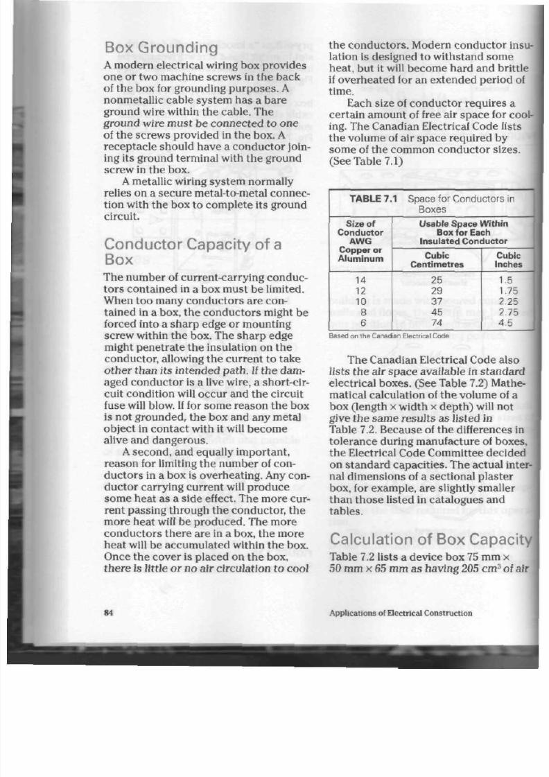
8/19/2019 Applications Electrical
http://slidepdf.com/reader/full/applications-electrical 89/447
Box Grounding
A
mod ern electrical wiring box prov ides
one or two m achine screws in the back
of the box for grounding p urp ose s. A
nonmetallic cable system has a bare
ground w ire within the c able. The
ground wire mu st be conn ected to one
of the screw s provided in the box. A
receptacle should have a conductor join
ing its ground terminal with the ground
screw in the box .
A metallic wiring system norm ally
relies on a secure metal-to-metal connec
tion with the b ox to com plete its ground
circuit.
Conductor Capacity of a
Box
The number of current-carrying conduc
tors contained in a box must be limited.
When too many conduc tors are con
tained in a box, the c on duc tors might be
forced into a sha rp edg e or m ounting
screw within the box. The sh arp edge
might penetrate the insulation on the
conductor, allowing the current to take
oth er than its intend ed path. If th e dam
aged c on du cto r is a live wire, a short-cir
cuit condition will occur and the circuit
fuse will blow. If for some reason the box
is not grounded, th e box and any metal
object in contact with it will become
alive and dangerous.
A seco nd, and equally im portan t,
reason for limiting the number of con
du cto rs in a box is overheating. Any con
ductor carrying current will produce
some heat as a side effect. The more cur
rent passing through the conductor, the
more he at will be pro du ced . The mo re
cond uctors there are in a box, the more
heat will be accum ulated within the box.
Once the cov er is placed on th e box,
the re is little or no a ir circulation to cool
the conductors. Modern conductor ins
lation is designed to withstand som e
heat, but it will become hard and brittl
if ov erhe ated for an extend ed period of
time.
Each size of cond ucto r req uires a
certain amount of free air space for co
ing. Th e C anadian E lectrical Code lists
the volume of air spa ce requ ired by
some of the common c ondu ctor s izes.
(See Table 7.1)
TA BLE 7.1 Space for C onductors in
Boxes
S ize of
C onductor
A W G
Copper or
A l u m i n u m
14
12
10
8
6
Usab le S pace W i th i n
Box
for
Each
Insu l a ted C onductor
Cubic
C ent i metres
2 5
29
37
4 5
7 4
Cubic
Inches
1.5
1.75
2.25
2.75
4.5
Based on the Canadian Electrical Code
The Canadian Electrical Code also
lists the air sp ac e available in stan da rd
electrical bo xes . (See Table 7.2) Mathe
matical calcu lation of the volu me of a
box (length x width x dep th) will not
give the s am e results a s listed in
Table 7.2. Because of the differences in
toleran ce du ring man ufacture of boxes
the E lectrical Code C omm ittee decided
on stand ard capa cities. Th e actual inte
nal dime nsions of a sectional plaster
box, for exa mp le, are slightly smaller
than th ose listed in catalogu es and
tables.
Calculation of Box C apaci
Table 7.2 lists a dev ice box 75 mm x
50 mm x 65 mm as hav ing 205 cm
3
of a
84
Applications of Electrical Construction

8/19/2019 Applications Electrical
http://slidepdf.com/reader/full/applications-electrical 90/447
Box
Dimensions
Trade Size
O c t agon
.are
r
- . - d
Mas onry Box
T A B L E 7 . 2
Mi l l imetres
100x40
1 0 0 x 5 5
1 0 0 x 4 0
1 0 0 x 5 5
1 2 0 x 4 0
120x55
100x13
75 x 50 x 40
75 x 50 x 50
75 x 50 x 55
75 x 50 x 65
75 x 50 x 75
100 x 50 x 40
1 0 0 x 5 5 x 4 0
1 0 0 x 5 5 x 4 5
1 0 0 x 5 5 x 4 8
1 0 0 x 6 0 x 4 8
95 x 50 x 65
95 x 50 x 90
100 x 55 x 60
1 0 0 x 5 5 x 8 5
N u m b e r o f C o n d u c t o r s
Cubic
C e n t i m e t r e
Capaci ty
C opper or
A l u m i n u m
245
3 4 5
345
4 9 0
490
6 9 0
82
130
165
165
205
245
145
165
2 4 5
2 3 0
2 6 0
230/gang
3 4 5 / g a n g
3 3 0 / g a n g
3 6 5 / g a n g
14
10
14
14
2 0
2 0
2 8
3
5
6
6
8
10
6
6
10
9
10
9
14
13
14
n Boxes
M a x i m u m N u m b e r o f
Ins u la ted C onduc t ors
Size in AWG
12
8
12
12
17
17
2 4
2
4
5
5
7
8
5
5
8
8
9
8
12
11
12
10
6
9
9
13
13
18
2
3
4
4
5
6
4
4
6
6
7
6
9
9
9
8
5
7
7
10
10
15
1
2
3
3
4
5
3
3
5
5
5
5
7
7
8
6
3
4
4
6
6
9
1
1
2
2
2
3
2
2
3
3
3
3
4
4
4
rings to have the same value as the eq uivalent trade size box
the Canadian Electrical Code
pace.
Table 7.1 lists a
No.
14 gauge con-
fcctor as requiring 25 cm
3
of air sp ac e,
therefore, the number of
No.
14 gauge
•ductors
allowed in this box will be :
=
8.2
ir sp ac e in the box 205
Air spa ce of 1 conductor " 25
f cours e, only 8 con du ctors can b e put
I
the box.
Clamps, receptac les, sw itches, or
?r devices inside the box take u p
ie
of the free air sp ac e. Section 12 of
| Canadian Electrical Code state s tha t
each
device in the box,
one
conduc-
• must be subtracted from th e tota l
listed (in Table 7.2). For exam ple, th e
device box listed as having a capacity of
6 condu ctors would be limited to 4 con
du cto rs, if it conta ined a switch an d
built-in ca ble c lam ps.
Section 12 of the Canadian Electrical
Code explains in detail how con duc tors
entering and/o r leaving a box must be
counted to determine the total number
of conductors allowed. Always use the
latest edition of the Code, which is
revised regularly.
Since th e C anadian Electrical Code
and much of the electrical industry
use imperial measu rem ents, imperial
Electrical Outlet Boxes

8/19/2019 Applications Electrical
http://slidepdf.com/reader/full/applications-electrical 91/447
TABLE 7 .3 Imper i a l D i m ens i on s and C onductor C apac i t i es fo r E l ec tr ica l W i r i ng Boxes
Box
Dimensions
Trade Size
O c t a g o n
S q u a r e
Round
Device
Masonry
Inches
4x172
4 x
27s
4 x 172
4 x27s
4"/ux1Vfe
4'7iex278
4x72
3 x 2 x 1 7 2
3 x 2 x 2
3 x 2 x 2 7 A
3 x 2
x
272
3 x 2 x 3
4 x 2 x 172
4 x 27s x 17
2
4x27sx1
3
/4
4 x 2 7 8 x 1
7 B
4 x 2
3
/ e x 1 7
8
3
3
/4 x 2 x 2 7
2
3
3
A x 2 x 3V
2
4 x 2 7 4 x 3 7
8
4 x 274 x 3 7
8
Cubic
Inch
Capacity
Copper or
Aluminum
15
21
2 1
3 0
3 0
42
5
8
10
10
12.5
15
9
10
15
14
16
14/gang
21 /gang
20.25 /gang
22.25 /gang
Maximum Number of
Insulated Conductors
Size in AWG
14
10
14
14
20
20
28
3
5
6
6
8
10
6
6
10
9
10
9
14
13
14
12
8
12
12
17
17
2 4
2
4
5
5
7
8
5
5
8
8
9
8
12
11
12
10
6
9
9
13
13
18
2
3
4
4
5
6
4
4
6
6
7
6
9
9
9
8
5
7
7
10
10
15
1
2
3
3
4
5
3
3
5
5
5
5
7
7
8
6
3
4
4
6
6
9
1
1
2
2
2
3
2
2
3
3
3
3
4
4
4
TABLE 7 .4
W i r i ng Boxes and The i r C onductor C apac it ies fo r Use on 347 V S ys tems
Dimensions in Inches
347 V Boxes
3x274x272
4 x 27a x 1 Ve
4 x 274 x 27a
4x274x37s
Cubic Inch
Capacity
15.7
16.5
20.25 /gang
22.25 /gang
Maximum Number of Conductors in
Boxes
Size in AWG
14
8
9
11
12
12
7
7
9
10
10
5
5
7
7
8
3
4
5
6
m easu rem ents are provided in Table 7.3.
This tab le lists electrical wiring b oxe s
and their cond uctor capacit ies .
The trend tow ard using 347 V sup
plies for lighting circuits has affected
electrical wiring box es. Switches an d
other related devices must be
somew
larger to safely handle the higher
volt-
Applications of Electrical Construction
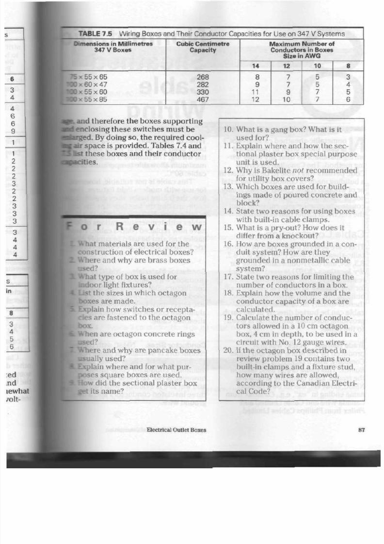
8/19/2019 Applications Electrical
http://slidepdf.com/reader/full/applications-electrical 92/447
TABLE 7.5 Wiring Boxes and Their Conductor Capacities for Use on 347 V Systems
Dimensions
in
Mi l l imet res
347 V Boxes
~: • 55x65
• 0 0 K 60 x 47
Dx 55x60
x 55
x 85
Cubic Cent imet re
Capaci ty
268
282
330
467
M a x i m u m N u m b e r
of
Conductors in Boxes
Size in A W G
14
8
9
11
12
12
7
7
9
10
10
5
5
7
7
8
3
4
5
6
s.
and therefore the boxes supporting
closing the se switches m ust
be
brged. By doing so, the required cool-
air sp ac e is provide d. Tables 7.4 and
1st these boxes and their conductor
opacit ies .
o
r
R e v i e w
t materials are used for the
construction of electrical boxes?
Where and why are brass boxes
•d ?
I type of box is used for
Indoor light fixtures?
the sizes in which o ctagon
boxes are made.
Explain how sw itches
or
recepta
cles are fastened to the octagon
box.
When are octagon concrete rings
•d ?
kliere and wh y are pancake boxes
sually used?
xplain where and for what pur-
oses square boxes are used.
low did the sectiona l plaster box
• its name?
10.
What
is a
gang box? What
is it
used for?
11. Explain where and how the sec
tional plaster box special purpose
unit is used.
12. Why
is
Bakelite
not
recommended
for utility box covers?
13.
W hich boxes are used
for
build
ings ma de of poured concrete an d
block?
14.
State two reaso ns for using bo xes
with built-in ca ble clam ps.
15. What is a pry-out? How do es it
differ from a knockout?
16. How are boxes grounded in a con
duit system ? How are they
grounded in a nonmetallic cable
system?
17. State two reaso ns
for
limiting th e
number of conductors in a box.
18. Explain how th e volume and
the
condu ctor capacity of a box are
calculated.
19.
Calculate the num ber of conduc
tors allowed in a 10 cm octagon
box, 4 cm in depth, to be used in a
circuit w ith No. 12 gauge wi res.
20.
If the o ctagon box describ ed in
review pro blem 19 contains two
built-in clamps and
a
fixture stud,
how many wires are allowed,
according to the Canadian Electri
cal Code?
Electrical Outlet Boxes
87

8/19/2019 Applications Electrical
http://slidepdf.com/reader/full/applications-electrical 93/447
N
onmetallic-sheathed
cable
(NMSC)
is used more often in residential
wiring installations than any other wir
ing method. The Canadian Electrical
Code perm its this cable to be installed in
a building made of comb ustible material
or of wooden frame construction. It may
not
be used in other types of building
construction without permission from
the electrical inspection a utho rities.
Cable Construction
There are several basic types of nonme
tallic-s hea thed cab le. (See Figs. 8.1, 8.2,
8.3,8.4,
and 8.5)
Nonmetallic
cable for
dry locations (NMD) is used in norm al
residential circuits. Nonmetallic cable
for wet locations
(NMW)
is used in farm
buildings or similar struc ture s, w here
the re is usually more mo isture. NMW
cable can be buried directly in the earth,
providing ad equ ate protec tion is given
to the cab le.
Trade N am es.
NMSC was first
produ ced by the Rom e Wire and Cable
Company, which named its new product
Romex. T his nam e is still used often in
the trade s. Each company producing
NMSC, however, has its own pro du ct
nam e ending in "ex", e.g., Canadex from
Canada Wire and Cable Limited and
Philex
from Phillips Cables Limited.
Nonmetalli
Sheathed
Cable
Wiring
Types of Insulation. NMD-3
cable
been used for several years for res
tial
wiring. The n um ber 3 indicates
maximum allowable tem pera ture of
cable : 60°C.
This cable is not suitable, howev
for use with modern light fixtures. H
from th e fixture b ulbs often drie s ou
cable, making the insulation brittle
of little value. NMD-90 and NMD-90
cables with temperature ratings of 9
have now replaced
NMD-3
cable. T
cables can a lso be used to sup ply e
tric heaters, stoves, and clothes dri
Conductor Materials.
NMSC is
produced with copper or aluminum
co nd uct ors. Since aluminum is not
good a con duc tor as copper, one w
size
larger
m ust be selected when
aluminum conductor nonmetallic-
sheathed cable.
Conductor
Sizes.
NMSC
with cop
conductors is available in gauge No
12,10, 8, 6, and 4. The sm allest gaug
aluminum conductor cable produce
how ever, is No. 12. Cable for both d
and w et use is available with two o r
three insulated conductors and a b
ground wire.
88
Applications of Electrical Construction
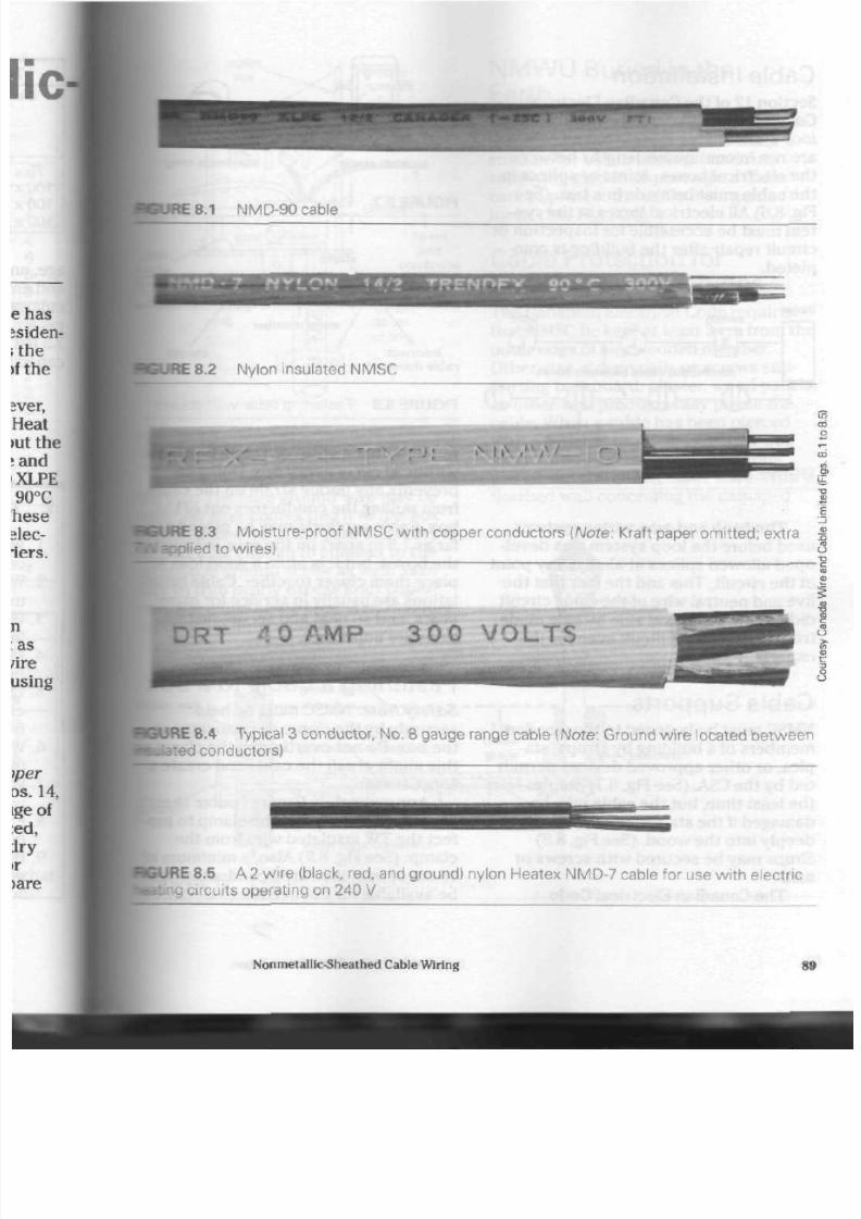
8/19/2019 Applications Electrical
http://slidepdf.com/reader/full/applications-electrical 94/447
HJRE8.1 NMD-90 cable
i 8.2 N ylon insulated N MS C
\E 8.3 Moisture-proof N MS C with copper conductors {Note: Kraft paper
omit ted;
extra
Applied to wires)
D R T -".OAMP 3 0 0 V O L T S
•BURE 8.4 T ypical 3 conductor, N o. 8 gauge range cable {Note: G round wire located betwe en
Tfeted
conductors)
CURE 8.5 A 2 wire (black, red, and ground) nylon Heatex NMD-7 cable for use with electric
circuits operating on 240 V
Nonmetallic-Sheathed Cable Wiring
89

8/19/2019 Applications Electrical
http://slidepdf.com/reader/full/applications-electrical 95/447
Cable Installation
Section 12 of the Canadian Electrical
Code requires NMSC to be installed in a
loop system. This means that all cables
are run in continuous lengths between
the electrical b oxes.
Joints.or
splices in
the cable must be made in a box. (See
Fig. 8.6) All elec trical bo xes in the sys
tem must be accessible for inspection or
circuit repair after the building is com
pleted.
panel
switch
<i>
light
,
— ®
continuous cable between boxes
receptacle
F I G U R E 8 .6 L o o p s y s t e m
The knob and tube wiring system s
used before the loop system was devel
oped allowed splices at almost any point
in th e circuit. This and th e fact tha t t he
live and n eutral w ire of the s am e circuit
did not always travel side by side m ade
troubleshooting difficult even for the
experts.
Cable Supports
NMSC mu st be fastened to th e w ood en
me mb ers of a building by straps, sta
ples, or other approved devices permit
ted by th e CSA. (See Fig. 8.7) S taples take
the least time, but th e cable m ay be
damag ed if th e staple s are driven to o
deep ly in to the w ood . (See Fig. 8.8)
Straps may be secure d w ith screws or
nails.
Th e Canadian Electrical Code
steel staple aluminu m strap
FIGURE 8.7 C able suppo rts
incorrect:
cable damaged
FIG URE 8.8 Fastening cable wi th s taple
requires that a stra p or staple be plac
within 30 cm of every box. Doing so
preve nts any undu e strain on the cab
from pulling th e con du cto rs out of the
box. Cable sup po rts m ay be placed as
far as 1.5 m apart on the ru ns between
th e b oxes , bu t it is often a good idea t
place them closer together. Cable ins
lations are usually in service for many
years, and so neat and secure installa
tions are imp ortant.
Fastening a C able to a Bo
Safety Note: NMSC must be held
securely by the clamp or conne ctor a
the box. Do not overtighten the clamp
this might crush t he cable and create
short circuit.
Approximately 6 mm of oute r
she
should extend beyond the clamp to p
tect th e TW insulated wire from the
clam p. (See Fig. 8.9) Also, a minimum
15 cm of free, insulated conduc tor m
be available for connection to devices
Applications of Electrical Co nstruction

8/19/2019 Applications Electrical
http://slidepdf.com/reader/full/applications-electrical 96/447
outlet
box
ground
screw
switch /
mo u n t in g
lug
\o
35
15
c m
free
conductor
cable strap
w i th in
30 cm
of box
KURE 8.9 Me thod for conn ecting cable to
^ ^ H b o x
fee box. Th e bare ground wire may b e
•rimmed after connecting it to the box
p o u n d screw or, in the case of a recepta
cle,
left long enoug h to co nne ct to th e
eceptacle
ground screw as well. Take
care to trim neatly exce ss kraft pap er
fcotn the cable in the box. The trimming
peduces
any fire hazard.
grade level
V
protective board
(preservative-treated)
N MW U Buried
in
the
Earth
The h eavy layer of TW insulation on th e
NMWU con du ctors makes this cable
suitable for use in underground runs
supplying garden or post lights. Take
care to protect the cable from garden
tools.
(See
Fig. 8.10)
Cable Protection for
Concealed Installations
The Canadian Electrical Code requires
tha t NMSC be kept at le ast 3 cm from the
oute r edge of any wood en mem ber.
Otherw ise, driven nails or screws su p
porting baseboa rd, plaster, wood pan els,
or other wall products may pierce the
cable. When a cable has been pierced
with a nail, the problem is usually not
discov ered until th e building is com
pleted and the circuit made alive. With a
finished wall concealing th e dam aged
T
NMWU
water-t ight connector
post l ight
concrete
15 cm sand layer
BGURE 8.10 P ost light installation using N M W U
Nonmetalllc-Sheathed Cable Wiring
9 1

8/19/2019 Applications Electrical
http://slidepdf.com/reader/full/applications-electrical 97/447
water
Ufpipe
FIGURE 8.11
tion
cable,
it is
bo th difficult and costly
to
locate and repair the fault.
Normal procedure is to drill hole s in
the centre of the wooden me mb ers that
the cable must pass thro ugh . Water and
air circulation sys tem s in the walls will
often make it nece ssary to run the cable
closer to the ed ge
of a
wooden mem ber
than the required 3 cm. In these cases, a
steel plate is
fastened
to
the wooden
mem ber in front of the cable to protect
it. Often, the plate is a side of a sectional
plaster
box left over from a gang box
assem bly. (See Fig.
8.11)
Take car e not to
damage the cable
by
locating
it
too near
to a hot-water pipe or hot-air du ct.
Residential Cable
Appl icat ions
NMSC has a maximum rating of 300 V
and will readily acce pt the 120 V/240 V
supplied to a residence.
Most circuits in house s consist of
No.
14
gauge
NMSC
and should be f
at a maximum of 15 A. Kitchen rece
cles supplying cu rrent
to
frying pa n
teakettles, or similar ap pliance s can
No.
12 gauge NMSC fused at 20 A. Th
increase in cable size and am pacity
vides a margin of safety t o a circu it
operating very close
to
its c apacity.
Home electric heating syste m s often
have circuits consisting of No.
12
ga
NMSC. Hea t-sensitive fuses sho uld b
used
to
protect th ese circuits.
Clothes driers are supplied with
cond uctor, No. 10 gauge
NMSC,
com
monly called drier cable. Fuse prote
for this cable should not exceed 30
Heat-sensitive typ e fuses are the b es
Electric stoves use a 3 conductor,
N
gauge
range cable
fused
at
35 A
to 4
depending on the size of stov e. (See
8.4,
on
page 89.)
Cable Wir ing Diagrams
An important p art of any wiring sys
is prepa ration
of a
circuit diagram. T
diagram helps determine the sequen
which the devices are
to be
connec
and the number of wires required in
cable between the boxes.
Graphical symbo ls are used to s
plify the drawing
of
electrical de vic
a circuit. Th ese universal sym bols a
listed in Appendix F of the Canadian
Electrical C ode. (See Table 8.1) Cab
are represented by a single, solid lin
with
the
number
of
insulated wires
the cable shown by short d ashes ac
th e cab le line. For example,
a 2
wire
cable is shown as ft , and a
cable
as fff
.
Remem ber that nonmetallic-
sheathed cable is available in 2 and
wire co m binatio ns. Any wiring circu
must be completed using only the w
black, or red NMSC wires a vailab le.
92
Applications of Electrical Co nstruction

8/19/2019 Applications Electrical
http://slidepdf.com/reader/full/applications-electrical 98/447
TABLE 8.1
ELECTRICAL SY MB OL S FOR ARCH ITECTURAL P LANS
z
'2
I
i
©
;;
::
:,\<
a
O
©
I
• O
-®
- C E )
-©
<£
<t>
-©
a >
- 0
-©
-©
^ , 3
~ ^ 7 W P
=©s
®
®
s
S
2
s
3
G E N E R A L O U T L E T S
Out let
Blanked O ut let
Drop Cord
E lectr ical O utlet; for use only
when c irc le used alone might
be confused with columns,
p lum b ing s y m bols , e tc .
Fan O ut let
Junct ion Box
Lam pholder
Lampholder w i t h P u l l S wi t c h
P u l l S wi t c h
Outlet for Vapour Discharge
Lam p
Exit L ight O ut let
Clock O ut let (S peci fy Voltage)
NOTE: Symbols on the left above
refer to ceilings; those on the
right above refer to walls.
RECEPTACLES
Duplex Receptacle
Other than Duplex Receptacle
1 = S ingle, 3 = T r ip lex, etc.
Spl i t -Switched Duplex Receptacle
T hr ee-Conduc t or S p l i t -Dup lex
Receptacle
T hr ee-Conduc t or
Split-Switched-Duplex
Receptacle
Weatherproof Receptacle
Range Receptacle
Switch and Receptacle
Radio and Receptacle
Special Purpose Receptacle
(Described in Specif icat ion)
Floor Receptacle
S W I T C H E S
Single Pole Switch
Double Pole Switch
T hr ee Way S wi t c h
S . Four Way S wi t c h
S D
A u t om at ic Door S wi t c h
S E E lectrol ier S witch
S K
Key O perated S witch
Sp S witch and P i lot Lamp
SC B C ircuit Breaker
SWCB
We atherproof C ircui t Breaker
S M C M om e nt ar y C ontac t S wi t c h
Sue
Rem ot e C ont r o l S wi t c h
S
W
p Weat her pr oof S wi t ch
S F Fused S witch
SWF
We atherproo f Fused S witch
S P E C I A L O U T L E T S
X
a b c
-
eic A ny standard sym bol as given above
©a.b.c.ic.
w i t n t n e
addit ion of a lower case
e subsc ript letter may be used to
^ B , b . c . e t c . t .
. . . . ,
designate some special var iat ion o f
standard equipment of par t icular
interest in a specific set of
architectural plans.
When used they must be l is ted in
the Key of Symbols on each drawing
and, i f necessary, further described
in the specif icat ions.
P A N E L S , C I R C U IT S , A N D
M I S C E L L A N E O U S
• • L igh t ing Panel
M Power Panel
— Branch C ircui t; C oncealed in
Ce i l ing or Wal l
— Branch C ircui t; C oncealed in Floor
— Branch C ircuit ; E xposed
•—••
Hom e Run to Panel Board
Indicate number of circuits by
number of arrows.
NOT E: Any circuit without further
designation indicates a two-wire
circuit. For a greater num ber of wires
indicate as follows:
-H-h
(3 wires)
-ft—If-
(4 wires), etc.
Nonmetallic-Sheathed Cable Wiring
93

8/19/2019 Applications Electrical
http://slidepdf.com/reader/full/applications-electrical 99/447
architectura l symbols
w ir in g d ia g ra ms
- # -
< D
•HZhHjHKD^KD
* * < >
- # -
4 #-
- # -
white wire used to feed switch
<XD
7
Kt>KD^-n
FIGURE 8.12 C able wiring diagrams for single-pole sw itch
Figures 8.12,8.13, and 8.14 com pa re
architectural symbols
with wiring
diagrams of basic lighting circuits. Fig
ures 8.15 and 8.16 provide more complex
circuits designed to d evelop w iring
skills. You will dev elop a gre ater und er
stan din g of th es e skills if you take tim e
94
to draw and complete the circuits on
note paper. Use coloured pencils to in
ca te th e wires . Since a cable system o
wiring requires that all splices and co
nections be in a box, it is unnecessary
show the individual conductors
betw
the boxes.
A
single line is used to
Applications of Electrical Construction

8/19/2019 Applications Electrical
http://slidepdf.com/reader/full/applications-electrical 100/447
architectura l sym bols wir in g d iagrams
< H
fe^€
-rtt-
<>*-©
< H-
<t> < D
•< tt
C)
< D
I O T E :
Receptacles alive at all t imes . S witch controls only the light.
?E 8.13 W iring diagrams w ith receptacles
present the ca ble in thes e circu its.
R
Fig. 8.12)
Figure 8.13 shows simple lighting cir-
•ts
with a duplex receptacle
added,
sceptacles are con side red to b e alive at
I
times, unless otherw ise marked on
the diagrams. Three-conductor cable is
required for some of the se circu its.
Th ree and 4 way switch-control cir
cuits are sh ow n in Figure 8.14. Three-
con duc tor cable is often used in this
typ e of circuit.
Nonmetallic-Sheathed
Cable Wiring

8/19/2019 Applications Electrical
http://slidepdf.com/reader/full/applications-electrical 101/447
architectura l symbols
w ir in g d ia g ra ms
-#/-
line
• * © •
-#-
S
3
line
-tV-
-/rV-
£>
*V— L
\—>w-
line
<—#-
-fi¥-
-¥r¥-
• ' H Z h H Z M Z h K D
S
4
S
3
FIGURE 8.14 W iring diagrams show ing 3 and 4 way switch control
96
Applications of Electrical Construction

8/19/2019 Applications Electrical
http://slidepdf.com/reader/full/applications-electrical 102/447
+-ft
7 7 ^
X - 7 ^
7 7 ^
+-6
/ / /
-7TT
7 7 7 ^
7 7 ^
JRE
8.15 Wiring diagrams using architectural symbols to show
2
and
3
w ire cables
Nonmetallic-Sheathed Cable Wiring
97

8/19/2019 Applications Electrical
http://slidepdf.com/reader/full/applications-electrical 103/447
«—
¥t
*—T¥-
W-
T 4 4 M <• V ^ - ( L V - 7 ^
PS
FIGURE 8.16 C omplex wiring diagrams using architectural symbols to show com binations o
lights,
receptacles, and assorted sw itching m ethods
98 Applications of Electrical Construction
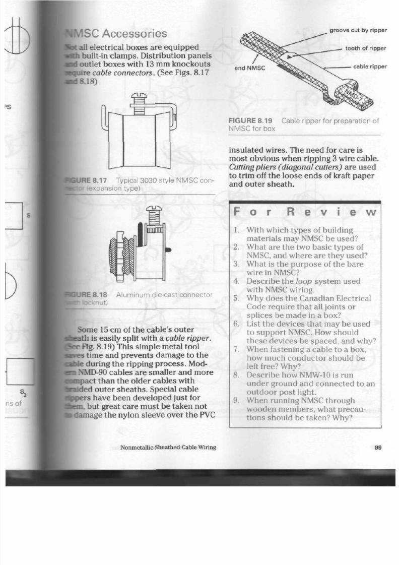
8/19/2019 Applications Electrical
http://slidepdf.com/reader/full/applications-electrical 104/447
ISC A ccessories
fat all electrical boxes are equipped
In
built-in clam ps. Distribution pan els
d
outlet boxes with 13 mm knock outs
•quire
cable connectors. (See Figs.
8.17
kd8.18)
IBURE8.17 Typical 3030 style N MS C con-
^wexpansion type)
HJRE 8.18 A luminum die-cast connector
•nut)
Some
15
cm of the cable's oute r
he ath is easily split with a cable ripper.
e Fig. 8.19) This simple metal tool
i
time and p reven ts damage to the
le
during the ripping pro ces s. Mod-
i NMD-90
cables are smaller and m ore
impact than the older cables with
aided
outer sheaths. Special cable
^pers have been developed just for
ten, but great care must be taken not
-fiage the nylon sleeve ov er th e PVC
groove cut by ripp
tooth of r ipp
cable ripp
FIGURE 8.19
NMSC for box
Cable ripper for preparation of
insulated wires. The need for care is
most obvious when ripping 3 wire cable.
Cutting pliers (diagonal
cutters)
are used
to trim off th e loos e end s of kraft pa per
and outer shea th.
F o r R e
v i e w
1. With wh ich typ es of building
materials may
NMSC
be used?
2.
What are the two basic typ es of
NMSC, and w here are they used?
3. What is the purp ose of the bare
wire in NMSC?
4.
Describe the loop system used
with NMSC wiring.
5.
Why do es the Canadian Electrical
Code require that all joints or
splices be m ade in a box?
6. List th e devic es that may be used
to su pp ort NMSC. How sh ould
these devices be spaced, and why?
7.
When fastening a cable to a box,
how much cond uctor should be
left free? Why?
8. Describe how
NMW-10
is run
under ground and connected to an
outdoor post light.
9. When running NMSC thro ug h
wooden m embers, what precau
tions should be taken? Why?
Nonmetallic-Sheathed C able Wiring
99
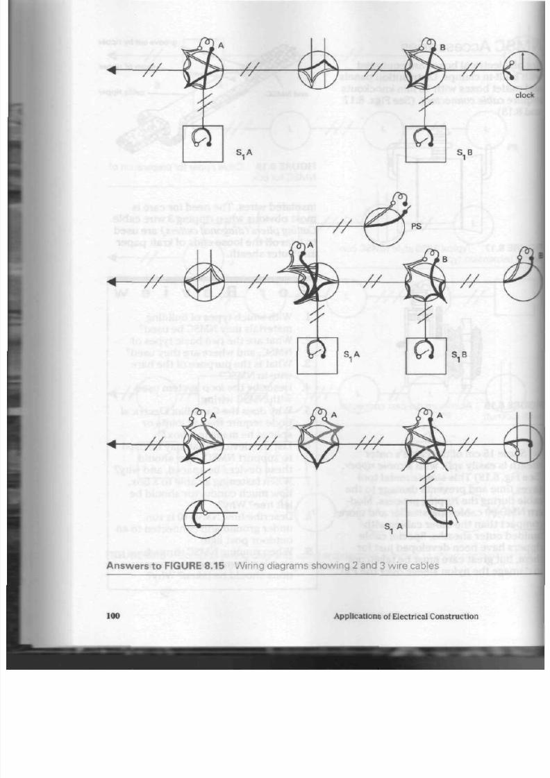
8/19/2019 Applications Electrical
http://slidepdf.com/reader/full/applications-electrical 105/447
cl
< //
JJ-
V /
• 7 4 4 ^ -
^44^
S . A
Answers to FIGURE 8.15
Wiring diagrams show ing 2 and 3 wire cables
100
Applications of Electrical Construction

8/19/2019 Applications Electrical
http://slidepdf.com/reader/full/applications-electrical 106/447
switched
receptacle
* - f r
S.A
rers to FIGURE 8.16 C omplex wiring diagrams showing combinations of lights, recepta-
, and assorted switching methods.
Nonmetallic-Sheathed Cab le Wiring
101
8/19/2019 Applications Electrical
http://slidepdf.com/reader/full/applications-electrical 107/447
T
he Canadian Electrical Code once
required that joints and splices in
insulated conductors be soldered, and
then cove red with an insulating tap e
equivalent to the insulation on the con
ductor. Soldering the splice prevented
the weakening of the electrical connec
tion by th e action of oxidation. But it
was also time-consuming and could cre
ate other problem s. When large cab les
were connected, they were heated to a
temperature that often damaged the
insulation ne ar th e sp lice. Also, to dis
connect the condu ctors, more heat was
neede d to melt the solder. The num ber
of tools required and the cost of one
time-use materials made this system
unsatisfactory. Th e need for a conven
ient method of making electrical splices
resulted in the developm ent and
subsequent
CSA
approval of so lderless
connectors.
S olderless W ire
Connectors
One of the first solderless wire connec
tors co nsisted of a tapered porcelain ca p
with an internal screw thread. While por
celain is still used in the pro duc tion of
some heat-proof units, Bakelite and/or
nylon are now most often used in the
construction of wire connectors.
Solderless
Connectors
There are three m ain types of so
less wire conne ctors: twist-on, set-
and com pression . The name s for ea
refer to the system used to apply th
unit.
Twist-on Connector. This connec
has a cone-shaped, metal spring tha
threads itself around the conductor
the co nne ctor is rotated. Several
man ufacturers pro duc e this type of
connector, but th e operating princi
th e sam e. (See Fig. 9.1) The interna
spring design takes advantage
of
leverage and vise action to multiply
strength of a perso n's han d. Th us,
conductors are forced into a solid,
effective splice. (See Fig. 9.2)
Using the twist-on c onn ector is
of the quicke st ways of splicing and
lating electrical con du cto rs. It is su
for use with solid and/or stranded
ductors operating at 600
V
or less.
models have been approved for use
1000
V.
One variety of twist-on connect
features
built-in
wings to increase t
torsion a chieved by the installer w
joining con du ctors in the
No.
12,10
8
AWG
sizes. (See Fig. 9.3)
Besides such special features, t
twist-on c onn ector is made in a ran
sizes for splicing conductors from
102
Applications of Electrical C onstruction

8/19/2019 Applications Electrical
http://slidepdf.com/reader/full/applications-electrical 108/447
••ne-retardant
isermoplastic shell
XJ|>
seated,
—r»re-wire
posit ive
grip
design
deep skirt,
wide throat
double-thick
protective cap
flame-retardant
thermoplastic shell
threaded entry
colour-
coded
square-edged
live-action
spr ing
contoured
w in g s
deep,
wide skirt
HJRE9.1 C utaway view of a twist-on
' sh owing the connec tor's internal
- d its effect on the conductors wh en
FIGURE 9.3 Wing-nut style of wire connec
tor for extra torque, or twisting
power,
while
splicing larger conductors in the No. 12 to
N o. 8 A WG range
• 3are wires and cut to length.
insulation
4
#
ends of wire
S tep 2. Insert wires an d rotate cap.
N O T E : Wires twist
together as cap is rotated
Step 3. Tighten cap fully.
N O T E :
No bare wire when cap in place
JRE 9.2 Me thod for installing a twist-on connector
Solderless Conn ectors 10

8/19/2019 Applications Electrical
http://slidepdf.com/reader/full/applications-electrical 109/447
gauge up to N o. 8 gauge. Some manufac
ture rs use a num bering system to iden
tify the different sizes of their product.
Others have adopted both number and
colour codes for easy, visual product
recognitio n. (See Fig. 9.8 on page 106)
Set-Screw Connector.
This two-piece
connector is widely used in circuits
where equipment m ust be changed
frequently for maintenance purposes.
Th e simple set-screw design allows solid
and/or stranded condu ctors to be inter
cha nge d easily. (See Figs. 9.4 and 9.5)
S tep 1. Insert wires. Do not tw ist.
FIGURE 9.4 S et-screw connector
Set-screw connectors are made for
us e on c ircuits up to 600 V, with
appro val for use on so me lighting cir
cuits of
1000
V. They are designed to
splice con duc tors from
No.
18 up to No.
10 gauge in size.
Figure 9.6 show s typical app lications
of both twist-on and set-screw connec
tors . Both are for us e in electrical boxes
or enclosures only.
Com pression Connector.
Unlike the
mechanical (set-screw) connector, this
two-piece compression connector
requires a special
crimping
(compres
sion) tool to install the cond uctor-
retaining
sleeve.
The retaining sleeves
are made of copper and/or zinc-plated
steel. An insulating cap of plastic or
nylon is fastened over th e sleeve after
set-screw
insulat ion f lush
brass connector body
S tep 2. T ighten set -screw.
threads for insulat
Be sure insulat ion
does not slip
into connector body.
D
S tep 3. Install cap.
thr
insulat
Be sure threads are
at insulat ion end of splice.
FIGURE 9.5 Me thod for installing a set
screw connector
the conductors have been crimped
firmly. (See Fig. 9.7) This typ e is for
permanent installation, because the
ductor cannot be easily removed fro
the retaining sleeve.
Th ese un its are m ade for use on
cuits of 600
V
and may be used on l
ing fixtures up to 1000 V. The retain
sleeves are made for splicing condu
No.
18 up to N o. 6 gauge . The zinc-p
steel sleeves can be used only on co
con duc tors, due to the possibility
o
electrolysis acting on the se sleev es.
Some compression con nectors a
104
Applications of Electrical Con struction
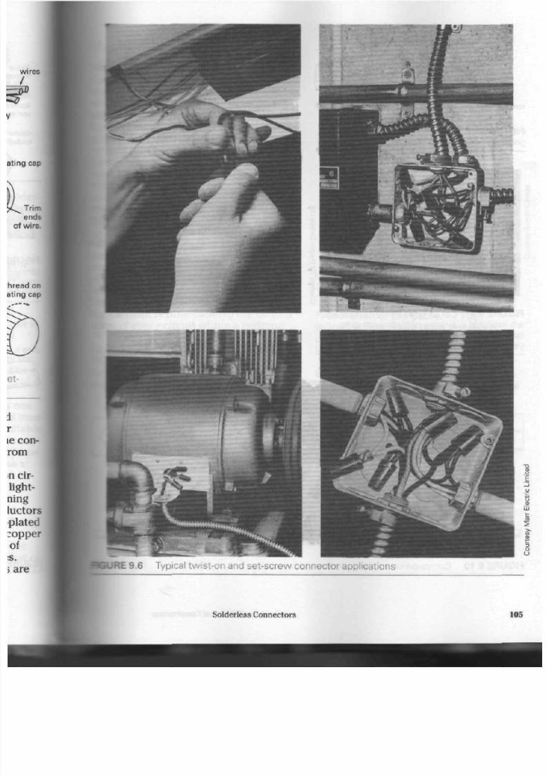
8/19/2019 Applications Electrical
http://slidepdf.com/reader/full/applications-electrical 110/447
9.6 Typical tw ist-on and set-scre w connec tor applications
Solderless Con nectors 10

8/19/2019 Applications Electrical
http://slidepdf.com/reader/full/applications-electrical 111/447
conductor retaining sleeve
indented cr imp insulat ing cap
FIGURE 9.7 Me thod for installing a com
pression connector
used to simplify the connection of
stranded conductors to a terminal
screw. These units prevent loose stra
from slipping out from und er th e term
nal screw and reducing the current-ca
rying capacity of the connection. (See
Figs. 9.9 an d 9.10) Special crimping
p
are needed to install thes e conn ector
on con du cto rs ranging from No. 18 to
No. 10 gauge.
FIGURE
9.8 C olour-coded w ire connectors
are available in a range of sizes from grey
(small) to blue and orange (medium) and to
yello w and red (large).
fork-tongue
insulated ring-tongue
FIGURE 9.9 Fork-tongue and insulated
tongue compression lug installations
FIGURE 9.10 C ompression tool and cnmp-on terminal lugs
106
Applications of Electrical Construction

8/19/2019 Applications Electrical
http://slidepdf.com/reader/full/applications-electrical 112/447
:hanical C able
nnectors
:ting cab les p os es se vera l difficul-
: all stran ds m ust be held secu rely
hout damage to any, beca use damage
I
reduce the connection's conductiv-
e connection must maintain a firm
i
on the cable, com pressing the
Js
into a solid g roup th at will not
.
after a time; and t he con nec tor
be m ade of a me tal that will not
rage electrolysis betw een itself
the cable. Mechanical connectors,
, lugs, meet these requirements.
I Fig. 9.11)
There are several kinds of mech ani
zable connectors (see Figs.
9.12,9.13,
19.14), and service entranc e equip-
: for buildings mak es extensive us e
l. Figure 9.15, on pa ge 108, shows
blocks from a distribution panel,
i
neutral block is capable of co nnec t-
the
main neu tral cab le to the neu tral
;
of ev ery circuit within a b uilding.
Cable conn ecto rs are m ade in sizes
conductors of
No.
14 gauge up to
I MCM. Co nn ecto rs for ca bles larger
1000 MCM may be obtained from
i
manufacturers by special order.
FIGURE 9.12
cal connector
Typical 3 conductor mechani-
P reparation of the Cable. The
following pro ce du re is for installing
copper and aluminum conductors in
lugs.
Step
1
.
W hittle off th e insulation with
a knife, taking care not to nick any of th e
m ount ing ho le
^ ^ K 9 . 1 1 Typical lugs
Solderless Connectors
107

8/19/2019 Applications Electrical
http://slidepdf.com/reader/full/applications-electrical 113/447
i
FIGURE 9.13 S plit-bolt connector
3
FIGURE 9.14
cal connector
A single conductor mechani-
strands. Do not circle the cable with the
knife, since this usually nicks the wire
stran ds, which reduces their strength
and conducting capacity.
Step 2.
Remove any
oxide coating
(a
dark dull coating) that is visible on the
bared portion of the cable. This is an
important procedure when using
aluminum cable, because it oxidizes
rapidly. Apply antioxidant chemicals t o
aluminum conductors at the same time.
Use a wire brush to apply the chemical
and remove oxidation.
branch c ircui t neutral wires
FIGURE 9.15 N eutral blocks for distributic
panels
Step 3.
Tighten the holding screw
once the cable has been fully inserted
into the lug. Allow several minutes to
elapse, and then retighten the holding
screw. The strands will have settled in
place, making a second tightening
necessary for a secure connection.
Compression Cable
Connectors
These solderless connectors are made
from a one-piece tubular form for inst
lation with a hand- or hydraulic-powe
compression
tool.
(See
Fig.
9.16) The
tubular forms are made from a high-c
ductivity, electrolytic copper. One en
(the tongue) is flattened and drilled fo
fastening to a terminal block. The con
nec tors are often electro-tinplated to
minimize corrosion.
The strand s of the cable are
compressed within the copper tube b
the compression tool until they form a
solid mass of copper. This process
ensures long life and maximum curren
carrying capacity for th e terminal con
108
Applications of Electrical Co nstruction

8/19/2019 Applications Electrical
http://slidepdf.com/reader/full/applications-electrical 114/447
( J
SURE 9.16 C ompression type solderless
and splice
nection. Th ere are thre e type s of com
pression tools: the hand-operated
mechanical type; the hand-operated
hydraulic type; and th e
motor-driven
hydraulic typ e. (See Figs. 9.17, 9.18, and
9.19)
Aluminum cables require special
attention when terminated with a com
pression-type solderless lug. Figure 9.20,
on page
111,
show s the correct proce
dure for terminating aluminum cables.
Figure 9.21, on page
112,
shows the
effect of a com pre ssion tool on a cable .
JRE 9.17 A hand-operated, mechanical type comp ression tool
JRE 9.18 A hand-operated, hydraulic type comp ression tool
Solderless Connectors
109

8/19/2019 Applications Electrical
http://slidepdf.com/reader/full/applications-electrical 115/447
FIGURE 9.19 A motor-driven, hydraulic type compression tool
110
Applications of Electrical Construction
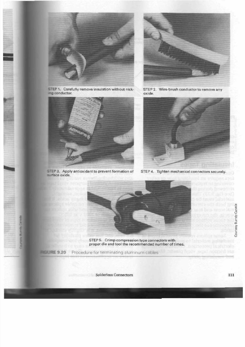
8/19/2019 Applications Electrical
http://slidepdf.com/reader/full/applications-electrical 116/447
1. C ar e fu l ly r em ov e ins u la t ion w i t ho ut n ick - S T E P 2 . Wi r e-br us h c onduc t or t o r em ov e any
•x j
conductor. oxid e.
STEP 3. A pply ant iox idant to prevent form at ion of STEP 4. T ighten mechanical connectors
securely,
surface oxide.
S T E P 5. C r im p c om pr es s ion t y pe c onnec t ors w i t h
proper die and tool the recommended number of t imes.
IE
9.20 P rocedure for termina ting aluminum cables
Solderless Connectors
11
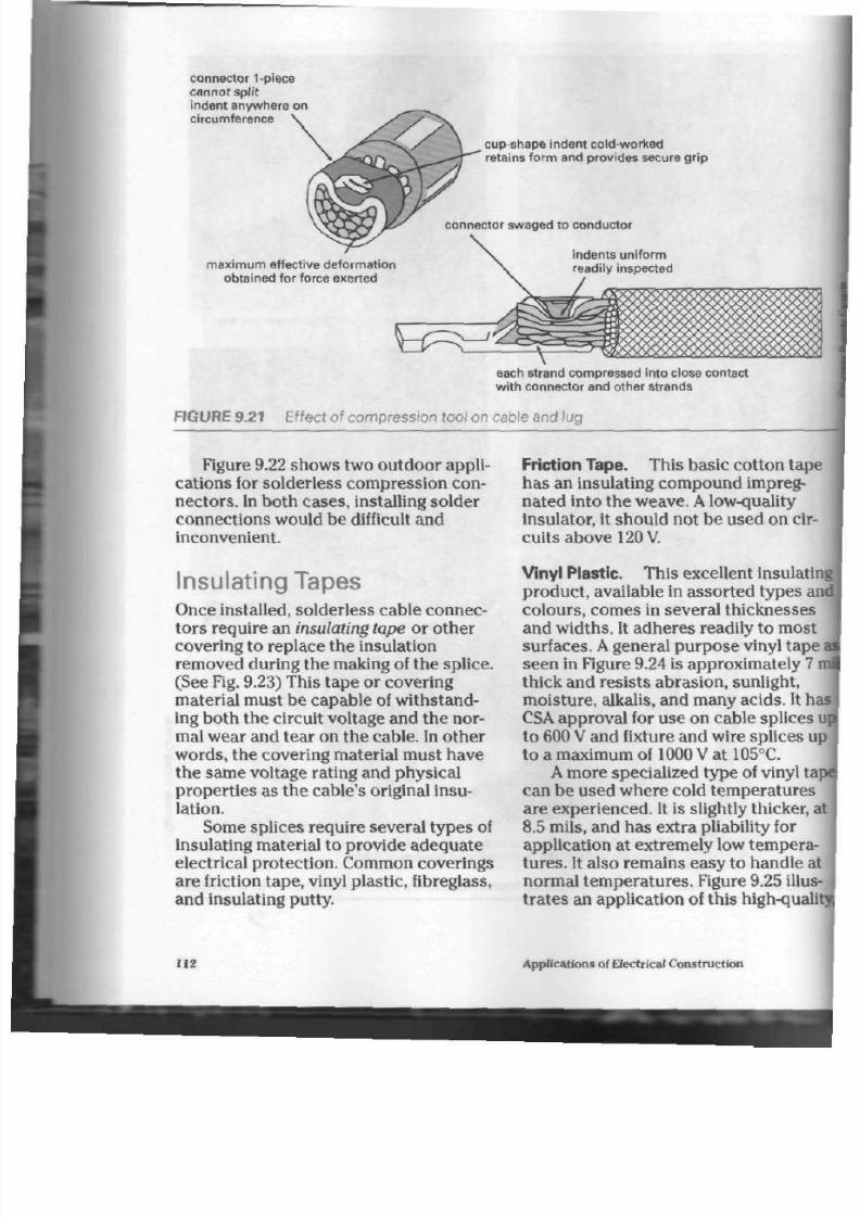
8/19/2019 Applications Electrical
http://slidepdf.com/reader/full/applications-electrical 117/447
connector 1-piece
cannot sp l i t
indent anywhere on
circumference
cup-shape indent co ld-worked
retains form and provides secure gr ip
connector swaged to conductor
maximum effect ive deformation
obta ined for force exer ted
indents un i form
readily inspected
5^EZ
each strand compressed into close contact
wi t h connector and other strands
FIGURE 9.21 E ffect of compression tool on cable and lug
Figure 9.22 sho w s two ou tdo or ap pli
cations for solderless compression con
nectors. In both cases, installing solder
con nectio ns w ould be difficult and
inconvenient.
Insu lating T apes
Once installed, solderless cable connec
tors requ ire an insulating tape or other
covering to replace the insulation
removed during the making of the splice.
(See Fig. 9.23) Th is tap e o r cov ering
material must be capable of w ithstand
ing both the circuit voltage and the nor
mal wear and te ar on the cable. In other
word s, the covering material must hav e
the sam e voltage rating and p hysical
properties as the cable's original insu
lation.
Some splices requ ire severa l type s of
insulating m aterial to provide ade qua te
electrical protection . Common coverings
are friction tape, vinyl plastic, fibreglass,
and insulating putty.
Friction Tape. This basic cotton tape
has an insulating com pound impreg
nated into the weave. A low-quality
insulator, it sho uld not be used on cir
cuits above 120V.
Vinyl Plastic.
Th is excellent insulatin
prod uct, available in assorte d types a
colou rs, com es in several thicknesse s
and w idths. It adh eres readily to m ost
surfaces. A general purpo se vinyl tape
seen in Figure 9.24 is approx imately 7
thick and resists abrasio n, sunlight,
m oisture , alkalis, and many a cids. It h
CSA approval for use on cable splices
to 600 V and fixture and wire splices u
to a m aximum of
1000 V
at 105°C.
A more specialized type of vinyl ta
can be used where cold tem peratures
are e xpe rienc ed. It is slightly thicker, a
8.5 mils, and has extra pliability for
application at extremely low temp era
tures.
It also rem ains eas y to hand le a
normal tem pera ture s. Figure 9.25
illus
trates an application of this high-quali
112
Applications of Electrical Con struction
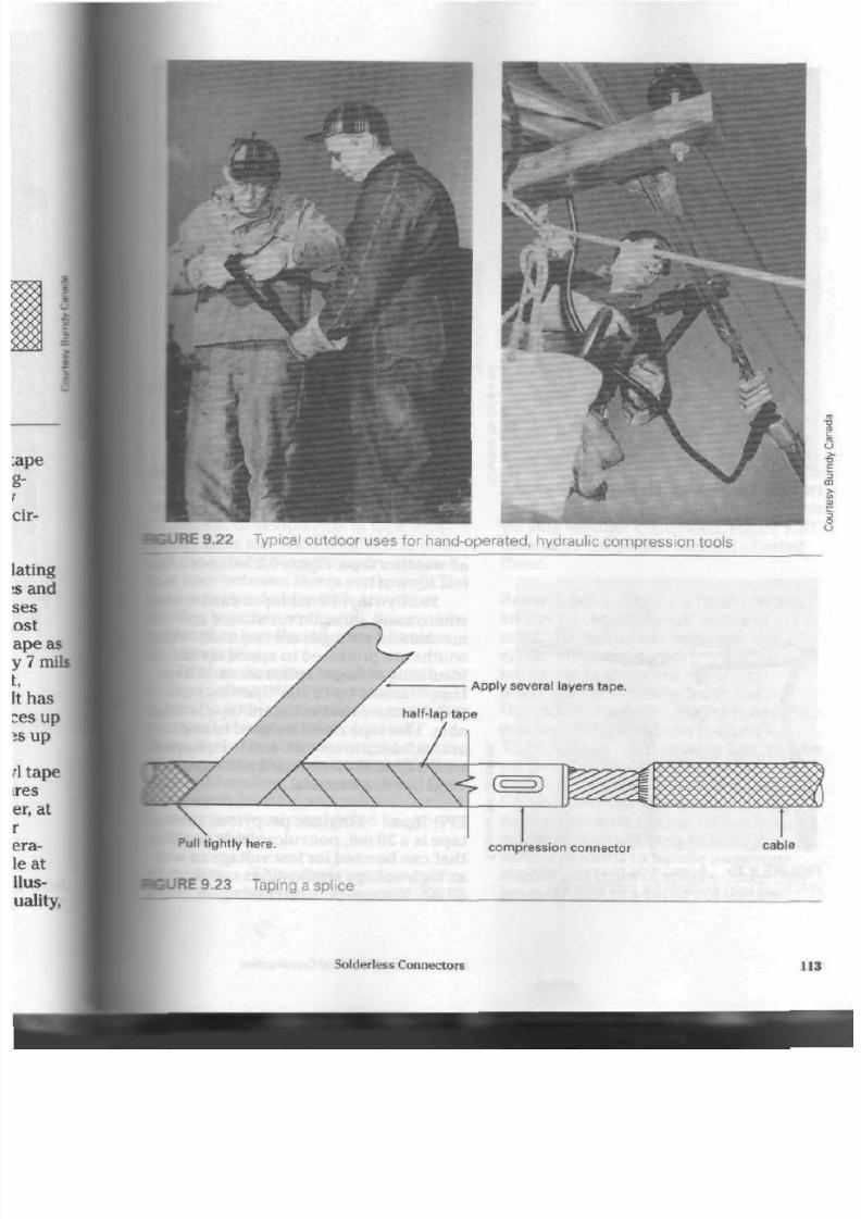
8/19/2019 Applications Electrical
http://slidepdf.com/reader/full/applications-electrical 118/447
JRE 9.22 T ypical outdoor uses for hand-operated, hydraulic com pression tools
Apply several layers tape.
Pull t ightly here.
compression connector
cable
JRE 9.23 Taping a splice
Solderless
Connectors
11

8/19/2019 Applications Electrical
http://slidepdf.com/reader/full/applications-electrical 119/447
FIGURE 9.2 4
electrical tape
General purpose vinyl plastic
FIGURE 9. 26 High-quality, all we ather
i
FIGURE 9 .25
A pplication of vinyl plastic
electrical tape suitable for cold w eather
5
all we ath er tap e. Figure 9.26 show s a
ical form of it.
Sturd y vinyl 10 mil tape s can b e
where more abrasion resistance and
mechanical strength are required. W
widths are produced to speed up th
insulating of larger splice are as. Wh
temp eratures up to
105°C
are en cou
tered, a more heat-resistant tape is a
able. This tape co uld b e used in and
around electric motors and is equip
with a special oil resistant adhesive
vinyl backing m aterial.
EPR
Tape.
Ethylene propylene ru
tape is a 30 mil, nonvulcanizing mate
tha t ca n b e used for low voltage as w
as high voltage applications up to
69 000
V.
It can be stretche d upon
114
Applications of Electrical Construction

8/19/2019 Applications Electrical
http://slidepdf.com/reader/full/applications-electrical 120/447
: 9.27 High and
low
voltage,
EPR,
sss rubber splicing tap e w ith a 130°C
ppfication
to ten t imes its normal
sigth, thu s forming a m oisture-tight
[taper
over the sp lice. (See Fig. 9.27)
Recent developm ents in tape tech-
togy have led to the production of an
• ape that d oes not require a separa-
liner between layers on the roll. The
prevented older-style tape from
ring tog ethe r on the roll. It was often
rard
to
handle
and
messy
to
clean
I after taping .
The new linerless tape has a unique
to dissipate any heat from the
;. Its
stable prop erties improve the
:al,
electrical, and phy sical
icteristics
of the tape up to a maxi-
i operating tem perature of 130°C.
self-bonding,
flame-retardant
tape
tinguishing
and
suitable
for use
previously restricted to spe-
products.
Ir eg la ss . This tape is used on splices
tere the tem per ature may reac h 130°C.
It has a pres sure sensitive, therm o
setting adhesive that m akes it suitable
for use in such high tem peratu re appli
cations as furnace c onnec tions, wa ter
heaters, etc.
Insulating Putty. Large co nn ect ors
requ ire good quality insulation that will
fill voids and pad any irregular shapes
produced by the con necto r. An electrica
grade , rubbe r-ba sed, self-fusing elastic
type putty is available in tape form for
the insulating of large con nec tors. It
should be used on low voltage circuits
(600 V or less) wh ere it will resist aging
and not dry out. Figure 9.28 illu stra tes
the proper m ethod
of
insulating
a
large
connector.
Another form
of
insulating pu tty
is
the vinyl mastic p ad. (See Fig. 9.29 on
page
117.)
These pad s consist of a self-
fusing, rubber-b ased com pound with a
strong adh esive. They mould around dif
ficult shapes and have excellent resist
ance to alkalis, acids, m oisture , and
varying wea ther cond itions. Figure 9.30
illustrates the proper m ethod of using
them.
Resin Splicing K its.
A
resin splicing
kit can be ob tain ed w ith sufficient
materials included to comp lete one
splice. A plastic mould, funnels, insu
lating and sealing com pound , and
pouring resin are included in the kit.
Figure
9.31,
on page 118, illustrates the
pouring of the resin into the m ould.
Th ese u nique "field splicing kits" can be
used for overhead, underground, or
direct burial applications up to 5000 V.
Figure 9.32 illus trate s
a
cutaway
of a
resin splice after the mould has been
removed. Th e kits are available in a
variety of forms to handle numerous
shapes and types of splices. Since the y
are produced in a variety of voltage
Solderless Connectors
U
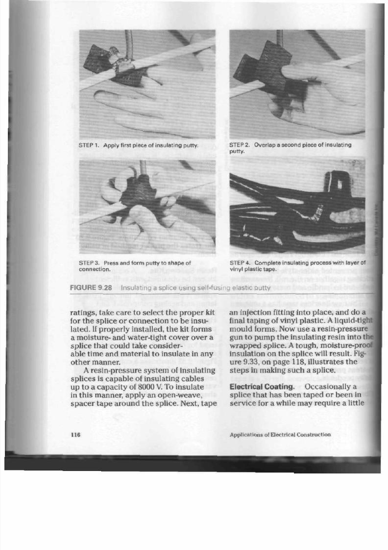
8/19/2019 Applications Electrical
http://slidepdf.com/reader/full/applications-electrical 121/447
S T E P
1.
A pply f i rs t p iece of insulat ing putty.
STEP 2. O ver lap a second piece of insulat ing
putty.
STEP 3. Press and form put ty to shape
of
connect ion.
STEP 4. C omplete insulat ing process with layer of
vinyl plast ic tape.
FIGURE 9.28 Insulating a splice using self-fusing elastic putty
ratings, take c are
to
select the prop er kit
for th e splice
or
connection
to be
insu
lated.
If
prop erly installed, th e kit forms
a mo isture- and w ater-tight cover o ver a
splice tha t could take conside r
able time an d material to insulate in any
other manner.
A resin-pressure system of insulating
splices is cap able of insulating cables
up
to a
capac ity of 8000 V. To insulate
in this m anner, apply an open-weave,
spacer tape around the splice. Next, tape
an injection fitting into plac e, and do
a
final tapin g
of
vinyl plas tic. A liquid-tigh
mould forms. Now use
a
resin-pressure
gun
to
pu m p the insulating resin into
tf
wrapped splice. A tough, moisture-pro
insulation on th e sp lice will resu lt. Fig
ure 9.33,
on
page
118,
illustrates
the
s teps
in
making such
a
splice.
Electrical Coating. Occasionally
a
splice that has been taped
or
been in
service
for a
while may require a little
116
Applications of Electrical Construction

8/19/2019 Applications Electrical
http://slidepdf.com/reader/full/applications-electrical 122/447
C
9.29 Vinyl ma stic insulating ma terial in roll and pad form at
M .
Remove backing.
STEP
2. P osi t ion pad .
? 3 . W r a p a r o u n d .
STEP
4. Insulat ion com pleted.
PRE 9.30 P roper technique for insulating with vinyl mastic pads
Solderless Connectors
11

8/19/2019 Applications Electrical
http://slidepdf.com/reader/full/applications-electrical 123/447
FIGURE 9.31
mould
P ouring resin into a splicing
STEP
1.
Apply an open
weave,
spacer tape to
splice.
FIGURE 9.32 C utaway view of a com pleted
resin insulated splice
extra moisture proofing or insulating. A
liquid, brush-on coating is available
to provide this extra protection when
required. Figure 9.34 shows this productbeing applied to a taped splice.
Coloured Tapes.
Vinyl tape is avail
able in eight, fade-resistant colours:
red, yellow, blue, green, white, orange,
brown, and grey. Tape in these colours
STE P 2. Install injection f it t ing and cover. S plic
area with plastic vinyl tape.
t
STE P 3. Force resin into splice with
resin-press
g u n .
Avoid excessive pressure to prevent bulgi
of tape.
FIGURE 9.33 Insulating a splice using th
resin-pressure system
118
Applications of Electrical Construction
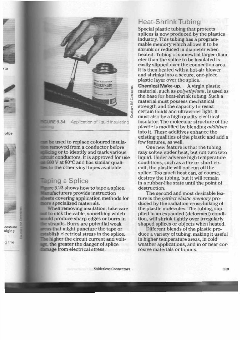
8/19/2019 Applications Electrical
http://slidepdf.com/reader/full/applications-electrical 124/447
•GUftE 9.34 A pplication of liquid insulating
• be used to replace coloured insula-
noved from a conductor before
Scing
or to identify and mark v ariou s
nrit conductors . It is app roved for u se
600 V
at 80°C and ha s similar quali-
i
to the oth er vinyl tape s available.
Jping a S plice
19.23
shows how to tape a splice,
lufacturers provide instruction
ts covering application methods for
: specialized m aterials.
When removing insulation, take care
I to nick the cab le, something which
wild produ ce sha rp edges or burrs in
stran ds. Burrs are potential weak
i
that might puncture the tape or
>lish electrical str es s in th e sp lice.
higher the circuit current and volt-
,
the greater the danger of splice
lage
from electrical stre ss.
Heat-Shrink Tubing
Special plastic tubing that protects
splices is now produ ced by the plastics
industry. This tubing has a program
mable memory which allows it to be
shrunk or reduced in diameter when
heated. Tubing of somewhat larger diam
eter than the splice to be insulated is
easily slipped over the connection area.
It is then heated with a hot-air blower
and sh rinks into a secure, one-piece
plastic layer over the splice.
Chem ical M ake-u p. A virgin plastic
material, such as polyethylene, is used as
the base for heat-shrink
tubing.
Such a
material must possess mechanical
strength and the capacity to resist
certain fluids and ultraviolet light. It
mu st also b e a high-quality electrical
insulator. The molecular structure of the
plastic is modified by blending additives
into it. These additives enh ance the
existing qualities of the p lastic and a dd a
few feature s, a s well.
One new feature is that the tubing
may soften und er heat, but not turn into
liquid. Under adve rse high tem pera ture
con dition s, such a s a fire or short cir
cuit, the plastic will not run off the
splice. Too much heat can, of course,
des troy th e tubing, bu t it will remain
in a rubber-like sta te until th e p oint of
destruction.
The second and mo st desirable fea
ture is the perfect elastic mem ory pro
duced by the radiation cross-linking of
the plastic m olecules. The tubing, sup
plied in an expanded (deformed) condi
tion, will shrink tightly over irregularly
shaped splices or objects when heated.
Different blends of the plastic pro
du ce a varie ty of tubing, making it useful
in higher temp erature areas, in cold
weather applications, and in or near cor
rosive ma terials or liquids.
Solderless
Connectors
119

8/19/2019 Applications Electrical
http://slidepdf.com/reader/full/applications-electrical 125/447
Types of Heat-Shrink
Tubing
Two main types of this tubing are used
extensively in industry.
Polyolefin
tub
ing, a simp le, heat-shrin k tub ing, is one
of the m ost popula r type s for covering
splices or electrical conn ecto rs. (See
Figs.
9.35 and 9.36)
A
second type of tub
ing, known a s
dual-wall
tubing, has a n
outer tube of polyolefin and an inner
tub e of adhesive-type plastic wh ich will
form a perfect seal around the splice or
connection. This seal is capable of keep
ing out all dirt, moisture, va pou rs, etc .
Th e inn er sealing w all is simp ly a differ
en t blend of polyolefin having a dh e
sive/sealing pro pertie s. (See
Figs.
9.37
and 9.38)
t
FIGURE 9.35 P olyolefin, heat-shrink tubing
placed over a crimp-on connector
§
FIGURE 9.36 W hen heated the tubing will
shrink to form an insulating barrier over any
shape of connector or splice.
FIGURE 9.37 Dual-wall polyo lefin, heat-
shrink tubing, placed over a multi-conductor
splice
FIGURE 9.38 Dual-wall
polyolefin
tubing
I
capable of waterproofing splices and conn?
t ions to components.
Heat Source
The approved method of heating the
tubing is with a hot-air conv ection heat
blower as shown in Figure 9.39. Shrink
tem peratu res rang e from 80°C to 150°C
depending on the blend of polyolefin
being used. In the lower hea t rang es,
a standard hair dryer can shrink the
tubing.
When emergency situations arise
and a blower is not av ailable, a flame
from a m atch or oth er low-level flame
120
Applications of Electrical Co nstruction

8/19/2019 Applications Electrical
http://slidepdf.com/reader/full/applications-electrical 126/447
RE 9.39 Hot-air gun in use w ith heat
ing to activate the elastic memory
e can be used. Relying on a flame
uld
not be don e in general prac tice
•• e v er : care must be taken not to
ceed
the plastic's temp eratu re rating.
Fig. 9.40)
JURE 9.40 L ow temp erature flame being
eat-shrink tubing wh ere power is not
Appl icat ions
Due to th e simple application proc ess
and nea tness of the com pleted job,
many u se s have been found for polyole-
fin tubing. There are ten major c olou rs,
as well as clear plastic, available for t he
identification of conductors or connec
t ions. Colours with strip es a re also avail
able to provide an even greater n umb er
of identification com bina tions. This
high-quality insulating product can hold
conductors in groups for the separation
of circuits and easily cover co mp lex con
nectors or terminals. Heat-shrink tubing,
with its versatility, has bee n used exten
sively in mass transit vehicles such as
trains, m ilitary ships , aircraft and land
vehicles. Special vers ions of th e tubin g
are also being produced for use in space
satellites . (See Figs. 9.41,9.42,9.43,9.44,
9.45 and 9.46)
FIGURE 9.41 Flexible, general purpose tub
ing for ide ntification of cables
FIGURE 9.42 A dhesive-lined, sem i-flexible,
thinwall tubing w ith a high shrink ratio and
flame-retardant jacket
Solderless Connectors
12
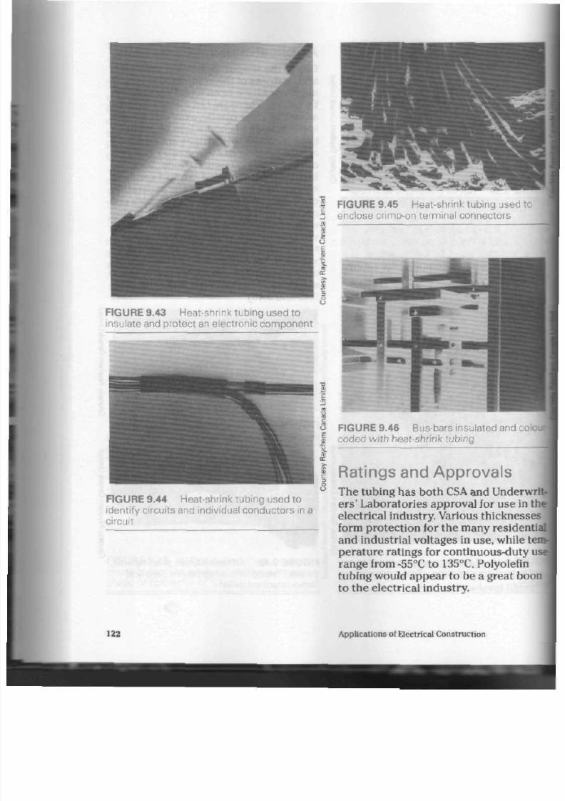
8/19/2019 Applications Electrical
http://slidepdf.com/reader/full/applications-electrical 127/447
FIGURE 9.43 Heat-shrink tubin g used to
insulate and protect an electronic co mp one nt
FIGURE 9. 44 Heat-shrink tubin g used to
identify circuits and individual conductors in a
circuit
FIGURE 9.45 Heat-shrink tubing used to
enclose crimp-on term inal conn ectors
FIGURE 9.46 Bus-bars insulated and colo
coded with heat-shrink tubing
Ratings and Approvals
The tubing has both CSA and Underwr
e r s '
Lab oratories app roval for use in t
electrical industry. Various thicknesse
form protection for the many residentia
and indu strial voltag es in use, while te
pe rature ratings for continuous-duty u
range from -55°C to 135°C. Polyolefin
tubing would a ppe ar to be a great boo
to the electrical industry.
122 Ap plications of Electrical Con struction

8/19/2019 Applications Electrical
http://slidepdf.com/reader/full/applications-electrical 128/447
o r R e v i e w
t two disadvantages of solder
ing and taping wire splices.
>t three ty pes of solderless wire
con necto rs. What is the maximum
circuit voltage for each?
L Why are crimp-on connectors
installed on small stranded con
ductors fastened under terminal
rews?
at arc the disadvantages of
npression connectors?
three reasons why lugs are
ful.
t the ste ps in fastening a co pp er
cab le to a terminal lug.
-t
the ste ps in fastening an alu-
um cable to a terminal lug.
why
should nicks on the stra nds
i cable be avoided when remov-
insulation?
^BThy must a mechanical co nne ctor
be retightened several minutes
after the first tightening?
Describe the methods for crimp
ing copper and aluminum com
pression con nectors t o a cable.
Which two types of protection
must electrical tape provide?
Why is it necessa ry to observ e the
temperature ratings of electrical
tape?
L
List three com mon type s of electri
cal tape.
L Describe how large, irregularly
shaped cable conn ectors are insu
lated.
L What are the advantages of insu
lating putty w hen covering large
or irregularly shap ed splices?
What advantages do resin splicing
kits have over more conventional
methods of insulating a splice?
17. Why must care be taken to select
an insulating product that has the
proper voltage rating?
18.
What are the advantages of using
coloured insulating tapes?
19. Why is it desirable to pull or
stretch the tape s as they are being
applied to the splice area?
20. Under what conditions would a
brush-on, liquid insulating mate
rial be used?
21 . Name the two main ty pes of heat-
shrink tubing in use throughout
the electrical industry.
22.
What advantage has heat-shrink
tubing ove r othe r forms of electri
cal insulation?
23.
List four different applications of
heat-shrink tubing in the care and
protection of electrical wiring cir
cuits.
24. How can heat-shrink tubing be
used in the identification of circuit
terminals and conductors?
25. What methods are used to reduce
the tubing to its final size after
installation on splices or termina
tions?
Solderless Connectors 123
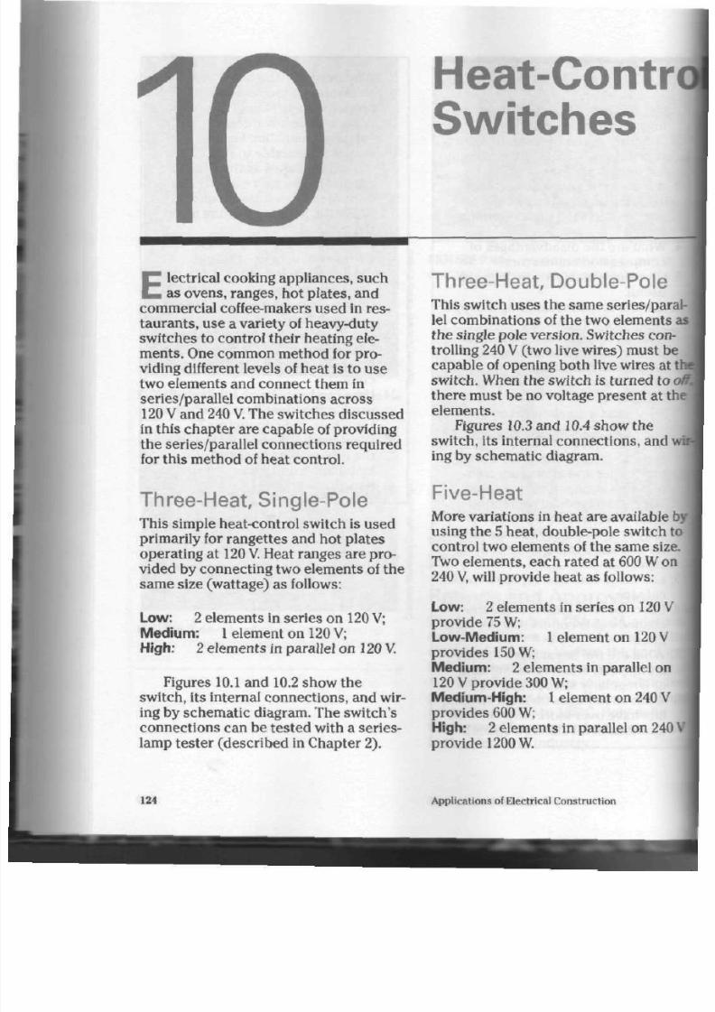
8/19/2019 Applications Electrical
http://slidepdf.com/reader/full/applications-electrical 129/447
Heat-Contr
Switches
E
lectrical cooking appliance s, su ch
as ovens, ranges, hot plates, and
com me rcial coffee-makers u sed in res
tau ran ts, use a variety of heavy-duty
switches to control their he ating ele
me nts. One common method for pro
viding different levels of hea t is to us e
two elements and conn ect them in
series/parallel combinations across
120
V
and 240
V.
The switches discussed
in this chap ter a re capab le of providing
the series/parallel connections required
for this m ethod of he at c ontrol.
Three-Heat, Single-Pole
This simple heat-control switch is used
primarily for rangettes and hot plates
operating at 120 V. Heat rang es are pro
vided by connec ting two eleme nts of the
sam e size (wa ttage) as follows:
Low:
2 elem ents in series on 120 V;
Medium: 1 element on 120 V;
High:
2 eleme nts in parallel on
120 V.
Figures 10.1 and 10.2 show the
switch, its internal con nection s, and wir
ing by schem atic diagram. The switch's
con nec tions can be tested with a series-
lamp teste r (describe d in Chapter 2).
Three-Heat, Double-Pole
This switch uses th e same series/paral
lel com binations of the tw o elements a
th e single pole version. Sw itches con
trolling 240 V (two live wires) mu st b e
cap ab le of open ing bo th live wires at I
switch. When th e switch is turn ed to
i
the re m ust be no voltage present at th
elements.
Figures 10.3 an d 10.4 show th e
switch, its internal conne ctions, and w
ing by schem atic diagram.
Five-Heat
More variations in heat are available b
using the 5 heat, dou ble-pole switch to
control two elements of the same size.
Two elemen ts, each rate d at 600 W on
240
V,
will provide heat as follows:
Low: 2 elem ents in series on 120 V
provide
75
W;
Low-Medium:
1 element on 120 V
provides 150
W;
Medium:
2 elem ents in parallel on
120 V provide 300 W;
Medium-High: 1 element on 240 V
prov ides 600 W;
High:
2 elem ents in parallel on
240
provide 1200
W.
124 App lications of Electrical Con struction
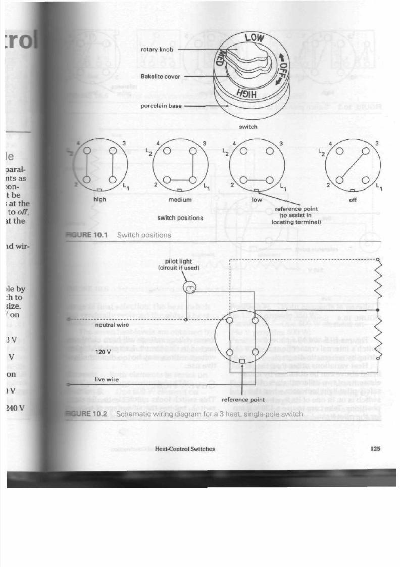
8/19/2019 Applications Electrical
http://slidepdf.com/reader/full/applications-electrical 130/447
z
6
rotary knob
Bakelite cover
porcelain base
switch
h igh
m e d i u m
switch posi t ions
JRE 10.1 S witch positions
reference point
(to assist in
locat ing terminal)
off
pilot l ight
(circuit if used)
neutral wire
1 2 0 V
l ive wire
reference point
JRE 10.2 S chematic wirin g diagram for a 3 heat, single-pole switc h
Heat-Control Switches
125

8/19/2019 Applications Electrical
http://slidepdf.com/reader/full/applications-electrical 131/447
^
L
1
3 N
^ J ^
L
t
h i g h m e d i u m
FIGURE 10.3 S witch positions for a 3 heat, double-pole switc h
reference
point
live
reference point
240 V
live
elen
FIGURE 10.4 S chematic wiring diagram for a 3 heat, double-pole switch
Figures 10.5 and 10.6 show the
switch's internal connections and its
wiring by schem atic d iagram.
Heat variations other than those
listed above can be obtained by using
elem ents of two different sizes. Also, a
safety pilot light indicates when the
switch is on in one of its five h eatin g
position s. Take care to use a 120 V lamp
for the pilot light. Lamps with
lower voltage ratings will burn out if cc
nec ted to this circuit. Lamps with
high
voltage ratings may b e too dim for
effe
tive use.
Seven-Heat
This switch looks m uch like th e 5 heat
switch, but has th e adv antage of two
extra heat-levels. Because of this great
126
Applications of Electrical Construction

8/19/2019 Applications Electrical
http://slidepdf.com/reader/full/applications-electrical 132/447
^ t b - Q - O .
low
low-m edium m edium m edium -h igh h igh
JURE 10.5 Internal sw itch conne ctions (rear view) for a 5 heat sw itch
E 10.6 S chematic wiring diagram for a 5 heat sw itch
•ge of heat selection, the heat switch
B gradually replaced the o lder 5 heat
•itch design.
The seven heat-levels are obtained by
•eg
two different elements, each rated
1240 V. A
600
W
and an 800
W
element
combination provide heat as follows:
i- mer:
Both elem ents in series on
0
V
provide approx imately 87 W.
»rtion 6: One 600 W element on
» V provides 150 W;
ssrtion 5: One 800 W element o n
»V provides 200 W;
Position 4: Both elem ents in parallel
on 120 V provide 350 W;
Position 3: One 600 W elemen t on
240 V prov ides 600 W;
Position 2: One 800
W
elemen t on
240
V
prov ides 800 W;
High: Both elem en ts in parallel on
240 V provide 1400
W.
Figures 10.7 and 10.8 show th e sw itch's
internal conn ection s and its wiring by
schematic diagram.
Most mo dern ra nge s have a pilot
light terminal at the rear of the switch to
Heat-Control
Switches
127

8/19/2019 Applications Electrical
http://slidepdf.com/reader/full/applications-electrical 133/447
simmer
position 6 position 5 position 4
Q
positio
position 2 high
FIGURE 10.7 Internal switch connections (rear view) for a 7 heat switch
120
V/240
V
o--
live
neutral
live
O N
h o -
O
L
2
1 2 3 4
0 0 0 0
element
,_yw\A
element
^ *
AAA/VH,
FIGURE 10.8 Schematic wiring diagram for a 7 heat switch
show whether the element is on.
An
ele
ment that has been left on may not glow
red but still be hot enough to burn a per
son touching it.
Infinite-Heat
Improvements in the design of electric
ranges created a need for a greater vari
ety in heat levels. The infinite-heat
switch, as the name implies, offers an
unlimited variation in heat level.
Although this switch is often
more ex
sive than other heat control switches
a single element requiring less wiring
offsets this initial cost.
Figure 10.9 shows by schematic
ing diagram the internal workings of
typical infinite-heat switch.
128
Applications of Electrical Construction

8/19/2019 Applications Electrical
http://slidepdf.com/reader/full/applications-electrical 134/447
pi lot l ight terminal
l ine terminal
main contacts
bimetal s t r ip
heater coil
of switch
pilot l ight contact
l ine contacts
element terminal
N O T E :
S wi t c h
in off posit ion
RE 10.9 Schematic wiring diagram showing infinite-heat switch parts and circuit
Operation of Infinite-Heat Sw itch .
{cam
is fastened to the knob of the
tch. One of the
main
con tacts is on a
wnetal strip fitted in to a tension arm.
a the knob is turned slightly, th e cam
Ktuates the tension arm . The arm
Btates
on the pivot and closes the main
aontacts, thu s heating th e elem ent.
A h eater coil
is wound around the
aetal strip and conn ected in parallel
the element. The heat from the
eater coil warms the bimetal strip and
causes the strip to bend outwards. This
j>ens the circuit, and the hea ter cools.
:
strip contracts and closes the con-
ts .
This activates the element and
heater again.
The more the knob is turned , th e
•o r e it cau ses the tension arm to ex ert
pre ssu re on the con tact s. Therefore, it
takes longer for the heater to b ecom e
hot enough to actua te the bimetal strip
and open the contacts.
The single eleme nt o pe rate s at full
power each time the contacts are
closed, and the heat level is regulated by
the speed at which the main co ntacts
open and close. The num ber of opera
ting cycles in a given period of time a nd
the length of time the elem ent is on in
each cycle is controlled by the amount
the knob on the switch is rotated.
A pilot light terminal simplifies the
conn ection of a light to in dicate th e on
position. Figure 10.10 illustrates the
internal layout of a typical infinite-heat
switch.
Heat-Control Switches
129
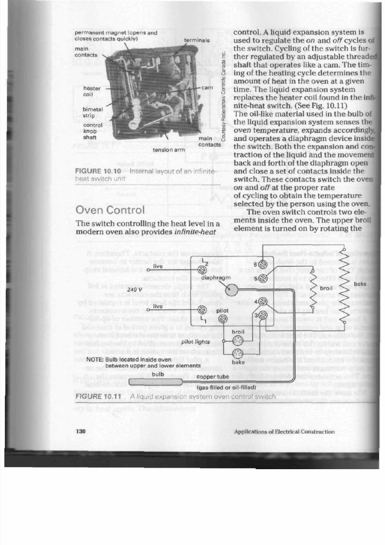
8/19/2019 Applications Electrical
http://slidepdf.com/reader/full/applications-electrical 135/447
permanent magnet (opens and
closes contacts quickly)
terminals
bimetal
str ip
control
k nob
shaft
tension
arm
FIGURE
10.10 Internal
layout of an infinite-
heat switch unit
Oven Control
The switch controlling th e he at level in a
modern oven also provides infinite-heat
:
control.
A
liquid expa nsion s ystem is
used to regulate th e on and off cycles
th e sw itch. Cycling of the switch is fu
ther regulated by
an
adjustable threa
shaft that operates like a cam. The tim
ing of the heating cycle determine s th
amount of hea t in the oven at a given
time. The liquid expansion system
replaces the heater coil found in th e
nite-heat sw itch. (See Fig. 10.11)
The oil-like material used in the bulb
the liquid expansion system sens es
th
oven tem perature, expands
according
and operates a diaph ragm device ins
the switch. Both the expansion and c
traction
of
th e liquid and th e movem
back and forth of the d iaphragm open
and close a se t of contac ts inside the
switch. These co ntac ts switch the ov
on and off at the proper rate
of cyc ling to obtain the temperature
selected by the p erson using the oven
The oven sw itch con trols two ele
ments inside the oven. The upper bro
element is turned on by rotating the
live
240 V
live
.2 6(g
diaphr agm 5(§?
> >
f
pilot
pi lot l ights
4
< 1
NOTE: Bulb located ins ide oven
between upper and lower elements
bu lb
broi l
}-©—'
-©
bake
broil
bake
r
copper tube
(gas-f i l led
or
oil-f i l led)
FIGURE 10.11 A liquid expansion system oven control switch
130 Applications
of
Electrical Construction

8/19/2019 Applications Electrical
http://slidepdf.com/reader/full/applications-electrical 136/447
d the switch to the broil
position,
•anufacturers design the oven
o
that
it
will rem ain in
a
slightly
losition
for this operation. They
• l e n d
that broiling be done with
• e n door partly open to ensure
•en temp erature does not get hot
to cycle the c onta cts. The broil
twill
then remain
on,
necessitat-
1
food watching
if
burning is
to
ided. It is also com mon to have an
•ith an automatic preheat process.
i the oven is being pre heated , the
Element will com e on with th e bake
•L
The broil element will
be auto-
iy
turned off when oven
tempera-
s approx imately 40°C below th e
setting of the sw itch.
Men
tem pera ture will then
be
Bfat to its selected heat level by the
element and kept there as
the
h
cycles on and off during the
tag
proc ess. Having both eleme nts
gether provides a lot of heat and
he oven up to temp erature rather
ly.
The purpose
of
th e broil
ele-
then is
to
preheat the oven an d/or
food qu ickly. The lower bake ele
ment is used for normal heating of the
oven and is und er the con trol of the liq
uid expansion system
at
all tim es.
Pilot lamps are norm ally included
in
the oven circuit
to
indicate when the ele
ments are on and producing heat in th e
ove n. Figure 10.12 illustra tes th e internal
layout
of a
typical oven con trol sw itch.
Self-Cleaning Ovens
Ovens with a self-cleaning feature do
not req uire spilt or burnt food to be
remov ed from t he w alls and floor of the
oven through the use
of
stron g cleaning
materials. They thereby eliminate
a
tedi
ous and often messy process.
Continuous Cleaning Type.
This oven
uses its normal cooking temperature
to gradually reduce the b urned food
particles
on
its inner surfac es. An oven
cleaned this way doe s not appe ar to be
as clean as on e of the sec ond ty pe and
the proc ess takes m uch longer.
Pyrolytic Self-Cleaning Type.
This
oven, with its more efficient cleaning
bake terminal
-copper tube
line terminal
d ia p h ra g m me ch a n ism
10.12 Internal layout of an oven control switch
Heat-Control Switches
131

8/19/2019 Applications Electrical
http://slidepdf.com/reader/full/applications-electrical 137/447
system, uses a high oven te m pera ture
over a sh ort er period of time to re du ce
food particles to an easily removable ash.
A pyrolytic oven relies on a co ntrol
switch-and-circuit that o pe rate s in much
the same manner as the temperature-
sensitive expansion system used in regu
lar oven switches. However, the control
switch-and-circuit has more functions to
perform than the expansion system.
The oven temp erature reaches approxi
mately 480°C during its cleaning cycle,
and as mentioned abo ve, reduces food
spill-overs to a small am oun t of ash
(muc h like a ciga rette ash ) in an ho ur
or two. This ash can then be easily
removed, leaving the oven clean and
read y for future us e.
Due to the much higher tempe ra
tures in this type of oven, the oil-like
material in the expansion s ystem is
replaced w ith helium ga s.
A
larger bu lb
accommodates the amount of helium
required to ope rate the diaphragm in the
switch.
This type of control switch may have
up to four different sets of contacts, all
of which are set to operate at different
temperatures and open and close the
various circuits as the gas-filled expan
sion system d ictates. One set of con tacts
would be for baking and broiling, while a
second set would be calibrated at the
factory to op erate th e oven at high tem
pera ture during the cleaning cycle.
Although oven temperatures are
high d uring t he cleaning cycle, only a lit
tle electricity is used. That is because
the elemen ts are conn ected in such a
manner that they operate at 120 V, pro
ducing less tha n the ir full wa ttage, b ut
staying on throu gho ut th e cycle. The ele
ments are not cycled on and off as fre
quently as they are during the cooking
operation, bu t are allowed to pro duc e
heat for a longer period of time. Extra
insulation is usually put into a self-clea
ing oven to a ssist th e elemen ts in
obtai
ing the proper temperature and preven
excessive heat from passing through to
the ou ter surfaces of the stove
itself.
A third set of contacts can be used
engage a latching mechanism in the
oven door. This prevents the door from
being open ed during the high tempera
tu re cleaning cycle. Th e oven do or latc
ing mechanism is set to keep the do or
closed whenever oven tem perature
ex cee ds 320°C for two safety rea son s.
First, burns to hands or face can be
severe when oven surface and air tern-
peratures reach this level. Second, a su
den inflow of oxygen from the air as the
oven doo r is open ed can cause food pa
tides
in the oven to burst into flames
when th e temp eratu re is in the high
range used for cleaning.
A
fourth set of co nta cts on th e
switch can be used to hold the food at
warm temperature, after the baking pro
cess,
until you are ready to eat the foo
This temp eratu re is approximately
80°C
Most modern ovens have useful
timer circu its built into their control
panels. Ovens can be set to come on at
predetermined hour of day or night, to
cook for a preset length of time, and to
sh ut off or keep food w arm un til need*
Elements, receptacles, and m inute mil
ers can all be timed and/or controlled.
Figure 10.13 illus trate s a circuit
dia
gram for a self-cleaning oven. All
switches co ntained within the do tted
lines are controlled by the gas-filled
expansion system . The door-lock switd
ope rates the door-lock solenoid, or
electrically powered, magnetic latch
assembly, once th e clean cycle has be
selected and preve nts the door from
being opened during the cleaning open
tion. The door's electrical interlock (5i
6) prevents the solenoid from releasin
132
Applications
ol
Electrical Construction

8/19/2019 Applications Electrical
http://slidepdf.com/reader/full/applications-electrical 138/447
L
2
Q
240 V pow er s upply
Al l switches within dot ted
l ine are control led by
thermostat ,
(gas-f i l led bulb)
O L ,
-a-"
o-
door lock
switch
* "
O-
manual
door
interlock
^ C
5 6
door lock switch
electr ical interlock
keep warm switch
- /
8
main
cycl ing
contacts
3 4
hi temp,
clean -
switch
door lock
jy /solenoid
gr ound
broi l e lement
t her m al
relays
function selector
switch on control
panel
URE 10.13 A self-cleaning oven circuit
bake element
\door once the oven temperatu re
che s cleaning level.
The manual door interlock switch
asses
the norm al cycling con tacts,
i removing the expansion sy stem
xn the circuit for the cleaning o per-
kxi and allowing the oven to reach
D°C. A hi-temp clean switch preve nts
le oven from rising abo ve the desired
leaning tempe rature.
The function switch located on
Heat-Control Switches
the control panel of the stove/oven is
used by the owner to select bake, broil,
preh eat, etc ., functions for the oven .
Both bake and broil elements are further
controlled b y a therm al relay (part of th e
gas expansion system) which controls
their cycling to obtain p rope r oven tem
pera ture as selected by the o perator.
Figure 10.14 illustrates the internal lay
out of a self-cleaning oven switch, pyro-
lytic
type.
133

8/19/2019 Applications Electrical
http://slidepdf.com/reader/full/applications-electrical 139/447
E xternal View
control knob shaft
insulat ing sleeve
Bourdon tube replaces diaphragm
(expanding spiral act ion)
Internal View
gas (heliurn)-f i l led bulb
FIGURE 10.14 A self-cleaning, pyrolytic oven control switch
Recent developm ents in suc h
switches ha ve brought ab out th e use of
a sodium/potassium-filled tube and bulb
expansion system . The sod ium/potas
sium m ixture turn s into a liquid
at
oven
operat ing tempe ratures, expanding to
operate
a
bellows dev ice in the switch.
A
higher degree
of
sensitivity is obtained
with the new expansion system, bu t th e
electr ical conta cts opera te in much the
same m anner as previous switch m echa
nisms.
Rotisserie.
Many mod ern ovens
are
equippe d with a motor driven u nit to
rotate foods w ithin the o ven while
cooking. Juices from th e food being
cooked fall from the rotating unit and
can often land on the lower bake
eleme nt. To preven t smoking of these
grease s, the broil element is used
by
many m anufacturers for the rotisseri
cooking cy cle. Its location in th e upp
par t of the oven p reven ts dripping pz
cles from landing on it, thu s red uc
ing the smo ke p roblem .
When selecting the cooking temp
ture for rotisserie cooking, the switch
kn ob is rotated clockw ise to th e broi
position, and then backed off to the
desired cooking tem peratu re. This
engages the broil element only, throu
a mechanical selection system built
i
th e front of th e switch, an d allows the
broil element to heat th e oven while
being controlled by the gas exp ansio
system.
134
Applications
oi
Electrical Construction

8/19/2019 Applications Electrical
http://slidepdf.com/reader/full/applications-electrical 140/447
o r R e v i e w
List four appliances that use heat-
rol switches.
ain how three levels of heat
\»re obtained with the 3 heat
switch.
Of what use is the reference point
n the ba se of a 3 heat switch?
must
heat-control switches
opera ting on 240 V be c apa ble of
ipening
both live wires?
W hy has the 7 heat switch gradu-
replaced
the older 5 heat
i tch?
iy
is a pilot light an im por tan t
ure on heat-control switches?
two advantages the infinite-
at switch has over other heat-
ltrol switches,
lain in your own wo rds the
ration of the infinite-heat
tch.
ere is the oil bulb for an oven-
rol
switch located?
What precaution must be taken
when using the broil element?
itate
two advantages of the
self-
cleaning oven.
Which type of self-cleaning oven
cleans th e best? Explain why.
is the high tem peratu re
obtained for the cleaning cycle of
a self-cleaning oven?
Explain why extra insulation is
required around a self-cleaning
oven.
What are the advantages of an
electrically timed oven circuit?
Heat-Control Sw itches 135

8/19/2019 Applications Electrical
http://slidepdf.com/reader/full/applications-electrical 141/447
A
rmoured cable (A/C) can be used
for both open and concealed wiring
sy ste m s. Unlike NMSC, it may be ru n on
the surface of walls and ceilings in build
ings of mason ry con struction .
Armoured cable is widely used as a
quick metho d for distributing power
throughout new industrial plants, adding
to existing plants, and relocating
machinery. It can also be used in public
and commercial buildings where the
possibility of physical damage to the
cable makes NMSC unsu itable .
Armoured cable is more flexible than
rigid conduit systems. It can be installed
in long continuou s run s without need for
joints and splices. Conduit system s,
however, require a box or fitting after
each 30 m of conduit and/or after an
accumulation of 360° of bend to ease the
pulling in of the con du ctor s.
Electrical Ratings
Unlike NMSC, A/C has a continuous
protective m etal covering, and so is
approv ed for use on circuits up to
600 V
maximum. It is available in 1,2,3, and 4
conductor combinations, ranging in size
from No. 14 t o No. 4/0. Larger co ndu c
tors may be made to order.
Individual cond ucto rs in the cable
used to be covered w ith a cotton-braid-
Armoured
Cable
over-rubber insulation which was
for use at a maximum temperature
60°C.
Chang es in th e C anadian
Ele
Code have resulted in improvem en
in the insulation on these conduc
Modern A/C cond uc tors are insula
with a durable material called
Cr
(X-Link). X-Link has a maximum
te
ature rating of 90°C.
Trade Names
Armoured cable was originally kn
armoured bushed cable (ABC),
bec
small, anti-short bushing w as inse
in to the end of each cable
termina
How ever, ins talle rs often refer to A
simply as
BX
or BXL.
BXL
refers t o
type that has an intern al lead shea
over the conductors.
Cable Construction
Figure
11.1
show s the materials us
the c onstru ction of the older style
A/C. Figure 11.2 shows modern ca
construction.
One type of armou red cable ha
lead she ath placed be tween th e co
ductors and the armour. This shea
prevents m oisture or chemicals fr
entering the conduc tor portion of
cable. Th e she ath makes the cable
136
Applications of Electrical Construction

8/19/2019 Applications Electrical
http://slidepdf.com/reader/full/applications-electrical 142/447
able for outdoo r use or direct burial
ie ea rth . (See Fig. 11.3) The
utnum
arm our on m ost A/C, how-
t corrodes severely when placed
ler ground. Therefore, steel is used as
placement on the cable for outd oo r
(•nderground use (ACL).
Ie
T ermination
first step in fastening A/C to a box or
is to remove the armour with a
copper
black
cot ton braid
a lum inum s t r ip gr ound
Doe' insulat ion
paper
a l u m i n u m a r m o u r <S
11.1 O lder style 3 conductor
oured cable
RW-90
(X-link)
insulat ion
whi t e
.copper
g r ound w i r e
S
<
black paper
a lum inum ar m our
E
11.2
Mod ern flexible armo ured
RW-90 (X-link) insulat ion
fcned
copper
red
whi t e \
black
V
lead
/
\V^\
paper
\
kjlation
galvanized steel
ar m our
H E 11.3 A C L flexible armoured cable
c
3
33333)
S T E P
1.
Cut t h r ough
2 wrap s of armo ur
at appr ox im at e ly
45°
833333333*
paper wr app ing
mssssQ
S T E P 2. Rotate armour
and remove f rom cable.
Remove paper wrapping.
anti-short
bushing
STEP 3. Insert bu shing
between armour
and conductors.
grounding st r ip
T ighten locknut .
ant i -short bushing
(can be seen here)
Secure grounding st r ip
under connector c lamp.
STEP 4. T ighten conn ector on cable.
Install connector in box.
FIGURE 11.4 P rocedure for terminating
armoured cable in box
Armoured Cable
137

8/19/2019 Applications Electrical
http://slidepdf.com/reader/full/applications-electrical 143/447
>•
outlet
box
ground screws
cable clamp
15
cm free conductor
7 X
X X X
XT -
anti-short bushing
swi tch mount ing
lug
ground str ip
armoured cable
cable strap within
30 cm of box
FIGURE
11.5
Old-style armoured cable secured to box by built-in clamp
hacksaw. (See Fig. 11.4) Take c are to
remove the correct amou nt of armour
the first time. It is often difficult to hold a
small length of cable for a second cut.
Take care, too,
to
protect the insulation
on the con duc tors from being damaged
by the saw du ring th e cutting. Trim the
paper wrapping around the conductors
as close to the arm our as p ossible.
After removing the armour and trim
ming the p ap er w rapping, fold b ack th e
aluminum grounding strip so that it is
out of the way beside th e cable. Insert a
fibre or plastic anti-short bushing
between the armour and the conduc
tors. This anti-short bushing prevents
the jagged edg es of th e arm our from cut
t ing into th e insulat ion aroun d th e con
duc tors. Once the anti-short bushing is
in place, insert the cable in to an
approved box connector. The box con-
138
nec tor h olds the anti-short bushing
place, secu res the cable to the box o
ting, and c lamp s on to the grounding
strip. Use of it ensures that the g ro u
circu it is co m ple te. (See Figs.
11.5
an
116)
Cables now being produced have
grounding conductor
instead
of an al
num grounding
str ip.
This feature e
inates the need for folding ba ck and
clamping a grounding strip.
Cable Supports
As does NMSC, arm oured cable mus
be suppo rted by an approve d strap
stap le within 30 cm
of
every box. A
maximum of 1.4 m be twee n th e
supp
on the cable run is allowed. If th e ca
is run through wood en joists , it mus
be kept back at least 3 cm from th e f
Applications
of
Electrical C onstruction
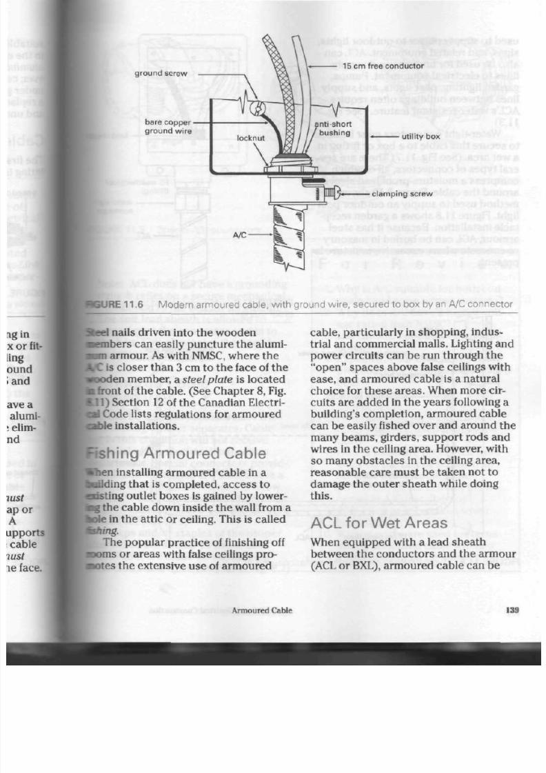
8/19/2019 Applications Electrical
http://slidepdf.com/reader/full/applications-electrical 144/447

8/19/2019 Applications Electrical
http://slidepdf.com/reader/full/applications-electrical 145/447
used
to
supply p ower to outd oor lights,
signs, and
related equipment. ACL can
also
be
used
for
underground supply
lines
to
electrical equipm ent. P um ps,
garden lighting, post lights, and supply
lines between buildings often require
ACL's water-resistant feature. (See Fig.
11.3)
Water-tight connectors must b e used
to sec ure this cable to a box or fitting in
a wet area. (See Fig. 11.7) There are sev
eral typ es
of
conn ecto rs, all of w hich
compress
a
moisture-proof lead sleev e
around the cable. Figure 8.10 shows this
method used
to
supply an outdoor post
light. Figure
11.8
shows
a
garden recep
tacle installation. Becau se it has steel
armour,
ACL
can be buried in masonry
or concrete where excessive moisture
is
present.
lea
FS weatherpr
(f it t ing)
wat
conp
FIGURE 11.7 ACL connected to mois
proof fitting
NMSC
w e a th e rp ro o f box and cover
octagon
box
water-t ight connector
w e a th e rp ro o f box
and receptacle cover
I
support
grade level
bolt and nut
house wal
protective board
preservative-treated)
1 m be low grade
L
7—i—in -i -ii i i i i i i r—i r r r r
r'-r
r-7—r
15 cmsand layer ACL
\
suppor
-steel po
FIGURE
11.8
Typical garden receptacle installation using ACL
140
Applications of Electrical Construction

8/19/2019 Applications Electrical
http://slidepdf.com/reader/full/applications-electrical 146/447

8/19/2019 Applications Electrical
http://slidepdf.com/reader/full/applications-electrical 147/447
A l u m i n u m
Sheathed
Cable
A
n aluminum-sheathed cable, which
is a
factory-assembled
wiring sys
tem, is a seam less m etal or welded
wrap
aroun d shea th enclosing a single or mul
tiple conductor assembly. The aluminum
sheath is both vapour- and liquid-tight,
and the condu ctors enclosed in the
sheath can be either copper or alumi
num. Co nduc tors w ere at one time insu
lated by rubber, but are now insulated
by
Cross-Link polyethlene,
rated at a max
imum tem pe ratu re of 90°C.
Smooth-Sheathed Cable
Aluminum -sheathed cable was basically
a
cable-in-a<onduit,
assembled and
tes ted at the factory. Using it
simplif
installation and saved considerable
and labour. While much smooth-shea
cable is still in u se (se e Fig. 12.1),
but man ufacturers are now producir
corrugated cable in all sizes, instead
Corrugated Cable
The conductors of this cable are
enclosed in an oversize aluminum
tu
The tube is then passed throug h a
revolving die
that compresses
two-t
of the tube on to the insulated condu
to rs . (See Fig. 12.2) Th e soft, m etal
arches
allow the cable to b e bent ea
while the w ork-hardened
flat spiral
FIGURE 12.1 O ld-style smooth-sheathed aluminum cable
FIGURE 12.2 C orrugated aluminum sheathed cable w ith a type " W " moisture-proof
connector
142
Applications of Electrical C onstruction

8/19/2019 Applications Electrical
http://slidepdf.com/reader/full/applications-electrical 148/447
)port the co ndu ctors . Large cables
i
thus be bent without the us e of
spe-
I
tools such as tho se requ ired for a
Juit system.
leath Covering
vvinyl chloride (PVC)
jacket is
jded over the aluminum sheath. The
;t enables th e cable to resist corro-
i
chemicals and to b e used under-
ld.
Jackets are made in various
rs to aid identification of circuits
I
voltages.
itrical Ratings
inum-sheathed
cab le is made for
on any voltage require d. Most of th e
ion sizes of condu ctor units are
ily
available with a 600
V
rating. Part
[the
Canadian Electrical Co de lists
current-carrying capacity of the
in its ampacity tables,
rh e conductors of aluminum-
led cable car ry a maximum
tem-
lre
ratin g of
90°C.
igle
Versus
Iti-Conductor Cables
;onductor cables have a much
•current rating
than multi-conduc-
cables with th e sam e gauge of wire.
;fore, it is more econ om ical to us e
single-conductor cables, rather
one large multi-conductor cable, for
truction of heavy-current circuits.
leath Currents
lduc tor carrying electrical current
luces a ma gnetic field aro und
itself.
i
the cur ren t is alternating (AC), th e
gnetic field rises and falls in strength
th e current pulses through
the co nductor. This results in a moving
magnetic
field.
Any metal substa nce w ithin th e
range of this moving magnetic field will
have a curre nt induced into it by the
field. When both ends of the cable are
groun ded on a single-conductor unit, a
circuit is formed and th e shea th curr ents
circulate. The she ath c urre nts of cables
runn ing side by sid e will circulate
between them, if the cables are con
nected t o a comm on m etal box at each
end.
As the shea th curren ts increase in
volume, heat is generated in the she ath.
This heat can be severe enough to dam
age the insulation around the condu c
tor s within the cab le.
Single-conductor cables carrying
higher amounts of current, for example,
425 A and up, must receive special care
when run side by side. Copper cables of
250 MCM and a luminum cable s of 350 MC
and larger must hav e their shea ths insu
lated from one another at one end of the
cable run and be grounded at the oppo
site end. The se measures prevent she ath
currents from circulating within the
cab le sy stem . (See Figs. 12.3 and 12.4)
Note: Do not use m agnetic materials,
such as steel, for suppo rting
single-
condu ctor cables. These suppo rts can
become magnetized and have currents
circulating within them . The se ed dy
curr ents , as they are called, heat th e
supp ort and cause damage to the
cable insulation.
Con nectors used t o termina te single-
condu ctor cables mu st also be mad e
of
nonmagnetic
material. In a three co ndu c
tor system (3 ph ase system ), all three
cables mu st enter th e box or cab inet
through one, nonmagnetic plate. When
this plate is fastened to the bo x or cabi-
Aluminum-Sheathed Cable
143

8/19/2019 Applications Electrical
http://slidepdf.com/reader/full/applications-electrical 149/447
nonmagnet ic box or p late
dry-type or
wet- type connector
a lum inum s heat hs
(smooth A/S or cor f lex)
insulat ing mater ia l
steel box
N O T E :
Gro undin g conductor is required with
insulat ing plate.
FIGURE 12.3 T ypical cable installation (no shea th currents)
^^ground ing
bushing
dry-type or
wet- type connector
supply
alternative method
(if cable no t grounded
on metal box or plate)
a lum inum s heat hs
(smooth A/S or cor f lex)
NO TE: Dry-type connectors prevent edges of
aluminum sheaths from damaging insulated conductors.
NOT E:
Grounding conductor may be required.
FIGURE 12.4 A lternative me thods for grounding cables at boxes (Sheath currents
prese
net where the cables terminate and
currents are in excess of 200 A, serious
eddy c urren ts will not occur at the box.
Multi<onductor cables are more
expensive than the single conductor
units required to replace them , but th ey
tend to eliminate the problem of sheath
curre nts. When two or more conduc
are enclosed by th e same sheath, th
magnetic fields around each condu
cancel one another. Multi-conducto
cables may be encircled or supporte
mag netic m aterials w ithout risk of e
current damage.
144
Applications of Electrical Construction

8/19/2019 Applications Electrical
http://slidepdf.com/reader/full/applications-electrical 150/447
C able T erm ination
1
he old-style
smoo th-sheathed
c ables in
e smaller sizes made use of a connec-
r that was similar to an armoured
M e connector. Both dry-type and
aisture-proof
connectors were used.
P e e Figs.
12.5
and 12.6)
Modern
corrugated
cable requires
•sectors
of a design different from
kat used with smooth-sheathed cable.
loth dry-type and moisture-proof con-
Bctors are available. (See Figs. 12.7 and
US)
Corrugated
cable with a
PVC acket
be term inate d w ith a different typ e
trade size
threaded entrance
of co nn ec tor. (See Fig. 12.9 on page 147.)
P reparation of C able for
Termination
Removing the aluminum shea th from the
cable is easy to d o. Calculate how much
free conductor is required in the box,
mark the cable, then score the outer
sh ea th w ith a knife. Take care not to c ut
through the aluminum: just dent the sur
face. Bend the end of the shea th to be
removed u p and down by hand, cracking
the sh eath at the sco re line. Pull on the
sh ea th t o b e rem oved . It will slip off th e
conductors easily.
cable sheath stop
(shoulder)
seamless (smooth)
a luminum sheath
R-75 or R-90
rubber insulation
standard
locknut
t inned copper
conductors
•
5
•8
3
E X-link insulation is now being used
^Buminum-sheathed cables.
JRE 12.5 Dry-type conne ctors used on smo oth-shea thed cables (no longer produced)
Aluminum-Sheathed Cable
145
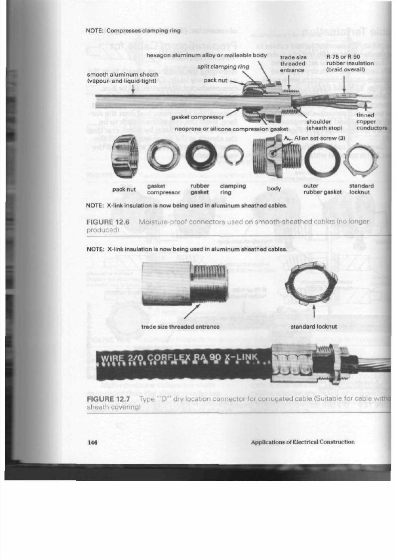
8/19/2019 Applications Electrical
http://slidepdf.com/reader/full/applications-electrical 151/447
N O T E :
Compresses clamping r ing
hexagon a luminum al loy or mal leable body
spl i t c lamping r ing
smo o th a lu m in u m sh e ath
(vapour- and liquid-t ig ht) pack nut
\
trade size
threaded
entrance
R-75 or R-90
rubber insulation
(braid overall)
gasket compressor
t inned
shoulder copper
neoprene or sil icone com pression gasket (sheath stop) conduc
I A c.
Alle n set-screw (3)
.
gasket rubber cla mp ing
p a c n u
com pressor gasket ring
body
outer standard
rubber gasket locknut
N O T E : X-link insulation is now being used in aluminum sheathed cables.
FIGURE 12.6 Moisture-proof connec tors used on smo oth-shea thed cables (no longer
produced)
N O T E :
X-link insulation is now being used in aluminum sheathed cables.
^n^^Ji
trade size threade d entrance standard locknut
WH»K?.9Pa
F
.tWJP
W
*-.
u
*
K
.
FIGURE 12.7 Type " D " dry location connector for corrugated cable (Suitable for cable w
sheath covering)
146
Applications of Electrical Construction
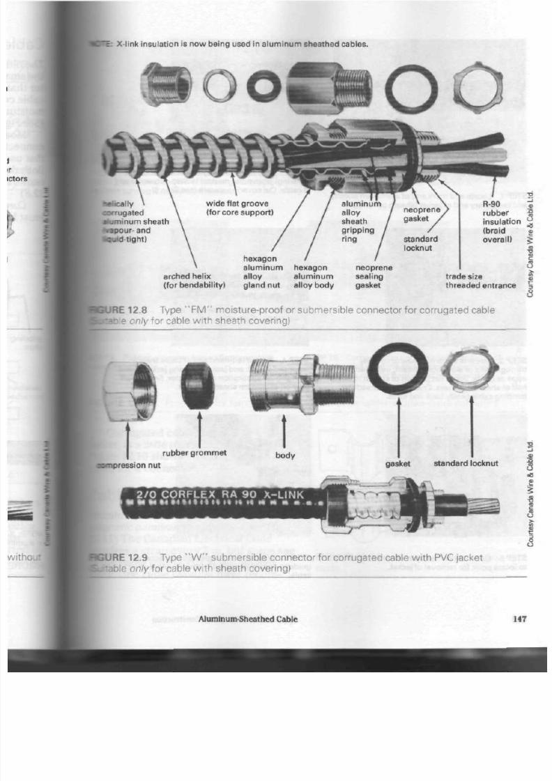
8/19/2019 Applications Electrical
http://slidepdf.com/reader/full/applications-electrical 152/447
c X-link insulation is now being used in aluminum sheathed cables.
helically
corrugated
aluminum sheath
toapour- and
fcau id-tight)
arched helix
(for bendability)
hexagon
a l u m i n u m
alloy
gland nut
hexagon
a l u m i n u m
alloy body
neoprene
sealing
gasket
R-90
rubber
insulation
(braid
overall)
trade size
threaded entrance
RE 12.8 Ty pe " F M " mois t ure- proof or s ubm ers ib le c onnec t or f or c or rugat ed c able
only for cable wi th sheath cover ing)
rubber grommet
compression nut
2 / 0 C O R F L E X RA 9 0 X - L I N K
m m * * • « * • • « « < t • * > t u » « « • M * • • •
JRE 12.9 T y p e " W " s u b m e r s i b le c o n n e c t o r f o r c o r r u g a t e d c a b le with PVC jac k et
itable only for cable wi th sheath cover ing)
Aluminum-Sheathed Cable
14

8/19/2019 Applications Electrical
http://slidepdf.com/reader/full/applications-electrical 153/447
P O I N T M A R K E D
IN FIG 1 I
C O N N E C T O R A P P L I E D
T H I S E N D
STEP 1. Locate and mark end of a lum inum sheath
and temp orary end of jacket (sheath cove r ing) .
ST EP 2, S tr ip off sho rt leng th of jacket (sheath
cover ing) f rom point marked in Step 1 t owar ds end
of cable. Cut covering square (see Step 6).
REMOVE
THIS END
C O N N E C T O R A P P L I E D
T H I S E N D
STEP 3. Use f ine tooth hacksaw to cut fu l ly
through hel ix of a luminum sheath, us ing jacket
edge as guide. Score f lat por t ion of sheath to a bout
half of sheath thickness. Crack scored sheath by
bending cable gent ly back and for th.
STE P 4. P ull off left-hand end of cable sheath
(exposed sheath and jacket), leaving jacketed end
(at r ight) for app licat ion of connec tor. S mo oth o ff
burr on aluminum sheath th is end.
STE P 5. Use mark on hexagon of connector bo dy
to locate point for removal of jacket.
STEP 6. Wrap piece of paper around jacket as
guide to ensure jacket cut is square with axis of
cable.
148
Applications of Electrical Construction

8/19/2019 Applications Electrical
http://slidepdf.com/reader/full/applications-electrical 154/447
R U BB E R G R O M M E T
Jacket removed and compon ents of con-
faced as show n. Wet rubber grom me t to
(turning it on jacket of sheath.
BODY OF CONNECTOR
STEP 8. Body of connector turned f i rm ly by hand
onto a lum inum sheath. Do not use wrench.
s
=8
9>
• Rubber grom me t turned f i rmly against STEP 1 0. Compressionnutthreaded onto body of
connector. connector. Use wrenche and compres s grom met
until it bulges slightly from under compression
nut.
12.10 P rocedure for terminating corrugated cable w ith moisture-proof connector
Corrugated cab le, with its PVC
t.
is a little m ore difficult to ha nd le.
12.10
shows how to prepare this
I
for a con necto r.
lie Supports
inum-sheathed
cable requires
non-
tetic aluminum
su pp ort s. (See Fig.
II)
The Canad ian E lectrical Code
?s a strap every 2 m, but som e sag
I cable may occur in the smaller
5.
One cable manufacturer recom-
O
XJT
Q
FIGURE 12.11 Aluminum clips for A /S
cable
Aluminum-Sh eathed Cable 149

8/19/2019 Applications Electrical
http://slidepdf.com/reader/full/applications-electrical 155/447
m ot or w i r ing
mends a s t rap every 1 m to 2 m on
cables up to 3 cm in diameter. In m any
industrial installations, m ulti-conduc
cab les are laid in a trough or rack
designed
for
this purpose. Figure 12.1
show s typical cable installations.
pulp and paper mil
FIGURE 12.12 Cable applications
F o r R e v i e v
1.
What are th e two main typ es of
aluminum-sheathed cable?
2. Which aluminum-sheathed cable
is easier to bend
in
large sizes?
3. What jacket material is used for
corrosion-resistant cable?
4. What is the most common volta
rating for aluminum -sheathed
cable?
5. W hat is th e maximum temperatu
rating
for
the cond uctors
in alum
num-sheathed cable?
6. Why
is it
more econom ical to
run
single-conductor cab les, rather
than one multi-conductor cable'
1
7. Explain in your own words how
sheath currents are produced in
aluminum-sheathed cable install
tions.
8. Why are there no sheath curren
in multi-conductor cable syste
9. Magnetic materials must
not be
used to support or terminate sirv
gle-conductor
cables. Explain.
10. Describe briefly how to remove
the aluminum sheath from
a ca
that is to be terminated in a dis
bution panel.
11. W hat spacing is required by th e
Canadian Electrical Code for
straps supporting aluminum-
sheathed cable?
ISO
App lications of Electrical C onstruction
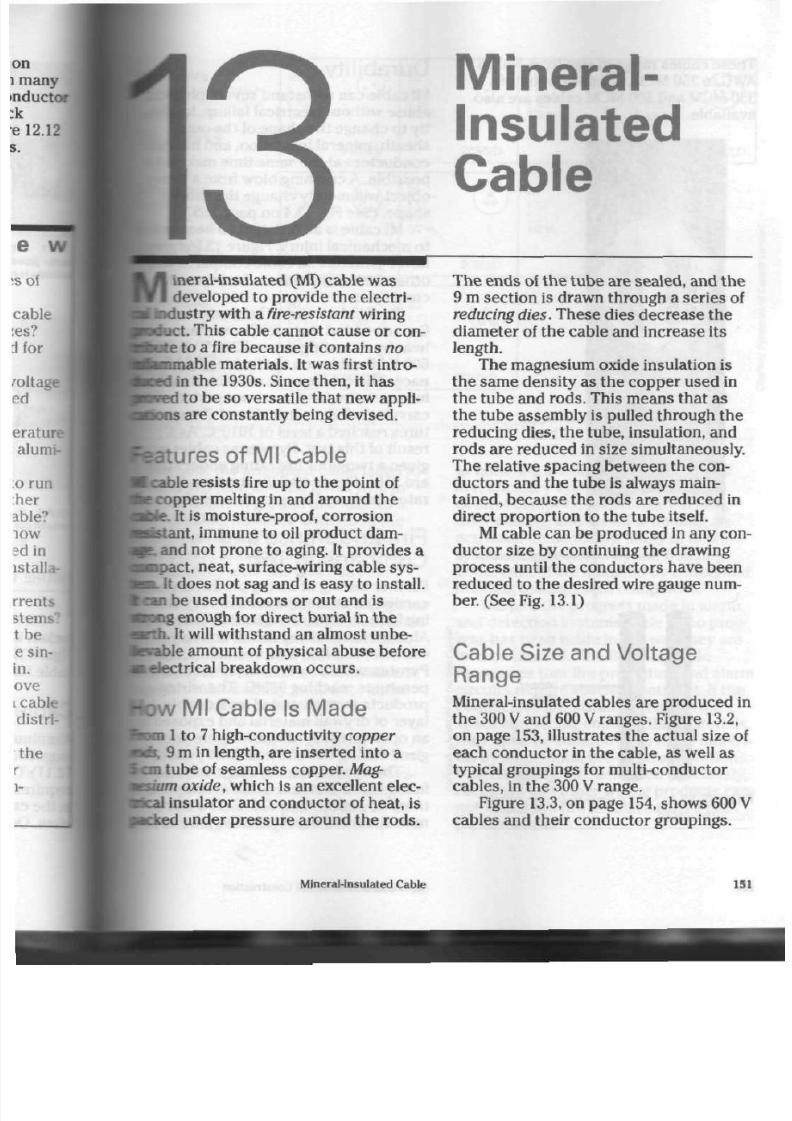
8/19/2019 Applications Electrical
http://slidepdf.com/reader/full/applications-electrical 156/447
ineral-insulated (MI) cable was
developed to provide the electri-
tadustry with a fire-resistant wiring
:t. This cable cannot ca use or con-
l a t e to a fire bec aus e it contain s no
tamable
m ater ials. It was first intro-
d in th e 1930s. Since the n, it ha s
I
to be so versatile that new appli-
; are constantly being devised.
rturesof Ml Cable
[cable resists fire up to the point of
f copper melting in and aroun d th e
He. It is moisture-proof, corrosion
•stant, immune to oil product dam -
9? .
and not pron e to aging. It pro vide s a
mpact, neat, surface-wiring cable sys-
•L It doe s not sa g and is eas y to install.
be used indoors or out and is
long enough for direc t burial in th e
•rth. It will withstand an almo st u nbe
arable
amo unt of physical ab use before
i
electrical breakdow n o ccu rs.
D W
Ml C able Is M ade
1 to 7 high-conductivity
copper
9 m in length, are inserte d into a
i tube of seam less copper.
Mag-
<im
oxide, w hich is an excellent elec-
insulator and conductor of heat, is
eked under pressure around the rods.
Mineral-
Insulated
Cable
The end s of the tube are sealed, and the
9 m section is drawn throu gh a series of
reducing
dies. These dies decrease the
diameter of the cable and increase its
length.
The magnesium oxide insulation is
the sam e density as the coppe r used in
the tube and rods. This m eans that a s
the tube assem bly is pulled through the
reducing dies, the tube , insulation, and
rods are reduced in size simultaneously.
The relative spacing between t he con
ducto rs and th e tube is always main
tained, beca use the rods are reduced in
direct proportion to th e tube itself.
MI
cable can be produ ced in any con
duc tor size by continuing the drawing
process until the conductors have been
reduced to the desired w ire gauge num
ber. (See Fig. 13.1)
Cable Size and Voltage
Range
Mineral-insulated cables are produced in
the 300
V
and 600
V
ra ng es. Figure 13.2,
on pag e 153, illustrates the a ctual size of
each con ducto r in the cable, as well as
typical groupings for multi-conductor
cables , in the 300
V
range.
Figure 13.3, on page
154,
shows 600 V
cables and their conductor groupings.
Mineral-Insulated Cable
151

8/19/2019 Applications Electrical
http://slidepdf.com/reader/full/applications-electrical 157/447
Th ese ca bles range in size from No. 16
AWG to 250 MCM. Single-conductor,
350 MCM and 500 MCM cables are also
available.
copper
tube
•
m agne s ium -ox ide
insulat ion
•
copper
rods
E
•J
FIGURE 13.1
insulated cable
Cutaway view of mineral-
Durabil ity
MI
cable can withstand severe
phys
abuse without electrical failure. Its a
ity to change the sh ap e of the outer
sheath, mineral insulation, and
in te
conductors at the same time makes
possible.
A
crushing blow from a h e
object will merely change the cable'
sh ap e. (See Fig. 13.4 on page 155.)
MI cable is as resistant to heat a
to mechanical injury. Figure 13.5
sh
how Pyrotenax MI cable compares w
other wiring systems under severe h
conditions.
The Underwriters' Laboratories
Canada tested th e cable's resistance
heat by mounting several 300 V and
600
V MI
cab les on the inside of a fu
nace. The cables w ere subjected to
furnace's fire for a two-hour period
carrying a full electrical load. Temp
tu re s re ac he d a level of 1010°C. As a
result of this test, Pyrotenax cables
given a two-hour fire rating under st
ard
S101.
Figure 13.6 illustrates a fire
rated cable and its attach ed label.
Fire E ndurance and
Comparison Test
Further testing of wiring products w
carried on at the Warnock Hersey
T
ing Labs in Vancouver, British Colum
Aluminum-sheathed cable, armoure
cable, 90°C X-link wire in cond uit, an
Pyrotenax cable were subjected t o
peratures reaching
939°C.
The wirin
produ cts were mounted on a double
layer of drywall m aterial and exp ose
an o pen furnace. All cables were
en
gized during the
one-hour
test perio
The conventional wiring produ c
failed within the first 3 min at
temp
tures n o higher than 316°C. The alu
num-sheathed cable failed to ground
152
Applications of Electrical Con struction
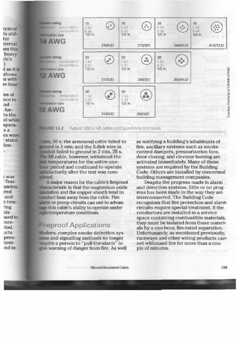
8/19/2019 Applications Electrical
http://slidepdf.com/reader/full/applications-electrical 158/447
I
rat ing
ims/1000ft
ohms/1000
m
i size
A W G
rat ing
nms/1000ft .
ohms/1000 m
i
size
A W G
[ ra t ing
hms/1000ft
Ohms/1000
m
i size
A W G
15
2.58
8.46
1/2 in.
0
240/2/D
15
2.58
8.46
1/2 in.
©
273/3/D
15
2.58
8.46
1/2 in.
©
344/4/LD
15
2.58
8 4 6
3/4 in.
/ • • \
1 " • • J
418/7/LD
20
1.62
5.31
1/2 in.
30
1
02
3 35
1/2 in.
©
273/2/D
20
1.62
5.31
1/2 in.
©
309/3/D
20
1.62
5.31
1/2 in.
©
319/2/D
3 0
1.02
3. 35
1/2 in.
. • •
355/3/D
3 9 3 / 4 / L D
1 3 . 2 T y p i c a l 30 0 V M l c a b l e c o n f i g u r a t i o n s and s i z e s
50 s; th e arm ou red cable failed
to
I in 3 m in; and t he X-Iink wire in
ait failed
to
ground
in
2 m in, 25
s.
j MI cab le, however, withsto od
the
:
temperatures for the entire one-
m
period and continued
to
operate
sfactorily after the test was com
pleted.
A major reason for the cable's fireproof
iarac teristic is that the magnesium oxide
•ulation
and the copper sheath tend to
•duct hea t away from t he cable. Fire
tern or pump circuits can use to advan
ce this cable's ability to op erate und er
Ji-temperature conditions.
reproof Applicat ions
idem,
complex smoke detection sys-
D S
and signalling methods no longer
iire a person to "pull-the-alarm" to
•e
warning of da ng er from fire. As well
as notifying
a
building's inh abita nts of
fire, ancillary system s such as smoke
control dampers, pressurization fans,
doo r closing, and elevator hom ing are
activated immediately. Many of these
systems are required by the Building
Code. Othe rs are installed by con cerned
building management companies.
Despite the progress m ade in alarm
and dete ction sy stem s, little or no prog
ress has been m ade in the way they are
interconnected. The Building Code
recognizes that fire protection and alarm
circuits require special treatm ent. If th e
conductors are installed
in a
service
space containing combustible materials,
they must
be
isolated from th es e ma teri
als by a one-hour, fire-rated sep aratio n.
Unfortunately, as mentioned previously,
raceways and other wiring products can
not withstand fire for more than a cou
ple of minutes.
MineraHnsulated Cable 15S

8/19/2019 Applications Electrical
http://slidepdf.com/reader/full/applications-electrical 159/447
Resistance ohms/1000
ft
ohms/1000 m
Term ination size
16 AWG
Current rat ing
Resista nce ohms/1000 ft.
ohms/1000 m
Termination size
14 AWG
Current rating
Resistance
ohms/ioooft
ohms/1000
m
Termination size
12
AWG
Current rating
Resistance ohms/1000 ft.
ohms/1000 m
Termination size
10 AWG
Current rating
Resistance
ohms/ioooft
ohms/1000
m
Te rmination size
8
AWG
Current rating
Resistance ohms/1000 ft.
ohms/1000 m
Termination size
6 AWG
Current rating
Resistance
ohms/i 000 ft
ohms/1000
m
Termination size
4
AWG
Current rat ing
Resistance
ohms/1000 ft
ohms/1000 m
Te rmination size
Current rat ing
Resistance ohms/1000 ft.
ohms/1000 m
Te rmination size
4.094
13.43
1/2 in.
O
215/1
4.094
13.43
1/2 in.
©
340/2
4 094
13.43
1/2 in.
©
355/3
4.094
13.43
3/4 in.
©
387/4
4.094
13.43
3/4 in.
4
20
2.58 Q
8 4 6
1/2 in.
230/1
15
2.58 (77)
8.46
*—'
1/2 in.
371/2
15 ^
258 (£\
8.46
^zy
1/2 in.
387/3
15
III
(3
3/4 in.
418/4
12
2.58
(
8.46
/4 in.
4
25
1.62 0
5 31
1/2 in.
246/1
20
1.62
5.31
1/2
in
©
402/2
20
1.62
5.31
1/2
in
©
434/3
20 ^-~.
IS ©
3/4 in.
465/4
16
1.62
5 3 1
3/4 in.
®
5
4 0
1.02 (S)
3 3 5
W
1/2 in.
277/1
30 _^^
1.02 ( 1 )
3.35 \ L x
3/4 in.
449/2
3 0 _ ^
iS ©
3/4 in.
480/3
30
/
^ -
x
a ®
/4 in.
527/4
24
1.02
3.35
1 in.
^
(
6
70
0.641
2.1
1/2 in.
®
309/1
50
0.64
2
3/4 in.
641 f~»\
512/2
50
0.641
2 1
3/4 in.
543/3
40
0.641
2.1
3/4 in.
590/4
100
0 4 0 3
1.32
1/2 in.
®
340/1
70
0.403
1.32
3/4 in.
590/2
70
0.403
1.32
3/4 in.
• • ;
621/3
684/4
135
0.253
0,83
1/2 in.
®
402/1
684/2
90
/
—
N
0 253 I # \
0
83 \%%)
1 in.
V /
730/3
3
AWG
2
AWG
1
AWG 1/0 AWG 2/0
155
0.201
0.66
1/2 in.
< § >
434/1
180
0.159
0.52
3/4 in.
465/1
210
0.126
0 41
3/4 in.
®
496/1
245
0 100
0.33
3/4 in.
543/1
285
0.0795
0.26
3/4 in.
5
3 / 0 A W G
ir(§)
3/4 in. ^ - ^
637/1
4 / 0 A W G
385
/ ^ \
0.0500/^AA
016 \ W /
1 in.
v
—
'
699/1
2 5 0 M C M
425
/ ^ \
0 0431/ f lA)
0.14
^
746/1
FIGURE 13.3 Typical 600 V M l cable configurations and sizes
(The ratings shown for
sin
conductor cables are thos
design ated by the C anadia
E lectrical C ode, Pan 1, for
cables in free air.)
Screw-on seals for this
cable range.
154 Applications of Electrical Construction
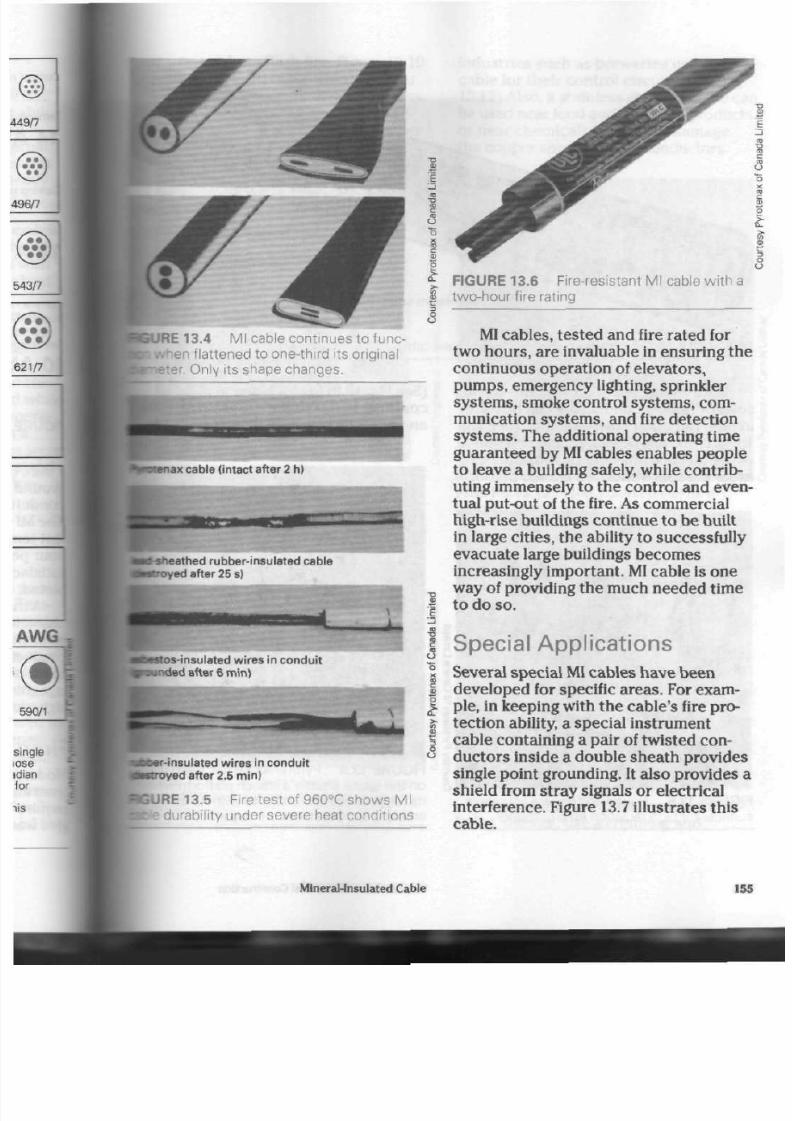
8/19/2019 Applications Electrical
http://slidepdf.com/reader/full/applications-electrical 160/447
RE 13.4 M l cable continues to func-
n flattened to one-third its original
iter.
O nly its shape changes.
tenax
cable (intact after 2 h)
sneathed rubber-insulated cable
foyed
after 25 s)
s
£
2
< 3
FIGURE 13.6 Fire-resistant
two-hour fire rating
cable w ith a
MI cables, tested and fire rated for
two hours, are invaluable in ensuring the
continuous operation of elevators,
pumps, emergency lighting, sprinkler
systems, smoke control systems, com
munication systems, and fire detection
systems. The additional operating time
guaranteed by
MI
cables enables people
to leave a building safely, while contrib
uting immensely to the control and even
tual put-out of the fire. As commercial
high-rise buildings continue to be built
in large cities, the ability to successfully
evacuate large buildings becom es
increasingly important. MI cable is one
way of providing the much needed time
to do so.
estos-insulated
wires in conduit
Minded after 6 mini
S
•r-insulated w i r es in c ond u i t
royed
after
2.5 min)
SURE 13.5 Fire test of960°C shows Ml
te durability under severe heat conditions
Special Applicat ions
Several special MI cables have been
developed for specific areas. For exam
ple, in keeping with the cable's fire pro
tection ability, a special instrumentcable containing a pair of twisted con
ducto rs inside a double sheath provides
single point grounding. It also provides a
shield from stray signals or electrical
interference. Figure 13.7 illustrates this
cable.
MlneraJ-lnsulated Cable 155
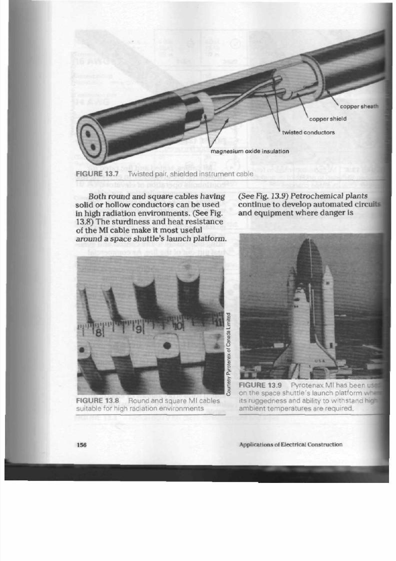
8/19/2019 Applications Electrical
http://slidepdf.com/reader/full/applications-electrical 161/447
copper sheat
copper shield
twisted conductors
m agnes ium ox ide ins u la t ion
FIGURE 13.7 Twisted pair, shielded instrument cable
Both round and square cables having
solid or hollow conductors can be used
in high radiation environm ents. (See Fig.
13.8) The sturdiness and heat resistance
of the Ml cable make it most useful
around a space shu ttle's launch platform.
(See Fig. 13.9) Petrochemical plants
continue to develop automated circuit
and equipment where danger is
Applications
of
Electrical Construction

8/19/2019 Applications Electrical
http://slidepdf.com/reader/full/applications-electrical 162/447
present from flash fire. Figure 13.10
:
a typical
MI
cable installation in
area.
Large-scale mining operations
•provide a challenge for this versa-
woduct. (See Fig. 13.11) Many oth er
PURE 13.10 M l cable is used in the petro-
^ B a l industry.
^ • R E 13.11 Ml was chosen for its dura-
id fire resistance in this large-scale
phg
ope ration.
industries such as breweries use MI
cab le for their c ontro l circ uits. (See Fig.
13.12) Also, a stainles s stee l MI cable can
be used near food and beverage products
or near chemicals that could dam age
the copp er sheath and its conduc tors.
Mineral-Insulated Cable
FIGURE 13.12 This control panel for a
brewery bottling plant uses M l cable.
Cable Termination
Prepackaged termination kits are used
to connect
MI
cable to boxes, cabinets ,
and fittings. (See Fig. 13.13) Remove the
copper sheath with a stripping tool.
Place
a
gland connector on the cable just
before threading the self-tapping pot on
to the outer sheath. Press plastic sealing
com pound into the pot . Make sure yo ur
hands are clean so that no metal parti
cles are pressed in to th e sealing com
pound. A short circuit will likely occu r if
metal particles of any kind are allowed
to enter the pot.
Next, install the preasse m bled insu
lating
sleeves.
Use a crimping and
157
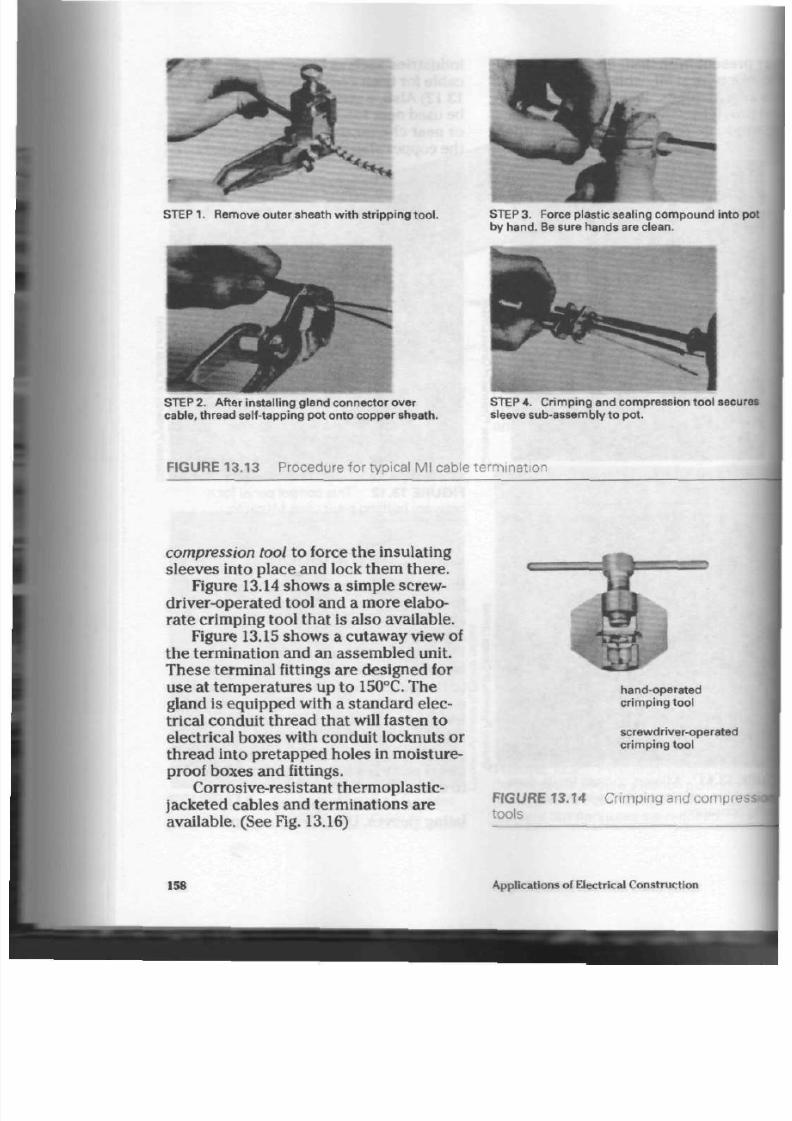
8/19/2019 Applications Electrical
http://slidepdf.com/reader/full/applications-electrical 163/447
STEP
1.
Remove outer sheath with stripping
tool.
STE P 3. Force plastic sealing compoun d into po
by hand. Be sure hands are clean.
STEP
2.
A fter installing gland connector over
cable,
thread self-tapping pot onto copper sheath.
STEP 4 . C rimping and compression tool secure
sleeve sub-assembly to pot.
FIGURE 13 .13 P rocedure for typical Ml cable term inat io n
compression tool
to force the insulating
sleeves into place and lock them there.
Figure 13.14 show s a simple
screw
driver-operated tool and a m ore elabo
rate crimping tool tha t is also available.
Figure 13.15 shows a cutaway view of
the termination and an assembled unit.
These terminal fittings are designed for
use at temperatures up to 150°C. The
gland is equipped with a standard elec
trical conduit thread tha t will fasten to
electrical boxes with conduit
Iocknuts
or
thread into pretapped holes in moisture-
proof boxes and fittings.
Corrosive-resistant thermoplastic-
jacketed cab les and terminations are
available.
(See
Fig. 13.16)
158
hand-operated
crimping tool
screwdriver-operated
crimping tool
FIGURE 13 .14 C r i m p i n g a n d c o m p r e s s
tools
Applications of Electrical Construction

8/19/2019 Applications Electrical
http://slidepdf.com/reader/full/applications-electrical 164/447
0)
c
c
o
o
"D
c
JO
brass
gland nut
brass
c om pr es s ion
r ing
brass
gland
body
tapered pipe
thread
brass pot cuts
own thread as
it screws onto
cable sheath
seal ing
c o m p o u n d
anchor ing
wedge
secur ing
sleeving
into cap
insulat ing cap
insulat ing
sleeve
JRE 13.15
A n Ml cable termination and
3d unit (cutaway v iew)
All cable terminations should be
Bcked with an insulation tester. This
^-resistance measuring instrument
I
apply approximately
500 V
to the
••ination and indicate whether or not
is safe for use.
o
a.
c
o
0)
o
CO
o
"5
o
FIGURE 13.16 A thermoplastic-jacketed
cable termination for corrosive areas
MI cable can be formed into a bend
having a radius no less than six times th
diameter of the cable being bent, with
out placing undue stre ss on it.
Multiple runs of Ml cable require
care and precision in planning. (See Figs
13.17 and 13.18)
ble
Installation
cable is supported by copper straps
ated every 1 m to 2 m throughout th e
i. A wooden block and hammer are
ed to straighten any irregularities in
3\e.
FIGURE 13.17 Ml cable mu ltiple runs
Mineral-Insulated Cable 159

8/19/2019 Applications Electrical
http://slidepdf.com/reader/full/applications-electrical 165/447
Sheath Currents
Induced currents can flow in the outer
sheaths of single-conductor cables in
alternating current circuits. (See Chap
ter
12)
The electromagnetic fields sur
rounding nearby cables cause them.
Since heat generated by sheath currents
does not affect MI cables much, these
cables do not need to be spaced apart.
They can be grouped together under a
common strap. (See Fig. 13.18)
Cables carrying in excess of 200 A
must be fastened to a nonmagnetic plate
at both ends of the cable, prior to secur
ing to a box or panel. Doing so elim
inates heat induction which could dam
age the box and its contents.
General Purpose
Applicat ions
The versatile MI cable is used for many
purposes and in many situations besides
fire protection and warning systems.
Commercial buildings, factories, houses,
and apartments, as well as processing
plants, and railway and subway system s,
make use of this cable. It is used for elec
tric heating of driveways and ste ps to
aid in snow removal and of water p ipes
to provide protection from frost. It can
also eliminate solidification of waxes
FIGURE 13.18 S ingle-conductor M l ca
entering distribution panel
and other materials in oil refinery pir.
and systems.
In addition to these uses, MI cable
found in communication and transmis
sion systems and has particular applk
tion in all kinds of marine vessels and
hazardous areas that contain dust,
explosive vapours , or liquids. Figure
13.19 shows MI cable applications.
160
Applications of Electrical Construction
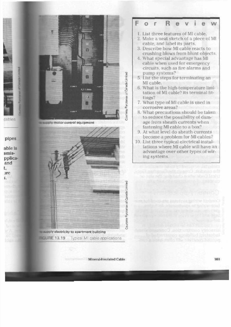
8/19/2019 Applications Electrical
http://slidepdf.com/reader/full/applications-electrical 166/447
S
F o r R e v i e w
1. List three features of MI cable.
2. Make a neat sk etch of a piec e of MI
cable, and label its parts.
3.
D escribe how MI cable reacts to
crushing blows from blunt objects.
4. What special advantage has MI
cable when used for emergency
circuits, such as fire alarms and
pump sys tems?
5. List the steps for terminating an
MI
cable.
6. What is the high-temperature limi
tation of
MI
cable? its term inal fit
tings?
7. What type of MI cab le is used in
corrosive areas?
8. What precautions should be taken
to red uc e the po ssibility of dam
age from sheath currents when
fastening MI cab le to a box?
9. At wha t level do s hea th cu rren ts
beco m e a problem for MI cables?
10. List three typical electrical instal
lations where
MI
ca ble will have an
adv antage over othe r types of wir
ing systems.
ply electr icity to apartment building
JRE 13.19 Typical MI cable applications
Mineral-Insulated Cable
161

8/19/2019 Applications Electrical
http://slidepdf.com/reader/full/applications-electrical 167/447
A
conduit wiring system offers a
mechanical protection to electrical
circuits that is rare with other wiring
methods. Voltage in a conduit system is
limited only by the insulation on the
conduc tors within the system. Metallic
conduits provide a high degree of fire
protection, as well as the ability to safely
contain overloaded or short-circuited
conductors tha t could cause or contrib
ute to a fire.
Unlike any other wiring method, con
duit allows the conductors within the
system to be removed easily, without dis
mantling the system . A change in circuit
design or equipment will often require
conductors of a different
size,
colour,
material, or quantity to be installed in
the conduit. Consult the Canadian Elec
trical Code when changing the size or
quantity of conductors in a conduit.
Conduit Appl icat ions
Conduit wiring system s are used for sur
face wiring in apartm ents , factories,
garages, warehouses, and public build
ings and for service entrance equipment
for a house.
Conduit can be buried directly in
masonry construction. Commercial and
industrial buildings constructed of
poured concrete will often have a con-
Conduit
Wir ing
duit wiring system installed before the
concrete is poured. Conductors to be
installed under ground can be ade
quately p rotected by a conduit syste
When installed properly, conduit i
both water- and vapour-tight. Hazardc
areas , where explosive liquids, gases,
dusts are present, can be wired safely
with conduit and electrical fittings
approved for the purpose. Plastic-cc
conduits a re available for use in areas
where corrosive materials are presen
Motors and similar equipment subjec
vibration or movement can be con
nected with flexible conduit. Liquid-1
dust-tight varieties of flexible conduit
are also available.
Conduit Sizes
Conduit is usually produced in 3 m
lengths. This length, regardless of du
eter, provides an easy-to-estimate, pr
tical unit for installation and allows f
ease of bending and handling. Under
normal conditions, these lengths canl
quickly assembled into a continuous
run.
The second important dimension?
the conduit is internal diameter. This
measurement determines the quantity
and size of the conductors that can
safely installed in the conduit. Sectiod
162 Ap plications of Electrical Co nstru ction

8/19/2019 Applications Electrical
http://slidepdf.com/reader/full/applications-electrical 168/447
I the C anadian E lectrical Cod e lists gen
ii installation ru les and allowab le con-
hit capacities.
Conduit is av ailable in th e following
fe sizes, as determined by the inter-
diameter, in millimetres: 13,20,25,
138,
51, 64,
76,89,102,127,
and 152.
ypes of Conduit
: are several typ es of condu it. This
lapter d iscu sses rigid (thickwall), EMT
binwall), rigid a lum inum , rigid PVC,
tarible, and PVC flexible (liquid-tigh t)
iduit.
d Conduit
1, or
thickwall,
conduit is produced
aluminum or steel. This thickwall type
ides th e greatest am oun t of
hanical
protection to co nd uc tors. It
ivailable
with a cho ice of e xterna l
Batings, such as electroplating, baked-
i enamel, or polyvinylchloride, to
jce th e damag ing effect of corro sive
licals in cer tain installation s. (See
14.1)
Rigid conduit must be supported by
)ved
strap s, cl ips, or hang ers at
lar
intervals . These sup po rts mu st
i located in acco rdan ce w ith Section 12
f the C anadian E lectrical Code, Pa rt 1.
tion 12 outlines interva ls as follows:
13 mm and 20 mm cond uit : Not
aceeding 1.5 m intervals;
25 mm and 32 mm c ond uit: Not
Breeding
2 m intervals;
38 mm a nd larger: Not exceeding 3 m
•terva l s .
Normal prac tice is to locate a sup
port within 75 cm of a box or ca bin et.
The inside of steel co ndu it is often
a>ated with an insulating paint or
mxrnish to ease the installation of con
ductors, insulate damaged conductors
r igid steel conduit (electroplated f inish)
RlSss
steel th inw al l (EMT) con duit
(elect roplated f in ish)
rigid steel conduit (baked enamel f inish)
r ig id aluminum conduit
r igid steel conduit (PVC-jacketed)
PVC -jacketed th inwal l (E MT) condu it
r ig id PVC c onduit
FIGURE 14.1 E lectrical cond uit raceways
Conduit Wiring
16

8/19/2019 Applications Electrical
http://slidepdf.com/reader/full/applications-electrical 169/447
from the metal wall of the cond uit, a nd
prevent internal conduit rusting.
Lengths of rigid conduit mu st b e
threaded
at each end for connection to
coup lings, boxe s, or fittings.
Threading Rigid Conduit.
The best
method for holding conduit securely for
threadin g is in a pipe vise. (See Fig. 14.2)
For the best straight cut, hold th e
hacksaw at an angle of app roxim ately
45° to t h e ho rizontal. Figure 14.2 sho w s
the hacksaw being drawn back with one
hand, so that th e pipe vise would not be
hidden. In actual pra ctice, the second
hand should grip the front portion of the
saw. A more secure grip and a straighter
cut would result.
.cutting
wheels
. rollers
conduit
FIGURE 14.3 Pipe cutter
conduit
pipe
vise
hand reamer
FIGURE 14.4 Reaming conduit
FIGURE 14.2 C utting conduit w ith hacksaw
(Note: Hacksaw should have 24 teeth per
2.5cm.)
A pipe cutter is also e xcellent for p ro
ducing ne at cuts for thre adin g. (See Fig.
14.3) Using one , how ever, will neces si
tat e extensive reaming to the inside of
the conduit.
Whichever method is used to cut the
conduit, a sharp burr, cap able of damag
ing th e co nd ucto r insulation, will be pro
duced on the inside of the conduit. This
must be removed with a
round file
or
reamer. (See Fig. 14.4)
Reaming the pipe before threading is
best , because some conduit reamers
expand th e ends of newly thread ed cc
duits. An expa nd ed edge, flared like a
bugle, makes starting th e threade d
co»
duit fitting on t o th e new threa d difficu
The actual thread is cut into the
pi
pared end of the conduit by a
stock
ar
die set. (See Fig. 14.5) At one time,
elec
trical stocks and d ies cut parallel
thre ads . Modern threading tools pro
duce tapered threads similar to those
used with water pressure systems. (Se
Figs. 14.6 and 14.7) Th ese t oo ls allow
cond uit fittings to be installed secur
on the new thread.
Cut sufficient thread into the cor
to completely engage the threads a\
ble on the conduit fitting. Doing so
164
App lications of Electrical Construction

8/19/2019 Applications Electrical
http://slidepdf.com/reader/full/applications-electrical 170/447
stock
ratchet
knob
squirt can for
cutting lubricant
IRE 14.5 C ut t ing thread on r ig id cond ui t
IE 14.6 P arallel thre ad
IRE 14.7 Tapered thread
provides the greatest mechanical secu
rity and ground continuity.
Application of a
cutting
liquid-
lubricant will ea se th e ph ysical effort
required to cut a threa d an d also extend
the life of the die's cutting edges. There
are severa l excellent thread ing lubri
cants , but oil or liquid soap can be used
when the proper lubricant is not at
han d. Th e simplest m etho d of applying
the cutting lubricant is with an oil squirt
can.
Bending Rigid Conduit. Installers nee d
many hours of practice to master the art
of bending and forming cond uit sy stem s.
Co nduits up to 25 mm internal diam
ete r are usually formed manually with
the h elp of a bending too l called a
hickey. (See Fig. 14.8) Hickeys a re av aila
ble in stand ard cond uit sizes; for b est
results, one of the p rop er size should be
used. Conduit of a larger trade size than
the hickey usually does not fit into the
bend ing tool. Smaller cond uit than the
tool is designed for often slips in th e
tool , producing kinks, inacc urate ben ds,
and /or bruises on the o perator .
Bends must be made without reduc
ing the internal diam eter of the cond uit.
A kink in th e b end will make installation
of conductors much more difficult and
1.2 m to 1.5 m handle
hickey
conduit
floor
4«
JJRE 14.8 Man ual con dui t bend er
Conduit Wiring

8/19/2019 Applications Electrical
http://slidepdf.com/reader/full/applications-electrical 171/447
might even dam age th e insulation. (See
Fig. 14.9) Figure 14.10 shows tw o safe
methods for using the manually oper
ated hickey.
Conduit is bent to go aro und
corne rs, pass over obstacles, or enter a
box at the prop er ang le. Figure
14.11
shows five bends and their uses.
The
offset
ben ds are used to enter a
box or cabin et and can be also used to
bring the cond uit from one level to
ano ther on any surface, such as a wall or
ceiling.
The
square saddle
is used to by-pass
protrusion s in a wall or to p ass ov er sev
eral con du its located side by side.
The 90° bend is used to go aroun d
inside corners. (An outside corner
requires a conduit fitting of the type
sho wn in Figure 14.27.)
Note: The saddle bend s take the
time to form. Care and pra ctice,
h
ever, will result in smo oth , well-
aligned bends.
The 45° offset bends are often us
to overcome ob structions in the pat
the conduit.
The operator who uses body we
rather than arm strength can greatly
reduce th e strain of bending c on du i
25 mm d iameter con duit can b e ver
resilient at times—a challenge to th
operator . Good technique and prac
are esse ntial. Th e em pha sis is on ma
ing the ben der to the con duit . Inste
however, often have to use a buildin
su pp or t b eam , a hole in a wall, or sc
othe r means when a bend m ust be
i
and no h ickey is available. Take grea
smooth bend
kink
SS
^
F IG URE 14 .9 S moo th condu i t bend s a re i mpor tan t . C ondu i t bends w i th k inks a re no t
suil
for conductor insta l la t ion.
Pull on hickey.
Place foot
against hi
Lean on hickey using body
weight to bend conduit
conduit
conduit flat on floor
mmmmfr- '
floor
Support base of hickey with foot
F IG UR E 14 .10 M eth ods fo r bend i ng cond u i t manua l ly
166
Applications of Electrical Con struction
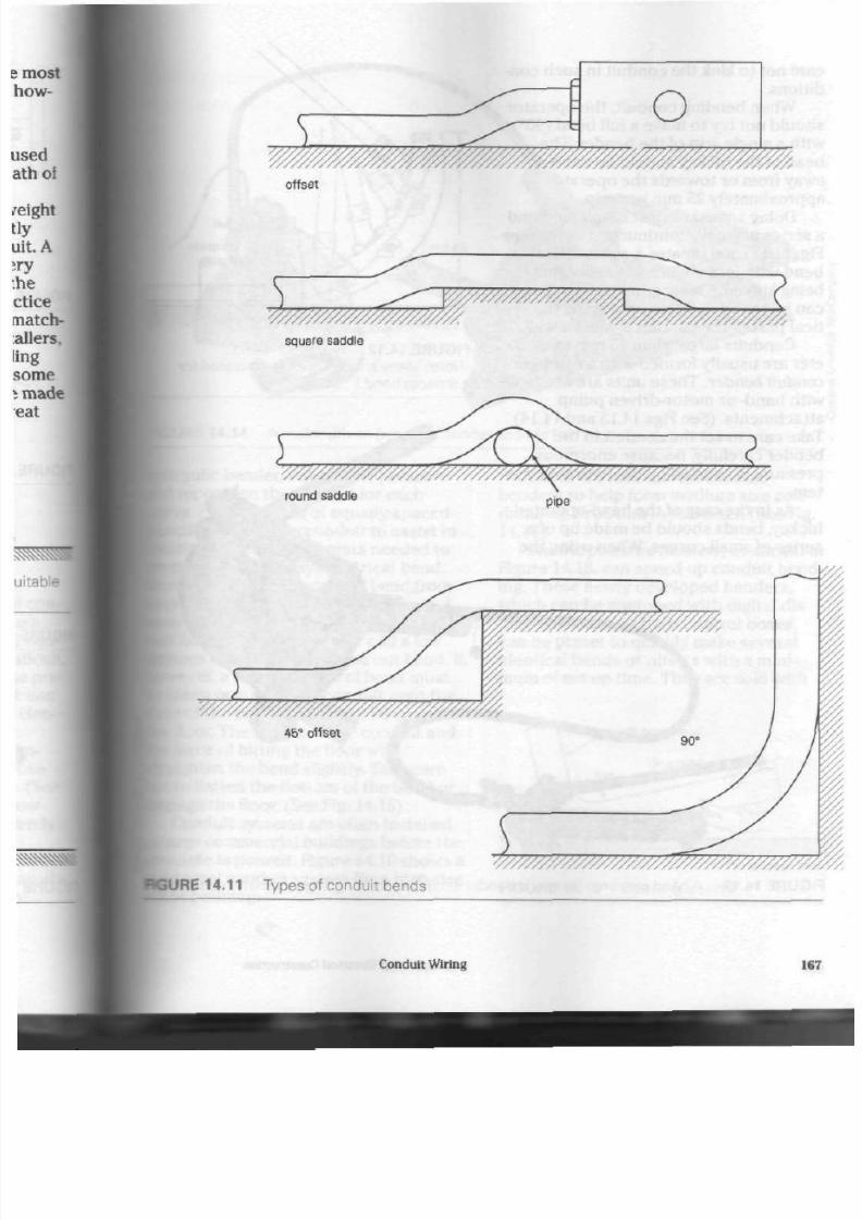
8/19/2019 Applications Electrical
http://slidepdf.com/reader/full/applications-electrical 172/447
offset
5
square saddle
^///////?////////M
pipe
^////////////////^////^//////////////////^
JURE 14.11 Types of conduit bends
Conduit Wiring
167

8/19/2019 Applications Electrical
http://slidepdf.com/reader/full/applications-electrical 173/447
care not to kink the co ndu it in suc h con
ditions.
When bending conduit , the ope rator
should not try to make a full bend (90°)
with a single grip of the ben der. Th e
head of the hickey should be moved
away from or towards the operator
approxim ately 25 mm per grip.
Doing so makes the com pleted bend
a series of small, con tinuou s cu rve s (see
Fig. 14.12) and cre ate s a sym m etrical
bend with less chan ce of th e co ndu it
being kinked. The ac curac y of the ben d
can be easily checked by placing the ver
tical part of the co ndu it aga inst a wall.
Conduits larger than 25 mm in diam
eter are usually formed with a
hydraulic
conduit bender. Th ese units are available
with hand- or motor-driven pump
att ac hm en ts. (See Figs 14.13 and 14.14)
Take care to set th e cond uit in the
ben der carefully, bec aus e en orm ous
pre ssure is exerted by the hydrau lic sys
tem.
As in the case of the han d-op erated
hickey, bends sho uld be ma de u p of a
series of small cu rve s. When using th e
FIGURE 14.12 Typical 90°bend
[Note: Many small curves are required fo
a smooth bend.)
FIGURE 14.13 A hand-operated hydraulic bender simp lifies form ing large diame ter
condu
168
App lications of Electrical Construc tion

8/19/2019 Applications Electrical
http://slidepdf.com/reader/full/applications-electrical 174/447
GURE 14.14 A motor-driven hydraulic bender speeds form ing large diameter conduits.
podi
ydraulic
bender, release the p ressu re
i reposition the conduit for each
te .
Place a serie s of equally spa ced
cil
marks on the conduit to as sist in
eating the pressure points needed to
luce a smo oth, symm etrical bend.
:e removing an exces s of ben d from
:
conduits is difficult, take care not
overbend.
It
is easier to place th e con-
back in the ben der and ad d a few
;s of bend than to take out bend. If,
>ever, a small amoun t of bend m ust
taken out, drop th e conduit onto the
[base of the ben d from abo ut 60 cm off
he
floor. The weight of the conduit and
he force of hitting the floor will
•raighten t he bend slightly. Take care
•ft to flatten the bottom of the bend or
Manage t he floor. (See Fig. 14.15)
Conduit system s are often installed
• large commercial buildings before the
concrete is po ure d. Figure 14.16 show s a
rtgid-steel cond uit sy stem for a high-rise
•nice building.
There are mechanical conduit
ben der s to help form medium size con
duits,
up to 38 mm in diame ter. (See Fig.
14.17)
Electric-powered benders, as shown i
Figure 14.18, can speed up conduit bend
ing. Th ese newly developed ben der s,
which can be equ ippe d with digital dis
play read-outs on their control boxes,
can be preset to quickly make several
identical be nd s or offsets with a mini
mum of set-up time. They are sold with
Shock will open bend.
. . .
N concrete floo
FIGURE 14.15 O pening a bend
Conduit Wiring
16

8/19/2019 Applications Electrical
http://slidepdf.com/reader/full/applications-electrical 175/447
FIGURE 14.16 Installing condu it before
pouring concrete
FIGURE 14.18 A n electric bending mac
all
forms of roller support and shoe
attachments included. They control
accuracy and consistency of their I
electronically.
Thinwal l Condui t
iu
lis
E
o
O
FIGURE 14.17
bender
Typical mechanical conduit
The proper name for thinwall condi
electrical metallic tubing (EMT). T
conduit does not provide the same
degree of mechanical protection as
conduit, but it has several importan
advantages.
EMT is made of lightweight, s
tubing, and so does not require as m
physical strength on the part of the
installer as does rigid conduit, when
assembling the conduit system. (See
14.19)
Also,
because of its lightweig
construction it is not practical to th
EMT. This feature alone saves much
170
Applications of Electrical Construction
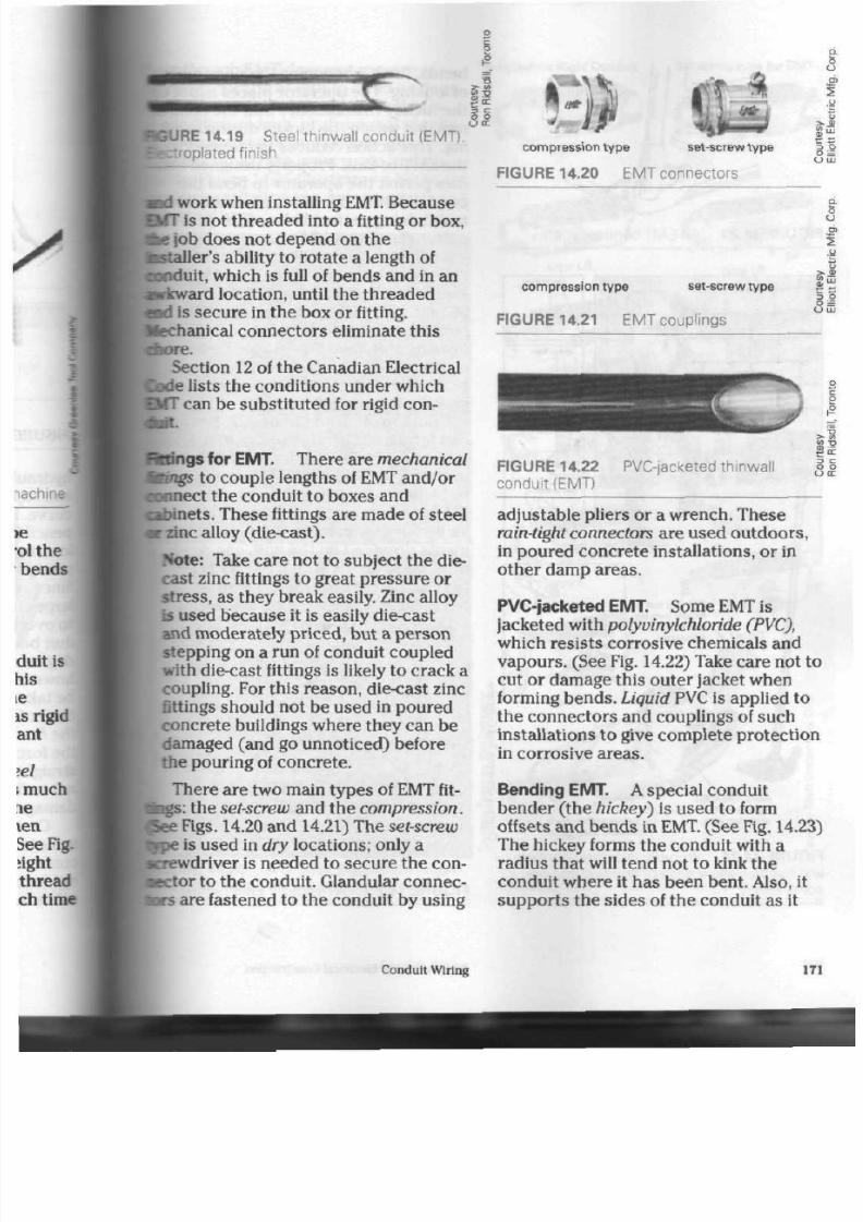
8/19/2019 Applications Electrical
http://slidepdf.com/reader/full/applications-electrical 176/447
GURE 14.19 S teel thinwall conduit (EMT ).
;plated finish
nd
work w hen installing EMT. Because
IIT is not th rea de d into a fitting o r box,
fee job does not depend o n the
•Btaller's ability to r ota te a length of
conduit, which is full of bends and in an
wkward location, until the threa ded
n d is sec ure in the box or fitting.
Mechanical connectors eliminate this
bore .
Section 12 of the Ca nadian Electrical
ode lists the co ndition s und er wh ich
MT
can be substituted for rigid con-
r.:.t.
•Kings for EMT. Th ere ar e m echanical
Mings to co uple leng ths of
EMT
and /or
connect the conduit to boxes and
Bfoinets. These fittings are made of steel
r zinc alloy (d ie-ca st).
Note: Take care not to subject the die-
cast zinc fittings to great pressure or
stre ss, as the y break easily. Zinc alloy
is used be ca us e it is easily die-cast
and moderately priced, bu t a perso n
stepping on a run of conduit coupled
with die-cast fittings is likely to cra ck a
coupling. For this reaso n, die-cast zinc
fittings should not be used in poured
conc rete buildings wh ere they can b e
damaged (and go unnoticed) before
the pouring of co ncre te.
Th ere are tw o m ain typ es of EMT fit-
fcgs: the set-screw and the compression.
S e e Figs. 14.20 and 14.21) The set-screw
tope
is used in dry locations; only a
Krewdriver is needed to secure the con
nector to th e condu it . Glandular connec
tors are fastened to the cond uit by u sing
c om pr es s ion t y pe
set-screw type
FIGURE 14.20 EMT connectors
compression type set -screw type
FIGURE 14.21 EMT couplings
c
D
O
O
3
O
( J
FIGURE 14.22
conduit (EMT)
PVC-jacketed thinwal
>
t
3
O
adjustable p liers or a wrench . These
rain-tight connectors are used outdoo rs ,
in poured con crete installations, or in
other damp areas.
PVC-jacketed EMT. Some EMT is
jacketed with polyvinylchloride
(PVC),
which resists corrosive chemicals and
va po urs . (See Fig. 14.22) Take care not to
cut or damage this outer jacket when
forming bends.
Liquid
PVC is applied to
the con nec tors and couplings of such
installations to give com plete prote ction
in corrosive a reas.
Bending EMT. A special condu it
bender ( the hickey) is used to form
offsets and ben ds in EMT. (See Fig. 14.23
The hickey forms th e con duit with a
radius that will tend not to kink the
conduit where it has been bent. Also, it
su pp ort s the sides of the con duit as it
Conduit Wiring
171
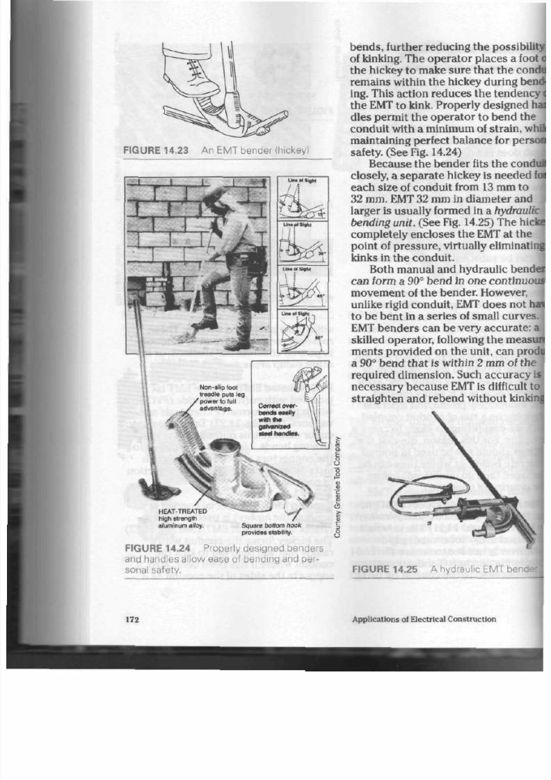
8/19/2019 Applications Electrical
http://slidepdf.com/reader/full/applications-electrical 177/447
FIGURE 14.23 An EMT bender (hickey)
I
.
4
rrm
bends , further reducing the possib
of kinking. The op era tor places a f
the hickey to make sure that th e co
rem ains within the hickey during b
ing. This action reduc es the tenden
the
EMT
to kink. Properly designe
dies permit the operator to bend t
con duit w ith a minimum of strain,
maintaining perfect balan ce for pe
safety. (See Fig. 14.24)
Because the ben der fits the co
closely, a sep ar ate hickey is nee de
each size of conduit from 13 mm t
32 mm .
EMT 32
mm in diam eter an
larger is usually formed in a hydr
bending unit. (See Fig. 14.25) The h
completely encloses the EMT at th
point of press ure , virtually elimina
kinks in the con duit.
Both manual and hy draulic
be
can form a 90° bend in one contin
movement of the bender. However
unlike rigid conduit, EMT does not
to b e ben t in a serie s of small curv
EMT ben der s can b e very accu rate
skilled operator, following the
me
ments provided on the unit, can p
a
90°
ben d th at is within 2 mm of
required d imension. Such accurac
necessary because
EMT
is difficul
straighten and rebend without kin
HEAT-TREATED
high strength
aluminum a lloy.
/
Square bottom hook
provides stability.
E
o
u
<3
S T
FIGURE 14.24 P roperly designed benders
and handles allow ease of bending and per
sonal safety.
FIGURE 14.25 A hydraulic E MT ben
172
Applications of Electrical Construction

8/19/2019 Applications Electrical
http://slidepdf.com/reader/full/applications-electrical 178/447
i though EMT does not require as
i physical strength to bend as does
I conduit, considerable practice is
before truly professional results
I be obtained. Many people who
I conduit take great pride in their
Figure 14.26 illustrates a high-
ity installation in a com mercial/
strial area.
T hr eaded f or R ig id C ondu i t S e t -s c rew t y pe f o r E M T
«*9
typeC
typeLR
type LB
typeLL
t y pe LL
type LR
typeE
• m
/
typeT
typeT
o
typeX
t:
8
m£. 14.26 A cond uit installation requir-
|a high degree of skill and craftsmanship
FIGURE 14.27 C onduit fittings (condulets)
Conduit Wiring
173
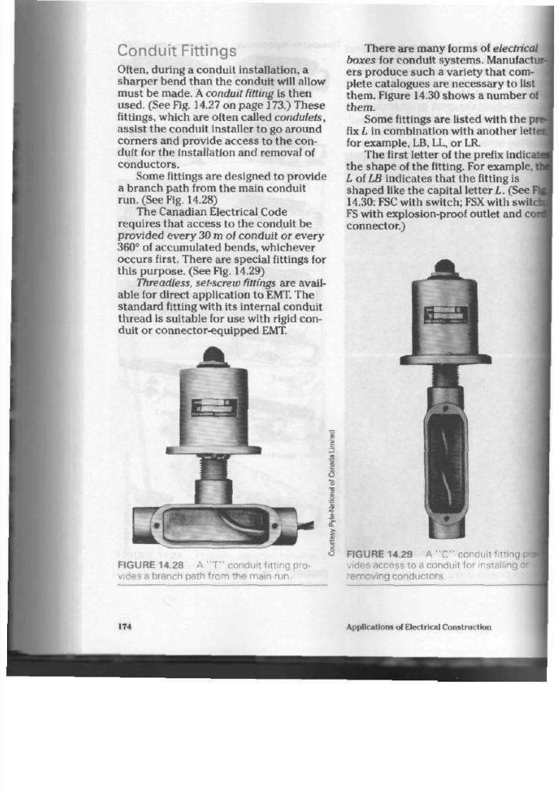
8/19/2019 Applications Electrical
http://slidepdf.com/reader/full/applications-electrical 179/447
Conduit Fitt ings
Often, during a cond uit installation, a
sha rpe r ben d tha n the co nduit will allow
must be made. A conduit fitting is th en
use d. (See Fig. 14.27 on pag e 173.) These
fittings, which are often called
condulets,
assist the c ondu it installer to go aroun d
corn ers and provide access to the con
duit for th e installation and remo val of
conductors.
Some fittings are designed to provide
a branch p ath from th e main condu it
run. (See Fig. 14.28)
The Canadian Electrical Code
requires that acc ess to the conduit be
provided every
30 m
of conduit o r ev ery
360° of accumu lated ben ds, wh ichever
occurs first. There are special fittings for
this purpose. (See Fig. 14.29)
Threadless, set-screw fittings a re avail
able for direct a pplication to EMT. The
standard fitting with its internal conduit
thre ad is suitable for use with rigid con
duit or connector-equipped EMT.
3
CD
CO
c
1
FIGURE 14.28 A
" T "
conduit fitting pro
vides a branch path from the main run.
There are many forms of
electri
boxes for conduit systems. Manufac
ers produce such a variety that com
plete catalogues a re nec essary to lis
them . Figure 14.30 sho ws a num ber o
them.
Some fittings are listed w ith th e p
fix
L
in com bination w ith ano ther
le
for example, LB,
LL,
or LR.
Th e first lette r of th e prefix indic
th e s ha pe of th e fitting. For exam ple
L of LB indica tes th at t he fitting is
sha ped like the capital letter
L.
(See
14.30:
FSC with switch; FSX with sw
FS with explosion-proof outlet and c
connector.)
<3 FIGURE 14.29 A
" C "
conduit fitting
vides access to a conduit for installing
removing conductors.
i
174 Applications of Electrical Construction

8/19/2019 Applications Electrical
http://slidepdf.com/reader/full/applications-electrical 180/447
toswn-proof motor starting units
FS fitting w ith explosion-
proof outlet and cord
connector
FSX fitting with switch
(4 conduit openings)
JBfcL
&
j
r fitting w ith switch
onduit
openings)
FS fitting (single
conduit opening)
10
c m
diameter
round box
HIRE 14.30 Typical electrical boxes for
fittings
Conduit Wiring
FS fitting
with motor
starting
switch and
pilot light
(2
gang)
175
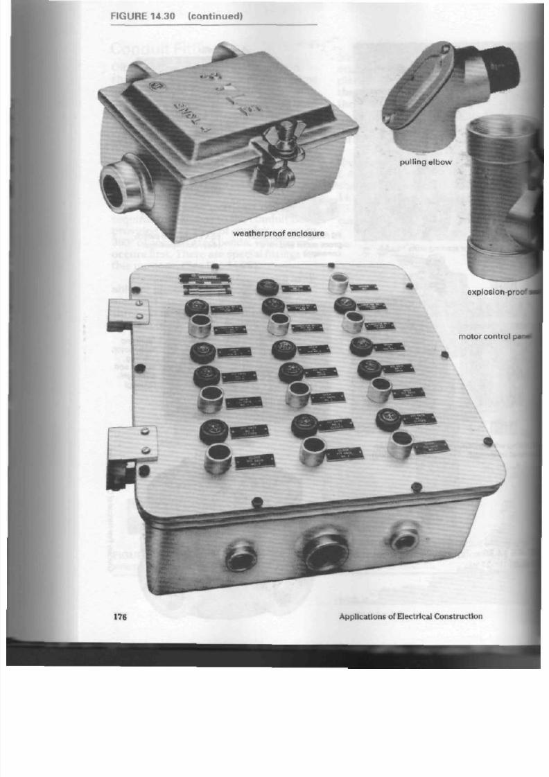
8/19/2019 Applications Electrical
http://slidepdf.com/reader/full/applications-electrical 181/447
F I G U R E 1 4 .3 0 ( c o n t i n u e d )
explosion-pro
176
A pplications of E lectrical C onstruction

8/19/2019 Applications Electrical
http://slidepdf.com/reader/full/applications-electrical 182/447
The secon d lette r of the prefix indi-
the location of th e conductor
opening in relation
to
the shorter
it opening; tha t is, th e d irection
short arm of the fitting is poin ting
the fitting is held with the conduc-
iccess opening facing th e viewer and
onger arm pointing up wa rds. For
le , when an
LR
fitting is he ld w ith
ronductor acce ss opening facing t he
and the longer arm is pointing
ards,
the short arm
of
the fitting will
pointing
to the right. An
LL
fitting
1 the sam e way will have its sh or t
I pointing to the left. An LB fitting will
e its short arm pointing backw ards.
Condulets can be cappe d with cov-
aade
from aluminum, steel, porce-
or
a
fibre com pos ition. When exc es-
moisture
is present, a
cork
or
rubber
must be used between cover and
(See Fig. 14.31)
FIGURE 14.32 Conduit connected to outlet
box
• MB*
N
raised blank cover
blank composit ion cover
V
a
5
u
I
gasket c
c
c
E 14.31 Condulet covers
rminating Conduit
en rigid cond uit is brou ght into
res through knockout holes,
locknuts
•d bushings are used to secure it to the
ax. (See Fig. 14.32) Th ese fasteners
st be installed tightly enough to pro-
I both mechanical security
(streng th) for the installation and
ground circuit continuity.
While it is always wise to u se a tool
for its intended purp ose, common prac
tice among electricians is to tighten the
locknut and bushing by placing the
blade of a screwdriver against the unit,
and then striking the ha ndle
of
the
scre wd river w ith th e flat side of a pair
of
pliers. (See Step 4, Fig. 11.4) A hammer
and cold chisel are often nee ded with
very large conduits.
Locknuts are usually made
of
steel
and have sharp teeth on one side to bite
in
to
the box and establish the ground
circuit.
Bushings, which provide
a
smooth
opening through which the conductors
can enter the box, are m ade of die-cast
aluminum, steel,
or
nylon. Steel bu sh
ings with a nylon inse rt are also availa
ble.
(See Fig. 14.33)
Conduit Wiring
177
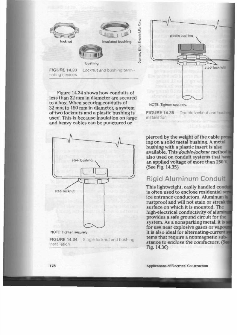
8/19/2019 Applications Electrical
http://slidepdf.com/reader/full/applications-electrical 183/447
locknut
- i
insulated bushing
F I G U R E 1 4 . 3 3
nat ing devices
bushing
L o c k n u t a n d b u s h in g t e r m i -
r
3
8
Figure 14.34 shows how conduits of
less than 32 mm in diameter are secured
to a
box.
When securing conduits of
32
mm
to
150 mm
in diameter, a system
of two locknuts and a plastic bushing is
used. This is because insulation on large
and heavy cables can be punctured or
NOTE: Tighten securely.
F IGU RE 14.35 Double
insta l la t ion
steel bushing
\
steel locknut
NOTE: Tighten securely.
F IG UR E 14 .34 S i ng l e l ocknut and bush i ng
instal lation
pierced by the weight of the cable pr
ing on a solid metal bushing. A meta
bushing with a plastic insert is also
available. This double-locknut meth
also used on conduit systems that I
an applied voltage of m ore than 250
(See Fig. 14.35)
Rigid A luminum Conduit
This lightweight, easily handled cond
is often used to enclose residential:
ice entrance conductors . Aluminum
rustproof and will not stain or streak
surface on which it is mounted. The
high-electrical conductivity of aim
provides a safe ground circuit for the
system.
As
a nonsparking m etal, it is
for use near explosive gases o r vap
It is also ideal for alternating-current
terns that require a nonmagnetic sub
stance to enclose the
conductors.
(S
Fig. 14.36)
178
Applications of Electrical C onstruction

8/19/2019 Applications Electrical
http://slidepdf.com/reader/full/applications-electrical 184/447
Rigid aluminum conduit
FIGURE 14.37 Rigid PVC conduit
•ending Rigid Aluminum Conduit.
•ding aluminum conduit does not
lire much physical effort. It does
rever
require th e u se of a hickey o r
le other forming device that will not
t the bend. Standard rigid conduit
beys can be u sed if extrem e c are is
tn
not to flatten the bend with too
a radius. EMT be nd ers one size
er than the conduit are often used
:essfully. Hydraulic benders also
•ally produce satisfactory bends.
ding Rigid Aluminum Conduit.
t used for threading aluminum con-
should be sharp and well-lubricated
le cutting the thre ad . Chips of m etal
uld be cleared from the die occasion-
Otherwise, they will lodge between
die and the conduit and tea r the
rly cut thre ads. When reaming this
duit, take ca re no t to flare and
d the end because bugling makes
lifficult to attach conduit fittings.
ailing Rigid A lum inum
Conduit,
poid cross-threading aluminum conduit
ihen
attaching coup lings, locknu ts,
tashings, con dule ts, or similar devices.
»e soft aluminum will quickly lose its
be ad s if an attem pt is made to remov e
wross-threaded fitting. Putting lubricat-
l oil on the threa ds before assem bly
I
help eliminate this p roblem.
Aluminum cond uit should be sup
ported by
straps
placed at regular inter-
is.
as is rigid steel c ond uit. The m ate-
I*s
light weight is appreciated,
ticularly during conduit installations
nm a ladder or some oth er precarious
sition.
If aluminum co ndu it is to b e e mbe d
ded in conc rete below ground w here it
may be wetted every so often, a
bitumi
nous base paint
or
pitch
should be
applied to the conduit . This su bstanc e
will protect the conduit from any mois
ture in the concrete that may attack the
metal and corro de it .
Rigid PVC C onduit
Rigid PVC (Polyvinylchloride) conduit
protec ts cond uctors in the worst corro
sive locations. Moisture or cond ensation
has no effect on this durable product.
Since PVC will not co nd uc t electricity
and is non ma gne tic, it is not affected by
shea th cu rren ts. It has no voltage limita
tions. It resists aging, exposure to ozone,
sunlight, and undergrou nd environ
m en ts. It is imm une to electrolytic
action. Heavy blows d o not cau se per
manent damage to it. (See Fig. 14.37)
W eight Ad va nta ge of Rigid PVC
Co nduit. This con duit is
approximately
five times
lighter than
steel conduit and twice as light as
aluminum condu it of the sa me size. As a
result, the installer finds it mu ch easier
to handle, especially when working from
ladders or scaffolds.
Applications of Rigid P VC Conduit.
This conduit is used in areas w here
corro sion is a prob lem, for exam ple, in
paper mills, meat-packing plants,
chemical and electroplating p lants,
barns and animal shelters, hospitals,
and food prep aration pla nts. It is also
Conduit Wiring
179

8/19/2019 Applications Electrical
http://slidepdf.com/reader/full/applications-electrical 185/447
being used more and more for residen
tial service entr anc e conduit, be cause it
is easily handled, nonrusting, and nons-
taining.
Joining and Terminating Rigid PVC
Conduit. A metal-cutting hacksaw or
carpenter's wood saw
can be used to cut
the conduit to length.
A pocketknife
will
quickly rem ove any bu rr on t he inside of
the cu t end. Leng ths of PVC and fittings
are assem bled by using a form of solvent
welding.
No thr ead s ar e required. Dirt
and grease from handling are removed
with a P VC cleaner. Solvent cement is
brush ed on to the prepared end of the
con duit and th e inside of the fitting to be
joined. The conduit is then pushed into
th e fitting, given a qu art er tu rn, and set
aside. After a few minutes the
con nec tion will w ithsta nd t he strain of
use. (See Fig. 14.38)
Bending Rigid PVC Conduit.
This
conduit is a thermop lastic m aterial that
will soften at temperatures between
115°C and 130°C. If proper care is taken,
the conduit will not flatten and/or kink
while being ben t. All be nd s should have
a rad ius of at least ten times t he
diameter of the conduit. Commercially
produ ced bend s are available from the
conduit's manufacturer.
There is an approv ed PVC heater that
directs a heated-air stream at the con
duit. This air stream is cap able of raising
the co nduit 's temp erature to the desired
level. Open flame will damage the con
duit and should not be used. Cold water
or natura l cooling will maintain th e
shap e of the bend. The conduit shou ld
be overbent slightly to allow for spring-
back as th e co ndu it is cooling. (See Figs.
14.39 and 14.40) Figures 14.41 and 14.42
illustrate several other forms of heating
equ ipm ent for bending rigid PVC con
duit. The heating blanket is used on
sizes of conduit and is
thermostatic
controlled for uniform bending . The
mo tor-driven elec tric PVC he ate r is
capable of automatically rotating th
conduit for even heating. Controls
include a heating chart and timer to
bring the PVC up to be nding tem per
ture.
Rigid P VC Conduit Expansion.
Whenever the temperature variation
excee ds a range of
15°C,
PVC condu
will expand and contract enough to
warra nt the u se of expansion joints.
expansion joint is simply one PVC tu
telescoping within another. A 30 m
length of conduit will expand
approx imately 9 cm . Expansion join
are available from th e man ufacturer
PVC con duit.
Rigid PVC Conductor Installation.
phys ical effort is need ed to pull
con duc tors into this condu it than in
other types. The conduit 's smooth,
friction-free inter ior is th e major rea
Rigid P VC Conduit Supports.
Supports for this conduit do not nee
be as sturdy as tho se for other form
condu it. They should be space d at
regular intervals and take into
accou
the possibility of snow, ice, and win
loads.
For example, ade qua te suppo
would be one s up po rt every 80 cm f
conduit
13
mm, 20 mm, and
25
mm
diameter.
Metallic Flexible Conduit
Flexible conduit (flex) combines
mechanical protection with maximi
flexibility for nonhazardous locatior
This versatile rac ewa y is made of an
interlocking steel or aluminum strip
180
Applications of Electrical Con struction
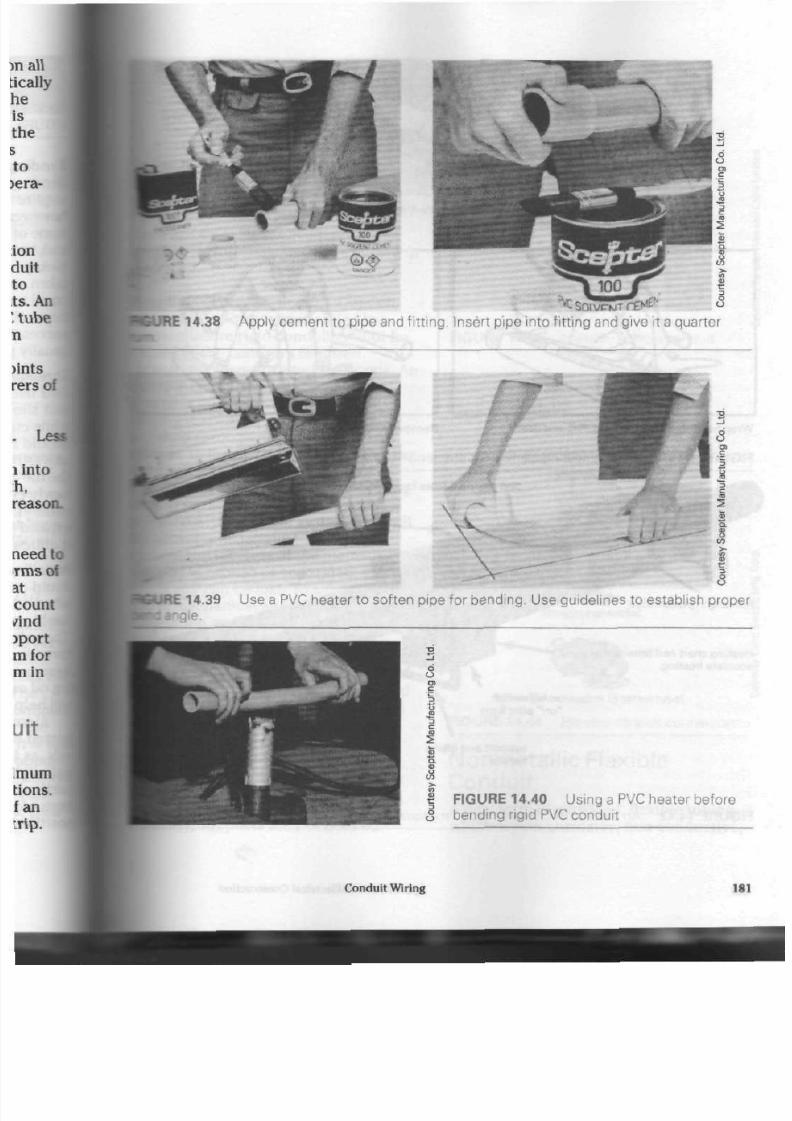
8/19/2019 Applications Electrical
http://slidepdf.com/reader/full/applications-electrical 186/447
100
JRE 14.38
A pply cement to pipe and f itt ing. Insert pipe into fitting and give it a quarter
E 14.39 Use a PVC heater to soften pipe for bending. Use guidelines to establish proper
wle.
o
U
£
FIGURE 14.40
Using a PVC heater before
bending rigid PVC cond uit
Conduit Wiring
181

8/19/2019 Applications Electrical
http://slidepdf.com/reader/full/applications-electrical 187/447
full-length piano hinge
Heating chart and timer allow easy
accurate heating .
on/off switch
" o n "
pilot light
support and lifting
handle
F IG U RE 14 .42 A n e l ec tr ic P VC heater w i th a m otor i zed condu i t - ro ta t ion fea tu re
Applications of Electrical Construction

8/19/2019 Applications Electrical
http://slidepdf.com/reader/full/applications-electrical 188/447
TABLE 14. 1 Me tallic Flexible C ondu it
Internal Diameter
8 mm
13 mm
32 mm
64 mm
9.5 mm
20 mm
38 mm
75 mm
11
mm
25 mm
51 mm
100 mm
Standard Length of Coil
7.5 m 30 m
75 m
«e Fig. 14.43) Flex is availab le in th e
tgths and internal diameters show n in
He 14.1.
illic
Flex Ap plications. Conduit
Krtection is sometimes needed in a
ration where rigid conduit cannot be
fcrmed to the con tours required
ecause
of close-working c on dition s. An
sample
is a wiring system tha t mu st
lass over and around steel girders,
Bsting mach inery and equipment, o r
- shed through ma sonry walls and
attngs. Using flex g reatly simplifies th e
Btallation work. Another exam ple is
tors and/or machines with vibrating
.ing
pa rts . The se parts must b e
•ovided with a supply syste m tha t will
Bt allow metal fatigue to set in and
tacture th e raceway . If th e m etallic
•ceway is broken or separa ted, ground
•tinuity can b e lost . To accom m odate
•und
mechanical and electrical
•tallation
methods, approved flex
••nectors must be used. (See
14.44)
Supports
for Metallic Flex. Appro ved
ex
sup ports are similar to thos e used
•th armoured cable. They must be
•tailed within 30 cm of each box or
binet and at regular intervals of not
•ore than 1.4 m throu gho ut th e run.
Pee
Fig.
14.45) Where flex is fished or
Bed in lengths of up to
1 m
requiring
Inability, su pp orts are not need ed.
a
O
FIGURE 14.43 Me tallic flexible cond uit
st raight conne ctors (squeeze type)
90° angle connector (squeeze type)
o
straight connector
90° angle c onne ctor (3 screw type)
FIGURE 14.44 Flexible conduit connectors
Nonmetall ic Flexible
Conduit
A
new form of extruded, flexible tubing,
which is non-corrosive, n on-condu ctive,
Cond uit Wiring 183

8/19/2019 Applications Electrical
http://slidepdf.com/reader/full/applications-electrical 189/447
FIGURE 14.45
(2-hole)
f
Flexible condu it strap | g
and m oisture resistant, is now av ailable.
This lightweight tubing can be ob tained
in coils up to app roxim ately 100 m in
length.
Special connectors and couplings
exist for use w ith this p rod uc t only. With
their fast-acting,
snap-on
feature, the y
allow th e installer to inse rt th e flex into
the connector/coupling without the use
of any tool or piece of equipm ent. It
should be noted, however, tha t some
times the solvent-welding technique (as
used with PVC con duit) may be required
by local wiring co de s. Wh ichever
m eth od is used , the flex is not easily
removed from the connector/coupling
onc e installed. Figure 14.46 illustrate s
th e snap-on connector. Figure 14.47 illus
trates a snap-on coupling.
Nonm etal l ic Flex Appl icat ions.
Nonmetallic flexible conduit is often
used in metal-stud partitions (see Fig.
14.48) and poured con crete work. (See
Fig. 14.49) Care mu st b e taken not to use
this product in hazardous locations (as
des crib ed in th e Canadian Electrical
Code),
however. It shou ld a lso not be
buried in the earth , exposed to
mechanical injury, or enclosed in
thermal insulation materials.
Sup ports for Non metallic Flex. Fishing
of wires into the flex is ea sed by t he
corrugated design on the interior: the
corrugation results in less friction when
the co ndu ctors are pulled into the
tubing. (See Fig. 14.50) Flex should have
a sup po rt within
1
m of a junction box,
coupling, or fitting, plus supports no
184
more than 1 m ap art o n a ru n. It is a\
ble
in 13 mm , 20 mm , and 25 mm inte
diameters.
FIGURE 14.48 Typical use of PVC f
conduit in metal stud partitions
Applications of Electrical Construction

8/19/2019 Applications Electrical
http://slidepdf.com/reader/full/applications-electrical 190/447
o
WE 14.49 This PVC flexible condu
prepared for use in a concre te slab.
tis
o
u
<
2
> t5
J 8 5
c
JRE 14.50 PVC flexible conduit
|uid-Tight Flexible
mduit
kcs PVC-jacketed flex
is excellent for
e in
damp locations, corrosive areas,
[around machines where coolants, cut-
tog. and/or lubricating liquids are likely
splash on to the flex. (See Fig. 14.51)
bisture-proofconnectors are used to ter-
taate
it. (See
Fig.
14.52 on page 186.)
tese
con nec tors make use of a
nylon
wipression
ring to grip the outer jacket;
fariar
flex con ne cto rs hav e a metallic
•raping
device.
•
nouio-riGm CONOU II IIOU'S«AI I*D{
U t t f f
IRE 14.51 L iquid-tight, flexible
v conduit w ith a PVC jacket
10 .Q
Take care no t to p unc ture th e PVC
jacket either during installation or later
when it is in use.
The Canadian Electrical Code
requires that this conduit not be u sed
where temperatures are higher than
60°C. These temperatures could dam age
the
PVC
jacket. Also, take ca re not to use
the condu it in tempe ratures that are low
enough to cau se injury to the jacket
when it flexes.
Section 12 of the Canadian Electrical
Code lists guidelines for the ty pe an d
size of con du cto rs allowed in liquid-tight
flexible conduit.
Condui t Grounding and
Terminat ion
Acc ording to th e Canadian Electrical
Code, neither metallic nor nonmetallic
conduit can be relied upon for ground
continuity.
A separate conductor (green
insulation) with the sole purpo se of
grounding the equipment must be
installed toge ther with the other cur
rent-carrying cond ucto rs in the system.
Cutting th e Flex.
Cut flex to leng th
with a hacksaw in the same m anner as
for arm oure d cab le. (See Fig. 11.4)
Terminating the Flex.
Flex con ne ctors
are used to secu re the flex to bo xes,
cabin ets, or condu lets, and to couple the
flex with oth er forms of con du it. (See
Fig. 14.44 on pag e 183.) An insulating
sleeve,
similar to the anti-short bushing
used with armo ured cab le, must b e
inserted between the cond uctors and
the armour to prevent chafing of the
con du ctors . Some mo dern flex
conne ctors have a plastic insert built
into th e thread ed end of th e unit.
Flex connectors should be fastened
Conduit Wiring 185

8/19/2019 Applications Electrical
http://slidepdf.com/reader/full/applications-electrical 191/447
•
7.
straight connector
% * <
45°
connector
90°
connector
FIGURE 14.52
coupling
I
combination coupling
L iquid-tight con nectors and
securely to the box or cabinet w ith a
condu it locknut to provide m echanical
secu rity and assist in ground continuity.
Knockout Cutters
It is often nec essa ry to increa se the size
of an available knock out in a box or c abi
net. Using a ream er or file ten d s to be
clumsy, time-consuming, and damaging
to the wo rker 's hand s. Instead a knock
out cutter could be used.
These c utters are m ade in all s tand
ard c on duit sizes . Using, for exam ple, a
20 mm knocko ut c utter will produ ce an
ope ning that will acc ept a
20
mm con
duit or conn ector. The actual diam eter
of the h ole will be ap prox imately 27 mm.
The
hand-operated
cutter unit has a
hardene d-steel cutter, which is drawn
through the m etal box by a wrench-
tightened bolt. (See Fig. 14.53)
Once the knockout cutter has
removed a ring-shaped section of m etal
from th e box, th e installer may ha ve
som e difficulty in remo ving th e m etal
piece from th e cutter. He or s he can eas
ily w aste valu able time before making
the n ext hole in the box o r pan el. How
ever, a recently designe d typ e of c utte r
186
FIGURE 14.53 Hand-operated knock
punches
Applications of Electrical Construction

8/19/2019 Applications Electrical
http://slidepdf.com/reader/full/applications-electrical 192/447
up to 10 gaug e mi ld
; s lug for easy rem oval
-
T
The punch
creasesthe
slug as it is
drawn into
th e die.
The slug is split
in hall as the
punching opera
tion is com
pleted.
/ J{
*-/\
t y ^ \ / i
Jto< /
^n2\v}
^ J / 7
C^
Sp lit slugs fall
free from the
die an d
stud.
. 14.54 N ew ly designed knockout punches require less time to
slugs than traditional c utte rs.
each metal slug into two s eparate
5.
The installer can there by remove
etal pieces quickly. This cu tter is
)le
in traditional kno ckout cutte r
(See Fig. 14.54)
Hydraulic-powered
units use the
I
type of hardened-steel cutter, but
:
much less physical effort on the
of th e op era tor. (See Fig. 14.55)
Smaller, compact, lightweight
hydrau-
ch drivers
are available to install-
These units can be stored and their
i
organized in custom-fitted ca ses .
i Figs. 14.56 and 14.57)
•-:,
FIGURE 14.56 C ompact hydraulic punch
systems ease hole-making operations in
metal boxes and cabinets.
•5URE
14.55
utpunch
nyOrau
r^C^TZM
liC-pOWGrGQ
o
Conduit W iring
FIGURE 14.57 Hydraulic punch driver set
187

8/19/2019 Applications Electrical
http://slidepdf.com/reader/full/applications-electrical 193/447
Install ing the C onductors
The Canadian Electrical Code requires
that conductors be drawn into the con
duit system after the system h as been
completely assembled. Otherwise, con
ductors could be damaged while bend
ing, forming, or fastening th e cond uit to
boxes.
A
flattened,
tempered-steel
wire,
wh ich is prod uce d in 7.5 m, 15 m , 30 m,
and 60 m lengths, is pushed into the con
duit between boxes and fittings. This
steel wire, called a
fish tape,
is available
in 3 mm, 5 mm, and 6 mm widths to suit
light and heavy cond ucto r installations.
For ease of handling and storage , th e
tap e is wound onto a metal or plastic/
nylon reel. Figure
14.58
illustrates th e
older style metal reel. Figure 14.59 dis
plays the mo st comm on sizes of plastic/
nylon reels available to th e installer.
The tape is usually inserted into the
con duit b y mean s of a serie s of sho rt fre
quent p ush es. It is impo rtant to keep t he
5
FIGURE 14.58 Metal fish tape reel
188
tape in motion, because constant j
ing and vibration allow the tape to
eased arou nd b end s and offsets in
;
conduit. Figure
14.60
illustrate s a
I
us e of the fish tape /reel for the insc
of cond uct ors into conduit wiring
systems.
FIGURE 14.59 N umerous sizes of
nylon/plastic reels are available for use
\
fish tapes.
Applications of Electrical Construction
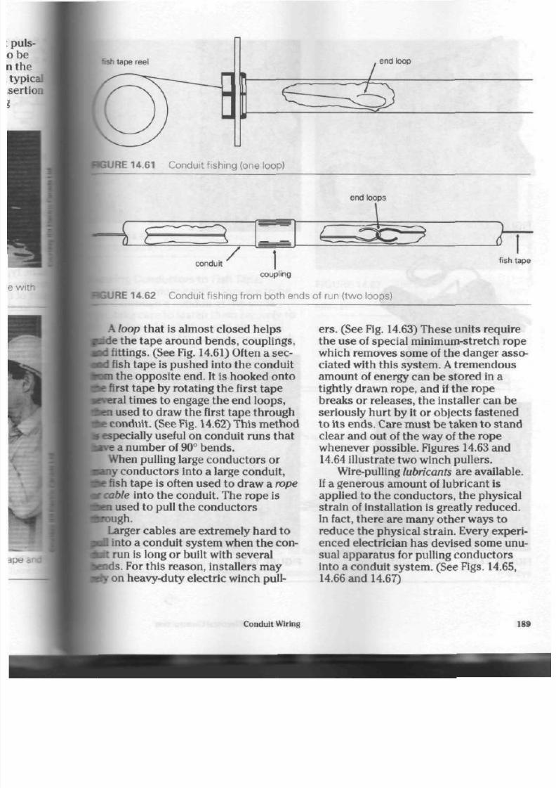
8/19/2019 Applications Electrical
http://slidepdf.com/reader/full/applications-electrical 194/447
fish tape ree
end loop
URE
14.61 Conduit fishing (one loop)
end loops
conduit
fish tap
coupling
RE 14.6 2 C ondui t f i s h ing f rom bot h ends
of run (two
loops)
i
A loop that
is
almost closed helps
•de the tape around bend s, couplings,
fed fittings. (See Fig. 14.61) Often a sec-
Ad fish tape
is
push ed into the conduit
torn the oppos ite end. It is hooked on to
fee
first tap e by rotating th e first tap e
rveral
t imes
to
engage the en d loo ps,
feen
used
to
draw the first tape throug h
fee con duit. (See Fig. 14.62) This m eth od
s especially useful on conduit ru ns that
tave
a number
of
90° ben ds.
When pulling large conductors
or
•any condu ctors into
a
large conduit,
fee fish ape is
often
used to draw a
rope
t
cable into the con duit. The rope
is
fcen used
to
pull the con ducto rs
• rough .
Larger cables are extremely hard to
poQ into
a
conduit system when the con-
pit run
is
long
or
built with s eve ral
ends . For this reaso n, installers may
try
on heavy-duty electric w inch pull
ers.
(See Fig. 14.63) These units require
the use
of
special minimum-stretch rope
which rem oves som e of the dang er asso
ciated with this system . A t remendous
amount
of
energy can be store d in
a
tightly drawn rop e, and if th e rop e
breaks
or
releases, the installer can
be
seriously hurt by
it or
objects fastened
to i ts end s. Care mu st be taken to stand
clear and out of the way of the rope
wh ene ver pos sible. Figures 14.63 and
14.64 illustrate two w inch pullers.
Wire-pulling lubricants are available.
If a generous am ount of lubricant is
applied
to
the conductors ,
the
physical
strain
of
installation
is
greatly redu ced.
In fact, th ere a re many othe r ways
to
reduce the ph ysical strain. Every experi
enced electrician has devised some unu
sual apparatus
for
pulling co nd ucto rs
into
a
cond uit sys tem . (See Figs. 14.65,
14.66 and 14.67)
Conduit Wiring

8/19/2019 Applications Electrical
http://slidepdf.com/reader/full/applications-electrical 195/447
FIGURE 14.63 Heavy-duty
electric winch pulling system
FIGURE 14.64
system
E lectric winch pulling FIGURE 14.65 Wire-pulling
luoncant is
available in
a
variety of easy-to-use conta
190 Applications of Electrical Construction

8/19/2019 Applications Electrical
http://slidepdf.com/reader/full/applications-electrical 196/447
14.66 Wire-pu lling lubricant is
plied to condu ctors.
ing Conductors to Fish Tape,
n two or more conductors are to be
ed
through a conduit at the same
take care to fasten them securely to
Ksh
tape. Much time and effort will
wasted if any of the conduc tors break
y
from the tape. Figure
14.68
shows
i
methods for securing the
•luctors
to a tape.
FIGURE 14.67 T he pulling of conductors
is eased by the application of wire-pulling
lubricant.
end loop
Wrap one conductor
around other.
conductors
Remove insulation.
N O T E :
It is good practice to cover a connection wi th tape.
Tape over end loop.
wire rope strands
'W ^K*®*
tape \^
> i i i
^ *
c a b l e s o c k
N O T E :
The greater the pull on the fish tape, the tighter the sock grips.
IE 14.68 M e t h o d s f o r s e c u r i n g c o n d u c t o r s t o f i s h t a p e
Conduit Wiring
191
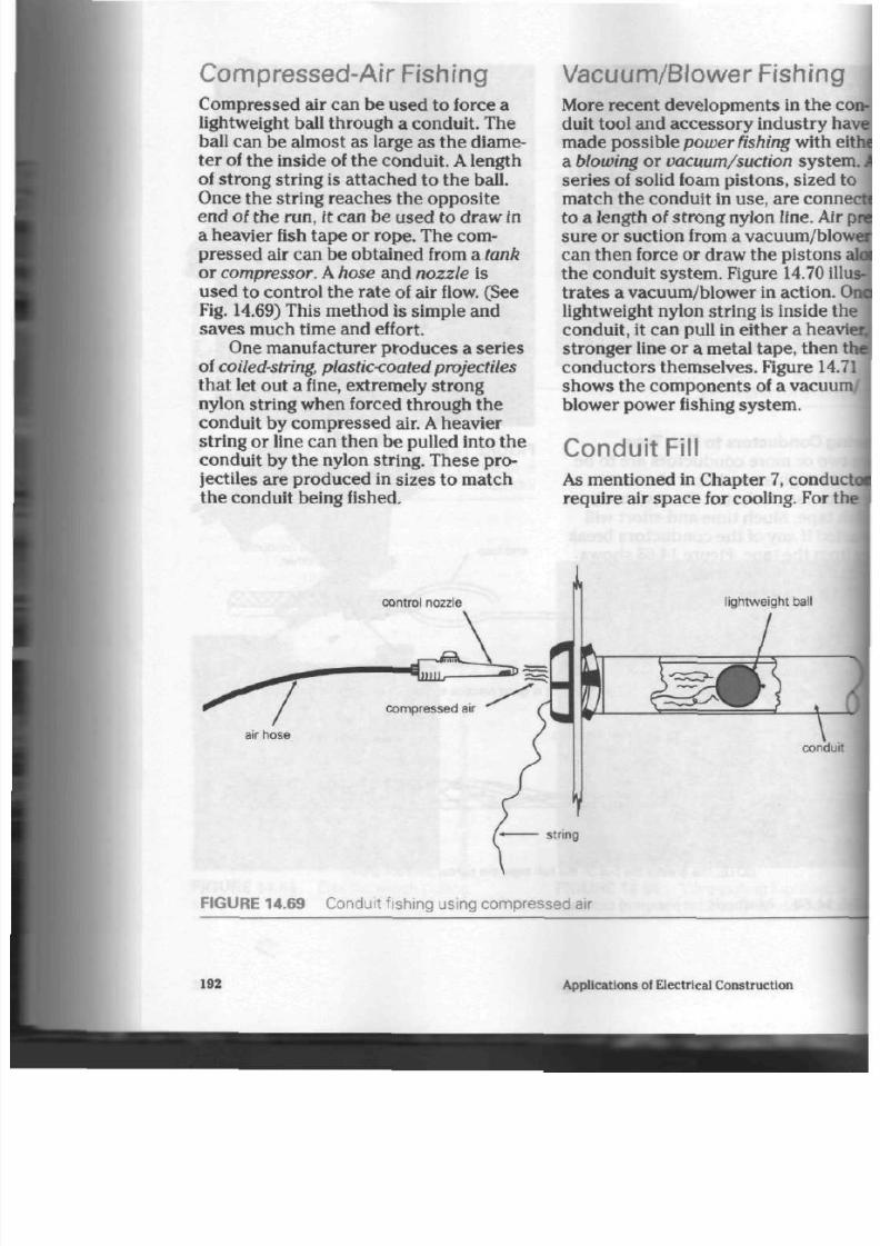
8/19/2019 Applications Electrical
http://slidepdf.com/reader/full/applications-electrical 197/447
Compressed-Air Fishing
Compressed air can be used to force a
lightweight ball throug h
a
condu it. The
ball can be alm ost as large as the diame
ter
of
the inside
of
the conduit . A length
of strong string is attached to the ball.
Once the str ing reaches the opposite
end of th e run, it can b e used to draw in
a heavier fish tap e or rope. The com
pressed air can be obtained from
a
tank
or compressor. A hose and nozzle is
used
to
control the ra te
of
air flow. (See
Fig. 14.69) This m ethod is sim ple and
sav es much time and effort.
One manufacturer produces a series
of coiled-string, plastic<oated projectiles
that let out a fine, extremely strong
nylon string when forced through
the
conduit by compressed air.
A
heavier
string or line can th en be pulled into the
conduit by the nylon string. The se pro
jectiles are produced in sizes to match
the conduit being fished.
Vacuum/Blower Fishing
More recent developments in th e
duit tool and accessory industry h
made possible power fishing with
a blowing
or
vacuum/suction syste
series of solid foam pisto ns, sized
match th e conduit
in
use , are
con
t o a length of strong nylon line. Ai
sure
or
suction from a vacuum/blo
can then force or draw the pistons
th e condu it sy stem . Figure 14.70 i
tra tes a vacuum /blower in action.
lightweight ny lon string is inside t
conduit,
it
can pull
in
either a hea
stronge r line or a metal tape, then
conductors themselves. Figure 14
shows the components of a
vacuu
blower power fishing system.
Conduit Fill
As men tioned in Chapter 7, condu
requ ire air sp ace for cooling. For
control nozzle
ightweight ball
*C— ^^
compressed air
air hose
condu
FIGURE 14.69 Conduit fishing using compressed air
192
Applications of Electrical Construction

8/19/2019 Applications Electrical
http://slidepdf.com/reader/full/applications-electrical 198/447
te
reason, the number of conductors
ny
given size of con duit or tubin g
be limited. The Canadian Electrical
le
specifies the num ber allowed. This
liber dep en ds on the con duc tor size
I
type of insulation. (See Table 14.2)
To determine th e num ber of conduc-
allowed, Table 14.2 is used with
: 5.1.
(See Ch apte r 5) For exam ple, a
14
gauge stranded conduc tor ha s a
-75 insulation thickness of 0.8 mm or
mm when you con sider b oth s ides of
condu ctor. When 1.6 mm is ad ded to
conductor 's approximate diam eter
L4
mm, a fairly a cc ura te dia m eter of
I mm
is estab lishe d. (See Table 5.1) To
FIGURE 14.71 C omponents of a
vacuum/blower power fishing system
determine how many of these conduc
tors are allowed in 13 mm tubing, look
for the dia m eter en try equ al to (and , if
necessary, larger than) 5.0 mm on Table
14.2. In this ca se, the no minal overall
diam eter is 5.1 mm , which allows th ree
con duc tors in the tube .
Since editions of the Code book con
tinue to be in th e imperial syste m of
m eas urem ent, t he following cond uit fill
me thod is included.
For simplified conduit fill calcula
tions, refer to Table
14.3
on p age 195.
This table lists the comm on tra de sizes
and ca pac ities of cond uit to be installed
with
RW-75
or R-90 insulated con du c
tor s. Its information is m ost useful w hen
the conductors to be installed in the
conduit are all of one type and gauge
size.
A
m ore detailed m ethod of arriving
at conduit fill is recommended when
con du ctors of various size and gauge
num ber are to be installed. (See Tables
14.4 and 14.5 on pages 196 and 197.)
Condu it Wiring
193

8/19/2019 Applications Electrical
http://slidepdf.com/reader/full/applications-electrical 199/447
TABLE 14.2 M ax im um N umb er of C ondu c t ors o f O ne S iz e in T rade S iz es
Nominal *
Overall
Diameter
of
Condr.**
mil l imet res
2.5
2.8
3.0
3.3
3.6
3.8
4.1
4.3
4.6
4.8
5.1
5.7
6.4
7.0
7,6
8.3
8.9
9.5
10.0
10.8
11.0
12.0
13.0
14.0
15.0
16.5
18
0
19.0
20.0
22.0
23.0
24.0
25.0
28.0
30.0
33.0
36.0
38.0
41.0
43.0
46.0
48.0
50.0
64.0
***
* For intermediate si
• * For the purpose of
13
15
12
10
9
7
6
6
5
4
4
3
3
—
—
—
—
—
—
—
—
—
—
—
—
zes, use
conduit 1
20
27
22
18
15
13
11
10
9
8
7
6
5
4
3
3
1
—
—
—
—
—
—
—
—
the next
II, 'cond
of Condui t or Tub ing
Maximum Number of Conductors in Conduit or Tubing
Size of Conduit or Tubing—Mill imetre
25
4 4
36
30
26
22
19
17
15
13
12
10
8
7
5
4
4
3
3
2
—
—
—
—
—
—
30
76
63
53
45
39
33
29
26
23
21
19
15
12
10
8
7
6
5
4
4
3
3
3
—
40
101
85
72
61
53
46
40
35
32
28
26
20
16
13
11
9
8
7
6
5
5
4
4
3
2
1
50
171
141
119
105
87
76
67
59
53
47
42
33
27
22
19
16
13
12
10
9
8
7
6
5
4
4
3
3
2
1
65
—
169
143
124
108
95
84
75
67
60
48
38
32
27
23
19
17
15
13
12
10
9
8
6
5
4
4
3
3
3
2
1
1
1
1
1
1
1
1
1
75
—
—
—
192
163
146
130
116
104
94
74
60
49
41
35
30
26
23
20
18
16
15
12
10
8
7
6
5
5
4
4
3
3
2
90
—
—
—
197
174
155
139
126
99
80
66
56
47
41
35
31
27
24
22
20
16
14
11
10
8
7
6
6
5
5
4
3
2
1
arger dimension (e.g., for conductor with diameter 5.3 m m, u
jctor' means either insulated conductor, single or multiconduc
100
—
—
—
—
—
—
199
178
162
127
103
85
71
61
52
46
40
35
31
28
25
21
18
15
13
11
10
8
7
7
6
5
4
3
3
2
1
1
1
1
1
1
115
—
—
—
—
—
—
—
—
—
—
161
130
108
91
77
66
57
51
45
40
36
32
27
22
19
16
14
12
11
10
9
8
6
5
4
4
3
3
3
1
1
1
1
>e fill for 5 7 mm)
tor cable.
130
—
—
—
—
—
—
—
—
—
—
—
162
134
113
96
83
72
63
56
50
45
40
33
28
24
20
18
15
14
12
11
10
8
7
6
5
4
3
3
3
2
1
1
194 Applications of Electrical Construction

8/19/2019 Applications Electrical
http://slidepdf.com/reader/full/applications-electrical 200/447
If, for example, a No. 8 gauge cond uc-
w
with R-90 insulation w as to be
stalled, you could refer to Table 14.4
id find tha t the co ndu ctor h as an area
f
0.076 0 in.
2
.
If 1
in. cond uit is to b e
stalled, you could refer to Table 14.5
tiich lists the c ross-sec tional are as of
te
conduits and their allowable percen-
ges of fill. From Table 14.6 you can find
lat three or m ore con du ctors in a given
conduit m ust not occu py m ore than 40%
of the available space in the conduit.
The
40%
column of Table 14.5 shows
that 1 in. conduit has a cross-sectional
area of 0.344 in.
2
. If yo u div ide 0.344 in.
2
by the conductor's area of
0.076
0, you
will arrive at an a nsw er of 4.52 cond uc
tors . Therefore, you can determ ine th at
four conductors could be installed in the
1 in. condu it, as s how n in Table 14.3.
6*
39
12:
10*
A
23
::
is
IE
•*
12
•:
;
5 i
L
L
T A BL E 14.3 Ma ximum N umber of Conductors of O ne Size in Trade Sizes
of Conduit or Tubing
HOTE:
For ampacity derating factors for more than three conductors in raceways, see Rule 4-004 in the
^^fnadian Electrical Code.
See of Conduit
or
lofting—Inches
Conductor
1 *"*
T
M C
Size
AWG.
MCM
14
12
10
8
6
4
3
2
1
0
00
000
0 000
250
300
350
400
500
600
700
750
800
900
1 000
1 250
1 500
1 750
2 000
Vt
3
3
2
1
1
0
0
0
0
0
0
0
0
0
0
0
0
0
0
0
0
0
0
0
0
0
0
0
%
6
5
4
2
1
1
1
1
1
0
0
0
0
0
0
0
0
0
0
0
0
0
0
0
0
0
0
0
1
10
9
7
4
2
1
1
1
1
1
1
1
0
0
0
0
0
0
0
0
0
0
0
0
0
0
0
0
I V .
18
15
13
8
5
3
3
3
1
0
0
0
0
0
0
0
0
0
0
0
0
V/z
25
21
17
10
6
5
4
4
3
2
1
1
1
1
1
1
1
1
0
0
0
0
0
0
0
0
0
0
2
41
35
29
17
11
8
7
6
5
4
3
3
2
1
0
0
0
0
2 V J
58
49
41
25
15
12
10
9
7
6
5
4
4
3
3
1
1
1
1
1
1
1
1
1
1
0
0
0
3
90
77
64
39
24
18
16
14
11
9
8
7
6
5
4
3
3
3
2
1
1
1
1
1
1
1
1
1
3'/2
121
103
86
52
32
24
21
19
14
12
11
9
8
6
5
5
4
4
3
3
3
2
2
4
155
132
110
67
41
31
28
24
18
16
14
12
10
8
7
6
6
5
4
4
3
3
3
2
1
1
1
1
4V2
195
166
138
84
51
39
35
31
23
20
18
15
13
10
9
8
7
6
5
4
4
4
4
3
3
2
1
1
5
200
200
174
105
64
50
44
38
29
25
22
19
16
13
11
10
9
8
6
6
5
5
6
A
3
3
2
2
6
200
200
200
152
93
72
63
56
42
37
32
28
24
19
17
15
14
11
9
8
8
8
7
6
5
4
4
3
Conduit Wiring 19

8/19/2019 Applications Electrical
http://slidepdf.com/reader/full/applications-electrical 201/447
TA B LE 14 .4 D ime ns ions o f Ins u la t ed C ondu c t ors f or C a lc u la t ing Con dui t and Tubing F il
Size
AWG
M C M
14
14
14
12
12
12
10
10
10
8
6
4
3
2
1
0
00
000
0 000
250
300
350
400
500
600
700
750
800
900
1 000
1 250
1 500
1 750
2 000
"These ar
NO T E: To c
Rubber (ThermosetJ- and Thermoplastic-Insulated Conductors
(0 V—600 V I
Types
RW-75 end R-90
Diameter
Inches
(2/6410.171
(3/64)
0.204*
—
(2/64)0.188
(3/64)
0.221
*
—
0.242
—
—
0.311
0.397
0.452
0 481
0.513
0.588
0.629
0.675
0.727
0.785
0.868
0.933
0 9 8 5
1.032
1.119
1.233
1.304
1.339
1.372
1.435
1.494
1.676
1.801
1.916
2.021
B the dimensions fo
alculate conduit and
Area
Square
Inches
0.0230
0.032 7*
—
0.027 8
0. 0384*
—
0.0460
—
—
0.0760
0.123 8
0.160 5
0.181 7
0.206
7
0.271 5
0.310 7
0.357
8
0.4151
0.484 0
0.591 7
0.683 7
0.762
0
0.8365
0.983 4
1.1940
1.335 5
1.408 2
1.478 4
1.6173
1.753 1
2.206 2
2.547 5
2.889 5
3
207 9
types RW-75
tubing fill using
Types T . T W . T W H .
THHNJ, RW -76 (XLPE) i
RW-90 (XLPEIS
R-90 Silicone.
R-90
(XLPEI
i
Diameter
Inches
0 .131
0.166
—
0.148
0.183
—
0.168
0.204
—
0.248
0.323
0.372
0.401
0.433
0.508
0.549
0.595
0.647
0.705
0.788
0.843
0 8 9 5
0.942
1 029
1.143
1 214
1.249
1 282
1.345
1 404
1.577
1.702
1.817
1.922
Area
Square
Inches
0.013 5
0.021 6
—
0.017 2
0.0263
—
0.022 4
0.032 7
—
0.047
5
0
081
9
0.1087
0.1263
0.1473
0.202 7
0.2367
0.278 1
0.328
8
0.390 4
0.487 7
0.558 1
0.629
1
0.6969
0.8316
1.026 1
1.1575
1.225 2
1.290 8
1.420
8
1 548 2
1.9532
2.274 8
2.593 0
2.9013
ind R-90.
metric measu rements, refer t
Types
TWU,
RWU-75 (XLPEI i
RWU-90 (XLPEI
f
Diameter
Inches
—
0 193
—
0.209
—
—
0.230
0.324
0 3 6 3
0.412
0.440
0.473
0.544
0.585
0.632
0.684
0.744
0.822
0.878
0 9 3 0
0.978
1 064
1.180
1.252
1.287
1.321
1.385
1.444
1 616
1.741
1.858
1
966
Area
Square
Inches
—
—
0.029 3
—
0.034 3
—
—
0 041 5
0.082
4
0 1 0 3 5
0.1333
0 152 1
0.1757
0.232 4
0.2688
0.313 7
0.367
5
0.434 7
0.530 7
0.605 5
0 6 7 9 3
0.751 2
0.889 1
1.093 6
1.231 1
1.300 9
1.370 6
1.5066
1.637 7
2.051
0
2.380 6
2.7113
3.035
7
o page 193 of the text for gui
Types RW U-75 EP
RWU-90 EP
Diameter
Inches
—
—
0 2 3 1
—
0.247
—
—
0.268
0.345
0 456
0.505
0.533
0.566
0.649
0.690
0.737
0.789
0.849
0.977
1.033
1.085
1.133
1.218
1.301
1.373
1.408
1.442
1.506
1.565
1.809
1.934
2.051
2.159
lance.
Are
Sque
Inch
—
0.04
—
—
—
0.05
0.0
016
0.2
0.22
0.25
0 3
0.3
0.4
0.48
0.56
0.7
0 83
0 92
1.00
1 16
1 3 2
1.48
1.55
1.63
1.78
192
2.57
2
93
3 3
3.66
196 App lications of Electrical Construction

8/19/2019 Applications Electrical
http://slidepdf.com/reader/full/applications-electrical 202/447
1
0
TABLE 14.5 C ros s -S ec t iona l A reas o f C ondui t and T ubing
Sam
1 metres
- *
*
:
2 -
3 :
1 :
£
s
Internal
Diameter
Inches
0.622
0.824
1.049
1.380
1.610
2.067
2.469
3.068
3.548
4.026
4.506
5.047
6.065
Per Cent C ross-Sectional Area of C onduit and Tubing—Square Inches
1 0 0 %
0.30
0.53
0.86
1.50
2.04
3.36
4.79
7.38
9.90
12.72
15.94
20.00
28.89
5 5 %
0.165
0.292
0.473
0.825
1.122
1.848
2.635
4.060
5.450
7.000
8.771
11.000
15.900
53%
0.159
0.281
0.456
0.795
1.081
1.780
2.540
3.910
5.250
6.745
8.452
10.600
15.320
4 0 %
0.120
0.212
0.344
0.600
0.816
1.344
1.916
2.952
3.960
5.088
6.378
8.000
11.556
38%
0.114
0.202
0.327
0.570
0.776
1.277
1.820
2.805
3.765
4.840
6.060
7.600
10.980
3 5 %
0.105
0.185
0.301
0.525
0.714
1.176
1.677
2.585
3.465
4.450
5.581
7.000
10.120
3 1 %
0.09
0.16
0.27
0.47
0.63
1.04
1.48
2.29
3.07
3.94
4.94
6.20
8.96
3 0 %
0.090
0.159
0.258
0.450
0.612
1.008
1.437
2.214
2.970
3.820
4.784
6.000
8.670
E Metric equ ivalents are not provided here , because they have no application in the electrical industry.
T
ABLE 14 .6 M a x i m u m A l l o w a b l e P e r C e n t C o n d u i t a n d T u b i n g F ill
iaro-clo's or multi-conductor cables
• c
sad-sheathed)
la«o-sreathed conductors or multi-conductor cables
Maxi mum Conduit and Tubing Rll
Par Cant
Numbar
o f
Conductor*
or Multi -conductor
Cablas
1
53
55
2
31
30
3
40
40
4
4 0
38
Ovar
4
40
35
Conduit Wiring
1«7

8/19/2019 Applications Electrical
http://slidepdf.com/reader/full/applications-electrical 203/447
F o r R e v
i e w
1. List three main advantages that a
conduit wiring system has over
othe r wiring system s.
2.
List three a reas w here a conduit
wiring system is used to protect
the power supply.
3. In what length is conduit usually
produced? in what diameters?
4. How is conduit mea sured to deter
mine its trad e size?
5. List five main types of conduit.
6. Why is the inside of rigid con duit
coated with insulating paint or
varnish?
7. Explain in you r own w ords th e
steps for cutting and threading
rigid conduit.
8. What is the main disadvantage of
using a pipe cutter to prepare an
end of rigid conduit for threading?
9. What can be used a s a substitute
for thread-cutting lubricant?
10. What are the two type s of con duit
bender used for rigid conduit?
Which is used for the smaller sizes
of condu it? Which is used for
larger sizes?
11. Why must care be taken w hen
forming a bend in rigid conduit?
12. For what three purposes are
ben ds in rigid condu it m ade?
13. Explain in your own words how to
ma ke a 90° ben d in a length of
20 mm rigid con duit.
14. Why are EMT me chan ical fittings
m ade of zinc-alloy? W hat is the
main disadvantage of using zinc-
alloy?
15. What are the two main types of
EMT fittings? W here is each used?
16. What protection does a PVC jacket
give to EMT cond uit?
17. What is th e m ain difference
between a rigid conduit bend
and one used for thinwall
con
18.
List thre e u ses for con du lets.
19. List five different shapes of co
let fittings.
20.
Of wh at m ateria ls are condulc
covers made?
21. Describe two methods for se
ing rigid cond uit to box es,
plastic b ushings sometime s u
22. List four advantages of rigid
num conduit.
23. W hat is the main advantage o
ible condui t?
24. List three examples of how fl
useful.
25.
How is groun d c ontinu ity ma
tained in a flex system?
26. How is flex term inated ? How
PVC-jacketed flex terminated
27. Why mu st care be taken whe
installing PVC-jacketed flex?
28. W hat is a knockout cutter? He
and wh y is it used?
29. Why is it imp ortan t to keep t
fish tape in motion when ins
it into a run of conduit?
30 .
What meth od is used to help
a fish ta pe in to a run of
cond
with many bends?
31. W hat are the adv antage s of
c<
pressed-air fishing?
32 . Explain how power fishing is
33. Why is it ne ce ssa ry t o limit tl
num ber of conductors in con
or tubing?
34 . How many
No.
12 gauge cond
to rs w ith 1.2 mm RW-90 insula
can be placed in 20 mm cond
35. What precau tions should be
when using a pow er winch to
cond uctors into a conduit?
198
Applications of Electrical Construction

8/19/2019 Applications Electrical
http://slidepdf.com/reader/full/applications-electrical 204/447
Residential
Service
Wiring
3 wire distribution s ystem is used
i
to supply re sidence s with
120 V
and
V.
The two main me thod s for bring-
the
3
wire system into a hous e are by
rhead
wiring from a pole transfo rm er
I
by
underground
wiring from a distri-
ion transformer mo unted below or
rve grade-level.
(See Cha pter 1) This
pter discusses both m ethods in
ater
detail.
ipply A uthor ity
I con duc tors carrying curre nt from
transformer—whether it is pole -
unted, at grade level, or below grade
i transformer vault—belong to the
a/
supply
authority (the hy dro u tility).
»the supply authority's responsibility
nstall, maintain, and service the con-
rtors, which are known as
service
sup-
conductors
(hy dro supply lines).
The cost of installing servic e supp ly
iductors is assum ed by the local sup-
authority, providing the residen ce is
hin
30 m of a distrib ution pole o r
asformer.
Home-ow ners beyond the
n distan ce often have to pay the co st
:.acing a pole or running cond uctors
ii
their hous es to the 30 m margin.
C onsumer's S ervice
The consu me r's service includes all
service boxes and related equipment, up
to and including the point at which the
supply authority m akes its conne ctions.
Figure 15.1 show s a typica l reside n
tial service w ith ov erhead supply lines.
Section 6 of the Canadian Electrical Code
provides up-to-date regulations for the
installation of a con sum er's service.
Service Size and Capacity
A residence use d to be considered well
equ ippe d if it had a 60 A main switch,
with an 8 circuit plus range (stove fuses)
distribution panel. Th e meter was usu
ally located inside the ho use between
th e se rvic e b ox es. (See Fig. 15.2)
As the demand for electrical appli
ances increased, the 60 A service instal
lation b ecam e in ade qua te. Also, local
hydro employees, who had to en ter
hom es to read meters so that custom ers
could be billed, often found no one there
to admit them.
The need for mo re circuits in the
hom e and, therefore, m ore fuses in the
distribution panel ma de the 100
A, 20
Residential Service Wiring
199

8/19/2019 Applications Electrical
http://slidepdf.com/reader/full/applications-electrical 205/447
hydro supply lines
service entrance cap
(4 m to 9 m above grade)
mast support
(bolt, nut, and washer assembly)
2 cm w ood mounting board
(1 5.m above basement floor)
100 A, 24 circ
distribution pa
F I G U R E 15.1 A 100 A serv ice instal lat ion wi th overhead supply l ines
200
Applications of Electrical Co nstruction

8/19/2019 Applications Electrical
http://slidepdf.com/reader/full/applications-electrical 206/447
2 cm mounting board
URE 15.2 A 60 A serv ice instal lat ion w i th overhe ad sup ply l ines ( indoor me thod )
Residential Service Wiring
201
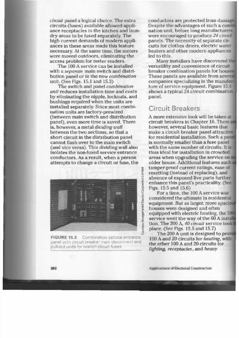
8/19/2019 Applications Electrical
http://slidepdf.com/reader/full/applications-electrical 207/447
circuit panel a logical choic e. The extra
circuits (fuses) available allowed appli
ance receptacles in the kitchen and laun
dry are as to be fused separately. The
high current d em ands of mo dern appli
ances in thes e areas m ade this feature
necessary. At the sam e time, the me ters
were moved outdoors, eliminating the
access problem for meter readers.
The 100 A service can be installed
with a separate main switch and distri
bution panel or in the new com bination
un it. (See Figs. 15.1 and 15.3)
The switch and panel com bination
unit redu ces installation time and cos ts
by eliminating the n ipple, lockn uts, and
bushings required when the units are
installed separately. Since most combi
nation units are factory-prewired
(between m ain switch and distribution
panel) , even m ore time is saved. There
is , however, a metal
dividing wall
between th e two sections, so that a
short circuit in the distribution panel
cannot flash over to the main switch
(and vice versa) . This dividing wall also
isolates the non-fused service entrance
con duc tors. As a result, when a pe rson
attempts to change a circuit or fuse, the
o
U
E
CO
&
FIGURE 15.3 C ombination service entrance
panel with circuit breaker main disconnect and
pull-out units for branch circuit fuses
con duc tors are protected from dam
Despite the advantages of such a
c o
nation unit, before long manufactu
were encouraged to produce 24 ci
panels. The necessity of separate cir
cuits for clothes driers, electric wat
heaters and other modern appliance
led to this.
Many installers have discovered
versatility and convenience of circu
breaker combination panels for hou
Th ese p anels are available from sev
companies specializing in the manu
ture of service equipment. Figure
1
show s a typical 24 circuit combinat
panel.
Circuit Breakers
A more exten sive look will be taken
circuit breakers in Chapter 16. Ther
however, several basic features that
make a circuit breake r panel
attract
for residen tial installation. Such a p
is normally sm aller than a fuse pane
with th e sam e n um ber of circu its. It
th us ideal for installation in crowde
areas when upgrading the service
o
older house. Additional features su
tamper-proof current ratings, ease o
resetting (instead of replacing), and
abs ence of expose d live parts furth
en han ce this panel's practicality. (S
Figs.
15.5
and 15.6)
For a time , the 100 A service wa
considered the ultimate in residenti
equipment. But as larger, more
spac
houses were designed and often
equippe d with electric heating, the
service went the way of the 60
A
in
tion. Th e 200 A, 40 circuit se rvice tc
place. (See Figs. 15.5 and 15.7)
The 200 A unit is designed to pr
100 A and 20 circuits for heating, w
the other
100 A
and 20 circuits for
lighting, receptacles, and heavy
202
Applications of Electrical Con struction

8/19/2019 Applications Electrical
http://slidepdf.com/reader/full/applications-electrical 208/447
E
E
o
u
RES 15.4A and B C ombination service entrance load centre w ith 100 A main breaker
. sion for up to 24 individual circuit breakers. W ith the cover remo ved, the breaker con-
n points can be easily seen .
Upiiances.
With this sy stem, th e elec-
tkc
heating part of some serv ice b oxes
o n be turned off during the sum mer
k o n t h s .
As with
100 A
panels, circuit break-
HB
are pa rt of larger serv ice pa nel s. Fig-
are 15.5 illustrates a 200
A
circuit
beaker
panel.
Even 400
A,
600
A,
or 800
A
services
car. be found in some private resid enc es.
t a t is because larger modern hom es
demand
more circuits and have more
•rea
to heat. The installation of more
more electrical conveniences
•quires
a corresponding increase in
krvice
size.
Installation Techniques
Service entrance eq uipment m ust be
installed in a location suitable to both
the local supply authority and the
inspection department. Supply authori
ties a re usually qu ite willing to visit
homes on request and advise on the
location of service equ ipm ent. C onsulta
tion with them can preve nt installation
of servic e equipmen t in an unac ceptab le
manner; equipment installed contrary to
supply authority standard s must be
removed and reinstalled to their satis
faction. Mast height, meter height and
location, point of entry into the building,
and box location can be selected quickly
by an insp ector on a service location
visit.
Residential Service Wiring

8/19/2019 Applications Electrical
http://slidepdf.com/reader/full/applications-electrical 209/447
bolt -on main
breakers
isolated main breaker
c om par t m ent
branch circuit neutral
t e r m ina l jum per
provis ion fo r 40 c ircui ts
in a com bina t ion of
s ingle- or double-pole
units , inc luding ground
fault protect ion breakers
wire direct ing posts
centre-l ine hole
(t
lower m ount ing s
cable entry locatio
f lat-rate water hea
wi r ing
ma in neutral b loc
easily accessible
bars on each side
panel
gr ound w i r e
conn
terminals on each
panel
branch circuit bre
single-
an d
doub
units f rom
15Ato
rat ings
t in-plated bus-ba
branch circuit bre
connect ion
FIGURE 15.5 Internal features of a comb ination service entrance load centre, 200 A rati
40 circu it capacity, in a total circuit breaker unit
204
Applications of Electrical Construction
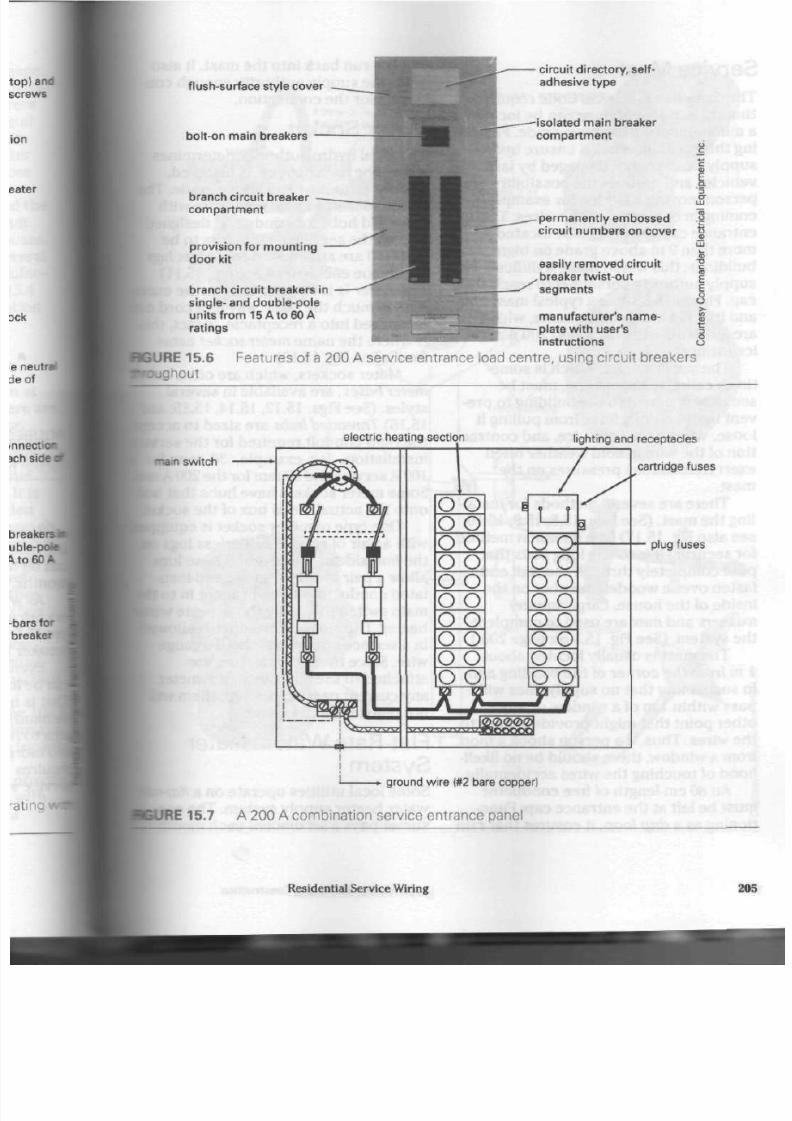
8/19/2019 Applications Electrical
http://slidepdf.com/reader/full/applications-electrical 210/447
f lush-surface style cover
bolt-on main breakers
branch circuit breaker
co mp a r tme n t
provision for mount ing
door kit
branch circuit breakers in
single-
and double-pole
units f rom 15 A to 60 A
ratings
circuit directory,
self-
adhesive type
isolated main breaker
co mp a r tme n t
i
RGURE15.6
•oughout
Features of a 200 A service entrar
permanent ly embossed
circuit numbers on cover
easily removed circuit
breaker twist-out
segments
manufacturer's name-
E
plate wit h user's
?
instruct ions
£
>ad centre, using circuit breakers
electric heating section
-nam switch
lighting and receptacles
cartridge fuses
plug fuses
ground wire (#2 bare copper)
IRE 15.7 A 200 A combination service entrance panel
Residential S ervice Wiring
20

8/19/2019 Applications Electrical
http://slidepdf.com/reader/full/applications-electrical 211/447
Service Mast
Th e Canadian Electrical Code re quire s
that the service entrance cap be located
a minimum of 4.6 m abo ve gra de . Follow
ing this regulation helps ensu re h ydro
supp ly lines are not dam aged by large
vehicles and re du ces th e possibility of a
person moving a ladder, for example,
coming in con tact with the wires. Th e
entrance cap should not be located
more than 9 m above grade on high
bu ildings: th is wou ld m ake it difficult for
supply authority personn el to reach the
cap . Figure 15.8 show a typical ma st u nit
and its individual components, which
are available with 100 A and 200 A serv
ice fittings.
The service m ast, which is som e
times called th e standpipe, must be
securely fastened to the building to pre
vent hydro supply lines from pulling it
loose . Wind, rain, snow, ice, and co ntra c
tion of the wire in cold w eath er often
exert t remendous pressures on the
mast.
The re are several m etho ds for instal
ling th e m ast. (See Figs. 15.8,15.9,15.10;
see a lso Fig.
15.17)
One common method
for sec uring it is to u se long
bolts
that
pass completely through the wall and
fasten over a woo den mem ber on the
inside of the h ou se. Large squ are
washers and nuts are used to co mp lete
th e sys tem . (See Fig. 15.1 on page 200.)
The m ast is usually located abo ut
1 m from t he corn er of the building and
in suc h a way tha t n o supply lines will
pa ss within 1 m of a window o r any
other point that might provide access to
the w ires. Th us, if a pers on shook a m op
from a window, the re sho uld be n o likeli
hoo d of touc hing th e wires accidentally.
An 80 cm length of free co nd uc tor
mu st be left at the e ntra nc e ca p. Func
tioning as a drip loop, it ensu res tha t rain
J
1
will not run back in to the m ast. It al
gives the supp ly auth ority enough C
ductor for the connection.
Meter Socket
The local hydro autho rity determin
wh ere the m eter soc ket is installed,
usually at abou t
1.8
m abo ve grade
m eter socke t, a me tal enclosure wit
threa ded hu bs for conduit, is design
so that th e service cond uctors to b
metered are at tached to solderless
within the enc losure . (See Fig.
15.11
The
meter
is then plugged into th e
sure in much the sa m e way as a cor
is plugged into a rece ptacle .
In
fact.
is whe re the nam e meter socket cam
from. (See Fig. 15.13)
Meter sock ets , which are often
meter bases, a re available in seve ra
styles. (See Figs. 15.12,15.14,15.15,
15.16) T hreaded hubs are sized to a
the rigid conduit required for the s
installation, for example, 30 mm
100 A service and 50 mm for the 200
Some meter sock ets have hubs tha
on to the a ctual metal box of the soc
One type of me ter sock et is
equ
with a pa ir of special sold erless lug
the line side of the socket. These lu
allow a pair of No.
10
gauge,
red-in
lated
cond uc tors to be broug ht in t
main switch to supp ly th e flat-rate
heater . The smallest con du ctor allo
in a service conduit is a
No.
10 gau
wire. Since the se co ndu ctors are
attac he d t o the line side of the m e
any current passing through them
not register on the meter.
Flat-Rate Water Heater
System
Some local utilities op era te on a
fl
water heater supp ly system . The
C
sumer pays a set amount each
m o n
206 Applications of Electrical Construction
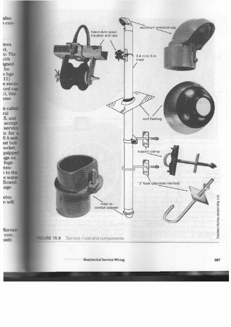
8/19/2019 Applications Electrical
http://slidepdf.com/reader/full/applications-electrical 212/447
I
RE 15.8 S ervice mast and comp onents
Residential S ervice Wiring
207
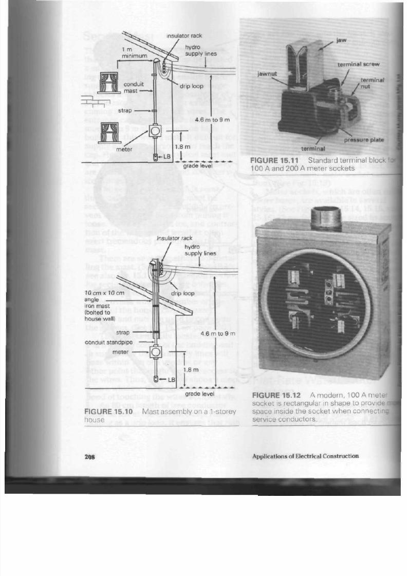
8/19/2019 Applications Electrical
http://slidepdf.com/reader/full/applications-electrical 213/447
insulator rack
grade level
jawnut
terminal screw
terminal
nut
pressure plate
terminal
FIGURE 15.11 S tandard terminal block
100 A and 200 A meter sockets
10 cmx 10 cm
angle
iron mast
(bolted to
house wa
strap
conduit standpipe
meter •
insulator rack
J
hydro
supply lines
I
grade level
FIGURE 15.10 Mast assembly on a 1-storey
house
FIGURE 15.12 A modern, 100 A meter
socket is rectangular in shape to provide
space inside the socket when connectin
service condu ctors.
208
Applications of Electrical C onstruction
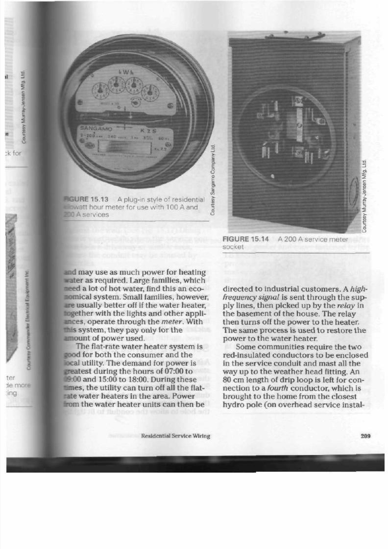
8/19/2019 Applications Electrical
http://slidepdf.com/reader/full/applications-electrical 214/447
2
URE 15.13 A plug-in style of residentia
•att hour me ter for use with
100
A and
A services
"
FIGURE 15.1 4
socket
A 200 A service m eter
and
may use as much power for heating
water as required. Large families, which
aeed
a lot of hot water, find this an eco
nomical system . Small families, however,
are usually be tter off if the water heater,
toge ther with the lights and other appli
ances, operate through the meter. With
•" • s
system, they pay only for the
amount
of power used.
The flat-rate water hea ter system is
food
for both the consumer and the
local utility. The demand for power is
neatest during the hours of 07:00 to
«:00 and 15:00 to
18:00.
During these
Wmes,
th e utility can turn off all the flat-
Bate
water heaters in the area . Power
irom the water heater units can then be
directed to industrial custom ers. A high
frequency signal is sent through the sup
ply lines, then picked up by the relay in
the basement of the house. The relay
then tu rns off the power to the heater.
The same process is used to restore the
power to the water heater.
Some communities require the two
red-insulated conductors to be enclosed
in the service conduit and m ast all the
way up to the weather head fitting. An
80 cm length of drip loop is left for con
nection to a fourth conductor, which is
brought to the home from the closest
hydro pole (on overhead service instal-
Resldentlal S ervice W iring
209

8/19/2019 Applications Electrical
http://slidepdf.com/reader/full/applications-electrical 215/447
FIGURE 15.15 A meter socket assembly for use on a duplex or semi-detached house
lations). This fourth conductor a
the high-frequency signed to one red
wire,
while the second red conducto
connected to one of the incoming si
^ lines for the house . Underground se
installations normally use the meter
f socket with the special lugs.
c
I
{ S ervice E ntrance E lbows
| A 90° corner
is used to bring the
| standpipe from the m eter socket thi
the wall and into the serv ice boxes.
90° bend can be m ade in the service*
duit, but a groove must be chiselled
the wall for approximately
30
cm at
the hole to allow the conduit to fit I
FIGURE 15.16 A n old-style. 60
A /100
A
service meter socket in the original, round
configuration
210
Applications of Electrical Construction

8/19/2019 Applications Electrical
http://slidepdf.com/reader/full/applications-electrical 216/447
meter
NO TE: Wal l must
be grooved.
meter
hole
grade
leve
main switch
RE 15.17 Me thod for driveway
instal
ls of standp ipe (90° bend)
against the wall. (See Fig. 15.17) Doing
his is worthwhile when th e serv ice con-
B at
is in a driveway or similar are a,
ibere the conduit may be abused by
[vehicles.
There is another way of handling the
f
b end . (See Fig. 15.18) It doe s awa y
•ith the need for grooving the wall, but
fee standpipe protrudes from the wall a
lew extra inches (several centimetres),
[his goose-neck
bend m ethod of enter-
kg the building was o nce u sed widely.
WUh the increase in condu it size and the
•welopment of condulet fittings, how-
• w , this difficult bend has become less
popular.
A condulet fitting, su ch a s th e LB, is
approved for use where there is little
iiance of mech anical injury crack ing
he
casting. (See Fig. 15.19)
The hole in the wall must be m ade
•ghtly
larger to allow the sh ort arm of
main switch
FIGURE 15.18 A lternative me thod for drive
wa y installation of standpipe (goose-neck
bend)
the cond ulet to ente r the wall. A weath
erproof
gasket
and
cover
fastened to the
LB seal out any mo isture. The LB fitting
provides access to the conduit and
mak es it easie r to pull in the large con
duc tors required for modern h ouse s.
A special fitting called the service ell
can a lso be used for ente ring a building.
(See Figs. 15.20 and 15.21) Its main
advantage is that the short arm does no
extend in to th e wall. Because the hole in
the wall does not need to b e made any
larger than th e conduit nipple, this ty pe
of installation is more weatherproof than
other types.
No m atter which metho d is used to
enter the building, the Canadian Electri
cal Code requires tha t all open ings
around the area where the conduit
en ter s th e wall be filled. Otherw ise,
there may be water damage to the h ouse
Residen tial Service Wiring
21

8/19/2019 Applications Electrical
http://slidepdf.com/reader/full/applications-electrical 217/447
meter
meter
main sw itch
FIGU R E 15. 19 L B
condulet
met hod f or
enter ing bui ld ing
F I G U R E 1 5 . 2 0
and gasket
Serv ice el l f i t t ing wi th cover
and/or the service equipment.
Mortar,
or
a similar material, trowelled into place
will sto p m oisture o r cold air from com
ing in.
212
main switc
FIG URE 15.21 A serv ice el l instal lat ion
Underground Service
Most new subdivisions have under
ground service installations to help
stree ts look neat and uncluttered,
distribution transformer can be l
under ground in a transformer vault
on a conc rete p ad. The vault or pad
be out near the street o r behind the
house, with the supply lines coming
under the backyard. (See Fig. 15.22)
er-
elp
I.
T
oca
lul
L ocation o f S ervice Box
i
ection 6 of th e C anadian Electrical
lists the p laces where service boxes
must not be locate d. In general, serv
boxes shou ld be m ounted on a wall
abo ut 1.5 m above th e floor and as |
as possible to the point where the
I
ice cond uit en ter s t he building. If the
is any doub t ab out w here to install
box, the local inspection authority
should be asked for advice.
Applications of Electrical Construction

8/19/2019 Applications Electrical
http://slidepdf.com/reader/full/applications-electrical 218/447
pA^ - j
Side View
Front View
doc
meter
socket
BGURE 15.22 Und erground service installation (front and side view s)
Residential Serv ice Wiring 213
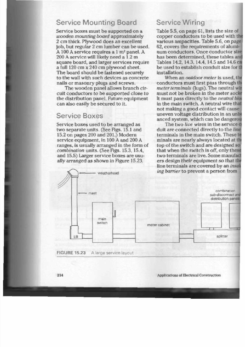
8/19/2019 Applications Electrical
http://slidepdf.com/reader/full/applications-electrical 219/447
S ervice M ou nting Board S ervice W iring
Service boxes must
be
suppo rted on
a
wooden mounting board approximately
2 cm thick. Plywood d oe s an exce llent
job,
but
regular
2
cm lumber can be used .
A 100 A service requires a i m
2
panel. A
200
A
serv ice w ill likely need
a 1.2
m
squ are board, and larger service s require
a full 120 cm x 240 cm plywood shee t.
The board should be fastened securely
to the w all with such devices as concrete
nails
or
ma sonry plugs and screw s.
The wood en panel allows bran ch cir
cuit con duc tors to be sup po rted close
to
the distribution p anel. Future equ ipmen t
can also easily be sec ured to it.
Service Boxes
Service boxes use d
to be
arranged
as
two sepa rate units. (See Figs. 15.1 and
15.2
on
pag es 200 and 201.) Modern
service equipment, in 100 A and 200 A
rang es, is usually arran ge d in th e form of
combination u nits. (See
Figs.
15.3,15.4,
and 15.5) Larger servic e boxe s are usu
ally arran ged as show n in Figure
15.23.
weatherhead
mast
n
LB
J
main
switch
Table 5.5,
on
page
61,
lists the size
copper conductors
to
be used wit
vario us a mp acities. Table 5.6, on p
62,
covers the requirements
of
alu
num condu ctors. Once condu ctor
has been determined, these tables
Tables 14.2,14.3,14.4,14.5 and 14
be used to establish c ond uit size
installation.
When an o utdoor meter is used
conductors must first pass throug
meter terminals (lugs). The neutra
m ust not be broken in the m eter
S
It must pa ss directly to the neutra
in the main switch. A neutral w ire
not m aking
a
good co ntac t will ca
uneven v oltage distribution
in an
anced system, which can be dang
The two live wires in the servi
duit are conn ected directly to the
terminals in the m ain switch. Thes
minals are nearly always located a
to p of th e switch and are designed
that when the switch
is
off, only th
two terminals are live. Some manu
ers design their equipm ent so tha
line terminals a re covered
by an
ing barrier
to
prevent
a
perso n fro
combinatio
sub-disconnec
distribution
pa
meter cabinet
splitter
F I G U R E 15.23 A l a r g e s e r v i c e l a y o u t
214
Applications of Electrical Construction
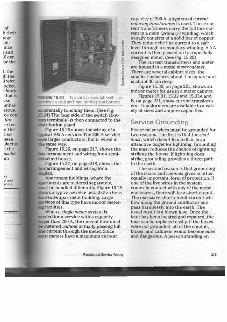
8/19/2019 Applications Electrical
http://slidepdf.com/reader/full/applications-electrical 220/447
E
o
U
Q
RGURE 15.24 Typical main switch with line
nals at top and load terminals at bo ttom
accidentally touching them. (See Fig.
4) The load side of th e switch (b ot
tom terminals) is then connected to the
distribution panel.
Figure 15.25 sho w s th e wiring of a
Typical 100 A service. The 200 A service
•ses larger con du cto rs, but is wired in
the sam e way.
Figure 15.26, on pa ge 217, shows the
box arrangement and wiring for a semi-
ietached
house.
Figure 15.27, on p age 218, show s th e
»x arrang em ent and wiring for a
p p l e x .
Apartment buildings, where the
•>artments are metered separately,
•ust be handled differently. Figure 15.28
sho w s a typical servic e installation for a
bur-su ite apartm ent building. Large
Krvices of this type h ave indo or meter-
tag facilities.
When a
single-meter
system is
eded for a service with a ca pac ity
•rger
than 200
A,
th e curre nt flow m ust
be metered
without
actua lly pa ssing full
•oe
current through the m eter. Since
nost meters have a maximum current
cap acity of 200 A, a system of current-
reducing transformers is used. The se cur
rent t ransformers carry the full line cur
rent in a main (primary) winding, which
usually cons ists of a solid ba r of cop per.
They red uce th e line curren t to a safe
level through a secon dary winding. A 5 A
curren t is then p assed on to a specially
designed meter. (See Fig. 15.29)
The current t ransformers and me ter
are house d in a metal meter cabinet.
The re are several cabinet sizes: the
smallest mea sures about
1
m squa re and
is abo ut 30 cm d eep .
Figure 15.30, on pa ge
221,
shows an
indo or m eter for use in a m eter c abine t.
Figures
15.31,15.32
and
15.33Aand
B, on pag e 221, show current transform
ers.
Transfo rme rs are available in a vari
ety of sizes and a m pere capa cities.
Service Grounding
Electrical services m ust be groun ded for
two reasons. The first is that the steel
mast, which rises 4.6 m to 9 m, is an
attractive target for lightning. Grounding
the mast reduces the chance of lightning
striking the house.
If
lightning d oe s
strike, grounding provides a direct pa th
to the earth .
The seco nd reason is tha t grounding
of the boxes and cabinets gives another,
equally imp ortant, form of protection . If
on e of the live wires in the system
com es in con tact w ith any of the metal
enc losu res, the re will be a sho rt c ircuit.
The exc essive short-circuit curren t will
flow along the ground con du ctor and
pass harm lessly into the earth. The
usua l result is a blown fuse. On ce th e
fault has been located and repaired, the
fuse ca n b e repla ced easily. If the box es
were
not
gro und ed, all of the condu it,
boxes, and cabinets would beco me
alive
and dangerous.
A
person standing on
Residential Service Wiring
215
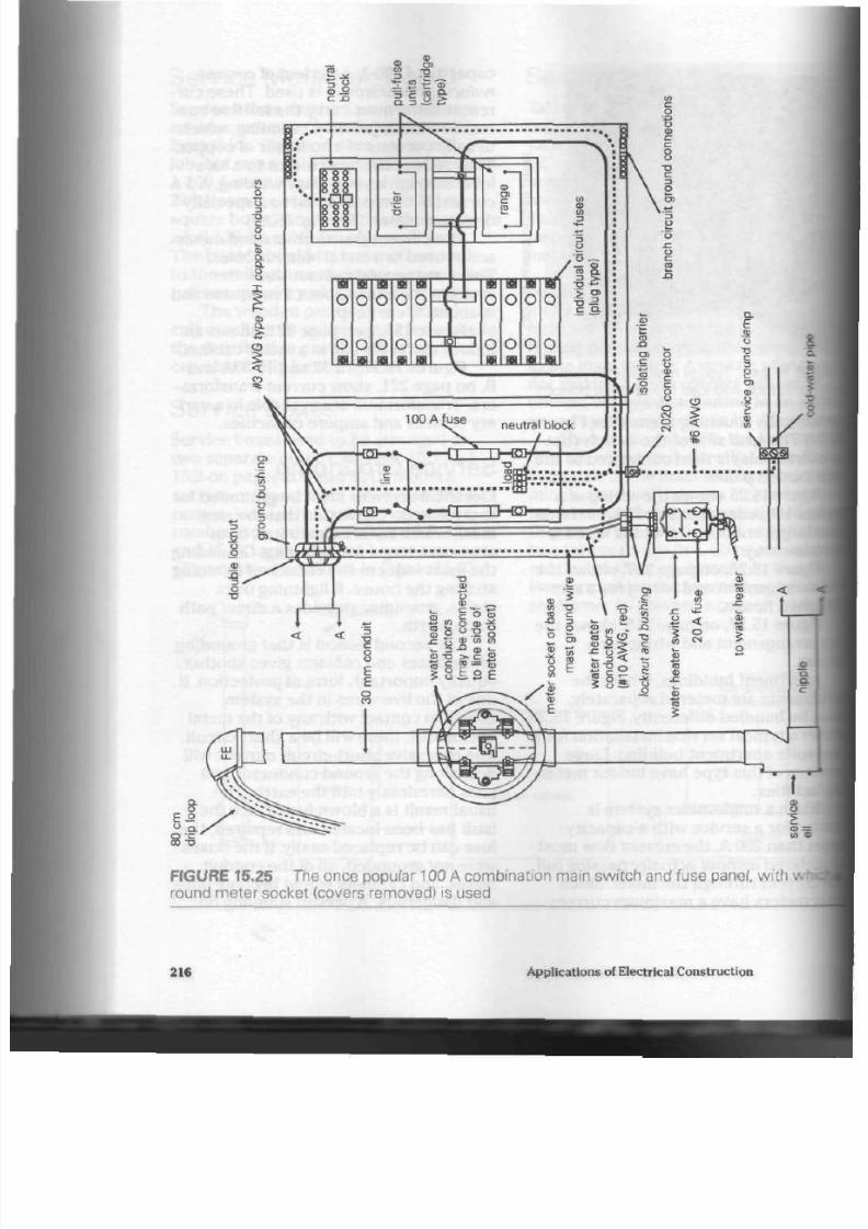
8/19/2019 Applications Electrical
http://slidepdf.com/reader/full/applications-electrical 221/447
FIGURE 15.25 The once popular 100 A combination main switch and fuse panel, wi th w
round meter socket (covers removed) is used
216
Applications of Electrical Con struction

8/19/2019 Applications Electrical
http://slidepdf.com/reader/full/applications-electrical 222/447
•Based on copper conductor sizes
#3/0
RW-90*
mast
50
mm conduit
double meter base
#6 bare"
to ground clamp on water pipe
URE 15.26 Semi-detached house service installation
loist earth or a damp floor and touch-
tag
part
of
the metallic system would
Kceive
a
120 V
sho ck. In a large b uilding,
•ith no blown fuse on
an
ungrounded
Rrstem,
the fault m ay not sho w up for
m e time and then be almost impossi
ble to locate.
The most common method
for pro-
tatng a ground for a residential service
\
to connect
a
conductor
from
the
mitral block in the main switch
to
the
Bid-water supply pipe as it com es out
I fcom he basement floor. The neutral
[Mock is con necte d to the sw itch bo x by
a brass
bolt.
Thu s, both the box and neu
tral conductors are grounded. The
ground clamp must be fastened on to
the water pipe ahead
of
the meter,
because a leak-proof compound (a non
conductor
of
curren t) is applied to the
plumbing threads before assembly. (See
Fig. 15.34
on
page 222.) The groun d wire
from t he main switch b ox is usually b are
copper
or
covered with
a
white insula
tion. Table
16.1,
on page
231,
lists the
conduc tor size
to be
used.
When a house ha s
copper
plumbing,
which is properly soldered at the fit
tings,
the ground wire can
be
run from
the main switch to the closest cold-
water pipe. The hot-water tank interferes
with the electrical continuity of the hot-
Residential Service Wiring 217
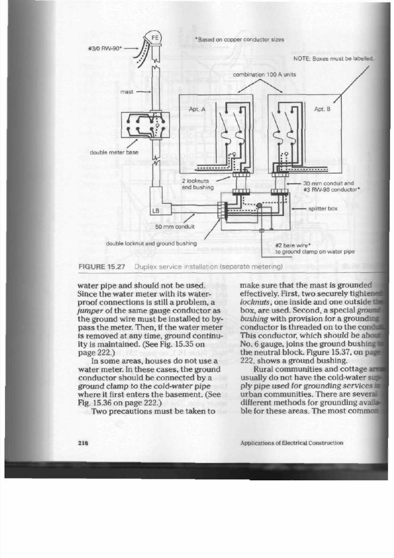
8/19/2019 Applications Electrical
http://slidepdf.com/reader/full/applications-electrical 223/447
#3/0 RW-90*
/
double meter base
'Based on copper conductor sizes
N O T E :
Boxes must
be labelled
combination
100 A
units
rVl
•
•
• • • • |i J pi
~
11,1 I*
b~
30 mm conduit and
#3 RW-90 conductor*
splitter box
50 mm conduit
double locknut and ground bushing
#2 bare wir e*
to ground clamp on water pipe
FIGURE 15.27 Duplex service installation (separate metering)
water pipe and should not be u sed.
Since the water meter with its water
proof connections
is
still
a
problem,
a
jumper
of the same gauge conductor as
the ground w ire must be installed to by
pass t he m eter. Then, if the water meter
is removed at any
time,
ground continu
ity is mainta ined. (See Fig. 15.35 on
pag e 222.)
In some areas, hou ses
do
not u se
a
water m eter. In the se ca ses, the ground
conductor should be connected by a
ground clamp to the cold-water pipe
where it first en ters th e basem ent. (See
Fig. 15.36 on page 222.)
Two precautions mu st be taken to
make sure tha t the m ast is grounded
effectively. First, two secu rely tight*
locknuts, one inside and one outside
box, are used. Second,
a
special groi
bushing
with provision for a
groundii
conduc tor is threaded on to the com
This conductor, which shou ld be
at
No.
6 gauge, joins the g round bushir
th e neutr al block. Figure 15.37, on
]
222,
shows a ground bushing.
Rural communities and cottage i
usually do not have the cold-water
su
ply pipe used for grounding services
urban comm unities. There are sever
different methods
for
grounding avai
ble
for these areas. The most
commo
218
Applications of Electrical Construction

8/19/2019 Applications Electrical
http://slidepdf.com/reader/full/applications-electrical 224/447
a
re
3
3
00
a.
"
500
MCM
RW-90
w
00
>
" O
Co
3
3
C D
r-*
CO
CD
5
o
CD
5 '
en
o '
cT
CD
"a
cu
Q>
CD
3
CD
C D
5 '
CQ
Based on copper conductor sizes
T o A p t . 4
double locknut
a n d g r o u n d b u s h i n g
#2/0 bare
400 A spli t ter box
double locknut and bushing ( throughout )
to ground c lamp on water p ipe
NO TE: Boxes must be label led.

8/19/2019 Applications Electrical
http://slidepdf.com/reader/full/applications-electrical 225/447
E
o
a
s
c
m
-»
>
CD
3
CD
« -
t t >
13-
Q)
3
CD
0 1
CD
<
o '
CD
3 '
en
3
5T
-*
o
3
100 A combinat ion pane
200 A combination panel
80 cm drip loop
500 MCM
RW-90
#3 RW-90 —
A — i
9 0 m m
mast conduit
400 A main switch
400 A splitter box
NOTE: Lighting panel wired similar to heating
panel. Use #3/0 RW-90*.
"Based
on copper conductor sizes
1m x 1 m meter cabinet
I
t l / ~
p r i m a r /
: rf ch_j
" " ; s e c o n d a r y ^ .
double locknut and ground bushing
# 2 / 0 b « r t "
double locknut and bushing (throughout)
ti i u
1
" ' ' IMUI|I ' in wii lni | i i | i i*
^—A
90 mm conduit nipple
500 MCM RW-90
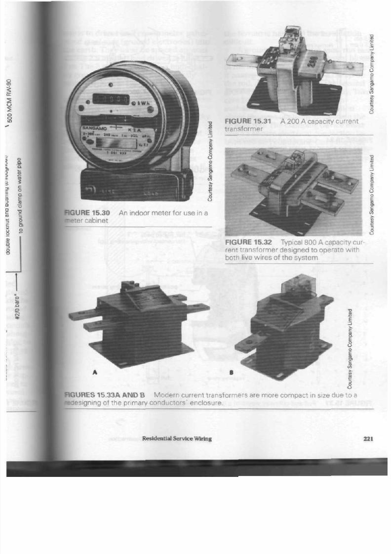
8/19/2019 Applications Electrical
http://slidepdf.com/reader/full/applications-electrical 226/447
.
l
FIGURE 15.31
transformer
A 200 A capacity current
£
o
U
FIGURE 15.30
^Her
cabinet
An indoor meter for use in a
FIGURE 15.32 Typical 800 A capacity cur
rent transformer designed to operate w ith
both live wires of the system
3
8
FIGURES
15.33A
A N D B Mod ern current transformers are more compact in size due to a
•designing
of the primary conductors' enclosure.
Residential S ervice W iring
22
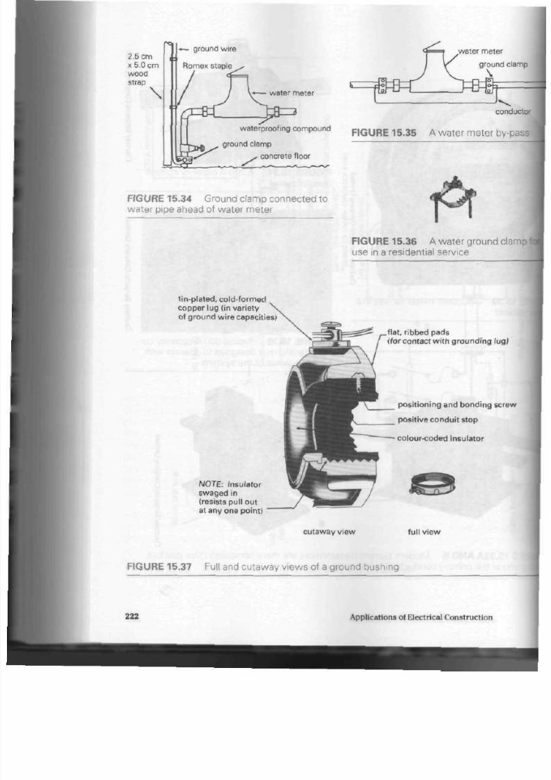
8/19/2019 Applications Electrical
http://slidepdf.com/reader/full/applications-electrical 227/447
2.5 cm
x 5.0 cm
wood
strap
\
«— ground wire
Romex
staple
water meter
waterproofing compound
ground clamp
>»
concrete floor
FIGURE 15.34
Ground clamp connected to
water pipe ahead of water meter
ground clam
conduct
FIGURE 15.35 A wate r meter by-pas
FIGURE 15.36 A water ground cla
use in a residential service
t in-p la ted, cold- formed
copper lug ( in variety
of ground wire capacit ies)
N O T E :
Insulator
swaged in
(resists pull out
at any one point)
f lat, r ibbed pads
(for contact wi th grounding lug)
posi t ioning and bonding screw
posit ive conduit s top
colour-coded insulator
cutaway v iew
ful l v iew
FIGURE 15.37 Full and cutaway views of a ground bushing
222
Applications of Electrical Construction

8/19/2019 Applications Electrical
http://slidepdf.com/reader/full/applications-electrical 228/447
is to drive tw o 2 cm diam eter,
galva-
red steel rods (ground ele ctrode s) into
e earth . They must be sp aced approxi-
itely
2.5 m apa rt an d driven in a full
a.
The 3 m depth ensu res a high-qual-
ground contact with permanently
1st ea rth . (See Fig. 15.38)
Commercial
ground rod drivers
are
available, but most often a sledge
wnmer is used to drive rods into the
prth. Layers of clay and stones or rocky
rr ra in are problems to the installer.
Sometimes the rods , striking a layer of
lack, gradually turn and m ove back to
be surface, several metres from the
farting point. Inspection authorities
w rods to be driven in on an ang le If
the terrain is hard and the installation
difficult.
A grounding con ductor must run in a
continuous length
from th e neutral b lock
in the main switch to the first rod. Here
it passes unbroken through a clamp on
the rod, and then travels to the sec ond
ground electrod e som e 2.5 m away. Take
care to check with the inspection
authority for up-to-date information
about the typ e of clamp allowed on th e
ground rod. The clamping device m ust
make a secure electrical connection to
both rod and conductor. Once the rods
and ground conductor are covered with
earth, it may be many years before the y
are checked again.
HGURE 15.38 Ground rod installation
Residential Service Wiring

8/19/2019 Applications Electrical
http://slidepdf.com/reader/full/applications-electrical 229/447
In rocky soil, it may be impossible to
drive in ground rods. In these cases, a
steel plate, 0.2 m
2
in area and
a
minimum
of 6 mm thick, can be buried
in the
earth . The plate should be installed as
deeply as possible to ensure a good
grou nd co nta ct. (See Fig. 15.39)
There are also other m ethod s
of
pro
viding a ground circuit under rugged ter
rain con ditions. A pair of ground rods
can be laid in a trench , dug as deeply as
the rocky terrain will permit, an d th en
cov ered w ith to p soil. Still an oth er
method requires a ground rod or copper
conductor to be buried or encased
within the concrete footings supporting
a bu ilding's walls. Sufficient co nd uc to r
size and length sho uld be provided to
make
a
con nection to the m ain n eutral
block within the m ain service discon
nect. Consult Section 10.700
of
the Elec
trical Code
for
co nfirmation
of
ground
ing technique s in difficult ar ea s. (Se
Fig. 15.40)
Often, when g roun d rod s (artific
grounding) are used, inspection
aut
ties require a grounding conductor o
least No. 8 gauge to be run from the
tral
block of the main switch to a
cl«
on the cop per p lumbing. This
happ
most often in rural com mu nities to
vent the chance of a voltage differer
existing between the earth and the
plumbing system in
the
ho use . If a
|
tic (PVC) w ater sy stem
is
used
thro
ou t the hou se, this extra ground cor
tor is not required.
Meters
The meter records the num ber
of
k
wa tt ho urs (1 kW is equal to 1000 V
power consumed. Modern meters
g
direct reading
the way odom eters do
»
."
0
ground w ire to service disconnect
6 m m
» »
rock layer
•^
o •
0-
NOTE:
Buried 25 cm below
permanent moisture level
O
F I G U R E 1 5 .3 9 P l a te e l e c t ro d e g r o u n d i n g m e t h o d
224
Applications
of
Electrical Construction

8/19/2019 Applications Electrical
http://slidepdf.com/reader/full/applications-electrical 230/447
main service
equipment
ground cable sized to
match service requirements
1/2 in. /1.25 cm steel rod or 20 ft. / 6 m of copper cable
basement
wall
- > " ^
^ t o . L wall foot ing
5 cm poured concrete
clamp
1 0 f t . / 3
m
long
I
SURE 15.40 A rt if icial ground electrode system
» s . (See Fig. 15.30) Th ere a re still many
l*-fashioned me ters in use, however,
fcese
meters have
five small dials
to
tamcate the co nsu m ption . (See Fig.
141) Moving from right to left ac ro ss
e dials, the first dial shows single
• t s . the second tens, the third hun-
keds, the
fourth
thousa nds, and the
fifth
a s of tho us an ds . Figure 15.42 sho w s a
be-dial meter reading.
The consumer pays the local utility
W
power at a rate of so m any cen ts
per
btvatt hour. The num ber of kilowatt
•nrs
of power used during a given
period is read from th e m eter. The nu m-
s is
multiplied by th e ra te pe r kilowatt
•or. and the customer is billed.
Note: Many utilities have a rate
structure whereby th e price charged a
E
3
Q
o
E
£
2
FIGURE
15.41
Five-dial me ter
Residential Service Wiring

8/19/2019 Applications Electrical
http://slidepdf.com/reader/full/applications-electrical 231/447
10 000
1 000
FIGURE 15.42 A five-dial meter reading (26 422
kW»h)
customer varies according to the
amount of power con sum ed. For exam
ple, the first 50 kW-h would be at a
base price, while the next 200 kWh
would be charged a t a lower rate pe r
kilowatt hour. This system rewards the
con sum er using a lot of electrical
energy, such as an electric heating cus
tomer. It makes electricity more com
petitive with other fuel ty pe s.
Temporary Service
On construc tion s ites power is needed
for portable drills, saws, concrete
mixers, and othe r equipm ent. A tempo
rary service is usually erected on a pole.
(See Fig. 15.43) Th is unit is desig ned
with a main switch, a small distribution
panel, several duplex receptac les, and a
weathe r-resistant cabinet to protec t it.
Mast height can b e as low as 4.6 m.
A
sin
gle ground rod is usually enough for th is
type of installation. Often, the local util
ity ch arg es a flat rat e or fee for serv ice,
and a meter is not installed.
Inspection Permit
An application for inspe ction must be
filed with th e local inspection auth ority
for a ll new installation s of electrica l
equipm ent. A residential serv ice is con
sidered an important installation and
receives careful attention from the
inspec tion authority. Power will not usu
ally be allowed o n until th e ins pec tor is
satisfied that every detail is comp
and safely installed. This inspectio
important, because it guarantees
owner and the insurance compan
every precaution h as been taken
sur e a safe and high-quality instal
F o r R e
v
i
e
m
ii
1. What are th e two main
meth
for bringing the 3 wire distrib
system to a house?
2. List the main pa rts of a con
sumer's service.
3.
Why did the 60 A service be
inadequate for modern hous
Give two reas on s.
4. W hy are combination servic
panels often used in modern
houses?
5. What are the minimum and
m
mum heights for service entr
fittings? Why?
6. Describe a
drip loop,
and
exp
its purpose.
7. What is the
m eter base?
How
above grade is it m ounted?
8. Why is the flat-rate water hea
system good for both the
ho
owner and the public utility?
9. Describe the two different
methods for supplying curren
flat-rate wa ter-hea ter system
226
Applications of Electrical Co nstruction

8/19/2019 Applications Electrical
http://slidepdf.com/reader/full/applications-electrical 232/447
25 mmconduit mast
f— NOTE:
Minimum height
4 m
#6 TW H copper conductor
-•—
conduit strap
2 pole, plug fuse units
"U '
ground duplex
receptacle .-
protect ive wood
'enclosure
fc5i« -~
hasp
- 60
A
main switch
max level
•*•-**••»••*•
5 cm x 10 cm
wood brace
#6 bare
or white
ground wire
ground rod
and clamp
NO TE : Suggested depth
1 m —*;
RGURE
15.43
T emporary service installation
Residential Service Wiring 227

8/19/2019 Applications Electrical
http://slidepdf.com/reader/full/applications-electrical 233/447
10. Where are cast aluminum condu
cts a pproved for use? Why?
11. How is moisture stopped from
seeping in where a service conduit
ente rs a wall?
12. Whe re in th e Can adian Electrical
Code is information about the size
of service conductors and con
duit?
13.
What dang er exists if th e neutra l
wire of the 3 wire system is
accidentally broken or loosely
connected?
14. Explain why current transformers
are used with a service larger than
200 A.
15. List two rea son s for groun ding an
electrical service.
16. Why are services that have w ater
meters grounded ahead of the
water meter?
17. How is a servic e grou nded when a
house has copper plumbing
throughout?
18. Where in the Canadian Electrical
Code is information abo ut th e size
of ground w ire to be used on a res
idential service?
19.
What two precautions must be
taken when grounding a service
mast?
20. Describe in your own words two
different methods for grounding a
service in a rural community
where there is no municipal water
supply system.
21 .
Why are plastic bushings or metal
bushings with plastic liners used
on service conduits?
22.
Why is electrical inspection impor
tant to the home-owner?
228 App lications of Electrical Con struction

8/19/2019 Applications Electrical
http://slidepdf.com/reader/full/applications-electrical 234/447
S
mall factory and co mm ercial build
ings are sometim es equ ipped with
e 120 V/240 V service used in residen-
hfal installations. The larger capacity
fi V/240 V serv ices (400 A, 600 A, and
I A)
have more than enough circuits
the lights, receptac les, and m otors
hese
small, limited production facilities
Industrial
buildings usually have
ior-driven equipment. These m otors
Men need far more cu rrent than lighting
:uits. When being started, a mo tor
iws thr ee to five tim es' its norm al
crating
current, which places an even
^eater load on the service eq uipme nt. A
•otor
designed to oper ate on a higher
poltage will pro du ce th e sa m e am ount of
power but with a dec reas e in line cur
rent. For example, a 750 W motor opera
ting at 120 V will require approx imately
[K
A. The same m otor, internally con
nected to o pe rat e on 240 V, will re quire
about
8 A.
Motors and equipment designed to
•perate
on even higher voltages need
Mill less current. When the current is
•educed, the
w ire size
in th e motor
bin din gs can also be reduced. This
H o w s ,
for example, a 550 V motor to be
•uch sm aller in size tha n a 750 W, 120 V
Motor.
Special voltage systems are available
tor commercial and industrial use . Thes e
Industrial
Services
are known as polyphase (3 phase) sys
t ems . Three-phase motors and equip
ment are more efficient and smaller in
size and usually need less curre nt than
equivalent units designed for use with a
single-phase
supply system.
Three-phase voltages are produced
by the alternators (AC gene rators) at the
power station and can be transformed
by the consum er to any on e of thre e
comm on voltage levels. The m ost p opu
lar 3 ph as e voltage levels are
550 V,
440 V, and 208 V.
The 550 V and 440 V systems use 3
live wires without a neutral condu ctor.
The 208 V system is available in 3 wire
(3
live
con duc tors) and 4 wire (3 live and
1 neutral conducto r) com binations. The
adv anta ge of the 4 wire, 208
V
system is
that there are 120 V between the n eutral
con duc tor an d any one of the three live
con duc tors for lighting and receptac les.
(See Figs. 16.1 and 16.2)
Ano ther advantage of the 3 phase
system is that motors can be reversed
easily. A polyphase motor will rotate in
the opposite direction if any of the three
live wires are interch anged . To reve rse a
single-phase motor, the motor often has
to be dismantled and the internal con
nection of the windings changed.
When w orking on a 3 ph ase service,
take care not to interchange any of the
live
wires.
If the live wires are interchanged,
Industrial Services
229
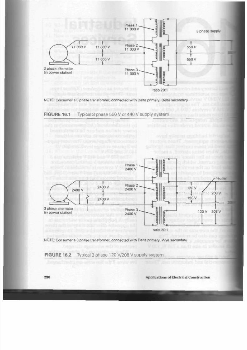
8/19/2019 Applications Electrical
http://slidepdf.com/reader/full/applications-electrical 235/447
Phase 1
11
00 0
V
11 000 V 11 000 V
Phase 2
11
000 V
11
000 V
I
3 phase alternator
(in power station)
Phase 3
11 000 V
a
0
D
3
0
3
I
1
J o
0
a
0
3
0
>
1
3 phase supply
t
550 V
* a
1
550 V
I
ratio 20:1
NOTE: Consumer's 3 phase transformer, connected with Delta primary, Delta secondary
FIGURE 16.1 Typical 3 phase 550 V or 440 V supply system
f
\ 2400 V
1 1 V v
3 phase alternator
(in power station)
r;
>
2400 V
t
2400 V
1
Phase
1 ^
2400 V
Phase 2
2400 V
Phase 3 ^
2400 V
»-a
I — _ s
« i
c
0
r
4
0
^ ^ » * p
o
0
0
o
o
o — 4
neu:r=
120V
•-4
120 V
_ i
120 V 20 8 V
ratio 20:1
NOTE: Consumer's 3 phase transformer, connected with Delta primary, Wye secondary
FIGURE 16.2 Typical 3 phase 120 V/208 V supply system
230
Applications of Electrical Construction

8/19/2019 Applications Electrical
http://slidepdf.com/reader/full/applications-electrical 236/447
wry mo tor in the building will hav e its
Irection of rotation rever sed. For this
as on , high-voltage, 3 ph ase conduc-
JTS are often identified with red, white,
•d blue tags.
•0
V and 440 V S ystems
1550 V and 440 V 3 wire services are
Bed p rim arily
for
mo tors and their con-
pis . The meter is located within the
•Iding in a metal meter cabinet. These
ase services are available in sizes
•ging from 100 A up. The switch boxes
d distribution panels have terminals
^rthe
thre e live wires,
but not for a
neu-
•I
conductor, since the re
is
no neutral
Iductor.
Conductor and c onduit sizes are cho-
i in the sam e way as for the residen-
I
service. Also, ma st h eight, bo x
it, and location are the sam e as for
tsidential ser vice . Figure 16.3 show s a
:al 550
V
and /or 440
V
service instal
lation. The th ree live condu ctors are
often all the same colour, usually black,
red, or blue.
Grounding is limited to the boxes,
cabin ets, panels, and conduits of the sys
tem. A ground conductor is placed between
the ground ing lug in the main switch box
and th e cold-water supply pipe. Table
16.1 lists ground co nd uc tor sizes.
600 V/347 V S ystem
Fairly rece nt in origin, the 600 V/347 V
system is being use d increasingly in
comm ercial lighting and for mo tor and
equipm ent circuits. A Wye connected
secondary, formed by the joining of one
end
of
each
of
the thr ee seco nda ry coils
into
a
comm on point known
as
centre
tap,
provides 600 V betw een any two of
the three
live
wires. The com mon
or
cen
tre tap conductor provides a voltage of
approximately 347 V between itself and
any one
of
the thr ee live wires.
Figure 16.4 show s internal conn ec
tions
of
the m eter ca binet.
TABLE
16.1
Minimum Size of Grounding Conductor for AC
Systems or Common Grounding Conductor
A m p a c i t y of L argest
S ervice C onduc t or
or
Equivalent
f or Mul t ip le Conduc t ors
Size of
Copper Grounding
Conduc t or
AWG
100 or
less
101 to 125
126 to 165
166 to 200
201 to 260
261 to 355
356 to 475
Over 475
8
6
4
3
2
0
00
000
NOTE:
T he ampacity of the largest service conductor, or equivalent if multiple conductors are
used,
is
to be determined from the appropriate Code Table taking into consideration the number of con
ductors and the type of insulation.
Industrial S ervices
231

8/19/2019 Applications Electrical
http://slidepdf.com/reader/full/applications-electrical 237/447
B
•o
E
o
o
§
I
n
o
3
c
30
m
—*
to
-<
-o
o'
9L
CO
"D
3 "
CO
CO
CD
Oi
CJ1
o
<
o
J
o
<
CO
CD
§
o
CD
5 '
CO
*»•
c o _
QT
r-*
o
3
drip loop
machine shop*
•Each switch must be labelled.
compressor*
sub-disconnect switch •—•
mast
from meter cabinet
2 locknuts and 1 bushing (throughout system)
1.2 m x 1.2 m meter cabinet
splitter box
NO TE : 1 wire to each terminal block
2 locknuts and
ground bushing
fuses •
ground wire for mast
Uttra
nipple
voltage coil
#10AWG
wire
V *WTTO» I
de
i * .
j _
current
coil
ground
\
X
. ?
X
?
I V c u r r e n t
I transform
ransformer
meter
teaser (to activate voltage coils)
i
*—
-jf
—
tospl
litter

8/19/2019 Applications Electrical
http://slidepdf.com/reader/full/applications-electrical 238/447
Meter ing
fbe 3
pha se system nee ds a special
•eter,
containing two voltage and two
««rrent
co ils, for reco rding p ow er. This
•Dit
is like two m ete rs in one . Th e to tal
•nount
of power use d is equa l to the
mm
of both me ter section s. (This total
is
shown as a single reading on the
tastrument's dials.) (See Fig. 16.5)
Cur-
tent transformers are used with the 3
phase m eter. (See Figs. 16.6 and
16.7)
A
pec ial 3 phase "hybr id" meter combin-
g mechanical and electronic features is
, on occ asion , for multifunction
metering of large industrial loads. (See
Fig. 16.8)
M etho d of Distribution. As Figure 16.3
show s, the service con duc tors enter a
splitter box
after leaving th e m eter
cabinet.
Sub<lisconnect switches
are then
joined to th e splitter. Co ndu ctors of the
sam e ampacity rating as the disconnec t
switch the n distr ibute 3 phase supply to
various pa rts of the building. Each
sub-disconnect must b e labelled
correctly to show exactly which area or
what equipment it controls.
1.2
m
x 1.2 m meter cabinet
JURE 16.4 C urrent transformers and meter connections for a 3 phase, 600 V / 347 V
vice installation
Industrial Services

8/19/2019 Applications Electrical
http://slidepdf.com/reader/full/applications-electrical 239/447
FIGURE 16.5
A 3 phase meter
o
u
FIGURE 16.7 C urrent transfo
r
mer
FIGURE 16. 6 A 3 phase kilowatt-hour
meter for use with current transformers
A second
disconnect switch is usu
ally mounted on or near the equipment.
Designed so that padlocks can be placed
on it, this switch serves as a safety meas
ure.
The padlocks keep the switch out of
service until personnel are clear of the
machine. Each padlock is removed as |
each person completes service. Whea
the last padlock has been removed,
ice may be restored safely.
Grounding. 550 V will both severely
shock a person and cause serious b
As a rule, none of the 3 phase 550 V a
440 V conductors are grounded. This
isolated system prevents a person in j
contact w ith grounded equipment frca
being injured if and when a live
conductor is also touched. Many
services are equipped with three
indicating lights
(ground detectors)
to
warn that a live conductor has
come •
con tact w ith a m etal box or associated
piece of equipm ent. All metal boxes,
panels, conduits, and fittings, howeve^
are grounded.
Take great care when working vtm
550 V or 440 V system, because all thn
conductors are alive and
dangerous
Sometimes current leaking from faultj
equipment establishes a partial gro
on one conductor. In these
cases,
any
protection given by the system being
isolated is gone.
234
Applications of Electrical Construc tion
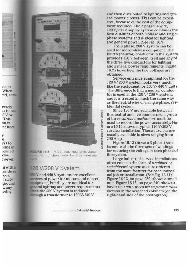
8/19/2019 Applications Electrical
http://slidepdf.com/reader/full/applications-electrical 240/447
E
o
u
31
a
S
iURE 16.8 A3 phase, mechanical/elec-
K mu ltifunction m eter for large industrial
L20 V/208 V S ystem
0
V
and 440
V
system s are excellent
purees of power for motors and related
pripment, but they are not ideal for
pieral
lighting and power requirem ents,
ften
the 550
V
system is reduced
rough a transformer to
120
V/240 V,
and then distributed to lighting and gen
eral power circuits. This can b e expen
sive, becau se of the c ost of the equ ip
ment required. The 3 ph ase, 4 wire,
120
V/208
V
supply system com bines the
best qualities of both 3 phase and single-
phase systems and is ideal for lighting
and gen eral power. (See Fig. 16.9)
The 3 phase , 208 V system can be
used for motor-driven equipm ent. The
fourth (neutral) cond uctor in the system
provides
120 V
between itself and any of
the three live conductors for lighting
and general power req uirem ents. Figure
16.2 show s how the two voltages are
obtained.
Service entrance equipment for the
120 V/ 208 V system looks very much
like th e eq uipm ent for 550 V/ 440
V
units
The difference is tha t a neu tral con duc
tor is used in the 120 V/ 208 V system,
and it is treated in much the sam e way
as the neutra l wire of a single-phase, res
idential sy stem .
Since
120 V
are available b etween
the neutral and live conductors, a group
of thr ee
current transformers
must be
used to record the power accurately. Fig
ure 16.10 sho w s a typical
120
V/208
V
servic e installation. Th ese services are
usually av ailable in sizes rang ing from
200 A up.
Figure 16.12 sho w s a 3 ph ase t ran s
former with the three sets of windings
for red ucing th e voltage in each ph ase of
the system .
Large industrial service
installations
often come in the form of a cabinet or
switchboard system and are ordered
from the manufacturer for each individ
ual job o r ins tallation. (See Fig.
16.11)
Figure
16.13,
on page 239, sho ws a small
unit. F igure
16.15,
on page 240, show s a
larger unit with room for
step-down
trans
formers in the screened cabinets (on the
right-hand side of the pho togra ph ).
Industrial Services

8/19/2019 Applications Electrical
http://slidepdf.com/reader/full/applications-electrical 241/447
550 V m ain switch 550 V/208 V step-down t ransforme r
spl i tter t roug h
sub-disconnects
split ter trou gh circuit breaker panel
FIGURE 16.9 Typica 120 V/208 V, 3 phase,
*rvice
236
Applications of Electrical Construction
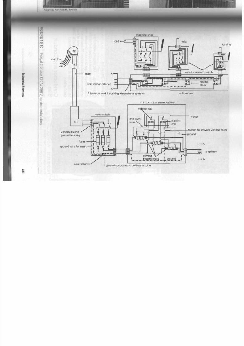
8/19/2019 Applications Electrical
http://slidepdf.com/reader/full/applications-electrical 242/447
3
a.
c
^
c
33
m
—i
a>
o
-<
-g
o '
CO
" O
3 "
a>
0)
CD
r-o
o
<:
NJ
O
CO
<
w
CD
<
o
CD
5 '
en
i-+
9L
QT
o
3
machine shop
drip loop
L B
l o a d — Z
mast
from meter cabinet
2 locknuts and 1 bushing (throughout system)
splitter box
1.2
m
x 1.2 m meter cabinet
main switch
2 locknuts and
'
ground bushing
fuses •
ground wire for mast
neutral block
voltage coil
transformers • neutral
••
meter
ghting
-tease r (to activate voltage coils)
ground
r—A
Z : to splitter
• A
ground conductor to cold-water pipe

8/19/2019 Applications Electrical
http://slidepdf.com/reader/full/applications-electrical 243/447
FIGURE 16.11 A main switchboard room installation
FIGURE 16.12 A dry-type, core and coil
assembly transformer used in a single-ended
unit sub-station
Co nduc tors are often run to these
switchboard systems from a
vault
or
tunnel
built under the unit. Instead
of
using one large, hard-to-handle conduc
tor, several smaller wires or cables
with
a combined am pacity to match the
larger cable are installed. Figure 16.16
shows this type of installation. Note
the
crimp-o,.
solderless lugs
being used to
terminate the cab les.
Grounding.
The
neutral
wire of the
120
V/208
V
system is
grounded
to the
water supply pipe in much the same
as the residential service. This connee
tion gives 120 V between any one of the
live con du cto rs and ground . Check T«
16.1 for sizes of the service ground
conductors.
C onductor and C onduit
Size
Table 5.5, on page 61, lists the current-
carrying capa city of the various
copr.
238
Applications of Electrical Construction
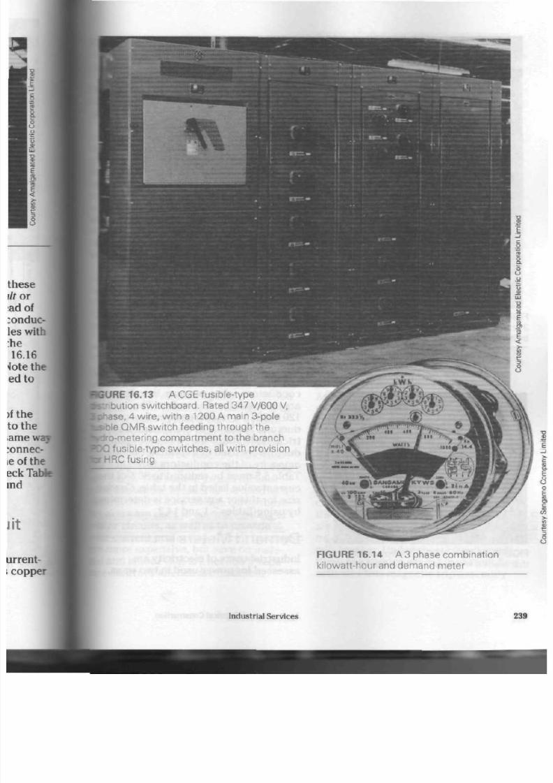
8/19/2019 Applications Electrical
http://slidepdf.com/reader/full/applications-electrical 244/447
SURE 16 .13
A
C G L
fusioie-type
ion switchb oard . Rated 347 V/600 V,
ase, 4 wire, with a 1200 A main 3-pole
ble QMR switch feeding through the
Iro-metering compartment to the branch
fusible-type switches, all with provision
rHRC fusing
FIGURE 1 6.14
A 3 phase com bination
kilowatt-hour and demand m eter
Industrial Services 239
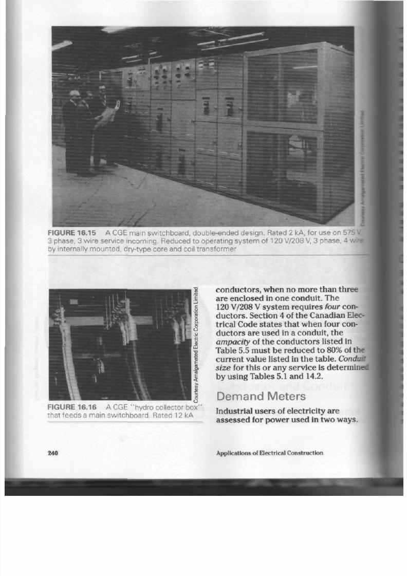
8/19/2019 Applications Electrical
http://slidepdf.com/reader/full/applications-electrical 245/447
FIGURE 16.15 A C GE main switchboard, double-ended design. Rated 2 kA, for use on 575
3 phase, 3 wire service incoming. Reduced to operating s ystem of 120 V/208 V, 3 phase, 4
by internally mounted, dry-type core and coil transformer
FIGURE 16.16
A CGE "hydro collector bo x"
that feeds a main switchboard. Rated 12 kA
conductors, when no more than three
are enclosed in one conduit. The
120
V/208
V system requires four con
duc tors. Section 4 of the Canadian Elec
trical Code states that when four con
duc tors are used in a conduit, the
ampacity of the conductors listed in
Table 5.5 must be reduced to
80%
of the
current value listed in the
table. ConduMj
size
for this or any service is determined
by using Tables
5.1
and 14.2.
Demand Meters
Industrial users of electricity are
assessed for power used in two ways.
240 Applications of Electrical C onstruction

8/19/2019 Applications Electrical
http://slidepdf.com/reader/full/applications-electrical 246/447
be first is the total power consumption,
Iculated
in much the s am e way as for
ential
customers.
le
second way is a charge bas ed on
r
demand factor,
the maximum amoun t
•power
drawn from the utility at any
lien time.
A
special indicator on the me ter
oords
the de ma nd factor by staying at
fc highest reading reached during a
pen
period of time. The meter reader
en takes the reading and tu rns the
fcator back to zero. The dem and fac-
charge
helps ensure that an industry
I
not place unreaso nab le loads on th e
Ity's
supply system for short periods
Ifene. Such load s force t he utility t o
call
large, expensive pieces of equip-
art just for that industry.
Figure 16.14 illustrates a typical 3
hose
com bination m eter which
du de s kilowatt-hours as well as a ther-
••t-type
demand measurement
system,
is me ter is designed to m onitor small
strial loads.
ireuit Breakers
tfh circuit breakers and fuses have
Vantages. This section c overs only the
hrantages
of circuit breaker protection.
One of the greatest adva ntages of th e
ruit breaker
is that it can be a
manu-
y operated
switch. If an ove r-curre nt
•dition
causes the breaker to open
tcircuit,
it can be reset by hand and
1
in opera tion again withou t replacing
• parts.
The built-in switch
mecha-
allows the breaker to b e used as a
itrol
switch for a circuit. Often these
sers
are used to control lighting or
tor circuits, as well as to p rovide
er-current protection . Circuit break ers
: more expensive, but sav e on mate-
l and labour that a re needed if sepa-
te control switches are installed.
l ine connect ion
FIGURE 16.17 O pen view of a circuit
breaker
Figure
16.17
shows a circuit breaker.
A
circuit breaker h as an advantage
when a
short circuit
occu rs. Since a s ho rt
circuit reduces the electrical resistance in
a circuit to a low value, the curr ent flow in
the circuit rises to a high level in
micro
seconds, that is, millionths of a second.
As the alternating cu rren t rises t o a maxi
mum value in its cycle (1/240 s), the cir
cuit breaker sens es this drastic increase
and op ens th e circuit safely.
The circuit is ope ned in two ways. A
heat-sensitive thermal element
(bimetal
strip) rises in temperature and triggers
the circuit break er when excessive cur
rent flows. Also, a prolonged overload
condition will heat u p and op era te th e
thermal elem ent. In the sud den overload
situation, however, a
latch-on,
magnetic
trip assembly quickly operates the cir
cuit breaker. Under short-circuit condi
tions, the sudd en excess in curren t flow
activates this magnetic trip assembly
Industrial Services 241

8/19/2019 Applications Electrical
http://slidepdf.com/reader/full/applications-electrical 247/447
and open s the circuit in m icroseco nds.
Fuses do not have this m agnetic tripping
device.
A
third advantage of circuit breakers
is that th ey are m uch smaller in size
than fused disconnect switches. Figure
16.18 show s a 30 A, 2 pole fused discon
nec t. Figure 16.19 sho ws th e much
smaller 30 A, 2 pole circuit breake r,
which will be mou nted in the distribution
centre shown in the inset. The distribu
tion cen tre is then mo unte d in a wall and
fitted with a finishing cover once the
wall has been covered in. (See Figs. 16.20
and 16.21)
Large industrial load centres are
built with circuit breakers throughout,
and the breaker units are assembled
into sw itch bo ard s. (See Fig. 16.22)
Industrial circuit breakers are mi
in single-pole, double-p ole, and 3 pol
units, with voltage and c urrent
ratings
1
match the circuit conductors. Some
d
the larger units are tripped by com
pressed air to speed up tripping time <
help reduce arc damage to the
breaker
contacts.
Ground Fault Circuit
Interrupters
The ground fault circuit interrupter
(GFI) is a relatively new device
adapto
from the basic circuit breaker.
Provic
what one man ufacturer calls people
protection, it is designed both to pr
dang erous e lectrical shocks and pr
over-current
p rotection. (See Fig. 16J
FIGURE 16.18
switch
A 30 A fused disconnect
FIGURE 16.19
A compact circuit breal
a distribution centre installation
242
Applications of Electrical Construction

8/19/2019 Applications Electrical
http://slidepdf.com/reader/full/applications-electrical 248/447

8/19/2019 Applications Electrical
http://slidepdf.com/reader/full/applications-electrical 249/447
8
1
>-
c
B,
E
o
o
Q
T A B L E 1 6 . 2
0.001 A
.0.005 A
Up
to
0.010
A
0.010A-0.015A
0.015A-0.030A
0.050 A -0.100
A
0.100A-0.200A
Physiological Effects of Elec
trical Currents
Threshold of sensation
Discomfort and pain
Severe pain and shock
Local muscle contraction, possi
ble "freezing-to-the-circuit," or
being thrown back
Breathing becomes difficult, loss
of consciousness possibly result
ing
Possible rapid,
unco-ordinated
contractions of the heart, result
ing in loss of synchronism
between heart and pulse (ventric
ular
fibrillation)
Ventricular
fibrillation
of the heart
FIGURE 16.23 A ground fault circuit
interrupter
low that it will not trip the normal circuit
breaker (o r blow a fuse). But it is high
enough to electrocute, cause serious
harm, or give a painful shock to anyone
who comes in contact with th e faulty
equipment. Portable tools often have
ground faults and cause many electrical
shocks.
Body Resistance
The human body is not a good conduc
tor of electrical current under normal
conditions. The amount of moisture
present (sweat) on the skin and the mus
cle structure of the body help determine
the resistance to current flow at any
given time. Scientific tests have indi
cated body resistance to be between
1000 Q and 4000
Q.
The amount of volt
age present in the circuit will then deter
mine how well the curren t will penetra te
Over 0.200 A Severe burns and muscular con
tractions. Heart is more apt to
stop than fibrillate.
Over 1 A Irreparable damage to body tis
sues
the skin and flow through the
body.
The
higher the voltage present, th e greater
the current flow through the body and
the greater the effect on vital organs.
Table 16.2 indicates how various
amounts of current affect a human
bodd
Time/Current Factor
The age, general health, and amount of
current flow will have an effect on hoic
long a person can sustain a shock
with-
out serious or permanent damage to ti«
body. Figure 16.24 illustrates how mud
time and what current combinations
built into a modern GFI unit for the p
tection of persons using the circuit.
The GFl unit detects leakage curred
as low as 2 mA (0.002
A).
It then opens I
the circuit to protect the operator of tM
equipment.
The average person who receives a I
244
Applications of Electrical Construction
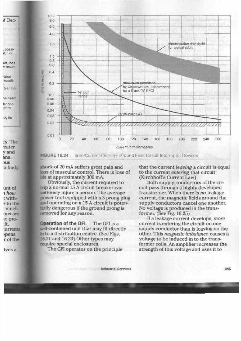
8/19/2019 Applications Electrical
http://slidepdf.com/reader/full/applications-electrical 250/447
-
20 40
60
80 100 120 140 160 180 200 220 240 260
current in milliamperes
RGURE 16.24 T ime/C urrent C hart for Grou nd Faul t C i rcui t Interr upter Devices
shock of 20
mA
suffers great pain an d
loss of m uscu lar c ontro l. There is loss of
Ife at app roxim ately 300 mA.
Obviously, the current required to
trip a norm al 15 A circuit breaker can
seriously injure a person. The average
power tool equipped with a 3 prong plug
and operating on a 15 A circuit is poten
tially dan gero us if the grou nd pron g is
removed for any reason.
Operation of the
GFI.
The GF1 is a
self-contained unit that may fit directly
ID
to a distribution cen tre. (See Figs.
[16.21 and 16.23) Oth er typ es may
require special enclosures.
The
GFI
ope rates on the principle
that the current
leaving
a circuit is equa
to the current entering that circuit
(Kirchhoff's
Current Law).
Both supply con duc tors of the cir
cuit pass through a highly developed
transformer. W hen there is n o leakage
curren t, the m agnetic fields around the
supply conductors cancel one another.
No voltage is produ ced in the tran s
former. (See Fig. 16.25)
If a leakage cu rren t d evelo ps, more
current is entering the circuit on on e
supply con duc tor tha n is leaving on th e
other. This
ma gnetic imbalance
causes a
voltage to b e induced in to the tra ns
former coils. An amplifier incre ases the
strength of this voltage and uses it to
Industrial Service s 24

8/19/2019 Applications Electrical
http://slidepdf.com/reader/full/applications-electrical 251/447
neutral wire
circuit ground
120 V
transformer
0.75
A
leakage c urrent
F I G U R E 1 6 . 2 5 S c h e m a t i c d i a g r a m f o r a g r o u n d f a u l t c i r c u i t i n t e r r u p t e r
trip the circuit breaker. Leakage currents
as low as 2
mA
will trip t he
GFI
breaker.
GFI units are made in a variety of cur
rent ratings to suit m ost circuits. They
are recommended for both home and
industrial protection.
A
special (and
mo re sens itive) unit is being m ade for
ho spita ls. The Canadian Electrical Cod
l ine
terminal
trip latch
surfaces
supervisory
test button
ground fault
calibration resistor
t r ip p in g
solenoid
overload d if ferent ia l
sensing to ro id t ra n sfo rme r
F I G U R E 1 6 . 2 6
I n t e r n a l c i r c u i t r y o f a m o d e r n G F I b r e a k e r u n i t
load lug
overload
calibration
resistor
neutral
toro id
panel
neutral lead
iL
<^g^
246 Applications of Electrical Construction

8/19/2019 Applications Electrical
http://slidepdf.com/reader/full/applications-electrical 252/447
•quires
that swimming, deco rative, or
ler
pools with lighting units be pro-
ted with GFIs. Modern residential
stallations
mu st a lso u se GFIs on all
butdoor rec epta cles, as well as for per-
•onal protection in washroom /bathroom
| e a s .
The internal workings of a
GFI
breaker are not acce ssible to t he
hstaller
or breaker user. They are com
posed
of a sensitive elec tronic circuit
•hich
should not be tampered with or
adju sted in any way. Figure 16.26 illus
tra tes a typical GFI break er s ensing and
monito ring circuit. Figure 16.27 illus
tr at es t his GFI unit in th e form of a sin
gle-pole circuit breaker. Manufacturers
frequently te st their pro duc ts to main
tain qua lity and safety. Users of GFI-pro-
tected circuits should co ntinue to test
the ir GFI un its after ins tallatio n. Figure
16.28 illustrates a typical tes t pro ced ure
recording chart.
•ne terminal screws
•ocation
of labels to indicate
other than class "A "
Jest button
® class "A " ratin g label
©
factory installed permanent
handle t ie
© power wir ing terminals
terminal for " l o a d " neutral
white wire, if available
w h i te "p ig ta i l " mu st be con
nected to the panel neutral
BGURE 16.27 E xternal vie w of single- and double-pole GFI breakers
Industrial Services
247

8/19/2019 Applications Electrical
http://slidepdf.com/reader/full/applications-electrical 253/447
TEST REMINDER
For maximum protection against electrical
shock hazard, test your ground fault circuit inter
rupter at least once a m onth.
TEST PROCEDURE
1. Push yel low TEST button. The red RESET
button will pop out exposing the word
TRIP.
Pow er is now o ff at all outlets protected by the
INTERRUPTER,
indicating that the device is
functioning properly.
2. If
TRIP
does not appear when testing, do not
use any outlets on this circuit. Protection is
lost. Call a qualified electrician.
3. To restore
power,
push
RESET
button. Enter
data on record below.
Marth
19
19
19
19
19
19
19
19
19
19
19
19
19
19
19
Jan
Feb
M r
%
May Jm
Jul Aug Sep Oct
Nov Dec
FIGU R E 16 .28 Typical GFI Tes t P roc edure
R ec ord ing Char t
F o r R e v
i
e w
1. What are three advantages of the
polyph ase, or 3 phase, voltage sys
tem in industrial or m anufacturing
buildings?
2.
How is a 3 pha se service
meteredl
3. W hat is the size of a grou nding
conductor for a 200
A
service'.' a
400
A
service? a 600
A
service?
4.
List the boxes or enclosures used
in a 3 pha se service.
5.
How is a 3 phase disconne ct
switch different from a single-
phase disconnect?
6. How is the gro unding of a 3 phasq
550
V
service different from
that
a single-phase service?
7.
Explain why current transformers
are used.
8. What advantage has the 4 wire,
120
V/208
V
service over the 3
wire, 550
V
or 440
V
installation?
9. When installing a 3 ph ase , 4 wire
service , how is the am pacity
of
conduc tors determined?
10.
What is a
demand
meter? Why
how is it used?
11.
List thre e m ain advan tages a cir
cuit break er h as over a fuse.
12.
List two types of circuit
protec
provided by circuit breakers.
13.
In which two ways d oe s a circuit
break er trip a circuit when under]
short-circuit conditions?
14.
Why is it im po rtant to trip a ci
breaker in microsecon ds w hen a
short circuit occurs?
15. What method is used to trip large
industrial circuit breakers? Whya
16.
What is aground fault?
17. List thre e ways in which ground
faults often occur.
18.
Why is a standard circuit breaker]
(or fuse) som etimes u seless when
a ground fault occurs in a circuit?
19.
What is the low est cur ren t level
which a
GFI
in th e circuit can o
ate?
20.
Explain in your own w ords how
GFI unit o pe ra tes .
248 App lications of Electrical Con struction
8/19/2019 Applications Electrical
http://slidepdf.com/reader/full/applications-electrical 254/447
Fuses
W
hen an electrical current passes
through a conductor, som e heat is
generated. The more current that passes
through a conductor, the m ore heat is
generated within the conductor.
The amount of heat pro duced is pro
portional to the squ are of the c urre nt.
That is, if the am oun t of curren t in a con
du cto r is dou bled, the h eat will be four
times as great. If th e am oun t of cur ren t
in the sam e con duc tor is tripled, the
heat will be nine times as great.
There are several othe r factors th at
affect the amount of heat produced in
any given cond ucto r. One is the ty pe of
metal used in the conductor. Copper is a
better conductor than aluminum, and so
will ca rry m ore cu rren t. Because it can
carry more current, a copp er condu ctor
of a given size and cu rrent load will gen
erate less heat than an aluminum con
ductor under the same conditions.
The physical
size—the gauge
number—of the conductor also helps
determine the current-carrying capacity
of the cond ucto r and, therefore, th e
amount of heat that will be generated
under certain loa ds. Small co ndu ctors
do not carry as much c urrent as large
cond uctors. Therefore, a small cond uc
tor trying to carry too large a cu rrent
load will generate more heat than a
conductor of the right size would.
A third factor is the air surrounding a
cond uctor. Air space h as a great deal to
do with the co ndu ctor's ability to cool or
give off its heat. The tem pe rat ur e of th e
air surroun ding th e condu ctor is called
th e ambient
temperature.
If con ductors
are crowded into a conduit or box wh ere
there is little air circulation, cooling will
be difficult, and a higher ambient tem
per atur e will result. This ambient tem
per atur e will therefore raise the tem per
ature of the cond ucto rs. Areas such as
boiler rooms and foundries often have
problems with conductors because of
high ambient temperatures.
A cond uctor 's insulation can also
affect a co nd uc to r's ability to give off
heat. Some modern plastic insulations
tend to retain the heat in the cond uctor
in the sa me way that insu lation in a
building's walls holds in heat. Therefore,
th e current ratings for these cond uctors
must not be exceeded. If they are, suffi
cient heat will be generated and retained
to melt or damage the insulation. Tables
5.5 and 5.6 list the curren t-carrying
capacities of copp er and aluminum con
du cto rs. Heat rises t o a significant level
in thes e cond uctors when about
80%
of
the listed current is passed through the
conductor.
Fuses
249

8/19/2019 Applications Electrical
http://slidepdf.com/reader/full/applications-electrical 255/447
Note: Some electrical equipm ent,
such as special circuit breakers and
pressure-typ e switches designed for
use with HRC-L fuses, is rated for 100%
capacity.
Damage from Overheating
Overheating of condu ctors results in
several problem s. One is caused when
a conductor reaches a temperature
beyond its normal operating range.
There is a softening, called annealing, of
the con ducto r which rem oves any resili
ence (spring-like action) at the terminal
and may loosen th e connec tion. (This is
much like the cold flow of m etal exp eri
enced with aluminum conductors.)
An increase in tem per ature also
brings about a more rapid rate of
oxidation on a cond uctor. Copper is a
good conduc tor, but co pper oxide is not.
In fact, copper oxide tends to weaken
the electrical security of a terminal con
nection. Aluminum oxide causes an even
grea ter prob lem. Very close to be ing an
insulator, it will cause further heating at
the term inals. The oxide establishe s an
electrical resistance, which results in a
loss of voltage at the terminal. Often,
enough heat is generated to completely
destroy the terminal connection.
Overheating also causes
insulation
to
dry out and becom e hard and brittle. In
fact, movement of the conductor will
likely cause the insulation to crack and
fall off. The exposed conductors may
well sta rt a fire if they to uc h e ach oth er
or a groun ded box. Although it usually
takes m any months of circuit use to dry
out insulation, the problem can easily be
overlooked: conductors are seldom
checked after installation.
If th er e is an overload or short-cir
cuit current, conductors can heat up
until they actually glow red. When th is
overheating o ccurs , the insulation can
melt, causing arcing between conduc- |
tors or between the cond uctors and
ground. A fire can be ignited within the
cond uit, b ox, or b uilding w all. Even if I
actual damage from the fire is small,
tl
burning insulation gives off an offensn*
odour that will persist for a long time-
Obviously, the overh eating of con
du ctor s can have serious effects. The
Canadian Electrical Code recognizes I
by requiring over-current protection ti
be provid ed. One effective way to p r o -
tect a circuit is with a
fuse.
Weakest Thermal Link
A fuse
is a simple, current-sensitive
dev ice designed to limit curren t flow
pro tec t the co ndu ctors of a circuit.
P
tecting the co ndu ctors will prevent sd
ous dam age to equipmen t from overta(
and fire.
A fuse con tains a strip of
current-
sensitive metal that has been calibrated
to melt and restrict the amount of over
load and short-circuit currents for cop
per or aluminum circuit co ndu ctors,
metal used in a fuse can be zinc, cop
silver, or an alloy, depen ding on the
type and use. Industrial fuses have
co]
per or silver links to which a small
am oun t of tin or tin alloy has been
add ed to redu ce their melting tern
ture.
This principle is known as the
effect. Tin or tin alloy is deposited on
th e link, close to a restrictive segmenL
thus reduces the overload melting
tea
perature at that section of the link. Tta^
normal copper or silver used for the
links has a melting tem pe ratu re of
approximately 1000°C which will open
und er short-circuit cond itions, but not
at the lower, safer tem per ature range
required for protection from overload*
250
Applications of Electrical Construction
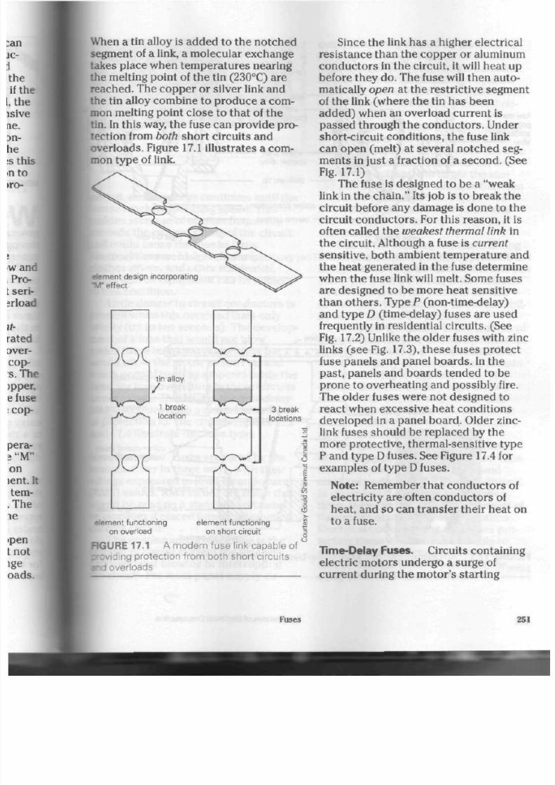
8/19/2019 Applications Electrical
http://slidepdf.com/reader/full/applications-electrical 256/447
When
a tin alloy is ad ded to the notc hed
segment of a link, a mo lecular excha nge
takes place when tem pera tures nearing
the melting point of the tin (230°C) are
reached. The copper or silver link and
the tin alloy combine to pro duc e a com
mon melting point close to tha t of th e
tin. In this way, the fuse can provid e pro
tection from
both
short circuits and
overloa ds. Figure 17.1 illustrates a com
mon type of link.
element des ign incorporating
"W
effect
tin alloy
1 break
location
3 break
locations
E
x :
( / >
S
3
o
element functioning
on overload
element functioning
on short circuit
FIGURE 17.1 A mo de rn fuse l ink capable of
p-cviding protect ion f rom both short c i rcui ts
• n d ov er loads
Since the link has a higher electrical
resistance than the copper or aluminum
co nd uc tor s in the circuit, it will heat up
before they d o. The fuse will then auto
matically
open
at the restrictive segment
of the link (wh ere th e tin has been
added) when an overload current is
passed through th e conduc tors. Under
short-circuit conditions, the fuse link
can open (melt) at several notched seg
m en ts in just a fraction of a sec ond . (See
Fig.
17.1)
The fuse is designed to be a "weak
link in th e chain ." Its job is to brea k th e
circuit before any damage is done to the
circuit conductors. For this reason, it is
often called the w eakest thermal link in
the circuit. Although a fuse is current
sensitive, both ambient temperature and
the heat gene rated in the fuse determ ine
when the fuse link will melt. Some fuses
are designed to be m ore heat sensitive
than others . Type P (non-time-delay)
and type D (time-delay) fuses are used
frequently in residential circu its. (See
Fig. 17.2) Unlike the older fuses with zinc
links (se e Fig. 17.3), th es e fuses pro tec t
fuse panels and panel boards. In the
past, panels and boards tended to be
prone to overheating and possibly fire.
The older fuses were not designed to
react when excessive heat cond itions
deve loped in a panel b oard . Older zinc-
link fuses should be replaced by the
more protective, thermal-sensitive type
P and type
D
fuses. S ee Figure
17.4
for
examples of type D fuses.
Note: Remember that conductors of
electricity are often conductors of
heat, and so can transfer their heat on
to a fuse.
Time-Delay Fuses . Circuits containing
electric motors undergo a surge of
current during the motor's starting
Fuses
25
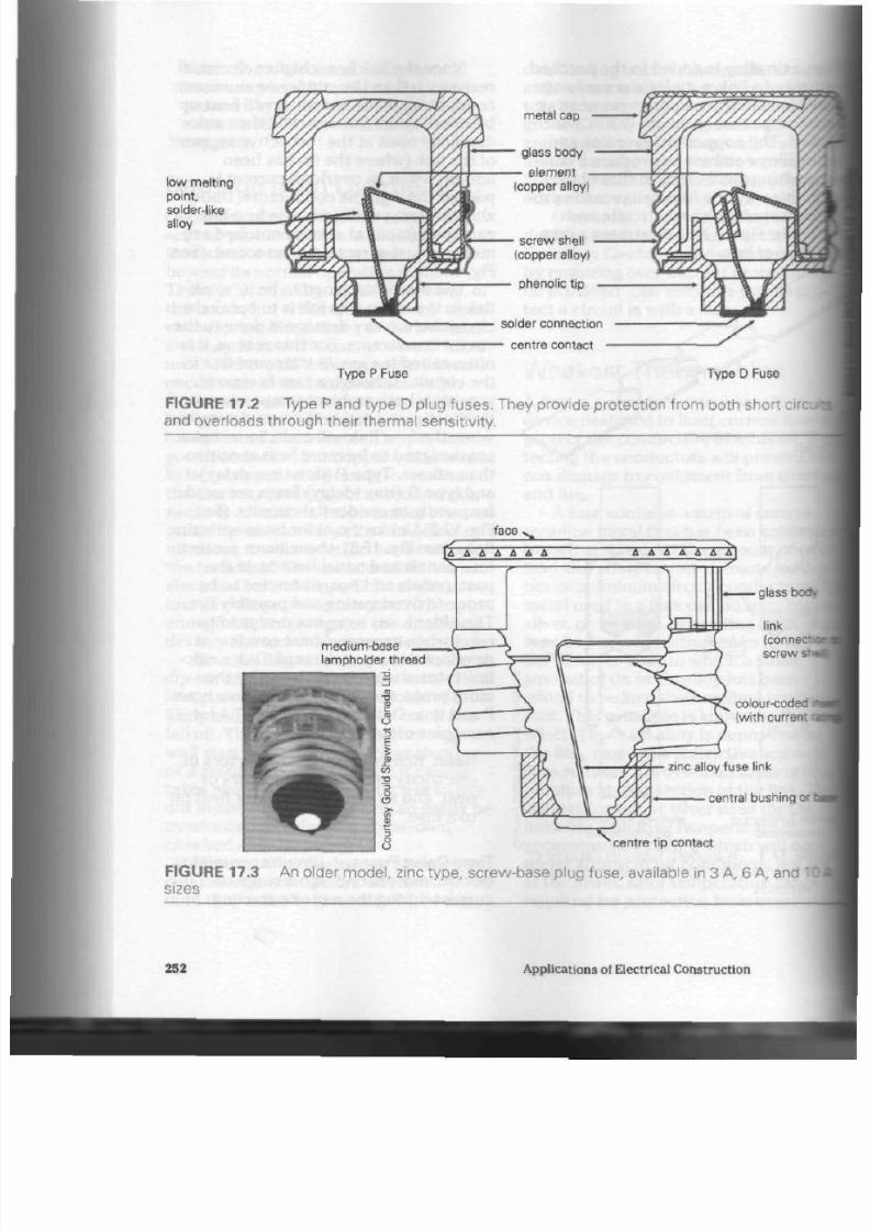
8/19/2019 Applications Electrical
http://slidepdf.com/reader/full/applications-electrical 257/447
low melt ing
point,
solder-like
alloy
Type P Fuse
metal cap
glass body
element
(copper alloy)
screw shell
(copper alloy)
phenolic tip
solder connection
• centre contact
Type D Fuse
FIGURE 17.2 Type
P
and type
D
plug fuses. They provide protection from both short
circti
and overloads throug h the ir thermal sensitivity.
face
glass body
link
(conne
screw
she
colour-codec
ne
(with current
i
r
— zinc alloy fus e link
y
• central bushing
or
centre tip contact
FIGURE 17.3 A n older mod el, zinc type , screw-base plug fuse , available in 3 A, 6 A, and
sizes
252 Applications of Electrical Construction

8/19/2019 Applications Electrical
http://slidepdf.com/reader/full/applications-electrical 258/447
SURE 17.4 Metal-capped type D plug
»es
period, and the surge co ntinues until th e
motor reaches operating speed. This
sudden increase of current frequently
exceeds th e curren t rating of th e circuit
and could ca use th e fuse to blow.
Air conditioners, fridges, freezers,
clothes driers, and other residential,
motor-driven equipment ca n be subject
to this condition.
Little danger to circuit conductors is
present when this overload lasts only
briefly (up to ten seconds). The develop
ment of a fuse that would not blow
under these temporary overloads but
would allow the m otor to sta rt u p and
reach normal running amperes made the
need for fuse oversizing in th es e c ircuits
unnece ssary. This fuse is the time-delay
fuse w hich provides a m uch be tter level
of protection for the circuit. Figures
17.2
and 17.4 illustrate this fuse typ e.
Fuse Ratings. Fuses are rated by th e
manufacturer in thr ee ways, with their
ratings expres sed in Root Mean Squ are
(RMS) va lue s.
RMS
values are those that
would be read on a stand ard voltme ter
or ammeter if placed into an alternating
current circuit.
The continuous current rating is the
amount of circuit current the fuse will
carry without blowing or interrupting
the circuit. For most pa nel-supply cir
cuits, this rating should b e matched to
the current rating of the circuit conduc
tors .
It mu st also com ply with Canadian
Electrical Code maximums for specific
loads, such as mo tors and transformers,
wh ere cur ren ts ar e likely to exceed cir
cuit ampacity.
Maximum AC rated voltage
indicates
to th e installer the typ e of circuit and
voltage conditions unde r which the fuse
can safely operate. In most cases, the
higher the voltage, the larger th e size
(length) of the fuse or distance between
the fuse's contact points. Figure 17.8
illustrates differences in physical size
between fuses of various voltage and
current ratings.
Due to the serious, sustained arcing
associated with
DC
circuits, special
designs have been developed for this cir
cuit t yp e. If the
DC
rating is not marked
on the fuse label, th e installer sho uld
contact the manufacturer about suitabil
ity of th e fuse on
DC
circuits.
Interrupting capacity is the am oun t of
current that the fuse can safely interrupt
in the circuit under short-circuit condi
t ions. The bo dy of the fuse m ust rem ain
intact, allowing for replacem ent. The
current flow can be very high when a
sho rt circuit occ urs, and so the inter
rupting capacity of the fuse used must
ma tch or exceed th e short-circuit cur
rent from the circuit's source.
Depending on their size, transform
ers supplying residential areas are capa
ble of delivering up to te n thou sand
amperes under short-circuit conditions.
In commercial and industrial applica
tions, they can deliver up to hundreds of
thou san ds of am peres. The Canadian
Electrical Code require s that fuses pro
tecting the se c ircuits must b e able to
safely open the circuits without fuse rup
ture or damage to their panels or the
equipment that contains them.
Fuses 253

8/19/2019 Applications Electrical
http://slidepdf.com/reader/full/applications-electrical 259/447
S crew-Base, or P lug, Fuses
The m ost com mon type of fuse used in
residential buildings is the screw-base,
usually called the plug fuse. (See Figs.
17.2 and 17.3 on pag e 252.) Plug fuses
are used for all lighting and receptacle
circuits operating at a maximum voltage
of 125 V. Standard plug fuses are m ade in
current ratings of 3 A, 6 A, an d 10 A for
th e zinc-link type s and 15 A, 20 A, 25 A,
and 30 A for th e P and D types.
Time-delay plug fuses of less than
15 A
are available in fractional am pe re
rating s. Figure 17.2 show s a time-delay
fuse in th e plug-type configuration. (The
section on dual-element fuses in this
cha pter discu sses the cartridge type.)
Plug fuses a re all abo ut th e sam e
phy sical size. Older zinc-link typ es hav e
colour-coded inse rts. The ins erts are vis
ible through the transp aren t top s of the
fuses to aid in ea sy recogn ition of cur
rent ratings, even from a distanc e. In
the pa st, the current rating was often
stamped on the contact point at the fuse
base. Some manufacturers found that
stamping the base could distort the con
tac t point and lead to overheating in the
panel .
In
an effort t o preven t thes e p rob
lems,
they now take more care whe n
marking the se con tact p oints. Many
modern type P fuses still use colour-
code d inserts under their t ransparen t
faces,
though; mo dern type D fuses ha
colour-coded metal caps over their fa
and top s. Blue represen ts
15
A;
orangi
20 A; red, 25 A; and green , 30 A.
For a period of time, a
colour-cc
ba se was installed on th e fuse to mate
up with a fuse rejection system that
could be installed in a pan el's fuse
of
ing. Th ese sy stem s were designed to
pre ve nt th e placing of a fuse having to
large a current rating into the circ uit
(See Fig. 17.5) W hen this situation
occurred, the older zinc-link fuse wc
allow he at t o build up far bey ond sal
levels and not op en. Modern type P;
type
D
fuses, which have overload-sen
ing features built-in, will ope n the cird
when t he re is an overload he ating co«
tion. However, desp ite this additional
protect ion, their amp acity should not
exceed circuit conductor capacity.
Note: Some manufacturers of
paneM
built rejection features into their
panels and did not require the
coloured inserts to be installed at
a
later time.
20 A fuse
(central bushing
will not fit into
15 A rejection
washer)
contact
incomplete
rejector
washer
15 A fuse
fully installed
contact
complete
F I G U R E 1 7 . 5 A f u s e r e j e c t o r r i n g a p p l i c a t i o n u s i n g t y p e P o r t y p e D p l u g f u s e s
254
A ppl ications of E lectr ical C onstruct ion
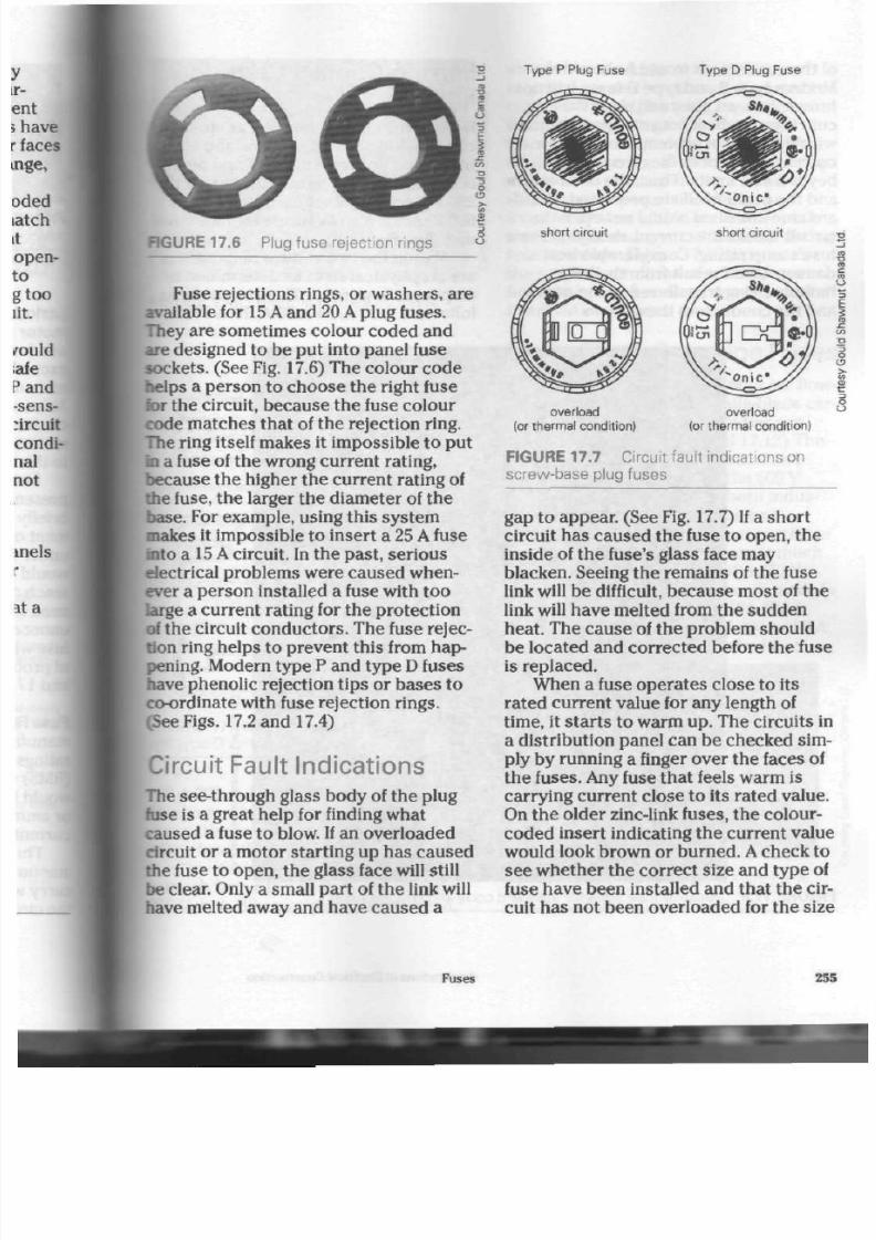
8/19/2019 Applications Electrical
http://slidepdf.com/reader/full/applications-electrical 260/447
RGURE 17.6 P lug fuse reject ion r ings
Fuse rejections rings, or washers, are
available for 15 A and 20 A plug fuses.
They are sometimes colour co ded and
are designed to be pu t into panel fuse
sock ets. (See Fig. 17.6) The colour c od e
helps a person to choose the right fuse
lor
the circuit, bec ause the fuse colour
code matches that of the rejection ring.
The ring itself makes it impossible to put
in a fuse of the wrong cu rrent rating,
because the higher the current rating
of
the fuse, th e larger the d iam eter of th e
base. For exam ple, using this sy stem
makes it impossible to insert a 25 A fuse
into a
15 A
circuit. In th e past, seri ou s
electrical problems w ere caused when
ever a perso n installed a fuse with too
large a current rating for the prote ction
of the circuit con du cto rs. Th e fuse rejec
tion ring helps to prev ent th is from hap
pening. Modern typ e P and typ e D fuses
have phenolic rejection tips or bases to
co-ordinate
with fuse rejection rings.
(See Figs. 17.2 and 17.4)
Circuit Fault Indications
The see-through glass body of th e plug
fuse is a great help for finding what
caused a fuse to blow. If an overloaded
circuit or a motor sta rting up ha s cause d
the fuse to open , the g lass face will still
be clear. Only a small part of the link will
have melted away and have cau sed a
Type P Plug Fuse Type D Plug Fuse
short circuit short circuit
overload
(or thermal condition)
overload
(or thermal condition)
FIG URE 17.7 C i rcui t faul t indicat ions on
s c rew - bas e p lug f us es
gap to appe ar. (See Fig. 17.7) If a sh or t
circuit has cau sed th e fuse to open, t he
inside of the fuse's glass face may
blacken. Seeing th e rem ains of th e fuse
link will be difficult, be cause m ost of the
link
will hav e melted from th e su dde n
heat. The cause of the problem should
be located and corrected before the fuse
is replaced.
When a fuse o per ates close to its
rated curre nt value for any length of
time, it sta rts to warm up. Th e circuits in
a distribution panel can be checked sim
ply by runn ing a finger over th e faces of
th e fuses. Any fuse th at feels warm is
carrying current close to its rated value.
On the older zinc-link fuses, the colour-
code d insert indicating the current value
would look brown or bu rned . A check to
see w heth er the correct size and typ e of
fuse have been installed and that the cir
cuit has not been overloaded for the size
Fuses
255

8/19/2019 Applications Electrical
http://slidepdf.com/reader/full/applications-electrical 261/447
of the co ndu ctors w ould be in order.
Modern type P and typ e
D
fuses will not
brow n. Instead, the y will op en the cir
cuit: they are heat sensitive and respond
with this type of protection whe n t he
current and heat in the circuit go
beyond safe limits. Thus, the conductors
and the panel itself are protected. Stand
ard zinc-link fuses would not ope n th e
circuit unless the current exceeded the
fuse's amp rating. Considerable heat
damage could result from the heat
buildup being transferred to the panel
and the conductors themselves.
Ferrule-Contact Cartridge
Fuses
Residential equipmen t su ch as stoves,
clothes driers, water heaters, and
elee
trie
heaters operate at 240
V
and
oftea
need a different type of fuse, usually ta
250
V ferrule-contact
cartridge fuse.
A
600
V
unit is also available for
industry
use. (See
Fig. 17.9)
Within the two voltage ran ges
thea
are six physical sizes as determined
b
am pere rating group. The group s are a
follows: 1 A-30
A,
35 A-60
A,
70 A-100
A
o
FIGURE 17.8 Relative fuse sizes for standard code and HRCl-R fuses
256
Applications of Electrical Construction
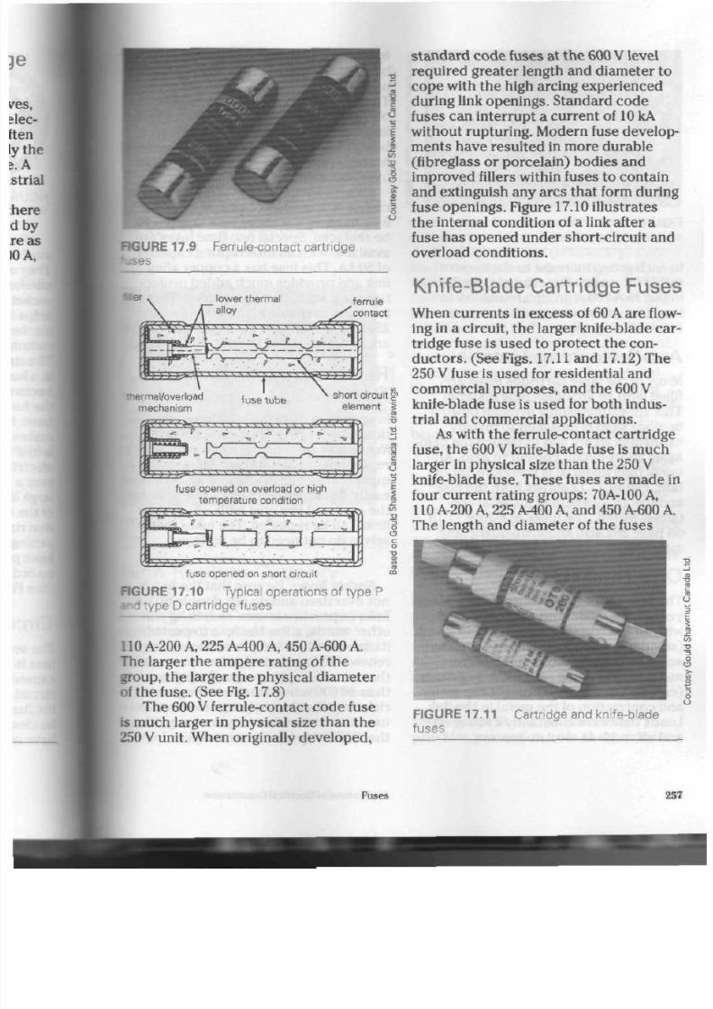
8/19/2019 Applications Electrical
http://slidepdf.com/reader/full/applications-electrical 262/447
RGURE
17.9
Ferrule-contact cart r idge
lower thermal
alloy
y
ferrule
contact
-/~V
•T>.
-lal/overload
mechanism
s v ,
\
s
\ vs
s
s
s
•, s V ^ - ^ m
fuse tube
short circuit g
element i
fuse opened on overload or high
temperature condition
11
t
;• •. -. -. '. '•
'. ',
'. s \ •. ', \ ^ ^
fuse opened on short circuit
FIGURE 17.10 Typical opera t ions of type P
ype D cart r idge fuses
110
A-200
A,
225
A-400 A,
450 A-600 A.
The larger the ampere rating of the
group, the larger the physical diameter
of
the fuse. (See Fig. 17.8)
The 600 V ferrule-contact code fuse
is much larger in physical size than the
250 V
unit. When originally d eve loped ,
standard code fuses at the 600 V level
required greater length and diameter to
cop e with th e high arcing e xperienced
during link openings. Standard code
fuses can interrupt a current of 10 kA
without rupturing. Modern fuse develop
me nts have resulted in mo re durab le
(fibreglass or porcelain) bodies and
improv ed fillers within fuses t o c ontain
and extinguish any arcs that form during
fuse openings. Figure 17.10 illustrates
the internal condition of a link after a
fuse has opened under short-circuit and
overload conditions.
Knife-Blade Cartridge Fuses
When cur ren ts in exc ess of 60 A are flow
ing in a circuit, t he larger
knife-blade
car
tridge fuse is used to protect the con
ductors. (See Figs. 17.11 and 17.12) The
250 V fuse is used for residential and
commercial purp oses, and the 600
V
knife-blade fuse is used for bo th in dus
trial and commercial applications.
As with the ferrule-contact cartri dge
fuse, the 600 V knife-blade fuse is muc h
larger in physical size th an the 250 V
knife-blade fuse. These fuses are made in
four current rating groups:
70A-100
A,
110 A-200 A, 225 A-400 A, and 450 A-600
The length and diam eter of the fuses
F I G U R E 1 7 . 1 1
f us es
Cart r idge and kni fe-blade
Fuses
25
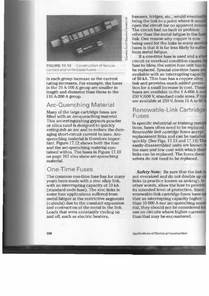
8/19/2019 Applications Electrical
http://slidepdf.com/reader/full/applications-electrical 263/447
FIGURE 17.12 C onstruction of ferrule-
contact and knife-blade fuses
in each group increase as the current
rating increa ses. For example, the fuses
in the 70 A-100 A group a re smaller in
length and diam eter than tho se in the
110A-200Agroup.
Arc-Quenching Mater ial
Many of the large cartrid ge fuses are
filled with an arc-quenching material.
This arc-extinguishing gypsum powd er
or silica sand is designed to quickly
extinguish an arc and to reduce the dam
aging short-circuit cu rrent to zero . Arc-
quenching material is therefore impor
tant. Figure
17.12
shows both the fuse
and the arc-quenching material con
tained within. The fuses in Figure 17.19
on page 262 also show arc-quench ing
material.
One-Time Fuses
The comm on one-time fuse h as for many
yea rs be en ma de with a zinc alloy link,
with an interrupting capacity of
10
kA
(stand ard cod e fuse). The zinc links in
some fuse applications suffered from
metal fatigue at the restrictive segments
(cutouts) due to the constant expansion
and con traction of the m etal in the link.
Loads that were constantly cycling on
and off, such as electric heaters,
freezers, fridges, etc., would
event
bring the link to a point w here it w
open the circuit for no apparen t re
The circuit had no fault o r problem
other than the metal fatigue in the
link. One rea son w hy co pp er is now
being used for the links in many m
fuses is that it is far less likely to
s
from metal fatigue.
If a one-tim e fuse is used and a
circuit or overload condition cause
fuse to blow, the entire fuse unit ha
be replaced. Special
one-time
fuses
available with an interru pting capa
of 50 kA. This fuse has a c op pe r al
link and provides much added prot
tion for a small incre ase in cost.
Th
fuses are available in th e 1 A-600 A
250
V/600 V, sta nd ard cod e sizes.
are available at 250
V,
from
15 A
to
Renewable-Link Cartrid
Fuses
In
specific industrial or training in
tions, fuses often need to be repla
Renewable link cartridge fuses acc
replace me nt links and can be insta
quickly. (See F igs. 17.13 and 17.14)
easily disassem bled units are know
th e ease and low cost with which t
links can be replac ed. The fuses th
selves do not need to be replaced .
Safety Note: Be sur e that th e lin
not oversized and do not double u
links (a practic e known as spiking)
oth er w ords, allow the fuse to prov
its intended level of protection. Sin
renewable-link cartrid ge fuses ha v
ther an interrupting capacity highe
tha n 10 000 A nor arc-quench ing m
rial, they should not be considered
use on circuits whe re higher cu rre
than that may be encountered.
258
Applications of Electrical Co nstruction

8/19/2019 Applications Electrical
http://slidepdf.com/reader/full/applications-electrical 264/447
=1GURE
17.13
-se
jyt .
FIGURE 17.14 A renewa ble-link knife-blade
High-Rupture Capacity
Fuses
Section 14 of the C anadian Electrical
Code states that standard code car
tridge fuses m ust no t be used in circuits
that have a curren t in exce ss of 600
A
and a voltage in ex cess of 600 V.
Another considera tion is that fuses
must have ratings app ropria te for th e
handling of anticip ated short-circu it
currents. High-rupture capacity (HRC)
fuses provide good protection from both
overloads and sho rt circuits; as noted
earlier in this chapter, mo dern distribu
tion systems often deliver short-circuit
currents far above the ability of stand
ard co de fuses to inter rup t safely.
HRC fuses can be used with m oto rs
when a time-delay feature is required, as
well as with other high current-consum
ing equipm ent, for exam ple, lighting
loads, transform ers, e tc. They provide
rapid protection from short circuits and
can also provide needed time delays
during the m oderate (tem porary) over
loads experienced when motors or
transformers are first turned on. HRC
fuses also do not deteriorate. Most have
moisture-proof fibreglass or ceramic bar
rels, filled with high -quality silica san d
for arc-quenching. Under heavy current,
short-circuit conditions, the silica sand
quickly tur ns into a glass-like m aterial,
blocking any ch an ce of an arc forming
between fuse ends. The copper links and
silver- or tin-plated, copper contact
blades add to th e
HRC
fuse's overall
quality. (See Fig. 17.15)
HRC fuses are designed to inter rup t
large short-circuit c urren ts without rup
turing and to pro tect ca bles and equip
men t w ell. They a re available in two
basic ty pes. The Form I and Form II fuse
are known as HRC-I and HRC-II, resp ec
tively. Electrical and physical differences
exist between the two types .
HRCI (Form I). The se fuses provide
protection from bo th overload s and
sho rt circuits. They hav e a high
interru pting capa city (200 kA) and are
made in a variety of types and classes
for use in protecting cables and
equipment.
HRCII (Form II). Th is kind of fuse
provides protection from sh ort circuits
Fuses 25

8/19/2019 Applications Electrical
http://slidepdf.com/reader/full/applications-electrical 265/447
FIGURE 17.15 Typical HRCII-C fuses
only and m ust be used in conjunction
with som e other type of overload device
(most often an overload relay). Although
it ha s
a
200
kA
interrupting capacity,
it
mu st never be used to replace an HRCI
fuse. An
HRCI
fuse can, however,
be
used
to replace an HRCII fuse, sinc e it pro
vides both types
of
protection.
The common types of
HRC
fuses are
as follows.
HRCII-C This HRCII fuse is of British ori
gin, with
a
bolt-in design.
It is
availa
ble with electrical ra tings of
600 V
and 2 A-G00 A. It is generally used as
a backup, short circuit device for
motor circuits,
and
often u sed along
with combination motor starters
or
other o verload dev ices. (See Fig. 17.15)
Class H These fuses, of th e HRCI type,
had the same basic dimensions
as
standard code cartridge fuses of the
same current and voltage ratings.
The 1 A-60 A and 70 A-600 A types
had rejection tabs or notche s in thd
contact areas
to
prevent the insta ll
tion of 10 kA standard code fuses •
panels or equipment. They w ere pn
duced in bo th th e 250 V and 600 V
versions with current ratings from
1 A-600 A. Fast-acting and time-del^
units were also developed. Howewi
Class H fuses are now considered
obsolete and should
be
replaced
t l
HRCI-R fuses.
HRCI-J Th ese fuses are designed for us
in mod ern equipm ent and have sup
rior curr en t limiting ability. Their
specific compact dimensions pre- j
vent them from being intercha nge *
with any othe r type
of
fuse. T hese
fuses a re ma de in
the 1
A-60
A
fer
rule-contact type and the 70 A-600^
bolt-in/blade ty pe, all with voltage
ratings of 600 V. T he fast-acting typ
is used
for
the protection
of
feed-r-
circuits and for providing a needed
short-circuit protection for circuB
breakers. (See Fig. 17.16) HRCI-J
time-delay typ es a re available
for
both the NEMA and the sm aller 1EC
types
of
motor/control contactor;
They can also be used to protect
transformers.
HRCI-R T he HRCI-R fuse ha s overall
dimensions similar to those of the |
standard fuses covered earlier inl
chapter.
A
replacement
for
th e
CI
fuse, it has a special rejection feataj
—a groove on th e ferrule (1 A-60
or a "U" shap ed notch on the kni
blade contact
of
th e larger (70
A-l
type. The rejection feature
is
four
on one end of the fuse only.
The fuses are produced in
25C
and 600 V sizes with curr ent ratir
from 1 A-600 A, including fractional
260
Applications
of
Electrical Construction
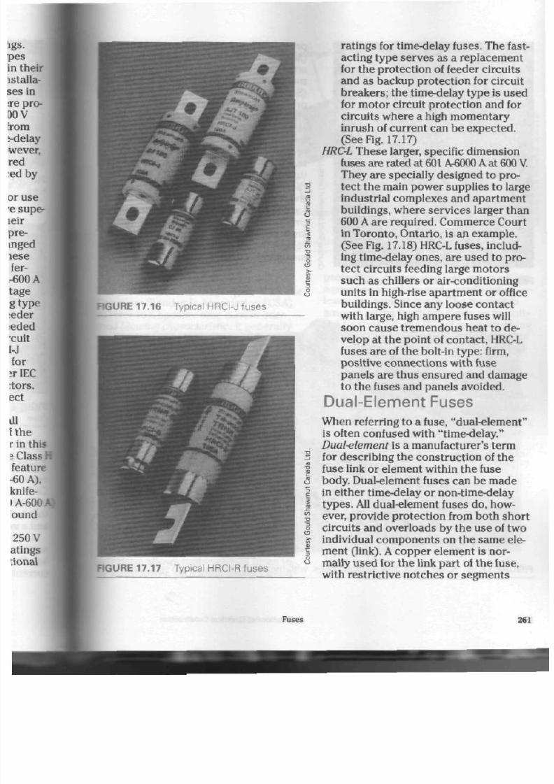
8/19/2019 Applications Electrical
http://slidepdf.com/reader/full/applications-electrical 266/447
FIGURE 17.16 Typical HRCI-J fuses
E
5
.c
to
2
O
o
>•
o
a
FIGURE 17.17 Typical HRCI-R fuses
ratings for time-delay fuses. The fast
act ing type serve s as a replacem ent
for the protection of feeder circuits
and as backup protection for circuit
break ers; the time-delay type is used
for motor circuit protection and for
circuits where a high mo men tary
inrush of current can be expected.
(See
Fig.
17.17)
HRC-L
These larger, specific dimension
fuses a re rated at
601
A-6000
A
at
600
They are specially designed t o pro
tect th e main pow er supplies to large
industrial complexes and apartm ent
buildings, wh ere serv ices larger than
600 A are required. Comm erce Cour
in To ronto, Ontario, is an exam ple.
(See Fig.
17.18)
HRC-L fuses, includ
ing time-delay on es, are used to p ro
tect circuits feeding large motors
such as chillers or air-conditioning
units in high-rise apartment or office
buildings. Since any loose con tact
with large, high ampere fuses will
soon cause tremendous heat to de
velo p at th e poin t of con tact, HRC-L
fuses are of the bolt-in type: firm,
positive connections with fuse
panels are thu s ensured and damage
to the fuses and panels avoided.
Dual-Element Fuses
Wh en referring to a fuse, "dual-elem ent"
is often confused with "time-delay."
Dual-element
is a ma nufacturer 's term
for describin g the con struction of the
fuse link or elem ent within th e fuse
body. Dual-element fuses can be made
in either time-delay or non-time-delay
types .
All dual-eleme nt fuses d o, how
ever, provide protec tion from both sho r
circuits and o verload s by the use of two
individual com pon ents on the sam e ele
ment (link). A cop per element is nor
mally us ed for th e link pa rt of th e fuse,
with restr ict ive notch es or segm ents
Fuses
26

8/19/2019 Applications Electrical
http://slidepdf.com/reader/full/applications-electrical 267/447
e
i
2
providing pro tection from sh ort
circuM
(See Fig. 17.19) One end of the
element
attac he d to th e fuse c on tact by a low-
thermal alloy and a plunger
mechanisJ
(See Fig. 17.20) The m echanism provided
protection from overload by sensing aa
above normal temperature on the fuse
element, melting the low-thermal
allojt I
and allowing a spring within th e mecha-
nism to open the circuit. The time
required for this reaction se rves as the j
time-delay feature on type D fuses. The
thermal sensitivity of such fuses coven
th e requ irem ents of a residential code
ca rtridg e fuse. Dual-element fuses are
prod uce d in both ferrule-contact and
knife-blade contact types, in current
ranges from 1A - 600 A and in both 250
and 600
V
configurations.
FIGURE 17.18 Typical HRC-L fuses
arc-quenching m ater ia l
thermal cutout
lock-in device
arc-quenching mater ia l
FIGURE 17.19 O lder style, dual-element fuses, with therma l cutouts in centre sections
262
Applicat ions of Electr ical Construct ion
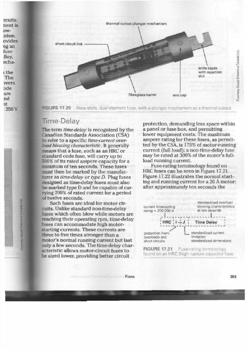
8/19/2019 Applications Electrical
http://slidepdf.com/reader/full/applications-electrical 268/447
t her m al c u t out p lunger m ec han is m
short circuit l ink
knife blade
with reject ion
slot
f ibreglass barrel
end cap
RGURE 17.20 N ew
style,
dual-element fuse, with a plunger m echanism as a thermal cutou t
Time-Delay
The term time-delay is recognized by th e
Canadian Standards Association (CSA)
to refer to a specific time-current over
load blowing characteristic. It generally
mean s that a fuse, suc h a s an HRC or
standard code fuse, will carry up to
500% of its rate d am pe re cap acity for a
minimum of ten se co nd s. Th ese fuses
must then be marked by the manufac
turer as time-delay or type D. Plug fuses
designed as time-delay fuses must also
be marked type
D
and b e capab le of car
rying 200% of rated current for a period
of twelve se co nd s.
Such fuses are ideal for mo tor cir
cuits.
Unlike standard non-time-delay
fuses w hich often blow while mo tor s are
reaching their ope rating
rpm,
time-delay
fuses can accommodate high motor-
starting currents . These curre nts a re
three to five time s stronge r than a
motor's normal running current but last
only a few se co nd s. The time-delay char
acteristic allows motor-circuit fuses to
be sized lower, provid ing be tter circuit
protection, demanding less space within
a panel or fuse box, and permitting
lower equipm ent cos ts . The maximum
am pe re rating for th es e fuses, as pe rmit
ted by the CSA, is 175% of motor-runnin
current (full load); a non-time-delay fuse
may b e ra ted at 300% of the m oto r's full-
load running current.
Fuse-rating terminology found on
HRC
fuses can be seen in Figure
17.21.
Figure 17.22 illustrates the norm al sta rt
ing and running current for a 20 A mo tor
after approximately ten seconds the
current interrupting
rating = 200 000 A
standardized overload
blowing characteristics
at ten seconds
I - •
HR C :
I
protection from
overloads and
short circuits
rt
T i m e D e l a y
standardized current
limitation
standardized dimensions
FIGURE 17.21 Fuse-rating terminology
found on an HRC (high rupture capacity) fuse
Fuses
26

8/19/2019 Applications Electrical
http://slidepdf.com/reader/full/applications-electrical 269/447
a
non-time-delay 60 A fuse
Non-time-delay 30 A fuse
will blow during start-up period
- - - . I of motor.
Time-delay 30 A fuse
/ allows motor to start.
motor starting amps
(locked-rotor current)
— 6X running amps
Fuse allows i
start but pro
poor circuit |
after start-up i
30 A
time-delay fuse;
proper circuit |
proper level of circuit
protection
normal running amps fo
.01 s time in seconds
10s
FIGURE 17.22 T ime-current characteristics for a 20 A mo tor using time-delay and/or nor
delay types of fuse protection
starting current drops to the much lower
running current. The graph also shows
that th e 30 A, time-delay fuse prov ides
the nec essary d elay in opening the cir
cuit. The fuse allows the motor to start
up while protect ing the con duc tors
under normal operat ing condit ions. The
60 A non-time-delay fuse h as th e sa m e
starting cha racteristics but, unlike
the 30 A time-delay fuse w hich would
require a 30 A switch, it would need a
larger, mo re costly 60 A switch.
F o r R e v
i
e
m
1. W hat i s th e effect of an electrical,
current on a conductor as the i
rent passes through?
2. Why is air circulation aroun d a
conductor impor tant?
3.
List and explain the types of da
age that the overheating of cor
ductors can cause.
4. W hat is th e pu rp os e of a fuse in 4
electrical circuit?
5. What is the "M" effect? How does
it affect the design of certain type
of fuse links?
6. Define weakest thermal link.
264
Applications of Electrical Construction

8/19/2019 Applications Electrical
http://slidepdf.com/reader/full/applications-electrical 270/447
I
11.
12
13
14
15
16
17
18
19
20
21
List three different types (config
uratio ns) of fuses and give the ir
current and voltage limitations.
What is a fuse rejection ring? What
is its purp ose and how is it used?
List the circuit faults that can
cau se a fuse link to open . How
does each fault show on the ele
ment?
Describe a simple metho d for
deciding whether a fuse is opera
ting close to its rated current
value.
Why are som e cartridg e fuses
filled with a powder?
What is the main da nge r of using a
renewable-link cartridge fuse?
What is
spiking,
and why should it
be avoided wh en replacing a
renewable-link fuse element?
Describe the
HRC
fuse. Wha t is its
main advantage over the standard
cartridge fuse?
Explain what time-delay fuses are
and w hat kind of protec tion they
provide.
How many typ es o r clas ses of HRC
fuses are there? Name them .
What is the purpose of rejection
tabs or notches in the contact
ends of HRC fuses?
What protection beyond that pro
vided by HRC fuses do type P and
type D fuses offer?
Name the type of
HRC
fuse that
provides protec tion from s ho rt cir
cu its only.
Name the typ es of
HRC
fuse that
provide protection from both
overloads and short circuits.
Why are large (high) am pere fuses
bolted into the fuse panel rather
than held in place by spring clips?
Fuses

8/19/2019 Applications Electrical
http://slidepdf.com/reader/full/applications-electrical 271/447
A
s energy costs rise, perso ns w ho
design and size electrical heating
syste m s are using more com plex
me thods to determ ine the pro per size of
hea t s ou rce for a given bu ilding. To pro
duce accurate heat loss and gain figures
for a variety of residential buildings
requires m any tables, charts, and formu
lae not suited to the purpose of this text.
Specialized heat loss/gain courses are
available throu gh local electrical leagues
and supply authorities, and successful
completion of such cou rses can lead to
certification as a heat loss designer/con
sultant. This chapter will introduce
som e of the p rinciples involved in hea t
loss calculation by pre senting a simpli
fied calculation method. It is not
intended to replace or meet the m ore
complex standards required by heating
industry professionals.
Electrical heating sy stem s for resi
dential buildings are discussed here.
They have several advantages over sys
tems using fossil fuels such as oil or nat
ural gas.
Advantages of Electr ical
Heating
Electrical heating sys tems are pro duced
in a varie ty of types t o m atch building
Residential
Electric
Heating
structure requirements. Central
heatiB,
system s, capable of replacing exis ting
gas or oil furnaces, are available in
forced air and hyd ronic (hot water) « •
figurations. They are especially useful
when a building is already equipped
with duct work or radiators. Central aar
conditioning is an option for an electric
furnace wh en a ducted , forced air sys
tem is selected for the building. (For
tl
unitary heating system described neitj
central air conditioning is not possible
unles s special d uct work is installed.)
A different and major type of electil
heating is the unitary or baseboard
he*
ing system which provides
independe«
tem pera ture co ntrol for each room or
I
area to be heated. A thermostat, whidJ
placed in th e room, perm its this sepa- |
rate control. In the eve nt of equipment
failure, heat from adjoining room s will
flow in to the one with the defective
heate r unit. Heating system s that use
furnaces as a heat sourc e, on the other
hand, let the entire building cool off
when equipment fails.
A
second major advantage of the
i
tary system is the saving of space in i
basem ent area. The area previously
required for th e furnace and associate*
duct work and plumbing can be put to
good use by the home-owner, and the
266
Applications of Electrical Construction
8/19/2019 Applications Electrical
http://slidepdf.com/reader/full/applications-electrical 272/447
"finishing off" of a basement area can be
simplified. When converting from an oil
heating system, add itional sp ace saving
is achieved by the removal of th e oil
storage tank. Furtherm ore, the ho use
does not need a chimney for the removal
of fumes and hot gases because none are
created. All heat produ ced by the sys
tem is directed into the building itself,
providing 100% efficiency.
Electrical heating system s have
other advantages: they are noise-free,
odour-free, do n ot give off com bus tible
fumes, and are clean to operate.
Improvements in building stan dard s an d
construction materials should mean that
recently designed houses are well built,
making the installation of electrical heat
ing syste m s even m ore cost-effective.
Costs of Electrical Heating
Heat is often calc ulat ed in te rm s of
joules. One watt is one joule per sec on d
(1
W = 1
J/s).
Local utilities that supp ly e lectrical
energy usually agree that the electrically
produced heat unit is one of the more
expensive one s. When comparing the
cost of heating system s, however, other
tors must b e taken into accou nt. A
house designed with an electrical heat
ing system mu st b e of high-quality co n
struction. Windows, do ors , and oth er
places where air can ente r or leave m ust
be properly fitted, seale d w ith caulking
compound, and equipped with storm or
double glass window u nits.
In
some com
munities there are heating inspectors
who check all such installations. Their
inspections are in addition to th os e
made by the electrical inspection
authority.
The fact th at th e ow ner of an electri
cally heated hou se does not ha ve to pay
for a furnace and duct work and their
maintenance costs must also be consid
ere d. Capital is freed to be sp en t on t he
individual heating units required for
each area of the hom e. For hou ses tha t
already have duc t work, some heating
man ufacturers m ake electric furnaces
th at tak e adv antag e of it, which allows
the customer to convert to electrical
heating with a minimum of inconve
nience and expe nse. (In som e cases,
though, a customer m ay need to
increase the size of the main service
equipment to handle the increase in
electrical load.)
The average consum er wh o is using
electrical energy to heat a house uses
muc h m ore electricity than would othe r
wise be us ed. As a result, the
end rate
(lower cost to consu m er ) is reached
much sooner, and both h eating and
lighting energy is obta ined at th e
cheaper end rate. The end rate is also
applied to cooking and w ater-heating
units.
Electrical energy is in good supply,
which is not always the case with other
forms of energy. The advantage of availa
bility should be conside red.
When a cost analysis is prepared and
all factors are taken into a cco unt, a
properly installed electrical heating sys
tem is usually found to be com petitive in
terms of price with other forms of heatin
Insulation
The m ain function of insulation is to tra p
dead air
(air that is station ary) between
fibres or cells. Dead air retards heat from
escaping. Heat travels from hot to cold
(that is, from inside the house to out
side). Storm d oors and windows simply
trap dead air in the space between the
Residential Electric Heating
26
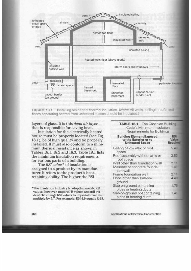
8/19/2019 Applications Electrical
http://slidepdf.com/reader/full/applications-electrical 273/447
unheated
crawl space
or attic
vent
vent-
perimeter
inai
vapour barrier
(on ground)
FIGURE 18.1 Installing residential therm al insulation. {Note: All walls, ceilings, roofs, and
floors separating heated from unheated spaces should be insulated.)
layers of g lass. It is this
dead air layer
that is responsible for saving heat.
Insulation for the electrically heated
ho use must b e properly located (s ee Fig.
18.1),
be of high quality and be properly
installed. It m ust also con form to a mini
mum thermal resistance as shown in
Tables 18.1,18.2 and 18.3. Table 18.1 lists
the minimum insulation requirements
for vario us pa rts of a building.
The
R SI value *
of insulation is
assigned to a product by its manufac
turer. It refers to the product's heat-
retaining ability. The higher the RSI
*The insulation industry is adopting metric RSI
values; however, imperial R values are still evi
dent. To chang e RSI values to im perial R values,
multiply by 5.7. For exam ple, RSI-4.9 equals R-28.
TABLE 18.1 T he C anadian
Building J
Code's Minimum Insulation
Requirements for Buildings
Building Element Exposed
to the Exterior
or
to
Unheated Space
Ceiling below attic or roof
space
Roof assembly w ithou t attic or
roof space
Wall other than foundation wall
Masonry or concrete founda
tion wa ll
Frame foundation wall
Floor, other than slab-on-
ground
Slab-on-ground containing
pipes or heating ducts
Slab-on-ground not containing
pipes or heating ducts
RSI
Va
Requntf
: - .
2 '•
2 '•
4 - :
1.76 3
268 Applications of Electrical Construction
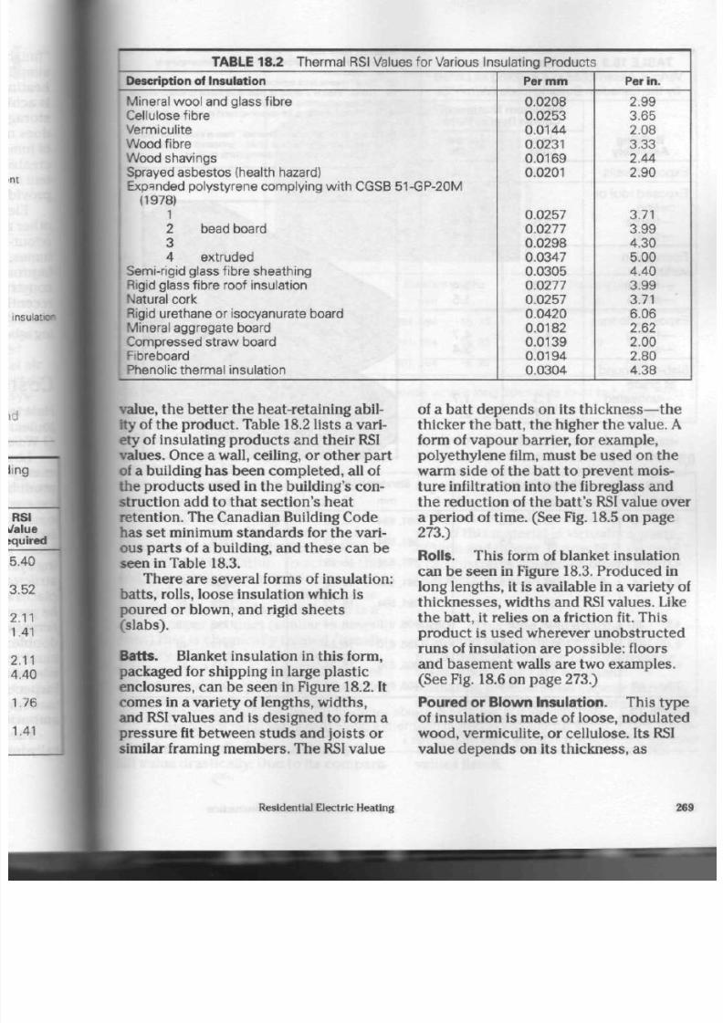
8/19/2019 Applications Electrical
http://slidepdf.com/reader/full/applications-electrical 274/447
TABLE 18.2 T hermal RSI Values for Various Insulating Products
Description of Insulation
Mineral wool and glass fibre
C ellulose fibre
Vermiculite
Wood fibre
Wood shavings
Sprayed asbestos (health hazard)
• Expanded polystyrene complying with CGSB 51-GP-20M
(1978)
1
2 bead board
3
4 extruded
S emi-rigid glass fibre sheathing
Rigid glass fibre roof insulation
N atural cork
Rigid urethane or isocyanurate boa rd
Mineral aggregate board
Compressed straw board
Fibreboard
, Phenolic thermal insulation
Per m m
0.0208
0.0253
0.0144
0.0231
0.0169
0.0201
0.0257
0.0277
0.0298
0.0347
0.0305
0.0277
0.0257
0.0420
0.0182
0.0139
0.0194
0.0304
Pe r in .
2.99
3.65
2.08
3.33
2.44
2.90
3.71
3.99
4.30
5.00
4.40
3.99
3.71
6.06
2.62
2.00
2.80
4.38
value, the better the heat-retaining abil
ity of the prod uc t. Table 18.2 lists a vari
ety of insulating pro du cts and the ir RSI
values. Once a wall, ceiling, or othe r pa rt
of a building ha s been com pleted , all of
the prod ucts used in the building's con
struction add to that section's heat
retention. The C anadian Building Code
has set minimum stan dar ds for the vari
ous parts of a building, and these can be
seen in Table 18.3.
There are several forms of insulation:
batts , rolls, loose insulation which is
poured or blown, and rigid sheets
(slabs).
Batts.
Blanket insulation in th is form,
packaged for shipping in large p lastic
enclosures, can be seen in Figure 18.2. It
comes in a variety of lengths, widths,
and
RSI
values and is designed to form a
press ure fit betwe en st ud s and joists or
similar framing members. The
RSI
value
of a batt d epe nd s on its
thickness—the
thicker the b att, the higher the value. A
form of vapour barrier, for example,
polyethylene film, must be used on the
warm side of the batt to p revent mois
ture infiltration into the fibreglass and
the redu ction of the b att 's
RSI
value ove
a period of time. (See Fig.
18.5
on page
273.)
Rolls. Th is form of blanket insulation
can be see n in Figure 18.3. Produced in
long lengths , it is available in a variety of
thicknesses, widths and
RSI
va lue s. Like
th e batt, it relies on a friction fit. Th is
produ ct is used wherever unob structed
runs of insulation are possible: floors
and basem ent w alls are two exam ples.
(See Fig. 18.6 on page 273.)
Poured or Blown Insulation. This type
of insulation is made of loose, nodulated
wo od, verm iculite, o r c ellulose. Its RSI
value depends on its thickness, as
Residential Electric Heating
26

8/19/2019 Applications Electrical
http://slidepdf.com/reader/full/applications-electrical 275/447
TABLE 18.3
Minim um RSI Values
for
Various Assemblies in a Building as Listed
by the Canadian Building Code (W/m
2
-°C)
Building
Assembly
Exposed walls
Exposed roof or
ceiling
—frame
—solid
Foundation
walls
—frame
—solid
E xposed floors
—frame
—solid
Slab-on-ground
at grade
—unheated
—heated
Maximum Number of
Celsius Degree Days
Up
to
5000
3.0
5.6
3.0
3.0
1.5
4.7
3.0
1.3
1.7
Above
5000
3.4
6.4
3.4
3.4
1.5
4.7
3.4
1.7
2.1
Notes on Table 18.3:
(1) "E xp os ed " means exposed to outdoor temperature or
unheated area.
(2) "S ol id " means brick concrete blocks or concrete.
(3) "Frame" means a wo od or steel stud frame to w hich
n
and exterior cladding is applied.
(4) The RS I value shown for slab-on-ground at grade is for
n
insulation.
15) Slab-on-ground at grade: "heated" means a concrete '<
containing heating ducts or pipes; "unh ea ted " means a
Crete
floor not containing heating ducts or
pipes
(a) Friction Fit Batts
(b)
Value
RSI R
1.4 8
1.7 10
2.1 12
2.4 14
3.5 20
4.9 28
5.4 31
6.1 35
7.0 40
Nominal Thickness
mm in.
65 2.5
89 3.5
89 3.5
89 3.5
152 6
202 8
222 8.75
251 9.87
265 10.37
Standard Widths
mm in.
381,584
15,23
381.584 15.23
381.584
15,23
381,584
15,23
381,584 15.23
406,610
16,24
406,610
16,24
406,610 16.24
406,610 16,™
Standard Lengths
mm in.
1219 48
1219 48
1219 48
1206 47.5
1219 48
1219 48
1219 48
1219 48
1219 48
FIGURE 18. 2
Batt insulation is available in a wi de variety
of
RSI values, thicknesses and
widths. (Note: Some dimensions appear in millimeters rather than in any larger metric unit
because the insulation industry uses millimetres.)
270
Applications of Electrical Construction
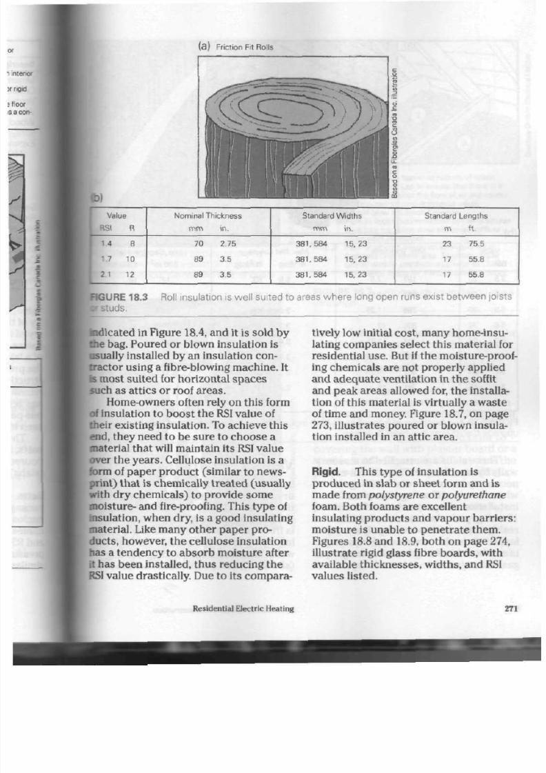
8/19/2019 Applications Electrical
http://slidepdf.com/reader/full/applications-electrical 276/447
Friction Fit Rolls
Value
3SI R
1.4 8
1.7
10
2
1
12
Nominal Thickness
mm in.
70 2.75
89 3.5
89 3.5
Standard Widths
m m in .
381,584 15,23
381,584 15,23
381,584 15,23
Standard Lengths
m ft.
23 75.5
17 55.8
17 55.8
RGUR E 18.3 Roll insulation is we ll suited to areas whe re long open runs exist betwe en joists
j ds .
indicated in Figure 18.4, and it is sold by
the bag. Poured or blown insulation is
usually installed by an insulation con
trac tor using a fibre-blowing m ach ine. It
is mo st suited for horizontal spa ce s
such as attics or roof areas.
Hom e-owners often rely on this form
of insulation to boost the
RSI
value of
their existing insulation. To achieve this
end, they need to be sure to cho ose a
material that will maintain its RSI value
over the y ea rs. Cellulose insulation is a
form of paper product (similar to news
print) tha t is chem ically treate d (usually
with dry chem icals) to provide so me
mo isture- and fire-proofing. This typ e of
insulation, when dry, is a good insulating
material. Like ma ny oth er pap er pro
ducts,
however, the cellulose insulation
has a tend enc y to absor b m oisture after
it has been installed, thu s redu cing th e
RSI value drastically. Due to its compara
tively low initial cos t, m any h om e-insu
lating companies select this material for
residen tial u se. But if the moisture-proof
ing chemicals are not pro perly applied
and ad eq ua te ventilation in th e soffit
and peak a rea s allowed for, the installa
tion of this m aterial is virtually a w aste
of time and money. Figure 18.7, on page
273,
illustrates poured or blown insula
tion installed in an attic area.
Rigid. Th is typ e of insu lation is
produ ced in slab or sheet form and is
made from polystyrene or polyurethane
foam. Both foams are excellent
insulat ing prod ucts and v apou r ba rriers:
mo isture is unable to penetrate them.
Figures 18.8 and 18.9, both on page 274,
illustrate rigid glass fibre bo ard s, with
available thicknesses, widths, and RSI
values listed.
Residential Electric H eating
271

8/19/2019 Applications Electrical
http://slidepdf.com/reader/full/applications-electrical 277/447
(b)
Value
RSI R
3.5 20
4.9 28
5.3 30
5.6 32
6.0 34
6.3 36
6.7 38
7.0 40
8.8 50
Min.
Thickness
mm in.
191 7.5
267 10.5
286 11.25
30 5 12
324 12.75
343 13.5
362 14.25
381 15
470 18.5
Max. Net Coverage
m
2
/bag ft.
2
/bag
5.9 63
4.2 45
3.9 42
3.7 39
3.4 37
3.3 35
3.1 33
2.9 31
2.4 26
Min.
Bags per
UtK
1 0 0 m
2
10001
17 16
24
22
25.5
24
27.5 25.5
29 27
31
28.5
32.5
30
34 32
42 39
FIGURE 18.4 A nodulated form of glass fibre insulation is frequen tly blown in attic
are;
upgrade the RSI value in older buildings.
These slabs are attached to masonry
walls by an adhesive. The adhesive is
necessary in commercial buildings
where no wood framing is presen t.
Installation of a protective surface
of
13 mm gypsum board or similar fire-
resistant product over the polystyrene
insulation is also necessary. Polystyrene
is combustible and gives off a dangerous
gas when ignited.
Vapour Retarders
Insulation traps dead air only when
dry and free from moisture. If the
tion is damp, it will conduct heat
the building
quickly.
The greatest
is from excess moisture inside the
ing trying to escape outside through
walls.
Moisture from cooking, bathin
(showers), and people must be remc
272
Applications of Electrical Construction

8/19/2019 Applications Electrical
http://slidepdf.com/reader/full/applications-electrical 278/447
IGURE
18.5 A wall section show ing
iction-fit batt or roll insulation installed
Breath a vapour barrier and plaster board
FIGURE 18.6 Installation of friction fit rolls
- open run areas. [Note: Be sure to wear a
protective mask and protective clothing.)
u Step
1.
Place air-vapour barrier at bottom of space
jg between
joists.
Lap to ensure that there is a
good barr ier against t he f low of a i r and vapour.
S
S t ep 2. For requ i red t herm al res is t an ce va lue ,
a p o u r o r b l o w i n s u l a ti o n b e t w e e n
o j o i s t s t o d e p t h r e c o m m e n d e d b y m a n u f a c t u r e r .
IS
Take care insu la t ion doe s not cover sof f i t or
Jj
under-eave ventilators.
S tep 3. Rake or smooth insulation to ensure equal
thickness over entire area. To obtain proper
settled density and thickness, refer to CMHC
acceptance listing for manufacturer's product.
F I G U R E 1 8 . 7
insulation
P rocedure for installing loose
safely. Oth erw ise, it will co nd en se on th e
walls, form drops, and run down, which
often damages wall surfaces.
To keep insulation reason ably dry,
the vapour retarding barrier must be
installed on the warm side of the insula
tion, tha t is, between the
plaster
or pan
elling of the wall and the insulation
itself
A
continu ou s, 0.2 mm poly ethylen e film
is fastened over the insulation prior to
covering t he w all with
plaster
board or a
similar finish. Figure 18.10 illustrate s th e
pro per location of a vap our retarding
barrier.
When installing the film, do not
pu nctu re it in any way and b e sure to
secu re it properly with sta ples . In this
way you will prevent air flow th rou gh
tiny open ings o r crac ks. Air tend s to find
any weak spo t, such as the hole in a bal
loon, regardless of the sp ot's location.
Residential Electric Heating
27
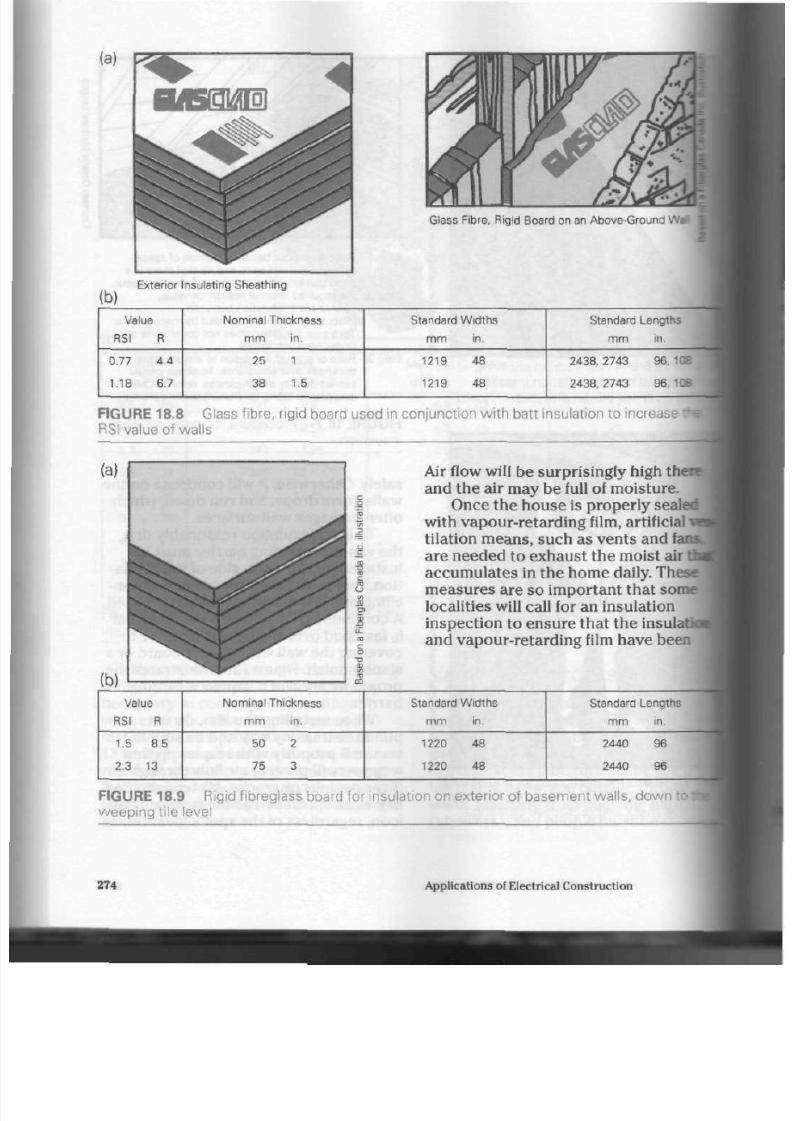
8/19/2019 Applications Electrical
http://slidepdf.com/reader/full/applications-electrical 279/447
(a)
(b)
Exterior Insulating Sheathing
Glass Fibre, Rigid Board on an Above-Ground
\
Value
RSI R
Nominal Thickness
mm in.
Standard W idths
mm in.
Standard Lengths
0.77
1.18
4.4
6.7
25
38
1
1.5
1219
1219
48
48
2438, 2743
2438, 2743
96,106
96,108
FIGURE 18.8 Glass f ibre, r ig id board used in con junc t ion wi th ba t t insulat ion to increase •
RSI value of wal ls
Air flow will be surprisingly high tht
and the air may be full of moisture .
Once the house is properly sealed
with vapour-retarding film, artificial j
tilation means, such as vents and fa
are needed to exhaust the moist air
I
accumulates in the home
daily.
These
measures are so important that some
localities will call for an insulation
inspection to ensure that the insulat
and vapour-retarding film have been
Value
RSI R
1.5 8.5
2.3 13
FIGU RE 18.S
w eeping t i le
N ominal T hickness
mm in.
50 2
75 3
Standard Widths
mm in.
1220 48
1220 48
Standard Lengths
mm in.
2440 96
2440 96
Rigid f ibreglass board for insulat ion on exter ior of basement wal ls , d o w n j H
evel
274
Applications of Electrical Construction

8/19/2019 Applications Electrical
http://slidepdf.com/reader/full/applications-electrical 280/447
insulation
Air barrier/vapour
retarder prevents
moisture from
inside air coming
into contact with
concrete.
Residential Electric Heating

8/19/2019 Applications Electrical
http://slidepdf.com/reader/full/applications-electrical 281/447
properly installed and not damaged by
other building trade areas.
Remember basement walls because
if they are insulated there will be a
higher degree of comfort in the hom e.
These walls must be pro tected from
moisture produced both inside and out
side the building, however. Figure
18.11
illustrates a basem ent wall section and
the methods used to prevent dam pness
from entering and spoiling the wall's
insulation.
Ventilating Devices
Ventilating fans are placed over stoves
and in bathroom s to remove excess
moisture. They also, however, remove
some of the heat from the house, and so
Methods of providing adequate air-flow
ventilation into attic areas
method A
o
i
8
gable end, ridge
or roof vents
NO TE : Under-eave vents should provide 50% venting area.
Gable end, ridge, or roof vents should provide other 50% venting area.
FIGURE 18.12 A t t ic v ent i la t ion. P rov ide a m in im um of 1 m
2
f ree (unobstructed) vent i la
tor each 300
m
?
insulated cei l ing area. Cathedral - type and low-pi tched roofs require
1
rr
t ion for each 150 m
2
insulated at t ic area. Dis t r ibut ion of vents must prov ide cross-
v ent i la t ion in a t t i c f rom end t o end and f rom t op t o bot t om.
276
Applications of Electrical Construction

8/19/2019 Applications Electrical
http://slidepdf.com/reader/full/applications-electrical 282/447
should not be used continuously. These
tans are an important part of the heating
installation an d a re looked for by electri
cal heating in spec tors.
Attic insulation must a lso be k ept
moisture-free. Having a system of vents
placed in various pa rts of the attic will
achieve this. One sq uare m etre of vent is
required for each 150/300 m
2
of atti c
area . (See Fig. 18.12) Th e circu lation of
air tend s to keep the insulation d ry and
moisture-free. Remember that a cold
attic during the winter indicates that the
insulation is indeed w orking and keeping
beat in the h ou se.
Baseboard Heater
One of the m ost com mo n ty pes of elec
trical heating unit is the baseboard
heater. It co nsis ts of an enclosed heating
itlement, fitted with h eat-radiating metal
Mns
and su pp ort ed in a metal frame. It
ope rates on the principle that air heated
by the elem ent w ill rise and flow ou t of
th e top of the frame, w hile coole r air will
be drawn from the floor area into the
bottom of the heater. This process is
called convection of air. (See Fig. 18.13)
Baseboard heaters are rated in both
wattage and voltage. The m ost comm on
unit for residential use is the 240 V
heater, simply be cau se a 240 V he ate r of
a given wa ttage re quires half as m uch
current as a 120 V hea ter of the sam e
wattage. The need for extra large con
ducto rs in the heater circuits is reduced .
Baseboard heaters are made in low
and standard
wattage
densities. A
1000 W
hea ter in a low-watt density will be
approximately 1.8 m long and low
enough in surface temperature that it
may be installed safely under drapes
and other heat-sensitive m aterials. It is
suitable for use under heat-sensitive
synthetic fabrics, which shrink, lose
their shape, or discolour when exposed
to heat for a prolonged period of tim e.
A 1000 W heater in a standard w att
density will be approximately 1.2 m long
and reach a higher surface tem pera ture.
The heat is more concentrated, and so
this type of heater should
not
be used
und er o r nea r delicate fabrics. It is excel
lent, however, for use in are as w here
space is limited and higher surface tem
peratures are not a problem.
Draperies should be hung with th e
nearest fold at least 5 cm away from the
he ate r and 4 cm off th e floor. Prop er air
circulation through the heater is then
possible.
Baseboard heate rs are produced in a
variety of wattage ranges, star ting as low
as 250
W
and going as high as 3000
W.
Manufacturers provide specifications for
their own products.
Installation of Baseboard Heaters.
These heaters should be mounted at the
finished floor level to allow th e cool a ir
to enter the heater
easily.
Also, the y
must be mounted on a flat surface,
without bending or distorting the h eater
frame. If the frame is distorted in any
way, the heater
will
produce som e noise
as it expand s and con tracts during its
heat cy cles.
The hea ter is secure d to the wall
with several w ood screws. It needs
nearly no maintenan ce, except for an
occasional vacuum ing to remov e lint col
lected on the heater fins. Lint slows the
convection of air throug h the h eater and
low ers i ts efficiency. (See Figs. 18.14 and
18.15)
Radiant Heating for
Ceil ings
An other ty pe of electrical heating unit is
the radiant-heating ceiling cable. This
Residential Electric Heating
277
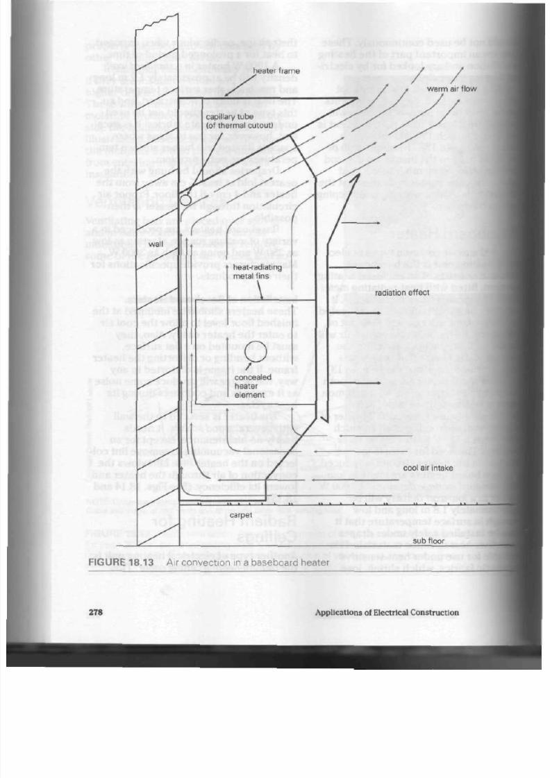
8/19/2019 Applications Electrical
http://slidepdf.com/reader/full/applications-electrical 283/447
FIGURE 18.13 A ir convection in a baseboard heater
278
Applications of Electrical Construction
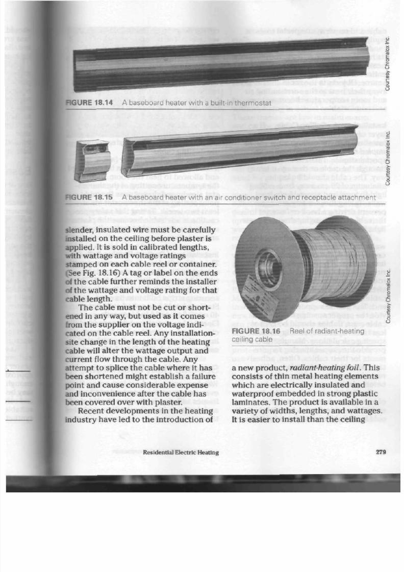
8/19/2019 Applications Electrical
http://slidepdf.com/reader/full/applications-electrical 284/447
RGURE 18.14 A baseboard heater with a built-in thermos tat
RGURE 18.15 A baseboard heater w ith an air conditioner switch and receptacle attachment
slender, insulated w ire must b e carefully
installed on the ceiling before
plaster
is
applied.
It
is sold in calibrated leng ths,
with wattage and v oltage ratings
stamped on each cab le reel or container.
(See Fig. 18.16) A tag or label on the end s
of the cable further rem inds th e installer
of the wattage and voltage rating for tha t
cable length.
The cable mu st not be cut or sho rt
ened in any way, but used as it co m es
from the su pplier on th e voltage indi
cated on t he ca ble reel. Any installation-
site change in th e length of the heatin g
cable will alter th e wattag e ou tpu t and
current flow throu gh the ca ble. Any
attempt, to splice the cab le where it ha s
been shortened might establish a failure
point and cause considerable expense
and inconvenience after the cable has
been covered over with plaster.
Recent developments in the heating
industry hav e led to the introduction of
FIGURE 18.16 Reel of radiant-heating
ceiling cable
a new product, radiant-heating foil. This
con sists of thin metal heating elem ents
which are electrically insulated and
waterproof embedded in strong plastic
lamin ates. The pr od uct is available in a
variety of w idths, lengths, and wa ttages.
It is eas ier to install tha n th e ceiling
Residential Electric Heating
279

8/19/2019 Applications Electrical
http://slidepdf.com/reader/full/applications-electrical 285/447
cable and requires no special tools or
equipment.
Any ceiling heating system radia tes
its heat energy into a room, warming any
heat-absorbing object present. The
entire ceiling, therefore, beco me s a hea t
sou rce. Objects in the room start to give
away their heat to the surroun ding air
and room tem perature becom es even
and comfortable.
Installation of a Ceiling Cable. If a
layer of drywall plaster has been
installed first, the ceiling cable can be
stapled d irectly to th e drywall with
special staple s. Take care not to staple
through the cable or dam age it in any
way. The cable should be kept a
minimum of 20 cm away from ceiling
light fixtures and about 15 cm from
walls. Taking thes e safety m eas ure s will
prevent driving a hook or fastener into
the cable when hanging dra pe s or new
light fixtures.
If a building has pou red co nc rete
walls and ceilings or a similar m aso nry
con struc tion , the ceiling cable will need
hanger strips. The se plastic strips are
run across the ceiling at each end of the
room, secured to the ceiling with ad he
sive, and then fitted with the heating
cable. The cable is looped from end to
end. The plastic supporting s trips pro
vide the proper spacing between the
cable run s. Cables should be kept a t
least 5 cm a part, depending on cable
spacing calculations. Manufacturers will
provide the p roper spacing require
ments for their cables. Often, adhesive
tape is needed at intervals in a long
room to prevent sagging of the cables
before plastering.
Each cable set c om es with a length
of heavily insulated con duc tor at each
end of the cable. Such a length is called a
cold
lead.
Cold leads are run from th e
ceiling down to an electrical box on
I
wall where the therm ostat and/or |
supp ly is located. The length of these |
leads should
not
be changed.
To ensu re tha t th e cable is not
nicked or damaged with a trowel,
based
gypsum plaster
must be
inste
in the ceiling carefully. The
plaster i
be allowed to dry fully before the
i
is energized. Take ca re to ch eck the
cable for continuity both before and
after plastering . Using the c able to
i
the plaster will only result in shrink
and /or cracking of the plaster aroi
the heating cable.
Once the plaster is dry (allow at
least a week), th e cab le can be ener
and allowed to heat the room . Inci
the tem pera ture setting of the ther
sta t slowly, and d o not pa ss the m id
point setting of the thermostat for at
least two we eks. Taking this safety |
caution is advisable beca use the
pla
may n ot be thoro ugh ly d ry in all ceili^
areas.
Installation of Radiant-Heating
Foil.
Th e foil is rolled ou t to th e p rop er
leoj
as supplied by the manufacturer,
without cuts or splices m ade to it. Th
unit is the n stapled to a joist, using
da
securing strips built into its edge.
Staples shou ld b e applied at 30 cm or
40 cm (12 in. or 16 in.) interv als.
Electrical connections are made in a
clear-cover connection box for easy
inspection prior to covering with the
ceiling mate rial. (See Fig. 18.17)
Specific Heat Loss A rea*
Windows are major heat loss areas,
ever, proper caulking around windc
frames will stop infiltration of cold I
and drafts and save heat over a per
time.
280
Applications of Electrical Construction

8/19/2019 Applications Electrical
http://slidepdf.com/reader/full/applications-electrical 286/447
of
FIGURE 18.17 Installation of radiant-heating
For many years, it was com mon prac
tice to install wooden or aluminum
storm window s over existing window
openings in older homes. Aluminum-
framed windows were neat and easily
removed for cleaning and ma intenan ce.
They also did not require painting and
did not swell or jam from moisture
intake. The alum inum frame, however,
was a good cond uctor of heat and
passed this heat from the building's inte
rior to the o utsid e. Wood-framed win
dows required more maintenance, were
heavier to remove and install, and were
often difficult to open and close after a
few years. But th e wo oden frame did
retain heat much better than an alumi
num frame.
Now, with window deve lopm ents
keeping pace with other design improve
ments in the building industry, double
and triple
pane
window units are availa
ble. The herm etically sea led pa ne s of
glass create a dry air spa ce between the
panes.
They make heat retention possi
ble and the inconvenient removal, clean
ing and installation of stor m window
•nits unnecessary.
A further design improvement is spe
cially treated glass which can be pur
chased as part of dou ble and triple pane
window u nits. The glass limits ou tward
heat flow in th e winter and inward heat
flow during the sum mer even more th an
the stand ard d oub le or triple pane units.
Some window u nits have aluminum
frames designed to support the glass
without being in actual contact with it.
Th ese frames a re low in m aintenance
and can be obtained with section s that
open for cleaning or fresh air entry.
Modern window units may also have
wood en frames. In many case s, thes e
frames are covered with a plastic mate
rial to eliminate moisture intake and the
need for painting the wood.
Fireplaces
are attractive and give off
much heat when operating. When not
operating, however, they allow a great
deal of heat to be drawn out of the room,
up th e flue, and out th e chimney. A brisk
wind across th e chimney will speed heat
removal from the room. To prevent this,
the fireplace damper should always be
well-fitted and kept closed when the fire
place is not in us e. A se t of well-fitting
do ors to cover the fireplace's opening
will further aid heat retention when no
fire is burning in the unit. (See Fig. 18.18)
Many typ es of fuel-efficient fireplace
inse rts a re ava ilable for installation in
new or existing fireplaces. These mod
ern produc ts enhance a room's appear
ance and help heat the home when the y
are in use. They also provide sup erior
protection from heat loss when not in
use.
Another po ssible cause of heat loss
is carelessly installed insulation around
pipes and
electrical
boxes
within walls
and ceiling area s. Cold air will infiltrate
thes e weak spots; therefore, extra care
should be taken to ens ure a prop er fit
around boxes and plum bing pipes. As
Residential Electric Heating
281

8/19/2019 Applications Electrical
http://slidepdf.com/reader/full/applications-electrical 287/447
FIGURE 18.18 A fireplace should have a
tight damper and a glass screen for effective
heat retention.
FIGURE 18.19 W hen installing plumbing
and wiring , particular attention should be
given to the installation of insulation. Insula
tion shou ld com pletely fi l l any cavities.
insulation —•
" S .
- a
founds:-
wall
— footing
insulation
FIGURE 18.20 Insulation on the outs
face of a slab on grade
mentioned in Chapter
7,
special pi
forms are available to prevent air I
age around wiring poxes. Figure 18.1
illustrates the insulation required
around such a box.
A house built on a concrete slab a
pad is vulnerable to heat loss, and
requires placement of a rigid exterior
type of insulation around various sec
tions of the slab and its footings. (See
Fig. 18.20) The insulation will prevenl
heat from radiating out of the slab I
into the cool earth.
282
Applications of Electrical Construction
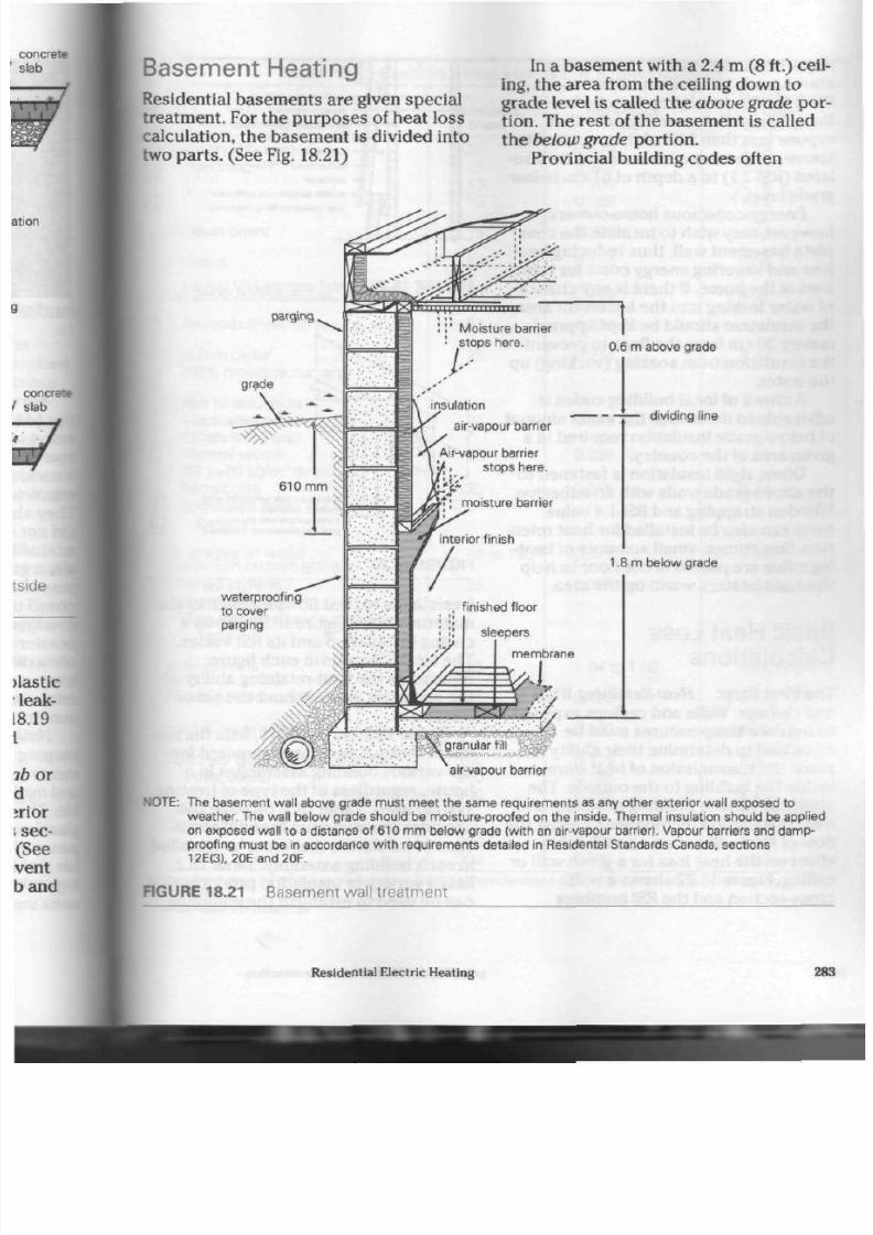
8/19/2019 Applications Electrical
http://slidepdf.com/reader/full/applications-electrical 288/447
Basement Heating
Residential basements are given special
treatment. For the purposes of heat loss
calculation, the basement is divided into
two par ts. (See
Fig.
18.21)
In a basement with a 2.4 m (8 ft.) ceil
ing, the area from the ceiling down to
grade level is called th e above grade por
tion. The rest of the basement is called
th e below grade portion.
Provincial building codes often
pargmg
I ' Moisture barrier
stops here.
insulation
air-vapour barrier
Air-vapour barrier
stops here.
moisture barrier
0.6 m above grade
dividing line
1.8 m below grade
waterproofing
to cover
parging
sleepers
membrane
air-vapour barrier
N O T E : The basement wall above grade must meet the same requirements as any other exterior wall exposed to
weather. The wall below grade should be moisture-proofed on the inside. Thermal insulation should be applied
on exposed wall to a distance of 610 m m below grade (w ith an air-vapour barrier). Vapour barriers and damp-
proofing must be in accordance with requirements detailed in Residental Standards Canada, sections
12E(3), 20E and2 0F.
FIGURE 18.21 Basement wall treatm ent
Residential Electric Heating
28

8/19/2019 Applications Electrical
http://slidepdf.com/reader/full/applications-electrical 289/447
require bas em ent walls that are 50%
above grade to have a minimum of
RSI-2.1
value insulation installed over
the entire wall. Basement walls that
expo se less than
50%
of their surface to
above-grade temperatures must be insu
lated (RSI-2.1) to a de pth of 61 cm below
grade level.
Energy-conscious hom e-owners,
however, may wish to insulate the com
plete basem ent wall, thus reducing he at
loss and lowering energy costs for this
area of the hom e.
If
there is any c han ce
of water leaking into the basement area,
the insulation sho uld be kept approxi
mately 30 cm from th e floor to p reve nt
th e insulation from soaking (wicking) up
the water.
A
check of local building cod es is
advisable to determine the exact amount
of below-grade insulation required in a
given area of the country.
Often, rigid insulation is fastened to
the ab ove-grade walls with an a dhesive.
Wooden strapping and
RSI-1.4
value
batts can also be installed for heat reten
tion. Sometimes, small amo unts of h eat
ing cable a re placed in th e floor to help
the main heaters warm up the area.
Basic Heat Loss
Calculations
The First
Step: Heat-Retaining Walls
and
C eilings.
Walls and ceilings exp osed
to outdoor temperatures must be
examined to determ ine their ability to
resist the transmission of heat from
inside the building to the o utside. T he
ability of various building products and
their installation techn ique s to resist th e
flow of hea t will hav e a con side rab le
effect on the heat loss for a given wall or
ceiling. Figure 18.22 sh ow s a w all
cross-section and the
RSI
num bers
inside surface (still air)
gypsum wallboard - 13 m m
weatherproof sheathing - 11 m m
asbestos finishing felt
air space
backer board - 10 m m
clapboard
outside surface - 24 km/h wind
total resistance (exci. insulation)
FIGURE 18.22 Wa ll section RSI values
^
*— outside surface (ventilated attic)
—
gypsum wallboard -
13
m m
inside surface (still air)
total resistance (excl. insulation)
FIGURE 18.23 Ceiling section RSI vali
(res istan ce to heat flow) for each of
thi
materials used . Figure 18.23 shows a
ceiling installation and its RSI values.
The total RSI value in eac h figure
repre sents the heat-retaining ability
of
the ma terials used w ithout th e aid of
insulation.
Table
18.3,
on page
270,
lists the
i
imum
thermal resistance required for
the various building assem blies in a
hou se, regardless of the type of heat
system used. Table
18.1,
on page 268,
provid es the minimum therm al resist
anc e of insulation th at m ust be insta
in each building assembly. Table 18.2
lists a variety of insulation products i
can be used t o establish the minimum
284
Applications of Electrical Construction

8/19/2019 Applications Electrical
http://slidepdf.com/reader/full/applications-electrical 290/447
TABLE
18.4
Resistance Values for Various Building Materials
;
Building Material
Insulating fibreboard
sheathing
Gypsum board
Plywood
Hardwoods (Maple, oak, etc.)
Softwoods (Pine, fir, spruce, etc.)
We stern cedar
(18% moisture content)
Loose fill insulation
Macerated paper
•(Cellulose fibre)
Mineral wools
(32 to 8 0 kg/m
3
den sity)
Vermiculite
(Expanded mica) 112 kg/m
3
density
A ir spaces (in walls)
Foamed styrene
(Density 26 kg/m
3
)
(See ma nufacturer's specifica
tions)
Polyurethane
Flooring (Hardwood)
Brick (C lay or shale)
Concrete block (Sand and gravel,
3 oval cores)
Cinder block
Thickness
(mm)
25
15
13
13
25
13
25
25
25
25
25
25
20 to 100
25
25
20
100
100
200
300
100
200
300
Resistance
Factor
0.419
0.262
0.209
0.056
0.220
0.110
0.160
0.220
0.274
0.628
to
0.704
0.586
0.366
0.171
0.608
to
0.704
1.04 to 1.06
0.120
0.060
0.125
0.195
0.225
0.195
0.303
0.333
Heat
Loss
Factor
(W/m
2
C)
2.38
3.82
4.78
17.85
4.54
9.09
6.25
4.54
3.64
1.59 to 1.42
1.71
2.73
5.85
1.64 to 1.42
0.96 to 0.94
8.33
16.66
8.00
5.13
4.44
5.13
3.30
3.00
Values shown above are taken from the Acceptable Building Material Systems & Equipment—Central Mortgage and Housing
Corporation.
'Illinois Institute of Technology
Residential Electric Heating

8/19/2019 Applications Electrical
http://slidepdf.com/reader/full/applications-electrical 291/447
therm al resistan ce as listed in Table
18.1.
Additional information on the qual
ity and
RSI
value of the insulation ca n be
obtained from the manufacturers on
request.
For com parison pu rpos es, the RSI
value of variou s building pro duc ts can
be lo cated in Table 18.4. More c om plete
tables can usually be obtained from the
local hyd ro utility, electrical leag ue, or
building product supplier.
The Second Step: Heat Loss Through
Walls and C eilings. The second step in
determining the amount of heat needed
for a hou se is to calculate th e heat lost
thro ug h th e walls and ceilings. To do
this, the RSI total of the wall or ceiling
must be mathematically converted to a
U factor. The U factor (overall
co-efficient of heat transfer) is the
amount of heat transmitted through a
heat ba rrier in one hour per squ are
metre of surface for each 1°C of
temperature difference between the
inside and outside of the barrier.
Table 18.5 lists outside tem per ature s
experience d in selected Canadian loca
tions, along with the num ber of degree
day s below 18°C. Th ese figures are
based on
2.5%
of the Janu ary outd oor
tem peratu res recorded in thos e areas of
the country.
For example, an exposed wall listed
in Table 18.3 mu st h ave an
RSI
value of at
least 3.0 when its insulation an d all as
sembly produc ts are considered. The
U
factor eq uals one third, or 0.333 W/m
2
for
each
1°C
of
design temperature difference.
If
the hou se with this wall were in the
Toronto region of Ontario, the ou tdo or
design temp eratu re would be -18°C, and
the degree days would be 4082 (under
5000 as requ ired by Table 18.3). If th e
occupants want an indoor temperature
of
23°C,
the design tem per atur e differ-
286
ence would be
23°C
-
(-18°C) =
41°C.
If the
U
factor for a 1°C temperature)
difference is
0.333
W /m
2
, then the heat
loss for a 41°C tem pe rat ur e difference
will be
41
x
0.333
W/m
2
, which equals
13.65 W /m
2
or approximately 14
W
The h eat lost thro ugh the ceilings
i
calculated in much t he sam e way as
lost through the w alls.
To find th e total hea t loss through
walls of a roo m, t he tota l area of wall
exposed to cold air must be calculate*
To do so , multiply the h eight of the roa
by the length of the exposed wall.
(Remember that a corner room has tvd
exposed walls.) Figure 18.24, on page
290, sho w s a wall with a g ross area
high time s 4.6 m long, which is abo
11.04
m
2
. Since th e window occup ies
0.72 m
2
of spa ce, the ne t expo sed wal i
about 10.3
m
2
.
Th e amo unt of heat loa
through this wall in an hour is equr
lent to 14 W/m
2
x 10.3
m
2
,
which is
144.2 W
The Third
Step: Heat Loss Through
Doors and W indows.
Tab le 18.6, on
page
291,
lists the he at loss per
squaiej
m etre throu gh various typ es of door
tm
window installations for each degree •
design tem pe rat ur e difference. If the
room show n in Figure 18.24 ha s a
wood
framed window, that is,
single-glazed
with a storm , the he at loss will be
2.90 W /m
2
of window for e ach degre*
design tem per atur e difference. The
ti
heat loss throug h the g lass will be as
follows. Th e area of the window equa
0.6
m
x 1.2
m,
which is 0.72
m
2
.
Therefore, the heat loss per degree
Celsius will be 0.72
m
2
x 2.90 W/m
2
,
wh ich is 2.09 W /m
2
. W ith a
temperatu
difference of 41°C, th e h ea t lo ss will
t
41 x 2.09 W/m
2
, which is 85.7 W This
heat loss is added to the 144.2
W
lost
through the exposed wall.
Applications of Electrical Construction

8/19/2019 Applications Electrical
http://slidepdf.com/reader/full/applications-electrical 292/447
TABLE 18.5 Design Data fo r Selected Locations in Canada
Province
and
Location
Design Degree
Temp-
Days
era-
Below
ture 18°C
2.5%
X
British Columbia
Abbotsford - 10
nftoassiz
- 13
Afcerni
- 5
| Ashcroft
- 2 5
Bearton River - 3 7
Burns Lake - 3 0
Cache Creek - 25
Campbell
River...
- 7
Carmi - 2 4
Castlegar
- 1 9
Chetwynd - 35
Chilhwack - 12
Ooverdale - 8
Comox
- 7
I Courtenay
- 7
Cranbrook - 2 7
Crescent Valley
. . -2 0
Crofton
- 6
Dawson
C reek. .. -3 6
Dog
Creek
- 2 8
Duncan
- 6
Elko
- 2 8
I Femie
-29
• j r t Nelson - 4 0
Port
S t.
John
- 3 6
3'acier - 27
MuMen -28
Grand Forks
- 2 0
Greenwood - 2 0
Haney - 9
Hope
- 1 6
Kamloops
- 2 5
Kaslo
- 23
Kelowna
- 17
Kimberley
- 2 6
Kitimat Plant
- 16
Kitimat
Townsite
- 16
Langley
- 8
Lillooet
- 2 3
Lytton
- 1 9
Mackenzie
- 3 5
McBride
- 3 4
McLeod Lake
- 35
Masset
- 7
Merritt - 2 6
Misson City
- 9
Montrose - 17
Nakusp - 24
Nanaimo - 7
Nelson - 20
New
Westminster
North
Vancouver - 7
Ocean Falls - 12
100 Mile House.. -2 8
Osoyoos
- 1 6
Penticton - 1 6
PortAlberni - 5
Port Hardy - 5
Port McNeill - 5
Powell River 9
Prince
George....
33
Prince Rupert
14
3150
296
3180
4 6
7010
572
4 8
32
5210
3747
589
297
3 3
32 3
325
4762
432
3140
589
5110
32
49
498
7 63
6119
573
495
4 5
452
328
3150
3756
4110
368
489
4110
4130
298
4130
322
595
572
572
372
4190
298
4 8
4130
3010
392
8 293
3 9
352
49
353
3514
3180
3661
348
29
5388
4117
Princeton
Oualicum Beach
Quesnel
Revelstoke
Richmond
Salmon
A rm
Sandspit
Sidney
Smithers
Smith River
Squamish....
Stewart
Taylor
Terrace
Totino
Trail
Ucluelet
Vancouver...
Vernon
Victoria
Williams
Lake.
Youbou
Alberta
Athabasca
Banff
Barrhead
Beaverlodge
Brooks
Calgary
Campsie
Camrose
Cardston
Claresholm
Cold Lake
Coleman
Coronation
Cowley
Drumheller
Edmonton
Edson
Embarras
Portage
Fairview
Fort
Saskatchewan
Fort
Vermilion..
Grande Prairie
Habay
Hardisty
High River
Jasper
Keg
River
Lac La Biche...
Lacombe
Lethbridge
McMurray
Manning
Medicine Hat .
Peace
River...
Penhold
Pincher Creek ....
Ranfurly
Red Deer
Rocky Mountain
House
Slave Lake
Stettler
Stony Plain
Suffield
- 27
- 7
- 3 3
-26
- 7
-23
- 6
- 6
- 2 9
- 4 6
-11
- 2 3
-36
-20
- 2
- 17
- 2
- 7
- 2 0
- 5
- 3 1
- 5
- 3 5
- 3 0
- 3 4
- 3 5
- 3 2
- 31
- 3 4
- 3 3
- 3 0
- 31
- 3 6
- 31
- 31
- 3 1
- 31
- 3 2
- 3 4
- 41
- 38
- 4 1
- 3 6
- 4 1
- 3 3
-31
-32
-40
-35
-33
-30
- 3 9
- 3 9
- 31
- 3 7
- 32
- 3 2
- 3 4
- 3 2
- 31
- 3 6
- 3 2
- 3 2
- 3 2
456
325
494
4 73
292
4 9
365
3 9
529
7610
3140
4710
589
443
325
365
325
3 7
4 4
3 76
5105
336
628
5719
6
582
529
5345
6010
572
483
5120
645
5120
59 6
5150
557
5589
5910
749
6170
32
589
7170
6145
7 5
595
532
5532
682
6140
574
4718
6778
66
4874
6424
5845
5010
598
57
555
622
5590
5780
5360
Taber
Turner
Valley...
Valleyview
Vegreville
Vermilion
Wagner
Wainwright . . . .
W et ask iw in. . .
Whitecourt
Wimborne
Saskatchewan
Assiniboia
Battrum
Biggar
Broadview
Dafoe
Dundurn
Estevan
Hudson Bay
Humbolt
Island Falls
Kamsack
Kindersley
Loydminster
Maple Creek
Meadow Lake ...
Melfort
Melville
Moose Jaw
Nipawin
North Battleford
Prince Albert
Qu'Appelle
Regina
Rosetown
Saskatoon
Scott
Strasbourg
Swift
C urrent .
Uranium
C i ty..
Weyburn
Yorkton
Manitoba
Beausejour
Boissevain
Brandon
Churchill
Dauphin
Flin Flon
Gimli
Island Lake
Lacdu
Bonnet.
Lynn Lake
Morden
Neepawa
Pine Falls
Portage
la
Prairie
Rivers
St. Boniface.
S t.
Vital
Sandi
lands...
Selkirk
Split Lake
Steinbach
Swan
Rver.
.
The Pas
Thompson....
- 31
- 3 1
-37
-34
-35
- 36
- 3 3
- 3 3
- 35
- 3 1
- 3 2
- 32
- 34
- 34
- 3 6
- 3 5
- 32
- 37
- 3 6
- 3 9
- 3 5
- 3 3
- 35
- 3 1
- 3 6
- 37
- 3 4
- 32
- 3 8
- 3 4
-37
-34
-34
-33
- 35
- 34
- 34
- 32
-44
- 33
- 3 3
- 32
- 3 3
- 3 9
- 3 3
- 3 8
- 34
- 3 6
- 34
-40
-31
- 3 2
- 34
- 31
- 3 4
- 33
- 33
- 32
- 33
- 38
- 33
- 36
- 36
- 42
4750
5700
6110
6000
6140
6180
6000
5670
6130
5620
5340
5400
5890
6080
6360
5840
5542
6470
6280
7100
6290
5710
6280
5180
6550
6390
6170
5400
6550
6050
6562
6060
5920
5860
6077
6260
5890
5482
8210
5720
- 3 4
6239
583
5610
6 37
9213
6150
678
6 3
7210
595
782
549
595
6
589
594
583
583
589
589
788
583
628
6852
793
287

8/19/2019 Applications Electrical
http://slidepdf.com/reader/full/applications-electrical 293/447
Transcona
- 33
Virden - 3 3
Whiteshell - 3 4
Winnipeg - 3 3
Ontario
Ailsa Craig - 1 7
Ajax
- 2 0
Alexandria - 2 4
Alliston
- 2 3
Almonte - 2 6
Ansonville
- 33
Armstrong
- 39
Arnprior
- 27
Atikokan - 34
Aurora - 21
Bancroft - 27
Barrie
- 2 4
Barriefield -22
Beaverton - 24
Belleville
- 2 2
Belmont
- 17
Bowmanville - 20
Bracebridge - 26
Bradford
- 23
Brampton - 1 9
Brantford
- 1 7
Brighton - 21
Brockville
- 2 3
Brooklm - 20
Burks Falls - 26
Burlington - 17
Caledonia
- 17
Cambridge - 1 8
Campbellford
- 23
Camp Borden
- 23
Cannington
- 24
Carleton Place.... -25
Cavan - 22
Centralia
- 17
Chapleau - 35
Chatham - 1 6
Chelmsford - 28
Chesley
- 19
Clinton - 17
Coboconk
- 25
Cobourg -21
Cochrane - 34
Colborne - 21
Collingwood - 22
Cornwall
- 23
Corunna - 1 6
Deep River
- 2 9
Deseronto
- 22
Dorchester - 1 8
Dorion - 3 3
Dresden - 16
Dryden
- 3 4
Dunbarton - 1 9
Dunnville - 1 5
Durham
- 2 0
Dutton
- 1 6
Earlton - 3 3
Edison - 3 4
Elmvale - 24
Embro - 1 8
Englehart
- 33
Espanola - 2 5
Exeter
- 17
Fenelon Falls - 25
Fergus
- 2 0
Fonthill - 1 5
Forest
- 1 6
Fort Erie - 1 5
5830
5890
5950
5889
3980
4080
4580
4520
4740
6220
6892
4800
6040
4300
4960
4470
4240
4580
4190
3980
4130
4800
4410
4200
3920
4240
4300
4240
5070
3700
3920
4130
4410
4470
4580
4690
4470
3940
5950
3530
5290
4240
4130
4740
4190
6230
4190
4580
4470
3810
5180
4080
4030
5890
3700
6080
4030
3810
4620
3750
5866
6000
4580
4130
5950
5070
4080
4690
4610
3700
3830
3590
Fort Frances
- 33
Gananoque - 2 2
Georgetown
- 1 9
Geraldton - 35
Glencoe
- 16
Goderich - 16
Gore Bay -2 3
Graham - 3 7
Gravenhurst
- 26
Grimsby - 16
Guelph - 1 9
Guthrie
- 2 4
Hagersville
- 1 6
Haileybury
- 32
Haliburton - 27
Hamilton
- 17
Hanover - 1 9
Hastings
- 2 3
Hawkesbury - 2 5
Hearst
- 3 4
Honey Harbour... - 2 4
Hornepayne
- 3 7
Huntsville - 2 6
Ingersoll
- 18
Jarvis - 1 6
Jellicoe
- 36
Kapuskasing
- 33
Kempville
- 25
Kenora
- 33
Killaloe - 2 8
Kincardine
- 17
Kingston - 22
Kinmount - 2 6
KirklandLake - 33
Kitchener
- 1 9
Lakefield - 2 4
Lansdowne
House - 3 9
Leamington
- 1 5
Lindsay - 24
Lions Head
- 1 9
Listowel - 19
London - 18
Lucan - 17
Mailand
- 23
Markdale - 20
Martin - 3 6
Matheson
- 33
Mattawa
- 2 9
Midland - 2 3
Milton - 1 8
Milverton
- 1 9
Minden - 2 6
Mississauga - 1 8
Mitchell - 1 8
Moosonee
- 36
Morrisburg - 2 3
Mount Forest
- 21
Muskoka
Airport
- 26
Nakina - 35
Napanee
- 22
Newcastle - 2 0
NewLiskeard - 32
Newmarket - 22
Niagara Falls
- 1 6
North
Bay -2 8
Norwood - 2 4
Oakville
- 1 8
Orangeville
- 2 1
Orillia - 2 5
Oshawa - 19
Ottawa
- 2 5
Owen Sound - 19
5830
4240
4250
6550
3810
4190
4910
6470
4740
3580
4220
4520
3920
5830
4920
3710
4350
4470
4800
6500
4580
6580
4760
4030
3860
6450
6366
4540
5932
4940
4240
4266
4800
6150
4110
4630
7110
356
458
435
463
4 68
4 3
43
469
633
622
534
458
4 8
452
485
3810
44
6931
441
4755
4837
654
413
4130
583
4350
3740
5318
4520
3640
4650
4610
4130
4673
4220
Pagwa River - 3 *
Paris - 17
Parkhill - 16
Parry Sound
- 24
Pembroke - 28
Penetanguisbene
- 23
Perth - a
Petawawa
-29
Peterborough -23
Petrolia - * •
Picton - 21
Plattsville
- 18
Point
Alexander.. - 29
Porcupine - 34
PortBurwell
- 1 5
Port Colborne
- 15
Port Credit
- 18
Port Dover - 15
Port Elgin
- 17
Port Hope - 21
Port Perry -22
Port Stanley - 15
Prescott
- 23
Princeton - 17
Raith - 35
Re d Lake -34
Renfrew
- 27
Ridgeway -15
Rockland
- 26
S t.
Catharines....
- 16
S t.
Marys
-18
S t. Thomas - 16
Sarnia
- 16
Sault Ste. Marie
Schreiber -35
Seaforth - 17
Simcoe
Sioux
L o o k o u t . ..
- 34
Smiths Falls - 25
Smithville
- 16
Smooth Rock
Falls
- 34
Southampton -17
South
Porcupine -34
South River
-27
Stirling
-23
Stratford
- 18
Strathroy - 17
Streetsville
- 1 8
Sturgeon Fal ls. . . -27
Sudbury - 28
Sundridge - 27
Tavistock - 1 8
Thamesford
- 18
Thedford -16
Thunder
Bay -31
Tillsonburg -17
Timagami
-30
Timmins -34
Toronto
- 18
Trenton - 21
Trout Creek
- 27
Trout Lake -38
Uxbridge -22
Vanier
- 25
Vittoria - 15
Walkerton
-18
Wallaceburg - 16
Waterloo
- 19
Watford - 16
Wawa
- 35
Welland - 15
West Lome
- 16
Whitby - 20
288

8/19/2019 Applications Electrical
http://slidepdf.com/reader/full/applications-electrical 294/447
o
-
:
-;•:
:•:
9::
C-J.:
5-5:
4 4 -
1 2 *
' r :
03C
»
57«
3 9 : :
6 5 " :
6181
4082
4 - - - :
5231
768C
4 4 b :
4 t : - .
386C
416C
362".
4 - - :
3 8 - :
564C
364:
3 7 b :
408C
White River - 3 9
Wiafton -18
Windsor
- 1 6
Wingham
- 1 8
Woodstock - 1 8
Wyoming - 1 6
Quebec
Acton Vale - 2 4
Alma - 30
Amos - 3 4
Ancienne
Lorette
- 2 5
Arvida
- 2 9
Asbestos - 29
Aytmer - 2 5
Bagotville
- 31
Baie Comeau
- 27
Beaconsfield
- 23
Beauport - 2 5
Bedford
- 23
Beioeil
- 24
Brossard
- 24
Buckingham - 2 6
Cacouna
- 25
Campbell's
Bay. . -2 8
Camp
Valcartier..
- 25
Chicoutimi - 30
Coaticook
- 24
Contrecoeur - 24
Cowansville
- 2 4
Dolbeau - 3 1
Dorval - 23
Drummondvi l le. . -25
Farnham
- 2 4
FortChimo - 3 9
Fort Coulonge. . . - 28
Gagnon
- 3 3
Gaspe - 23
Gatineau
- 2 5
Gentilly - 2 5
Gracefield - 2 8
Granby - 2 5
Great Whale
River
- 3 6
Harrington
Harbour - 2 5
Havre
St. Pierre.. -2 7
Hernmingford
- 2 3
Hull - 25
Iberville - 24
Joliette
- 25
Jonquiere
- 29
Kenogami
- 29
Knob Lake - 38
Knowlton - 24
KovikBay
- 3 8
Lachine
- 2 3
Lachute - 25
Lafleche - 2 4
La Malbaie - 2 6
La
Salle
- 23
La Tuque - 2 9
Laval
- 2 4
Lennoxville - 2 8
Lery - 23
LesSaules
- 2 5
Levis - 25
Lorettevilie - 25
Louiseville - 25
Magog
- 2 6
Malartic - 33
Maniwaki - 2 9
Masson - 2 6
6380
4412
3590
4240
4100
3810
4690
5830
6300
5110
5740
48
474
5776
5981
447
485
447
458
452
49
54
485
5120
5510
5010
48
458
595
447
474
459
846
485
749
534
474
485
5 7
458
8133
6110
6110
4580
4740
4630
4880
5720
5730
8229
4630
9550
4470
4850
4520
5340
4470
5350
4580
4850
4520
5010
4900
5120
5010
4730
6110
5319
4850
Matane - 2 4
Megantic
- 2 7
MontJoli - 24
Mont Laurier.... - 29
Montmagny - 25
Montreal
- 2 3
Montreal
N ord. .. . -2 3
Mount Royal - 23
Nitchequon - 3 8
Noranda
- 3 3
Outremont
- 2 3
Perce
- 22
Pierrefonds - 2 3
Pincourt - 2 3
Plessisville
- 2 6
Pointe Claire
- 23
Pointe Gatineau
- 2 5
Port Alfred - 2 9
PortCartier - 2 9
Port Harrison - 3 8
Preville
- 2 4
Quebec -25
Richmond - 2 5
Rimouski - 2 5
Riviere
du Loup. . -25
Roberval
- 3 0
Rock Island - 2 4
Rosemere - 2 4
Rouyn
- 3 3
Ste.
Agathe
des
Moms - 27
Ste.
Anne d e
Bellevue - 23
S t. Canut - 2 5
S t.
Felicien
- 31
Ste.
Foy -2 5
S t. Hubert - 2 4
S t. Hubert d e
Temiscouata... -26
S t.
Hyacinthe
- 2 4
S t. Jean - 24
S t. Jer6me - 2 5
S t.
Jovite
- 27
S t.
Lambert
- 2 3
S t. Laurent - 23
S t.
Nicholas
- 25
Schefferville
- 3 8
Senneterre
- 34
Seven Islands - 30
Shawinigan - 26
Shawville - 2 7
Sherbrooke - 28
Sillery
- 2 5
Sorel - 24
Sutton - 24
Tadoussac - 2 6
Temiskaming
- 3 0
Thetford
M ines. . - 26
Three Rivers
- 25
Thurso - 26
Vald'Or - 33
Valleyfield
- 2 3
Varennes
- 2 4
Vercheres - 2 4
Verdun - 2 3
Victoriaville
- 2 6
VilleD'Anjou
- 2 3
Ville Marie - 3 1
Waterloo - 2 4
Westmount - 2 3
Windsor Mills
. -25
N e w
runswick
Alma
Bathurst
21
23
54
528
5353
534
49
4471
447
447
788
622
447
529
447
452
5120
447
474
572
6
9 7
452
5 8
474
54
5533
574
49
458
622
538
452
49
6
49
454
578
465
463
5 6
529
447
447
485
8229
622
6135
5110
485
5242
49
484
469
538
522
535
5 7
485
6146
452
463
474
447
5 4
447
576
458
447
463
458
5160
Campbellton 26
Chatham 24
Edmundston
- 27
Fredericton - 24
Gagetown - 23
Grand Falls
-27
Moncton
- 22
Oromocto
- 23
Sackville - 2 1
Saint John
- 22
S t.
Stephen
- 22
Shippigan
- 22
Woodstock - 26
Nova Scotia
Amherst
- 2 1
Antigonish
- 2 0
Bridgewater
- 15
Canso - 1 7
Dartmouth - 1 6
Debert
- 2 2
Digby
- 1 5
Greenwood - 1 7
Halifax - 1 6
Kentville - 18
Liverpool
- 1 4
Lockeport - 1 4
Louisburg - 1 5
Lunenburg - 1 5
New Glasgow . . . - 21
Noah Sydney - 1 6
Pictou - 2 1
Port
Hawkesbury. . . -19
Springhill
- 2 0
Stewiacke
- 2 1
Sydney - 1 6
Tatamagouche.. . -21
Truro
- 21
Wolfville
- 1 9
Yarmouth - 1 3
Prince Edward Island
Char lo t t e t own. . . - 20
Souris
- 1 9
Summerside
- 2 0
Tignish
- 2 0
Newfoundland
Argentia
- 1 3
Bonavista
- 17
Buchans -21
Cape Harrison.... -2 9
Cape Race - 1 4
Cornerbrook
- 1 9
Gander
- 1 8
Goose Bay -3 1
Grand Bank - 14
Grand Falls
- 21
Labrador City - 35
Port aux
Basques
- 1 5
S t.
Anthony
- 2 4
S t.
John's
- 1 4
Stephenville - 17
Twin Falls
- 3 5
Wabana
- 1 5
WabushLake
- 3 5
Yukon Territory
Dawson - 5 0
Whitehorse - 41
Northwest Territories
FrobisherBay - 4 0
Yellowknife -43
5100
4884
534
4699
449
525
47 9
474
459
4771
458
5180
477
458
458
4190
4410
42
458
385
4130
4123
424
4010
398
4410
4190
458
4410
458
447
458
452
4459
458
47 4
43
4 24
4623
458
46
485
46
5010
553
688
5010
49
5 39
6522
456
5100
777
48
594
48 4
4783
782
485
777
8274
6879
9845
8593
289
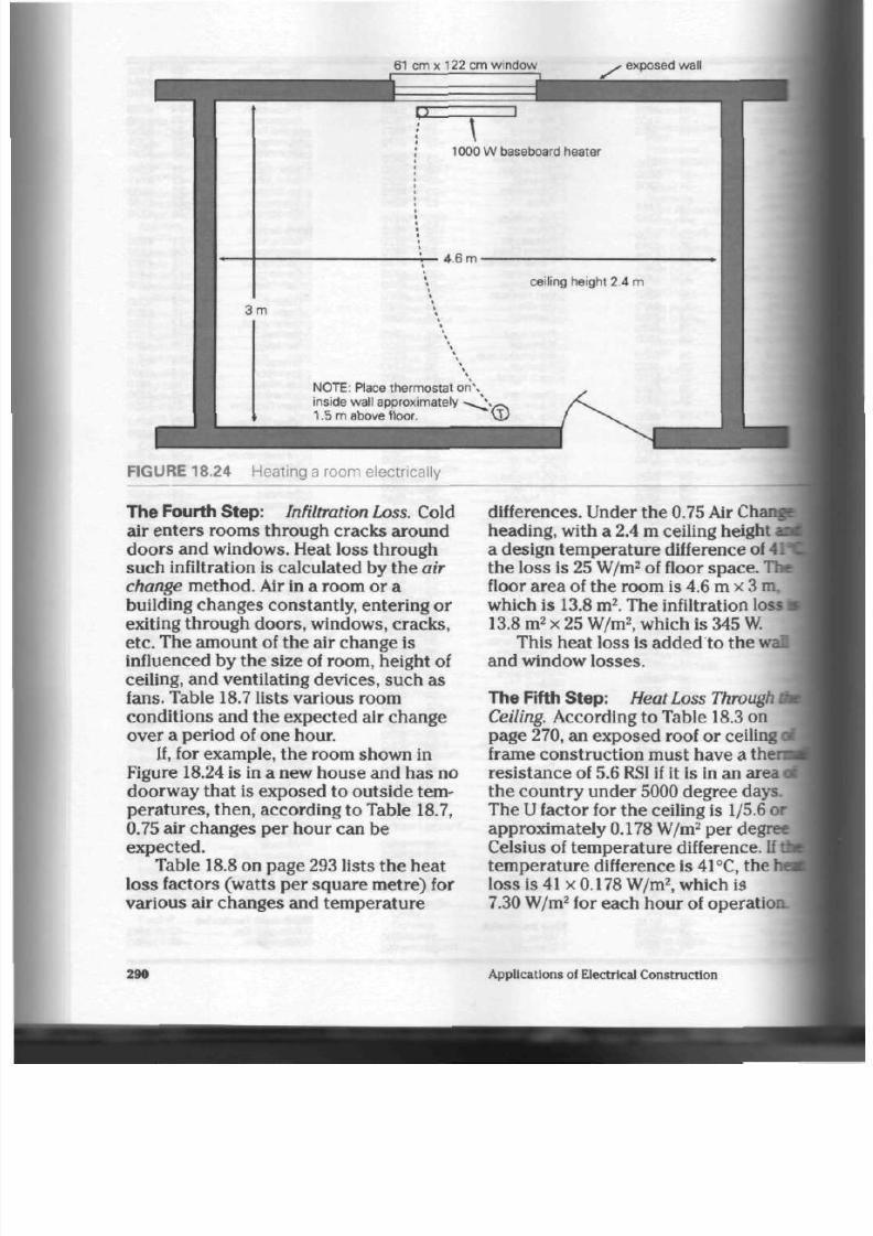
8/19/2019 Applications Electrical
http://slidepdf.com/reader/full/applications-electrical 295/447
61 cm x 122 cm window
rx
3 m
1000 W baseboard
heater
4.6 m-
ceiling height 2.4
m
N O T E :
Place thermostat
o n \
inside wal l approximately - s i y ^
1.5 m
above floor.
Cl)
-I *•
FIGURE 18.24 Heating a room electrically
The Fourth Step:
Infiltration Loss. Cold
air enters rooms through cracks around
doo rs and windows. Heat loss throu gh
such infiltration
is
calculated by th e air
change m etho d. Air in
a
room
or a
building changes constantly, entering
or
exiting throug h doo rs, windows, cracks,
etc.
The amount
of
the air change
is
influenced by the size of room, h eight of
ceiling, and ventilating devices, such as
fans.
Table 18.7 lists var ious room
conditions and the expected air change
over a period of one hour.
If, for example, the room shown in
Figure 18.24 is in a new house and h as no
doorway that is exposed
to
outside tem
peratures, then, according to Table 18.7,
0.75 air cha nge s per hour can be
expected.
Table 18.8 on pag e 293 lists th e hea t
loss factors (watts per square metre) for
various air changes and temp erature
differences. Under the 0.75 Air Change
heading, with a 2.4 m ceiling height i
a design temperature difference of 4V
the loss is 25 W/m
2
of floor sp ac e. The
floor area
of
th e room is 4.6 m
x
3 m,
which
is
13.8
m
2
.
The infiltration loss
a
13.8 m
2
x 25 W /m
2
, which is 345 W.
This heat loss
is
added
to
t he wai]
and window losses.
The Fifth Step:
Heat Loss Through d
Ceiling.
According
to
Tab le 18.3 on
page 270, an exposed roof or ceiling <
frame constru ction mu st have a the
resistance of 5.6
RSI
if it is in an area
ot
the cou ntry unde r 5000 degree days.
The
U
factor
for
the ceiling is 1/5.6 or
approximately 0.178 W /m
2
per degree
Celsius
of
tem pera ture difference. If tfcj
tem pe rat ure difference is 41°C, the
ha
loss is 41 x 0.178 W /m
2
, which is
7.30 W /m
2
for each hour of op eration.
290
Applications
of
Electrical Construction

8/19/2019 Applications Electrical
http://slidepdf.com/reader/full/applications-electrical 296/447
TABLE 18.6 Heat Loss Factors for W indo ws and Doors
Heat load Factor per Degre e o f Tem peratu re D i f ference
W i n d o w s a n d D o o r s
Single glass—metal frame
Single glass—metal frame with storm
Double glass—metal frame (6 mm air space)
Double glass—metal frame (13 m m air space)
Triple
glass—metal
frame
(13
mm air space) + storm
Single glass—wood frame
Single glass—wood frame with storm
Double glass—wood frame (6 mm air space)
Double glass—wood frame (13 mm air space)
Triple glass—wood frame (13 mm air space) + storm
Skylight—metal frame—single glass
Skylight—metal frame—double glass (6 mm air space)
Skylight—wood frame—single glass
Skylight—wood frame—double glass (6 mm air space)
Doors
Patio
Doors—single glass—metal
frame
Patio Doors—double glass—wood frame
Solid wood—40 m m
Solid wood—40 mm (wood storm)
Solid wood—40 mm (metal storm)
Metal (Flat)
Metal (Corrugated)
Rt
0.16
0.32
0.23
0.25
0.41
0.17
0.35
0.28
0.30
0.52
0.14
0.21
0.16
0.27
0.16
0.20
0.36
0.65
0.53
0.16
0.13
W/m
2o
C
6.25
3.18
4.43
3.97
2.44
5.79
2.90
3.52
3.29
1.93
6.93
4.77
6.25
3.75
6.42
4.94
2.78
1.53
1.87
6.42
7.95
" : -neans
resistance total in RSI values.
The ceiling area of th e room shown
in Figure 18.24 is 13.8 m
2
. This is th e area
through which heat can p ass . The tota l
heat loss for the room over a pe riod of
one hour is 13.8 m
2
x 7.30 W/m
2
, which is
approximately 100.7 W.
The Sixth Step : Total
H eat Loss for the
Room. To calculate the total heat loss
for the roo m over a pe riod of on e hour,
the loss through eac h of the four a reas
must be added.
For example:
Heat Loss
Through the wall
Through the window
Infiltration
loss
Through the ceiling
Total
144.2 W
86.0 W
345.0
W
100.7 W
675.9 W
Determining Heater Size
Winter weather can be unpredictable
and h ave little in com mo n with carefully
recorded norm s. Care should be taken to
match the actual heater size (wattage)
with the calculated heat loss for the
room or area .
The sam ple room sh own in Figure
18.24 ha s a calc ulated hea t loss of
675.9 W. Table 18.9 lists low- and stan d
ard-watt density baseboard heater units
The closest heater unit in the standard-
watt density column to our calculated
heat loss is the 750
W
one. Our cho sen
hea ter unit has approximately
75 W
of
extr a heating ability: it can therefo re
provid e a margin of com fort if there is a
winter season that is colder than nor
mal. Care must be taken not to oversize
Residential Electric Heating
29
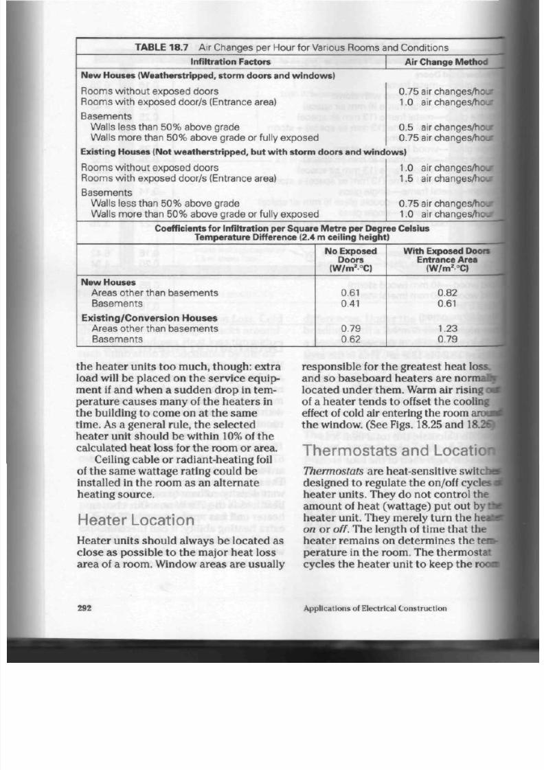
8/19/2019 Applications Electrical
http://slidepdf.com/reader/full/applications-electrical 297/447
TABLE 18.7 A i r C hanges per H our f or Var ious R oom s a
Infiltration Factors
New Houses (Weatherstripped, storm doors and win dow s)
R o o m s w i t h o u t e x p o s e d d o o r s
R ooms w i t h ex pos ed door /s (E nt ranc e area)
B a s e m e n t s
W al ls les s t han 50% abov e grade
W al ls more t han 50% abov e grade or f u l l y ex pos ed
nd Condi t ions
Air Change Method
0.75 air
changes/hour
1.0 air
changes/hour
0.5 air
changes/hour
0.75 ai r changes/hour
Existing Houses (Not weatherstripped, but wi th storm doors and window s)
R o o m s w i t h o u t e x p o s e d d o o r s
R ooms w i t h ex pos ed door /s (E nt ranc e area)
B a s e m e n t s
W al ls les s t han 50% abov e grade
W al ls more t han 50% abov e grade or f u l l y ex pos ed
1.0 a ir
changes/hour
]
1.5
air changes/hour
j
0.75 ai r
changes/hour
]
1.0 a ir change s/hour
Coefficients
for
Infiltration per Square Me tre per Degree Celsius
Tempe rature Difference (2.4 m ceiling height
New Houses
A r e a s o t h e r th a n b a s e m e n t s
B a s e m e n t s
Ex is t ing /C onvers ion H ouses
A r e a s o t h e r t h a n b a s e m e n t s
B a s e m e n t s
No Exposed
Doors
(W/m
2o
C)
0.61
0.41
0.79
0.62
Wi th Exposed Doors
Entrance Area
(W/m
2o
C)
0.82
0.61
1.23
0.79
the heater units too much, though: extra
load will be placed on th e service e quip
ment if and w hen a sudd en d rop in tem
perature causes many of the heaters in
the bu ilding to come on at the sam e
time.
As a general rule, the selected
hea ter unit shou ld be within
10%
of the
calculated h eat loss for the room or a rea.
Ceiling cable or radian t-hea ting foil
of the sam e wattage rating could be
installed in the room as an alternate
heating source.
Heater Location
Heater units should always be located as
close as possible to the m ajor h eat loss
area of a room . Window areas a re usually
respo nsible for the greatest h eat
loss,
and so basebo ard he aters are
nor mal
located under them. Warm air rising a
of a he ate r te nd s to offset the cooling
effect of cold air entering th e room
th e w indow. (See Figs. 18.25 and 18.2
Thermostats and LocatioW
Thermostats are heat-sensitive switcha
designed to regulate the on/off cycles i
hea ter un its. They do not co ntrol the
amo unt of heat (wattage) p ut out by
I
hea ter unit. They m erely turn the h«
on
o r
off.
The length of tim e that the
heater rem ains on determines the tem
peratu re in the room . The therm ostat
cycles the hea ter unit to keep the roofl
292
Applications
of
Electrical Construction

8/19/2019 Applications Electrical
http://slidepdf.com/reader/full/applications-electrical 298/447
TABLE 18.8 H eat L os s Fac t ors per Square Me t re F loor A rea and A i r C hange Values
(Inf i l t rat ion)
V alues for V arious Temperature
Differences
0. 5 A i r Change
0.75
A i r Change
1.0
Air C h a n g e
1.5
A i r C hange
Ceiling
Height
(m)
2.4
2.7
3.0
2.4
2.7
3.0
2.4
2.7
3.0
2.4
2.7
3.0
Heat Loss Factors P er Square M etre
(W/m
2
)
1°C
0.41
0.47
0.50
0.62
0.70
0.78
0.81
0. 93
1.0
1.2
1.4
1.5
38°C
15
18
19
24
27
29
31
35
39
46
52
58
41 °C
17
19
21
25
29
32
33
38
42
50
56
63
44°C
18
20
22
27
31
34
36
41
45
54
61
67
47°C
19
22
24
29
33
36
38
44
48
57
65
72
50°C
20
23
25
31
35
39
41
4 7
51
61
69
77
53°C
22
25
27
33
37
41
43
4 9
54
65
73
81
56°C
23
26
28
35
39
43
46
52
58
68
77
86
TABLE 18.9 L ow - and S t andard- W at t D ens i t y H eat er
Specifications
Specifications: Single P hase: Low -W att Density
Volts
(specify)
120 208 240
120 208 240
120 208 240
120 208 240
208 240
Watts
500
750
1000
1250
1500
Approximate
Length
(cm)
96
127
188
250
250
Approximate
Shipping Mass
(kg)
6
7
10
13
13
Specifications: Single Phase: Stan dard- Wa tt Density
120 208 240
120
2 0 8 2 4 0
120 208 240
120 208 240
120 208 240
2 0 8 2 4 0
208 2 4 0
208 240
500
750
1000
1250
1500
1 7 5 0
2 0 0 0
2250
66
96
127
188
188
250
250
250
4
6
7
10
10
13
13
13
Residential Electric Heating
293

8/19/2019 Applications Electrical
http://slidepdf.com/reader/full/applications-electrical 299/447
FIGURE 18.25
installation
A residential baseboard
.e
i
c
O
&
O
FIGURE 18.26
installation
A baseboard heater corridor
at the tempera ture selected on th e
thermostat .
For many yea rs, conventional ther
mostats had basic mercury bulbs for
their sw itch co nta cts. The advent of cen
tral air conditioners meant that thermo
stats had to becom e more sophisti
cated—they had to be ab le to con trol
both heating and cooling cycles. Now
there are therm ostats that can sense
tem peratures accurately through elec
tronic circuitry.
An
electronic
thermostat smoo thes
out th e cycling proce ss of the hea ter
unit, providing a more con sistent
and
even temperature throughout the
rooa
As a result, th e
home-owner
can
oftea
choo se a lower therm ostat setting,
resulting in lower heating c os ts over a
perio d of time.
The rmo stats, as mentioned
earlieq
are highly tem per atur e sensitive and
should not be mounted on cold,
oi
walls. They should be located on
in
walls,
away from any draft or heat
source that might cause them to
op
and close the h eater circuit in an
i
mal
manner. They can be obtained
ii
both line and low voltage configura
to m atch th e type of heating system
use d. Figure 18.27 sho w s s evera l
of thermostat controls.
Tem perature regulation can be
I
died
differently in foyers and
entra
halls,
which are often s ubjec t to cold
blasts of air from door openings. If a
forced air unit
is installed in the wall
i
th e entra nc e, the effect of cold blasts
can b e counte racted . Cold air enter
the area will activate the
thermostat <
th e heater. The fan th en forces enc
warm air through the heater to
retur
the are a to inside design
temperati
Such a com pac t un it can also sc
times be used to adv antag e in
bath
rooms with limited wall space at
floo
level.
A forced air unit cons ists of a i
enclosure or tub with a detachable I
and heater unit. A grille placed over I
unit directs the air flow and protects I
heater coils. (See Figs 18.28 and 18.2
Heating Cost
Once the heat loss (heating load) has
been calculated for each area, the i
heat load
figure can be worked out.'
total hea t load is th e sum of the heat
losses calculated for each area. An
294
Applications of Electrical Construction

8/19/2019 Applications Electrical
http://slidepdf.com/reader/full/applications-electrical 300/447
Low
voltage
thermostat
Line voltage thermostat
fan and heater unit
(fits
into
tub)
grillwork
(directs heated air
and protects heater element)
FIG URE 18.28 Forced air heater uni t
exam ple for calculating heatin g cos ts fol-
1 lows. It is based on estimated heat
| lo sse s (in roun d figures) for a five-room
I bunga low in Toro nto or a similar area.
Heating and co oling therm ostat
F I G U R E 1 8 .2 7 C o m m o n l y u s e d
t h e r m o s t a t s
c
o
I
1
8
Heated Area
Bedroom
#1:
Bedroom #2:
Kitchen:
Living and dining room :
Bathroom:
Basement:
Heat Loss
1000
w
1000 w
1000
w
2500 W
500 W
3000 W
9000 W
or9kW
Residential Electric Heating
295

8/19/2019 Applications Electrical
http://slidepdf.com/reader/full/applications-electrical 301/447
FIGURE 18.29 Forced air heater unit applications (near cold air entry and where wall
limited)
296
Applications of Electrical Construction
8/19/2019 Applications Electrical
http://slidepdf.com/reader/full/applications-electrical 302/447
Total heat load:
Annual kilowatt hour consumption •
HL x DD x C
DTD
Where:
HL
=
hea t loss in kilowatts
DD = annual deg ree days for the area
(See Table 18.5)
C
=
a consta nt (15.3 for the T oron to
area; consult local utility)
DTD = design tem pera ture difference
between indoors and ou tdoo rs
Therefore, kilowatt hour consumption is
9 x 4082 x 15.3
40
= 14 052kWh
Typical utility cha rges ar e as follows:
First 500 kW p er m onth
@ 7.9«/kW-h
Remaining kilowatt h ou rs
@
5.5<t/kW
h (end rate)
Electrical heating customers
approach the end rate with lighting and
cooking energy. The annu al heating cost,
therefore, is calculated by m ultiplying
the kilowatt hou r consum ption by t he
end rate.
Total annua l co st:
14052 kWhx5.5«/kW h = $772.86
Overheating Protection
Baseboard heaters are equipped with a
slender, liquid-filled or vapour-filled cop
per tube that trave ls the length of th e
heater. If for som e reaso n th e he ate r
reaches an abnormally high temp era
ture, the expa nding liquid or vap ou r will
cause a relay at one end of the tub e to
open th e circuit. This preven ts heat
damag e to the walls of the h om e. (See
Fig. 18.30)
Snow Melt ing Heaters
One type of radiant-h eating c able is
designed for use in drivewa ys to keep
th e wheel track areas clear of snow. It is
installed under the concrete pavement
and com es in
pre-assembled
lengths
from th e manufacturer. It is also used to
melt snow on ram ps and stairways . (See
Figs.
18.31 and 18.32)
Snow that has melted, run into
eaves, and refrozen also causes prob
lems. Eavestrough he aters are used to
keep th is pa rt of the roof clear. (See
Fig. 18.33)
Pipes can be kept from freezing by
wrapping them with pipe-heating cable.
A the rm os tat that fits along the side of
the pipe controls the heating p roce ss.
(See Fig. 18.34)
Residential Electric Heating
29

8/19/2019 Applications Electrical
http://slidepdf.com/reader/full/applications-electrical 303/447
heat-radiat ing f ins
copper vapour t u n *
thermostat
heater element
FIGURE 18.30 S ection of
a
baseboard heater electrical con nection
FIGURE 18.31 Driveway sno w-m elting cable
298
Applications of Electrical Construction
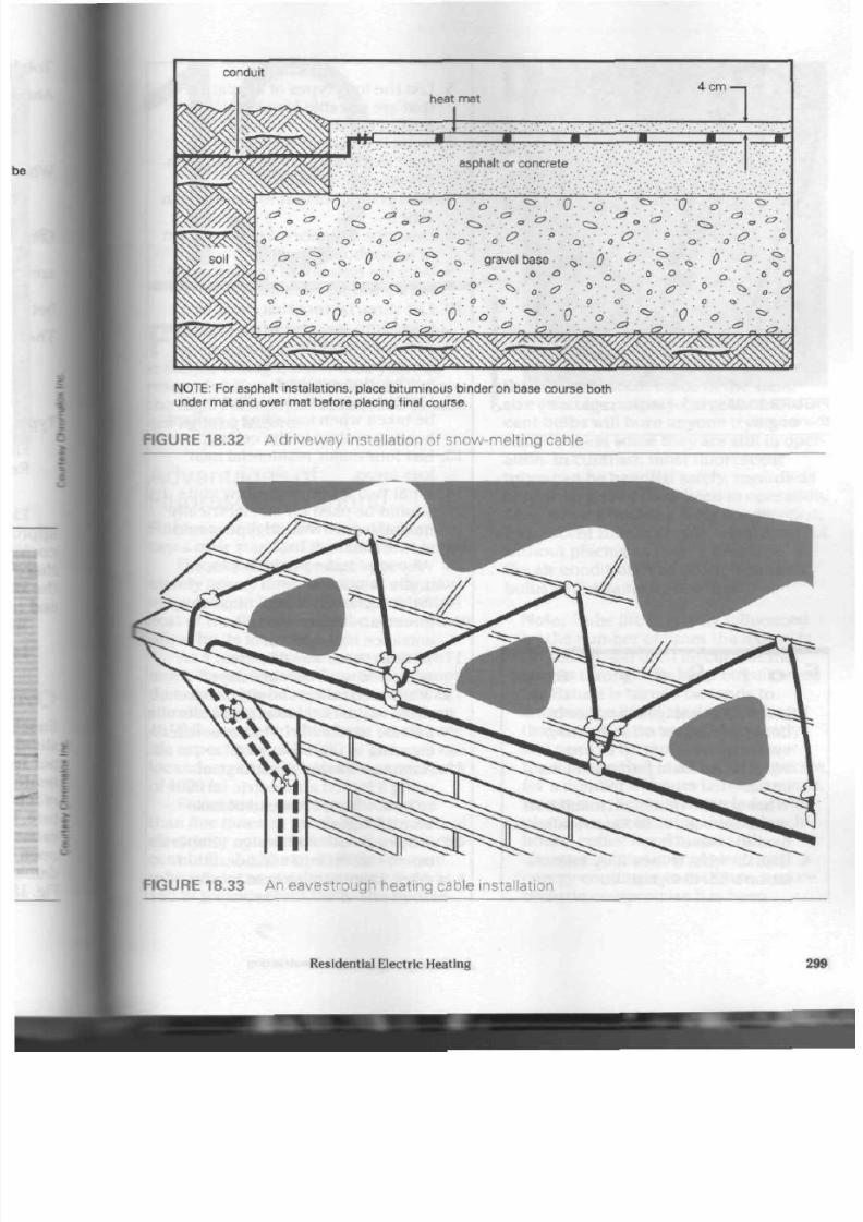
8/19/2019 Applications Electrical
http://slidepdf.com/reader/full/applications-electrical 304/447
conduit
heat mat
4 cm
1
asphalt or concrete
.•or.
'• .*.
0
.d.
•- . ^ . . ' 0 - . o '••
• . a •
a
• • . .c
•
•„ . . . .0
o
.
O:
O
o:
« O
. » • • •
C i .
•
o-. 0
<£?•.
• • . * " • • . * ? • • • ?
• ' • b - : .
9ravel base
0
. ; 0 - . ^ • ? • ' .*. ' ; 0 '• \ <b •. .«>.
N O T E :
For asphalt installations, place bituminous binder on base course both
under mat and over mat before placing final course.
FIGURE 18.32 A driveway installation of snow -me lting cable
FIGURE 18.33 A n eavestrough heating cable installation
Residential Electric Heating
29
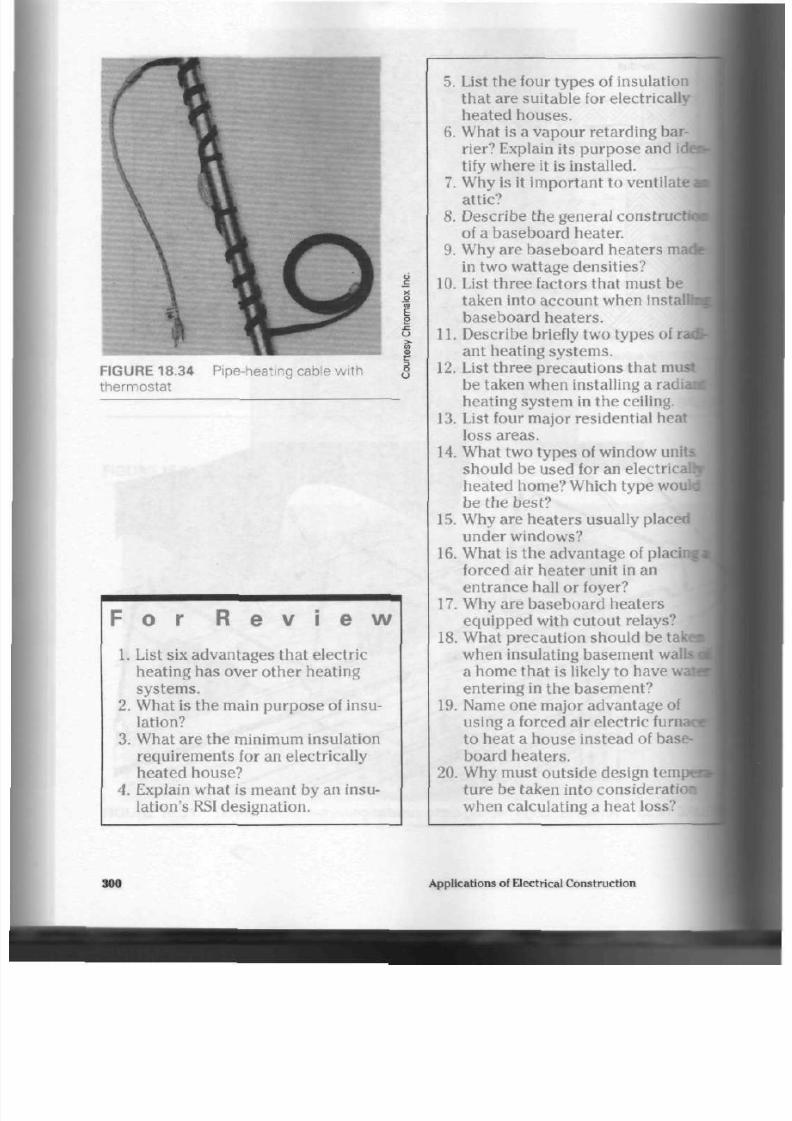
8/19/2019 Applications Electrical
http://slidepdf.com/reader/full/applications-electrical 305/447
FIGURE 18.34
thermostat
P ipe-heating cable wi th
F o r R e v
i
e w
1. List six advantages that electric
heating has over othe r heating
systems.
2. What is the main purpose of insu
lation?
3.
What are the minimum insulation
requirements for an electrically
heated house?
4. Explain what is meant by an insu
lation's RSI designation.
5. List the four types of insulation
tha t are su itable for electrically
heated houses.
6. What is a vapou r retard ing bar
rier? Explain its pu rpo se and
idea
tify w here it is installed .
7. Why is it imp ortan t to ventilate
m
attic?
8. Describe the general constructing
of a baseboard heater.
9. Why are baseboa rd heate rs made
in two wattage densities?
10. List three factors that must be
taken into account when installu^
baseboard heaters.
11. Describe briefly two typ es of
rati
ant heating systems.
12.
List three precautions that must
be taken w hen installing a
radiad
heating sy stem in the ceiling.
13. List four major residential heat I
loss areas.
14.
What tw o types of window
uni t s
should be used for an electrical^
heated home? Which type woukl
be the best?
15. Why are heaters usually placed
under windows?
16.
What is the a dva ntage of
pla
forced air heater unit in an
entrance hall or foyer?
17.
Why are base board heate rs
equipped with cutout relays?
18. What precaution should be t
when insulating basement w;
a hom e that is likely to hav e
entering in the basement?
19. Name one m ajor adv antag e of
using a forced air electric fur
to heat a house instead of
bas
board heaters.
20. Why must ou tside design tern;
ture be taken into consideratl
when calculating a heat loss?
\
300 Applications of Electrical C onstruction

8/19/2019 Applications Electrical
http://slidepdf.com/reader/full/applications-electrical 306/447
F
luores cent lighting was first devel
oped during the 1930s. Its principle
is simple enough, b ut it took ye ars of
research before it was deve loped into
the highly developed tub e found in mod
ern lighting fixtures.
Advantages of
Fluorescent Lighting
Fluorescent lights have m any advan
tages over standard incandescent lamps.
Fluorescent lamps last approxi
mately
twenty times
as long as stan dard
incandesc ent lamps. The higher initial
cost of the fluorescent tube is more than
offset by it s long life.
As a result,
maintenance costs
are
much lower, bec aus e fluorescent lamps
do not need to be replaced as often as
standard incandescent lamps. Modern
40
W
fluorescent tu bes hav e an average
life exp ecta ncy of 20 000 h. The avera ge
incandesc ent bulb has a life exp ectancy
of 1000 h.
Fluorescent tubes p roduce more
than
five times
as m uch light per watt of
electricity consumed than the incandes
cent bulb . A 120 cm, 40
W
fluorescent
tube p rodu ces nearly as m uch light as a
150 W
incande scent bulb. The fluores-
Discharge
Light
Sources
cent tu be also keeps its brightoess for a
longer period of time.
Fluorescent tub es produ ce less hea
than incandescent bulbs of the same
size (wattage outp ut). Large incandes
cent bulbs will burn anyone trying to
remove them while they are still in oper
ation. In co ntra st, m ost fluorescent
tubes can be handled safely, regardless
of how long they have be en in o peration
Also, wh en a building is air cond itioned
fluorescent tubes provide adequate ligh
without placing as large a heat load on
the air conditioner as do incandescent
bulbs of the same light output.
Note: Tube life is greatly influenced
by the number of times the fixture is
turned on and off. The current that
surges throu gh th e lamp circuit when
the fixture is turned on tend s to
sho rten th e life of the lam p.
A
lamp
tha t is turn ed on and off frequently
will need to be replaced far sooner
than a lamp that is allowed to ope rate
for a num ber of hours betw een sta rts
As a result, lights in many indu strial
plants are left burning during lunch
ho urs , coffee break s, and shift
cha nge s. As the cost of electrical
energy continues to increase, a more
realistic compromise has been
Discharge Light Sources
3
8/19/2019 Applications Electrical
http://slidepdf.com/reader/full/applications-electrical 307/447
reache d b etween tu be life and energy
cos ts. It is now considered more eco
nomical to turn th e lamps off when th e
off period is expected to be more than
20 min in duration.
Disadvantages of
Fluorescent Lighting
In some places, such as clothing, fabric,
and meat stores,
colour
is critical and
the de sign of the lighting system impor
tan t. Fluorescen t lights give off an abun
dan ce of blue and green ton es, but are
low in red s and yellows. The ir us e in, for
example, a clothing or m eat sto re, would
preven t a custom er from seeing the true
colour of the product. Walking outside to
natural light is not always practical, and
so in these cases both incandescent and
fluorescent lights are used to help bring
out true colours. However, fluorescent
tub es for "colour critical" areas have
now been developed.
Using discharge lamps over rotating
machinery can sometimes be danger
ous . The 60
Hz AC
supply system of fluo
rescent fixtures makes the light flicker at
a very high speed. This flickering is
almost invisible to the naked eye, except
whe n t he light falls directly on ro tating
m achine ry. If th e m achin e is rotating at a
speed close to the speed at which the
light is flickering, th e m ach ine will
app ear to b e standing still. This strobo-
scopic effect deceives the human eye.
The re have been cases where an opera
tor has absent-mindedly reached in to
touch a rotating part, thinking that the
mach ine has com e to a standstill.
Fortunately, this problem can be
remedied by installing a small incandes
cent lamp over the moving part or
assembly. This filament type of lamp will
cancel out any strobe effect produced by
the fluorescent tube fixture.
Fluorescent Tube Parts
T he he art of th e fluorescent fixture
t
the tube
itself.
The tub e ha s several
components . (See Fig. 19.1)
Glass Tube. The tub e provides an
airtight enclosure in which the
mer
gas, and pho sph or can function.
Base. As the end of the tube , the
bai
con nec ts the lamp to the electrical
circuit. Several pin configurations are
available.
Ca thod e. Th ese small, oxide-coated
filaments heat up and emit electrons
•
to the tube.
Mercury. Drop lets of m ercu ry are
placed in the tub e. They vapourize
during the o peration of the lamp and
emit (give off) ultrav iolet energy.
Filling Gas.
A
small am oun t of high
purified argo n gas is also placed in tbi
tube. This gas ionizes (producing
electrical conductivity in gases) wha
sufficient voltage is applied. Current i
then flow readily through the tube.
Ph osp ho r Co ating . All of th e light
energy produ ced by the m ercury is
ultraviolet and invisible to the naked
eye. The pho sph or coating reacts to I
ultraviolet rays and turns this energy
into visible light.
The Starter
Some fluorescent fixtures (preheat
i
need a small starting mechanism to
establish an electron emission from
I
cathode (filament). (See Fig. 19.2)
Current enters the starter through
one of the contact pins. T he neon gas a
302
Applications of Electrical Construction
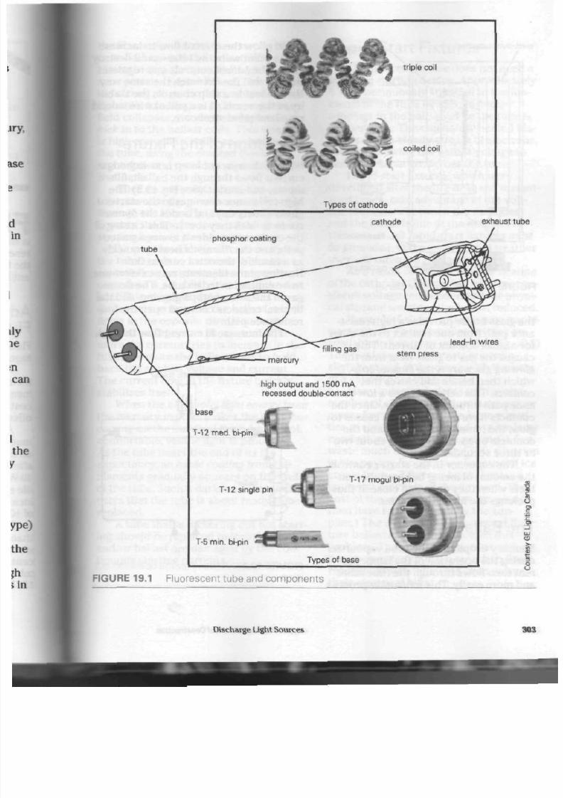
8/19/2019 Applications Electrical
http://slidepdf.com/reader/full/applications-electrical 308/447
triple coil
£ &
? J ^ coiled coil
Types of cathode
cathode
exhaust tube
phosphor coating
lead-in wires
stem press
high output and
1500 mA
recessed
double-contact
base
T-12
med.
bi-pin
T-12 single pin
T-17
mogu l bi-pin
T -5 min. bi-pin
Types of base
FIGURE 19.1 Fluorescent tube and com pone nts
8
v
Discharge Light Sources
303

8/19/2019 Applications Electrical
http://slidepdf.com/reader/full/applications-electrical 309/447
electrolytic capacitor
glass tube
aluminum can
contacts
bimetal strip
neon gas
insulating
sleeve
fibre base
contact
pin
F I G U R E
19.2
F l u o r e s c e n t s t a r t e r
the glass bottle provides a high-resist
ance path from one conta ct
to
the other
for a small amo unt of curre nt. T his
cause s the gas to glow. Heat from the
glowing gas warms the bimetal strip,
which then bends and closes the
contacts.
This action cre ates
a
low-resist
ance path through the
starter.
Once the
contac ts have closed, the gas ceases
to
glow, th e bim etal strip co ols, and the
con tacts open . All this takes abo ut tw o
or three seco nds.
The capacitor in the st art er contro ls
the amount of arcing between th e con
tacts when they open and close. It thus
prolongs the life
of
the starter.
The Ballast
Mercury droplets in the tube vapourize
during th e oper ation of the lamp. Cur
rent then flows through the tub e m ore
and m ore easily. This ionization process
could allow the current flow to incr
to the p oint were the tub e would d«
itself. The ballast controls and regulal
this cu rren t flow in much th e same
*w\
that ballast
in a
ship con trols the staU
ity
of
the ves sel. It is
a
coil
of
wire wc
on a laminated steel core.
Operation
of
the Fixture
When a fluorescent lamp is switche
current flows through the ballast,
ments, and starter. (See Fig. 19.3) Th
high-resistance neon gas in th e starta
glows (heats up) and bends the bimtM
contacts until they touc h. This closh^B
the c ontacts provides
a
low-resista
path, and the filaments heat up quickl
as
a
result
of
the extra current flow.
Heating
of
the filaments ca use s elec
to be emitted in to the tu be. The neon
gas in the sta rter stop s glowing, and
bimetal contacts cool and open the I
resistance path.
Th e increa se in cu rren t flow throi
automatic starter
w
ballast
1
f
FIGURE 19.3
A
circuit
for
the operation
lamp
304
Applications of Electrical Construction
8/19/2019 Applications Electrical
http://slidepdf.com/reader/full/applications-electrical 310/447
the filaments also caus es a stron g
mag
netic field around the ballast. When the
bimetal contacts open, the high-resist
ance path is re-established. This ca uses
the strong magnetic field a rou nd the bal
last coils to co llapse. As the mag netic
field collapses, it induces a high-voltage
kick
in to the ballast coils. This voltage
is high enough t o strike an arc acr oss
the tube, using the emitted electrons,
argon gas, and m ercury vapo ur as a cur
rent path.
Once an arc is established acro ss the
tube, m ost of the circuit current flows
through the tub e. Not enough curre nt
flows to the starter to re-establish a
starting cycle in the neo n gas.
As men tioned before, curren t flow in
the tube tend s to increase. When t he
current flow increases, a stronger mag
netic field is estab lished aroun d th e bal
last. This magn etic field pro du ces
(induces) a voltage in the ballast, which
flows in th e opposite direction to the
applied voltage from t he so urc e. The
more the current tries to increase in the
tube,
the more the ballast tries to hold
back the applied voltage and current.
The current flow in the fixture quickly
stabilizes
itself.
When the ultraviolet light energy from
the mercury vapour strikes the phosphor
coating
on th e inside of the tu be , a cool,
comfortable, visible light is pro duc ed.
As the tu be n ears the end of its life
expectancy, an
oxide coating
from the
filaments gradually ap pe ars on th e en ds
of the tub e. Such a dark ened area indi
cates that the tu be is abou t ready to be
replaced.
A
tube th at is flickering bu t not star t
ing should be replaced before the star ter
and/o r ballast are damaged by the con
tinuous starting currents.
Rapid-Start Fixtures
This fluorescent fixture does
not
need a
sep arate starting device. Approximately
4 V is continu ously supplied to th e fila
me nts of the tub e by special heater
windings in the ballast while th e tub e is
in operation. The constantly heated fila
me nts emit a steady stream of electrons
thereby allowing the ballast voltage to
easily strike an arc acro ss th e tub e.
Rapid-start fixtures, which w ere
developed after the pre-heat and instan
start types, take advantage of the volt
age that exists between the cathodes
and the metal frame of the fixture. For
this reason,
all
rapid -start fixtures
mus
be grounded. Otherwise, in cool wea the
the y will often fail to st ar t.
As a result of th e con tinuo us heating
of th e ca tho de s (filaments), a lower open
circuit voltage can be used and t he ph ysi
cal size and weight of th e ballast red uce d
Figure 19.4 shows a single-tube, rapi
star t circuit. The se po pular fixtures are
availab le in two-lamp u nit s. (See Fig. 19.5
The two-lamp fixture st ar ts one tu be
slightly ahead of the other, with the help
of a capacitor in the ballast.
Many industrial plants with a large
number of electrical motors have a poo
power
factor.
They receive large quanti
ties of electrical ene rgy and require larg
conductors and control equipment, but
waste much of the power. (This situatio
is like paying for only two flavours of ic
cream from a 3-flavour brick, because
you w ant only two of the flavours. The
cos t of the wasted third flavour would
then have to be covered by the sup
plier.) The capacitor in fluorescent fix
ture b allasts helps to overcome th is
problem. That is why industries with a
poor power factor often switch to fluo
rescent fixtures. They can then reduce
their electrical bills.
Discharge Light Sou rces
3

8/19/2019 Applications Electrical
http://slidepdf.com/reader/full/applications-electrical 311/447
da
•JLSAZJLA
heater extension
winding winding
:
iS-B-MJ
primary
line
w i n d i n g
line
winding
heater
FIGURE 19.4 A single-tube, rapid-start cir
cuit. (The rapid-start b allast supplies a sm all
amo unt of voltage co ntinuously to the
cathodes.)
lamp
£
series
start
capacitor
" /
H(
heater
winding
=3
J
lamp
yellow
' leads
— |
TBfwi
pnnrp-
power factor |_l 1
capacitor
blue leads
—*i
- heater
winding
ballast
FIGURE 19.5 A 2 lamp rapid-start circuit
Ballast O verheating
In the pro cess of limiting tub e cu rren ts
and p roviding starting voltages, th e bal
last tend s to warm up. As a ballast ages,
the laminated steel core of the tran s
former often loo sens, vib rates (produ c
ing a humming sound ), and pen etrates
the insulation on th e windings. At times,
this will sh or t circuit som e of th e wind
ings, cau sing an e xce ss cu rren t flow in
th e remaining windings. As a result of
this breakd ow n in insulation, a damag
ing amount of heat is produced in the
ballast. Today, manufacturers are
eqi
ping ballasts w ith a
therm al protector
(cutout) to open th e ballast circuit
ai
matically when the heat reaches a dan
gerous level.
Ambient temperature ( the temper*-]
ture of the surrounding air) also playsi
im po rtan t role in th e life span of the
I
last. Figure 19.6 shows the life expect
ancy of a ballast und er various t em |
ture con dition s. Figure 19.7 shows a
rapid-start ballast and its constructed
Th e Canadian Electrical cod e
requ ires that all fixtures m ounted on
<
combustible surface be equipped wi
thermally protected ballast. Ballasts aie
rated by the m anufacturer to operate a
tem pera tures up to 90°C.
Instant-Start
Fixtures
The tubes for this fixture are
generalh
th e single-pin type and cannot be
,
110°C
100°C
life vs. temperature
lost
life
lost
•
90°C
0
FIGURE 19.6 L ife versus tempe rature
generally accepted "lost l ife rule" is
every 10°C increase in tem perature,
life is cut in half." |
306
Applications of Electrical Construction

8/19/2019 Applications Electrical
http://slidepdf.com/reader/full/applications-electrical 312/447
FIGURE 19.7 Rapid-start ballast
Discharge Ught Sources
307
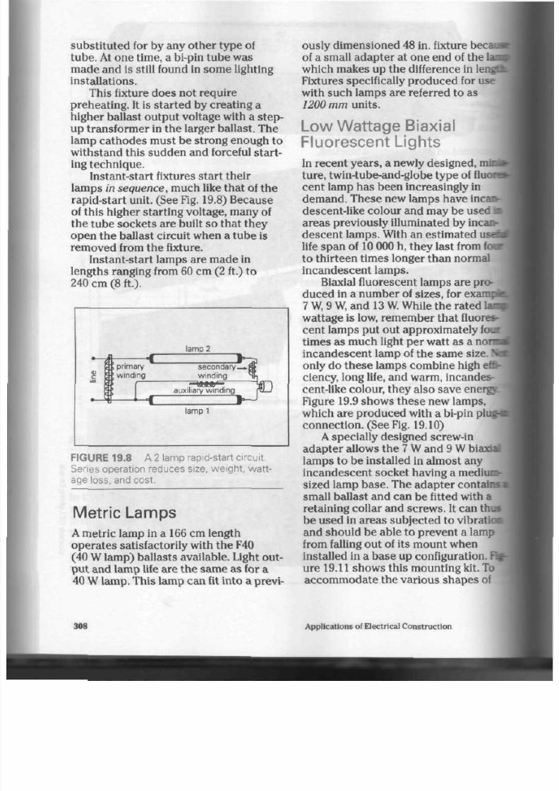
8/19/2019 Applications Electrical
http://slidepdf.com/reader/full/applications-electrical 313/447
substituted for by any other type of
tub e. At on e time, a bi-pin tub e was
m ade an d is still found in som e lighting
installations.
This fixture does not require
preheating. It is started by creating a
higher ballast output voltage with a
s tep-
up transformer in the larger ballast. The
lamp cathodes must be strong enough to
withstand this sudden and forceful start
ing techniq ue.
Instant-start fixtures start their
lamps
in sequence,
much like that of the
rapid-start unit. (See Fig. 19.8) Because
of this higher starting voltage, many of
the tub e sockets are built so that th ey
open the ballast circuit when a tube is
removed from the fixture.
Instant-start lamps are ma de in
lengths ranging from 60 cm (2 ft.) to
240 cm (8 ft.).
I
\
E
r C "
Lb ™
primary
winding
lamp
2
U*a
econdary—.8>
winding N^
auxiliary win ding ra_/
lamp 1
FIGURE 19.8 A 2 lamp rapid-start circuit.
Series operation reduces size, weight, watt
age loss, and cost.
Metric Lamps
A
m etric lam p in a 166 cm length
operates satisfactorily with the F40
(40 W lamp) ba llasts ava ilable. Light out
pu t and lam p life are the sam e as for a
40 W
lam p. This lamp can fit into a previ-
308
ously
dim ension ed 48 in. fixture
becaad
of a small ad ap ter at one end of the
lai^
which m akes up the difference in lengn
Fixtures specifically produced for use
with such lamps are referred to as
1200 m m units.
L ow W attage Biaxial
Fluorescent Lights
In recent ye ars, a newly designed, mini
ture,
twin-tube-and-globe typ e of fluosB
cent lamp has been increasingly in
deman d. These new lamps have
inca*-
descent-like
colour and m ay be used
•
areas previously illuminated by incan- I
des cen t lam ps. With an estimate d usdU
life span of 10 000 h, they last from
fow
to thirteen times longer than normal
incandescent lamps.
Biaxial fluorescent lamps are pro
duce d in a num ber of sizes, for
exampii
7
W,
9
W,
and 13
W.
While the ra ted Ian
wa ttage is low, rem em ber tha t fluores
cent lamps put out approximately four
times as much light per watt as a
normt
incand escent lamp of the same size.
N ^
only do th es e lam ps co m bine high effi
ciency, long life, and warm, incandes
cent-like colour, they also save energy:
Figure 19.9 sho ws t he se new lamps,
which are produced with a bi-pin pi
conn ect ion . (See Fig. 19.10)
A specially designed screw-in
adapter allows the 7 W and 9 W biaxial |
lamps to be installed in almost any
incan desce nt sock et having a medium-
sized lamp ba se. The adapt er contain*
small ballast an d can be fitted with a
retaining collar and scre ws . It can thu s
be used in areas subjected to
vibratk»
and should be able to prevent a lamp
from falling out of its mount when
installed in a base up configuration. Fig
ure 19.11 shows this mounting kit. To
accom mo date th e various s hape s of
Applications of Electrical Construction
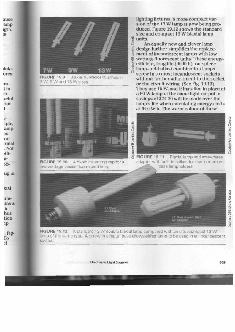
8/19/2019 Applications Electrical
http://slidepdf.com/reader/full/applications-electrical 314/447
FIGURE 19.9 Biaxial fluores cen t lamps in
7 W , 9 Wand 13 Wsizes
FIGURE 19.10 A bi-pin mo unting cap for
a
low wattage biaxial fluorescent lamp
lighting fixtures, a more co m pac t ver
sion of the 13 W lamp is now being pro
duced. Figure 19.12 shows the standard
size and co mpac t 13 W biaxial lamp
units.
An equally new and clever lamp
design further simplifies the replace
ment of incandescent lamps with low
wattage fluorescent units. These energy-
efficient, long-life (9000 h), one-piece
lamp-and-ballast
combination lamps
screw in to most incande scent sockets
without further adjustment to the socke
or the circuit wiring. (See
Fig.
19.13)
They use
15
W, and if installed in place o
a 60 W lamp of the sam e light outpu t, a
savings of $24.30 will be made over the
lamp 's life when calculating energy co sts
at 6<t/kWh. The warm colour of th ese
FIGURE 19.11 Biaxial lamp and screwbase
adapter with built-in ballast for use in medium
.-• '•' base lainpholders
FIGURE 19.12 A standard 13 W double biaxial lamp com pared w ith an ultra com pact 13 W
amp of the sam e type . A screw-in adapter base allows either lamp to be used in an incandescen
socket.
Discharge Light Sources 30

8/19/2019 Applications Electrical
http://slidepdf.com/reader/full/applications-electrical 315/447
FIGURE 19.13 A combination lamp and
ballast, globe typ e, for use in a m edium-base
lampholder
lamps will blend well with oth er incan
descent lamps that may be installed
nearby. Figure 19.14 shows typical use
these units.
The lamps do have som e limitation
though . Some manufacturers recom
mend that they not be used with dimna
switches, be allowed to come in
contad
with m oisture, or be used outdoors or I
enclosed fixtures where temperature
changes may be too extreme for safe
proper lamp use.
Power Groove Lamps
| During the late 1950s, a fluorescent rd
3 that used indentations, or grooves, on
f one side of the glass tube to increase
§
light output was developed. Later
g research showed that grooving both
| sides of the tube produced an even
I higher light output. (See Figs. 19.15 ani
8
19.16)
The grooves in the tube bring the
phosphor-coated glass closer to the
stream . This squeezing of the arc read
in more v isible light energy. In the pooa
groove tube, the arc stream must
folk*
a
wavy
path as it travels th e length
of
th e tube. (If the arc is straightened
ou
the re is approximately
2.7
m of arc
tained in the 2.4 m tube. This increase
and concentration of the arc length
allows the tub e to produce more light
than a conventional fluorescent tube.
g
The name
power
groove was
give*
this tube by one manufacturer. Power
groove lamps are useful light sources
I industrial applications. (See Fig. 19.11
3
C3
FIGURE 19 .14 T ypical application of a globe
type fluorescent lamp
| High-Intensity Discharge
E
Lamps
The term high-intensity discharge (HIL
describes a wide variety of lam ps. Be
310
Applications of Electrical Construction

8/19/2019 Applications Electrical
http://slidepdf.com/reader/full/applications-electrical 316/447
I P O W E R G R O O V E
1 '
A
m***^^
• r
o
FIGURE 19.15 P ower groove fluorescent tubes and sockets
Discharge Light Sources
311

8/19/2019 Applications Electrical
http://slidepdf.com/reader/full/applications-electrical 317/447
FIGURE 19.16 A power groove fluorescent
fixture for industrial applications
FIGURE 19.17 P ower groove lighting
installation
HID lamp s are alike in one way: they pro
duce light from a gaseous discharge arc
tub e and operate at a pressure above
that found in regular fluorescent lamps.
HID lamps were first introduced in
1934. They can be divided in to thre e
major categories: the mercury vapour
lamp, the m etal halide lamp, and the
high-pressure sodium lamp.
Mercury Vapour Lamps
In a sta nd ard , low-pressure fluorescen
tube,
most of the light energy is in the
ultraviolet range.
Phosphor-coated
tubes m ust be used to produce visibta
light. The higher-pressure mercury
vapour tube produces visible light
directly.
(See F igs. 19.18 and 19.19)
Some mercu ry vapour lamps have
phospho r coating on the inside of the
outer
bulb. This coating reacts to the
i
violet energy p rodu ced by the lamp
j
modifies th e colou r of the light outpi* .
The m ercury vap our lamp is pro
duced in sizes ranging from 50
W
to
1000
W
outp ut. Average life exp ectan t
is m ore tha n 24 000 h, which makes I
an ideal light so urc e w here re-lamp
both costly and time-consuming. The
me rcury vapo ur lamp is used for
strei
and road lighting, area lighting (for
exam ple, parking lots), and industrial
lighting in factories and
warehouses.
It
has several compon ents.
Base. The mogul screw-base found
most mercury vapour lamps connect
the lamp to the ballast and external
circuits. Letters (matching the
mondi
of the yea r) and nu m bers are imprinl^
in th e b ase . They he lp in keeping a
record of lamp life.
Sta rting Resistor. This tiny,
heat-withstanding resistor limits ci
in th e s tartin g circuit to a safe value.
Sta rting Electro des. The arc is
established between the main and
starting electrodes, ionizing the
argoi
gas and helping to strik e th e m ain arc
Main Electro des. Made of a double
layer of tungsten wire and coated w*
rare earth oxides, they ac t as termini
points for the main arc.
312
Applications of Electrical Con struction

8/19/2019 Applications Electrical
http://slidepdf.com/reader/full/applications-electrical 318/447
arc tube
arc tube s upport
base
pinch seal
start ing electrode
FIGURE 19.18 A clear mercu ry vapour lamp (400 W)
outer bulb
ma in elect rodes
<
FIGURE 19.19 A phosphor-coated mercury vapour lamp (1000 W)
o
Arc Tube Support. This polished metal
frame supports the arc tube and
conducts current to the upper main
electrode.
Arc Tube. This pure quartz tube is
called the heart of the mercury lamp. It
contains a precise quantity of mercury
and a small amount of argon gas. Some
manufacturers coat the ends of this tube
(around the electrodes) with platinum.
Doing so ensures that the tube will start
in cold weather.
Pinch
Seal.
It seals the ends of the arc
tube and prevents both the escape of
Discharge Ught Sources
31

8/19/2019 Applications Electrical
http://slidepdf.com/reader/full/applications-electrical 319/447
argon and th e entry of nitrogen. (Nitro
gen is used between the arc tube and the
outer tube.)
Outer Bulb. Heat- and
wea ther-resistant glass is used to
protect the internal parts and maintain a
nearly constant arc-tube temperature.
Maintaining a high arc-tube temperature
is important if the lamp is to operate
efficiently. T hes e bulbs are som etim es
pho spho r-coated , and they filter
ultraviolet light energy.
How a Mercury Vapour Lamp Produces
Light. The operation of the me rcury
lamp begins with the arc tube. Th ere is a
starting electrode beside the main
electrode
at one end of the tube.
Increased starting voltage from the
ballast (approximately do uble the line
voltage) strikes an a rc between th ese
two electrodes , using the argon gas as a
current path. The argon ionizes (breaks
up) and spreads rapidly throughout the
tube . As the ionized argon reac hes the
main electrode at th e op posite end of
the tube, the light-producing arc is
formed.
The small
starting resistor
(approxi
ma tely 40 k
Q)
limits th e arc curr ent dur
ing start ing . As a d irect re sult of its high
resista nce , curre nt flow quickly shifts to
the lower resistance, main arc stream.
Once the main arc has been established ,
cu rren t flow along its path is approxi
mately 1000 tim es grea ter tha n th e flow
between the starting electrodes.
Heat from th e main arc continue s to
vapourize the mercury in the a rc tub e for
several minutes after starting. As more
and more m ercury is vapourized, cur
rent flow in crea ses. Only the stabilizing,
current-limiting feature of the ballast
(similar to a fluorescent ballast)
preve nts th e lamp from d estroying itself.
Light energy is pro du ced by the
ic
ized argon gas pa rticle s colliding with
the mercury ato m s. As electro ns in the
mercury atom are jarred out of orbit |
replaced by electrons from a nearby
atom, radiation is given off. The coloirt
light (wave length) produced depends
on which ring of the o rbiting electro ns
ha s bee n hit by th e colliding particles*
argon. High pres sures in the arc tube ;
responsible for deeper penetration
in th e fluorescent tub e. This results
ii
more visible and less ultraviolet light
energy.
Horizontal Operation of Mercury'
Lamps.
The se lam ps are slightly i
efficient when operated while in a
vertical
position. Horizontal
operation
reduces the lamp's efficiency slightly
bec aus e th e arc will float u pw ards in 1
arc tube.
Restarting Mercury V apour Lamps.
the pow er supply to a mercu ry
vap
lamp is inte rrup ted, th e arc will
extinguish and not restart for several
m inute s. This is beca us e sufficient
pre ssu re will have built up in the tube
during operation to preven t the arc
]
re-establishing
itself
immediately, i
the tub e has cooled and the pressure
lowered, th e arc will re start
autom atically as usu al. Th ere is not
enough ballast voltage to restart the
lamp until it cools and the pressu re
i
the arc tube decreases.
Lamp life is sho rten ed by
contini
startin g. If a m ercu ry vap ou r lamp is
allowed t o o pe rat e for long period s of
time , its life sp an w ill be m uch long
Mercury Vapour Ballast.
Although
bulbs able to operate without
balla
have been designed, most mercury
vap our lamps need a ballast. The bz
314
Applications of Electrical Construction

8/19/2019 Applications Electrical
http://slidepdf.com/reader/full/applications-electrical 320/447
does for
HID
lam ps w hat it doe s for fluo
rescent lamps. Line voltage is boosted
slightly, lamp current is stead ied, a nd
the power factor is corrected.
Figures
19.20,19.21,
and 19.22 show
a ballast circuit, a cutaway view of an
outdoo r weatherproof unit, and an
indoor model with the sam e circuitry as
the outdoor unit.
Mercury V apour Applications. For
many years m ercury vapo ur lighting was
used to replace incande scent lighting
system s over roadways. Although m ore
recent lamp developmen ts are now
replacing mercury vapour in these
areas ,
shopping malls, commercial build
ings, and safety and security systems—
plac es wh ere dusk to dawn lighting is
required—still
make use of mercury
vapour lighting.
Figure
19.23
show s the difference in
street light output.
Figures
19.24,19.25,
and 19.26 show
mercury vapour lighting used for area
ballast -
voltage taps
power factor correction
capacitor
O O
live
120 V
neutral
O--
FIGURE 19.20 A me rcury vapour ballast circuit
Discharge Light Sources
31

8/19/2019 Applications Electrical
http://slidepdf.com/reader/full/applications-electrical 321/447
waterproof adhesives
waterproof ro l led seal
smooth drawn case
low temperature
dielectr ic capacitor
stainless steel band
colour-coded neoprene leads
(moulded in waterproof p lug)
removable handle
precis ion wound
coils
welded core
thermal barrier
FIGURE 19.21 A wea therproof me rcury vapour ballast
FIGURE 19.22 A n indoor mercury vapour ballast
316
Applications of Electrical Construction
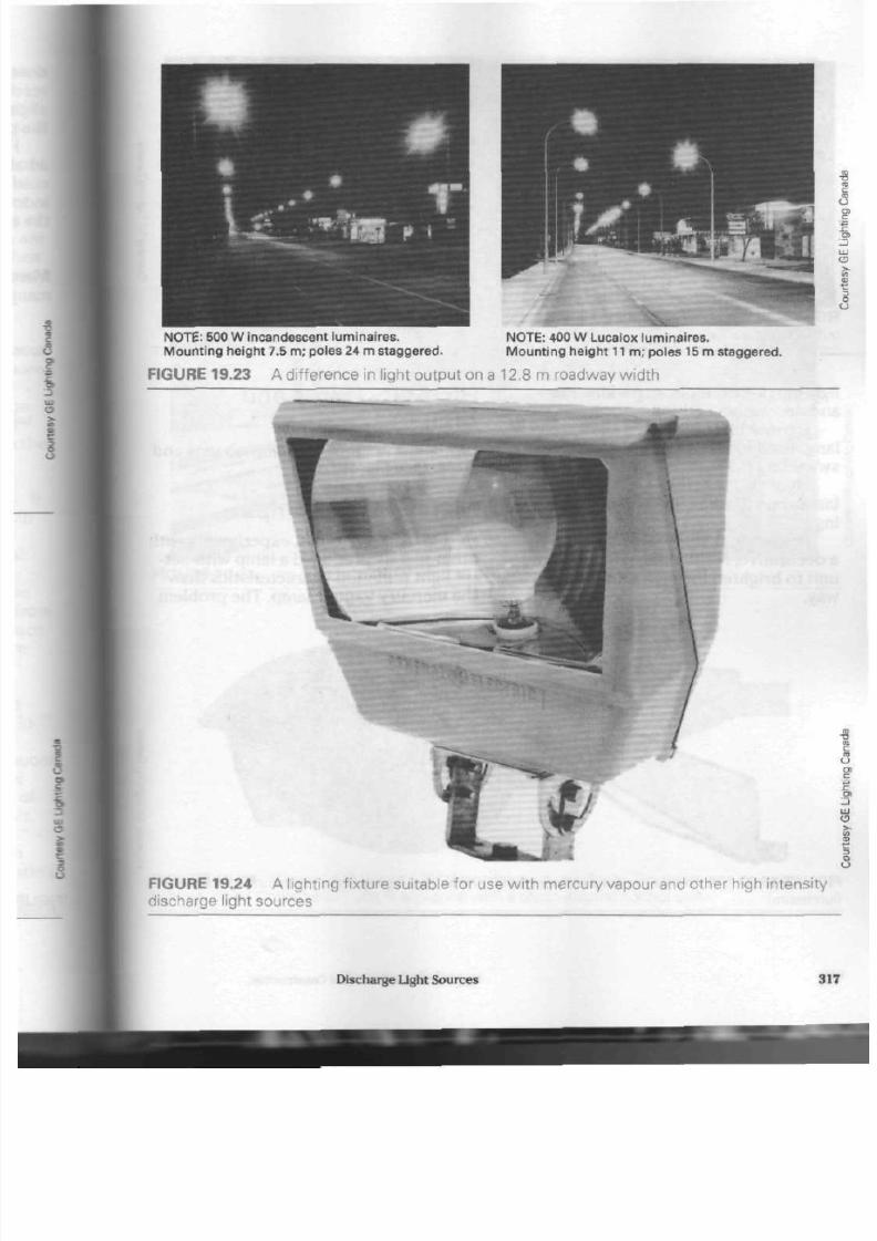
8/19/2019 Applications Electrical
http://slidepdf.com/reader/full/applications-electrical 322/447
N O T E :
500 W incandescent luminaires.
Mo unt in g height 7.5 m; poles 24 m s taggered.
N O T E :
400 W L ucalox luminaires.
M ount ing he ight
11
m; poles 15
m
s taggered.
FIGURE 19.23 A difference in light output on a 12.8 m roadway width
FIGURE 19.24 A lighting fixture suitable for use with mercury vapour and other high intensity
discharge light sources
Discharge Lig ht Sources 31

8/19/2019 Applications Electrical
http://slidepdf.com/reader/full/applications-electrical 323/447
o
0 1
8 FIGURE 19.26 Mercury vapour and
FIGURE 19.25 Me rcury vapour lighting for descent lighting used in com bination f
outdoor decorative use outdo or area lighting
lighting (for example, in parking lots)
and decorative lighting.
Figures 19.27 and 19.28 show a 250 W
lamp used for area lighting around a
swimming pool.
Figures 19.29 and 19.30 show 1000 W
lamps and fixtures used for a large park
ing lot.
Figure 19.31 shows this lamp used as
a decorative, residential, street lighting
unit to brighten the area around a
drive
way.
HID Lamp Sizes and
Shapes
HID lamps are made in many shapes |
sizes.
(See Fig. 19.32)
Metal Halide Lamps
During the early 1960s, experim ents'
other metals produced a lamp with I
ter light radiation characteristics
the m ercury vapour lamp. The prot
FIGURE 19.27 A 250 W me rcury vapour, metal halide, and high-pressure sodium light f
(luminaire)
318
Applications of Electrical
Construction

8/19/2019 Applications Electrical
http://slidepdf.com/reader/full/applications-electrical 324/447
FIGURE 19.28 A n outdoor area lit by a 250 W lamp unit
FIGURE 19.29 Typical 400 W or 1000 W high intensity discharge fixture for use in roadway
• h t i n g .
This "C obra he ad " unit is equipped with a photo-electric control
unit.
Discharge Light Sources
31
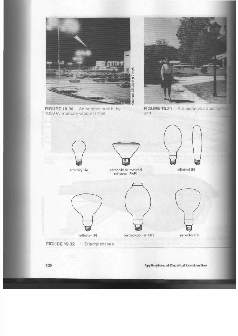
8/19/2019 Applications Electrical
http://slidepdf.com/reader/full/applications-electrical 325/447
FIGURE 19.30 A n outdoor area
lit
by
1000 W mercury vapour lamps
FIGURE 19.31 A decorative street
IN
unit
arbitrary (A) parabolic
aluminized
reflector (PAR)
elliptical (E)
reflector (R)
FIGURE 19.32 HID lamp shapes
bulged-tubular (BT) refle ctor (R)
320 Applications of Electrical Construction

8/19/2019 Applications Electrical
http://slidepdf.com/reader/full/applications-electrical 326/447
was to find m etals that could b e easily
vapourized bu t would remain chemically
stable. It was finally solved wh en me tals
in the form of thei r halide salts (usually
iodides) were adde d t o the basic m er
cury arc tube .
Today, lam ps u se iodid es of sodium,
thallium,
and
indium
along with the mer
cury in th e arc tub e. The result is a
metal halide lamp that can prod uce
50%
more light than a mercury lamp, with
greatly improved colour. (See
Figs. 19.33
19.34, and 19.35)
How a Metal Halide Lamp Produces
Light.
The ope ration of this lamp is
similar to that of the m ercury lamp, and
mo st m ercu ry lamp fixtures will readily
accept the halide lamps. A metal halide
ballast
must be used, however, becau se
\\*t\
4i<«r
FIGURE 19.33 A 400 W metal halide lamp
FIGURE 19.34 A 1000 W metal halide lamp
Discharge Light Sources
321

8/19/2019 Applications Electrical
http://slidepdf.com/reader/full/applications-electrical 327/447
quartz arc tub e
white reflective coating
electric discharge
through mercury plus
metallic iodide additives
bimetal switch
FIGURE 19.35 Internal com pone nts of a metal halide lamp
the lamp requires a higher voltage. The
fused quartz arc tube of a metal halide
lam p is slightly sm aller than t ha t of th e
me rcury lamp and h as a special coating
on the ends to m aintain proper elec
trode temp erature during operation. A
small bimetal switch is built in to the
lamp to short out the starting contacts
during operation . It helps to prolong
electrode life.
Metal halide lamps
will
maintain
about
40%
more light throughout their
useful life. This average s ou t to 15 000 h,
rated at 10 h operation pe r s tart.
Me tal Halide Lamp Applications. The
clear, heat-resistant glass bulbs need no
pho sph or coating, provide a better
colour than mercury vapour lamps, and
are used extensively to light sports
stadium s wh ere their colour and light
outpu t is com patible with the
requirem ents of colour TV cam eras .
Made in 175
W
to 1500
W
sizes, the se
lamps are also used for stores and other
comm ercial ap plications. Due to their
higher efficiency, they are gradually
replacing mercury va pour lamps as a
light source.
Figure 19.36 sh ow s a typical fixture.
It is used for ball park lighting and other
area lighting system s with many of the
FIGURE 19.36 A
P-1000
floodlight *
trunnion-type mount. For use with nert
vapour and me tal halide lamps.
HID lam ps. There mu st b e a ballast
th e circuit supplying th is fixture.
Figure 19.37 sho w s a m odern
ii
trial fixture design. The ballast is b
directly over the reflector on this 4
322
Applications of Electrical Construction

8/19/2019 Applications Electrical
http://slidepdf.com/reader/full/applications-electrical 328/447
FIGURE 19.37 A metal
ballast and reflector unit
door
Figure 19.38 show s a double-lamp
un it. It is useful for indu strial lighting
applications.
High-Pressure Sodium
Lamps
The high-p ressure sodium lam p is quite
different from other HID la m ps . It is
much simpler in design, beca use of the
t remendo us research and development
tha t went in to the prod uction of materi
als used in its construction. (See Fig.
19.39) It is reg ard ed as th e mo st efficient
source of white light artificially pro
duced. The 35 W, 50 W, 70 W, 100 W,
150 W 200 W 250 W 400 W and 1000 W
lamps put out approximately 50% more
light than either mercury vapour or
metal halide lamps of the same wa ttage
rating s. (See Figs. 19.40,19.41, and 19.42)
One reason for th e succe ss of th e
high-pressure sodium lamp is the
FIGURE 19.38
al halide lamp indoor ballast and double reflector unit
Discharge Light Sou rces
323

8/19/2019 Applications Electrical
http://slidepdf.com/reader/full/applications-electrical 329/447
arc tube support
exhaust tube (with amalgam
re
electric discharge
through sodium vapour coated tungsten electrodes
ceramic end cap
\
ceramic arc tube
FIGURE 19.39 Construction of a high-pressure sodium lamp
50Wto100W
^^ •PB^^
250 W
400
W
1000 W
FIGURE 19.40 High-pressure sodium lamps
324
Applications of Electrical Construction
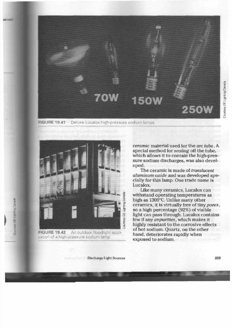
8/19/2019 Applications Electrical
http://slidepdf.com/reader/full/applications-electrical 330/447
FIGURE 19.41 Deluxe Lucalox high-pressure sodium lamps
FIGURE 19.42 A n outdoor floodlight appli
cation of a high-pressure sodium lamp
ceramic
m aterial used for the
arc tube.
A
special method for sealing off the tube,
which allows it to contain the high-pres
sure sodium discharges, was also devel
oped.
The ceramic is made of translucent
aluminum oxide and was developed spe
cially for this lamp. One trade name is
Lucalox.
Like many ceram ics, Lucalox can
withstand operating temperatures as
high as 1300°C. Unlike many othe r
ceram ics, it is virtually free of tiny pores
so a high percentage (92%) of visible
light can pass through. Lucalox contains
few if any
im purities,
which makes it
highly resistant t o the corrosive effects
of hot sodium. Q uartz, on the other
hand, deteriora tes rapidly when
exposed to sodium.
Discharge Light Sources
325

8/19/2019 Applications Electrical
http://slidepdf.com/reader/full/applications-electrical 331/447
The ceramic end caps are joined to
the a rc tu be in such a way that the y will
maintain the seal during the expansion
and contraction (heating and cooling)
cycles of the tu be . The oxide-embedded
electrodes and the end caps are also
designed to withstand the corrosive
effects of hot sodium.
Th e tub e is filled w ith a m ixture of
xenon and mercury as well as sodium.
A
special c ircuit consisting of a small elec
tronic board pro duc es a high voltage
pulse (2500 V) for about 1
u.
s during
each half of the alternatin g c urre nt
cycle. This voltage p ulse is stron g
enough to ionize the xenon acros s t he
main electrode gap, making starting
electrodes unnecessary. Once the arc
has been estab lished, th e high voltage
pulsing is discontinued and n ormal bal
last voltage m aintains the a rc.
Th ese lam ps reac h full brilliancy in a
sho rter period of time than me rcury or
metal halide lam ps. Also, they may b e
resta rted without waiting for the tub e
pressure to drop.
Colour changes in the lamp can be
seen as the sodium becomes fully
vapourized. A dim, bluish white light is
given off as the xenon ionizes. This
chan ges quickly to a brighter
mercury-
blue glow as tem pera ture rises in the
tube . A
yellow
shade takes over
from
the
blue, showing that the sodium has
reached low-pressure temperature. As
temp erature and pressu re in the tub e
reach norm al operating levels, the
colour changes to the white light seen
during operation. The arc temperature is
over 2000°C when t he lam p is at norm al
operating tem perature.
Lucalox lamps were m ade at one
time in tw o different m odels for base up
or
base down
o peration. Each could
op erate in a near horizontal position.
The reason for this wa s tha t the ex cess
LUCALOX LAMP CONSTRUCTION
E N D C L A M P
O U T E R B U L B
V A C U U M
L U C A L O X C E R A M I C
A R C T U B E
A R C T U B E
S T R U C T U R E
A M A L G A M
l i C R E l - r i A T E D
1 Q C 0 L
B A S E
FIGURE 19.43 A ne w h igh- pres s ure si
l a m p ,
sui table for use in any burning posh
sodium mixture collected at the cook
point in the a rc tub e. A special reser
was fitted to the arc tub e at th e cook
end of the lamp to collect it. In base
i
lamp s, the reservoir was p laced at the
end farthest from th e ba se. In bas e i
units, the reservo ir was placed near
I
bas e of the lam p.
Mo dern Lucalox lam ps are univer
burning, th at is, they bu rn in any posi
tion, and they have an external
amah
reservoir located a t one end of the arc
tube . This special rese rvoir contains
I
excess sodium amalgam, keeping it;
from th e arc stream, and thereb y
ext«
ing the life spa n of the lam p. The se
lam ps are available in both clear and i
fused coated versio ns to accommc
the v arious light distribution and li
naire requ irem ents. The clear lamps |
vide the best optical control of the I
energy, while th e difuse-coated lamps
provide a smoother, but lower bright
ne ss light in low-m ounted, decora tive
applications. Figure 19.43 illustrates
new lamp.
Deluxe Colour High-Pressure Sodium
Lamps.
The most recent lamps
provide a major improvement in the
app ear anc e of people, foliage, and
326
Applications
ol
Electrical C onstruction
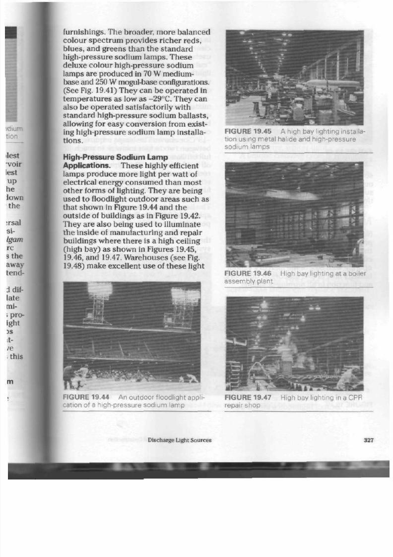
8/19/2019 Applications Electrical
http://slidepdf.com/reader/full/applications-electrical 332/447

8/19/2019 Applications Electrical
http://slidepdf.com/reader/full/applications-electrical 333/447
FIGURE 19.48
lighting system
jrehouse
storage area
sourc es as w ell. The trem end ous light
output of this form of lighting makes it
suitab le for roadway lighting installa
tions as seen in Figure 19.49.
Mult i-Vapour Lamps
New high efficiency, multi-vapour lamps
provide use rs with
50%
more light o ver
th e life of the lam p than t he older mer
cury vapou r lam ps. The se lamps will
opera te with
80%
of the m ercury v apour
ballasts now in use, indoo rs or ou tdo ors,
and function in all burnin g pos itions.
The lamps, rated at 400 W, are pr
in clear and phosphored glass units,
clear lamp provides good colour
and|
useful where good light control and
"cut off" are important considera
lighting. The phosphor coated lamp
vides even better colour when a
diffused light source is needed.
These lamps, which operate on =
mixture of metal halides rather than
one,
such as the mercury or sodium
lam ps, are suita ble for use in all wi
cond itions where the tem peratu re is
-18°C or ab ove. The lamps require
between two to four minutes to read
full brilliancy and will res tar t after s i
off in 10 t o 15 min. This ty pe of lamp
recom me nded for use by energy c
scious users of lighting systems
funds are not available for complet
tern
change-over
to ne we r light fo
The lamps h ave an average rated
span of
15
000 h b ased on 10 h o
per start.
As well as being used to m od
the less efficient mercury vapour
system s, multi-vapour lamps are
ble for new system installations,
sal (any position) burning, greatly
increased light output, and lower
i
co st ar e just a few of the re aso ns for
selecting this ty pe of lam p. It is
higH
FIGURE 19.49 Highway 400 lighting syste m w ith Lucalox lamps
328
Applications of Electrical Construction
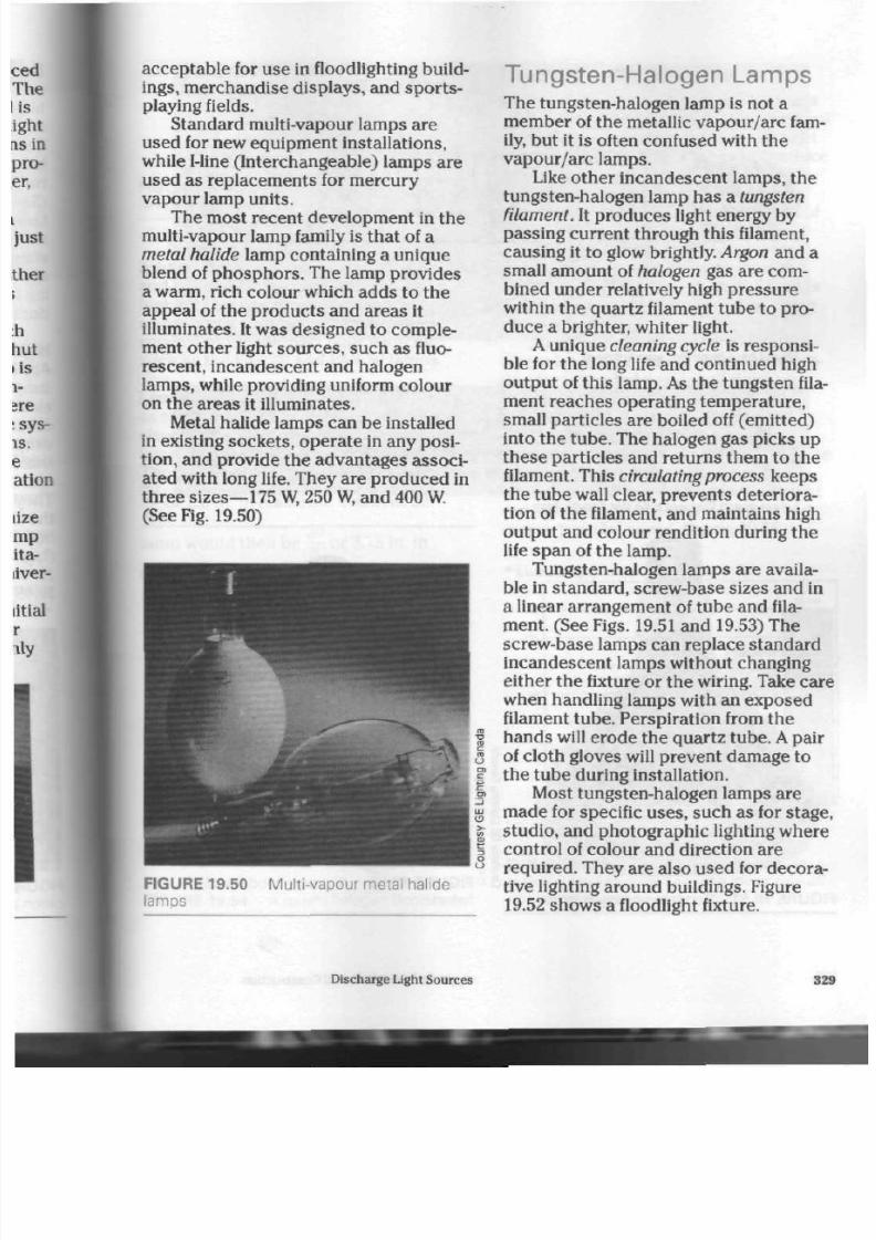
8/19/2019 Applications Electrical
http://slidepdf.com/reader/full/applications-electrical 334/447
acceptable for use in floodlighting build
ings,
merchandise displays, and sports-
playing fields.
Standard multi-vapour lamps are
used for new equipment installations,
while Mine (Interchangeable) lamps are
used as replacements for mercury
vapour lamp u nits.
The most recent development in the
multi-vapour lamp family is tha t of a
metal halide lamp containing a unique
blend of ph os ph ors . The lamp prov ides
a warm, rich colour which add s to th e
appeal of the prod ucts and are as it
illuminates. It wa s designed to co mp le
ment other light sources, such as fluo
rescent, incandescent and halogen
lamps, while providing uniform colo ur
on the areas it illuminates.
Metal halide lamps can be installed
in existing socke ts, ope rat e in any posi
tion, and provide the advan tages associ
ated w ith long life. Th ey are p rod uce d in
three sizes—175 W, 250 W, and 400 W.
(See Fig. 19.50)
FIGURE 19.50
lamps
Multi-vapour metal halide
Tungsten-Halogen Lamps
The tungsten-halogen lamp is not a
member of the metallic vapour/arc fam
ily, but it is often co nfused with th e
vapou r/arc lamps.
Like oth er incand escent lamps, the
tungsten-halogen lamp has a
tungsten
filament. It produces light energy by
passing current through this filament,
causing it to glow brightly.
Argon
and a
small amount of halogen gas are com
bined under relatively high pressure
within the quartz filament tube to pro
duc e a brighter, whiter light.
A unique cleaning cycle is responsi
ble for the long life and continued high
outp ut of this
lamp.
As th e tu ng sten fila
ment reaches operating tempe rature,
small particles a re boiled off (em itted)
into the tube . The halogen gas picks up
these particles and returns them to the
filament. This circulating process keeps
the tu be wall clear, preve nts deteriora
tion of th e filament, and ma intains high
outpu t and colour rendition during the
life span of the lamp.
Tungsten-halogen lamps are availa
ble in standard, screw-base sizes and in
a linear arrange m ent of tube and fila
ment. (See Figs. 19.51 and 19.53) The
screw-base lamps can replace standard
incandescent lamps without changing
either the fixture o r th e wiring. Take care
when handling lamps with an exposed
filament tube. Perspiration from the
han ds will ero de the quartz tu be.
A
pair
of cloth gloves will preven t dam age to
the tu be during installation.
Most tungsten-halogen lam ps are
m ade for specific u ses, suc h as for stage ,
stud io, and pho tograp hic lighting wh ere
control of colour and direction are
required. They are also used for decora
tive lighting around buildings. Figure
19.52 shows a floodlight fixture.
Discharge Light Sources
329

8/19/2019 Applications Electrical
http://slidepdf.com/reader/full/applications-electrical 335/447
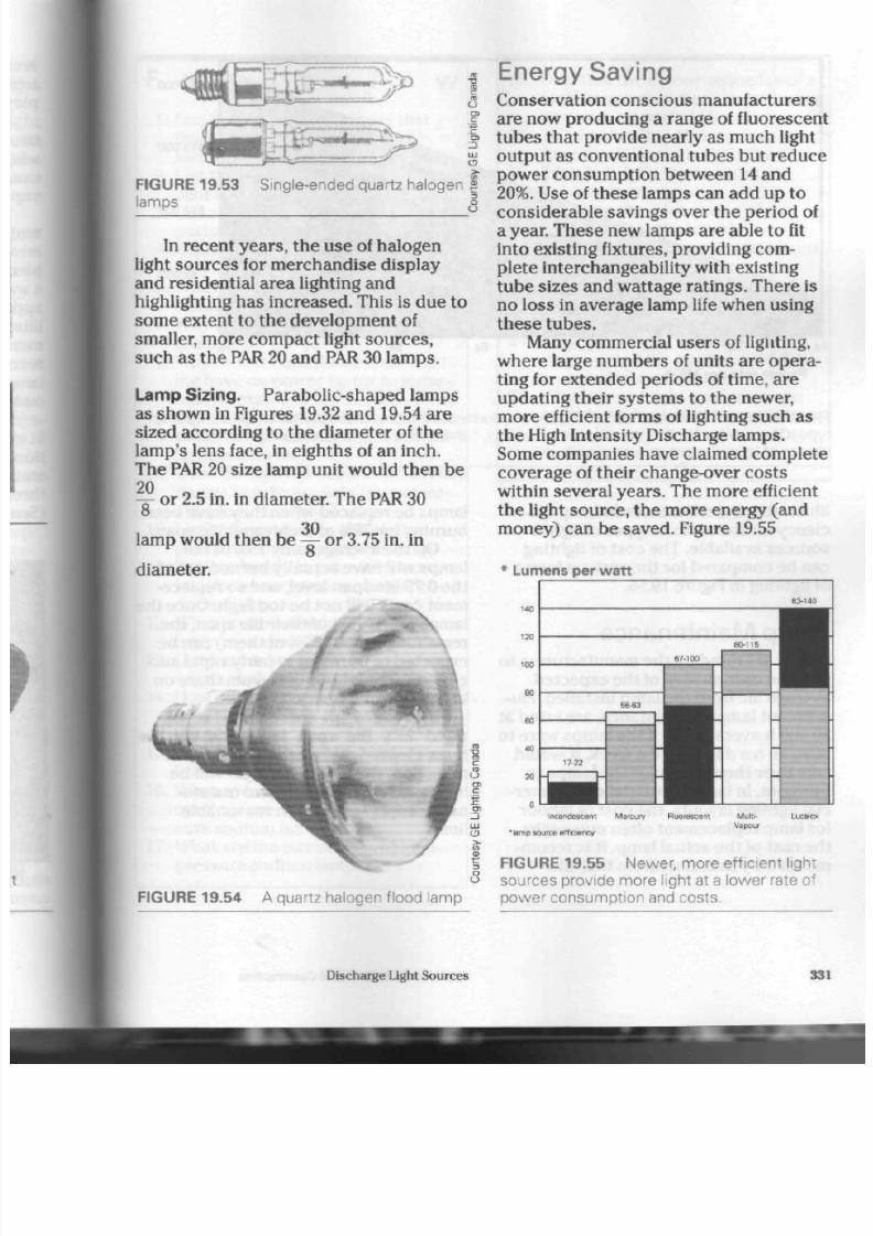
8/19/2019 Applications Electrical
http://slidepdf.com/reader/full/applications-electrical 336/447
" ^ ^ V I E nergy S aving
fc— '
.
fn iKPrvatinn
r-nncr-in
FIGURE 19.53
lamps
Single-ended quartz halogen f
In recent yea rs, the use of halogen
light sou rces for merch andise display
and residential area lighting and
highlighting has increased. T his is du e to
som e extent to the developm ent of
smaller, more comp act light sourc es,
such as the
PAR
20 and PAR 30 lam ps .
Lamp Siz in g. P arabolic -shaped lamps
as sho w n in Figures 19.32 and 19.54 are
sized according to the diam eter of th e
lamp 's lens face, in eigh ths of an inch.
The PAR 20 size lamp unit would the n be
20
-=-
or 2.5 in. in d iam eter. T he PAR 30
o
30
lamp would then be
-=-
o r 3.75 in. in
diameter.
Conservation conscious manufacturers
are now producing a range of fluorescent
tubes that provide nearly as much light
output as conventional tubes but reduce
power consu mp tion between 14 and
20%. Use of these lamps can add u p t o
cons iderable savings over th e period of
a year. Th ese new lam ps are ab le to fit
into existing fixtures, providing com
plete interchangeability with existing
tub e sizes and wattage rating s. There is
no loss in averag e lam p life when using
these tub es .
Many comm ercial u se rs of lighting,
wh ere large num bers of units are opera
ting for exten ded per iod s of time, are
updating their systems to the newer,
more efficient forms of lighting such as
the High Intensity Discharge lamps.
Some companies have claimed complete
coverage of their change-over cos ts
within severa l year s. The m ore efficient
the light sourc e, the m ore energy (and
mo ney) ca n b e save d. Figure 19.55
* Lumens per watt
140
120
100
so
60
40
20
n
67-100
17 22
S&63
80-116
83-140
ncandescent Mercu ry Fluorescent
•lamp source efficiency
M u l t -
Vapour
FIGURE 19.54 A quartz halogen flood lamp
FIGURE 19.55 N ewer, more efficient light
sources provide more light at a lower rate of
power consumption and costs.
Discharge Light Sources
331

8/19/2019 Applications Electrical
http://slidepdf.com/reader/full/applications-electrical 337/447
$z:
•
$•:
S:
U 2« 3«
P ow er ra t e per
kW-h
8C
FIGU R E 19. 56 A c ompa r is on o f t he c os t t o i ll uminat e 2000 m
?
t o 540
Ix
for a year by
I
t y pe. (The s y m bol " I x " i s t he s ho r t f orm f or " lu x , " t he m et r ic un i t f or mea s ur ing i llumine
source of l ight per unit area on a surface.)
illustrates the differences in lamp effi
ciency for the vario us t yp es of light
sou rce s available. The co st of lighting
can be comp ared for the various forms
of lighting in Figure 19.56.
Lamp Maintenance
Lamps are rated by the man ufacturers to
give the user an idea of the expec ted
average life from the lamp installed. Flu
ores cen t lamp s, for instance , are rated at
20 000 h average life. If the lamps were to
bur n 20 h a day for 6 d a week, it would
take over three y ears for the lamps to
burn out. In large industrial or commer
cial lighting layouts, the co st of labou r
for lamp replacement often outweighs
the cost of the actual lamp. It is recom
mended by manufacturers that the
lamps be replaced when they have
I
burning for
75%
of their rated life s |
On the average, only
15%
of the
lamps will have actually burned out
i
the 0.75 life span level, and so
repl
ment
c os ts will not be to o high. Or
lamps reach
75%
of their life span .
rJ
remaining lamps
(85%
of them ) can
I
exp ecte d to bu rn o ut in fairly rapid
i
cession. The labour co st from there
in can be quite heavy.
If all the lam ps are replac ed at tl
rat ed 75% life span level and thi
tures cleaned and washed to
increaa
reflection, the amount of light will be
increased considerably and mainte
nance costs kept within reasonable
limits.
332
\ppl\cat\ons of Electrical Construction

8/19/2019 Applications Electrical
http://slidepdf.com/reader/full/applications-electrical 338/447
F o r R e v i e w
1. List thr ee main adv anta ges that
fluorescent lighting has over
incandescent lighting.
2.
List the disadvantages of fluores
cent lighting.
3.
List and explain th e us e of th e
parts of the fluorescent tube.
4. Explain how a sta rter ope rates in a
preheat lamp.
5. W hat are the two functions of the
ballast? How does it work?
6. Why must rapid-start fixtures be
grounded?
7. What effect does fluorescent light
ing have on pow er factor in indus
trial plants?
8. What are man ufacturers now
doing to prevent damage from bal
last overheating?
9. What change has been made in the
design of tube so cke ts for instant-
start fixtures? Why?
10.
List and explain the use of the
par ts of a me rcury vapo ur lamp .
11. Explain briefly in your own words
how a me rcury vapo ur lamp pro
duces light.
12.
W hat are the disadv antages of
me rcury vapou r lighting?
13. List four areas of use for mercury
vapour lighting.
14. How does a m etal halide lamp
differ from a mercury vapour
lamp?
15. What are the ad vantages of metal
halide lamps?
16. What special material was devel
oped for use with the high-pres
sure sodium lamp?
17. What are the advantages of high-
pressure sodium lamps?
18.
Describe the colour sequ enc e of a
high-pressure sodium lamp during
its warm-up period.
19. To what family of lamps does the
tungsten-halogen lamp belong?
20.
Explain briefly how a tun gste n-
halogen lamp works.
21 . What are the advan tages of the
tungsten-halogen lamp?
22 . What type and size of metric lam p
is available?
23. What two me thod s can be used to
con serve energy when using a
lighting system?
24.
At what point in a fluorescent
lamp's rated life span should it be
replaced ? Explain why.
25.
What type of light sourc e can be
used to replace mercury vapou r
lamps for improved lighting co sts
and energy conservation?
Discharge Light Sources
333

8/19/2019 Applications Electrical
http://slidepdf.com/reader/full/applications-electrical 339/447
E
lectrical motors are used for a wide
variety of residential, commercial,
and industrial ope ration s. Because of
this, guidelines are necessary. This
ch apte r deais with the need for motor
control and some of the more common
control systems.
T he N eed for S pecial
Contro l Equipment
Electrical m otors op erate on magnetism.
The amou nt of current n eeded to crea te
the magnetism depends on the size and
design of the motor.
Nearly all m otors tend to d raw muc h
more current during the starting period
(starting curre nt) than w hen rotating at
operating speed (running current).
Motors are rated in horsepower or
wa tts. The higher th e rating of th e
motor, the higher the starting and run
ning curre nts will be.
Every motor tends to produce a
counter voltage and current within its
winding s. This generator action pro
duces a voltage and current that flows
opposite to the applied current; in fact,
the g enerated current flow he lps to con
trol the flow of incoming curre nt throu gh
the motor. Manufacturers design motors
with this current in mind. Prope r co ntrol
Motor
Control
of incoming cu rren t ex tend s th e life I
of the motor. Excessive input c urrent
will severely damage or burn the moti
windings.
One main factor in determ ining
thi
amoun t of generated v oltage and
ci
in the m otor is its
speed.
If th e load
placed on a motor reduces the speed,
less gene rated curr ent will be develc
and more applied current will flow,
is ,
t he greater the load on th e m otor, I
slower it will rotat e and t he more
applied cu rren t will flow throu gh its
windings. This is why a m otor req uire
more cu rrent du ring the starting per
most electrical mo tors hav e a starting
current that is three to five times' the
normal running current.
As the speed picks up, the gener
voltage within the motor gradually
increa ses. However, the instant the I
ing switch is closed, no generated vol
age exists and the applied current
becom es very high.
If
the motor is
jammed or prevented from rotating ii
any way, a locked rotor condition
is'
ated. The part of the motor that rota
is often called the
rotor.
When the:
fails to tu rn, th e exc essive app lied i
rent is called th e locked rotor
current.
This high current will cause the
mote
burn out quickly.
334
Applications of Electrical C onstruction
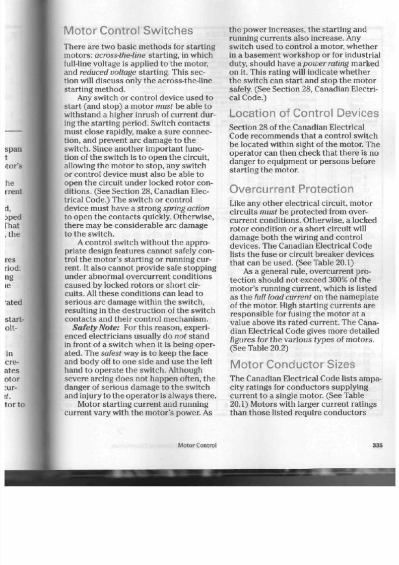
8/19/2019 Applications Electrical
http://slidepdf.com/reader/full/applications-electrical 340/447
Motor Control Switches
There are two basic meth od s for starting
motors : across-the-line starting, in which
full-line voltage is applied to the motor,
an d reduced voltage starting. This sec
tion will discu ss only the across-the-line
starting method.
Any switch or con trol device used to
start (and stop) a motor must be able to
withstand a higher inrush of curre nt dur
ing the starting period. Switch con tacts
must close rapidly, make a sure co nnec
tion, and prevent arc damage to the
switch. Since anothe r im portant func
tion of the switch is to open the circuit,
allowing the motor to stop, any switch
or control device must a lso be able to
open the circuit un der locked rotor con
ditions . (See Section 28, Canadian Elec
trical Code.) The switch or control
device must have a strong
spring action
to open th e con tacts quickly. Otherw ise,
there may be considerable arc damage
to the sw itch.
A
control switch without the appro
priate design features cannot safely con
trol the m otor's starting or running cur
rent. It also cannot provide safe stopping
under abnormal overcurrent co nditions
caused by locked rotors o r sho rt cir
cuits. All these conditions can lead to
serious arc dam age within the switch,
resulting in the destruction of the switch
contacts and their control mechanism.
Safety Note:
For this reas on , experi
enced electricians usually do
not
stand
in front of a switch when it is being oper
ated. The
safest
way is to ke ep th e face
and b ody off to on e side and us e the left
hand to operate the switch. Although
severe arcing doe s not happen often, th e
danger of serious damag e to the sw itch
and injury to the ope rato r
is
always the re.
Motor starting current and running
curren t vary with the mo tor's power. As
the power increases, the starting and
running curre nts also increase . Any
switch used to control a motor, wh ether
in a basem ent wo rkshop or for industrial
duty, should h ave a
power rating
marked
on it. This rating will indicate w he ther
the switch can start and stop the motor
safely. (See Section 28 , Can adian Electri
cal Code.)
Location of Control Devices
Section 28 of the Canadian Electrical
Code recommends that a control switch
be located within sight of the motor. The
operator can then check that there is no
danger to equipment or persons before
starting the motor.
Overcurrent Protection
Like any other electrical circuit, motor
circuits
must
be protected from
over-
curre nt cond itions. Otherwise, a locked
rotor condition or a short circuit will
damag e both th e wiring and control
devices. The Canadian Electrical Code
lists the fuse or circuit breaker devices
tha t can be use d. (See Table 20.1)
As a general rule, overcu rrent pro
tection should not exceed 300% of the
m otor's runn ing curren t, which is listed
as the full load current on the namep late
of the motor. High starting currents are
responsible for fusing the motor at a
value above its rated curre nt. The Cana
dian Electrical Code gives more detailed
figures for the va rious typ es of moto rs.
(See Table 20.2)
Motor Conductor Sizes
The Canadian Electrical Code lists ampa
city ratings for cond ucto rs supplying
cu rren t to a single motor. (See Table
20.1) Motors with larger current ratings
than those l isted require cond uctors
Motor Control 33

8/19/2019 Applications Electrical
http://slidepdf.com/reader/full/applications-electrical 341/447
TABLE 20. 1
Full-
Load
Current
Rating
of
Motor
Amperes
1
2
3
4
5
6
7
8
9
10
11
12
13
14
1 5
1 6
17
18
19
2 0
22
2 4
2 6
2 8
3 0
3 2
3 4
3 6
3 8
4 0
4 2
4 4
4 6
4 8
5 0
52
54
56
58
6 0
C ol .
1
Minimum
Allowable
Ampacity
of
Conductor
15
15
15
15
15
15
15
15
15
1 5
15. 00
15. 00
1 6 . 2 5
17.50
1 8 . 7 5
2 0 . 0 0
2 1 . 2 5
2 2 . 5 0
2 3 . 7 5
2 5 . 0 0
27. 5
3 0 . 0
3 2 . 5
3 5 . 0
3 7 . 5
4 0 . 0
4 2 . 5
4 5 . 0
4 7 . 5
50. 0
52. 5
5 5 . 0
57. 5
60. 0
62. 5
65. 0
67. 5
70. 0
7 2 . 5
75. 0
Col. 2
Overload P rotection
for Running
Protection of Motors
Maxi
mum
Rating of
Type D
Fuses
Amperes
1.125
2.225
3. 5
4. 5
5.6
7
8
9
10
12
12
1 5
1 5
17. 5
17. 5
17. 5
2 0
2 0
2 0
2 5
2 5
3 0
3 0
3 5
3 5
4 0
4 0
4 5
4 5
5 0
5 0
5 0
5 0
6 0
6 0
6 0
6 0
7 0
7 0
7 0
C ol .
3
Maxi
mum
Setting of
Overload
Devices
Amperes
1.25
2. 50
3. 75
5. 00
6. 25
7. 50
8. 75
10. 00
11.25
12. 50
13. 75
15. 00
16. 25
17. 50
18. 75
2 0 . 0 0
2 1 . 2 5
2 2 . 5 0
2 3 . 7 5
2 5 . 0 0
2 7 . 5
3 0 . 0
3 2 . 5
3 5 . 0
3 7 . 5
4 0 . 0
4 2 . 5
4 5 . 0
4 7 . 5
50. 0
52. 5
5 5 . 0
57. 5
6 0 . 0
62. 5
6 5 . 0
6 7 . 5
70. 0
72. 5
75. 0
Col.
4
Overcurrent P rotection Maxim um Allowable
Rat ing
i
Fuses and M a x i m u m A l l o w a b l e S e t t in g of Circuit
Breakers of the
Time-Limit
Type for Motor Circuits
Single P hase
All Types
and
Squirrel Cage
and
Synchronous
(Full V oltage,
Resistor and
Reactor Starting)
Fuse
Amperes
1 5
1 5
1 5
15
1 5
2 0
2 5
2 5
3 0
3 0
3 0
4 0
4 0
4 5
4 5
5 0
6 0
6 0
6 0
6 0
6 0
8 0
8 0
9 0
9 0
1 0 0
1 1 0
1 1 0
1 2 5
1 2 5
1 2 5
1 2 5
150
1 5 0
150
175
175
1 7 5
175
2 0 0
C ol .
5
Circuit
Breaker
Amperes
15
15
1 5
1 5
1 5
1 5
15
2 0
2 0
2 0
3 0
3 0
3 0
3 0
3 0
4 0
4 0
4 0
4 0
5 0
5 0
50
7 0
7 0
7 0
7 0
7 0
100
100
100
1 0 0
100
100
100
1 2 5
1 2 5
1 2 5
1 2 5
125
150
C ol .
6
Squirrel Cage
and
Synchronous
(Auto-transformer
and
Star-Delta
Starting)
Fuse
Amperes
15
15
1 5
1 5
1 5
1 5
15
2 0
2 5
2 5
3 0
3 0
3 5
35
4 0
4 0
4 5
4 5
5 0
5 0
6 0
6 0
7 0
7 0
7 0
7 0
7 0
80
80
8 0
90
9 0
100
100
100
1 1 0
110
125
125
125
C o l .
7
Circuit
Breaker
Amperes
15
15
15
15
1 5
15
1 5
1 5
1 5
2 0
2 0
2 0
3 0
3 0
3 0
3 0
30
3 0
4 0
4 0
4 0
4 0
5 0
5 0
5 0
7 0
7 0
7 0
7 0
7 0
7 0
1 0 0
100
100
100
1 0 0
100
100
100
100
Col. 8
DCorV
Roto
Fuse
Amperes
15
15
15
1 5
1 5
1 5
15
15
15
15
2 0
2 0
2 0
2 5
2 5
2 5
3 0
3 0
3 0
3 0
3 5
4 0
4 0
4 5
4 5
5 0
6 0
6 0
6 0
6 0
7 0
7 0
7 0
8 0
8 0
8 0
9 0
9 0
9 0
90
Col. 9
if
Voatf
rAC
c» a
For full information of conditions that may change the values in this
table,
see the corresponding table in the Canadian Electrical (
336
Applications of Electrical C onstruction

8/19/2019 Applications Electrical
http://slidepdf.com/reader/full/applications-electrical 342/447
TABLE 20.2 R at ing or S et t ing o f O v erc urrent D ev ic es f or t he P rot ec t ion o f
Motor Branch Circui ts
Type of Mo tor
A l ternat ing C urrent
Single-phase al l types
Squi r re l - c age and Sy nc hronous :
Ful l -vol tage Start ing
Resis tor and Reactor Start ing
A u t o - t ra n s f o r m e r S t a r ti n g :
N o t m o r e t h a n 3 0 A
M o r e t h a n 3 0 A
W o u n d R o t o r
Direct Current
N o t m o r e t h a n 4 0 kW
M o r e t h a n 4 0 k W
P er Cent of Full Load Current
Fuse
Rating
300
3 0 0
300
250
200
150
150
150
Max imum
Circuit-Breaker
Setting
Instan
taneous
Type
—
7 0 0
—
—
—
—
250
175
Time-
Limit
Type
250
250
250
200
200
150
150
150
For full information of conditions that may change the values in this table, see the corresponding table in the Canadian Electrical Code.
(Note that the 40 kW m otors were form erly rated as 50 horsepower motors.)
with ratings equal to 125% of the
motor's full load current.
Motors that are operated for short
periods can be supplied with conduc
tors that have a somewhat lower current
rating. The C anadian Electrical Code
shows how to determine condu ctor
am pacities. (See Table 20.3)
When conduc tors are used to supply
two or more m otors on th e same circuit,
conductor ampacity can be determined
by adding th e full load c ur ren ts of all the
mo tors in the circuit; then 25 % of the
largest m otor 's full load cu rren t is add ed
to th e total. (See Section 28, Canadian
Electrical Code.)
Thermal Overload Relay
Protection
Often a moto r is loaded beyond its
designed capacity. Motors in wood- and
metal-cutting machines, pumps, hoists,
and fans are examples of where over
loading can occur. Overloading slows
down the m otor, which results in less
genera ted voltage and an increase of
input cu rrent. For example, when using a
saw, if th e bo ard is da m p or the cu t is
too deep, the motor
will
be overloaded
and slow down. The current flow in the
windings will increase and heat the
motor beyond i ts design tem perature.
A
jamm ed pu m p or an extra-heavy load on
a hoist will have the sam e effect on a
motor. Most electrical motors have
cooling fans or b lades built in, but su ch
cooling system becomes less and less
effective as the motor's speed is
reduced.
If
nothing is done, the re may b
permanent damage to the motor's wind
ings and expensive repairs will be
needed.
It is hum an n atu re to try for "one
Motor Control 33

8/19/2019 Applications Electrical
http://slidepdf.com/reader/full/applications-electrical 343/447
TABLE 20.3 Data for Determining Conductor Sizes for Motors of Different Duty Types
Classif icat ion of Service
Short-t im e Duty.
Operating valves, raising or lowering
rolls, etc.
Intermittent Duty.
Freight and passenger elevators, tool
heads, pumps, drawbridges,
turntables, etc.
Periodic Duty. Rolls, ore- and
coal-handling machines, etc.
V arying Duty.
P ercentage of N ameplat e
Current Rat ing of Motor
5
Min
Rat ing
110
8 5
85
110
15 30 and 60
Min Min
Rat ing Rat ing
120 150
85 90
90 95
120 150
Continues 1
Rating
140
140
2c:
more cut" or "one last load." Knowing
this, manufacturers have designed a
heat-sensitive mechanical device. When
a mo tor has been overload ed for a cer
tain length of time, this device , called a
thermal overload relay, opens the circuit.
(See Fig. 20.1) It doe s no t c au se " nui
san ce tripping," however, by opening
th e circuit every time the re is a brief o r
minor overload. The relay open s the cir
cuit only when the re is a prolonged over
load condition.
Modern 3 phase motor control units
require three overload relays to provide
full pro tectio n for the m otor. On so m e
manu facturers ' motor controllers, there
are three h eater un its with a m echanical
linkage. These relays operate a single set
of overlo ad co nt ac ts . (See Fig. 20.26 on
page 354.) Other manufacturers prod uce
motor controllers with bimetallic relays,
each having individual conta cts. Th ese
con tacts are connec ted in a series cir
cuit: any on e set of con tac ts o pen ing will
shu t down the mo tor sta rter if an over
load condition exists on the motor.
Relay Class Designations. There are
heater wir
solder pot
N O T E :
The solder pot is heat sensit ive. The
Ihetn
unit p rovides an accurate response to
ttie
overload current .
N O T E :
The heater winding is heat producing
manent ly jo ine d to the solder pot to ensui
proper heat transfer.
FIGURE 20. 1 Front and cutaway view s]
thermal overload relay unit
338
Applications of Electrical Construction
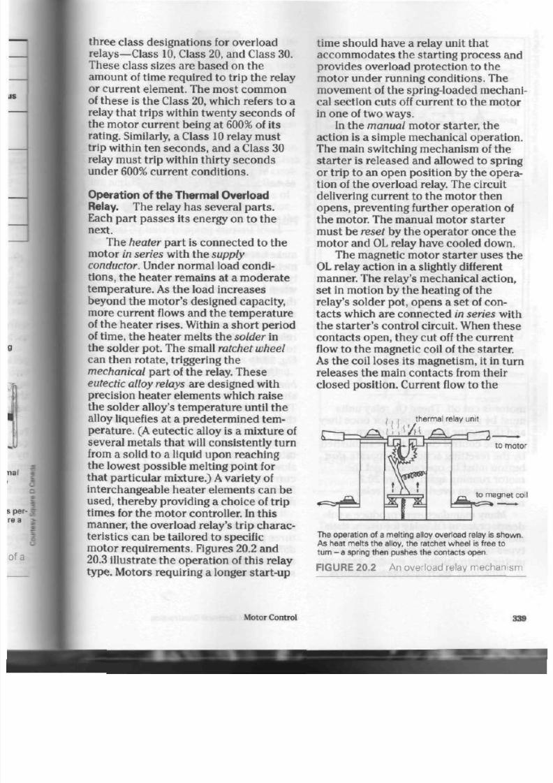
8/19/2019 Applications Electrical
http://slidepdf.com/reader/full/applications-electrical 344/447
three class designations for overload
relays—Class
10, Class 20, and Class 30.
These class sizes are based on th e
amount of time required to trip the relay
or current element. The most common
of the se is th e Class
20,
which refers to a
relay that trips within twenty seconds of
the mo tor curr ent being at 600% of its
rating. Similarly, a Class 10 relay m us t
trip within ten sec on ds , and a Class 30
relay must trip within thirty seco nds
under 600% current conditions.
Operation of the Thermal O verload
Relay. The relay has several pa rts .
Each part passes its energy on to the
next.
The heater part is connected to the
motor
in series
with the
supply
conductor. Under normal load condi
tions,
the heater remains at a mode rate
tem pera ture. As the load increases
beyond the m otor's designed capacity,
more current flows and the temperature
of th e hea ter ris es. Within a sh or t period
of time, the h eate r m elts the solder in
the so lder pot. The small ratchet wheel
can then rotate, triggering th e
mechanical part of the relay. These
eutectic alloy relays
are designed with
precision heater elements which raise
the solder alloy's tem pera ture until th e
alloy liquefies at a predetermined tem
pe ratu re. (A eutec tic alloy is a mix ture of
several metals that will consistently turn
from a solid to a liquid upon reaching
the lowest pos sible m elting poin t for
that pa rticular mixture.)
A
variety
of
interchangeable heater elements can be
used, there by p roviding a choice of trip
times for the motor controller. In this
manner, the overload relay's trip chara c
teristics can be tailored to specific
motor requirements. Figures 20.2 and
20.3 illustrate the operation of this relay
type. Motors requiring a longer start-u p
time should have a relay unit that
accom mo dates the starting process and
provides overload protection to the
motor under running conditions. The
mo vem ent of the spring-loaded m echani
cal section cuts off current to the motor
in one of two w ays.
In th e
manual
motor starter, the
action is a simple m echanical o peration .
The main switching mechan ism of the
sta rter is released and allowed to spring
or trip to an open position by the opera
tion of th e ove rload relay. The circuit
delivering current to the motor then
opens,
preventing further operation of
the motor. The manual motor starter
must be reset by the operator once the
motor and
OL
relay have cooled down.
The magnetic motor starter u ses th e
OL relay ac tion in a slightly different
manner. The relay's m echanical a ction,
set in motion by the heating of the
relay's solder pot, opens a set of con
tacts w hich are connected in series with
the s tart er's con trol circuit. When thes e
con tacts op en, they cut off th e cu rrent
flow to th e m agnetic coil of the starter.
As th e coil lose s its magn etism, it in turn
releases the main con tacts from th eir
closed position. Current flow to the
thermal relay unit
to motor
to magnet coi
The operation of a melting alloy overload relay is shown
As heat melts the alloy, the ratchet wheel is free to
turn -
a
spring then pushes the contacts open.
F IGU R E 20. 2 A n ov er load relay me c han is m
Motor Control

8/19/2019 Applications Electrical
http://slidepdf.com/reader/full/applications-electrical 345/447
Eutectic Alloy Overload Relay
reset position tripped position
power
circuit
ratchet
eutectic alloy
, heater
power
circuit
heater coil
FIGURES 20.3A AND B A eutectic alloy
solder-pot relay with a ratchet-wheel trip
mechanism
motor is cut off. These
OL
relay un its
must be reset by the op erator once they
and the motor have cooled down, but
only the control circuit is re-established
by the resetting action.
A
separate start
button must
be
operated
to
get th e
m oto r run ning again. Figure 20.2
illustrates an o verload (OL) relay
mechanism.
Many manufacturers produce
a
sol
der-pot type
of OL
relay
for
use in their
motor control equipment, but two other
types of relay can be found in various
motor control units.
Bimetallic
thermal overload relays
contact
FIGURE 20.4 A bimetallic overload'
make use
of a
simp le, U-shaped
strip*
metal (fabricated from two different
types of metal) which ben ds or defied
when h eated by the heater portion
a
th e relay. This ben ding action will opfl
set
of
con tacts and prevent further o
ation
of
the m otor.
In
many cases tha
relays are adjustable o ver a range oil
to 115% of nominal heate r ratings. (See
Fig. 20.4)
Unlike eu tectic alloy relays,
bimetallic
un its are often sensitive
to
shock and vibration, tripping n eedles
The two different m etals tha t make
9
the bending strip m ove gradually to
release the trip mechanism. This gra*
movement means that the electrical
a
tacts open slowly. Con tacts opened
slowly are pron e
to
arc damage
from 1
current in th e circuit. They can
flutten
fluctuate open and close, causing ev
more arc damage.
Some manufacturers produ ce,
pie
heater units that monitor each
of
three phases in
a
polyp hase system.
1
differential m echanism is used to pro
vide phase-loss
sen sitivity.
This, simf
stated, means that the motor
w ill:
340
Applications of Electrical Construction
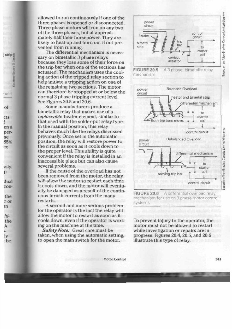
8/19/2019 Applications Electrical
http://slidepdf.com/reader/full/applications-electrical 346/447
allowed to run c ontinuo usly if on e of th e
three phases is opened or disconnected.
Three pha se m otors will run on any two
of the three phases, but at approxi
mately half their horsepower. They are
likely to heat up and burn out if not pre
vented from running.
The differential me chanism is nec es
sary on bimetallic 3 ph ase relays
because they lose some of their force on
the trip bar when one of the sections has
actuated . The mechanism uses the cool
ing action of the tripp ed relay section to
help initiate a tripping action o n on e
of
the remaining two section s. The m otor
can therefore be stopped at or below the
normal 3 phase tripping current level.
See Figures 20.5 and 20 .6.
Some manufacturers produce a
bimetallic relay that make s use of a
replaceable
hea ter elem ent, similar to
that used with the solder-pot relay type.
In the manual position, this relay
behaves much like the relays discussed
previously. Once set in the automatic
position, the relay will res tor e pow er to
the circuit as soon a s it cools dow n to
the pro pe r level. This ability is quite
convenient if the relay is installed in an
inaccessible place but can also ca use
several problems.
If the c aus e of the overlo ad ha s not
been removed from the motor, the relay
will allow th e moto r to re start e ach time
it cools down, and th e m otor will eventu
ally be damaged as a result of the co ntin
uous inrush cu rrents from the m any
restarts.
A second and more serious problem
for the operator is the fact the relay will
allow the mo tor to resta rt as so on as it
cools dow n, even if th e ope rato r is work
ing on the m achine at th e time.
Safety Note:
Great care m ust be
taken, when using the automa tic setting,
to open the main switch for the motor.
heater
bimetal
strip
control
circuit
to
starter
coil
contact
actuator
1
F I G U R E 2 0 . 5
m e c h a n i s m
A 3 phas e, bime tal l ic relay
power
circuit
Balanced Overload
\
\ \
/
[
r % — c * — L W _*.? »
heater and bimetal strip
differential mechanism
~f
•Both trip bars move.
to
starter
coil
I
power
circuit
control circuit
Unbalanced Overload
~ \
moving trip bar
differential mechanism
T
to
starter
coil
I
control circuit
F IGUR E 20.6 A d i f ferent ia l over load re lay
me cha nism for use on 3 phase m otor contro l
sys t e m s
To prevent injury to the op erator, the
motor must not be allowed to restart
while investigation or repa irs are in
pro gre ss. Figures 20.4, 20.5, and 20.6
illustrate this type of relay.
Motor Control
341

8/19/2019 Applications Electrical
http://slidepdf.com/reader/full/applications-electrical 347/447
FIGURE 20.7 Ma gnetic overload relay units
Magnetic
overload relays have a
mo veable, magnetic co re inside a coil
which is con nected in series with th e
mo tor supply leads that c arry current to
the motor. Normal operation of the
motor will allow the core to rest in such
a position that th e con tacts of the relay
are closed. When an overload condition
is experience d by the m otor, more cur
rent will be drawn by the m otor and the
coil. Th e magne tic attrac tion of the coil
will becom e stronge r than norm al, and it
will dra w th e core further into the relay.
As th e co re is pulled in to th e relay, it
ope ns th e conta cts in the relay that are
used to turn the motor starter off. To
prevent nuisance tripping, a piston-in-oil
or piston-in-air unit attached to the core
slows the movem ent of the co re. This
dash pot,
as it is called, wo rks like an
automobile shock absorber and prevents
rapid cor e mo vem ent. The time taken for
the core to open the contacts depe nds
on the adjustmen t of a screw that op ens
or close s an oil or air by-p ass. The
amount of current required to draw the
core into th e coil (tripping cu rrent) is
adjusted by a threa ded rod, which
pod
t ions the core inside the magnetic c o i.
This typ e of relay is often used to
protect motors that have unusual duty
cycles or require longer than normal
perio ds of time to reach o perating
sp ee d. Figure 20.7 illustra tes magnetic
OL
relays.
Determining Overload Relay Size.
size of thermal overload relay used is
determined by th e current requ irem e*
of the m otor. The time it tak es to o pea
the circuit is determ ined by the extent'
the overload condition.
M ethod 1. Under norm al operating
conditions, m otors can han dle
125%
of
their rated full load amperes
(namepM
current).
C urrents larger than this are
likely to d am age th e m otor if allowed
M
continue for more than a few minutes.
The overload relay should be
capable 4
opening the circuit when curren t
exceeds
125%
of the full load amperes
342
Applications of Electrical C onstruction

8/19/2019 Applications Electrical
http://slidepdf.com/reader/full/applications-electrical 348/447
For exam ple, if a moto r n eed s 8 A to
opera te, the overload relay should be
capable of handling
10
A
(125%
x 8
A).
This slight, extra allowance prevents
nuisance tripping during minor ov erloads.
Method 2. M anufacturers usually
place an overload relay
selection chart
inside th e covers of control s witche s.
(See Fig. 20.8) The m anu facturer's nam e-
plate on th e m otor will show th e full
load amperes.
For examp le, if the full load am per es
is 8
A,
look for the value th at is
mathematically closest under the Motor
Amps column in Figure
20.8.
In this case ,
th e value 8.23 is close st. Now find th e
heater num ber for this manu facturer's
model und er the H eater Element head
ing. The hea ter num ber is opp osite the
cur rent value, 8.23. It is W50 and is th e
man ufacturer's catalogue num ber. Use it
when placing an order, but rem em ber
that although it may b e quite close to
the 125% calculation, the he ater num ber
is not a curre nt rating.
Restarting After an Overload. To
restart a manual motor starter equipped
with a thermal o verload device, move
the operating handle (toggle') from the
central trip to the reset position. (The
overload condition will have moved the
toggle hand le from th e o n to the central
trip position.) The toggle handle must be
moved to the
off
position to reset the
spring-loaded mechanical section of the
relay. The control switch can then be
turned on.
The solder po t in the thermal relay
will
require sev eral m inutes to cool off
before the solder solidifies and grips the
ratche t wheel. As a result, the m otor has
a cooling out pe riod before it is placed
back in service.
The mechanical section of the relay
O verload Heater E lem ent
M o t o r
A m p s
0.19
0.21
0.23
0.25
0.28
0.30
0.33
0.36
0.39
0.43
0.48
0.52
0.57
0.62
0.69
0.76
0.83
0.91
1.01
1.12
1.22
1.34
1.47
1.62
1.78
1.96
2. 15
2.36
Select ion
Heater
E lement
W 1 0
W11
W12
W13
W14
W15
W16
W17
W18
W19
W 2 0
W 2 1
W 2 2
W 2 3
W 2 4
W 2 5
W 2 6
W 2 7
W 2 8
W 2 9
W 3 0
W 3 1
W 3 2
W 3 3
W 3 4
W 3 5
W 3 6
W 3 7
M o t o r
A m p s
2.60
2.86
3.16
3.48
3.84
4.22
4.65
5.12
5.63
6.20
6.82
7.51
8. 23
9.07
9.95
10.8
11.9
13.3
14.6
16.0
17.4
19.0
20. 7
22.7
24.7
27. 0
Heater
E lement
W 3 8
W 3 9
W 4 0
W41
W 4 2
W 4 3
W 4 4
W 4 5
W 4 6
W 4 7
W 4 8
W 4 9
W 5 0
W 5 1
W 5 2
W 5 3
W 5 4
W 5 5
W 5 6
W 5 7
W 5 8
W 5 9
W 6 0
W 6 1
W 6 2
W 6 3
FIGURE 20.8 O verload relay selection chart
for fractional horsepower motors
on som e older m odels of m otor controll
ers would not reset fully until the solder
had c ooled com pletely. If th e resettin g
mech anism was pre ssed while the sol
de r was cooling and only in a semi-
hardened state, the solder would not
grip the ratche t wheel. The relay had to
be removed from the controller,
reheated with a match, allowed to cool
properly before resetting, and then rein
stalled in th e controller.
Motor Control
343
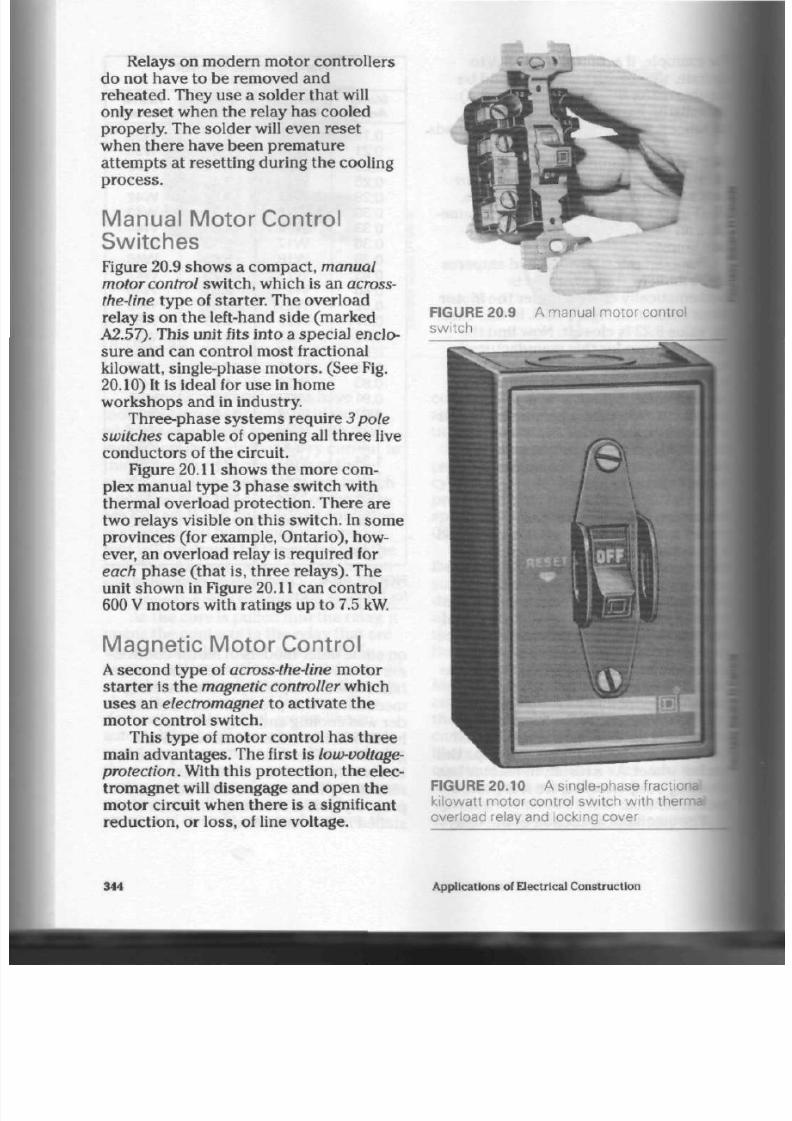
8/19/2019 Applications Electrical
http://slidepdf.com/reader/full/applications-electrical 349/447
Relays on modern motor controllers
do not have to be removed and
rehea ted. They use a solder that will
only reset when the relay has cooled
properly. The sold er will even rese t
when there have been prem ature
attempts at resetting during the cooling
process.
Manual Motor Control
Switches
Figure 20.9 show s a com pac t,
manual
motor control
switch, which is an
across-
the-Iine
type of starter. The overload
relay is on th e left-hand side (mark ed
A2.57). Th is unit fits into a s pec ial en clo
sure and can control most fractional
kilowatt, single-phase m oto rs. (See Fig.
20.10) It is ideal for use in home
workshops and in industry.
Three-phase systems require
3 pole
switches
cap ab le of opening all th re e live
con du ctors of the circuit.
Figure
20.11
shows the more com
plex manual typ e 3 ph ase switch with
thermal overload protection. There are
two relays visible on this switch. In some
provinces (for example, Ontario), how
ever, an ov erload relay is required for
each
p ha se (that is, three relays). The
unit shown in Figure
20.11
can control
600
V
m oto rs with ra tings up to 7.5 kW.
Magnetic Motor Control
A secon d type of
across-the-line
motor
starte r is th e
magnetic controller
which
uses an
electromagnet
to activate the
motor control switch.
This typ e of motor con trol has three
main advantages. The first is low-voltage-
protection.
W ith this pro tection, th e elec
troma gnet will disengage and open th e
m oto r circuit wh en the re is a significant
redu ction , o r loss, of line voltage .
FIGURE 20.9
switch
-
A m anual motor control
FIGURE 20.10 A single-phase fractional
kilowatt motor control switch with therr
overload relay and locking cover
344
Applications of Electrical Construction
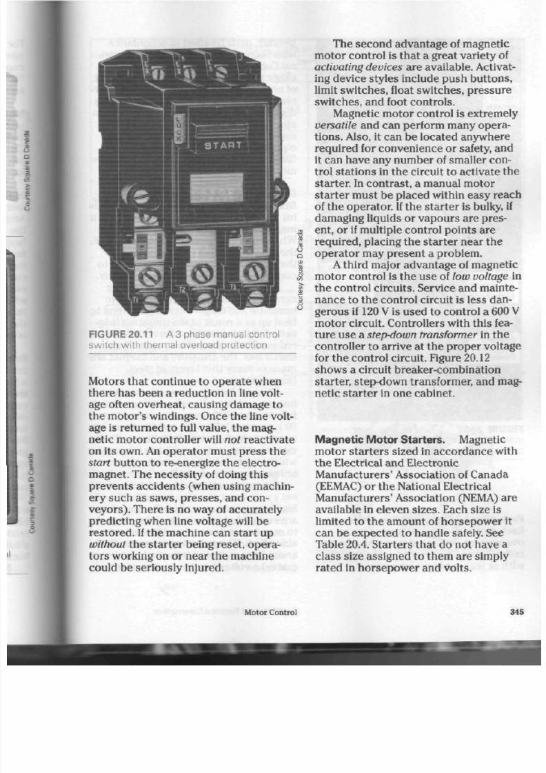
8/19/2019 Applications Electrical
http://slidepdf.com/reader/full/applications-electrical 350/447
u
a
o
FIGURE 20.11 A 3 phase manual control
switch with thermal overload protection
Motors that continue to ope rate when
there has been a reduction in line volt
age often o verheat, causing dam age t o
the m otor's w indings. Once the line volt
age is returne d t o full value, the m ag
netic motor controller will
not
reactivate
on its own. An op erato r mu st pres s t he
start
button to
re-energize
the electro
magn et. The nece ssity of doing this
prevents accidents (when using machin
ery such as saws, presses, and con
veyo rs). Th ere is no way of accurately
pred icting whe n line voltage will be
restored . If the m achine can sta rt up
without
the starter being reset, opera
tors working on or near the machine
could be seriously injured.
The second advantage of magnetic
motor control is that a great variety of
activating devices are available. Activat
ing device styles include push butto ns,
limit switches, float switches, pressure
switche s, and foot con trols.
Magnetic motor control is extremely
versatile
and can perform many opera
tions . Also, it can be loc ated anyw here
required for convenience or safety, and
it can have any n um ber of smaller con
trol stations in the circuit to activate the
starter. In con trast, a man ual m otor
starter must be placed within easy reach
of the operator. If the starter is bulky, if
damaging liquids or vapo urs are pres
ent, or if multiple control points are
required, placing the starter near the
operato r m ay present a problem.
A
third major advantage of magnetic
mo tor con trol is the use of
low voltage
in
the co ntrol circuits. Service and m ainte
nan ce to th e control circuit is less dan
gerous if 120
V
is used to co ntrol a 600
V
motor circuit. Controllers with this fea
ture use a
step-down transformer
in th e
controller to arrive at the prop er voltage
for the control circuit. Figure 20.12
show s a circuit b reaker-comb ination
starter,
step-down
transformer, and mag
netic start er in one cabinet.
Magnetic Motor Starters. Magnetic
motor starters sized in accordance with
the Electrical and Electronic
Manufacturers' Association of Canada
(EEMAC) or t he National Electrical
M anufactu rers' A ssociation (NEMA) are
available in eleven siz es. Each size
is
limited to the am ount of horse pow er it
can be exp ected to han dle safely. See
Table 20.4. Sta rter s tha t d o not ha ve a
class size assigned to them are simply
rated in horsepower and volts.
Motor Control
34

8/19/2019 Applications Electrical
http://slidepdf.com/reader/full/applications-electrical 351/447
FIGURE 20.12 Typical breaker-combination
starter, type 1, in a size 2 en closu re. (Door
removed for photograph.)
P rotection by Disconnecting Uni ts.
Each mo tor must be protected by an
overcurrent device such as a fuse or cir
cuit breaker. The disconnecting switch,
with or witho ut fuses, or a circuit
breaker, must be sized in accordance
with Section 28 of th e Canad ian Electi
cal Code. The disconn ecting unit for a
single mo tor m ust have a current rati
of not les s than
115%
of the full-load c
rent rating of the motor it controls.'
disconnecting unit must be able to
i
and close the circuit safely, without
exposing the o pera tor or surrounc
equipment to danger from arcing or
flashing. C hapter 17 explains this i
more fully.
Operation of the Magnetic Motor
Starter. There are three basic
i
for opening and closing the contac
ma gnetic m oto r starte r. (See Fig.
When current is passe d through thi
the
magnet
attracts the
armature
the moveable contacts are brought
connection with the stationary cc
The pulsating effect of alternat
current causes several problems,
armature and magnet assemblies ti
heat up as a re sult of the pulsati
netic field aro und th e m ain coil. To
red uce th is h eating effect, called I
teresis loss, the a rma ture and ma
m ade of many thin lay ers of steel
(laminations}.
The coil loses its strength for;
instant each time the alternating <
falls to zero (120 time s pe r sec ond i
60 Hz syste m ). Damage results:
the
con stant, high-speed attraction and
release of the a rm atur e by th e ma
which can be h eard a s an annoying
or hum from the controller.
Extensive wear and heat on tl
net 's
pole faces
can also be
exp
Small co pp er rings, called
shading
are embedded in the face of the:
to coun teract a nd red uce this unc
able effect. The pulsating magnetic I
around the main coil induces (gen
erates ) a voltage and curre nt in the
346 App lications of Electrical Con struction
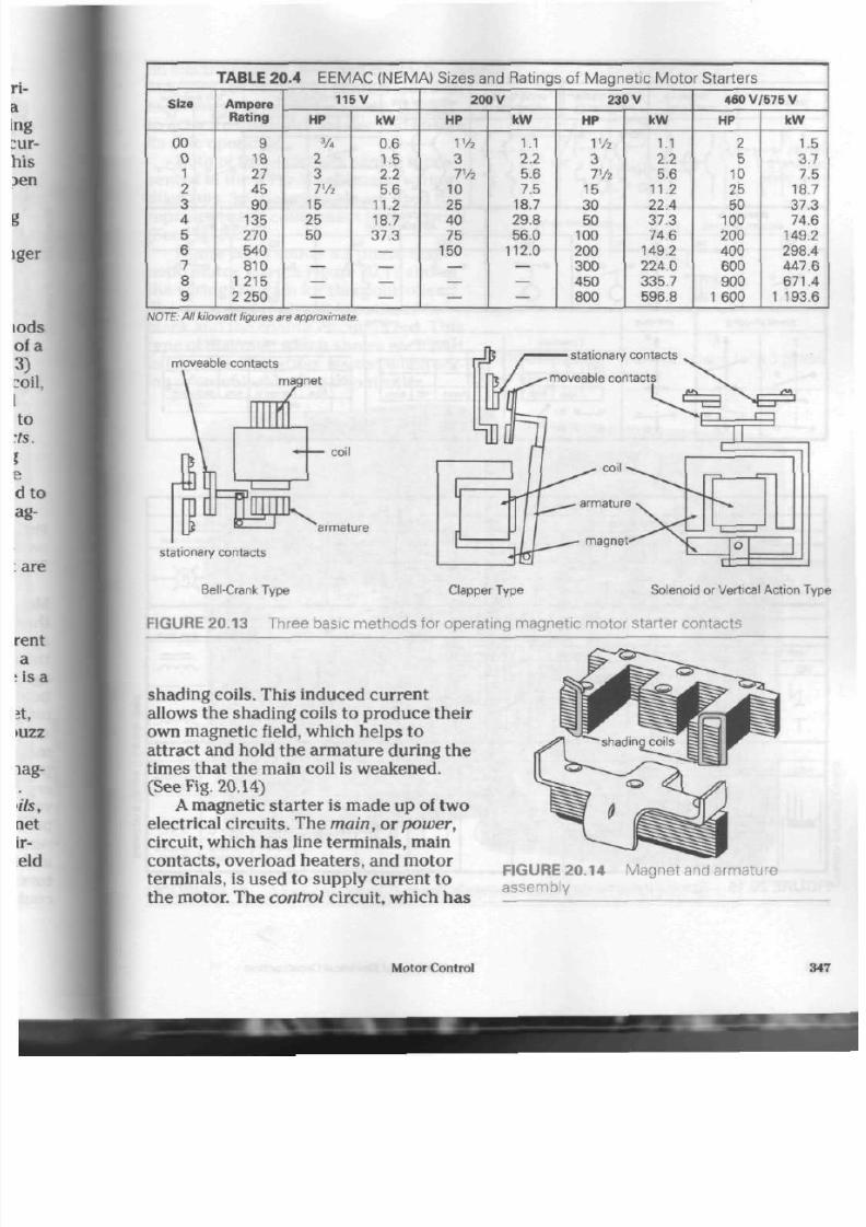
8/19/2019 Applications Electrical
http://slidepdf.com/reader/full/applications-electrical 352/447
TABLE 20.4 E E M A C ( N E M A ) S ize s and Rat ings of Ma gnet ic Mot o r S t ar ters
Size
00
0
1
2
3
4
5
6
7
8
9
Ampere
Rating
9
18
27
45
90
135
270
540
810
1 215
2 250
115V
HP
3
A
2
3
Th
15
25
50
kW
0.6
1.5
2.2
5.6
11.2
18.7
37.3
200 V
HP
Vh
3
Th
10
25
40
75
150
kW
I.'
2.2
5.6
7.5
18.7
29.8
56.0
112.0
230 V
HP
Vh
3
Th
15
30
50
100
200
300
450
800
kW
1.1
2.2
5.6
11.2
22.4
37.3
74.6
149.2
224.0
335.7
596.8
460 V /575 V
HP
2
5
10
25
50
100
200
400
600
900
1
600
kW
1.5
3.7
7.5
18.7
37.3
74.6
149.2
298.4
447.6
671.4
1
193.6
NOTE:
All kilowatt figures are
approximate.
moveable contacts
magnet
•
1 1
•
;
1
s
j r ^
.J
v
coil
armature
stationary contacts
Bell-Crank Type Clapper Type Solenoid or Vertical A ction Typ
FIGURE 20.13 Three basic methods for operating magnetic motor starter contacts
shading coils. This induced current
allows the shading coils to produce their
own magnetic field, which helps to
attract and hold the armature during the
times that the main coil is weakened.
(See Fig. 20.14)
A
magnetic star ter is made up of two
electrical circuits. The main, or power,
circuit, which has line terminals, main
contacts, overload heaters, and motor
terminals, is used to supply current to
the
motor.
The control circuit, which has
FIGURE 20.14
a s s e m b l y
Magnet and armat ure
Motor C ontrol
34
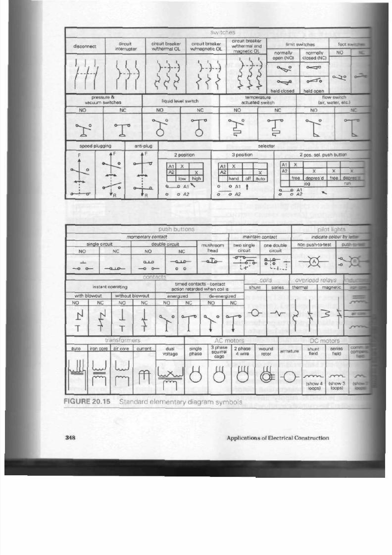
8/19/2019 Applications Electrical
http://slidepdf.com/reader/full/applications-electrical 353/447
switches
disconnect
circuit
interrupter
i i i
> • > • )
circuit breaker
w A h e r m a l OL
V - V - )
circuit breaker
w / m a g n e t i c OL
V ) - - )
circuit breaker
w A h e r m a l
and
magnet ic
OL
}-})
l imi t swi tches
normally
open (NO)
°^
°==r°
held closed
normally
closed (NCI
O^CTtJ
o
held open
pen
loot
s-. • •
N O
cvCjo
pressure
&
vacuum swi tches
l iquid level switch
temperature
actuated swi tch
f low swi tch
lair, water, etc.)
N O
N C
N O
NC
N O
N C
N O
N C
Y T
Y T
•> • °-p
T
^
speed plugging
anti-plug selector
*F 2 position
A '
A 2
X
low
X
high
nr
0 _ * A 1 ^
o o A2
3 position
A1
A 2
X
hand
off
X
auto
o o A1 t
o o A2
2 pos. sel . push but ton
Al
A 2
X
free
X
depres ' d
log
X
free
X
3 e : ; :
run
_D A1
o A2
push buttons
pilot lights
mom entary contact main ta in contact
indicate colour by i
single circuit
N O
N C
double circuit
N O
N C
contacts
m u s h r o o m
head
two s ing le
circuit
.-T
one double
circuit
non push-to-test
o | o T
-®-
Qj$- : - s
* &
instant operating
w i t h b l o w o u t
N O
i f
T
N C
wi thout b lowout
N O
1
T
N C
t imed contacts - contact
act ion re tarded whe n coil is
energized
N O
N C
T
de-energized
N O N C
Q—r—O
shunt
o
overload relays
thermal
*
magnetic
transformers
AC motors
DC motors
LE u
n
u
n
m
dual
voltage
single
phase
LxJ
n
6
3 phase
squirrel
cage
2 phase
4 wire
0
w o u n d
rotor
o
shunt
field
( s h o w 4
loops)
series
field
( s h o w 3
loops)
s-r
FIGURE 20.15 Standard elementary diagram symbols
348 Applications of Electrical Construction

8/19/2019 Applications Electrical
http://slidepdf.com/reader/full/applications-electrical 354/447
an electromagnet, overload contacts,
auxiliary (or maintain) conta cts, and an
asso rtm ent of control station s, is used
to activate the mo tor star ter and en sure
its safe o pera tion.
Both of the se circuits can b e repre
sented in the form of schematic wiring
diagram s. Special sym bols are used to
represent eac h com pone nt in th e circuit .
(See Fig. 20.15)
Figure 20.16 shows a 3 ph ase mag
netic motor starter. Figure 20.17 shows
the wiring diagram for this con troller.
The main power circuit is outlined in
black and th e control circuit in red . This
type of diagram, which show s each pa rt
in its correct location, is used when wir
ing or trouble sho oting a controller.
start
T
h
top
-
1
-
1
-
|
-
1
-
J
-
MC
i
Lm.
V
I
Ls
i
N O T E :
3 overload
heater units
9T2
9 T3
I
j 3 phase
V J motor
FIGURE 20.17 Wiring diagram for a 3 phase
magnetic motor starter
FIGURE 20.16 A self-contained, 3 phase magne tic mo tor starter (with pilot l ight)
Motor Control
349

8/19/2019 Applications Electrical
http://slidepdf.com/reader/full/applications-electrical 355/447
start
M
L i -
L 2 -
L 3-
stop
O L
3 Wire Control (momentary contact)
r,
C
MC
R X ,
l i 5 ^ _ j f 3 phase
. M C *
RXy
F I G U R E 2 0 . 1 8
S c h e m a t i c ( e l e m e n t a r y ) d i a
g r a m f o r a 3 p h a s e m a g n e t i c m o t o r s t a r t e r
Figure
20.18
shows an elementary
(schematic) diagram of the same con
troller. Although the parts are not in
their true locations, this type of diagram
gives an easily understood picture of the
circuit and is most helpful when trouble
shooting more complicated controller
types. When a complex control system is
to be developed, electricians often make
a schem atic diagram of the control
cir
cuit only. Figure 20.19 shows a variety of
the se diagrams.
Holding,
or M aintain,
Contacts
Magnetic motor s tarte rs must be able to
open the power circuit to a motor when
ever an overload relay indicates a dan
gerous condition, an under-voltage con
dition develops, or any form of control
switch indicates that operation of the
motor should be stopped .
To
do this,
most control stations use a set of start
con tacts that remain closed only as long
as the operator keeps a finger on th e
star t button. The moment the button is
released, a spring forces the contac ts
3 Wire Control (with pilot light)
stop
2 1 L '
3
® -
N O TE : Pilot light can be wired in parallel
wrtl
to show when starter energized ana
running.
3 Wire C ontrol (momentary contact
multiple push button station)
L i
start
1 stop stop stop
start
M O
"~20*
start
•MC
NO TE : Wh ere a motor must be started
and
from more than one location, any
i
start and stop push buttons may be i
together. Also, it is possible to
start/stop
station in combination w *
stop buttons at different locations
*
emergencies.
F I G U R E 2 0 . 1 9
S c h e m a t i c diagr
m o t o r c o n t r o l c i r c u i t s
350
Applications of Electrical Construction

8/19/2019 Applications Electrical
http://slidepdf.com/reader/full/applications-electrical 356/447
open again. This de-energizes th e coil in
the s tarter and al lows the m otor to stop.
A set of holding, or maintain, con
tacts are ei ther mounted on the same
contact carr ier bar as th e main po wer
circuit co nta cts or are activated by the
con tact carrier bar. Therefore, the main
tain contac ts open and close toge ther
with the main power circuit co nta cts.
They are electrically con nec ted in
parallel with the start button con tacts
and keep the coil energized on ce th e
start button has been released. Maintain
con tacts are represented by a normally
open contact (NO) sym bol in both sche
matic and wiring diagram s. Often, t he
letters MC will ap pe ar b eside the con
tacts to show that they are the maintain
contacts. (See Figs.
20.17
and 20.18)
Control Stat ions
Figure 20.16 show s a self-contained
mo tor controller with the sta rt /s top con
trol station m oun ted on the front of th e
unit. When there is to be mu ltiple-point
control, a remote push-button station is
used. Other types of control stations are
available, such as limit sw itches to con
trol the up and dow n m ovem ent of an
electric door, float switches to control
th e level of liquid in a tank, and dual-
action pu mp control sw itches. (See Figs.
20.20,
20.21, 20.22 and 20.23)
Sometimes it is nec essa ry to by-pass
the automatic control device and oper
ate th e con troller m anu ally to fill a tan k
or start a pump .
A
push button stat ion
with a selecto r switch is used with th e
controller to provide both manual and
automatic
co ntro l func tions. (See Fig.
20.24)
Occasionally, an ope rato r wishes to
control th e length of time a m otor
op era tes or th e length of time before a
seco nd control circuit is energized. A
FIGURE 20.20 A remote push button start/
stop control station
timing controller
is used for this p urp ose
(See Fig. 20.25) To calibr ate th e time
cycle, an a djusting screw at the top of the
unit regulates air (or oil) flow in and out
of a compression chamber. T his typ e of
con trol de vice is useful in redu ced volt
age starting un its for large m oto rs.
As me ntioned earlier, regulations
require three overload relays (one per
ph ase ) on a 3 ph ase m otor controller.
(See Fig. 20.26, page 354.) The reaso n
why is tha t a 3 ph ase m otor will con
t inue to ope rate o n any two of i ts th ree
phases if one should fail. It will not res
tart on two p has es, but if one p ha se is
disconnected, it can handle approxi
ma tely half of its rate d power.
A
motor
tha t is putting ou t less than its rated
pow er will soon hea t up from t he over
load, and its windings will be d am aged if
it is not d isco nn ec ted from th e line. An
overload relay on each ph ase ensures
Motor
Control
35
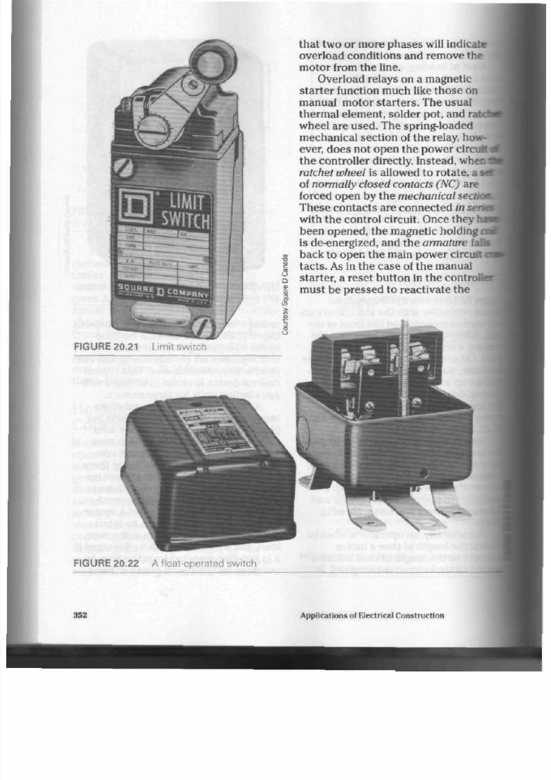
8/19/2019 Applications Electrical
http://slidepdf.com/reader/full/applications-electrical 357/447
FIGURE 20.21 Limit switch
o
a
that two or more phases will indicate
overload conditions and remove the
motor from the line.
Overload relays on a magnetic
star ter function much like those on
manual motor starters. The usual
thermal element, solder pot, and ratd
wheel are used. The spring-loaded
mechanical section of the relay, how
ever, does not open the power circuit <
the controller directly. Instead, when
ratchet wheel is allowed to rotate, a sa
of normally closed contacts (NC) are
forced open by the mechanical sea
These contac ts are connected in sene
with the control circuit. Once they ha
been opened, th e magnetic holding a
is de-energized, and the armature fa
back to open the main power circuit
<
tacts.
As
in the case of the manual
starter, a reset button in the contr
must be pressed to reactivate the
FIGURE 20.22 A f loat-operated switch
352 Applications of Electrical Cons truction
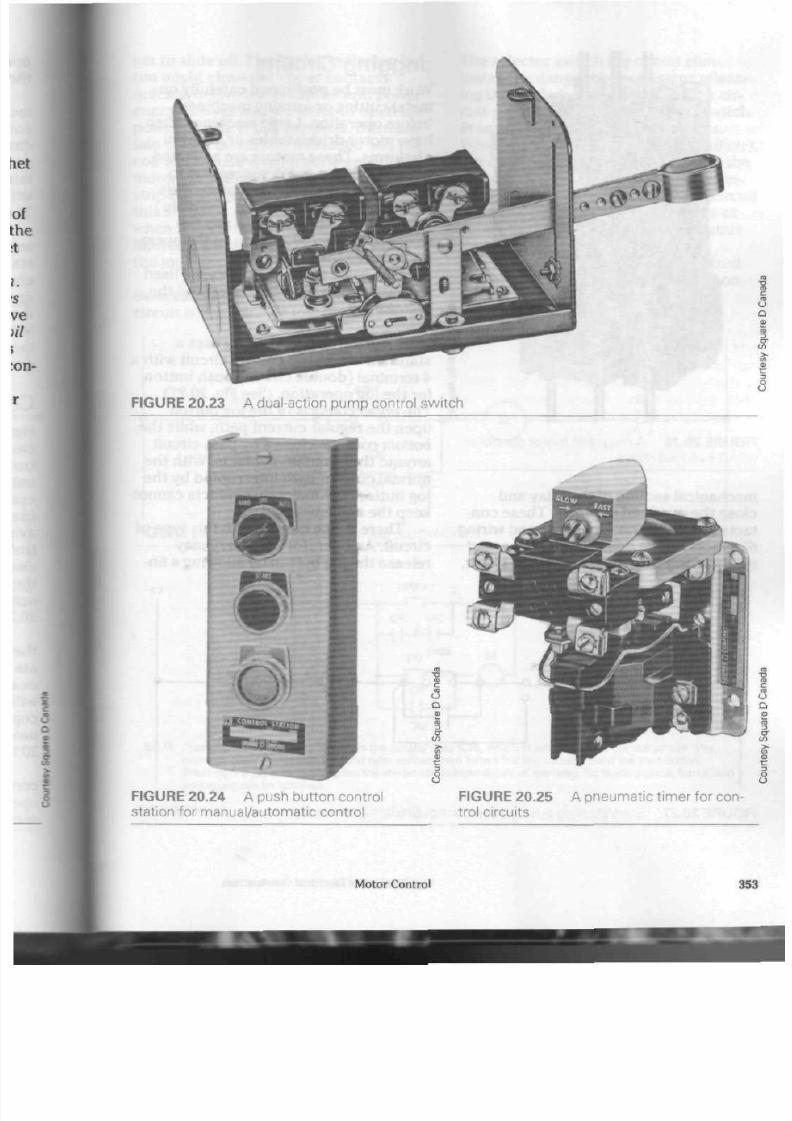
8/19/2019 Applications Electrical
http://slidepdf.com/reader/full/applications-electrical 358/447
FIGURE 20.23 A dual-action pum p control sw itch
**
I «®
* f t
o
a
1
s
O
U
FIGURE 20.24 A push button control
station for manual/automatic control
FIGURE 20.25
trol circuits
A pneumatic t imer for con-
Motor Control
35

8/19/2019 Applications Electrical
http://slidepdf.com/reader/full/applications-electrical 359/447

8/19/2019 Applications Electrical
http://slidepdf.com/reader/full/applications-electrical 360/447
ger to slide off. Th e spring in th e jog bu t
ton might close the upp er con tacts
quickly, before the arm atu re and pow er
contac ts have had a chan ce to open th e
pow er circuit. If this h app en s, th e main
tain contacts will still be closed and the
coil will rem ain energ ized, keep ing t h e
mo tor operating. To stop th e motor, the
stop button
must
be pressed. Although
this situation doe s not hap pen often,
when i t do es, the ope rator can be
injured if the m oto r fails to st op wh en
the jog button is released.
Selector Jog . A safer form of jogging
circuit is th e se lec tor jog. (See Fig. 20.28)
The selector switch jog circuit elim
inates the dan ger of an op erato r releas
ing the jog bu tton to o quickly. This cir
cuit places a single-pole selector switch
in series with the maintain contacts.
When th e switch is closed (run position)
th e circuit opera tes normally. When t he
switch is open
(jog position),
the main
tain co ntac ts cann ot k eep the coil circuit
energized. The pow er circuit opens as
soo n as th e opera tor releases the start
button.
As well, the re are m ore specialized
jogging circuits tha t m ake use of a con
tro l relay. (See Fig. 20.29)
If a motor circuit is to be jogged
L 2
O L
-M -
FIGURE 20.28 S tart/stop/selector jog con trol circuit
N O T E :
Pressing the start button energizes the control relay (CR), which in turn energizes the starter coil. The
normally open starter interlock and relay contact then form a holding circuit around the start button.
Pressing the jog button energizes the starter coil independently of the relay. No holding circuit forms, and
so jogging can be obtained.
FIGURE 20.29 Jog circuit with control relay
Motor Control 355
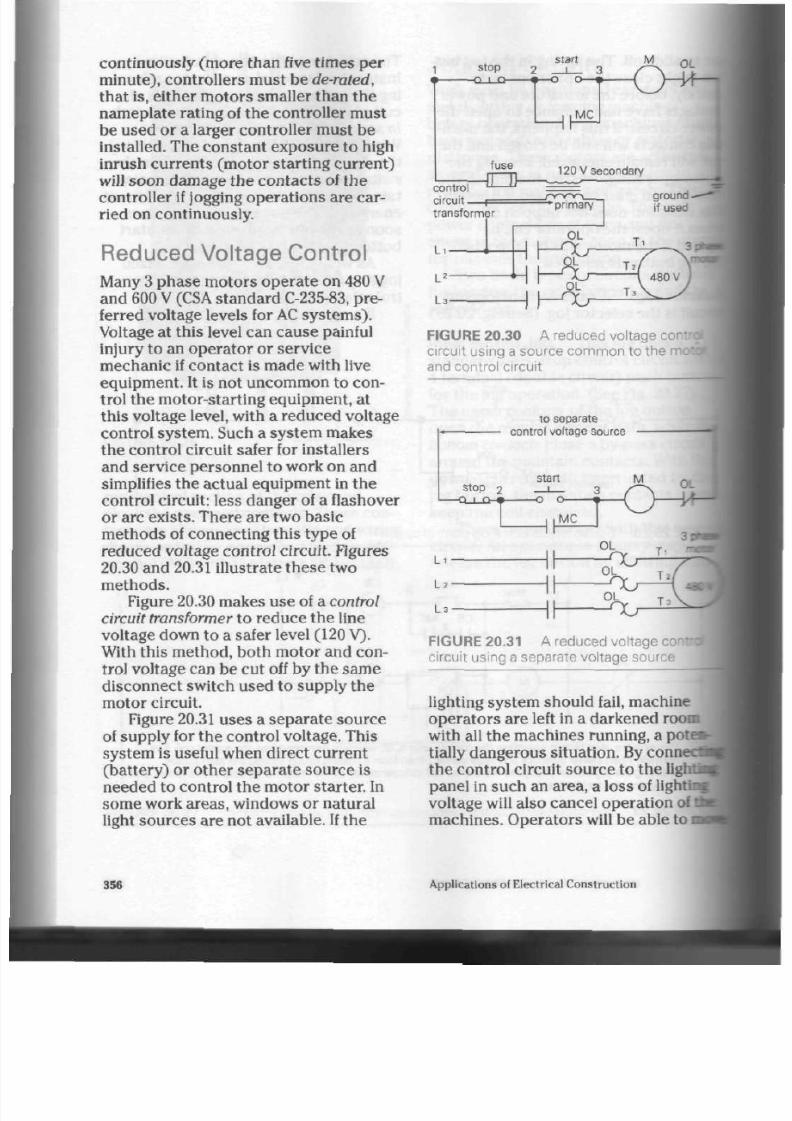
8/19/2019 Applications Electrical
http://slidepdf.com/reader/full/applications-electrical 361/447
continuously (m ore than five time s p er
minute), controllers must be de-rated,
that is, either moto rs smaller than th e
nam eplate rating of the controller mu st
be used or a larger controller must be
installed. The cons tant expo sure to high
inrush currents (motor starting current)
will soon d am age the con tac ts of th e
controller if jogging opera tion s are car
ried on continuously.
Reduced Voltage Control
Many
3
phase m otors ope rate on 480
V
and 600 V (CSA stan dar d C-235-83, pre
ferred voltage levels for AC system s).
Voltage at this level can cause painful
injury to an opera tor or service
m echa nic if con tact is m ade with live
equipm ent. It is not uncom mon to con
trol the m otor-starting equipm ent, at
this voltage level, with a redu ced voltage
control system. Such a system makes
th e contro l circuit safer for installers
and service person nel to work on and
simplifies the actual equipment in the
control circuit: less danger of a flashover
or arc exists. There are tw o basic
me thods of connecting this type of
reduced voltage control circuit. Figures
20.30 and
20.31
illustrate the se tw o
methods.
Figure 20.30 makes u se of a control
circuit transformer
to red uce th e line
voltage down to a safer level (120 V).
With this method , both motor and con
trol voltage can be cut off by the same
disconnect sw itch used to supply the
motor circuit.
Figure 20.31 use s a sep ara te s ou rce
of supply for the control vo ltage. This
system is useful when direct current
(battery) or other separate source is
needed to control the motor starter. In
some work areas, windows or na tural
light sources are not available. If the
FIGURE 20.30 A reduced voltage com
circuit using a source com mo n to the i
and control circuit
to separate
control voltage source
FIGURE 20.31 A reduced voltage
circuit using a separate voltage source
lighting system should fail, machine
op era tor s are left in a darken ed room
with all the machines running, a pote
tially dangerous situation. By conn
the control circuit sourc e to the
li
panel in such an area, a loss of ligh
voltage will also can cel o pera tion of
ma chines. O perato rs will be able to
356 Applications of Electrical Con struction

8/19/2019 Applications Electrical
http://slidepdf.com/reader/full/applications-electrical 362/447
abou t in the da rkened area m ore safely.
While only 480
V
and 600
V
were
men tioned at the star t of this se ction,
supply vo ltages of many levels can be
controlled by a reduced voltage system.
The higher the supp ly voltage, th e m ore
likely a control circuit using reduced
voltage will be requ ired.
Reversing Controllers
Interchanging an y two of the lea ds to a 3
ph ase m otor will cau se it to run in the
reverse direction. Single-phase m oto rs
tend to be mo re complicated and often
need connection changes within the
motor itself. For this rea son , only 3
phase controllers will be discussed in
this section.
A 3 ph ase reversing starte r consists
of
two contactors
enclosed in the same
cab inet. Only one set of overload relays
is used , however, since bo th forward
and reve rse control circuits are intercon
nected.
W hen rev ersing a motor, it is vital
that both contactors
not
b e energized at
the same time. Activating both co ntac tors
would ca use a sho rt circuit since two of
th e
line
condu ctors are reversed on one
con tactor. Preventing a sho rt circuit
from this ca us e is called interlocking.
Mechanical and electrical interlocking
sys tem s are available in m ost reversing
controllers.
The
mechanical
interlock u ses a sys
tem of levers to prevent the armature
of
th e reversing co ntac tor from engaging
when the forward con tactor 's arm ature
is in opera tion . Figure 20.32 sho ws a
schem atic diagram of the control circuit
for this type of unit.
The
electrical
interlock makes use of
two double-contact (4 terminal) push
bu ttons . When the forward bu tton is
pressed, the upper contacts open the
rev erse coil circuit. Even if the rev erse
coil is energized, th e c ontro l circuit will
be broken. The pow er circuit is opened
as soon as the forward button is
pre sse d. (See Fig. 20.33)
The electrical interlock circuit allows
the mo tor to be reversed simply by
pressing the reverse button. The
mechanical interlock system requires
that th e stop button be pressed. When it
Li
forward
stop
-0 I
Q-
reverse
< = >
O L
MC
1.2
FIGURE 20.32 Mechanical interlock forward/reve rse/stop control circuit
Motor Control 35

8/19/2019 Applications Electrical
http://slidepdf.com/reader/full/applications-electrical 363/447
Li
stop I forward
-Q-J D -&
OL
FIGU RE 20.33 E lectr ical inter lock forw ard /rev erse /s top contro l c i rcui t
Li
stop
jrward
J
^Hvic
•everse I
-o I o—I
xr
electricalt interlock
R 6
•it 1 •-
F
-Vh
f o r . k -
7
-• »-
O L
Yr
mit
switches (if used delete jumpers 6
and
i
F IGU R E 20. 34 S c hemat ic d iagram s ho w ing a rev ers ing c ont ro l c i rcu i t w i t h lim i t s w i t c h es
<
separate elect r ical inter lock contacts
is , th e forward co nta cto r will be disen
gaged before the reversing c on tacto r
can be brought into service.
Figure 20.34 shows a sche m atic dia
gram for a reversing con trol circuit util
izing limit switch es a nd electrical inter
lock contacts. Operation of either the
forward or reverse co ntac tors will open
the matching interlocking contac t. This
makes it unnecessary to press the stop
button before changing the motor's
direction of rotation.
Safety Note: Take care when revers
ing large mo tors . The s ud de n jar of
direct reversal can damage the machine
or equipm ent the m otor is driving. High
inrush currents can cause damage to
both the motor and the controller if
tt*
motor is reversed without allowing
enough time for the speed of the motor
to decrease.
Figure 20.35 shows a complete wir
diagram for a reversing controller.
Figure 20.36 show s an altern ate
con
trol circuit for such a controller sche
matically.
Multiple push-button stations can
1
used with the reversing controller. Fig
ure 20.37 shows a schematic diagram a
two forward/reverse/stop stations.
358
Applications of Electrical Co nstruction

8/19/2019 Applications Electrical
http://slidepdf.com/reader/full/applications-electrical 364/447
push button stations
forward
(for.)
reverse
(rev.)
* <S
r-
#
V
stop
i -
M C
L i
La
O L
contacts
f or )
coil
• r
L 3
1 .. ..
43<
O L heater
T3
N O TE : Power circuit in
black,
control circuit in red
maintain
contacts (MC)
J
FIGURE 20.35 C om plete wiring diagram of a 3 phase reversing controller
limit switches (if used)
N O TE : 3 wire control of a reversing starter is possible
with this forward/reverse/stop push button station.
Limit switches can be added to stop the motor at
a certain point in either direction. Jumpers from
terminal 6 and terminal 7 to the forward and reverse
coils must then be removed.
FIGURE 20.36 A lternate diagram of a
reversing control circuit (with limit switches)
stop stop I rev. rev for. for.
— o l n — o l r > — k i l o - o l n - , h l n - n l r^
maintain-
contacts
*8w
OL contacts '
FIGURE 20.37 S chematic diagram showing
multiple push button control for a reversing
starter
Motor Control
35
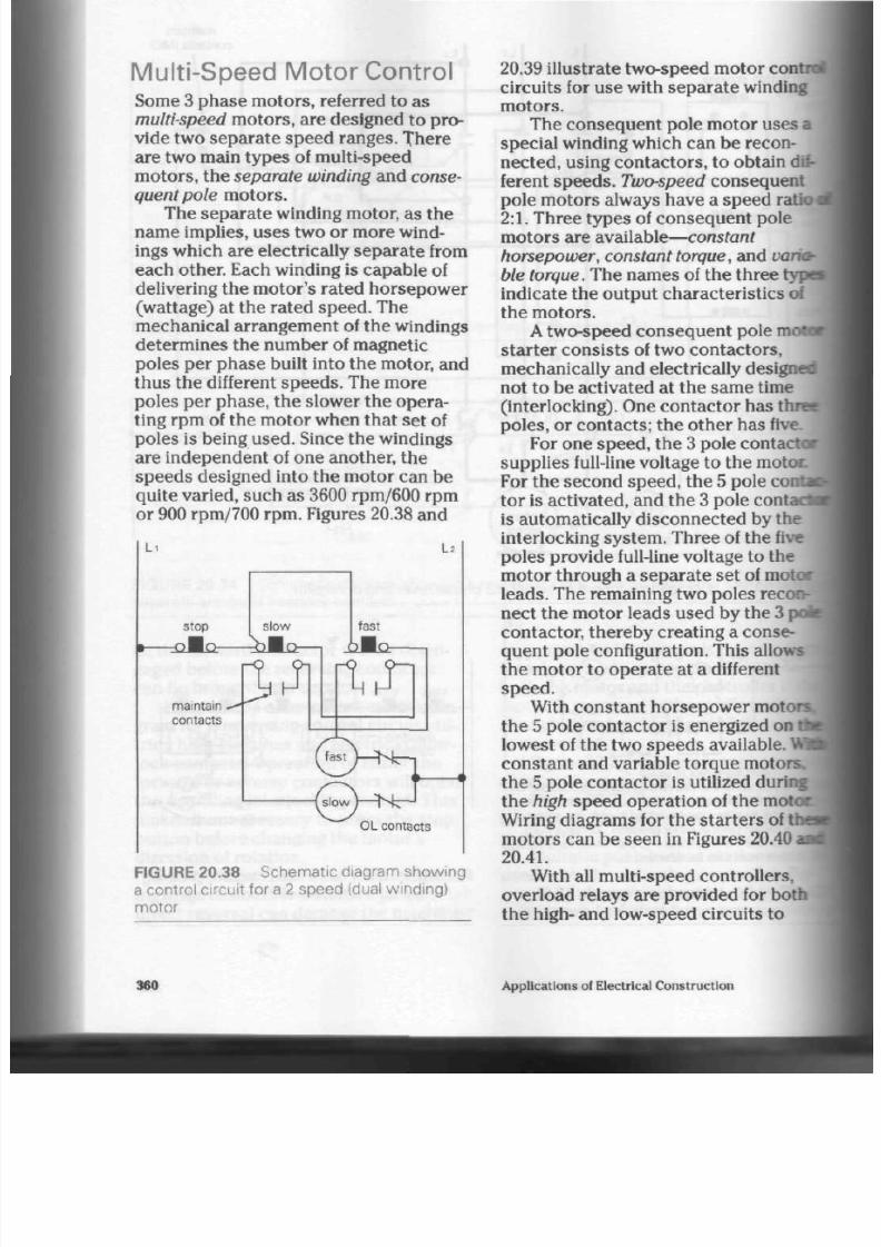
8/19/2019 Applications Electrical
http://slidepdf.com/reader/full/applications-electrical 365/447
Mult i -Speed Motor Control
Some 3 ph ase m oto rs, referred to as
multi-speed
moto rs, are designed to
pro
vide two sepa rate speed ranges. There
are two main types of multi-speed
motors, the
separate winding
and
conse
quent pole
motors.
The separate winding motor, as the
nam e implies, uses two or m ore wind
ings which are electrically separate from
eac h o ther. Each winding is cap able of
delivering the motor's rated horsepower
(wattage) at the rated speed. The
mechanical arrangem ent of the windings
determines the number of magnetic
poles per p hase built into the motor, and
thu s the different sp eed s. The m ore
poles per phase, the slower the opera
ting
rpm
of the motor when that set of
poles is being used. Since the windings
are indepen dent of one another, th e
speeds designed into the motor can be
quite varied, such a s 3600 rpm/600 rpm
or 900 rpm/700 rpm . Figures 20.38 and
Li
La
stop
slow
raBki—rhMo—i _QMQ:
fast
ru ftJl
OL contacts
FIGURE 20.38 S chematic diagram show ing
a control circuit for a 2 speed (dual winding)
motor
20.39 illu strate
two-speed
motor control
circuits for use with separate winding
motors.
The conseq uent pole motor uses a
special winding which can be recon
nected, using contac tors, to obtain dif
ferent speeds.
Two-speed
consequent
pole m otors always have a speed ra
2:1.
Th ree types of conseq uen t pole
motors are
available—constant
horsepower, con stant torque,
and
varia
ble torque.
The nam es of the th ree types
indicate the outp ut ch aracteris tics of
the m otors .
A two-speed
consequent pole
mo*
starter consists of two contactors,
mechanically and electrically designed
not to be activated at th e same time
(interlocking). One con tacto r ha s thre e
poles, or contacts; the other has
fivi
For one sp eed, the 3 pole
contacts
sup plies full-line v oltage to th e m otoc
For the sec ond spee d, th e 5 pole cor
tor is activa ted, and th e 3 pole conta
is automatically disconne cted by the
interlocking sy stem . Three of the five
poles provide full-line voltage to the
motor through a separate set of
mote
leads.
The remaining two poles recon
nect the motor leads used by the
31
contactor, there by creating a conse
quent pole configuration. This allows
the motor to operate at a different
speed.
With constant horsepo wer
motors,
the 5 pole con tactor is energized on
tta
lowest of the two speeds available.
Vfc^
constant and variable torque motors
the 5 pole conta cto r is utilized during
the
high
speed operation of the motoc
Wiring diagrams for the starters of the*
m oto rs can be seen in Figures 20.40 and
20.41.
With all multi-speed con trollers,
overload relays are provided for both
the high- and low-speed circuits to
360
Applications of Electrical C onstruction
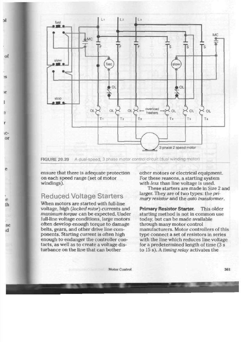
8/19/2019 Applications Electrical
http://slidepdf.com/reader/full/applications-electrical 366/447
fast
slow
_4_MC
L i
I ?
La
1
In
\
MC
OL OL
stop
I
Ti
^-ESS-i
T2 T3 T* Ts T
3 phase 2 speed motor
F I G U R E 2 0 . 3 9 A d u a l - s p e e d , 3 p h a s e m o t o r c o n t r o l c i r c u i t ( d u al w i n d i n g m o t o r )
ensure that there is adeq uate protect ion
on each spee d rang e (set of m otor
windings).
Reduced Voltage Starters
W hen mo tors a re start ed with full-line
voltage, high {locked rotor) curren ts and
maximum torque can be exp ected . Under
full-line v oltage co nd itions, large m oto rs
often develop enough torque to damage
belts, gears, and o the r drive line com
ponents. Starting current is often high
enough to endanger the controller con
tacts, as w ell as to c rea te a voltage dis
turban ce on the l ine that can bothe r
other motors or electrical equipment.
For these reasons, a starting system
with
less
than line voltage is used.
Th ese sta rte rs are ma de in Size 2 and
larger. Th ey are of two typ es: the pri
mary resistor and the auto transformer.
Primary Res istor Starter. This older
starting method is not in common use
today, but can be m ade available
through many m otor control
ma nufacturers. M otor controllers of this
type c onn ect a set of resistors in series
with the line which red uce s line voltage
for a pre de term ined length of time (3 s
to 15 s) . A timing relay activates the
Motor Control
36
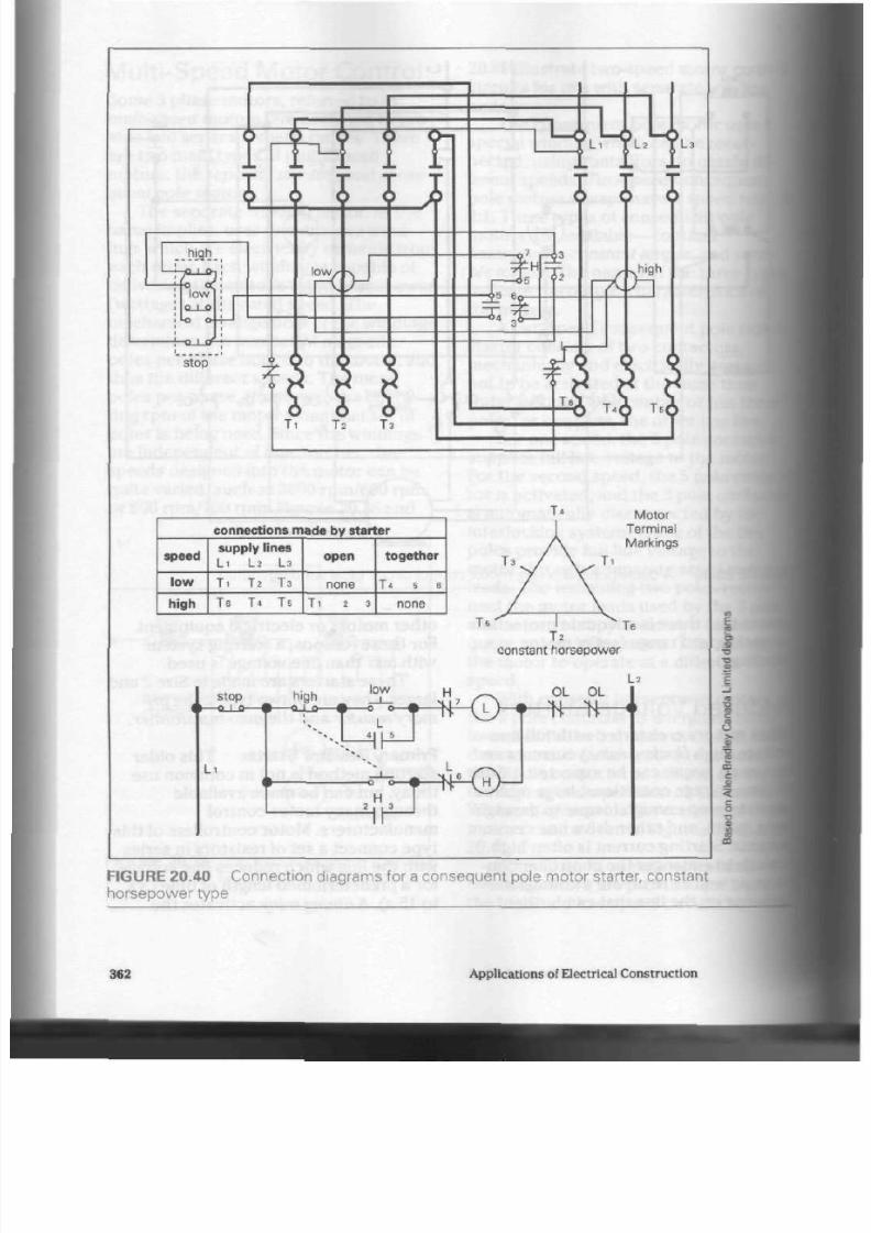
8/19/2019 Applications Electrical
http://slidepdf.com/reader/full/applications-electrical 367/447
:jf^F:^
i
hjgh _
rs
ow
Q_1_0
stop
0_i_J
I O W X N J
T I
T2 T 3
connections made by starter
speed
low
high
supply lines
L i L2 L3
T I
T2 T3
T e T 4 T s
open
none
T i
2 3
together
T l 6 6
none
Motor
Terminal
Markings
constant horsepower
stop
- Q _ | _ S -
L i
high
—o.
low
1_0 • 0 o — •
L
H
~s
H
2 i , 3
J
4K5^
OL
OL
L 2
5
—
FIGURE 20.40 Connection diagrams for a consequent pole motor starter, constant
horsepower type
3 62 Applications
of
Electrical Construction

8/19/2019 Applications Electrical
http://slidepdf.com/reader/full/applications-electrical 368/447
I
high
9
o.
low
l_l_0<
•-o o-
slop
I I I I
high
« >
T s
J 5 J
m
:2_
1-
L
low
X>n
T2A T
3
i
connections made by starter
speed
low
high
supply lines
L i
L 2
L s
T . T 2 T 3
Te
T*
Ts
open
T 4 5 6
none
together
none
T i
2 3
T2 Te
FIGURE 20.41 C onnection diagrams for a consequent pole motor starter, constant
torque or variable torque type
Motor Control
36
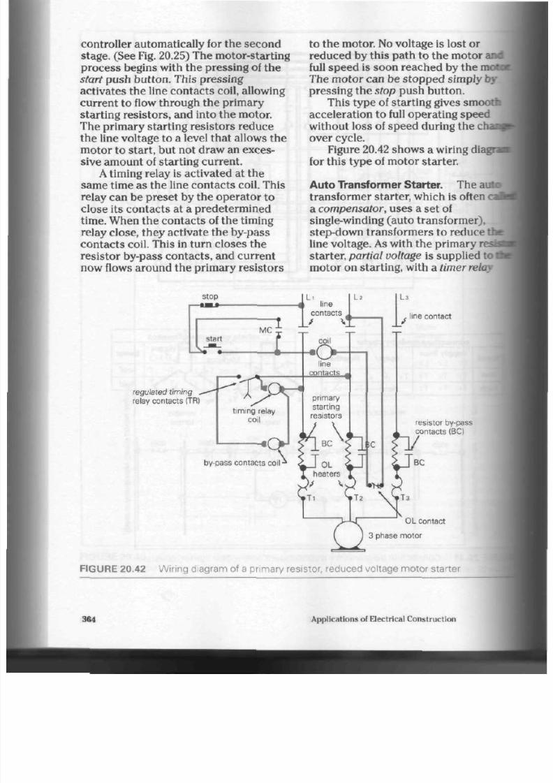
8/19/2019 Applications Electrical
http://slidepdf.com/reader/full/applications-electrical 369/447
controller automatically for the second
stage . (See Fig. 20.25) The m otor- starting
proc ess begins with the pressing of th e
start push button. This pressing
activates the line contacts coil, allowing
current to flow through the primary
starting resistors, and into the m otor.
The primary starting resistors reduce
the line voltage to a level that allows th e
mo tor to start, but not draw an exces
sive amo unt of starting c urrent.
A
timing relay is activated at t he
sam e time as th e line con tacts coil. This
relay can be preset by the opera tor to
close its contacts at a predetermined
time.
When the con tacts of the timing
relay close, the y activate the by-pass
con tacts coil. This in turn close s the
resistor by-pass contacts, and current
now flows around the prim ary resistors
to th e m otor. No voltage is lost or
reduced by this path to the motor
and
full speed is soon reached by the
moti
The m otor can b e stopped simply by
pressing th e stop push button.
This type of starting gives smooth
acceleration to full operating speed
without loss of speed during the
cr
over cycle.
Figure 20.42 show s a wiring di<
for this type of motor starter.
Au to Transformer Starter. The ai
transformer starter, which is often
i
a
compensator,
uses a set of
single-winding (auto transformer),
step-down transformers to reduce th
line voltage. As with th e p rima ry
i
starter,
partial voltage
is supplied to
mo tor on starting, with a timer relay
regulated timing
relay contacts
(TR)
line contact
resistor by-pass
contacts (BO
by-pass contacts coi
OL contact
3 phase motor
F IGU R E 20. 42 W i r ing d iagram of a pr imary res is tor , reduc ed v o l t age mot or s t ar t er
364
Applications of Electrical Construction

8/19/2019 Applications Electrical
http://slidepdf.com/reader/full/applications-electrical 370/447
calibrated to activate the start er's sec
ond stage.
The starting seq uen ce of this unit is
set in motion by the press ing of the start
push button. The pressing ac tivates
three electromechanical devices at the
sam e time:
a) The timing relay is set for its pred e
termined time and begins its count
down. The maintain contacts in thi s
controller are activated by the timing
relay and keep the control circuit
energized once the start button has
been released.
b) The
start contacts coil
is activated
and in turn clo ses the starting contacts
c) The transformer contacts coil is also
energized and closes th e transformer
contacts, allowing curent to flow into
the 3 pha se transforme r circuit (Wye
connected).
As can be see n in the wiring diagram,
Figure
20.43,
the starting contacts
receive their voltage and current from
approximately midpoint on the tran s
former. This starting vo ltage is about
65% of the full-line voltage available. It
can thus start the motor with a moder
ate am ount of starting current, while
preventing dangerous current surges.
stop
start
maintain contacts -
controlled by
timing relay
contacts
t imed
to open
contacts
t imed
to close
timing \
relay coil
=*—Q4
transformer \
contacts coil
_ H L
tart
contacts coil
run
^
contacts coil
L i
I?
L 3
IT
-run
contacts
"C
1.
,
IrM
i I I
Hi -
transformer
contacts
(T)
transforme
auto transformer
Wye connected
starting contacts
F I G U R E 2 0 . 4 3 T y p i c al a u t o t r a n s f o r m e r , r e d u c e d v o l t a g e m o t o r s t a r t e r d i a g r a m
Motor Control 365

8/19/2019 Applications Electrical
http://slidepdf.com/reader/full/applications-electrical 371/447
When the timing relay reach es the
end of its coun tdow n (5 s to 15 s), it
automatically opens the starting and
transformer con tac ts by de-energizing
the coils controlling th ose con tacts . At
the sam e time, the
run contacts coil
is
activated and the run contacts are
closed. Current is now allowed to travel
straight throu gh to the m otor instead of
detouring through th e transformer cir
cuit. Full-line volta ge is now applied to
the motor which soon reaches its full
operating speed. Operation can be
brought to a halt by pressing the stop
push button.
More starting torque is available with
this type of controller than with the pri
mary resistor type of unit. Starting
torque under reduced voltage condi
tions, however, is never eq ual to that
obtained when using full-line voltage.
When the commonly used 65% voltage
tap is connected for start-up of the
motor, the torqu e outpu t is reduced to
approximately
50%
of the tor qu e that
would be available if full-line voltage w as
used . This may be qu ite sufficient for
many applications, but high-inertia
loads,
such as large b all mills, may not
be able to use the reduc ed voltage,
starting-controllers due to the loss of
torque during the starting sequence. Use
of the
80%
tap on th e transform er will
provide about 75% torqu e, w hile th e 50%
transformer tap will reduce torque level
to approximately 30%.
Figure 20.43 show s this typ e of con
troller circu it.
To prevent th e current surge nor
mally occ urring as the co ntroller shifts
from partial to full-line voltage, some
manufacturers have produced a unit
with a different type of control circuit.
Operating Sequence for a Reduced
Voltage
Starter,
Closed Circuit Transition
(Fig. 20.44):
oil
rrr.iii«
to
a) Pressing the start button activates
the
IS
coil circuit. T his
IS
coil, in
turn, closes th e group of three IS
co nta cts located at the right-hand
side of the auto transformers in
tin
circuit diagram. This completes a
W ye connection in the transforraen
them selves. At the sam e time, the
I
(normally op en) co nta ct in the 2S
coil circuit is clo sed.
b) Closing th e 2S coil circuit a ctiv ate
the 2S (normally open ) contac ts
a
the left-hand side of the auto
transformers, feeding line voltage
into the transformers. The 2S coi
also closes the 2S con tacts
(no
open ) in the R coil circuit an d si
pair of
timed,
TR2S cont act s into
their timed sequence operation.
At this
point,
the motor starts on 65
of the full-line voltage.
c) After 5 s to 15 s, pr eset b y
either d
manufacturer or the installer, the
"timed-to-open" TR2S co ntacts
ope
the IS coil circuit, there by causing
the transformers '
IS
contacts to
drop open and deactivate the Wjn
connection.
d) Simultaneously, th e "timed-tc
TR2S conta cts ac tivate the
R
co
cuit. This in turn closes t he m ain
(Run) con tacts in the starter, si
ing full-line v oltage to th e m oto r i
perm itting it to reach ope rating
i
and torque .
e) The R coil also closes the R cor
circuit contact (which acts as a
i
tain contact) and opens the nor
closed R contacts in both the ISi
2S coil circuits . This cu ts power t
the transform ers while they are
•
the ru n mod e.
f) Pressing th e stop button will opee
Line 1 to the entire control circu
and allow the m otor to stop .
366
Applications of Electrical Construction

8/19/2019 Applications Electrical
http://slidepdf.com/reader/full/applications-electrical 372/447
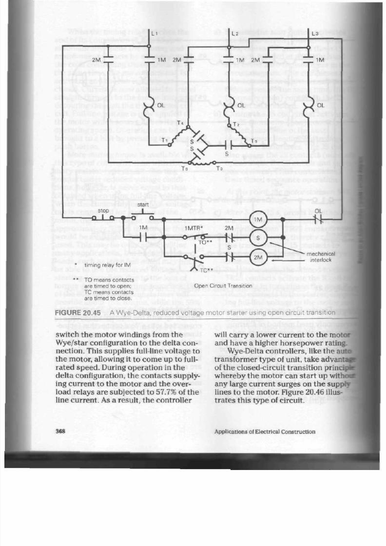
8/19/2019 Applications Electrical
http://slidepdf.com/reader/full/applications-electrical 373/447
t imin g relay for IM
TO means contacts
are timed to open;
TC means contacts
are timed to close.
• T C "
Open Circuit Transition
FIGURE 20.45 A Wye-D elta, reduced voltage mo tor starter using open circuit transition
switch the m otor windings from the
W ye/star configuration t o the de lta con
nec tion. Th is supp lies full-line vo ltage to
the mo tor, allowing it to com e u p to full-
rated speed. During operation in the
delta configuration, the contacts supply
ing current to the m otor and th e over
load relays are subjected to
57.7%
of t h e
line cu rrent. As a result, the controller
will carry a lower curren t to th e m otor
and have a higher horsepower rating.
Wye-Delta con trollers, like the auta
transformer type of unit, take advant
of the
closed-circuit
transitio n princ
whereby the mo tor can start up
witr
any large curre nt surg es on the supply
lines to t he motor. F igure 20.46 illus
tra tes th is type of circuit.
368
Applications of Electrical Construction
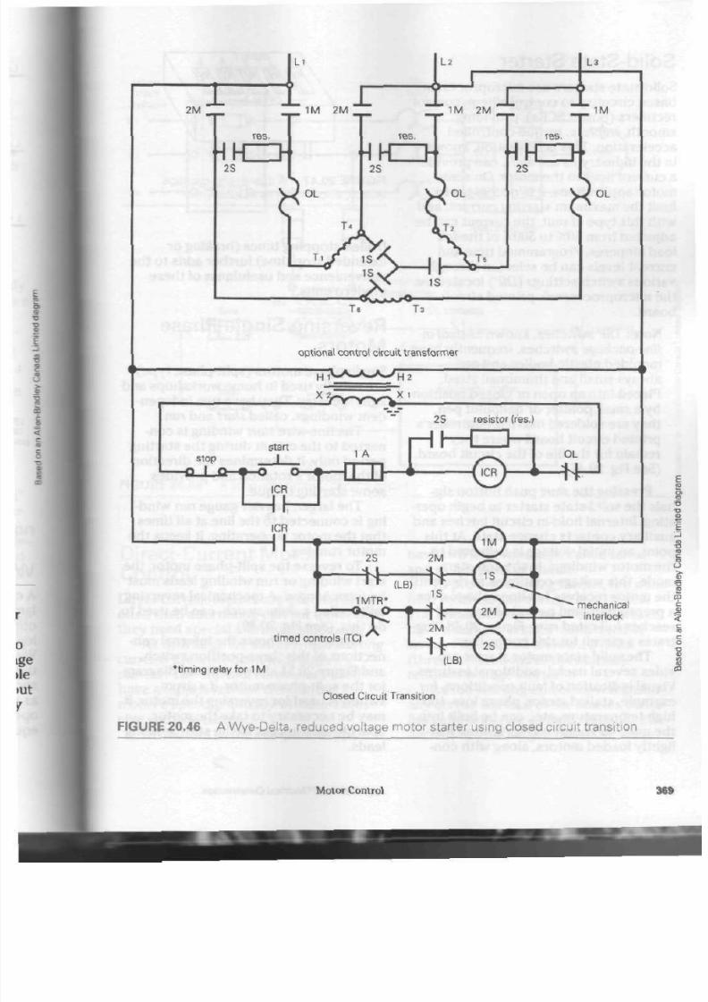
8/19/2019 Applications Electrical
http://slidepdf.com/reader/full/applications-electrical 374/447
mechanical
interlock
timed controls (TC)
"timing
relay for 1M
Closed Circuit Transition
FIGURE 20.46 A Wye -Delta, reduced voltage motor starter using closed circuit transition
Motor Control

8/19/2019 Applications Electrical
http://slidepdf.com/reader/full/applications-electrical 375/447
Solid-State S tarter
Solid-state starters use microprocessor-
based circuitry to control silicon control
rectifiers (power SCRs), providing
smooth, stepless, torque-controlled
acceleration. This acceleration, known
in the indu stry as
soft
start,
can provide
a curre nt limit to th e motor. On som e
mo tor applications, it is nec essa ry t o
limit the maximum starting current, and
with this type of unit, the current can be
adjusted from 50% to 500% of th e full
load am peres. Programmed time and
current levels can be selected throug h
various sw itch settings {DIP) located on
the microprocessor's printed circuit
board.
Note:
DIP sw itche s, known as
dual-in
line-package switches, frequently have
moulded plastic bodies and are
always small and thumbnail sized.
Placed into an open or closed position
by a small pointer o r ballpoint pen ,
they are soldered into the controller's
printed circuit board where they
remain for the life of the circuit board.
(See Fig. 20.47)
Pressing the
start
push button sig
nals the
solid-state
starter t o begin oper
ating. Internal hold-in circuit la tche s an d
auxiliary co ntac ts ch ange sta te. At this
point, an initial voltage is d elivered,to
th e m oto r windings. In the soft-start
mod e, this voltage continu es to rise until
the motor receives full-line voltage over
a preprogram med period of time and
rea ch es full-rated rpm . Figure 20.48 illus
tra tes a circuit for this controller.
The solid-state m otor star ter p ro
vides several useful, additional features.
Visual indication of fault conditions, for
example, stalled m otor, phase loss, too
high temperature, etc., can be built into
the unit. An energy-saving feature for
lightly loaded m oto rs, along with con-
u u u u u
FIGURE 20.47
A dual-in-line-package
switch,
also kno wn as a DIP switch
trolled stopp ing times (braking or
extend ed sto p time) further ad ds to
th
convenience and usefulness of these
mod ern units.
Reversing Single-Phase
Motors
Single-phase motors (split-phase ty
are usually used in hom e workshops a
light industry. They have two indepen
de nt w indings, called start a nd run.
The fine-wire start winding is con
nected to the circuit during the
startup
period only. It determines the directia
of the motor's rotation and provides
some starting torque.
The larger, heavier gauge
run
wind
ing is conn ecte d t o th e line at all times
that t he motor is operating. It keeps tin
motor running.
To reverse the split-phase motor,
start winding or run winding leads
be interchanged. A m echanical reve
unit, called a
drum switch,
can be
usee
do this. (See Fig. 20.49)
Figure 20.50 shows th e internal co«
nections of this
three-position
switch,
and Figure 20.51 sho w s a wiring diagn
for th e split-p hase mo tor. If a drum
switch is used for reversing the mot
may be nece ssary to take the motor
apa rt to gain access to the s tart win
leads.
370
App lications of Electrical Construction
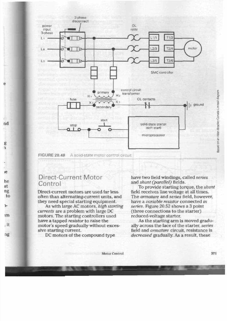
8/19/2019 Applications Electrical
http://slidepdf.com/reader/full/applications-electrical 376/447
3 phase
disconnect
power
input
3-phase
SMC controller
fuse
H
primary
H J
control circuit
transformer
stop
- Q j _ 0 -
x?r~yv~Y-'i
* secondary
start
X .
OL contacts
—Nr-
solid-state starter
(soft start)
microprocessor
> 11
ground
FIGURE 20.48 A solid-state motor control circuit
Direct-Current Motor
Control
Direct-current mo tors a re used far less
often than alternating-current units, and
they need special starting equipment.
As with large AC m otors, high starting
currents
are a prob lem with large DC
mo tors. The start ing controllers used
have a tapped resistor to raise the
motor's speed gradually without exces
sive starting curren t.
DC motors of the compo und type
hav e tw o field winding s, called series
and shu nt (parallel) fields.
To provide starting torque , the shunt
field rece ives line voltage a t all time s.
The armature and series field, however,
have a va riable resistor connected in
series. Figure 20.52 show s a 3 point
( three connections to the starte r)
reduced-voltage starter.
As the startin g arm is moved gradu
ally across the face of the starter, series
field and armature circuit, resistance is
decreased gradually. As a result, th es e
Motor Control
371

8/19/2019 Applications Electrical
http://slidepdf.com/reader/full/applications-electrical 377/447
F I G U R E 2 0 . 4 9 A 3 position—reversing, c
a nd forward—drum s w i t c h , w i t h t he c ov er
r e m o v e d
starting
resistance
starting arm
L i -
reverse
3 C - ^ 4
50 0 6
handle end
of*
1 0
3 0
5 0
0 2
0 4
0 6
for.-.
36
6 4
5 0 — O i l
FIGU R E 20. 50 In t erna l c onne c t ions f or
pos i t ion rev ers ing drum s w i t c h
motor
F IGU R E 20. 51 W i r ing d iagram s how i r
a spl i t -phase motor (wi th drum swi tch)
revers ing
holding coil
to disconnect
L 2 *
FIGU RE 20.52 Typical 3 point man ual DC mo tor s tarter
372
Applications of Electrical Construction

8/19/2019 Applications Electrical
http://slidepdf.com/reader/full/applications-electrical 378/447
windings are exposed to m ore and more
voltage, until full op eratin g spe ed is
reached. A holding coil keep s the start
ing arm in the ru n position until the
ope rator re turns it to the off position.
If the shunt field circuit is opened or
dam aged in any way, th e h olding coil,
which is conn ected in series with the
shunt field, releases the spring-loaded
startin g arm and th e m otor s hu ts off.
This no-field-release protection is very
imp ortant for DC m oto rs. Without it, an
extremely dangerou s spe ed will be
reached quickly if the shunt field is
disconnec ted. Large
DC
motors can
speed up to the point at which the arma
ture windings are thrown out of their
retainers (by centrifugal force) and the
motor destroyed. The direct-current
controller can be used to regulate the
starting of a shunt motor, which has no
series field, by placing the A2 side of the
arma ture directly on the arm ature termi
nal of the controller.
Figure 20.53 shows the wiring for a
second type of manual motor starter, th e
4 point (four connections to the starter)
motor starter. These controllers provide
no-voltage-protection , which prevents th
motor from restarting by itself if a power
failure has caused the holding coil to
release the starting arm.
Successful sta rting of th e m otor w ith
a manual starter depends entirely on the
operator. If th e starting arm is moved
too quickly, strong inru sh cu rren ts will
damage the controller and/or th e motor.
An automatic m otor starter to prevent
such hum an erro r is available. The oper
ator simply press es a start button,
which in turn activates a solenoid
(electromagnet). The solenoid is anoth er
form of timer relay, which controls th e
speed at which th e conta cts of the con
troller close . Closing of th e co nta cts grad
ually eliminates the starting resistance
and the motor accelerates smoothly.
Figure 20.54 show s a w iring diagram
for an automatic DC motor starter.
FIGURE 20.53 Typical 4 point manual DC motor starter
Motor Control
37
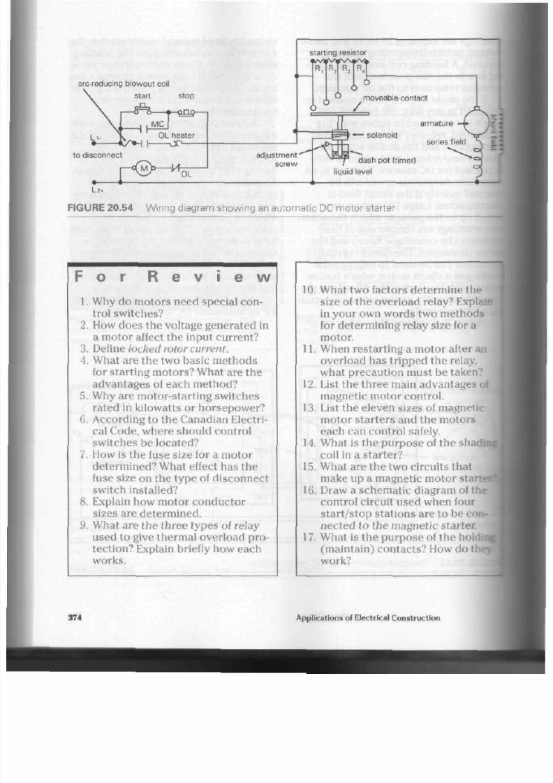
8/19/2019 Applications Electrical
http://slidepdf.com/reader/full/applications-electrical 379/447
arc-reducing blowo ut coil
start stop
starting resistor
R.
R R,
0
6
6
moveable contact
/
to disconnect
adjustment
screw
armature
— solenoid
series
field
dash pot (timer)
quid level
F I G U R E 2 0 . 5 4 W i r i n g d i a g r a m s h o w i n g a n a u t o m a t i c D C m o t o r s ta r te r
F o r R e v
i
e w
1. Why do motors need special con
trol switches?
2.
How does the voltage generated in
a motor affect the input current?
3. Define locked rotor current.
4.
W hat are the two basic m ethod s
for starting motors? What are the
advantages of each method?
5.
Why are motor-starting switches
rated in kilowatts or ho rsepow er?
6. According to the Canadian Electri
cal Code, where should control
switches be located?
7. How is the fuse size for a motor
determined? What effect has the
fuse size on the ty pe of d iscon nect
switch installed?
8. Explain how motor conductor
sizes are determ ined.
9. What are the three types of relay
used to give thermal overload pro
tection? Explain briefly how each
works.
10. What two factors determ ine the
size of the overload relay?
Explain
in your own words two method s
for determining relay size for a
motor.
11. When restarting a motor after an
overload has tripped the relay,
wh at p recau tion m ust be taken'.
1
12.
List the thre e m ain advan tages of
magnetic motor co ntrol.
13. List the eleven sizes of magnetic
motor starters and the motors
each can control safely.
14. What is the pu rpo se of the sh adi
coil in a sta rter ?
15. What are the two circuits that
make up a magnetic m otor stc
16. Draw a sche m atic diagram of |
control circuit used when four
start /sto p stations are to be
con-J
nec ted to the magnetic starter.
17. What is the purpose of the
holdi
(maintain) contacts? How do th<
work?
374
Applications of Electrical Construction
8/19/2019 Applications Electrical
http://slidepdf.com/reader/full/applications-electrical 380/447
18. List three types of control stations
that may be used with magnetic
motor star ters .
19. Why is more than one o verload
relay required in a 3 ph ase starter?
20 . How do es an overload relay used
with a magnetic motor sta rter
differ from a relay used on a man
ual starter.
21.
W hat is the pu rpo se of the jogging
circuit?
22. What is the danger when using a
push button jog circuit?
23 . Explain how a 3 ph ase m oto r is
reversed.
24.
What is the purpose of the inter
lock on a reversing controller?
25 .
W hat might hap pe n if a large
mo tor is reversed too quickly?
26. What is the difference betw een a
dual-speed motor controller and a
standard reversing controller?
27. What is the p urp ose of the timer
relay in a reduce d v oltage starter?
28.
Explain briefly how th e a uto tra ns
former starter operates.
29.
What are the advantages of using
the two types of reduced voltage
s tar ters?
30. Explain briefly how a single-phase
motor can be reversed.
31. What problem do both DC and AC
mo tors have when starting?
32. Define no-field
release.
33.
Why is no-field-release protection
important when using a DC motor?
34 . Define no-voltage-protection.
35.
W hy is an autom atic star ter safer
than a manual motor starter when
controlling
DC
motors?
36. What special features d oe s a solid-
state motor starter provide that
other types of starters do not?
Motor Control
375

8/19/2019 Applications Electrical
http://slidepdf.com/reader/full/applications-electrical 381/447
A
s in most building construction
areas, th e electrical trade relies
heavily on fastening devices to mount
boxes and panels, to support conduits
and cables, and to secure the many fit
tings associated with the trad e. Fasten
ing devic es are available in many forms
for the s up po rt of electrical equip me nt
on wood, steel, and all types of masonry
surface s. Due to th e variety of m aterials
that the fasteners must penetrate, they
are designed to accommodate either a
wood- or mac hine-type screw . To make
the best use of the fastening systems
available, an un derstand ing of wood
screw and m achine screw features is
desirable.
round
binding
Fastening I
Devices
Screw Fasteners
The following parts of a screw fastener
are im por tant to the installer and will b
discu ssed: head, driving configuration,
neck and/or shoulder, shank and body
thread, and point.
Head Des ign. The enlarged,
preforna
shape on one end of the screw is know
as the he ad. Heads are shaped to meet
the many requirements of the electria
and other industries. (See Fig. 21.1) Tk
oval and flat-undercut heads are
design ed to allow a semi-flush o r flust
with the surface of th e object being
(e.g., switch or receptacle cover plat
1
/2£k
f
-*^
u
>
rjZD £±
im
O
hex flange round flange flat undercut fillister
(hex washer) (round washer)
F I G U R E 2 1 . 1 C o m m o n h e a d d e s ig n s for s c rew f as t eners
376
Applications of Electrical Construction

8/19/2019 Applications Electrical
http://slidepdf.com/reader/full/applications-electrical 382/447
The other types of head are for use
where it is desirable to h ave the entire
head of the screw on the surface being
held (e.g., the cover on an octagon or
squ are box). The head of any threa ded
fastener is the bearing surface which
suppo rts the load.
Driving Configuration. To meet the
many installation problem s that are
enco untered , a variety of tools and /or
drivers are available for the screw
fasteners. Figure 21.2 illustrates th e
various driving configurations produced
in the heads of screws.
The slotted typ e is an old stan dard,
designed for the comm on screwdriver
found in most h om e or sh op a rea s. It is
produced in many sizes to meet the
requirem ents of the various screw sizes.
square
recess
hexagon
"Phillips"
Allen head
F I G U R E 2 1 . 2 C o m m o n h e a d c o n f ig u r a t io n s
f or s c rew f as t eners
The ele ctrician's tool kit would n ot
be com plete without a set of square
recess
(commonly known as Robertson
he ad) sc rew driv ers. This form of driving
configuration is patented under the
trade name of Scrulox. It is produ ced in
six sizes ranging from No. 4 (largest) to
No. 00 (smallest).
A colour-coded handle indicates th e
size of the dr iver as follows. No. 4 black
is for
No.
16 screw s and larger.
No.
3
black, which is som ewhat mo re com
mo n, is used for No. 12 and No. 14 gauge
screw s. No. 2 red drive rs install No. 8,
No.
9, and No. 10 gauge screw s. No. 1
green is for th e No. 5, No. 6, and No. 7
gauge s crew s. No. 0 yellow installs gauge
No. 3 and No. 4. The No. 00 o range-han
dled d river is for the tiny N o.
1
and No. 2
gauge screws.
The Scrulox design ha s two highly
desirable features. The squa re reces s for
the driver is tapered slightly and causes
the screw to "cling" once it has been
placed on the tip of the driver. This
allows the installer to use one hand on
the driver/screw combination and the
other hand to supp ort the equipment
being installed. Heat treating (harden
ing) along with proper recess design pro
duces an excellent driving configuration,
thus reducing the frequency of "cam-
out." Cam-out is the action between
driver and rec ess that cau ses the driver
to disengage from the recess in the head.
Scrulox units are ideal for use with
mechanical or power-operated
screwdrivers.
Phillips-type screws and drivers are
used extensively for appliance assembly.
This ty pe of driving configuration per
mits th e use of air- or electric-powered
driving tools, thus speed ing up assem
bly-line procedures. Screwdrivers are
available in sizes similar to th os e of th e
square recess driver, but are seldom
Fastening Devices
377
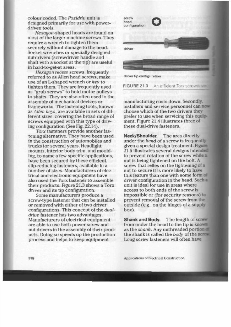
8/19/2019 Applications Electrical
http://slidepdf.com/reader/full/applications-electrical 383/447
colour coded. The Pozidriv unit is
designed primarily
for
use w ith power-
driven tools.
//exagon-shaped he ads a re found on
most
of
the larger machine screw s. They
require a wrench to tighten the m
securely without damage to the head.
Socket wrenches
or
specially de signed
nutdrivers (screwdriver handle and
shaft with
a
socket
at
th e tip) a re useful
in hard-to-get-at are as.
Hexagon recess screws, frequently
referred
to
as Allen head screw s, make
use of an L-shaped wre nch or key to
tighten them . They are frequently used
as "grub screw s"
to
hold motor pulleys
to shafts. They are also often u sed in the
assembly of mechanical devices or
frameworks. The fastening tools, known
as Allen keys, are available in sets of dif
ferent sizes, cove ring the br oad rang e of
screws equipped with this type of driv
ing configuration (See Fig. 22.14).
Torx
fasteners pro vide ano ther fas
tening alternative. They have bee n u sed
in th e construction of automobiles and
trucks for several yea rs. Headlight
m ounts, interior bod y trim, and mould
ing,
to
name
a
few specific applications,
have been sec ured by the se efficient,
slip-reducing fasteners, available in a
number
of
sizes. M anufacturers
of
elec
trical and electronic equipm ent have
also used the Torx fastener to assemble
their p rod ucts . Figure 21.3 shows a Torx
driver an d its tip configuration.
Some manufacturers prod uce a
screw-type fastener that can
be
installed
or removed w ith either of two driver
configurations. Th is concep t of th e dual-
drive
fastener has two advan tages.
Manufacturers of electrical equipm ent
are able
to
use both po wer screw and
nut drivers in the assembly of their prod
ucts . Doing so speed s up the production
process
and
helps
to
keep equipment
screw
head
c onf igur a t ion
driver
dr iver tip conf igurat ion
FIGURE 21.3 An efficient Torx screwdrnj
manufacturing costs down. Secondly,
installers and se rvice perso nnel can no
choose w hich
of
the two drivers they
prefer to use when servicing this equip
ment. Figure 21.4 illustrates thre e of
the se dual-drive fasteners.
Ne ck/Sh oulde r. The area directly
under the head of a screw is
frequently
given a special design treatme nt. Figim
21.5 illustrates several designs intende
to prevent rotation
of
the screw while
*
nut
is
being tightene d
on
the bolt.
A
screw t ha t relies on th e tightening of a
nut to secure
it
is mo re likely to have
this feature than one with some form a
driver configuration in the he ad. Such i
unit is ideal for u se in areas wh ere
access to both ends of the screw is
impo ssible or (for security reaso ns)
t<
prevent removal of the sc rew from the
outside (e.g., on the hinges of a supply
box).
Sha nk and Body. Th e length of sen
from u nde r the head
to
the t ip
is kne
as the
shank.
Any unth reade d portion
the shank is called the body of the
i
Long screw fasteners will often have
JIOWB
tioiU
scnJ
378
Applications
of
Electrical Construction

8/19/2019 Applications Electrical
http://slidepdf.com/reader/full/applications-electrical 384/447
p
a
combination hex and slot driver configuration
combination square recess and slot driver configuration
with square
recess drivers
with
Phillips drivers
corner clearance
for positive
sidewall engagement
acceptable for 2
driving or removing
5
wi th P hillips driver
o
no corner
engagement
positive engagement
even at slight angle
new Quadrex configuration using
square recess and Phillips drivers
FIGURE 21.4 Dual-drive fasteners
thre ad only at the tip are a, leaving a long
body. Shorter screws are frequently
threa ded over the entire length of the
shank, leaving no bo dy at all. When o nly
the necessary amount of thread is
formed on the shank, screw produ ction
time and costs are reduced and the
upp er portion of the screw is stronger.
rC7>
oval shoulder
fin neck
square (carriage) neck
F I G U R E 21 .5 C o m m o n n e c k a n d s h o u l d e r
d e s i g n s
8 F I G U R E 2 1 . 6 S m a l l d i a m e t e r ( G a u g e N o .)
a m a c h i n e s c r e w s
Thread Types. Many threa d types are
available, each designed to fasten
securely in a particu lar building
material. Some of the m ore co mm on
types are as follows.
Machine screws. These
bolt-and-nut
units w ere designed primarily to join
metal to a variety of othe r ma terials.
They are produced in many thicknesses
and thread pitches, depending on the
amount of support strength and/o r
compression between surfaces required.
The smaller diameter machine screws
(having a gauge num ber) are available
with a variety of head s hap es and
designs as seen in Figure 21.6. Larger
Fastening Devices
379

8/19/2019 Applications Electrical
http://slidepdf.com/reader/full/applications-electrical 385/447
I
carriage
bolts
hexagon
head cap
screws
machine
bolts
FIGURE 21.7 La rge d ia meter machine bolts
diameter units, frequently called
bolts.
are produ ced in three basic head shapes
as seen
in
Figure
21.7.
Most machine screw and /or bolt
sizes are produced with either coarse a
fine threa ds . The coarse-thread bolt
installs faster, since the nut advances
along the bolt
(thread pitch) a
greater
distance
for
each com plete turn . Fine-
threa d u nits require more turns of the
nut to tighten them, but excellent com
pression is obtained betw een the sur
faces joined. Table
21.1
compares com
mon coarse- and fine-thread screw sizes
with their m etric equivalen ts.
Instead a
producing metric screws that exactly
match their imperial measure (inches)
counterparts, manufacturers have
estal
lished
a
new set of popu lar m etric sizes
They have thu s avoided p roducing
TABLE
21.1 C omparing C ommon Coarse-and Fine-Thread Machine S crew S izes
Figures in this table are based on Unified scre w thread sizes as established by the A merican N ational Standards In stitute. The
tpi,
signify threads per
inch.
Unified Screw Threads
Coarse
no.
2
3
4
5
6
8
10
12
diam.
1/4
5/16
3/8
7/16
1/2
9/16
5/8
tp i
56
48
40
40
32
32
24
24
tp i
20
18
16
14
13
12
11
Fine
no.
2
3
4
5
6
8
10
12
diam.
1/4
5/16
3/8
7/16
1/2
9/16
5/8
tp i
64
56
48
44
40
36
32
28
tp i
28
24
24
20
20
18
18
Metric Screw Threads
Screw Thread
M2.2x0.45
M2.5x0.45
M3x0.5
M3.5x0.6
M4x0.7
M4.5x0.75
M5x0.8
M6x1
M7x1
M8x1.25
M 1 0 x 1 . 5
M 1 2 x 1 . 7 5
M 1 4 x 2
M 1 6 x 2
Example: To convert a 10-24 machine screw to metric, select M5
x
0.8.
Caution: Never mismatch m etric screws w ith imperial (inches) nuts or tapped
holes
380
Applications of Electrical C onstruction

8/19/2019 Applications Electrical
http://slidepdf.com/reader/full/applications-electrical 386/447
screw s in awkward dimension s
(decim als). The new screw sizes h ave
simplified metric dimensions that are
reasonab ly close to the inch units they
repla ce. Table 21.2 offers a co m paris on
between th e old and new fastener
dimensions.
For prope r installation, m achine
screws req uire a clearan ce hole to be
drilled or a pre-threaded hole in the
ma terials being joined. The internal
thre ads of the h ole or nut being used to
secure the assembly must match the
external threa ds of the b olt or mach ine
screw to prevent damage to either part.
Machine screw nu ts are shown in
Figure 21.8.
win g hex square
FIGURE 21.8 Machine screw nuts
TABLE 21.2 C omparison Guide for P opular Me tric and Imperial Fastener S crew S izes
Diameters
The range of diameters listed in metric standards is
from
M l
.6 to
M l 0 0 .
Wherever possible designers are
asked to use the stock and preferred sizes listed here.
Metric
Diameter
M2
M2.5
M 3
M3.5
M 4
M 5
M 6
M 8
M1 0
M12
M14
M16
M20
M2 4
M3 0
M3 6
M42
M48
M56
M64
M72
M80
M90
M100
Imperial Diameter
(Gauge/Inches)
#2
#3
#5
#6
#8
3/16
1/4
5/16
3/8
7/16
1/2
9/16
5/8
3/4
1
1 1/8
1 1/4
13/8
1 1/2
13/4
2
2 1/4
2 1/2
2 3/4
3
31/2
4
Lengths
The metric lengths given are the preferred lengths,
and these should be used wherever possible. Some
of the sho rter len gths wi ll not b e available in larger
diameters.
If lengths over 200 mm are required, then incre
me nts of 20 m m should be used, and for lengths over
300 mm, increments of 25 mm should be used.
Metric Length
(mm)
10
12
16
20
25
30
35
40
45
50
55
60
65
70
75
80
90
100
110
120
130
140
150
160
170
180
190
200
Imperial Length
(Inches approx.)
3/8
1/2
5/8
3/4
1
1 1/4
13/8
1 1/2
1 3/4
2
2 1/4
2 1/2
2 3/4
3
3 1/4
3 1/2
4
41/2
4 3/4
5
51/2
6
6 1/4
61/2
7
7 1/2
8
Fastening Devices
381

8/19/2019 Applications Electrical
http://slidepdf.com/reader/full/applications-electrical 387/447
Self-tapping screws. Self-tapping screws
are made of low-carbon, heat-treated
(hardened) steel and are available in five
basic types.
(1 )
Thread-forming
screws, as seen
in Figure
21.9,
reshap e the m aterial in
the pilot ho le and do not rem ove any of
the surrounding material. They provide
an excellent fit and fast assembly when
joining metal to metal.
(2 )
Thread<utting
screws are
designed w ith cutting edges and ch ip
cavities to remo ve material as they are
being installed. They are used in thick,
brittle, or granular materials w here
thread-forming screws are not suitable.
(See
Fig. 21.10)
(3) High-performance
thread-*
screws, shown in Figure
21.11,
en;
approximately
30%
more efficiently
ordinary self-tapping screws and 60%
more efficiently than machine screws
tapp ed hole s. Figure 21.12 illustrates
how the tight-fitting thread-forming
screw fits the material much more
securely than the tappe d hole and
mac hine screw with its thread
cle
Thread stripping and screw
breakage
virtually eliminated by the well-desipi
projections (spaced 120° apa rt at th e
tip) which form an accurate, mating
threa d in the screw-su pporting materi
These screws are ideal for
assembly-
production.
FIGURE 21.9 T hread-forming screws
8
CO
| FIGURE 21.11 High-performance tt
55 forming screws
FIGURE 21. 10 T hread-cutting screws
(4 )
High-performance thread<uttwg
1
screws are particularly suited for use
with brittle materials. Chips are quicttj
removed, reducing stripping or
cractti
hazards. These screws permit
quick,
easy assem bly and can be seen in
Figure
21.13.
(5 )
Metallic-drive
screws are
designed for perm anen t fastenings. T
are pressure driven by punch press or
ham me r into the holding material and
ar e well sui ted for attachi ng
nameplam
and covers, for example. Figure 21.14
illustrates this type of screw.
Wood
screws.
Wood screw s are used
it
man y different are as of the construct*
field and are available in four basic
thread configurations.
(1 ) Single lead (thread) tapered
wood screws have been in use for
mam
382
Applications of Electrical C onstruction

8/19/2019 Applications Electrical
http://slidepdf.com/reader/full/applications-electrical 388/447
S3
FIGURE 21. 12 Machine screw installation
(top) and thread-forming screw installation
(bottom)
~^ &
in
FIGURE 21. 13
cutting screws
High-performance thread-
ye ars . (See Fig. 21.15) The tapered neck
and shank design, however, caused fre
quent splitting problems w hen installed
in wood. The amou nt of torq ue required
to install the screw increases greatly as
it pe ne trate s de eper into the wood. As a
direct result of this increase in torque,
more stre ss is placed both on the screw
driver and on the installer.
a
w»
FIGURE
21.15
screw
A tapered thread woo d
(2) A more recent developm ent is
the
double lead
(thread) and fast-spiral-
thread screw. Produced under different
t rade names (Kwixin and Twin-fast), this
type of screw has a neck and body thick
ness that is less than th e thread diam e
ter. Splitting is virtually eliminated and
driver/installer stress reduced signifi
cantly due to this d esign. In addition, the
sides of the dou ble-threaded shank are
parallel, providing greater holding
power and faster penetration.
Figure 21.16 offers a comparison
between single- and double-lead wood
screws. The sharp point on the do uble
lead screw red uce s the need for pre-
5
single
thread
d o u b le
thread
FIGURE 21.14 A metallic-drive screw
FIGURE 21. 16
C omparison betw een single
and double thread screws
Fastening Devices
383
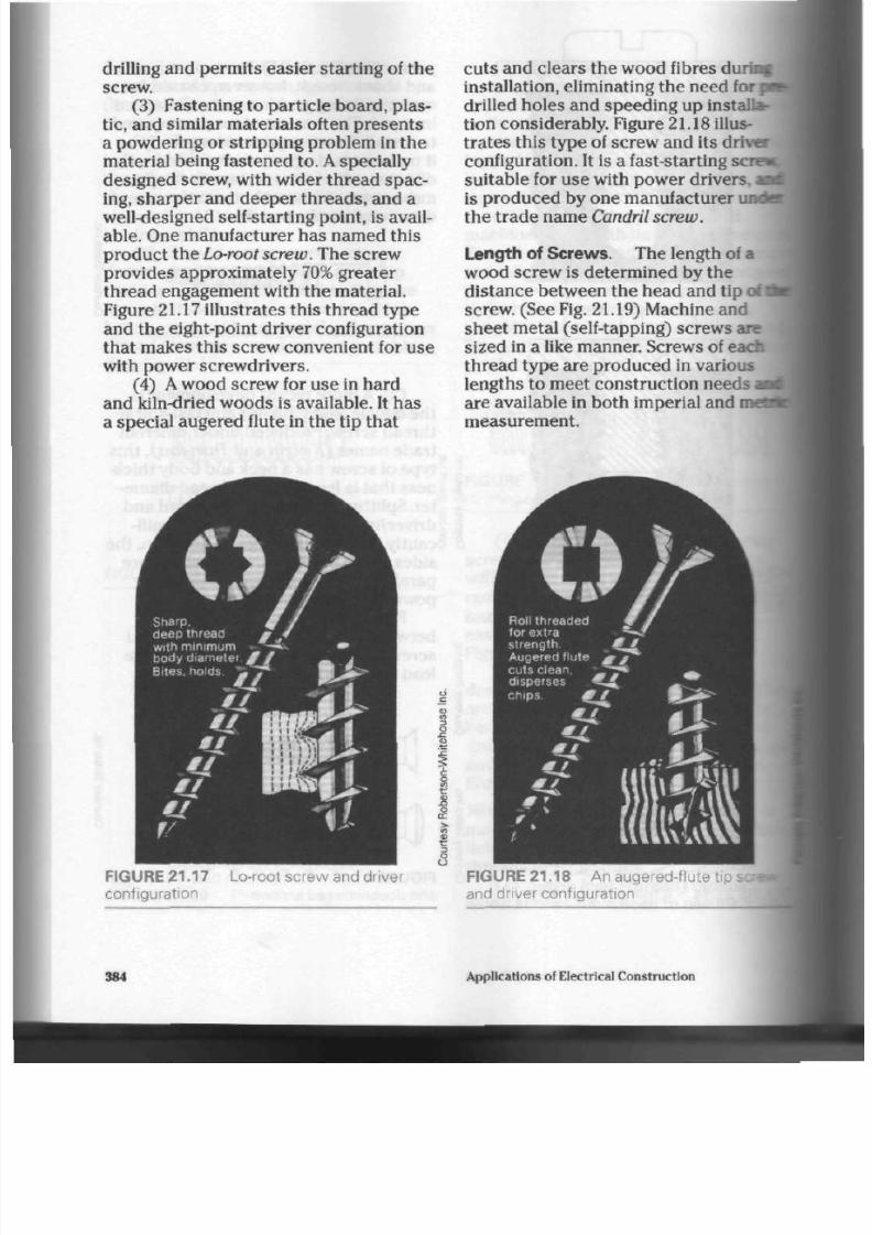
8/19/2019 Applications Electrical
http://slidepdf.com/reader/full/applications-electrical 389/447
drilling and permits easier starting of the
screw.
(3) Fastening to par ticle board, plas
tic, and similar materials often presents
a powd ering or stripping problem in th e
material being fastened to. A specially
designed screw, with wider thread spac
ing, sharper and deeper threads, and a
well-designed self-starting point, is avail
able. One manufacturer h as named this
product the
Lo-root
screw. The screw
provides approximately
70%
greater
thread engagement with the material.
Figure 21.17 illustrate s this thre ad typ e
and the eight-point driver configuration
that makes this screw convenient for u se
with power screwdrivers.
(4)
A
wood screw for use in hard
an d
kiln-dried
woods is available.
It
has
a special augered flute in the tip that
I for
cu ts and clears th e wood fibres di
installation, eliminating the need
drilled holes and speeding up installa
tion co nsid erab ly. Figure 21.18 illus
trates this type of screw and its driver
configuration. It is a fast-starting ser e*
suitable for use with power drivers. |
is produced by one manufacturer
<•
the trade name Candril screw.
sere-
Length of Sc rew s. Th e length of a
wood screw is determ ined by the
distan ce betw een the he ad and tip of i
screw . (See Fig. 21.19) M achine and
sheet metal (self-tapping) screws are
sized in a like manner. Screw s of each
thread type are produced in various
lengths to meet construction needs
are available in both imperial and
measurement.
2
FIGURE 21.17
configuration
Lo-root screw and driver
FIGURE 21.18 An augered-flute
t ip
and driver configuration
384 Applications of Electrical C onstruction

8/19/2019 Applications Electrical
http://slidepdf.com/reader/full/applications-electrical 390/447
length
length
length
FIGURE 21.19 Method of determining
screw length
Screw Diameter. Th e thickne ss, or
diameter, of a screw is indicated by a
gauge num ber ranging from 0 to 24. Th e
higher the gauge num ber, the thicker the
screw. Large, heavy-du ty screw -thread
units are available as illustrated in
Figure
21.20.
These lag bolts, as they are
called, find extensive use in
expansion-type masonry fasteners and
are available in standard machine bolt
diam eters and lengths.
Point Design. The tip or poin t of a
screw is designed to perform a variety
of
operations. Figure 21.21 illustrate s a
selection of point designs. Gimlet and
pinch points are for the penetration of
material.
Conical,
pilot (dog), and flat
(plain) points are to assist in the
alignment of the part s being sec ured .
Spherical, header,
and
chamfer
points
ease the insertion and starting of the
screw thread.
Screw Construction Materials.
Many
typ es of metal and alloy are used to
produ ce the many types of screws
available. Some of the more common
metals used are as follows.
Aluminum is used to prod uce a
s
I
FIGURE 21.20 Lag bolt
gimlet
conical
pinch
flat (plain)
header
spherical
FIGURE 21.21
screws
pilot (dog)
chamfer
Common point designs for
screw suitable for use with other alumi
num pro du cts where chem ical (gal
vanic) action between screw and mate
rial could take place. If other than
aluminum screw s were to be us ed,
severe damag e could result to the mate
rial.
Aluminum screw s ha ve less
strength than steel and brass screws,
and care must be taken during installa
tion not to twist them off.
Brass is used a great deal where cor
rosion from th e elem ents (rain, snow, air,
etc.) cou ld be a pro blem . It is easily
Fastening Devices

8/19/2019 Applications Electrical
http://slidepdf.com/reader/full/applications-electrical 391/447

8/19/2019 Applications Electrical
http://slidepdf.com/reader/full/applications-electrical 392/447
plated (chrome, etc.) by the manufac
turer for further corrosion resistance
and improved appearance. Silicone
bronz e is similar to b rass in strength and
corrosion resistance.
Monel, a nickel alloy, and stain less
steel are used where strength and extra
corrosion resistanc e are required. Steel
is by far the most com mon me tal used in
the manufacture of screws. It is stron g
and ea sily worked, and can be p lated for
resistance to corrosion.
Zinc or cadmium plating is applied
over the steel to pro tect it from corro
sion. Cadmium is the be tter of the tw o
coatings.
Bolt Strength. Steel hex-head m achine
bolts, or
ca p
screw s as they are often
called, are prod uce d in a num ber of
different tensile strengths, or SAE
(Society of Automotive Engineers)
grade s. The grade s rang e from 1 through
8 and the u ser is advised of the potential
holding power of each grade of bolt. A
simple pattern of ridges on the head
forms a grad e identification ma rk,
indicating the SAE rating. Table 21.3
illustrates typical markings, along with
size, load, strength, and hardness ratings.
Grade
1
and g rade 2 bolts can b e
used for the simple moun ting or fasten
ing of equipm ent w here strain and load
are not sev ere. The mid- and high-grade
units are used for heavy loads wh ere
stress and strain are greater, thus
preventing bolt or thread failure. As the
grade num ber increases, the carbon
steel of the bolt is subjected to a more
intensive heat/quench (hardening)
process .
Masonry Fasteners
Due to th e extensive use of m aso nry
m aterials (con crete, brick, etc.) in bo th
old and new buildings, a greater v ariety
of fastening devices ha s been develope d
for use by the construction trades. Much
of the electrical equipm ent installed
must be fastened to or sup po rted on
m ason ry surfaces, with one o r mo re of
the following fastening systems.
Screw A nchors.
Screw anc ho rs are
available in jute fibre, lead, n ylon, and
plastic. This comm on fastening dev ice is
inserted into a
pre-drilled
hole in the
ma sonry surface. A screw is then used
to com plete th e fastening system . Figure
21.22 illustrates lead and jute screw
anchors suitable for use with wood
scre w s. Figure
21.23
show s a well-
engineered plastic screw anchor which
can be used effectively with either a
wood or sheet metal screw. Whatever
anc hor is used should be as long as th e
threade d shank of the screw
(approximately of screw len gth).
Screw anc ho rs are also ma de in a variety
FIGURE 21.22 Screw anchors—lead (top)
and jute fibre (bottom)
FIGURE 21.23 A well-engineered plastic
scre w anchor for use in masonry materials
Fastening D evices
387
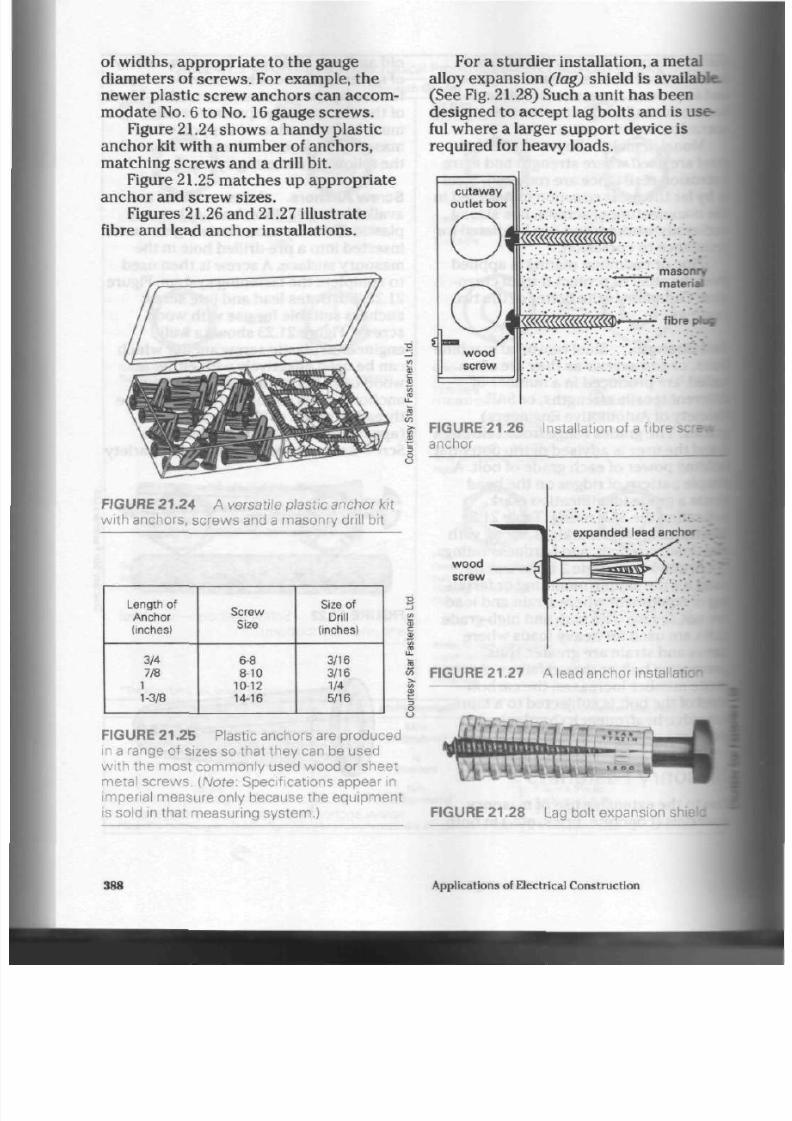
8/19/2019 Applications Electrical
http://slidepdf.com/reader/full/applications-electrical 393/447
of wid ths, app ropr iate to the gauge
diam eters of screws. For example, th e
newer plastic screw anchors can accom
modate
No.
6 t o
No. 16
gauge screws.
Figure 21.24 show s a handy plastic
anch or kit with a num ber of anc ho rs,
matching screws and a drill bit.
Figure 21.25 m atche s up app rop riate
anchor and screw sizes.
Figures
21.26
and 21.27 illustrate
fibre and lead anchor installations.
FIGU R E
21.24
A versat i le plast ic anch or k i t
wi th anchors, screws and a masonry dr i l l b i t
Length of
Anchor
(inches)
3/4
7/8
1
1-3/8
Screw
Size
6-8
8-10
10-12
14-16
Size of
Drill
(inches)
3/16
3/16
1/4
5/16
FIGURE
21.25
P lastic anch ors are pro duc ed
in a range of s izes so that they can be used
w i t h t h e m o s t c o m m o n l y u s e d w o o d o r s h e e t
m e t a l s c r e w s . (Note: S peci f icat ions appear in
imper ia l meas ure on ly bec aus e t he equipment
is sold in that measuring system.)
For a stur die r installation, a metal
alloy ex pansion (lag) sh ield is available.
(See Fig. 21.28) Such a un it h as been
designed t o acce pt lag bolts and is use
ful where a larger su pp or t d evice is
required for heavy loads.
cutaway
outlet box
i«£«» ;;
:
:
;
i;":'
masonry
material
«•'
••"';
fibre plus
FIGU R E 21 .26 Insta l lat ion of a f ibre
anchor
wood
screw
1
..-':
expanded lead anchor
81
<7> F IGURE
21.27
A lead anch or instal lat ion"
^ jrmji ;? -.
FIGURE
21.28
Lag bol t expa nsion sh
388
Applications of Electrical Construction

8/19/2019 Applications Electrical
http://slidepdf.com/reader/full/applications-electrical 394/447
Expansion Shields.
Expansion shields
are primarily designed for use with
ma chine o r lag bo lts. The se zinc alloy
units are produc ed in various lengths
and diam eters, with internal threa ds in
common machine screw/bolt sizes. A
hole of the correct diameter, as
indicated on the expansion shield, m ust
be drilled into th e m aso nr y for th e full
depth of the shield. The shield is then
inserted and the m achine or lag bolt
threade d into position. As the bolt is
tightened, the threaded section of the
shield is drawn tow ards the mo unting
surface, expanding th e bod y of th e
shield against the sides of the
pre-drilled
hole. Since the shield can exert great
pres sure on the sides of the hole as it
expa nds, care m ust be taken to use it in
solid or firm m aso nry m aterial. If not,
cracking of the m ason ry and releas e of
the shield can result. Figure 21.29
illustrates two types of the se s hields.
2
to
FIGU RE 21.29 Z inc al loy expa nsion shields
Self-Drilling Shield. A hardened steel
expansion shield has been produced. It
is capa ble of drilling its own hole . (See
Fig.
21.30)
The bo dy of the shield h as a
break-off,
tapered end which is held in a
power hammering device during
installation. Once the harden ed teeth at
the tip of the shield have drilled the
hole, a tapered steel plug is inserted into
F I G U R E 21.30 A harde ned stee l , sel f-
dr i l l ing, expansion shield and plug
th e
t ip.
The shield assem bly is then
placed back in the m ason ry ho le. Fur
ther pressure from the power hammer
drives the tapered
steel
plug up into the
shield, expanding the cutting tips and
widening the bottom of the hole. This
typ e of shield ha s extraordina ry holding
power du e to the increased hole and
shield diameter at the base of the hole.
Th e taper ed knock-off neck of the sh ield
can be rem oved easily onc e the shield
has been fully installed. A bolt of higher
SAE grade can be used with these
shields, since the internal thre ads of the
shield are also formed of hardened steel
Figures
21.31
and 21.32 illustrate th e u se
of expansion and self-drilling shields.
Lead Sle eve Anchor. A
simplified form
of expan sion sh ield is illustrated in
Figure
21.33.
These u nits are placed in a
pre-drilled h ole and set in to their final
machine
bolt
steel
bracket
FIGURE 21.31
installation
Shield expands against sides
of hole.
v - - .
J
. : - . : -
ole in
•
masonry
A z inc al loy expansion shield
Fastening Devices 38

8/19/2019 Applications Electrical
http://slidepdf.com/reader/full/applications-electrical 395/447
removable tapered neck ,_ . ....
••';.;.'•.-vA.••'.", '•.•.'.'. tapered steel plug
.'-"..'.
J
' '' cutting teeth ..-.
•
•" '• • .•
' internal threads ' • " ••^
,
~I
£c£
:
;-.
,'.".;-. body :_;.:•. .'•;.•; ;..••• •>• ' . .• . :• . '
-'.'•'.'.. Hole and shield widens at base.
F I G U R E 2 1 . 3 2 A h a r d e n e d s t e e l, self-
dri l l ing, expansion shield instal lat ion
expanded position by a setting tool. (See
Fig.
21.34) Blows from a hammer provide
the necessary force to expand the lead
anchor into irregularities in the sides of
the hole. Figure 21.35 illustrates this
process.
An
internally threaded,
zinc-alloy cone assists in the expansion
and accepts standard machine
screws/bolts in
a
variety of
sizes.
Sleeve
anchors do not provide as m uch holding
power as o ther types of fasteners, but
are widely accepted for use in position
ing
machinery on a concrete floor. The
unit illustrated in Figure 21.35 uses a
machine bolt instead of a
FIGURE 21.33
FIGURE 21.34
Lead sleeve anchors
•^TipTiMPIM -
Lead sleeve setting tool
threaded cone. The bolt is left protrud
ing from the floor; the m achine is then
put into position and a standard
FIGU RE 21.35 Instal lat ion of a lead s leeve anchor and bol t
390 A pplications of E lectrical C onstruction

8/19/2019 Applications Electrical
http://slidepdf.com/reader/full/applications-electrical 396/447
nut placed on the threaded end of the
bolt to tighten it in place.
Drive-in Anchors. Drive-in an ch ors are
basic expansion shields that a re secured
in masonry material by driven nails or
pins.
A
hole must b e
pre-drilled
in th e
mounting surface; an anchor is then
placed through the device being
supported and inserted into the
masonry hole.
A
series of blows from a
hammer will drive th e nail or pin into t he
shield, thus expanding the back po rtion
of th e shield against th e sides of the
hole. The shield itself supports the load
with this type of fastener, sinc e it pa sse s
through the device being supported.
One example of this type of unit is
illustrated in Figure 21.36. These u nits
are normally produced in sm aller
diam eters (5 mm to 13 mm for light-duty ]
applications. j
FIGURE 21.36 Drive-in anchor
i
Drilling Devices
Hammer-Driven Units.
In th e past,
holes in masonry surfaces w ere made
with the use of a hand-held,
hammer-driven, masonry drill. This
manual drill is still used by installers,
especially in areas w here electric or air
pow er is not readily available. It com es
in two parts as shown in Figures 21.37A
and B. The drill holder ha s a rubb er grip
assem bly to lessen the hamm ering
vibrations during drilling and to protect
the user's hand. The drill bits are formed
of high-quality carbon steel. They are
hardened, temp ered, and sharpen ed at
the tip to produce a relatively quick hole
in concrete, brick, or stone surfaces. The
shan k is tap ere d at the end to fit easily
into the drill holder. It is rec om m ende d
that the drill unit be rotated by the oper
ator during the drilling process to pre
vent binding and even tual breakage of
th e drill bit in the ho le. Drill bits ar e pro
duce d in sizes up to 15 mm diam eter for
use with th e smaller expansion type
shields.
Larger holes can be produced with a
four-point d rill, available in diam eters up
to 40 m m. Four-point drills are also
m ade in leng ths of 380 mm and 460 mm
whe re a dee p hole must be made, or
access to the work surface is awkward.
Figure 21.38 illustrat es this ty pe of dril
ling device. This hard ened -steel drill is
for use on all m aso nry su rfaces and
should be rotated d uring use to prevent
binding and/or jamming in the hole.
Power-Driven Units. Due to th e
pop ularity and availability of good
quality electric drills, a m aso nry drill bit
FIGURE 21.37A A manual, rubber grip,
masonry drill holder
FIGURE 21 37B Drill bit for a ma sonry drill
holder
FIGURE 21.38 A four-point masonry dril
Fastening Devices 391

8/19/2019 Applications Electrical
http://slidepdf.com/reader/full/applications-electrical 397/447
has been produced for use with these
tools.
Air-powered drills can also u se
this type of bit for work on masonry sur
faces.
Th e shap e of the bit closely
resem bles that of a stand ard steel drill
bit. Th e cutting tip, however, is mad e
from a small piece of carbide brazed
(welded) into position. The carbide is an
extremely hard metal, capa ble of cutting
clean, fast, and a ccu rate ho les in most
masonry surfaces. The hardness of the
carbide tip makes it necessary to
re -
sharp en s uch a bit on a grinding wheel
specially compounded for the purpose.
Attempts to sharpen the bits on a stand
ard grinding wheel usually result in the
wearing dow n o r forming of grooves in
the grinding wheel itself. The bits are
prod uced in a variety of sizes, and sam
ples of the se are sh ow n in Figure 21.39.
The carbide bit is excellent for use with
most of the smaller fastening devices.
Figure 21.40 illustrate s t he us e of car
bide bits.
Larger holes can be prod uced in
m ason ry surfaces w ith a "multi" car
bide-tipped, spiral flute drill. This unit
ha s a hollow co re, allowing clearanc e i
chi ps and remo val of larger piec es of tf
m ason ry m aterial. Figure
21.41
illus
tr at es this form of drill bit. Drill bits
ate
available in assorte d d iam eters and
lengths to meet the needs of most large-
hole installations. Due to th e cos t
of
the se drill units, care should be taken
during the drilling not to damage or
remove the carbide cutting tips.
Removal of the drill bit from the hole
several times during the drilling
opera
tion will aid in chip cle aran ce and pro
long the life spa n of the bit.
Hollow-Wall
Fasteners
Many fastening op eration s are per
formed in residential or other buildings
where plaster materials are applied
to the wall and ceiling areas. These
surfaces are generally too thin and low
in density to accom mo date other thaa
the small screw-type anchors. There B
depth
of hole
to match
fastener
masonry
wall ,
M
carbide tip:.- '••.'. '•; .'•'.
F I G U R E 2 1 . 4 0
3
surfaces
Dri l l ing a hole in
masor
2
2
F I G U R E 21.39 C arb ide- t ipped, pow e r-
dr iven masonry dr i l l b i ts
F IG U RE 2 1 .4 1 A " m u l t i " carbide-tippt
masonry dr i l l
bit
392
Applications of Electrical Construction
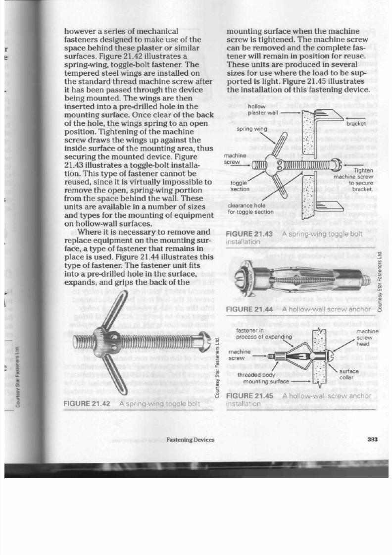
8/19/2019 Applications Electrical
http://slidepdf.com/reader/full/applications-electrical 398/447
however
a
series
of
mechan ical
fasteners designed
to
make use
of
the
space behind these
plaster or
similar
surfaces. Figure 21.42 illustrates
a
spring-wing, toggle-bolt fastener. The
tem pered steel wings are installed
on
the standard thread machine screw after
it has been passed through
the
device
being m oun ted. The wings are then
inserted into
a
pre-drilled hole in the
mo unting surface. Once clear
of
the back
of th e hole, the wings spring
to
an open
position. Tightening
of
the machine
screw draw s the wings
up
against
the
inside surface
of
the m ounting area, thus
securing the m ounted device. Figure
21.43 illus trates a toggle-bolt installa
tion. This typ e of fastener ca nnot be
reused, since
it
is virtually im possible
to
remove th e open, spring-wing portion
from th e sp ace beh ind th e wall. Th ese
units are available
in a
number
of
sizes
and types
for
the m ounting
of
equipment
on hollow-wall surfa ces.
Where
it is
necessa ry to remove and
replace equipm ent on the mounting sur
face, a type of fastener that rem ains in
place is us ed. Figure 21.44 illustrates this
type
of
fastener. The fastener unit fits
into
a
pre-drilled hole
in
the surface,
expands, and grips the back
of
the
mounting surface when the machine
screw is tightened. The machine screw
can be removed and the complete fas
ten er will remain
in
position
for
reuse.
These units are produced
in
several
sizes
for
use where th e load
to
be sup
ported
is
light. Figure
21.45
illustrates
the installation
of
this fastening device.
hollow
plaster
wall
spring wing
Tighten
machine screw
to secure
bracket
clearance hole
for toggle section
FIGURE 21.43
A
s pr ing- w ing t ogg le b o l t
instal lat ion
F I G U R E 2 1 . 4 4
A
ho l low - w al l s c rew anc hor
fastener
in
process of expanding
machine
screw
/
threaded body
mounting surface
machi
screw
head
FIGURE 21.42 A spring-wing toggle bolt
FIGURE 21.45
installation
A hollow-wall screw anchor
Fastening Devices
3

8/19/2019 Applications Electrical
http://slidepdf.com/reader/full/applications-electrical 399/447
Powder-Actuated Fasteners
The drilling
of
holes
in
masonry
or
steel
surfaces is
a
tedio us and often time-con
suming operation. L abour versus fas
tener costs must be considered when
choosing
a
fastening system. Powder-
actuated fastening s ystem s speed u p fas
tening time and greatly redu ce the physi
cal strain on the installer. These systems
release much energy at the time
of
firing,
making it necess ary
to
fully tra in com pe
tent o per ato rs. Manufacturers of
powder-actuated tools and acce ssories
are m ost willing to train and advise
installers
in
the use
of
their e quipm ent.
In accorda nce w ith th e
CSA
standard for
powder-actuated tools (CSA, CAN 3-
Z166-M85), man ufacture rs
of
thes e tools
must train tool u ser s. After training,
the
potential tool user is tes ted through a
written examination and actual use of
appro priate fasteners in the tool. When
she
or
he has successfully com pleted
the test, an ope rato r's licence is issued.
(See Fig. 21.46) Powder-actuated tools
are divided into two main categories:
low- and high-velocity s yst em s.
Low-Velocity E quipment.
Low-
velocity tools ope rate at 90 m/s or less
and are suitable
for
fastening to most
masonry
or
steel surfaces. They are the
safest form of pow der-actuated tool
available, partly bec au se both piston
and fastener m ust be accelerated by the
powder charge. If
at
any time t he
fastener should pass through the
receiving surface, its speed and energy
will not
be
sufficient
to
endanger human
life. These tools have
a
somew hat higher
recoil than the high-velocity tools but
are quieter in operation. Due to the low
velocity
of
th e fastener, the tool do es n ot
have
a
controlled fire angle. This feature
is most necessary, however, on the
NOT TRANSFERABLE
®
Ramset
FASTENING SYSTEMS
QUALIFIED OPERATOR OF
EXPLOSIVE ACTUATED TOOLS
This Cer t i f ies that
has received training
in the
operation
of
the Ramset explosive actuated tool speci
fied herein,
has
passed
the
examination,
and
is
deemed com petent to operate such
a
tool.
Daiecf Issue
NO.
Manufacturer's Certified Agent
IN
ACCORDANCE WITH
CSA STANDARD Z166
FIGURE
21.46
A licence for operating
explosive-actuated tools
high-velocity to ols. A levelling device is
available as an option with the low-
velocity too ls an d will provide fire angle
control
if
desired.
The low-velocity tools are designed
and manufactured
in
accordance with
the CSA standard and must incorporate
several safety features: air-fire safety
to
prevent the tool from being discharged
into the air like a regular gun, a
safety
trigger lock to prevent accidental firing
when the tool is not
in
use , and drop-fire
prevention
to
prevent accidental firing if
th e tool is dro pp ed on the floor.
A
well-
designed buffer system prevents over-
travel
of
the d rive mechanism
if
and
when improper charges are inserted.
Figures
21.47
and
21.48
illustrate th e
mechanisms of low-velocity t oo ls.
Operation. Th e low-velocity tool
discharges a powder cartridge inside the
394
App l i ca t i ons of El ec tr i ca l C ons t ruc t i on
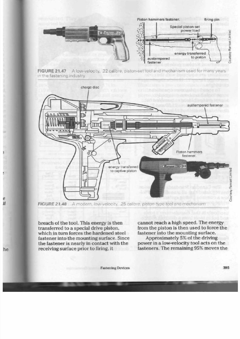
8/19/2019 Applications Electrical
http://slidepdf.com/reader/full/applications-electrical 400/447
Piston hammers fastener.
f i r ing p in
Special piston-set
power load
•;i austempered
fastener
FIGURE 21.47 A low-ve locity, .22 calibre, piston-set tool and mec hanism used for many years
m the fastening industry
charge disc
austempered fastener
FIGURE 21.48 A m odern, low-velocity, .25 calibre, piston-type tool and mechanism
breach of the tool. This energy is the n
transferred to a special drive piston,
which in turn forces the harde ned steel
fastener into the mounting surface. Since
the fastener is nearly in contact with the
receiving surface prior to firing, it
canno t reach a high spee d. The energy
from the piston is then used to force the
fastener into the m ounting surface.
Approximately
5%
of th e driving
pow er in a low-velocity tool a cts on th e
fasteners. The remaining
95%
moves the
Fastening Devices
395

8/19/2019 Applications Electrical
http://slidepdf.com/reader/full/applications-electrical 401/447
piston, which is designed in such a way
that it cann ot leave the tool.
Powder-Charge Cartridges.
The
explosive u sed in low-velocity tools
com es in the form of a brass and/o r
nickel rim fire cartrid ge. T hese
cartridg es are factory-loaded to prec ise
power levels and are given both a
number and a colour code to indicate
the se levels. Both cartridge and bo x or
container are equipped with the code
markings. Figure 21.49 show s som e
cartridges.
To speed up fastener op eration s,
some tools have been designed to
accep t groups of loads assembled onto
strips or discs. Figures 21.50 and 21.51
illustrate this method of load handling.
FIGURE 21.50
loading system
A multiple cartridge disc
M M * * * "
a
«*- *
V ,
FIGURE 21.51
ing cartridges
A lternative method of
FIGURE 21.43 A .22 calibre, rim fire, low-
velocity cartridge (left); .22 calibre, rim fire,
high-velocity c artridges (centre); a .38 calibre,
centre fire, high-velocity cartridge (right)
The Canadian Standards Association
has regulated that all manufacturers fol
low a common coding system for car
tridge pow er levels. Cartridges supplied
by a manufacturer should, however, be
used only in tha t manufacturer's tools
and not in tools from a different source.
The cartridg e coding system is outlined
in Table 21.4.
Fasteners. Four basic typ es of
fasteners are available. Drive pins are
used to nail materials directly to
TA BLE 21.4 P ower Loads (In Accoraa
with the CSA
Z166
Standard)
Low-
Velocity
Tools
High-
Velocity
Tools
Load
No.
1
2
3
4
5
6
7
8
9
10
11
:2
Case
Brass
Brass
Brass
Brass
Brass
Brass
Nickel
Nickel
Nickel
Nickel
Nickel
Nickel
L c s :
Cotow
B--
S M
v
e " I
~-z
P. . -
£ . . .
G - ~ -
v^ -
-~-
"-•; =
concrete, steel, and
horizontal
mortar
joints. They are perm anent fasteners,
intended for use with equipmen t that
doe s not need to be removed and
396
Applications of Electrical Construction

8/19/2019 Applications Electrical
http://slidepdf.com/reader/full/applications-electrical 402/447
rem ounted . They are available in
asso rted lengths and d iame ters to fit the
tool system.
Threaded studs
are for use where
washer-and-threaded-nut mounting is
desire d, e.g., to facilitate removal and
remoun ting of equipm ent. They are also
ideal wh ere adjustment or repositioning
of the equipment is sometimes neces
sary. Care should be taken not to
over
tighten the nut; otherw ise, the stud will
be loosened in the mou nting surface
material. These versatile fasteners are
produced in
4
in. (6 m m) and
%
in.
(10 mm) threa d d iame ters, with various
thread and shank lengths to suit many
applications.
Eye pins find considerable use in
suspended ceiling installations, hanging
lighting fixtures, and attaching veneers
or wire mesh to co ncre te. They are
available in several sizes and lengths
for use in both high- and low-velocity
tools.
Light fixtures an d su spe nd ed ceil
ings often require the extra holding
strength achieved with the high-velocity
tool.
A
specially designed
clip-and-fasten
is available for use with the low-velocity
tool when fastening conduit or other fix
tures.
Fastening Surfaces. Figure 21.52
illustrates a few combinations of mat
erials that can be secured or sup
ported by powder-actuated fasteners.
W hen a stud or pin is fired in to con
crete (or similar, non-brittle masonry), a
compressive bond or ball is formed
around the point of the fastener. This
studs into steel
3 E
wood or non-metals
to steel
steel to
steel
•f'.'.'.'si
o • •
•
o:
O .
• • • 0 V
r> -
studs into concrete
wood or non-metals
to concrete
steel to concrete
conduit clips
under floor
electrical duct
= &
J
signs
panel boards
and junction
boxes
light
fixtures
timber framework
FIGURE 21.52 C ombinations of material to be secured by powder-actuated fasteners
suspended
ceilings
Fastening Devices
397

8/19/2019 Applications Electrical
http://slidepdf.com/reader/full/applications-electrical 403/447
area acco unts for much of the holding
power, and so the fastener sho uld be
driven into the co ncre te to a dep th of
approximately
3
A
in. (20 mm ) when
securing to high strength con crete or at
least l'/4 in. (32 mm ) when fastening into
low strength con crete . Maximum hold
ing power is achieved when the strength
of the c onc rete in area
X
of F igure
21.53A
is greater than the bond at the point. If
penetration is not sufficient, the fastener
may pull out under load, removing a
cone-shaped section of the con crete as
indicated by the d otted lines in the
figure.
Con crete requires abo ut twenty-eight
days to reach its full compressive
strength. Any fastener set in "green"
concrete (less than four days old) will
only deve lop low holding power, but will
improve slightly as the concrete ages. It
is not recommended that fasteners be
driven into any concre te that is
less
than
four days old.
The small chips of con crete (known
as
spa/0
that break away from around
the pin area do not lessen th e holding
pow er of the fastener.
A
spall guard o n
the fastening tool will help eliminate
this, however, and improve the appear
an ce of the finished job . (See Fig.
21.53B)
Any fastener driven into a hollow
block must not be allowed to protru de
through the block. The compressive
bond at the point is lost com pletely
und er the se cond itions and little or no
holding pow er will be th e result.
Fasteners sh ould no t be driven into ver
tical mo rtar se am s on any brick or block
wall. M ortar in these seam s tend s to be
less in quantity and definitely lacking in
com pressive s trength. Only horizontal
mortar seams provide sufficient quantity
of material and adequate compressive
strength for holding power.
Care shou ld b e taken to drive sev eral
spall area
— stud
pull-out cone area
t
.' •'• • ;•': •'•''; v? ," *> compressive baJ
" ; i ;
;
. •. section of concrete ':
.].
'.•; A
FIGURE 21 53A A threaded stud in
concrete
FIGURE
21.53B
T hreaded studs driven in
concrete without a spall guard (left) and .
spall guard (right)
test
pins into an out-of-the-way area
of
the mounting surface to determine
proper cartridge strength and fastener
size.
Use great care to ensure th at the
fastener does not pass completely
through the receiving surface and
endanger som eone on the other side.
Always start with the weakest charge
and progress u p in strength until the
CM
rect combination is determined.
The use r of a pow der-actuated tool
sho uld be familiar with th e minimum da
tance recommended between fasteners.
398
Applications of Electrical Construction
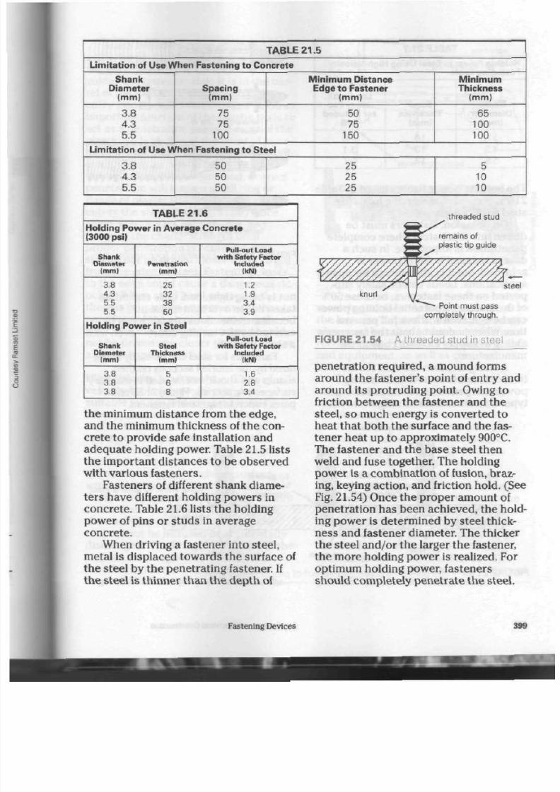
8/19/2019 Applications Electrical
http://slidepdf.com/reader/full/applications-electrical 404/447
T A B L E 2 1 . 5
L imi tat ion of Use When Fastening to Concrete
Shank
Diameter
(mm)
3.8
4.3
5.5
Spac ing
(mm)
75
75
100
Min imum D is t anc e
Edge to Fastener
(mm)
50
7 5
150
M i n i m u m
Thickness
(mm)
65
100
100
L imi tat io n of Use Wh en Fastening to S teel
3.8
4.3
5.5
50
50
50
2 5
2 5
25
5
10
10
T A B L E 2 1 . 6
Holding Power in Average Concrete
(3000 psi)
S hank
Diamet er
(mm)
3.8
4.3
5.5
5.5
P enet rat ion
(mm)
25
32
38
50
P ul l - out Load
w i t h
Safety
Factor
Inc luded
(kN)
1.2
1.9
3.4
3.9
Holding Power in Steel
S hank
Diameter
(mm)
3.8
3.8
3.8
Steel
Thickness
(mm)
5
6
8
P ul l - out
Load
w i t h Safety Factor
Included
(kN)
1.6
2.8
3.4
the minimum distance from the edge,
and the minimum thickn ess of the con
crete to provide safe installation and
adequate holding power. Table 21.5 lists
the important distances to be observed
with various fasteners.
Fasteners of different shank diame
ter s have different holding pow ers in
con crete . Table 21.6 lists the holding
power of pins or stu ds in averag e
concrete.
When driving a fastener into steel,
metal is displaced towards the surface of
the steel by the p enetrating fastener.
If
the steel is thin ner tha n the d epth of
threaded stud
steel
Point must pass
completely through.
FIGURE 21.54 A threaded stud in steel
penetration required, a mound forms
around the fastener's point of entry and
around its protruding point. Owing to
friction between the fastener and the
steel, so much energy is conv erted to
heat that both the surface and the fas
tener heat up to approximately 900°C.
The fastener and th e base steel then
weld and fuse together. The holding
pow er is a comb ination of fusion, braz
ing, keying action, a nd friction hold. (See
Fig. 21.54) On ce th e pro per am ount of
penetration has been achieved, the hold
ing pow er is determ ined by steel thick
ness and fastener diameter. The thicker
the steel and/or the larger the fastener,
the m ore holding pow er is realized. For
optimum holding power, fasteners
should completely penetrate the steel.
Fastening Devices

8/19/2019 Applications Electrical
http://slidepdf.com/reader/full/applications-electrical 405/447
TABLE
21.7
Holding P ower in Steel Using High-V elocity
Fastening Tools
Shank
Diameter
(mm)
3.8
4 .3
5.5
Steel
Thickness
(mm)
10
10
12
Pull -out
Load w ith
Safety Fac
tor Included
(kN)
2.8
3.1
6.7
The ho lding pow er figures listed in Table
21.7 represe nt safe working loads for
steel applications.
On occasion , fasteners must b e
driven into thick steel where com plete
pen etration is impo ssible. In such a
case, a redu ced holding pow er is
achiev ed, but it is still enough for m ost
application s. Loads can be safely s up
ported on these fasteners, because 50%
of the fastener's potential holding power
can be achieved without full penetra
tion. When in dou bt abo ut the fastener's
ability to sup po rt a load, consult th e
manufacturer.
A
straight
spline-knurl
on the fas
tener's shank increases the holding
power and preve nts the threaded-stud
typ e of fastener from tu rning w hile the
i n
fasteners for use in
masonry materials
fasteners for use in steel
FIGU R E
21.55
Fas t eners f or ma s onry
steel
nut is being tightene d. Care should be
taken not to overtighten the nu t,
because tremendous pressure can be
exerted b y the turning
effort—even w *
a short w rench.
Fasteners for steel can b e easily
recof-
nized by the knurled sections on their
shanks and should not be used in
mason
surfaces or materials. Figure
21.55
com
pares concrete and steel fasteners.
threaded stud
Most of tip
guide is visible
'on surface.
Tip guide
is
badly
'shredded.
Upper end of tip guide is
i
. /
. steel beam
too little
FIGU R E 21 .56 T he plast ic t ip guide gives proo f of proper pen etra t ion.
400 Applications of Electrical Construction
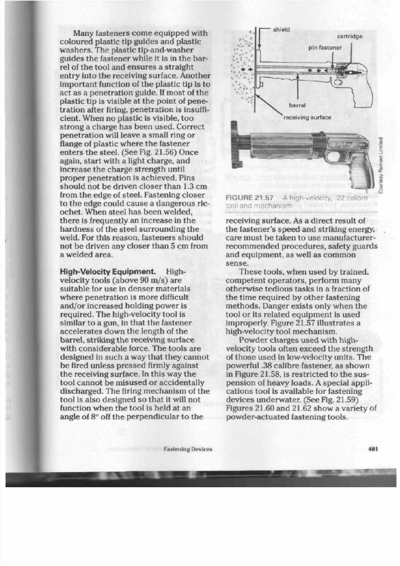
8/19/2019 Applications Electrical
http://slidepdf.com/reader/full/applications-electrical 406/447
Many fasteners com e equipped with
coloured plastic tip guides and plastic
washers. The plastic
tip-and-washer
guides t he fastene r while it is in th e bar
rel of the tool and ensures a straight
entry into the receiving surface. Another
im por tant function of the plastic tip is to
act as a pe net ratio n gu ide. If mo st of the
plastic tip is visible at th e po int of pene
tration after firing, penetration is insuffi
cient. W hen no plastic is visible, too
strong a charge has been used . Correct
pe netra tion will leave a small ring or
flange of plastic whe re the fastener
en ters th e ste el. (See Fig. 21.56) Once
again, sta rt w ith a light charg e, and
increase the ch arge strength until
proper penetration is achieved. Pins
should not be driven closer than 1.3 cm
from th e edge of steel. Fastening clo ser
to the edge could caus e a dangero us ric
oche t. When steel has been w elded,
the re is frequently an increase in the
hardness of the steel surrounding the
weld. For this reason, fasteners should
not be driven any closer than 5 cm from
a welded area.
High-Velocity Equipment.
High-
velocity tools (ab ove 90 m/s) a re
suitable for use in denser materials
wh ere pene tration is m ore difficult
and /or increased holding power is
requ ired. Th e high-velocity tool is
similar to a gun, in that th e fastener
accelerates down th e length of the
barrel, striking the receiving surface
with considerab le force. The tools are
designed in such a way that they canno t
be fired unless pressed firmly against
th e receiving surface. In this way th e
tool canno t be misused or accidentally
discharged. The firing mechanism of the
tool is also designed so tha t it will not
function whe n the too l is held at an
angle of
8°
off the perpendicular to the
<sv
shield
cartridge
pin fastener
barrel
"receiving surface
FIGURE 21.57 A high-velocity, .22 calibre
tool and mechanism
receiving surface . As a d irect result of
the fastener's speed and striking energy,
care must be taken to use manufacturer-
recommended procedures, safety guards
and equipm ent, as well as com mon
sense.
The se tools, when used by trained,
com petent operators, perform many
oth erw ise ted iou s task s in a fraction of
the time required by oth er fastening
m etho ds. Danger exists only when th e
tool or its related equipment is used
improperly. Figure 21.57 illustrates a
high-velocity tool mechanism.
Powder charges used with high-
velocity tools often exceed the strength
of tho se used in low-velocity un its. The
powerful .38 calibre fastener, as sho wn
in Figure 21.58, is restricted to the su s
pension of heavy loads. A special appli
catio ns tool is available for fastening
dev ices und erw ater. (See Fig. 21.59)
Figures 21.60 and 21.62 show a variety
of
powder-actuated fastening tools.
Fastening Devices
401

8/19/2019 Applications Electrical
http://slidepdf.com/reader/full/applications-electrical 407/447
FIGURE 21.58
tool
A .38 calibre high-velocity
Safety Equipment. As pe r CSA
standards, personal protective
equipm ent should be worn by the tool
opera tor and any helpers or ob servers
in hazardo us proximity to the operation
FIGURE 21.59
underwater use
A high-velocity too l for
of the too l.
It
should include protective
headgear (hard hat) along with safety
gla sses or goggles. (See Fig. 21.61) Noise
levels from the more powerful tools
(especially in confined are as) make ear
pro tection well wo rth co nsidering. Com
mon sen se and consideration of others
working near by will greatly add to th e
safe use of these versatile
.22 ca libre
high-veloci ty
mult i -shot
low-veloci ty
s ingle-shot
low-veloci ty
FIGURE 21.60 P owder-actuated fastening tools that have been chosen by many installers
the years
402
App lications of Electrical Co nstruction

8/19/2019 Applications Electrical
http://slidepdf.com/reader/full/applications-electrical 408/447
FIGURE 21.61 P rotective headgear and
safety glasses must be worn by an operator
and observers in hazardous p roximity to any
fastening ope ration.
fastening systems. Manufacturers of the
tools pro duc e a variety of special g uards
and fastening aids to speed up the safe
operation of their equipment. The fol
lowing is a list of safety recom m enda
tions well wo rth rem emb ering.
Never use a pow der-actu ated tool
without having its op eration
and limitations explained to
you.
Always use the proper recomm ended
safety shield on the tool.
Never attem pt to set a fastener
through a pre-drilled hole in
steel .
Always try the wea kest cartridge on
the first shot. Progress to the
next heaviest load only when
necessary.
Never fire a fastener into th e immedi
ate area w here a previous fas
tener has just failed.
RGURE 21.62 Mod em powder-actuated fastening tools designed for single- and disc-loading
operations
Fastening Devices
403
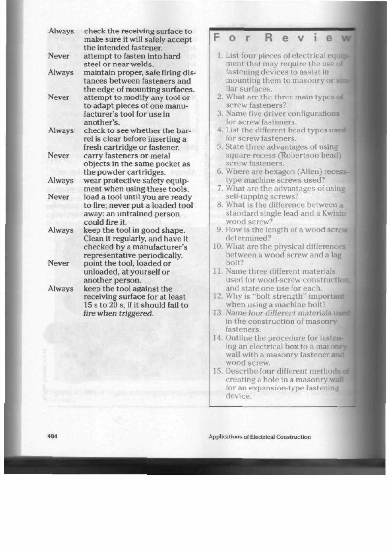
8/19/2019 Applications Electrical
http://slidepdf.com/reader/full/applications-electrical 409/447
Always check the receiving surface to
make sure it will safely accept
the intended fastener.
Never attem pt to fasten into hard
steel or near welds.
Always maintain prop er, safe firing dis
tances between fasteners and
the edge of mounting surfaces.
Never atte m pt to modify any tool or
to ada pt piec es of one manu
facturer's tool for use in
another 's .
Always check to see wh ether the bar
rel is clear before inserting a
fresh cartridge or fastener.
Never car ry fasteners or metal
objects in the s am e pocket as
the pow der cartridges.
Always wea r pro tectiv e safety equ ip
ment when using these tools .
Never load a tool until you are ready
to fire; never pu t a loaded tool
away: an untrained pers on
could fire it.
Always keep th e tool in good sh ap e.
Clean it regularly, and have it
checked by a manufacturer's
representative periodically.
Never point th e tool, loaded or
unloaded, at yourself or
another person.
Always keep the tool against the
receiving surface for at least
15 s to 20 s, if it should fail to
fire when triggered.
F o r R e v
i e w
1. List four pieces of electrical
eqi
ment that m ay require the use <
fastening devices to assist in
mounting them to masonry or
ilar
surfaces.
2. What are the three main type s i
screw fasteners?
3.
Name five driver configurations
for screw fasteners.
4.
List the different head types
ust
for screw fasteners.
5. State three advantages of using
square-recess (Robertson head)
screw fasteners.
6. Where are hexagon (Allen)
re«
type machine screws used?
7. What are th e adv antag es of using
self-tapping screws?
8. What is the difference between a
standard single lead and a Kwixin
wood screw?
9. How is the length of a wood screw
determined?
10.
What are the phy sical differences
between a wood screw and a lag
bolt?
11.
Name thr ee different ma terials
used for wood-screw construction
and state one use for each.
12.
Why is "bolt strength" imports
when using a machine bolt?
13.
Nam e four different ma terials
in the construction of m asonry
fasteners.
14.
Outline the procedure for fasten
ing an electrical box to a mas or
wall with a m aso nry fastener i
wood screw.
15. Describe four different methods"
creating a hole in a ma sonry v.
for an expansion-type fastening
device.
•101
Applications of Electrical Construction

8/19/2019 Applications Electrical
http://slidepdf.com/reader/full/applications-electrical 410/447
16. Name two types of hollow-wall
fasteners an d give one app lication
of each.
17. State three adva ntages of a power-
actuated fastening system.
18.
Why is a licence ne ces sar y for
operating powder-actuated fasten
ing systems?
19. List th e cartridg e and c harg e iden
tifications for low-velocity fasten
ing system s.
20. Explain why a threaded stud is
used to mount equipment, rather
than a d rive pin.
21.
How does a threaded stud for steel
differ from a masonry stud?
22. List three precautions to be taken
when driving fasteners into steel
surfaces.
23. What is the main difference
between the gun mechanisms of a
low-velocity and a high-velocity
tool?
24. What safety equipment is needed
by the operator of a pow der-
actuated tool?
25.
What is the calibre of the powder
cartrid ges used in high- and low-
velocity tools?
Fastening Devices
405

8/19/2019 Applications Electrical
http://slidepdf.com/reader/full/applications-electrical 411/447
Tools of the
Electrical
Trade
E
ach t rad e or skill area h as sp ecial
ized tools designed for safety and
eas e of use, and the electrical trade is no
exception. Over many years, the tool
manufacturing industry has provided a
wide variety of both hand and power
tools to help both amateur and skilled
professional electricians perform their
tasks effectively.
Tool Quality
In
toda y's m arketplace, tools are availa
ble in many p rice ra nge s. As a g eneral
rule, higher quality tools tend to be in
the higher price ranges. Their cost is
often the result of extensive research by
the manufacturer, higher quality materi
als used, more elabora te manufacturing
processe s, and unique or patented
design features.
Many professionals have listened to
part-time tool us ers explain why they
refuse to buy th e more expensive but
highe r quality too ls. All to o frequently,
inexperienced part-time tool users
abuse , overwork, or prematurely wear
out th e lower quality tools they have
cho sen. They have practised false econ
omy, because now they hav e to pur
cha se tools again to complete what they
have started.
Consider, too, that low-quality
tool
material and poor design features oftea
put great stres s on the tool and the oper
ator. Even the experie nced professional
will notice an increa se in physical stress
frustration, a nd wo rk time when using
equipment not designed for the job at
han d. This fact alone would suggest
that
quality tools are essential to both the
training and continuing development of
apprentices and professionals
alike.
High-quality, well-designed too ls
hav e a well-balanced, easy-to-use "feel'
when handled. Tools with comfortable
grips designed to fit the human hand
with minimal discomfort indicate care
and attention to detail on the part of tta
manufacturer. Improperly designed t<
can not only tire out the operator pr
turely, but place him or her in physica
danger.
Tool users vary in height, weight
and arm and h and size, so the tools tta
select should take their physical diffe
ences into account, as well as the
requirem ents of the task at hand. Ha
-
.
pro per too l size will prevent many
accidents caused by exposure to a
tc
that is simply too powerful for a pera
to control safely.
406
Applications of Electrical C onstruction

8/19/2019 Applications Electrical
http://slidepdf.com/reader/full/applications-electrical 412/447
The Driver Family of
Hand T ools
The electrician relies heavily on a vari
ety of tools designed to sec ure equip
ment in place and /or install co ndu ctors
into terminal points or connections.
Drivers in a nu m be r of different ty pe s
and sizes are available. Chapter
21
of
this text illustrates many of the driver
configurations encountered by the
installer (See Fig. 21.2)
Standard Slot Screwdriver. This
versatile driver is used primarily for the
installation of woo d and metal screw s
having a slotted head . Many sizes are
produc ed for the electrician.
An electrician's screwdriver should
have a strong plastic han dle ca pable of
handling the physical stress associated
with normal u se.
A
plastic hand le is also
desirable because it is safe for operation
on or around live equip m ent. Some
man ufacturers provide cushion grips of
rubber on th e handles of their
screwdrivers, thereby preventing the
buildup of blisters and callouses on th e
hand, as well.
Large diam eter ha ndles are normally
indications of high-quality steel in the
blade and sh ank. Steel quality is impor
tant because hand torque is transferred
directly to the blade. (See Fig. 22.1)
Blades should be specially heat tre ated
to the proper hardness and temper to
ensure that they have maximum
strength and useful life span.
For bo th t he safety of th e installer
and pro per screw tension, the screw
driver's blad e should fit th e slot of t he
fastener. (See Fig. 22.3) This pr ev en ts
damage to the fastener's slot as well as
possible injury to th e user's hand or sur
rounding equipm ent sho uld th e tip slip
out of th e slo t.
F I G U R E 2 2 . 1
blade
heavy-duty
square blade
Slot screwdr iver wi th a round
C omfort grip of rubber is locked
around a slotted plastic handle.
specially
heat-treated
tip
Bolster provides
reinforcement
for hard use.
impact-
resistant
plastic handle
F IG U RE 22 .2 Heavy-du ty s l o t screwdr i ver
wi th a square b lade
F IG URE 22 .3
safety.
Blades must
fit—and fill—
the screw
slot.
Proper t ip size is a must for
Blades are produce d in bo th round
and square sha pes to provide the
required strength for
heavy-duty
opera
tions.
(See Fig. 22.2)
Slot Screwdriver Maintenance. Even
top quality drivers will eventually wear
or chip at th e corn ers. This condition
frequently causes damage to the screw
slot, needless slip-out of the screwd river
from th e slot, and personal injury to th e
user. For the m ost efficient use of th e
driver, be sure to keep tip edges straight
Tools of th e Electrical Trad e
407

8/19/2019 Applications Electrical
http://slidepdf.com/reader/full/applications-electrical 413/447
Tip edges should
be sharp and complete.
Broken or worn edges
should be reground or
filed
to a new -like shape.
FIGURE 22.4 P roper care of the tip
improves driver efficiency and the personal
safety of the user.
FIGURE 22.5 P roper tip thickness and
shape are most important for safe and
efficient driver use.
and crisp . (See Fig. 22.4) Reshaping the
tip with a sm oo th hand file or a grinding
wheel will achieve t his.
Great ca re mus t b e taken if a po wer
grinder is used. Overhea ting th e tip will
destroy its hard nes s/tem per ratio, allow
ing the blade to bend each time high
torq ue is applied to th e screwdriver. A
clear indication of heat damage is tip
Phillips
o
o
orx
Square-tip
FIGURE 22.6 The four most comm on
tip configurations
discolouration. T he tip will change to a
straw colour to brown and to b lue.
When resha ping the tip, cold water
for the tip 's rapid cooling should be kept
in a container close to the grinding
wheel. The tip can be dipped in the
wa ter every few sec on ds to help control
tem pera ture rises while grinding.
In addition to sharp, crisp tip edges,
thickness is essential for safe and effi
cient screwdriver performance. A prop
erly ground tip will have a gradual tape r |
when viewed from the side. (See Fig.
22.5) Excessive tip thickn ess preve nts
th e tip from fully e ntering t he fastener
slot and can result in dam age to the fas
tener and poo r torq ue application. Ove»-
grinding and thinning of the tip will
weaken the blade and can lead to break
age of the d river's tip, as well as dam age
to the fastener and /or the surrounding
material.
Screwdrivers are produ ced in a
4 0 8
Applications of Electrical Construction

8/19/2019 Applications Electrical
http://slidepdf.com/reader/full/applications-electrical 414/447
number of configurations (at the tip)
and the more common sha pes can be
seen in Figure 22.6. Pro ced ure s for main
taining screwdrivers in good co ndition
apply only to th e slot.
Square-tip Screwdriver.
Many
installers prefer squ are-tip screw drivers
when installing equipment because of
the unique "cling" feature of the square
recess screws used with
them—the
screw will remain on th e tip of the driv er
while being installed. This feature ha s
saved many hands from injury and
permitted one-handed driver operation,
an advantage because the second hand
is free to sup po rt th e equipment being
installed. The square-tip driver is
commonly known as a
Robertson
driver.
Robertson drivers (See
Fig.
22.7)
are
colour coded by som e manufacturers for
ease of recognition. A yellow ha nd le indi
cates sizing for No. 3 and No. 4 gauge
screws. The three most comm on colours
of handles are green, for No. 5, No. 6, and
No.
7
gauge sc rew s; red, for N o. 8, No. 9,
and
N o.
10; and black, for th e larg er
No.
12
and N o. 14 gauge scr ew s.
FIGURE 22.8 A P hillips screwdriver, availa
ble in tip sizes of N os. 1 ,2,3 and 4
(B
e
3
FIGURE 22. 9 A Torx screwdriver, produced £
in tip sizes of
T8, T10, T15,
T 20, T25, T27 and §
T 30 8
ma tches the fastener. If not, the screw
driver
will
cam-out of the ind enta tion in
the fastener, causing possible eq uipm ent
dam age o r per son al injury. See Figures
22.8
and
22.9
for th es e two drivers .
Safety Note: In area s near
live
con
ductors , an insulated screw driver blade
is desira ble. U sing a driver w ith one will
prevent sho rt circuits and dangerou s
flashes due to accidental c ontact
between live and grounded pa rts. (See
Fig. 22.10)
URE 22.7 A square-tip or Robertson
ewd river for use w ith square recess
ews. Robertson driver handles are colour
d to indicate tip sizes.
P hillips and Torx Screwdrivers. The
autom otive and electrical appliance
industries use two oth er typ es of
screw drivers, the Phillips and the Torx,
for product assembly, and in recent
years the Torx has become particularly
popular. Care m ust b e taken with a
Phillips driver to ensure that the tip
tr
'ML
FIGURE 22. 10 A n insulated-blade screw
driver for use near live equipment
Multi-Purpose Driver. This clever type
of driver stores several tip configura
tions in a hollowed-out handle. A
mag netic tube or chuck firmly ho lds th e
steel tips in place while th e drive r is
being used. Th e mu lti-purpose driver
replaces many individual drivers and is
an ideal tool for service and repair
pe rso ns w ho are unable to carry large
tool kits to the jo b. (See Fig. 22.11) The
Tools of the E lectrical Tra de
409

8/19/2019 Applications Electrical
http://slidepdf.com/reader/full/applications-electrical 415/447
FIGURE 22.11
screwdriver
A multi-purpose magnetic
tips are made of high-quality steel and
will withstand consid erable torqu e from
th e user. However, du e to its hollow h an
dle and screw-on cap , this d river will not
stand up to as much impact abuse as
some of the other drivers.
Hollow-Shaft Nutdriver.
Many
electrical installations require the use of
a driver cap able of turning a hex he ad
bolt or nut. On occasion, the threa ded
bolt may be lengthy and require a driver
capa ble of fitting o ver t he extr a length of
the bolt. These unique drivers are
available in both metric and imperial
sizes,
and may be obtained with an
insulated shaft for protection near live
circuits.
Nutdrivers are usually purch ased in
sets of approximately seven. Figures
22.12 and 22.13 illustrate th is d river typ e.
Hex Key Driver. An othe r form of
driver, not usually found with a
FIGURE 22.12
a cushion grip
A h ollow-shaft nutdriver w ith §
FIGURE 22.1 3 A n insulated-shaft nutdriver
FIGURE 22.14 A versatile A llen key driv
set
FIGURE 22.15 A set of
" T "
handle, long
reach Allen key drivers
screw-d river h and le, is the hex key,
monly
known am ong installers as an
Allen key.
Hex key drivers are frequently
used to secu re pulleys to motor shafts,
as well as terminal scre w s in large main
service panels and equipment.
A
conve
nient set of nine can be seen in Figure
22.14. These drivers are produced in
both metric and
imperial
sizes.
410
Applications of Electrical Construction

8/19/2019 Applications Electrical
http://slidepdf.com/reader/full/applications-electrical 416/447
Large handles, as on the "T " handle
un its in Figure 22.15, can b e mo st useful
when w orking on large service panels.
Having your han ds o utside of the box
and clear of sharp metal edges can be a
genuine safety feature. "T" handle units
can be purchased individually or in sets,
with a large plastic grip hand le ava ilable
for hand comfort and extra torq ue when
tightening.
T he Plier Family of
Hand T ools
The cutting and shaping of c ond ucto rs
when securing them to electrical equip
ment terminals has caused many types
of pliers to be dev elop ed. Each type is
uniq ue in its design features and is pro
duced to perform specific operations.
Installers usually have a variety of typ es
and sizes in their tool kits, their choice
based on personal preference and the
type of work they expect to perform.
Several manufacturers produce high-
quality pliers, and m any installers have a
nam e brand they like more than th e oth
ers. Pliers, after all, are an ex tens ion of
the hum an hand, and installers want
tools that will fit their hands and feel
right when being used.
Side Cutting Pliers.
Side cutters, as
they are commonly known, are one of
the most common types of pliers. They
are so named because their cutting
edges a re located on one side of th e
plier. Side cu tter s g rip fish ta pe s, tw ist
con duc tors to form splices, cut and trim
con duc tors to length, and hold nut an d
bolt fasteners while being tightened.
They are produ ced in a variety of
sizes, ran ging from 6 4 in. to 9'/4 in.
(15.9 cm to 23.5 cm ). The larger mo dels
are frequently referred to as "lineman's
pliers"
bec ause of their popularity with
wire cutter-
__ ,
cen tre of pivot pin
Standard side cutters have the pivot pin
located approximately twice as far from
the cutter (dimension A) as the high
leverage models, providing less
cutting pressure.
wire
cutter
, , — centre of pivot pin
Distance "A " on high leverage models is
less,
providing twice the cutting pressure.
FIGURE 22.16 C omparison of standard and
high leverage side cutters
the installers of pole and line equipment.
High-leverage m odels are available in
certain larger sizes. In the se pliers, the
pivot point is located closer to the tool's
cutting edge. This feature nearly doubles
the ease of cutting large diameter con
duc tors in the No. 3 or No. 2
AWG
range
of sizes. (See Fig. 22.16)
High-quality pliers a re forged, pro
portioned, shaped, hardened and tem
pered so that the handles have a certain
amount of
flex
or bend. This characteris
tic prev ents excessive hand strain to the
operator. (See Fig. 22.17) Modern cutting
edges are specially tough and hard, with
som e com panies using laser technology
in hardening to provide the user with
yea rs of reliable servic e from the tool.
Tools of the Electrical Trade
411

8/19/2019 Applications Electrical
http://slidepdf.com/reader/full/applications-electrical 417/447
FIGURE 22.17 High leverage side cutting
pliers with comfort-grip handles
FIGURE 22.18 C hoosing pliers based on the
size of the user's hand ensures safe and effi
cient operation.
Pliers, like many other tools, should
be purchased to fit the hand size of the
owner, as well as to me et job req uire
ments. Figure 22.18 illustrates a pair of
high leverage side cutte rs well m atched
to the hand of the user.
Plastic comfort-grips are fitted to the
handles of many pliers to p rovide a
higher degree of user comfort. T hese
handles can lessen hand strain but often
lower the degree of cutting/gripping
power th e tool is able to provide. The
softness and "give" of the plastic used is
the ca us e. An analogy is that if you w ere
to weigh yourself on a bathroom scale
placed over a soft carpet, you would get
a different reading tha n if the sca le was
placed on a firm surface . Plastic grips
tend to enlarge the handle size of pliers,
which can b e a disadvantage to an
ow ner with a smaller h and.
Plastic grips should not be
considered
or treated as an
insulating feature
when
working with live wires. Tiny ho les or
cuts in the soft plastic render the tool
dangerous if only the handle is used to
isolate the user from a potential shock
hazard on an installation or repair. Plas
tic grips were not designed by the m anu
facturer for this purpose, and were
therefore not tested an d approve d for
shock protection.
Many electricians have found that
cutting tw o or mo re live wires at the
sam e time will pro du ce a short-circuit
curren t at the cutting edge. Care must be
taken to prevent this because the cur
rent will burn a hole right through the
cutter, destroying the usefulness of a
fine tool.
Diagonal Cutting Pliers. Th ese pliers
are intended for one purp ose, tha t is, to
cut wire and cab le. In the ha nd s of an
experienced installer, they can do much
more than trim conductors to length.
They can cut small bolts, trim the
sheathes of both nonmetallic and
armoured cables, prepare and trim
power tool cords, clean up e xcess
strands from terminal connections, and
form t he lo op in wires for term inal
screw s. They are particularly suited to
work in confined are as, where th e larger
side cutting pliers cannot b e used
effectively. Over the years, skilled
electricians have invented other uses
for
the se versatile cu tters , as well.
Similar to oth er typ es of pliers, diag
onal cut ters are available in various
sizes an d len gths, ranging from
4 4
in.
(11
cm ) to 8 in. (20 c m ). (See Figs. 22.19.
22.20 an d
22.21)
Both regular and high-
leverage models are available, using the
same design features produced on the
side cutters. Plastic comfort-grips are
provided by some manufacturers to
412 Application s of Electrical Con struction

8/19/2019 Applications Electrical
http://slidepdf.com/reader/full/applications-electrical 418/447
FIGURE 22.19
General purpose diagonal
cutter for use with electronic and small
con
ductor circuits
FIGURE 22. 20
S tandard leverage general
purpose diagonal cutter
c
s
FIGURE
22.21
High leverage diagonal
cutters provide approximately one-third more
cutting pressure than standard mod els.
lessen han d str ess w hile using the tool.
Figure 22.22 illustrate s diago nal cu tter
operation.
Cable Cutters. Electrical cab les are
frequently assembled from multiple
strands of copper or aluminum wire.
(See Chapter Five.) Special
cable-cutting
tools allow an installer to cut o r trim
these larger conductors effectively.
Figure 22.23 illustrates a hand-operated
cutter, capable of trimming soft copper
cables up to
N o.
2/0 AWG. The str an ds
are kept in a nea t, close configuration for
easy insertion into a terminal block o r
con nec tor. Figure 22.24 illustrates a
compound lever-action cutter which
uses a ratchet assembly to provide
FIGURE 22.22 Use of diagonal cutting pliers
in a confined cable trough
FIGURE 22.23 Hand-operated cable cutter
FIGURE 22. 24 C ompound action ratchet
drive cable cutter
additional cutting force on soft copper
con duc tors up to 350 MCM. These
light
weight single-handed too ls can be car
ried in a stand ard tool po uch .
Figure 22.25 sho w s a two-h anded ,
32 in. (82 mm ) long-han dled, she ar-ty pe
cutter for copper and aluminum cables
Tools of the Electrical Trade
413

8/19/2019 Applications Electrical
http://slidepdf.com/reader/full/applications-electrical 419/447
FIGURE 22.25 Heavy-duty, two-h and ed cable cutter w ith fibreglass handles and rubber grips
up to 1000 MCM. Insu lated, fibreglass
handles ease the strain of operation,
while providing som e degree of pro tec
tion to the operator from live circuits.
The cutting tips can be replaced when
the y are too w orn for effective u se . This
tool was not designed to cut steel cables
or b olts. If it is used in this way, dam age
to the tool will result. The curved cutte r
design perm its an extremely neat cu t on
a cable, thereb y easing the task of insert
ing the cable into a termin al fitting.
Needle N os e Pliers. Needle
or
long
nose
pliers, as they are som etimes
called, give the installer or service
technician an extended reach into areas
or crevices where th e fingers cann ot
approach safely or effectively. They are
used to form loops on con du ctors for
termination, retrieve fallen or misplaced
parts,
hold small parts effectively for
installation, and assist in the tightening
of nuts and bolts. Num erous sizes are
available, with or without c utters , and
can be equipped by manufacturers with
comfort-grip plastic handles. Figures
22.26 and 22.27 illustrate this small but
versatile tool.
Many variations of these pliers are
prod uced . Some are equipped with wire
stripping no tche s, and som e have flat,
concave, or curved nose designs for spe
cial applications. Standard and long-
reach designs have been produced to
give installers and tec hnician s a tool to
meet any task they face.
FIGURE 22.26 S mall, 4 % in. (121 mm)
cutting long-nose pliers with comfort-grip
handles
FIGURE 22.27 Heavy-duty long-nose plier
in an 8Vi in . (211 mm) length, with comfort-
grip handles and wire-cutting jaws
Pump Pliers.
Pump pliers are another
highly useful tool in an electrician's kit
or pou ch. These pliers are to the
electrician w hat a pipe wrench is to the
plumber. The jaws are specially
designed to grip cond uit, fittings,
bolts,
nuts,
etc., in such a way tha t the re is an
abso lute m inimum of slippage when
torq ue is applied. The jaws are
positioned and locked into place by a
slanted tongue
which fits into a m atching
groove in the opposite handle.
A
wide
rang e of jaw open ings are available, and
the tong ue and groove feature ensure s
that the sett ing cannot change un der
the
heaviest pre ssu re of use.
414
Applications of Electrical C onstruction
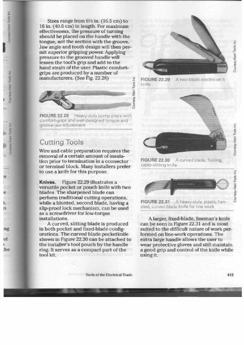
8/19/2019 Applications Electrical
http://slidepdf.com/reader/full/applications-electrical 420/447
Sizes ran ge from 6'/2 in.
(16.5
cm) to
16 in. (40.6 cm) in length . For maxim um
effectiveness, the pressure of turning
should be placed on the handle with the
tongue, not the section with the groove.
Jaw angle and t oo th design will the n per
mit supe rior gripping power. Applying
pressure to the grooved handle
will
lessen the tool's grip and add to th e
hand strain of th e user. Plastic comfort-
grips are produced by a number of
manufacturers. (See Fig. 22.28)
0)
FIGURE 22.28 Heavy-duty pump pliers w ith
comfort-grips and well-designed tongue and
groove jaw adjustment
C utting T ools
Wire and cable prepara tion re quires the
removal of a certain amount of insula
tion prior to termination in a conn ector
or terminal block. Many installers prefer
to us e a knife for this pu rpo se.
Knives. Figure 22.29 illu stra tes a
versatile pocket or pouch knife with two
blades. The sharpened blade can
perform traditional cutting operations,
while a blunted, seco nd blade, having a
slip-proof lock mec hanism, can be used
as a screwdriver for low-torque
installations.
A
curved, slitting blade is produc ed
in both pocket and fixed-blade config
uration s. Th e curv ed b lade pocketknife
show n in Figure 22.30 can be attac he d to
the installer's tool pouch by the handle
ring. It ser ve s as a com pac t part of th e
tool kit.
FIGURE 22.29
knife
A two-blade electrician's
FIGURE 22.30 A curved blade, folding,
cable-slitting knife
FIGURE 22.31 A heavy-duty, plastic
han
dled,
curved blade knife for line work
A larger, fixed-blade, line man's knife
can b e seen in Figure
22.31
and is m ost
suited to the difficult nature of work per
formed on line-work operations. The
extra large handle allows the us er to
wear protective gloves and still maintain
a good g rip and co ntrol of the knife while
using it.
Tools of the Electrical Trade
41

8/19/2019 Applications Electrical
http://slidepdf.com/reader/full/applications-electrical 421/447
FIGURE 22.32 A cable splicing kit consist
ing of a knife, scissors and pouch
Cable splicers and other installers of
small con du ctor cables make use of a
versatile scissor/knife kit. The scisso rs
are notched on the up per p art of the
blade to assist in the stripping of small
wires, and th e tw o units fit snug ly into a
pouch designed for the purpose. (See
Fig. 22.32)
Hacksaw.
Condu it op era tion s of all
size require the frequent use of a
metal-cutting hacksaw. The heavy-duty
mo del sho wn in Figure 22.33 has a
square-tube frame that holds spare
blad es for the installer. Blade tension is
adjusted by a wing-nut unit at the base
of the h andle: tension should be regu
lated to prevent u ndue b ending of the
blade while cutting.
Blades are prod uced in a wide range
of lengths and qualities to suit the saw
and task at hand. Both carbo n and high
speed steel blades are available from a
number of manufacturers.
The necessary number of teeth per
inch of blad e is determ ined by the thick
ne ss of the m aterial being cut. Thin
materials such as thinwall conduit and
armoured cable benefit from blades hav
ing 32 tee th pe r inch. Rigid con duit and
general cutting ope rations frequently
require the 24 tooth per inch blade.
Triple Tapping Tool. Installers
frequently have to clean up thread ed
holes in boxes and fittings which have
become clogged or damaged during the
con structio n pro ces s. A most useful tool
for this ta sk is pic ture d in Figure 22.34.
Its screwdriver-like design permits
one-handed operation. The most
commonly used thre ads, No.
6-32
tpi,
No. 8-32 tpi, and No. 10-32 tpi, a re
mac hined o nto the blade/shaft of the
unit.
FIGURE 22.34 A triple tapping tool for
repairing damaged No. 6-32 tpi, No. 8-32 tp
and No. 10-32 tpi threads found in m ost el'
trical equipment
FIGURE 22.33
frame hacksaw
A heavy-duty, square-tube
The b lade, m ade of high-quality tool
steel, can be b roken easily if not held at
a 90° angle to th e work, or if subje cted to
extreme torq ue d uring its use. Blades
can b e replaced if nece ssary.
416
Applications of Electrical Construction

8/19/2019 Applications Electrical
http://slidepdf.com/reader/full/applications-electrical 422/447
Scratch Awl.
On many occasions,
electricians h ave to m ake hole s in m etal
and m ust first mark whe re the h oles
should b e. The awl, with
its
hardened,
sha rpe ne d steel point, is a tool m ost
suitable for this task. W hen h and held, it
is cap ab le of scribing a c lean, fine line on
a metal surface.
Many installations take place on or
over metal,
preformed-pan
ceilings,
metal stud s, and oth er lightweight shee t
metal products . Sheet metal screws (see
Chapter 21) are frequently used to
secu re boxes and cables to these sur
faces.
Starting holes for the screw s can
be m ade by striking the awl with a ham
mer and driving it into the sh eet m etal. A
heavy-duty m odel is pictured in Figure
22.35.
Plastic-handled models are produced
by several ma nufacturers for lighter
duty operat ions.
FIGURE 22.35 Heavy-duty scratch aw l
S triking T ools
Hammers form a major part of an electri
cian's tool kit. They are invaluable when
installing equipment with nails, fasten
ing cable with stap les, or creating holes
in m aso nry w alls or surfaces. Several
types have been produced to meet spe
cific job requirements.
Claw Hammer.
Claw hamm ers are
m ost useful for work on woo den frame
structu res. They drive and remove nails ,
staples, and other fasteners with a
minimum of strain on the op erator. O ne
claw ham me r, show n in Figure 22.36, has
been designed with the electrician in
mind. It has a non-conducting fibreglass
handle—a strong , shock -absorb ent sha
tha t will survive many ye ars of h ard
work, ft afso ha s a perforate d ru bb er
handle, a feature on som e claw ham me r
that provides th e user with a sure and
safe g rip. Claw ham m ers are pro duc ed in
a variety of head w eights, with the mo st
com mo n sizes being 16 oz. (454 g) and
20 oz. (567 g).
FIGURE 22.36 A straight claw, fibreglass
handled,
electrician's hammer with perforate
rubber grip
FIGURE 22.37
hammer
A w ood en handled ball pe
Ball Peen Hammer.
The ba ll peen o r
"ma chinist 's" ham mer is produced in
th e widest range of head w eights, the se
being 8 oz. (227 g ), 12 oz. (340 g), 16 oz.
(454 g), 24 oz. (680 g) an d 32 oz. (907 g).
Ball peen hammers are ideal for
heavy-duty striking operations such as
cutting with a cold chisel, p roduc ing
hole s in con cre te surfaces, o r driving
assorted fasteners into place with heavy
blows. Th ese h am m ers, one of which is
show n in Figure 22.37, are usually
equipped with strong wooden hand les.
Tools of the Electrical Trade
41
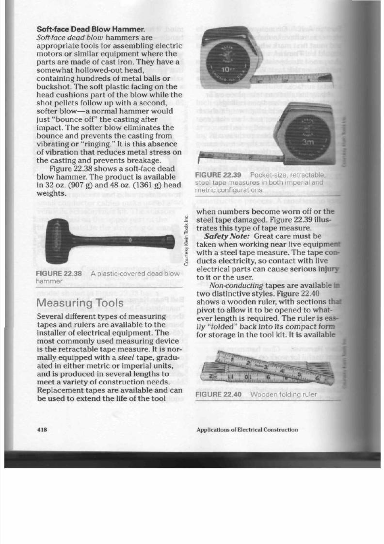
8/19/2019 Applications Electrical
http://slidepdf.com/reader/full/applications-electrical 423/447
Soft - face Dead Blow Hammer.
Soft-face dead blow
hamm ers are
app ropria te tools for assembling electric
motors or similar equipment where the
parts are made of cast iron. They have a
somewhat
hollowed-out
head,
containing hun dre ds of metal balls or
buckshot. The soft plastic facing on the
head c ushio ns pa rt of the blow while the
shot pellets follow up with a second,
softer
blow—a
normal hammer would
just "bounce off" the casting after
impact. The softer blow eliminates the
bounce and prevents the casting from
vibra ting or "ringing." It is this ab se nc e
of vibration that reduces metal stress on
the casting and prevents breakage.
Figure 22.38 sho w s a soft-face dead
blow hammer. The product is available
in 32 oz. (907 g) an d 48 oz. (1361 g) head
weights.
r -
FIGURE 22.3 9
P ocket-size, retractable,
steel tape measures in both imperial and
metric configurations
FIGURE 22.38
hammer
A plastic-covered dead blow
Measuring Tools
Several different typ es of m easurin g
tapes and rulers are available to the
installer of electrical equipment. The
most comm only used measuring device
is the re tractab le tap e m easure . It is nor
mally equipped with a
steel
tape, gradu
ated in either metric or imperial units,
and is prod uced in several lengths to
meet a variety of construc tion nee ds.
Replacement tap es are available and can
be used to exten d th e life of th e tool
when numbers become worn off or the
steel t ap e dam aged . Figure 22.39 illus
trates this type of tape measure.
Safety Note:
Great care must be
taken when working near live equipment
with a steel tape m easure. The tape con
ducts electricity, so contact with live
electrical parts can cause serious injury
to it or th e user.
Non<onducting
tap es a re available in
two d istinctive styles . Figure 22.40
show s a wo oden ruler, with sections thai
pivot to allow it to be op ene d to what
ever length is required. The ruler is eas
ily "folded" bac k into its com pac t form
for storage in the tool kit. It is available
FIGURE 22. 40
W ooden folding ruler
418
Applications of Electrical Construction

8/19/2019 Applications Electrical
http://slidepdf.com/reader/full/applications-electrical 424/447
in both imperial and metric measure,
that
is,
in both 6 ft. and 2 m lengths.
Frequently an installer must measure
longer d istances when laying out a job
or estimating lengths of m aterial to be
used. Another tape measure, with a tape
of either non-conducting fabric or of
steel, is available in lengths of
50
ft. and
100
ft. and in lengths of
15
m,
25 m,
and
30
m.
Figure 22.41 illustrates this type of
measuring device.
FIGURE
22.41
N on-conducting fabric tape
measure and reel
S afety E quipment
Electricians or lineworkers spend a con
siderable amount of installation time
working from ladders, building struc
tures, or outdoor poles. To protect them
from falls and decrease their fatigue,
safety belts and harnesses have been
developed.
Figure 22.42 illustrates a safety belt,
made from a tough nylon m aterial and
equipped with drop-forged tongue buck
les and "D" rings. This belt is not
intended to support the worker while
performing
a
task,
but to act as a fall pre
vention device should the worker lose
his or her footing or grip during the job.
Strong,
5
/8 in. (16 mm) nylon rope is
recommended for use with the belt. This
safety line should be secured properly
FIGURE 22.42 N on-supporting, nylon mesh
safety b elt, for use w ith sturdy safety lines
to both the belt and a structure near the
worker that could withstand the stress
that would be placed on both the belt
and th e rope if the worker slipped and
fell.
Special features are required in a
body belt meant to supp ort the w orker's
weight while the job is being performed.
Additional stre ss from body movements,
pulling, tugging, twisting, and lifting
must be handled by these belts. Figure
22.43 illustrates this belt type.
Figure 22.44 illustrates the adjustable
type of pole strap frequently used when
the installer or lineworker is using the
belt to support his or her weight.
Figure 22.45 illustrates a far more
supportive belt that can provide addi
tional back support to the
worker.
This
belt is intended to reduce the physical
stress and fatigue of the user who may
be in it for extended periods of time.
Lockout Device.
Great care must be
taken when working on or around live
equipment or machines that could start
up without notice. To prevent injury
from these sources, installers frequently
place a padlock on the main power
switch supplying current to the
equipment being worked on. When a
number of trades are required to work
on one machine at the same time, each
worker needs control over the start-up
of the machine or equipment.
Figure 22.46 illustrates a device
designed to give a worker such protection
Tools of the Electrical Trade
419
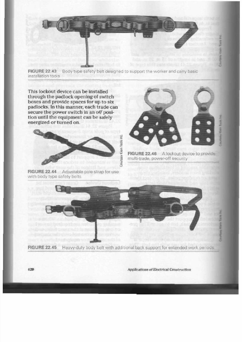
8/19/2019 Applications Electrical
http://slidepdf.com/reader/full/applications-electrical 425/447
FIGURE 22.43 Body type safety belt designed to support the worker and carry basic
installation to ols
This lockout device can be installed
through th e padlock opening of switch
boxes and provide spaces for up to six
padlocks. In this manner, each trade can
secure the power switch in an
off
posi
tion until the equipm ent can be safely
energized or turned on.
| FIGURE 22.46 A lockout device to provide
| mu lti-trade, pow er-off security
FIGURE 22.44 A djustable pole strap for use
with body type safety belts
FIGURE 22.45 Heavy-duty body belt w ith additional back support for extended work periods
420
App lications of Electrical Co nstruction

8/19/2019 Applications Electrical
http://slidepdf.com/reader/full/applications-electrical 426/447
Tool Pouches and Kits
Several manufacturers produce leather
tool-carrying pouc hes tha t provide the
installer with a convenient me thod of
keeping the tools close at hand. Figures
22.47 and 22.48 illustra te tw o of t he
many designs available.
When filled with tools , th es e
po uch es are very heavy, so only those of
the best quality materials and
workman
ship should be considered w hen making
a p urc has e; lightweight, low-quality
pou ches will soon wear out and be com e
both a nuisance and a work hazard. A
wide, strong belt m atched to th e us er's
S
waist size should also be chosen for use
with a pouch.
Figure 22.49 illustrates some of the
tools frequently carried by installers in
their pouch es. Although pouche s are
usually purchas ed separa tely from tools,
on occasion, a manufacturer or tool sup
plier will offer a "package
deed"
whereby
the tools and a carrying pouch are
included in the purc hase price.
A high-quality tool kit, con sisting
of
tools and pouch, costs a considerable
sum of money, so care should be taken
not to shorten its useful life. Exposure to
we tness, extremes of heat, and corrosive
chemicals can ruin this valuable work
aid.
Holster-style
pouches are also availa
ble. Designed for user s of portable, bat
tery-operated drills and screwdriver-
type tools, thes e pou ches help overcome
FIGURE 22.47 A three-pocket tool pouch
with screwdriver support loops and tape
holder
FIGURE 22.48 A versati le pouch with a vari
ety of external tool sleeves, tape holder and
knife-holding snap clip
Tools o( the Electrical Trade 421

8/19/2019 Applications Electrical
http://slidepdf.com/reader/full/applications-electrical 427/447
2
o
•c
LU
5
o
FIGURE 22.49 Some of the many hand
tools normally carried by installers or service
personnel in their tool pouches
FIGURE 22.50 A holster-style pouch with
com partme nts for a spare battery and bits, f<
use with battery-operated drill/driver tools
the problems of looking after tools when
not in immediate
use,
particularly if
someone is working from a ladder or
other support platform height.
Figure 22.50 illustrates a quality hol
ster-style pouch capable of supporting
the tool, extra
bits,
and spare battery
when needed. A leather thong has been
provided to secure the pouch to th e
user's leg and prevent it from bouncing
or flopping about when climbing
ladders, etc.
P ortable P ower T ools
For many years, po rtable, electric power
tools have been a major factor in both
the construction and service industries.
These tools have undergone immense
improvement over the years , as job
requirements and tool technology have
developed. New products are constantly
being designed and m ade available to
the consumer. They offer the potential
owner a wide variety of
styles,
sizes, and
features.
Quality
and
Cost.
As with hand tools,
the quality of power tools greatly affects
their reliable term of use. Lower quality
tools (often reflected by a lower
purchase price) may appear attractive
to th e inexperienced user. However they
seldom provide the balance, comfort of
use, reliability, and pow er/torque
required to complete a demanding task.
The most expensive tool is not
necessarily the best for the
job,
but cost
does provide some indication of design
forethought, materials used, and the
guarantee provided by the
manufacturer.
422
Applications of Electrical Construction
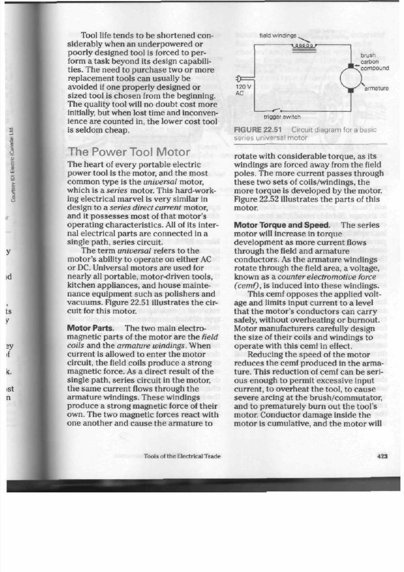
8/19/2019 Applications Electrical
http://slidepdf.com/reader/full/applications-electrical 428/447
Tool life tends to be shorten ed con
siderably when
an
underpowered
or
poo rly designed tool is forced to per
form
a
task b eyond its design cap abili
ties. The need to purchase two or more
replacement tools can usually be
avoided if one prop erly designed or
sized tool
is
cho sen from th e beginning.
The quality tool will no do ubt cost mo re
initially, but when lost time and inconven
ience are counted in, the lower cost tool
is seldom ch eap.
T he Power T ool Mo tor
The heart
of
every po rtable electric
power tool is the motor, and the m ost
comm on typ e is the universal motor,
which is
a series
motor. This hard-work
ing electrical m arvel is ver y similar in
design
to a
series direct current m otor,
and it possesses most of that mo tor's
operating chara cteristics. All of its inter
nal electrical parts are connected in
a
single path, series circuit.
The term
universal
refers to
the
m otor's ability to opera te on either AC
or DC. Universal mo tors are used for
nearly all portable,
motor-driven
tools,
kitchen appliances, and hous e mainte
nance equipment such as polishers and
vacuums. Figure 22.51 illustrates th e cir
cuit for this motor.
Motor Parts.
The two main electro
magnetic pa rts of the m otor are the field
coils
and th e
armature windings.
When
current is allowed
to
enter the motor
circuit, the field coils prod uc e a strong
mag netic force. As
a
direct result
of
the
single path, series circuit in the motor,
the sam e current flows through the
arm ature w indings. The se windings
produce a stron g m agnetic force of the ir
own. Th e two m agnetic forces reac t w ith
one another and cause the armature
to
f ield windings
VAMflJLT
brush
carbon
compoun
0=^
120V
A C
,J*Tcompoun
^ g '
armatu
trigger switch
FIGURE 22.51 Circuit diagram for a basic
series universal motor
rotate with considerable torque, as its
windings are forced away from the field
poles. The more current passes through
thes e two sets of coils/windings, the
more torq ue is developed by the motor.
Figure 22.52 illustrates the pa rts of this
motor.
Motor Torque and S pee d. The series
motor will increase in torque
development as mo re curre nt flows
through the field and armature
con du ctor s. As the a rma ture windings
rot ate thro ug h th e field area , a voltage,
known
as a
counter electromotive force
(cemf),
is
induced into these w indings.
This cemf opposes the applied volt
age and limits input current
to a
level
that the motor 's conducto rs can carry
safely, w ithout ov erhea ting or burnout.
Motor manufacturers carefully design
the size of their coils and w indings to
op era te with this cemf in effect.
Reducing the spe ed
of
the mo tor
reduc es the cemf produc ed in the arma
ture. This reduction
of
cemf can be seri
ous enough
to
permit excessive input
current, to overheat the tool, to cause
severe arcing at the brush/comm utator,
and
to
prematurely burn out the tool's
motor. Con ductor dam age inside the
motor is cumulative, and the motor will
Tools
of
the Electrical Trade
42

8/19/2019 Applications Electrical
http://slidepdf.com/reader/full/applications-electrical 429/447
laminated steel
armature core
cooling
fan
armature
shatt
brush connection
springs
armature coils ballbearings
field windings
F I G U R E 2 2 . 5 2 I n t e r n a l p a r t s
of a
u n i v e r s a l m o t o r
power leads
not "heal" or get better when th e tool is
in stor age . For this reason ,
be
sure
to
consider th e quality and current-carry
ing capacity of a motor's windings when
purchasing a power to ol. Most power
tools have
a
current rating stamped
on
their nameplate
to
give the prosp ective
user som e indication of the m otor cur
rent recommended by the manufacturer
for safe and continued use.
Most series motors have
a
cooling
fan attache d to the a rm ature shaft to
assist in th e cooling of the motor and its
conductors. Lower quality
or
light-duty
tools are notorious for having condu c
tors th at a re too few in number or are
undersized. These condu ctors have a
direct influence on the cost and eventual
life span of the too l. Tool o per ator s
should condition themselves to listen to
the motor's normal operating speed and
sound and
to
allow th e too l
to
perform
as much as possible within its usual rpm
rang e. Stalling the m otor or ov erloading
the tool will quickly reduc e its no rmal
operating efficiency and life span: when
speed is reduced, cooling fan efficiency
drops
off
and th e input current rises.
Motor RPM. Series m otor s, by nature-
operate
at
many thousand s
of
revolu
tions per minute (rpm ), and their
arm ature and field curren ts are one and
the sam e. When the m otor is running
without
a
load
on
it, the relationsh ip
between the armature and field
magnetic forces allows the armature to
rotate
at
speeds up
to
25 000 rpm . Any
type
of
load p laced
on
this mo tor
reduces armature speed and increases
the field and ar m ature current. The
increase
in
current causes the m otor
to
develop more torque . This process wii
continu e right up to the po int where the
m otor stalls, and m aximum torq ue is
developed. As mentioned earlier in this
chapter, care mu st be taken not to allow
the speed reduction and current
increase
to
cause overheating and
damage
to
the windings.
Certain tools used
in
the wood
and
i
424
Applications of Electrical Construction
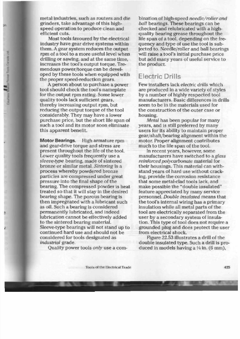
8/19/2019 Applications Electrical
http://slidepdf.com/reader/full/applications-electrical 430/447
metal indus tries, such as routers and die
grinders, take advantage of this
high
speed operation to produce clean and
efficient cuts.
Most tools favoured by th e elec trical
industry have gear drive systems within
them. A gear system reduces the output
rpm of a tool to a more useful level wh en
drilling or sawing, and at the sam e time,
increases the tool's outpu t torq ue. Tre
mendous power/torque can be devel
oped by these tools when equipped with
the proper speed-reduction gears.
A
person abou t to purch ase a power
tool should check the tool's nam eplate
for th e outp ut rpm rating. Some lower
quality tools lack sufficient gears,
thereb y increasing outp ut rpm, but
reducing the ou tput to rque of the tool
considerably. They may have a lower
purchase price, but the short life span of
such a tool and its motor soon eliminate
this apparent benefit.
Motor B earings. High arm ature rpm
and gear-drive torqu e and stress are
pre sen t thro ugh out th e life of the tool.
Lower quality tools frequently use a
sleeve-type bearing, made of sintered
bronze or similar metal.
Sintering
is a
process whereby powdered bronze
particles are compressed under great
pressure into the final shape of the
bearing. The compresse d powd er is heat
treat ed so th at it will stay in th e d esired
bearing shape . The porous bearing is
then impregnated w ith a lubricant such
as oil. Such a bearing is c onsid ered
permanently lubricated, and indeed
lubrication cannot be effectively added
to the sintered bearing material.
Sleeve-type bearing s will not stan d up to
continued hard use and should not be
considered for tools designated as
industrial grade.
Q uality power tools only use a com
bination of high-speed
needle/roller and
ball bearings. The se bearings can b e
checked and relubricated with a high-
quality bearing grease throughout the
life span of a tool, depending on the fre
quency and type of use the tool is sub
jected to. Needle/roller and ball bearings
will raise a tool's initial pu rch ase price
but add m any years of useful s ervic e to
the product.
Electric Drills
Few installers lack electric drills which
are p rodu ced in a wide variety of styles
by a number of highly respected tool
m anufa cturers. Basic differences in drills
seem to be in the materials used for
the con struction of the outer case or
housing.
Metal has been p opular for m any
years, and is still preferred by many
us ers for its ability to m aintain prop er
gear/shaft/bearing alignment within the
motor. Proper alignment contribu tes
much to th e life span of the tool.
In recent y ears, however, some
manufacturers have switched to
a glass
reinforced polycarbonate material for
their housings. This material can with
stand years of hard use without crack
ing, provide the corrosion resistance
that some metal-clad tools lack, and
make possible the "double insulated"
feature app reciated by many service
personnel.
Double insulated
means that
the too l's internal wiring has a primary
insulation while all metal p ar ts of the
tool are electrically separated from the
user by a seco nda ry system of insula
tion. This type of tool do es not r equ ire a
grounded plug and does protect the use
from electrical shock.
Figure 22.53 illus trat es a drill of th e
dou ble insulated typ e. Such a drill is pro
duced in models having a 4 in. (6 mm ),
Tools of the E lectrical Trade
42

8/19/2019 Applications Electrical
http://slidepdf.com/reader/full/applications-electrical 431/447
F I G U R E 2 2 . 5 3 A % in . (10 mm) var iable
s p e e d
dri l l ,
l i ght t o m ediu m du t y , w i t h a
rev ers ing s w i t c h
3
I
2
Vs in. (10
mm),
or Vi in. (13 mm) capacity
chuck.
Many of these drills are equipped
with additional features, such as varia
ble speed control through the trigger
switch and m otor reversing. The motor
reversing feature aids in removing some
drill bits and allows the tool to be used
as a screwdriver when equipped with
the proper bit. (See Figs. 22.54 and 22.55
for diagrams of m otor reversing cir
cuits.)
Figure 22.56 features a m ore power
ful drill that has been equipped with a
heavy-duty m otor and
Chuck.
The drill is
designed to provide extra torque for
tougher jobs.
half of field winding
\
TJLQJLQJLT
trigger switch
#
120
V A C
double-pole
double-throw switch
^3",
rush
carbon
compound
half of field winding
• \ JU L Q _ Q JL T
FIGU R E 22. 54 A m ot or rev ers ing c i rcu i t us ing a double- po le , doub le- t hrow s w i t c h t o revers e
c urrent d i rec t ion t hrough t he armat ure w ind ings
426
Applications of Electrical C onstruction

8/19/2019 Applications Electrical
http://slidepdf.com/reader/full/applications-electrical 432/447
half of field winding
trigger switch
1
£
120
V A C
AJlMiJjLr
half of field winding
FIGURE 22.55 A n alternate motor reversing circuit show ing direction of current through both
the field coils and armature wind ings
o
FIGURE 22.56 A heavy-duty
3
/
8
in.
(10 mm)
drill with speed control and a reversing sw itch
Safety Note: When using the se tools,
be sure not to grip them carelessly.
Many injuries have resulted when the
operator has not taken care. The drill bit
may jam, causing the tool to rotate in the
opposite direction to the bit and subject
ing the user's wrist to a great deal of
strain. Just as an installer should use the
proper size of hand tool, he or she
should also match power tools to both
the size of the task at hand and personal
size and ability.
Speed control is accomplished by
using a trigger switch with a built-in sili
cone control rectifier circuit (SCR) to reg
ulate the actual voltage that is supplied
to th e field and armature windings. This
trigger switch normally provides
Tools of th e Electrical Tra de
427

8/19/2019 Applications Electrical
http://slidepdf.com/reader/full/applications-electrical 433/447
complete variable speed from zero to
full speed and provides the user with a
much greater degree of control for many
drilling operations.
On many occasions, large holes must
be drilled with high-speed steel drill bits
or hole saws, and they require the power
of a larger, two-handed power drill. Fig
ure 22.57 shows this type of drill. Care
must be taken by the operator to ensure
firm footing, balance, and a secure grip
to prevent injury during use of the tool.
FIGURE 22.57 A two-hande d powe r drill for
heavy cons truction use
Special Purpose Drills.
Electricians are
frequently forced to drill holes in
awkward or confined spaces. Several
specially designed angle drills are
available for these tasks and can be seen
in Figures 22.58, 22.59 and 22.60.
Drilling holes in brick or cement sur
faces can be time consuming and gruel
ling. Masonry drill bits such as those in
Figure 21.39 can be pu t to excellent use
in specially designed power drills that
produce both rotary and reciprocating
FIGURE 22.58 A light-duty angle dril l for
use in confined spaces
§ FIGURE 22.59 A
Vi
in. (13 mm) two sp -
3 angle
drill,
medium duty design, with full
| swivel adjustme nt of chuck direction
FIGURE 22.60 A
V?
in . (13 mm) two speeJ
angle drill, heavy-duty model
motions. As the drill bit rotates, a built-
in hammer feature causes the bit to
move in and out of the cutting surface
at
high speed. This in-and-out action
tends
to break up small stones or similar hard
spo ts in the drilling material, and
quicken the task considerably.
428
Applications of Electrical Co nstruction

8/19/2019 Applications Electrical
http://slidepdf.com/reader/full/applications-electrical 434/447
FIGURE
22.61
A light-duty hammer
dril
with a hole-depth guide
Q.
s
FIGURE 22.62 A variable, tw o speed ham
mer
drill,
medium duty, with dep th guide and
front handle grip
Figure
22.61
show s a light-duty ham
mer drill equipped with a hole-depth
guide to ensure uniform drilling depth.
A medium-duty ham mer drill can be
seen in Figure 22.62. This drill has two
separate speed ranges which can be
controlled from zero to full speed by the
trigger switch. A reversing switch allows
the tool to run in reverse so that it can
remo ve the drill bit and residu e from th e
finished hole. An adjustable handle is fit
ted to th e front sectio n of th e tool to pro
vide a bette r grip and safer control of
the tool when in use.
Both the tool shown in Figure 22.61
and the one sho wn in Figure 22.62 can be
used for straight drilling and hammer
drilling.
Heavy-duty too ls ar e available for
the installer who must drill large holes
into tough maso nry su rfaces. These
tools are also designed to operate for
long perio ds of time without undu e w ear
or o verhe ating. Figure 22.63 illustrates a
heavy-duty hammer drill that is
designed with a special type of chuck to
accept masonry bits only. It cannot be
used as a norm al typ e of drill with a con
ventional chuck.
Owners of hammer drills should peri
odically use an air hose to blow
powdered masonry particles from the
inside of the too l. Eye prote ction shou ld
be worn during all drilling and cleaning
operations.
FIGURE 22.63
rotary hamm er
A variable speed, heavy-duty
Tools of the Electrical Tra de 429
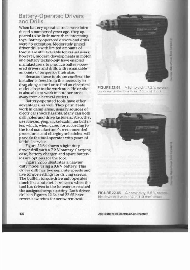
8/19/2019 Applications Electrical
http://slidepdf.com/reader/full/applications-electrical 435/447
Battery-O pe rated Drivers
and Drills
When battery-operated tools were intro
duced a num ber of years ago, they ap
peared to be little mo re than interesting
toys. Battery-operated drivers and drills
we re no exception . Mo derately priced
driver drills with limited amounts of
torque are still available for casual users;
however, modern d evelopm ents in motor
and b attery technology have enabled
manufacturers to produ ce battery-pow
ered driv ers and drills with rema rkable
am oun ts of torqu e for their size.
Because these tools are
cordless,
the
installer is freed from th e ne ces sity t o
drag along a cord or to find an electrical
outlet close to the w ork area. He or she
is also able to work in outdoo r area s
away from electrical outlets.
Battery-operated tools have other
advan tages, as well. They perm it safe
work in dam p a reas, usually sourc es of
electrical shock haza rds. Many can both
drill holes and drive fasteners. Also, they
use
fasteharging,
nickel-cadmium batter
ies,
which, when cared for according t o
the tool manufacturer 's recommended
procedures and charging schedules, will
provide the tool opera tor with years of
faithful service.
Figure 22.64 shows a light-duty
driver drill with a 7.2 V ba ttery. Carrying
case, battery charger, and spare batter
ies are options for the tool.
Figure 22.65 illustrate s a hea vier
duty m odel using a 9.6 V battery. This
driver drill has two separate speeds and
five torque settings for driving screws.
Th e built-in torque-drive unit operates
much like a ratchet. It releases when the
tool has driven in the fastener or reached
the assigned torqu e setting. Both driver
drills in Figures 22.64 and 22.65 have
reverse switches for screw removal.
FIGURE 22.64 A lightw eigh t, 7.2 V, revers
ble driver drill with a
3
/s in. (10 mm ) chuck
FIGURE 22.65 A heavy-duty, 9.6
V,
revei
ble driver drill with a
3
/s in . (10 mm ) chuc*.
430
Applications of Electrical Construction

8/19/2019 Applications Electrical
http://slidepdf.com/reader/full/applications-electrical 436/447
FIGURE 22.66 A variable tw o speed
cord
less driver drill with five torque settings, a
reverse switch and an electric brake
Figure 22.66 illustrates a co rdles s,
9.6
V
driver drill with two variab le
spe ed s, five torq ue settings and
an
elec
tric bra ke for fast sto pp ing w hen a fas
tene r has be en installed. Rpm ranges are
0 rpm to 400 rpm and 0 rpm to
1100
rpm.
Figure 22.67 illustrates a uniq ue
angle drill with a 7.2
V
b attery . Like its
larger cousins in the power drill family, it
is mo st suited to drilling and driving
fasteners in confined spaces.
FIGURE 22.67
7.2 V battery
A cordless angle drill w ith a
Reciprocating Saw
When installers need to cut through
wood or metal to com plete their tasks,
they can rely on a well-designed recipro
cating saw. This saw can b e fitted w ith
metal or wood cutting b lades in a variety
of lengths and too th p atte rns . Figure
22.68 illustrates a two- speed saw un it
capable of cutting through wood, fibre-
board,
plaster,
and ferrous metals.
FIGURE 22.68
ing saw
A variable speed reciprocat-
Disc Grinder
On certain occas ions, installers deal
with metal fabrications. Sharp edges,
prepa ration of openings in panels, and
removal of slag from weld s be com e tire
some ch ores when approa ched with reg
ular hand-op erated tools. A high-speed
(10 000 rpm) d isc grinder, as shown in
Figure 22.69, will easily rem ov e m etal
from surface areas.
FIGURE 22.69
disc grinder
A 4 in. (100 mm) high-spee
Tools of the E lectrical Tra de
43
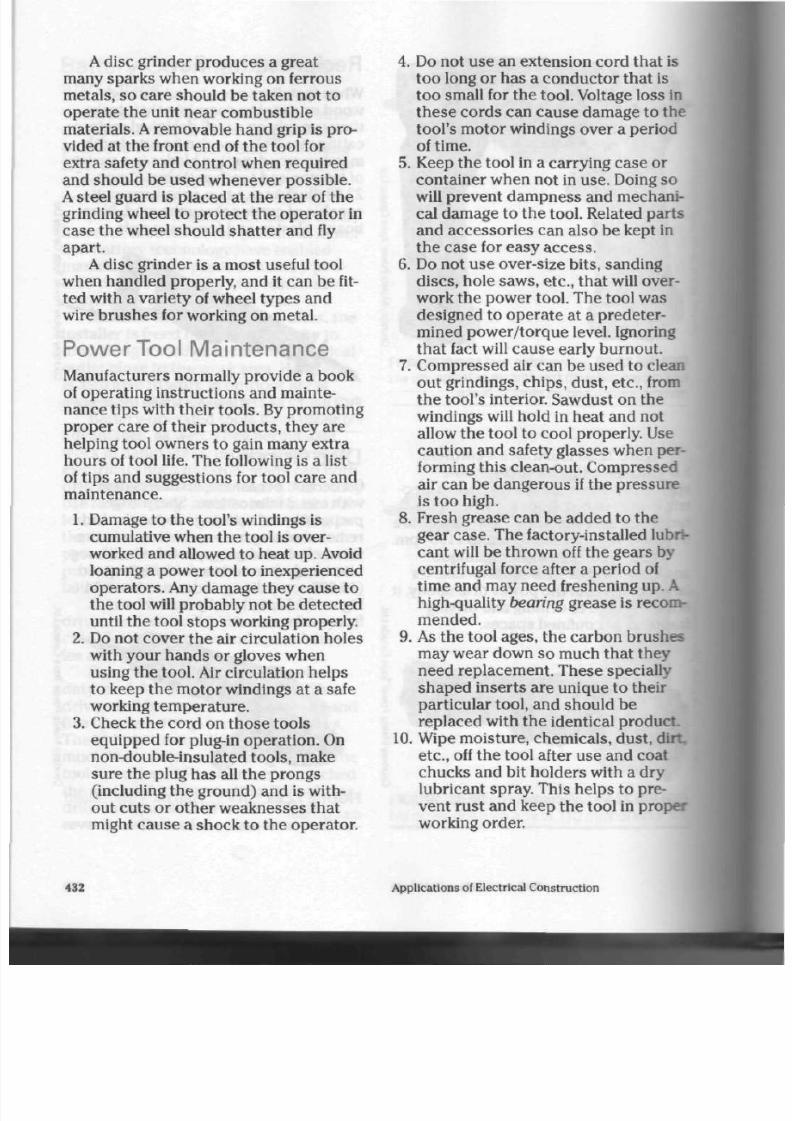
8/19/2019 Applications Electrical
http://slidepdf.com/reader/full/applications-electrical 437/447
A disc grinder produ ces a great
many spark s when working on ferrous
metals, so care should be taken not to
operate the unit near combustible
materials. A removable ha nd grip is pro
vided at the front end of the tool for
extra safety and co ntrol when required
and should be used whenever possible.
A
steel guard is placed a t the rea r of th e
grinding wheel to protect the o pera tor in
case the wheel should shatter and fly
apart.
A
disc grinder is a mo st useful to ol
when h and led properly, and it can b e fit
ted with a variety of wheel types and
wire brushes for working on metal.
Power Tool Maintenance
Manufacturers normally provide a book
of operating instructions and m ainte
nance tips w ith th eir too ls. By promoting
prope r care of their p rod ucts, they are
helping tool owners to gain many extra
hours of tool life. The following is a list
of tips and suggestions for tool care and
maintenance.
1.
Damage to the tool's windings is
cum ulative when the tool is over
worked and allowed to heat up. Avoid
loaning a pow er tool to inexperienced
ope rators . Any dam age they cause to
the tool will prob ably not b e de tecte d
until the
tool
stop s working properly.
2. Do not cov er th e air circulation holes
with your han ds or gloves when
using the tool. Air circulation helps
to keep the motor windings at a safe
working temperature.
3.
Check the cord on tho se tools
equip ped for plug-in op era tion . On
non-double-insulated tools, make
sure the plug has all the pro ngs
(including the gro und ) and is with
out cuts or other weaknesses that
might cause a shock to the operator.
4.
Do not use an extension cord that is
too long or has a cond ucto r tha t is
too small for the tool. Voltage loss in
these cords can cause damage to the
tool's moto r windings over a period
of tim e.
5.
Keep th e tool in a carrying ca se or
container when not in use. Doing so
will prevent dam pn ess and mechani
cal damage to th e tool. Related par ts
and a ccesso ries can also be kept in
the cas e for easy a ccess.
6. Do not u se over-size bits, san ding
disc s, hole saw s, etc., tha t will over
work the power too l. The tool was
designed to operate at a prede ter
mined power/torque level. Ignoring
that fact will cause early burnout.
7. Compressed air can be used to clean
out g rindings, chips, d ust, etc ., from
the tool's interior. Sawdust on the
windings will hold in heat and not
allow th e tool to cool properly. Use
caution and safety glasses when per
forming this clean-out. Compressed
air can be dangerou s if the pressu re
is to o high.
8. Fresh grease can be added to the
gear c ase . The factory-installed lubri
cant will be thrown off the gears by
centrifugal force after a period of
time and may need freshening up.
A
high-quality bearing grease is recom
mended.
9. As the tool ages, the ca rbon brush es
may wear dow n so much that they
need replacement. These specially
shaped inserts are unique to their
particular tool, and should be
replaced with the identical product.
10. Wipe moisture, chem icals, dust,
dirt
etc., off the tool after use and coat
chuck s and bit holders with a dry
lubricant spray. This helps to pre
vent ru st and keep the tool in proper
working order.
432
Applications of Electrical Construction

8/19/2019 Applications Electrical
http://slidepdf.com/reader/full/applications-electrical 438/447
C hoosing a P ower T ool
Th ere are som e major factors to con
sider w hen choo sing a too l. The follow
ing is a list of recommendations that can
help you to make the right choice .
1. Decide wha t typ e of job or proje cts
th e tool will be used for. Doing so will
allow you to cho ose a tool in the
power/torque range needed to per
form your task comfortably and with
out undue strain on the tool.
2. Try to m atch th e tool to th e size of
you r hand , arm stren gth, e tc. A large
high-torque tool in the hands of a
pe rson unable to con trol its weight
and pow er may re sult in a painful
accident.
3.
Look at several name brands and
compare their features, power, and
price before making you r pu rcha se.
Some manufacturers copy oth ers in
appearance and design, but leave out
key features which make a co nsider
ab le difference to the ea se of use on
th e job.
4. When co mp aring tools of various
makes and sizes, the nameplate cur
rent can b e a rule-of-thumb guide
line. Generally speaking, the higher
the cu rrent rating, the mo re powerful
the tool will be.
5. Check th e size of the chuc k on drills,
tool bit or blade holders, etc., as a
guideline to the quality of the tool.
Manufacturers seldom apply heavy-
duty, quality parts to a cheaper tool.
As a rule, you get wh at you pay for.
6. Remember that ball and roller bear
ings are far superio r to sleeve ty pe
bearings. They last much, m uch
longer.
7.
As a general
rule,
avoid "packag e
deals"
where many, low cost acc es
sorie s are include d w ith the too l. It is
often better to spend your money on
the tool alone and to add parts and
acc esso ry units when and if you
require them . Some name brand
manufacturers do, however, provide
special de als that are well wo rth
looking for. Top quality pa rts ne ed ed
for th e op eration of the tool may b e
included.
8. When choosing th e tool, inquire
about the warranty or guarantee that
is provided in writing by th e manu
facturer. Find out at the same time
wh ere repa irs can be m ade: not all
tool supp liers repair tools on the sel
ling pre m ises.
9. Look at th e length and natu re of cord
and the typ e of plug on power tools.
Rubber cords tend to be fairly flexi
ble in cold weather; in contrast,
plastic c ord s can be a bit stiff and
awkward to use o utdo ors in winter
months. Three prong plugs should
be on all metal tools tha t are not
double insulated and CSA approved
for the intended purpose.
10. Look carefully at battery-operated
tools for b atte ry voltage, cost of
spare batter ies and chargers, and
time required to recharge the bat
tery. Some tools require an overnight
charge, something that can be most
inconvenient on an imp ortant job
site project. Tools shown in this
chapter are designed to charge in
one hour, and can b e pa rtially
rech arge d in m inutes if only a few
m inute s of wo rk are required to fin
ish th e job.
Tools of the Electrical Trade
433
8/19/2019 Applications Electrical
http://slidepdf.com/reader/full/applications-electrical 439/447
F o r R e v i e w
1.
What two features make top qual
ity tools more desirable to the
installer?
2. W hen choo sing a screwdriver for
persona l use, what features should
be considered?
3. a) What p roc ess of repair is used
to reshape the tip of a worn, stand
ard slot screwdriver?
b) What care m ust be taken while
repairing the tip of the driver?
4. Name the thre e most comm only
used sizes of square-tip drivers.
State the screw sizes they are
designed to work with.
5.
What special treatm ent is given to
the long-shaft screwdrivers that
are used in and aroun d live electri
cal equipment?
6. Name two major ap plication s or
use s of side cutting p liers.
7. What special design feature deter
mines if a pa ir of pliers is high lev
erage or not? What is the advan
tage of high leverage pliers over
standard pliers?
8. What are the advan tages and
disadvantages of comfort-grips on
the han dles of various typ es of pli
ers?
9. State two specific uses of adjusta
ble pump pliers.
10. Why are slanted tong ue and
groove pump pliers the safest to
use?
11.
What special design features are
desirab le in a
metal-cutting
hack
saw?
12. List three types of hammers used
by the electrical trade and give an
application of each type.
13. Why must ca re be taken when
using steel measuring tapes near
live electrical circu its and equip
ment?
14. What protection do es the lockout
device illustrated in Figure 22.46
provide when persons from a num
ber of tra de s are servicing electri
cal equipment and their circuits?
15.
What special advantages doe s a
properly designed tool p ouch
have over a metal or wooden tool
box?
16.
What typ e of motor is used exten
sively in m odern pow er tools, and
why is that so?
17.
What is the advantage of speed
control on a power tool and how is
speed control achieved?
18. What design features indicate that
a power tool is of high quality and
suitable for industrial use?
19. Name two precau tions you can
take to reduce the chance of elec
tric shock when using power tools.
20 . What consideration should be
given to the user's physical size
when selecting a portable power
tool?
21. What safety equipment should be
worn by the op erator of a pow er
tool such as a hammer drill?
22.
List thre e major a dva ntage s of
cordless power tools.
23. What are the two most commonly
used voltages for cordless power
tools?
24 . Why is a motor-reverse switch
desirable on electric and battery-
operated drills?
25. Why is it useful for a cordless
pow er drill to have adjustable
torqu e settings?
434 Applications of Electrical Construction
8/19/2019 Applications Electrical
http://slidepdf.com/reader/full/applications-electrical 440/447
26. List three elec tric power too ls th at
are designed to e ase th e installa
tion of electrical equipment and
circuits.
27 .
What care must be taken with the
co rds and plugs of power-oper
ated tools?
28.
Why mu st power tools be cleaned
and blown free of wood dust and
othe r residue that h as accumu
lated on the inside?
29. What parts of a power tool require
lubrication from time to time, and
wh at lubricant is used for th e pur
pose?
30 . Which typ e of bearing is m ost
suited to long life in an industrial-
grad e pow er tool? Explain why.
Tools of the Electrical Trade

8/19/2019 Applications Electrical
http://slidepdf.com/reader/full/applications-electrical 441/447
Glossary of Electrical Terms
acceptable Equipm ent or installation
of equipment is accep table to th e
authority enforcing the Canadian Elec
trical Code.
accessible
Not perma nently closed in
by the structure or finish of a building;
can be remov ed without disturbing the
structure or finish of a building.
alive Co nnected to a sou rce of voltage,
or charg ed electrically to have a volt
age different from that of the earth.
alternating current (AC) A current
which reverses its direction and magni
tud e in a period ic man ner, rising from
zero to a maximum value in one direc
tion, falling to zero, and reversing in the
opp osite d irection to a maximum value
before falling again to ze ro.
ampacity
The current-carrying capac
ity of cond ucto rs ex pressed in
amperes.
amperes
(A) The com mon ly used unit
of electrical current flow in a circuit.
AWG
Am erican Wire Gauge, used to
measure solid, non-ferrous (usually
copp er or aluminum) conductors, pro
viding both gauge number and diame
ter in tho usa nd ths of an inch.
branch circuit
That pa rt of a circuit
which extends beyond the final over-
current device protecting the circuit or
system.
CEMA Can adian Electrical Manufactur
ers '
Association, which regulates sizes,
dim ensio ns, and configurations of elec
trical devices and equipm ent.
CMA Circular mil area, which indica tes
the nominal size of conductors larger
than
No.
0000 AWG.
Canadian Stand ards Ass ociation (CSA)
The association that approves and
tests electrical devices and equipm ent
to be sold and installed in Canad a.
cycles
Cycles per second, or the num
ber of pulsations occurring in an alter
nating cu rrent system w ithin one sec
ond. Consists of one positive and one
negative maximum va lue in an alternat
ing cu rrent.
direct cu rrent (DC) An electric curren t
that flows in one direction only and is
reasonably free from pulsations.
Obtained in a pulsation-free form from
a battery, it can also be produced by a
generator or obtained electronically if
alternating current is passe d through a
rectifier.
hertz (Hz)
The mea surem ent of alter
nating curre nt frequency indicating th e
num ber of cycles per seco nd.
identified
a. A white or natural grey
covering on a conductor, b. A raised
ridge on the surface insulation of some
wiring co rds , c. A silver-coloured ter
minal screw on wiring devices.
IEC
International Electro-technical
Commission. The European equivalent
to CEMA and NEMA.
436
Applications of Electrical Construction
8/19/2019 Applications Electrical
http://slidepdf.com/reader/full/applications-electrical 442/447
kilowatt (kW)
A unit of power measure
ment to 1000 W.
kilovolt (kV) A unit of electric al pre s
sure equivalent to 1000 V.
line
A
term usually referring to the
input side of a switch, m eter, or co ntrol
ling device for a motor.
load
A
term usually referring to the
ou tpu t sid e of a switch , meter, or con
trolling device for a motor.
NEMA National Electrical Manufactur
ers '
Asso ciation. Th e American organi
zation that con trols the dim ensions,
sizes,
and configurations of electrical
devices and equipment.
neutral The con duc tor that divides the
secondary of a supply transformer
into two equal sections, providing two
voltages from three wires in the system.
It is norm ally wh ite or grey in co lour.
outlet
A point in th e circuit at which
current can be taken to supp ly electri
cal devices or equipment designed to
operate on that circuit.
overcurrent device
A fuse o r circuit
breaker designed to open a circuit auto
matically under predeterm ined over
load or short-circuit conditions.
overload
A
flow of cur ren t in excess of
normal, predetermined circuit capacity,
which can cause overheating or dam
age to the circuit.
primary The input side of a transfo rme r
into which voltage is placed so tha t it
may be raised o r lowered in value.
PVC
Polyvinylchloride. A plastic
material used in the manufacture of
electrical cond uit and fittings.
receptacle One or mo re female con tact
devices on a comm on moun ting
brack et for the con nection of plug-in
equipment.
resistance
The prop erty of a cond uc
tor or electrical device that o pp ose s
the flow of current through the system.
Measured in ohms.
secondary
The ou tpu t section or wind
ing of a transformer from which voltage
is taken after it has been raised or low
ered in value.
short circuit
A
circuit fault caused by
contact between two opposite sections
of an electrical circuit. An ab norm ally
low-resistance path is created, resulting
in sudden and possibly dangerous high
currents.
Underwriters' Laboratories UL) The
American equivalent to the Canadian
Standards Association. The organiza
tion test s and appro ves electrical
devices and equipment for use in the
United S tates.
voltage
(V) A unit of electrical pressure
applied t o a circuit.
wattage W)
A
unit of electrical energy
or power resulting from electrical pres
sure forcing a current throug h the
circuit.
For Reference
Canadian Electrical C ode, Part 1,
Canadian Standards Association.
Heating and Cooling Load Calculation,
Ontario Electrical League.
Intermediate Electricity, Frank J. Long,
General Pub lishing.
In troductory Electricity, Frank
J.
Long,
General Pub lishing.
Lucalox High Pressure Sodium Lamps,
8707-3,
GE Lighting.
Multi-Vapour SP30 Metal H alide Lamps,
206-81245 (4/88), GE Lighting.
Typical W iring Diagrams,
publication
Gl-2.0, A llen-Bradley.
Glossary of Electrical Terms
437

8/19/2019 Applications Electrical
http://slidepdf.com/reader/full/applications-electrical 443/447
Index
Adap ters for Iampho lders, 29,
308-9
Ambient temp erature , 249
Am erican W ire Gauge (AWG),
53-54
Am pacity, 60-62
Amperage
in Oh m's Law, 9-10
rating for switches, 15
Annealing, of conductors, 53 , 250
Antioxidant chemicals, 49
Appliance
cord s ets, 67
large, 2
small, 2
Arcing, 15-16,335,346
Area of cros s-section , 54-55
B
Baseboard heater
installation, 277
overheating protection,
297,
298
type s, 277, 279
C
Cable
accessories, 99,141
acce ss to , 90
aluminum-sheathed,
140-48
applications, 139-40,148,
153,155-57,160-61
architectural symbols,
93-98
armoured, 136-41
connector, 144-45
construction, 88,136-37,
151,156
fastening to bo x, 90-91
fireproof, 151-55
fishing, 139
in concealed installations,
91-92
installation, 90,142
insulation, 88,136,151
materials,
88,136-37,151
mineral-insulated, 151-61
multi-conductor, 141-42
nonmetallic sheathed, 88-92
pliers, 99
ratings, 136,141
residential a pplications, 92
ripper, 99
single-conductor, 141,160
sizes,
88,151-54
supports, 90,138-39,147
terminating, 111,
137-38,
143, 146-47,157-59
trade names, 88,136
underground, 91,137
water-tight, 139-40,149
wiring diagram sym bols,
92,
94-98
Canadian Building Code, 153,
268-70
Canadian Electrical Code,
28-29,31-32,33,39,42,55,
65,70,71,75,84,85,88,90,
91,102,141,147,162-63,171,
174,184,188,193,199,206,
211-12,224,240,246,250,
253,
259,
306,335,
337, 346
Canadian Standards
Asso ciation (CSA),
15,37-38,
68,102,263,356,394,396,
402,433
Circuit breaker
advantages of,
241-42
disadvantages of, 42
for m oto rs, 346
GFI ty pe , 242-47
thermal overload relay,
337-43
Circular mil area , 54
Cold
flow of co ndu ctors , 49,250
lead of condu ctors , 280
Conductor
aluminum, 48-49
cable, 51,53
compound, 53,143
copper, 48, 249
cord, 52-53
forms, 49-53
heat generation factors,
249-50
installation in a lug, 55,
107-8
installation in conduit,
188-92
Insulation,
55,58-60,249
ma terials, 48-49
overheating, 84,248
single strand , 49,141
sizes,
53-55,88,238,240
steel, 49
wire, 49-50, 53
Conduit
applications and features
162,170-71,178-80,
182-83
bending hydraulically.
168-69,172, 179
ben ding man ually, 165-66.
168,172, 179
bending with heat, 180-82
condulets, 173-77,211
cutting, 184
EMT
(thin wa ll), 170-73
expan sion joints, 180
fishing, 189,192
fittings, 171,174-77
grounding, 184
installation, 179
liquid-tight flexible, 185
metallic flexible, 180,183
nonmetallic flexible, 183-84
number of conductors
allowed, 193
PVC-jacketed, 171
rigid aluminum, 163,178-3
rigid
PVC,
179-80
rigid (thickw all), 16369
secu ring to fish tap e, 191
sizes,
162-63,182, 238,
24f
supports, 163,183,184
termination, 177-78,
180.
185
threading, 164-65,179
types, 163-73,178-80, IS
types of bends, 166-67
Connector (solderless)
applications, 105
com pression, 104,106.
108-9,112
heat-shrink tubing, 119-22
insulating materials,
112.
114-19
materials, 102,108
mechanical, 107-8,169
resin-splicing kits,
115-
set-screw, 104-5
438
Applications of Electrical Construction

8/19/2019 Applications Electrical
http://slidepdf.com/reader/full/applications-electrical 444/447
splice tape, 112-14,119
tools,
109-10,112
twist-on, 102-3
types, 102-8
water-tight, 140
Cord fittings
dead-front plug caps, 65-66
heavy-duty cap s, 64
removable, 67
Crimping and co mpre ssion
tool, 157-58
Current
alterna ting (AC), 15
direct (DC), 15
eddy, 142
sheath, 14M2,160
Cycle (see Frequency)
Design tem peratu re, 286
Dies
for condu ctors, 49
for con dui t, 164-65
Discharge light sources (see
Fluorescent lamp)
Drilling d evice s
hammer-driven, 391
power-driven, 391-92
Drivers and drills
battery-operated.
430-31
electric, 391,425-29
hand tools, 407-11
hex key, 410
hollow-shaft
nutdrtver,
410-11
multi-purpose
screwdriver.
409-10
Phillips scre wdrive r. 409
powe r tools , 425-31
slot screw driver, 407-9
square-tip screwdriver
409
Torx screwdriver, 409
Electrical and Electronic
Manufacturers' Association
of Canada (EEMAC). 345.3
Electric shock, 6-8.43.68
217,
234, 244-45
Electrolysis, of cond ucto rs, 46
F
Fastener
drilling devices, 391-92
hollow-wall, 392-93
masonry, 387-91
powder-actuated.
394-403
screw, 376-87
Fire endu rance test, 152-53.155
Flat-rate, hot-water heater. 3,
206, 209
Fluorescent lamp
advantages,
301-2,305
applications, 315,322-23,
327-28
ballast,
304,306
disadvantag es, 302
efficiency, 331-32
high-intensity discharge,
310,312-28
high-pressure sodium,
323-28
instant-start, 306, 308
low w attag e biaxial,
308-10
Lucalox, 317, 325-26
maintenanc e, 332
m ercu ry vapou r, 312-16
metal
ha lide, 318-23
metric sizes, 308
multi-vapou r, 328-29
ope ration , 304-5
pow er groove, 310-12
rapid -start, 305-7
starting, 302,304
tube life, 301-2
tube parts, 302-3
tungsten-halogen, 329-31
Frequency, 2
Fuse
arc-quenching m aterial,
257-59,262
circuit fault indications,
255-56
coding. 254-55
design. 250-54, 256-59,
261-62
dual-element, 261-62
ferrule-contact c artridge,
256-57
for
motors. 263,346
high-mpture capacity,
259-61
knife-blade cartridge,
257-58
M effect. 250-51
I fatigue. 258
; delay. 252.254
,258
sot 5,250-51
,
6,253-54.
256-58,
MM2
renewable-link cartridge,
258
screw -base (plug), 252,
254-55
short circuits,
5-6,250-51
sizes, 256
spiking, 258
time-delay, 251-57, 260-64
tripping level, 42
Ganging outlet boxe s, 75
Gauge, for wire and c able, 53,
55
Ground fault interrupter (GFT
features of, 43-44, 247
functions of, 42, 242
operation of, 245-47
testing of, 43,247-48
Grounding
of neutral wire, 6-8
why needed, 6-3
H
Hand tools
cuttin g, 415-17
drivers, 407-11
measuring, 418-19
plie rs, 411-15
pouches and kits, 421
striking, 417-18
High tension lines, 3
Hysteresis loss, 346
I
Industrial power supply
circuit brea kers, 241-42
conductor and conduit
size, 238, 240
dem and factor, 241
550 V and 440 V, 230-32
grounding, 234,238
metering, 233-34,24041
motor-driven, 229
120 V/208V, 230, 235-38
polypha se, 229
600 V/347V system , 231
sub-disconnect switches
233
Insulation
attic, 273,
276-77
batts,
269-70, 273
function of, 267
poured, 269,271-73
rigid, 271-72, 274
rolls, 269,271,273
4 3 9
8/19/2019 Applications Electrical
http://slidepdf.com/reader/full/applications-electrical 445/447
RSI values , 268-74
vapour retarders, 272-76
Interlocking, 357-58, 360
K
Kirchhoff's Current Law, 245
Knockout
cutters, 186-87
for co ndu it, 177
in outlet boxes,
71,82
Lampholder
adapte rs, 29
candelabra, 29
circuits, 31
construction, 29
insulating link, 31
interme diate, 29
location, 31-32
medium, 28-30
miniature , 29
mogul, 28
scre w-b ase s izes, 28-29
switch mechanisms, 30
Lighting-load c alculation s, 16
Line
side,
3
term inals , 3, 20, 22, 212
Lineworkers, 411,415,419
Load, side of sw itch, 5
Locked rotor curre nt, 334,361
Loop system , 90
M
Main disconnec t switch
fuses in, 5-6
loca tion of, 3, 200
Masonry fastener
drive-in a ncho r, 391
expansion shield, 388
lead sleeve anchor, 389-91
scre w an chor, 387-88
self-drilling s hield, 388
Meter,
3,199,214,221,224-26,
233,
239, 240-41
Motor control
auto transformer starter,
364-66
conductor sizes, 335,337
direct-cu rrent, 371-74
jogging circuits , 354-56
location, 335
magnetic, 344-45,346-47,
349-50
maintain contacts, 350-51
man ual, 344
multi-speed, 360-63
need,334
overcurrent protection,
335
primary resistor starter,
361,364
reduced voltage control,
356-57
reduced voltage starters,
361-66
reversing, 357-59,370
single-phase, 370
solid-state starte r, 370-71
stat ions , 351-53
switche s, 335
thermal overload relay,
337-43
Wye-Delta starter, 367-69
Muscu lar freeze, 42
N
National E lectrical
Manu facturers' Association
(NEMA),41,260,345,347
Ohm's Law, 9-10
Outlet box
cable clamp s, 82-83
concrete-masonry-tile, 82
conductor capacity, 84-86
ganging, 76-77
grounding, 84
materials, 70, 75-76,80
octag on, 70-72
pan cak e, 72-73
sectional
plaster,
74-79
squ are , 72-74
steel stud, 77, 79
utility, 80-81
vapour barrie rs, 81
Oven
continuous clean, 131
heat control, 130-31
pyro lytic , 131-34
rotisserle, 134
self-cleaning, 131-34
timer, 132
Overload relay selection chart,
343
Oxidation
of cond uctors, 48,108,250
of fluorescent tubes, 305
Parallel circuit, resistanc e of.
9-10
Plaster ears
for receptacles, 41-42
removing, 42
Pliers
cable cutters, 413-14
diagonal cutting, 412-13
high-leverage,
411-13
long-nose, 414
pum p, 414-15
side cutting, 411-12
Plug cap
connection, 65
dead-front, 65-66
electrical ratings, 68
female, 64
for appliances, 67
grounding, 68
heavy-duty, 64
male, 64
twist-lock, 68
Powder-actuated fastener
high-velocity tool, 401
in concrete, 397-99
in maso nry and sU
399-401
low-velocity tool, 394-95
powder-charge cartric
396
safety equipm ent, 402-3
safety recommendatio
403-4
typ es, 396-97
Power
factor, 305
ratings for switches. 1
Power tool motor
bearing s, 425
parts,
423
r p m , 424-25
torqu e and speed, 423
Power tools
battery-operated drrwi
and drills, 430-31
choosing, 433
disc grinder, 431-32
electric drills , 425-29
holster-style pouches.
421-22
ma intenance, 432
motor, 423-25
quality and cost, 422-23
reciprocating saw,
431
Pry-outs, in outlet boxes. 5J4
440
Applications of Electrical Construction

8/19/2019 Applications Electrical
http://slidepdf.com/reader/full/applications-electrical 446/447
R
Receptacle
combinations, 34
construction, 33
covers, 45
crow's foot, 35
direct curren t, 36
duplex, 39
electric shaver, 43
ground fault interrupter,
42-44
grou nding , 38-39
hospital grade grounding,
44-45
installation regulations, 33
locking, 38
NEMA, 41
non-locking, 37
polarize d, 41
range and drier, 36
rang es of, 33
replacement, 40
sh ap es , 34-36
split , 39-40
standardized, 41
tandem , 36
twist-lock, 35
two-prong, 34
U-ground, 34-35
Residential electric heating
adva ntage s of, 266
baseboards, 277-79
base m ent, 283-84
central heating, 266
costs of, 267, 294-95,297
end rate, 267
forced air units, 294-96
heater location, 292
inspections, 267, 274
insulation, 267-72
radiant-heating cable, 277,
279-80, 297-99
radiant-heating foil, 279-81
selecting size, 291-92
thermostat location, 292-94
unitary, 266-67
ventilating dev ices, 274,
276-77
Residential heat loss
basements, 283-84
calculations, 266, 284-86,
290-91
conc rete slab, 282
degree days and design
tem pera ture, 286-89
do ors and window s, 286, 290
fireplaces, 281-82
infiltration, 286, 290
pipes and electrical
box es, 281-82
walls and ceilings,
284,
286
windows, 280-81
Residential power supply
combination units, 202-4,
214
conductors, 199
flat-rate syst em s, 206, 209
grounding, 215, 217-18,
223-24
inspection permit, 226
installation, 203
me ter cabinet, 215
meter socket, 206,208-10
overhead, 3,199,200, 201
service, 199
service boxes, 214
service box installation, 212
service
ell,
211-12
service entrance elbows,
210-11
service mast, 206-7
size and capacity, 199,202-3
tem pora ry service, 226-27
unbalanced system, 8-9
underground,
3,199,
210,
212-13
Resistance
for co nduc tors, 61
in Ohm 's Law, 10
Root Mean Square (RMS), 251
S
Schematic wiring diagram
symbols, 348, 350
Screw fastener
Allen, 378
bolt s treng th, 386-87
cam-out, 377
construction materials,
385-86
driving configuration, 377,
379
dua l-drive, 378-79
head design, 376
hexagon,378
length and diameter, 384-85
m achin e, 379-81
neck/shoulder,
378-79
Phil lips, 377-78
point designs, 385
Robe rtson, 377
self-tapping, 382-83
shank and body, 378-79
slotted, 377
squ are recess, 377
thre ad typ es, 379-84
Torx, 378
woo d, 382-84
Series c ircuit, resis tanc e in,
Series/parallel, switch
combinations, 124-34
Service m ast
as ground, 7
installation, 204,206
requireme nts, 204
Sheath cur rents, 160
Single-phase voltage, 2
Society of Autom otive
Eng ineers (SAE), 386-87
Spiking, 258
Switch (heat control)
five heat, 124
for ovens, 130-31
infinite-heat, 128-30
seven-heat, 126-28
three-heat, double pole
124, 126
three-heat, single-pole,
124-25
Switch (light)
alternate , 25
and re ceptacle unit, 46
applications, 17
consecutive, 25
dimmer, 16, 25-26
double-pole, 17, 19
electrolier, 22-25
flush, 12
four-way, 18, 21
function of, 13
internal construction, 1
non-indicating, 21
operating m echanism, 1
30
rat ing s, 14-16
single-pole, 17-18
surface, 12
test equipm ent, 16
three-way, 18,20-21
trillte , 22-23
wiring symb ols, 17
Stroboscope effect, 302
Supply authority, 199, 203
T
Tables
air change s per hour, 29
allowable ampacities fo
Index
44
8/19/2019 Applications Electrical
http://slidepdf.com/reader/full/applications-electrical 447/447
aluminum c ondu ctors, 62
allowable ampacities for
copper c ondu ctors, 61
batt insulation RSI value
data, 270
Canadian Building Code's
minimum insulation
requirements, 268
cartridge power loads,
396
common coarse and fine
thread screw sizes, 380
cost to illuminate for a
year, 332
cross-sectional a reas of
cond uit, 197
degree days and design
tem per ature s, 287-89
determining motor
conductor sizes, 338
dimen sions of bare
copp er and aluminum
stranded conductors, 57
dimen sions of insulated
cond uctors for
calculating cond uit fill,
196
dimen sions of insulated
copper and aluminum
cond uctors, 56
dimensions, weights, and
resistance of bare
copp er wire, solid, 58
dimensions, weights, and
resistance of bare
copp er wire, stranded, 59
distan ces for fasteners, 399
electrical sy mbo ls for
light sources and power
consumption, 331
low and standard watt
density heater
specifications, 293
markings and mechanical
properties of hex cap
screws, 386
maximum allowable p er
cent conduit fill, 197
maximum num ber of
cond uctors (imperial),
195
maximum n um ber of
conductors (metric), 194
metallic flexible c ond uit, 183
minimum RSI values for
various assem blies in a
building, 270
minimum size of
grounding
conductor.
231
number of conduc tors in
boxes,
85
overcurrent devices, 337
overcurrent protection,
336
resistance v alues for
building materials, 285
roll insulation RSI data,
271
RSI values for insulating
materials, 269
sizes and ratings of
magnetic motor
starters , 347
spac e for conduc tors in
boxes, 84
Three-wire system, for two
voltages, 2,4,229 , 231
Tools
battery-operated drivers
and drills, 430-31
cutting,
415-17
disc grinder, 431-32
driver family of hand
tools , 407-11
electric drills, 425-29
measuring, 418-19
plier family of hand too ls.
411-15
portable power, 422-33
po uc hes and kits, 421-22
quality, 406,
421,
422-23
reciprocating saw, 431
safety eq uipm ent. 419-20
strikin g, 417-18
Transformer
contacts, 365
current-reducing, 215.
234, 236
distribution, £4,212
step-down, 4,235,345
T rating, for incandescent
lamps, 15
Trilite, 22-24
Tubing (heat-shrink), 119-22
Tungsten-halogen lamp,
32939
U
U factor, 286
Underwriters' Laboratories
(UL),
15
V
Vapour barrie rs, 77-78,272-76