application of new technologies for power transmission systems · application of new technologies...
TRANSCRIPT
Application of New Technologies for Power Transmission SystemsPower Transmission and Distribution
IEEE SFO PES CHAPTER7th June 2006, SFO CA
Mark Reynolds P.E.Ph: (503) 638-0134
Cell: (503) 887-0925

Page 2 May 06 Power Transmission and DistributionPTD HVS
Our Vision

Page 3 May 06 Power Transmission and DistributionPTD HVS
At a glance – FY 2005

Page 4 May 06 Power Transmission and DistributionPTD HVS
Pressures on Transmission Development
Page 5 May 06 Power Transmission and DistributionPTD HVS
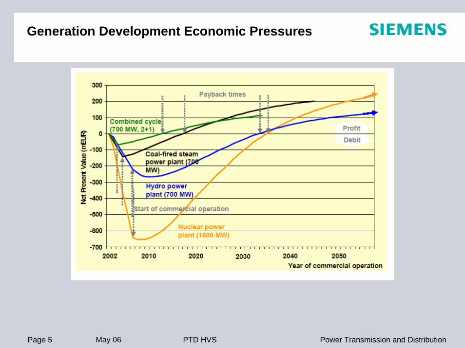
Generation Development Economic Pressures

Page 6 May 06 Power Transmission and DistributionPTD HVS
230kV
Crockett
Contra Costa PP
500kV
230kV
500kV
230kV
Tesla
San Jose
Newark
Concord
Pittsburg PPPotrero
Hunters Pt.
M etcalf
The Geysers
Oakland
Vaca - Dixon
M oss Landing
PP
Ravenswood
To Sobrante
ToM oraga
ToHetch
Hetchy
To M organHill Junction
Green Valley
500kV
San M ateo
M artin

Page 7 May 06 Power Transmission and DistributionPTD HVS
PTD-DivisionHigh Voltage Systems
Page 8 May 06 Power Transmission and DistributionPTD HVS
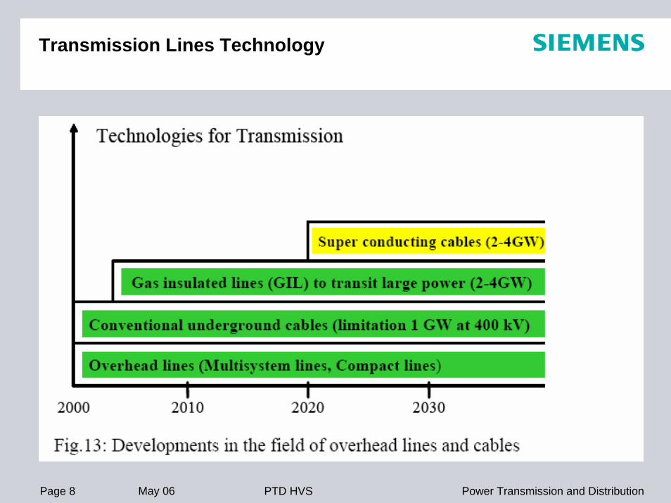
Transmission Lines Technology

Page 9 May 06 Power Transmission and DistributionPTD HVS
ADVANCES IN POWER ELECTRONICS

Page 10 May 06 Power Transmission and DistributionPTD HVS

Page 11 May 06 Power Transmission and DistributionPTD HVS
Superconductivity Applications

Page 12 May 06 Power Transmission and DistributionPTD HVS
Summary - The Spectrum of System Dynamics
Very fast transients
Transients &System interactions
Subsynchronousresonances
Poweroscillations
Switching voltage (disconnector etc.)Lightning overvoltages
Power converterFerro-resonanceTransformator switchingGrid resonances
Power Station - Line - Load
Oscillation of turbine generator multi-mass systems: above approx. 300 MW(at thermic und nuclear power plants,i. e. only at „long shaft systems“)
Rotor oscillations of generators
40 MHz
10 MHz
5 kHz1 kHz
100 Hz
10 Hz
5 Hz
50 HzfNPower generationand transmission
10 kHz
CLC
&
Prot
ectio
n
0 Hz

Page 13 May 06 Power Transmission and DistributionPTD HVS
Development of Power Electronic Componentsfor Adjustable Speed Drives
100
10
1
0.1
0.01100
1000
10 000
10100 10 0001000
Trend
Blo
ckin
gV
olta
ge(V
)
Switchin
g frequ
ency
in co
nvert
ers(kH
z)
Power-MOS
10 kW
LV-IGBT
1 MW
HV-IGBT
4 MW
GTOIGCT
7 MW
15 MW
40 MW
Trend
Turn-off current (A)
typica
l
Power rating
Thyristor
Semiconductor Trends will be driven primarily by TractionConverters due to large number of Applications and Devices

Page 14 May 06 Power Transmission and DistributionPTD HVS
FACTS Controllers TodayImpact on System Network Performance
Oscillation Damping(Meshed System)
OscillationDamping(Transmission System)
Transient Stability(Bulk Power System)
Load Flow Control(Meshed System)
Voltage Quality
HVDCUPFCPSTTCSC
CSC
SVC/GSTATCOMFSC
low or no influencesmall influencemedium influencestrong influence
FSC Fixed Series CompensationSVC/SVG Static Var Compensator / GeneratorTCSC Thyristor Controlled Series CompensationPST Phase Shifting TransformerUPFC Unified Power Flow ControllerSTATCOM Static Synchronous Compensator

Page 15 May 06 Power Transmission and DistributionPTD HVS
System Transients - The Spectrum
Computer Simulation On-Site Measurements
Real-Time Simulation
SubsynchronousResonances
PowerOscillations
10 Hz
`60 Hz 60 Hz UnbalancesPower Oscillations
SubsynchronousResonances
1 kHz
5 kHz
10 kHzPower
Electronics
Controland
Protection
40 kHz
10 MHz
40 MHz
Harmonics
Fast Transients(VF Transients)
0 Hz 0 Hz
Grid
50 Hz
Machine GridFrequency Transformation
Page 16 May 06 Power Transmission and DistributionPTD HVS
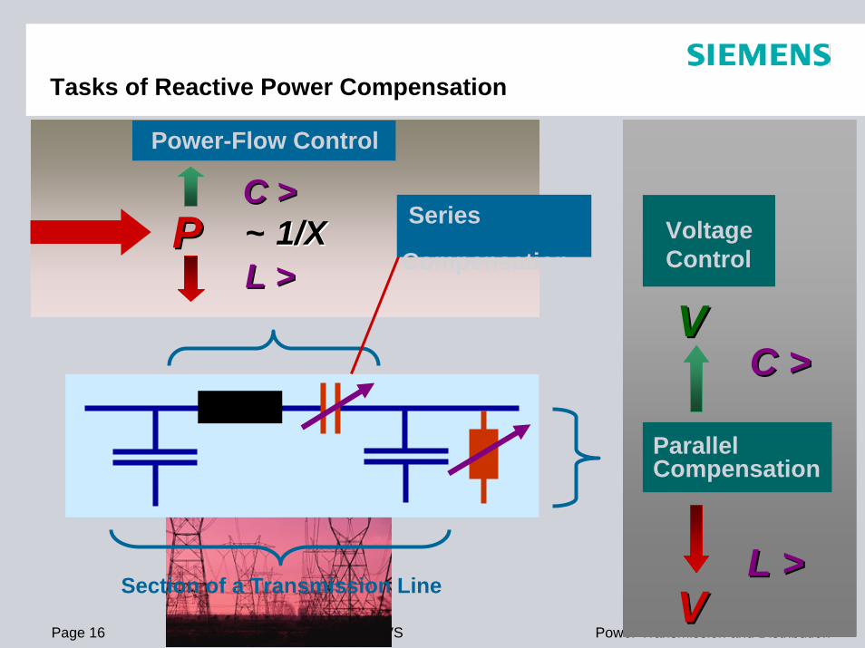
Power-Flow Control
P P Voltage Control
Parallel Compensation
Tasks of Reactive Power Compensation
Section of a Transmission Line
C >C >VV
VV
Series
Compensation
C >C >
L L >>~ 1/X1/X
L L >>

Page 17 May 06 Power Transmission and DistributionPTD HVS
FACTS Applications in Power SystemsRadial SystemRadial System -- Improvement of Power Quality:Improvement of Power Quality:
~ SVC• Voltage Control• Power Oscillation Damping
TCSC• Load Flow Control• Power Oscillation Damping• SSR Mitigation
~ ~
~
FSC / TPSC• Increase of Transmission
Capacity
~~ ~GPFC• Load Flow Control• Power Oscillation
Damping
Meshed SystemMeshed System -- Power Flow Control:Power Flow Control:
Option:Option:
Option for Combinations

Page 18 May 06 Power Transmission and DistributionPTD HVS
TPSC (Thyristor Protected Series Capacitor)
1 series capacitor
2 thyristor valveas fast bypass - device
3 current limiting reactor
4 MOV
5 bypass circuit breaker
6 bypass damping reactor
7 platform disconnectswith grounding switch
8 bypass disconnectPLATFORM
87 7
1
4
32
6
5

Page 19 May 06 Power Transmission and DistributionPTD HVS
Advanced Power Transmission SolutionsLight Triggered Thyristor Valves

Page 20 May 06 Power Transmission and DistributionPTD HVS
Shunt Compensation by SVCTechnical Main Features
Direct Light Triggered Thyristor:- Reduced Valve Components- No auxiliary Energy or logic Circuits at High Potential
- Better di/dt Capability- Integrating the break-over Protection against Overvoltage
2 Years or more period forMaintenance requiring shut-off
System Reliability 99% or betterdue to redundant Componentsand proven Technology.Standard SVC Valve Module
Use of Siemens Standard Industrial Controller Hardware Simatic TDC for Valve Control and Protection Function ensures long-term Availability of Spare Part Supply

Page 21 May 06 Power Transmission and DistributionPTD HVS
FACTS - Application of Series Compensation
Increase of Transmission Capacity
TCSC/TPSCTCSC/TPSC FSCFSCα
~ ~
Damping of Power OscillationsLoadflow ControlMitigation of SSR
Fixed Series Compensation:
Controlled Series Compensation:

Page 22 May 06 Power Transmission and DistributionPTD HVS
TPSC - Thyristor Protected Series Compensation
Vincent/USA

Page 23 May 06 Power Transmission and DistributionPTD HVS
Benefits of TPSC: High Availability after Fault Clearing -Standard FSC with Arresters needs up to 8 h to cool down
auto-reclosure
212°C
50°C
TPSCvalvetemp.
60 s after the 1st fault thevalve temperature rise is 2.2 K
thyr. valvebypass CB
linebreaker
5 cycles fault clearing time

Page 24 May 06 Power Transmission and DistributionPTD HVS
Thyristor-Controlled Series Capacitor (TCSC)Kayenta Substation, USA

Page 25 May 06 Power Transmission and DistributionPTD HVS
TCSC - The Impedance Curve
Impedance = Capacitor Voltage / Line CurrentImpedance = Capacitor Voltage / Line Current
„High Impedance Sensitivity“ Area
impedance as function of firing angle
-13,27
0
13,27
26,54
39,81
90 100 110 120 130 140 150 160 170 180
alfa
impe
danc
e / O
hm
Xtcsc
„Low Impedance Sensitivity“ Area
Active Damping by means of α ?

Page 26 May 06 Power Transmission and DistributionPTD HVS
TPSC versus TCSC - Benefits for active Dampingimpedance as function of firing angle
0
1
2
3
90 100 110 120 130 140 150 160 170 180
alfa
impe
danc
e / O
hm
L = 2.1 mH (TPSC)L = 12 mH (TCSC)
TPSC: “Increased Sensitivity”
TCSC: “Low Sensitivity”

Page 27 May 06 Power Transmission and DistributionPTD HVS
Poste Montagnais 476Mvar FSC @ 735kV, Canada
Page 28 May 06 Power Transmission and DistributionPTD HVS
Sera de Mesa 107Mvar TCSC @ 500kV, Brazil

Page 29 May 06 Power Transmission and DistributionPTD HVS
Vincent 401Mvar TPSC @ 500kV, USA

Page 30 May 06 Power Transmission and DistributionPTD HVS
Var TechnologyShunt compensation
MSC / MSR
~
52 < kV < 100050 < Mvar < 500
Mechanical SwitchedCapacitors / Reactors
Reactors
Switchgear
Capacitors
SVC
~
52 < kV < 100050 < Mvar < 800
Static VarCompensator
Reactors
Thyristor Valve(s)
Control & Protection
Transformer
Capacitors
STATCOM
52 < kV < 100050 < Mvar < 800
StaticCompensator
GTO/IGBT Valves
Control & Protection
Transformer
DC Capacitors
~

Page 31 May 06 Power Transmission and DistributionPTD HVS
Static Var Compensator (SVC)Typical SVC Configuration
LV bus bar
Fixed filter circuit
Thyristor controlledreactor
Thyristor switchedcapacitor
Control
Step-down transformer
HV
LV

Page 32 May 06 Power Transmission and DistributionPTD HVS
Static Var Compensator (SVC)Common Configurations
TCR, FC TSR, TSCTCR, TSC, FC

Page 33 May 06 Power Transmission and DistributionPTD HVS
Shunt Compensation by SVCFunil SVC, Brazil, Container Building - 3-D-View
Advantages:- Reduced Installation Time- Relocatable- Pre-Tested in Factory,
Reduced Commissioning

Page 34 May 06 Power Transmission and DistributionPTD HVS
Shunt CompensationStatcom versus SVC - Basic differences - Summary
Issue Statcom SVC V/I characteristic good undervoltage performance
Current source good overvoltage performance Impedance
Control range Symmetrical otherwise Hybrid solutions
freely adjustable to any range by TCR/TSR /TSC branches
Modularity Same converter usable for various applications (STATCOM, UPFC, CSC, B2B etc) Redundancy no degraded mode
TCR/TSR/TSC branches used in SVC and TCSC/TPSC Redundancy Degraded mode operation
Response time 1 to 2 cycle 2 to 3 cycle Transient behaviour Self protecting at critical system
faults Available before, during and after critical system conditions
Space requirements 40 to 50 % 100 % Availabilty 96 to 98 % > 99 % Investment costs 120 to 150 % 100 %
Page 35 May 06 Power Transmission and DistributionPTD HVS
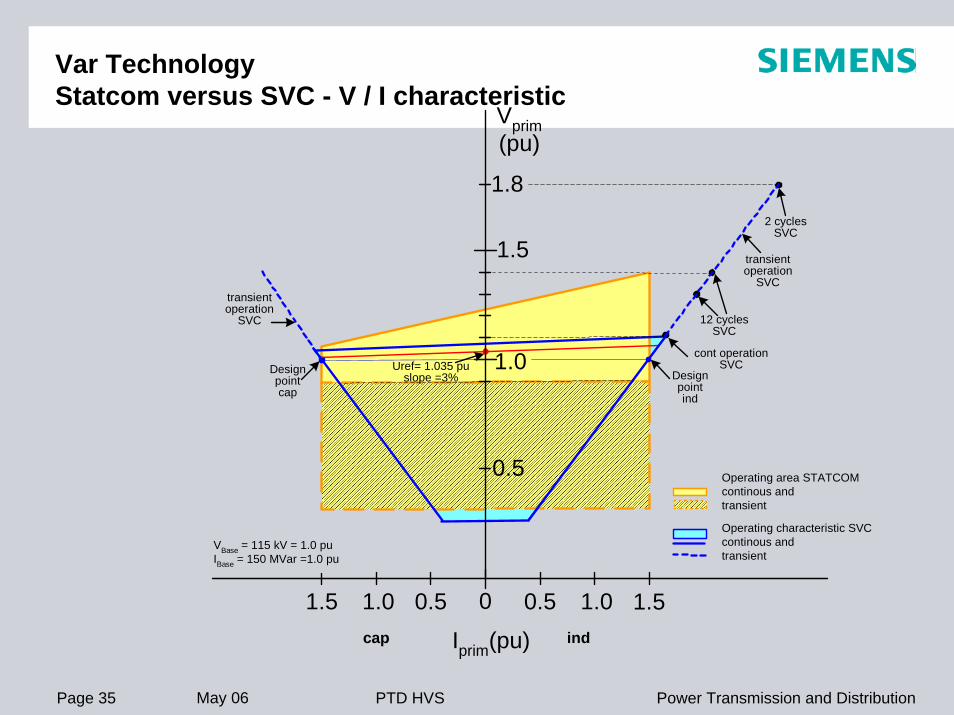
Var TechnologyStatcom versus SVC - V / I characteristic
Vprim(pu)
1.5
1.8
1.0
0.5
0 0.5 1.0 1.51.5 1.0 0.5
Uref= 1.035 puslope =3%
12 cyclesSVC
Designpointind
Designpointcap
2 cyclesSVC
Operating area STATCOMcontinous andtransient
Operating characteristic SVCcontinous andtransient
cap ind
cont operationSVC
VBase = 115 kV = 1.0 puIBase = 150 MVar =1.0 pu
transientoperation
SVCtransientoperation
SVC
Iprim(pu)
Page 36 May 06 Power Transmission and DistributionPTD HVS
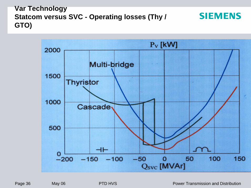
Var TechnologyStatcom versus SVC - Operating losses (Thy / GTO)

Page 37 May 06 Power Transmission and DistributionPTD HVS
Shunt CompensationStatcom versus SVC - Conclusion
Advantages SVC:More reliable (typically >99%)due to less complicatedConverter technology and built-in redundancy
Free design for inductive andcapacitive control range
Reduced losses because ofline-commutated Converter
Overload capability
Advantages Statcom:Faster response (1 cycle) dueto voltage-sourced Convertertechnology
Reduced footprintPossibility to build UPFCVAR output linear withnetwork voltage
Conclusion:For 90 to 95% of Shunt Compensation in high-voltage transmission system speed of conventional SVC is acceptable and footprint size not critical. Because of lower investment and operation cost, SVC will remain the preferred and dominant technical solution.
Page 38 May 06 Power Transmission and DistributionPTD HVS
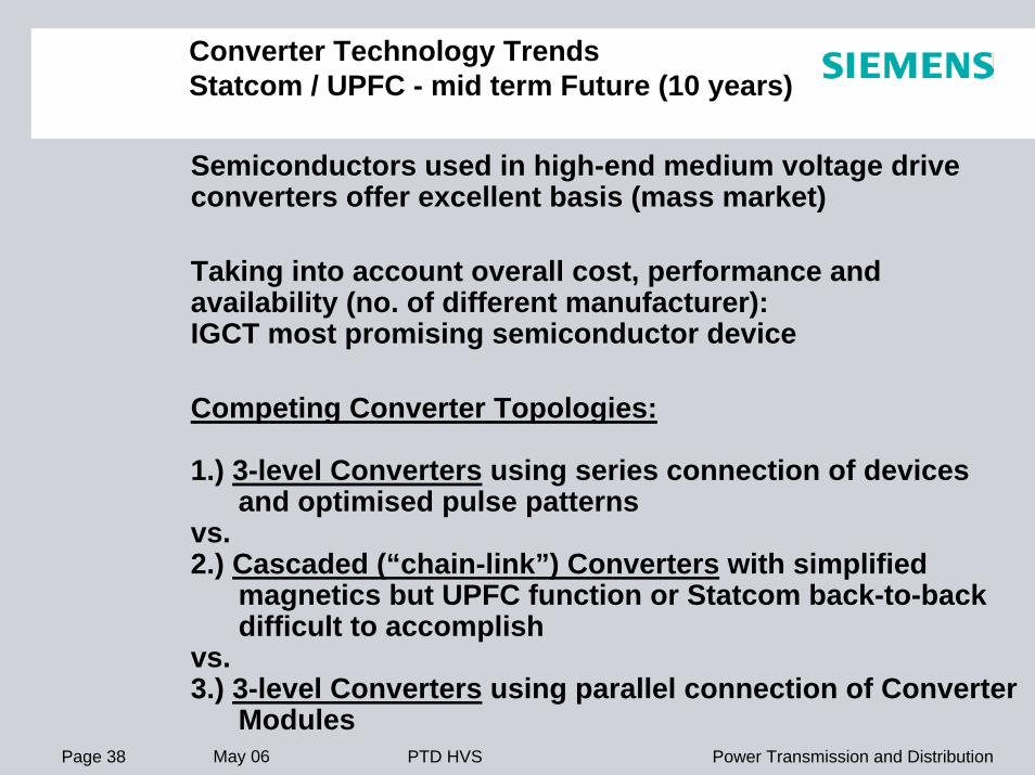
Converter Technology TrendsStatcom / UPFC - mid term Future (10 years)
Semiconductors used in high-end medium voltage drive converters offer excellent basis (mass market)
Taking into account overall cost, performance and availability (no. of different manufacturer): IGCT most promising semiconductor device
Competing Converter Topologies:
1.) 3-level Converters using series connection of devicesand optimised pulse patterns
vs. 2.) Cascaded (“chain-link”) Converters with simplified
magnetics but UPFC function or Statcom back-to-backdifficult to accomplish
vs.3.) 3-level Converters using parallel connection of Converter
Modules

Page 39 May 06 Power Transmission and DistributionPTD HVS
Siemens – Beta Experience

Page 40 May 06 Power Transmission and DistributionPTD HVS
Adelanto 0/+388Mvar SVC, USA

Page 41 May 06 Power Transmission and DistributionPTD HVS
SCCLSCCL
ApplicationsApplications
ConclusionsConclusions
SCCL from Siemens - The Solution of the 21st Century
Page 42 May 06 Power Transmission and DistributionPTD HVS
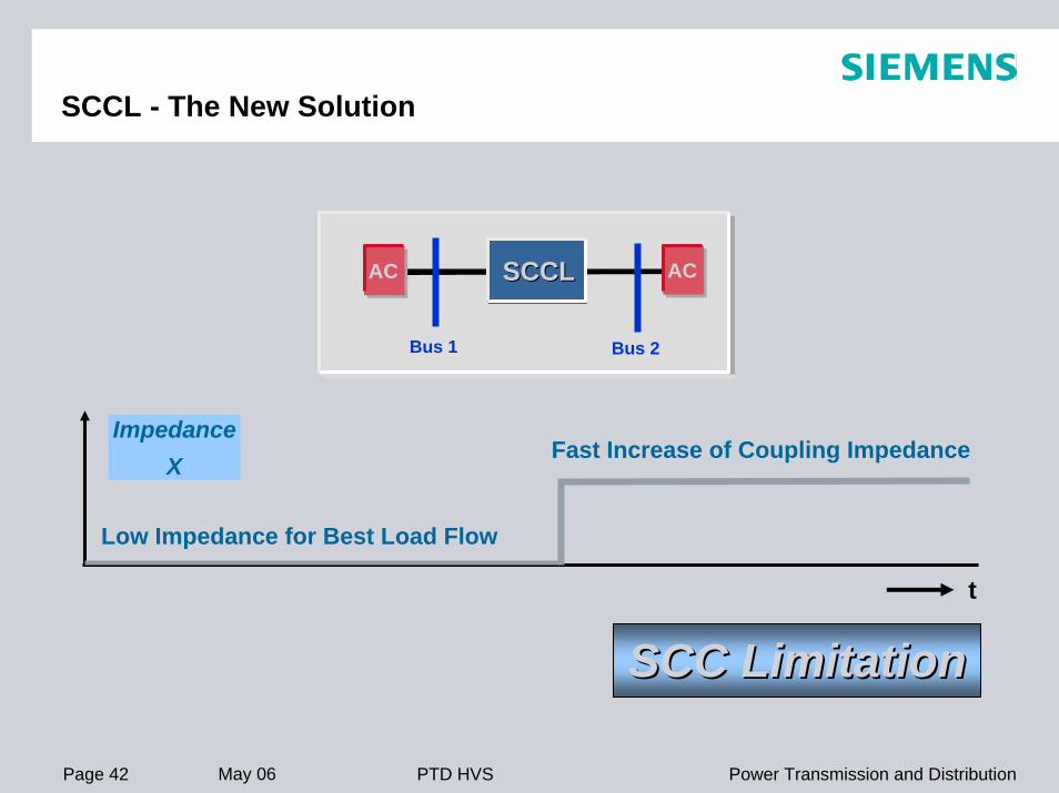
SCCL - The New Solution
Bus 1
ACAC
Bus 2
SCC LimitationSCC Limitation
SCCLSCCL
ImpedanceX
Low Impedance for Best Load Flow
Fast Increase of Coupling Impedance
t

Page 43 May 06 Power Transmission and DistributionPTD HVS
SCCL versus Conventional Reactor
Only Current Limiting Reactor ?Only Current Limiting Reactor ?Voltage Drop - needs Compensation
SCCL SCCL -- The better Alternative:The better Alternative:No Risk of Voltage CollapseReactive Power remains balanced
No Impact on Grid Load Flow
Increase of First Swing Stability
Dynamic Add-Ons for SSR & Power Oscillation Damping
Mechanically or ThyristorSwitched CapacitorBus 1
ACAC
Bus 2
Bus 1 Bus 2
AC AC

Page 44 May 06 Power Transmission and DistributionPTD HVS
SCCL - Examples of Applications
Bus 1 Bus 2
System designed for 3 Infeeds
115 kV 3 ~
Existing
3 ~
3 ~
Existing

Page 45 May 06 Power Transmission and DistributionPTD HVS
SCCL - Examples of Applications
Bus 1 Bus 2
System designed for 3 Infeeds
115 kV 3 ~
Existing
3 ~
3 ~
Expansion
3 ~
Existing

Page 46 May 06 Power Transmission and DistributionPTD HVS
SCCL - Examples of Applications
Bus 1 Bus 2
System designed for 3 Infeeds
Excess of allowed SCC LevelsExcess of allowed SCC Levels
115 kV
3 ~
Expansion
3 ~
Existing
3 ~
Existing
3 ~

Page 47 May 06 Power Transmission and DistributionPTD HVS
SCCL - Examples of Applications
SCCLSCCL
Bus 1 Bus 2
SCC LimitationSCC Limitation
System now designed for 4 Infeeds
115 kV
Enables Connection of Enables Connection of additional Generation additional Generation on the 115 kV Systemon the 115 kV System
3 ~
Existing
3 ~
Existing
3 ~
3 ~
Expansion

Page 48 May 06 Power Transmission and DistributionPTD HVS
SCCL - Designed for maximal Availability
Not with Siemens Technology:Not with Siemens Technology:High PowerHigh Power LTT ThyristorLTT Thyristor -- 110 kA peak,110 kA peak, self coolingself coolingProtection withProtection with SIMATICSIMATIC--TDCTDC -- aa standard standard in HVDC, FACTS and in HVDC, FACTS and
DrivesDrivesMeasurements Measurements -- redundantredundant (optically powered)(optically powered)no auxiliary power suppliesno auxiliary power supplies on the platform neededon the platform needed
transducerstransducers
SCCL: designed for harsh Environment & Multiple Fault Contingencies
The Operation Principle:The Operation Principle:Fail safeFail safe -- thyristor will be shorted in case of malfunctionthyristor will be shorted in case of malfunctionBackup byBackup by waferwafer--integrated overintegrated over--voltage protectionvoltage protectionFast switch onFast switch on -- instead of delayed switch offinstead of delayed switch offRedundantRedundant number ofnumber of thyristorsthyristorsMinimal steady state lossesMinimal steady state losses (reactor)(reactor)Minimal MaintenanceMinimal Maintenance -- 10 h10 h per year (0.1 % ) per year (0.1 % )
GIL - Gas-InsulatedTransmission Line

Page 50 May 06 Power Transmission and DistributionPTD HVS
2 systems 420/550 kVTunnel diameter 3 m
Arrangement in a Tunnel

Page 51 May 06 Power Transmission and DistributionPTD HVS
Installed length: 30 km; up to now all in service without any failure
References Worldwide 1974 - 1998

Page 52 May 06 Power Transmission and DistributionPTD HVS
54
3,5 m
2,8
1 600 MVA Transformer Rated Voltage 420 kV2 Encapsulated Surge Arrestors Rated Impulse3 Transfer Switching units Withstand Voltage 1640 kV4 GIL Connection Rated Current 2000/2500 A5 Open Air Surge Arrestor Rated Short-Time Current 53 kA6 Overheadline
Example of a GIL Connection: Wehr, GermanyCommissioning: 1975, Tube length 4 km

Page 53 May 06 Power Transmission and DistributionPTD HVS
Rated Voltage 550 kVRated Impulse Withstand Voltage 1550 kVRated Current 4000 / 6300 / 8000 ARated Short-Time Current 100 kA
Example of a GIL Connection: Bowmanville, CanadaCommissioning: 1985-87 Tube length 2.5 km

Page 54 May 06 Power Transmission and DistributionPTD HVS
Rated voltage 420 / 550 kVImpulse withstand voltage 1425 / 1600 kVRated current 3150 / 4000 ARated short-time current 63 kA / 3 sRated transmission load 2000 / 3800 MVAOverload capability (typical) 200 %Insulation gas N2/SF6 mixture at 7 bar
Designed and tested according to IEC 61640 „HV gas-insulated transmission lines for rated voltages of 72.5 kV and above”
Technical Data of the Standard Design

Page 55 May 06 Power Transmission and DistributionPTD HVS
< 120 m
5b 5a 3 4 1 2 4 5b
1 enclosure2 inner conductor3 conical insulator4 support insulator5a male sliding contact5b female sliding contact
Straight Unit
for straight sections up to 120 m lengthbending radius up to 400 m possible

Page 56 May 06 Power Transmission and DistributionPTD HVS
£ 120 m
5 52143a
3b 3a
1 enclosure2 inner conductor3a male sliding contact3b female sliding contact4 conical insulator5 support insulator
Angle Unit
for directional changesflexible angle from 4° to 90°

Page 57 May 06 Power Transmission and DistributionPTD HVS
1 enclosure2 inner conductor3a male sliding contact3b female sliding contact4 conical insulator5 support insulator
< 120 m
3b 5 3b43b 3a2413a
Disconnector Unit
separation of gas compartmentsconnection point for sectional commissioning of the GILlocation of the decentralised monitoring units

Page 58 May 06 Power Transmission and DistributionPTD HVS
1 enclosure2 inner conductor3a male sliding contact3b female sliding contact4 conical insulator5 flexible connector6 compensator bellow
3b 3a1 2 456
Compensation Unit
Compensation of the thermal expansion of the enclosureFlexible connectors are leading the current

Page 59 May 06 Power Transmission and DistributionPTD HVS
Directly Buried GILLaying Process

Page 60 May 06 Power Transmission and DistributionPTD HVS
Angle unit
6,5 m
6,8
m
1,5
m
2,5
m
O.K.0,0
L1
L2
L1 distance between fixpoints 100 - 150 mL2 distance between shafts 1000 - 1500 m
Shaft with disconnection and compensator unit
Directly Buried GILSystem Components

Page 61 May 06 Power Transmission and DistributionPTD HVS

Page 62 May 06 Power Transmission and DistributionPTD HVS
Singlelinedrawing
1 GIL construction unit, straight2 GIL construction unit, bend R > 400 m3 Axial compensator4 Disconnecting housing with gastight insulators and
surveillance system5 Support with fixed point6 Support with sliding bearing7 Angle unit
Tunnel Top View with Direction Changes

Page 63 May 06 Power Transmission and DistributionPTD HVS
Single line drawing
1 Delivery and supply of prefabricated elements
2 Mounting and welding3 Threading of the GIL in the
tunnel4 High voltage test
Laying and Commissioning in the Tunnel

Page 64 May 06 Power Transmission and DistributionPTD HVS
Cost structure GIL Madrid, Spain
3,2
41,4
6,5
2,55,2
7,4
19
12,7
2,2
0
5
10
15
20
25
30
35
40
45
Insulat
orsOrd
er Pro
cess
ing B
erlin
Pipes, c
omponents
Logistic
s, tra
nsport
Engine
ering,
PM
Gas, s
teel, s
urge a
rreste
rsCon
struc
tion s
ite (te
ch.)
Civil w
orks
Installa
tion p
erso
nnel
%
Page 65 May 06 Power Transmission and DistributionPTD HVS
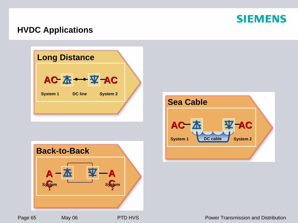
DC lineSystem 1 System 2
ACACACAC
Long Distance
Back-to-Back
System 1
System 2
AACC
AACC
DC cable
ACAC ACACSystem 2System 1
Sea Cable
HVDC Applications

Page 66 May 06 Power Transmission and DistributionPTD HVS
Bipolar
Transmission LineTerminal
ATerminal
B
Pole 1
Pole 2
Monopolar
Transmission LineTerminal
ATerminal
B
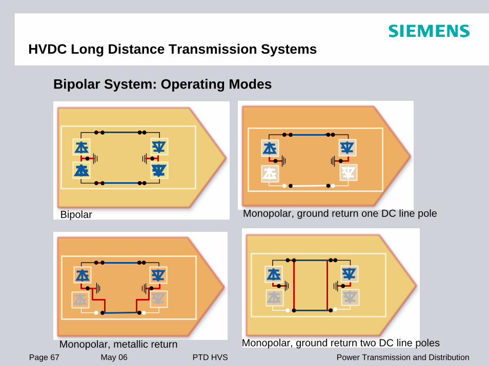
HVDC Long Distance Transmission Systems
Page 67 May 06 Power Transmission and DistributionPTD HVS
Bipolar System: Operating Modes
Monopolar, metallic return
Bipolar Monopolar, ground return one DC line pole
Monopolar, ground return two DC line poles
HVDC Long Distance Transmission Systems

Page 68 May 06 Power Transmission and DistributionPTD HVS
Multi Terminal
Terminals in Parallel
Terminals in Series
HVDC Long Distance Transmission Systems

Page 69 May 06 Power Transmission and DistributionPTD HVS
Bipolar HVDC Terminal
6 DC Switchyard
1 AC Switchyard
2 AC Filters, Capacitor Bank
3 Converter Transformers
4 Thyristor Valves
5 Smoothing Reactorsand DC Filters
66
Pole 1
Pole 2
Controls, Protection, Monitoring To/ fromotherterminal
System 1 System 2
ACACACAC AC
11 22
ACfilter
33 44 55
DCfilter
DCfilter

Page 70 May 06 Power Transmission and DistributionPTD HVS
HVDC Back-to-Back Station
1 AC Switchyard
2 AC Filters, Capacitor Bank
3 Converter Transformers
4 Thyristor Valves
5 Smoothing Reactors
System 2
ACACACAC
11 22 33 44 55
Controls, Protection, Monitoring
44 33 22 11
ACfilter
ACfilter
System 1

Page 71 May 06 Power Transmission and DistributionPTD HVS
ValveBranch
ValveTower
Thyristors ValvesPrinciple Circuit of a 12-pulse Group

Page 72 May 06 Power Transmission and DistributionPTD HVS
Mechanically tailored to replace a 133kV mercury arc valve
Thyristor Valves133kV Valve in Commercial Operation

Page 73 May 06 Power Transmission and DistributionPTD HVS
Tian - Guang
HVDC Bipolar Long Distance Transmission
PN = 2 x 900 MW, VDC = ±500 kV
Converter Transformer: Tian - Guang
Page 74 May 06 Power Transmission and DistributionPTD HVS
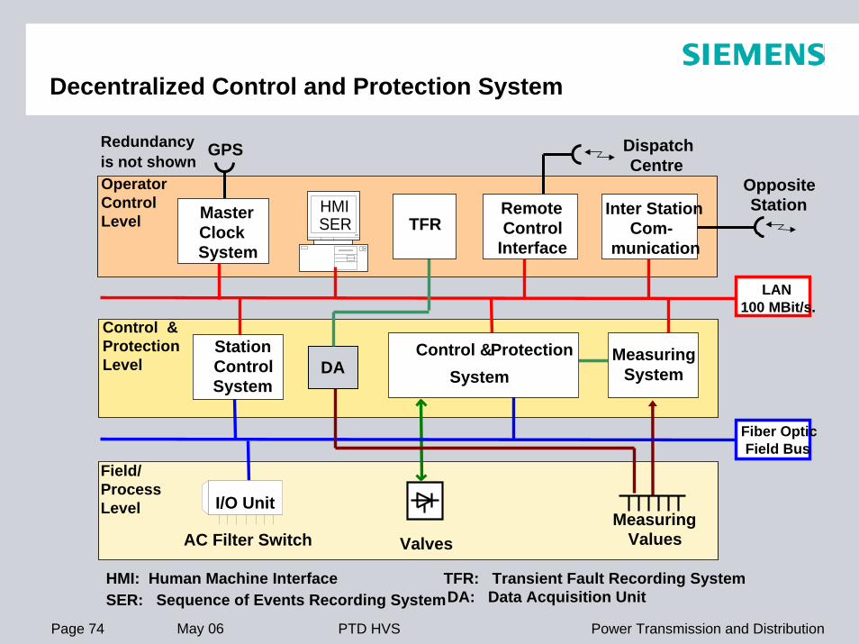
Decentralized Control and Protection System
OperatorControlLevel
Control &ProtectionLevel
Field/ProcessLevel
Valves
DA: Data Acquisition Unit
MeasuringValues
GPS
MasterClockSystem
HMI: Human Machine InterfaceSER: Sequence of Events Recording System
HMISER
DispatchCentre
RemoteControl
Interface
OppositeStationInter Station
Com-munication
Fiber OpticField Bus
AC Filter Switch
I/O Unit
Redundancyis not shown
DA
LAN100 MBit/s.
StationControlSystem
Control &System
Protection MeasuringSystem
TFR: Transient Fault Recording System
TFR

Page 75 May 06 Power Transmission and DistributionPTD HVS
Basic HVDC Control Functions
AC System A AC System B
U2U1
Id
Reactive Power Control
ReactivePowerControl
ReactivePowerControl
RectifierControl
Id-Control
Converter
Id: DC CurrentConverter Control
InverterControl
Ud-Control
Converter
Ud: DC Voltage
ACF
ACFACF
ACF
ACF: AC FilterTap Changer Control
Tap ChangerControl
Tap ChangerControl

Page 76 May 06 Power Transmission and DistributionPTD HVS
Hybrid-Optical DC Current Measuring
Shunt
Sensor HeadBox

Page 77 May 06 Power Transmission and DistributionPTD HVS
Win-TDC/SIMATIC TDC - Modules
All Control and DC Protection systems use the high-performance control system SIMATIC TDC (Less Spare Parts!)Systems are used worldwide in various applicationsEstimated product life cycle of more than 25 yearsFlexible interface systems make Win-TDC also the solution for HVDC Control and Protection refurbishment projects

Page 78 May 06 Power Transmission and DistributionPTD HVS
China National Technical Import &Export Corporation (CNTIC)GeshaGezhouba(Central China)Nan Qiao(40 km from Shanghai)1200 MW, bipolar± 500 kV DC, 525/230 kV, 50/50 HzLong-distance transmission, about 1000 km 5.5 kV5760
Customer:
Project name:Location:
Power rating:Voltage level:
Type of plant:
Thyristor voltage:Nos. of thyristors:
Gezhouba - Shanghai, China, 1989

Page 79 May 06 Power Transmission and DistributionPTD HVS
TianshengqiaoGuangzhou Beijiao
Tian Guang, China, 2000

Page 80 May 06 Power Transmission and DistributionPTD HVS
State Power South CompanyGuizhou -GuangdongGuizhou Province and Guangzhou near HongkongLong-distancetransmission3000 MW, bipolar980km± 500 kV DC, 525 kV 50Hz8 kV (LTT)3744
Customer:
Project name:
Location:
Type of Plant:
Power Rating:Transmission dist.:Voltage levels:
Thyristor voltage:Nos. of thyristors
Guizhou - Guangdong, China, 2004

Page 81 May 06 Power Transmission and DistributionPTD HVS
China Southern Power Grid Co.Guizhou –Guangdong #2Guizhou Province & Guangzhou near Hong KongLong-DistanceTransmission3000 MW, bipolar980km±500kV DC, 525kV 50Hz
Customer:
Project name:
Location:
Type of Plant:
Power Rating:Transmission dist.:Voltage levels:
Guizhou – Guangdong #2 HVDC Project, China
Contact Signed in May 2005

Page 82 May 06 Power Transmission and DistributionPTD HVS
World's first HVDC Submarine Cable Link with Direct Light Triggered Thyristor in Commercial Operation
Moyle, Northern Ireland, 2001

Page 83 May 06 Power Transmission and DistributionPTD HVS
Neptune RTS, USA, 2007
Customer:End User:
Location:
Project Development:
Supplier:
Type of Plant:Power rating:Transmission dist.:
Neptune RTSLong Island Power Authority (LIPA)New Jersey: SayrevilleLong Island: Duffy Avenue
NTP-Date: 06/2005PAC: 07/2007ConsortiumSiemens / PirellíSea Cable600/660 MW Monopolar82 km DC Sea Cable23 km Land Cable

Page 84 May 06 Power Transmission and DistributionPTD HVS
Trans Bay Cable Project, USA
Babcock & Brown
Trans Bay Cable
San Francisco Bay Area
Project Development, NTP late 05/ early 06Exclusivity AgreementB&B, Siemens, PirelliLong DistanceSea Cable400…600 MW monopolar
App. 55 miles
Customer:
Project name:
Location:
Project Status:
Project Team:
Type of Plant:
Power rating:
Transmission dist.:

Page 85 May 06 Power Transmission and DistributionPTD HVS
Lamar, Colorado, USA, 2004

Page 86 May 06 Power Transmission and DistributionPTD HVS
Back to Back – Conventional HVDC Transformers
130 ≤ kV ≤ 550300 ≤ MW < 1200130 ≤ kV ≤ 550
300 ≤ MW < 1200
B2B - Rating:
Filters Filters
System 1System 1 System 2System 2Power & Voltage ControlFault Current Blocking
Typically for asynchronous Systems
Typically for asynchronous Systems

Page 87 May 06 Power Transmission and DistributionPTD HVS
Lamar Colorado-Xcel Energy - 210 MW BtB Station

Page 88 May 06 Power Transmission and DistributionPTD HVS
BTB- an Option with 2 AC Transformers
BTB With Transformers on both Sides
AC System 1
ungrounded Y or Δ
Filters
Smoothing
Reactor
Filters
AC System 2Six-
Pulse Bridges
Smoothing
Reactor

Page 89 May 06 Power Transmission and DistributionPTD HVS
BTB (AC Transformers)- Conclusion & Summary of Benefits
Conventional AC TransformersConventional AC Transformers are usedare usedHigher ReliabilityHigher Reliability (no DC Stress, no (no DC Stress, no TapchangerTapchanger))Shorter Delivery TimeShorter Delivery TimeReduced CostsReduced Costs
AC AC Filters Filters can be installed can be installed at the valve sideat the valve side of the transformerof the transformerReduced Transformer RatingReduced Transformer Rating
TripleTriple--tuned AC Filterstuned AC Filters reduce the Number of Switchgear and reduce the Number of Switchgear and Protection EquipmentProtection Equipment
Light triggered ThyristorsLight triggered Thyristors provide increased Reliability and provide increased Reliability and improved Performanceimproved PerformanceUsing a standard design & preUsing a standard design & pre--assembled Solutionassembled Solutionfor Valves, Controls and Protection reduces site work, for Valves, Controls and Protection reduces site work, Erection and Commissioning TimeErection and Commissioning Time
BTB (AC Transformers) - the new Solution

Page 90 May 06 Power Transmission and DistributionPTD HVS
Intelligent Solutions for Power Transmission
with with HVDC & HVDC &
FACTS FACTS from from
SiemensSiemens
Thank You for your Attention!