application of new control strategy for sun trackingrubio/ecm_07_solar.pdf · application of new...
TRANSCRIPT
www.elsevier.com/locate/enconman
Energy Conversion and Management 48 (2007) 2174–2184
Application of new control strategy for sun tracking
F.R. Rubio *, M.G. Ortega, F. Gordillo, M. Lopez-Martınez
Depto. Ingenierıa de Sistemas y Automatica, Escuela Superior de Ingenieros, Universidad de Sevilla, 41092 Sevilla, Spain
Received 12 June 2006; accepted 24 December 2006Available online 26 February 2007
Abstract
The application of high concentration solar cells technology allows a significant increase in the amount of energy collected by solararrays per unit area. However, to make it possible, more severe specifications on the sun pointing error are required. In fact, the perfor-mance of solar cells with concentrators decreases drastically if this error is greater than a small value. These specifications are not fulfilledby simple tracking systems due to different sources of errors (e.g., small misalignments of the structure with respect to geographicalnorth) that appear in practice in low cost, domestic applications.
This paper presents a control application of a sun tracker that is able to follow the sun with high accuracy without the necessity ofeither a precise procedure of installation or recalibration. A hybrid tracking system that consists of a combination of open loop trackingstrategies based on solar movement models and closed loop strategies using a dynamic feedback controller is presented. Energy savingfactors are taken into account, which implies that, among other factors, the sun is not constantly tracked with the same accuracy, toprevent energy overconsumption by the motors. Simulation and experimental results with a low cost two axes solar tracker are exposed,including a comparison between a classical open loop tracking strategy and the proposed hybrid one.� 2007 Elsevier Ltd. All rights reserved.
Keywords: Closed loop control; Sun tracking strategy; Low cost two axes solar tracker; Robust performance
1. Introduction
Thanks to the technical advances, reasonable pricedhigh concentration solar photovoltaics (PV) arrays are sup-posed to be available within a close time. However, thefuture use of this kind of solar PV arrays in low cost instal-lations will bring a new type of problem: the necessity ofhigh accuracy solar pointing. High concentration solarPV arrays require greater solar tracking precision than con-ventional photovoltaic arrays, and therefore, a relativelylow pointing error must be achieved for this class of instal-lations. Since, in large plants, the design and installation isoptimized, they can usually achieve this low error require-ment. Nevertheless, the cost of such optimization is prohib-itive for low cost installations.
0196-8904/$ - see front matter � 2007 Elsevier Ltd. All rights reserved.
doi:10.1016/j.enconman.2006.12.020
* Corresponding author. Tel.: +34 9 54487350; fax: +34 9 54487540.E-mail addresses: [email protected] (F.R. Rubio), [email protected]
(M.G. Ortega), [email protected] (F. Gordillo), [email protected] (M.Lopez-Martınez).
This paper discusses the design and implementation of acontrol algorithm for a low cost mechanical structure thatcan support photovoltaic modules and that acts as a suntracker.
Several classes of structure can be distinguished depend-ing on the classification criteria:
• Regarding movement capability, three main types of suntrackers exist [1]: fixed surfaces, one axis trackers (see[2]) and two axes trackers (see [3]). The main differenceamong them is the ability to reduce the pointing error,increasing the daily irradiation that the solar cellsreceive and, thus, the electric energy that they produce.A theoretical comparative study between the energyavailable to a two axes tracker, an east–west trackerand a fixed surface was presented in [4]. As main results,it concluded that the annual energy available to the idealtracker is higher by 5–10% and 50% than the east–westtracker and the fixed surface, respectively.

F.R. Rubio et al. / Energy Conversion and Management 48 (2007) 2174–2184 2175
• Regarding control units, the main types of solar trackersare [5]: passive, microprocessor and electro-optical con-trolled units. The first ones do not use any electroniccontrol or motor (see [6]). The second ones use mathe-matical formulae to predict the sun’s movement andneed not sense the sunlight. An example of this kindof unit can be found in [3]. Finally, the electro-opticalcontrolled units that use the information of some kindof sensor (e.g., auxiliary bifacial solar cell panel, pyrhe-liometer) to estimate the sun’s real position is used in thecontrol algorithm (see [2,7]).
This paper presents a control strategy for two axestrackers that is executed in a microprocessor. Correctpointing is inferred from the generated electrical power,which must be sensed on line.
The proposed control strategy consists of a combinationbetween: (1) An open loop tracking strategy, which corre-sponds to the microprocessor controller in the classification[5]. This controller is based on a solar movement model. (2)A closed loop strategy, which corresponds to the electro-
optical controller in the previous classification. This strat-egy consists of a dynamic controller that feeds back gener-ated power measurements.
Furthermore, in order to make the system autonomous,a search mode that operates when the tracking error is toolarge is included. To prevent the system from going into thesearch mode too often, a reduced table of errors (updatedevery half an hour if there is enough radiation) is alsostored.
The main differences between this strategy and the onespresented in other works, such as [7] or [8], with similarpurposes are the following:
• Those works deal with open loop control and with esti-mated pointing errors. These errors are stored for lateranalysis. Thus, those strategies do not use on line feed-back control, while ours uses a dynamic controller.
• A large amount of memory is needed to hold the storederror database in those works. This problem would bemore serious if a two axes tracker was used. This factrequires that new hardware be used for control pur-poses. Thereby, those algorithms are not useful when asmall amount of memory is available. In this case, thecombination of on line feedback control and a quitesmall error table is more than sufficient to make the sys-tem work with the required precision.
• In addition, energy saving factors are taken into accountin the proposed strategy. This implies that, among otherfactors, the sun is not constantly tracked with the sameaccuracy to prevent energy overconsumption by themotors.
The control algorithm takes into account the differenttypes of errors that can appear in practice in low costdomestic systems, e.g., the placement and problems withthe mechanical structure and errors of time and location.
As a result, whatever the type of error, the controller canmake the tracker follow the sun. In fact, the proposed algo-rithm is also valid for large high precision trackers since itcontributes to decreasing these errors.
In summary, there are three main aspects concernedwith this control strategy:
• A new sun tracking strategy for low cost positionerswith two degrees of freedom was developed.
• A simulator that allows us to evaluate how the trackingstrategy is working as well as to program other strategieswas built.
• A mechanical structure that acts as a solar tracker and amonitoring and positioning control system for twodegrees of freedom was built (see pictures of the trackerin Fig. 11).
The remainder of the paper is organized as follows: thetracking strategy is explained in detail in Section 2. Section3 describes the structure of the control system. Experimen-tal results, including a comparison between an open loopand the proposed hybrid strategies, are shown Section 4.Finally, the main conclusions of this work are drawn inSection 5.
2. Automatic tracking strategy
A hybrid tracking strategy that basically consists of twomodes was used: in one mode, normal sun tracking is per-formed, maintaining a tracking error less than a pre-speci-fied value. In the other, a sun search is undertaken bymeans of an ever widening rectangular spiral; this is neces-sary when the sun needs to be located because of someexternal disturbance (for example, a period of prolongedcloudiness). Each of these modes is described in greaterdetail below.
2.1. Normal tracking mode
This mode is in effect whenever the sun tracking error issmaller than a specified bound and the solar radiation greatenough for the system to produce electric energy.
It is a hybrid tracking system that consists of a combi-nation of open loop tracking strategies based on solarmovement models (feedforward control) and closed loopcontrol strategies using a feedback controller. The feed-back controller is designed to correct the tracking errorsmade by the feedforward controller in the open loopmode. The operation in this mode is shown schematicallyin Fig. 1.
In this figure, u represents the position (azimuth and ele-vation) the tracking system assumes is the location of thesun. It can be seen that this estimated position of the sunis obtained by adding two values: �u, which is the positionobtained from the equations that model the sun’s move-ment, and ~u, which is a correction of that position basedon the estimated position of the sun, �y.

Controller
Sensor
y
+
+
Disturbances
SolarEquations
MotorsControl
-
+
Pedestal
Sun
y-
uu~
y
u-
Fig. 1. Operation in tracking mode.
Sun
Pedestalreference
Initialtolerance
Finaltolerance
time
degr
ees
Fig. 2. Basic scheme for the movement of the mechanical structure.
2176 F.R. Rubio et al. / Energy Conversion and Management 48 (2007) 2174–2184
There are several algorithms for calculating the positionof the sun ð�uÞ based on the date and time provided by anauxiliary clock and geographical data (longitude and lati-tude of the point used to estimate the position of thesun). This work used the PSA algorithm, developed bythe Plataforma Solar de Almerıa [9], which has improvedthe calculation of universal time as well as the treatmentof leap years and which also makes the calculation morequickly and robustly, eliminating unnecessary operationsby using simple, valid equations in both hemispheres.
However, despite the precision of this algorithm, errorsin the estimation of the sun’s position are possible for sev-eral reasons, such as variations in the time given by theauxiliary clock with regard to actual solar time, lack of pre-cision in the geographical location of the driver (errors inthe estimation of latitude and longitude, although they usu-ally are small if GPS technology is used), and errors in thealignment of the mechanical structure with respect to geo-graphical north (different from magnetic north). In fact,this last kind of error is very frequent in low priced instal-lations if no specialized staff is employed for setup adjust-ment, or if the wind causes any misalignment.
This fact justifies the necessity of including a correctionð~uÞ for the sun’s feedforward position ð�uÞ in order to obtaina better estimate of its real position (u), especially when it isimportant for the tracking error to be very low, as is thecase here. This correction is provided by the Controller,which will be analyzed later.
Once a realistic estimate of the sun’s position is obtained(u), the Motors Control block gives the necessary com-mands to the motors driver in order to move the platformaccording to the solar trajectory. For energy reasons, as themain objective of the strategy is the generation of energyusing the sun as a source, the tracker is not commandedto follow the sun at all times because this would cause con-tinuous movement of the driver motors, which would, inturn, result in excessive energy consumption. Instead, toprevent unnecessary movement of the mechanical structure(see [10,8]), the strategy implemented in the controller is thefollowing (Fig. 2): the structure does not move as long asthe tracking error (assuming that the sun is where the u sig-nal says it is) is less than a certain tolerance. When thiserror is greater than this tolerance, the controller orders
the driver to move to a point at which the sun will arrivein a certain amount of time. Thus, the tracker ‘‘waits’’for the sun. This process is identical and independent foreach axis. However, the two axes never move at the sametime: before ordering the movement of one of the axes, acheck is made to ensure that the other axis is not moving.The two axes are not allowed to move simultaneouslybecause of the type of sensor used to indicate whether thetracking of the sun is correct, as will be seen afterwards.
As the sun moves along its trajectory throughout theday, signals are sent so that the driver moves appropriately,thus generating the electrical energy that this project wasdesigned to provide. The power is used as a Sensor to con-firm that the driver is tracking the sun correctly, so adecrease in the power generated (under normal externalconditions, i.e. without taking into account extendedcloudy periods, for example) indicates tracking problems.It is known that the greater the error is in either of thetwo coordinates (azimuth and elevation), the less poweris generated. As a result, if the driver moves on either ofthe coordinates (while the other remains fixed) it can beassumed that the real position of the sun for that coordi-nate corresponds to the point where the maximum powerwas produced during that movement. This is why bothmotors cannot move simultaneously. In this way, thepower generated is used as a sensor to determine the sun’sposition.
Finally, in order to close the feedback control loop, theController block was designed, which implements a propor-tional and integral (PI) control strategy for each coordinateindependently, whose purpose is to bring about a differenceof zero between the u signal and the real position of thesun. This controller uses an estimate of this difference,which is calculated as follows: as the system moves fromone position to the next (keep in mind that the systemmoves ahead to wait for the sun), the control system sam-ples the power generated by the power sensor. It is assumedthat the point at which the maximum amount of power isproduced is equal to the position of the sun for the coordi-nate of which the mechanical structure is being oriented (aswas explained in the preceding paragraph). Thus, by com-paring the sun’s position according to this system with the
F.R. Rubio et al. / Energy Conversion and Management 48 (2007) 2174–2184 2177
value given by the corrected solar equations, the trackingerror for each axis is obtained.
The error estimate is computed taking past and presenterror measurements into account. It is defined by the PIcontroller, applied in a discrete manner:
~ukþ1 ¼ Kp ~yk þ1
T iSk
� �ð1Þ
Sk ¼ Sk�1 þ T mk~yk ð2Þ
where ~ukþ1 is the present error estimate, ~yk is the last track-ing error measurement, Sk is the integral of the time vary-ing discrete error signal, Tmk is the present sampling periodand Kp and Ti are constants tuned to give an adequate rel-ative weight to the proportional and integral parts in thecomputation of the error estimate.
Regarding the sampling process for the power signalgenerated, it should be noted that it needs to be frequentenough for us to have enough points to estimate the realposition of the sun for each coordinate with a certainamount of precision.
With regard to the PI control strategy employed in theController, it is worth noting that the control laws (onefor each coordinate) will not be executed with a constantsampling time, as is usually the case with conventional dis-crete time control systems, even though the changes in sam-pling time are small. In this case, the PI’s will only operatewhen each incremental movement of the structure has fin-ished, and the structure has reached its final referencepoint. Given that these movements are determined by acertain tolerance in the orientation error (remember thestrategy followed by the Controller) and the velocity ofthe sun (for both coordinates) is not constant throughoutthe day, the time that the structure must wait for the sun,and consequently, the corresponding PI sampling time willvary depending on the position of the sun. Furthermore,since both motors cannot move simultaneously, there is
9 9.01 9.02 9.03 9.04 9.05 9.0612.9
13
13.1
13.2
13.3
13.4
13.5
13.6
13.7
time (hours)
elev
atio
n (d
egre
es)
CEqSEqSMv
Elevation
Fig. 3. Evolution of
yet another delay in the movement of one of the motorsif the other is moving at that time.
Given the proposed control law, that the controller hasan integral effect regardless of the sampling time used andthat the variations of the sampling time are small, this con-troller will incorporate the error measured between thesun’s real position and the estimated position, u, providinga correction, ~u, that will cause the estimated position of thesun to move toward the real position. Note as well that thiscontroller provides a continuous error of almost zero whentaking into account that the usual time of the correctionperformed by the controller is well below the characteristictime of the variations in the sun’s position throughout theday.
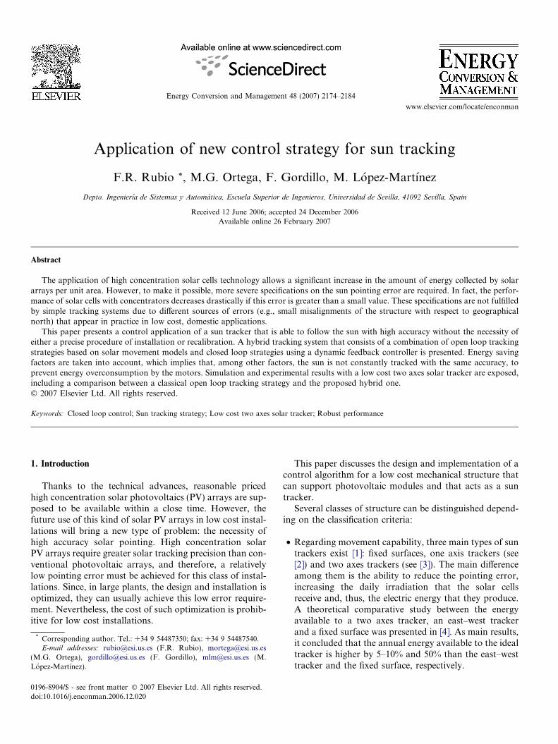
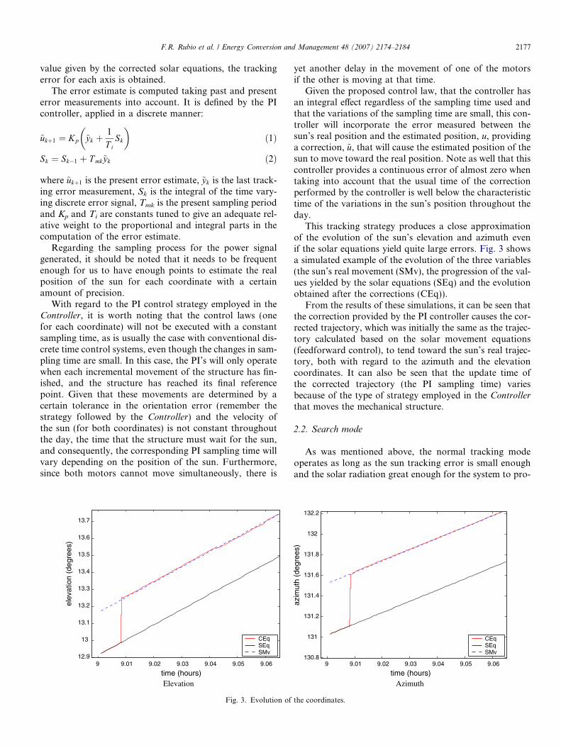
This tracking strategy produces a close approximationof the evolution of the sun’s elevation and azimuth evenif the solar equations yield quite large errors. Fig. 3 showsa simulated example of the evolution of the three variables(the sun’s real movement (SMv), the progression of the val-ues yielded by the solar equations (SEq) and the evolutionobtained after the corrections (CEq)).
From the results of these simulations, it can be seen thatthe correction provided by the PI controller causes the cor-rected trajectory, which was initially the same as the trajec-tory calculated based on the solar movement equations(feedforward control), to tend toward the sun’s real trajec-tory, both with regard to the azimuth and the elevationcoordinates. It can also be seen that the update time ofthe corrected trajectory (the PI sampling time) variesbecause of the type of strategy employed in the Controllerthat moves the mechanical structure.
2.2. Search mode
As was mentioned above, the normal tracking modeoperates as long as the sun tracking error is small enoughand the solar radiation great enough for the system to pro-
9 9.01 9.02 9.03 9.04 9.05 9.06130.8
131
131.2
131.4
131.6
131.8
132
132.2
time (hours)
azim
uth
(deg
rees
)
Azimuth
CEqSEqSMv
the coordinates.

Elevation
Azi
mut
h
initialpoint
Fig. 4. Search mode.
R<1R<1
22
2
Positioner
Fig. 5. Incorrect search step.
2178 F.R. Rubio et al. / Energy Conversion and Management 48 (2007) 2174–2184
duce electric energy, and then, the previous strategy is pos-sible. If the tracking error is larger, no electric energy isproduced, and the sensor strategy will not work. Thus,for the system to function autonomously, how the systemwill react when one of these premises ceases to be true alsohas to be taken into account.
This section will describe how the search mode wasdesigned. This mode will only operate when the trackingerror is not small enough but the solar radiation is greatenough for the system to produce electric energy. Note thatfor this to occur, there must be an additional solar radia-tion sensor (e.g., a pyrheliometer) that indicates whetherthe radiation exceeds the minimum threshold required.
Thus, if the sun tracking error is too great (greater than agiven upper bound) due to a combination of time errors,errors in the alignment of the mechanical structure and exter-nal disturbances, the solar arrays will not produce electricpower, and it will not be possible to feedback any informa-tion about the tracking errors. A clear example of this prob-lem would be the presence of clouds for a prolonged periodof time. During this time interval, no corrections are pro-duced as a result of feedback from the system, and the refer-ence will be that provided by the equations (in open loop)that are available when the clouds disappear. If it remainscloudy for a long enough period of time and the errors asso-ciated with the equations are great, the misalignmentbetween the sun and the position sought by the positionerwhen the structure begins to move again may be rather great.Consequently, the power sensor will not provide adequateinformation with which to correct this problem.
It is, thus, necessary to create a procedure that allowstracker to find the sun when, for whatever reason, feedbackdoes not occur. This is the search mode algorithm. Anexception is the case in which the lack of energy producedby the inverter is a result of low solar radiation (caused, forinstance, by the presence of clouds). That case will be ana-lyzed in the next section. In that case, no matter how greatthe tracking error, the search mode should not be usedbecause the low solar radiation keeps us from detectingwhen the mechanical structure is at the correct trackingpoint.
In the search mode, the movement of the structure fol-lows a square spiral in the azimuth–elevation plane in orderto try to detect the position of the sun (see Fig. 4). As themovement takes place, a check is made as to whether thesystem is generating electric power. As soon as electricpower is produced, this mode is abandoned, and the con-troller enters the normal tracking mode.
As Fig. 4 shows, the structure movement in the azi-muth–elevation plane is completely rectangular becauseof the alternation in the movement of both its mobile axes.
The amount by which the range of the movement isincreased with each step is important. Special care mustbe taken in order not to increase the distance so much asnot to detect the sun between one movement and the nextalong the same side of the spiral. If the specificationsrequire finding the sun within, for example, one degree,
an increment in the spiral too close to this value cannotbe allowed, or the risk of not detecting the sun in the firststep and having gone too far with regard to the sun’s posi-tion in the second step is taken. An example of this isshown in Fig. 5.
Thus, special care has to be taken when choosing byhow much to increment the step for the spiral. The mostdelicate point is at the end or the beginning of each stepbecause, at these points, the distance between one trajec-tory and the next is the value of the step multiplied bythe square root of two, as is shown in the figure above. Fur-thermore, it must be taken into account that during thissearch, the sun does not remain fixed but rather continuesalong its trajectory. These two circles should overlapenough in order to ensure that the sun is not by passedwithout realizing it.
2.3. Other situations
This section briefly presents the actions taken whenthe solar radiation level is lower than the minimum level

F.R. Rubio et al. / Energy Conversion and Management 48 (2007) 2174–2184 2179
established for generating electrical energy by means of thesystem.
There are different possible actions in this case, each onewith advantages and disadvantages. However, the optionof not moving the mechanical structure to follow the move-ment of the sun as long as the radiation threshold is notmet, has been chosen. The main advantage of this optionis that no energy is consumed by moving the structure;the main disadvantage is that no energy is produced untilthere is again sufficient radiation and the structure hastracked the sun.
With this strategy, the main problem comes when it istime to track the mechanical structure because during thecloudy period, there has been no feedback on the actualsolar position, i.e. the Controller block has not beenoperating.
This means that, at first, the estimated position of thesun would be the position generated using the solar equa-tions along with the last correction generated by the PIcontroller. Theoretically, there should not be any problemswith the automatic operation of the system. If the positiongiven by the solar equations is not precise enough, the sys-tem will go into the search mode until proper tracking isachieved, and then, the system will return to the normaltracking mode.
However, in practical implementation, the system mightgo into search mode too often and, thus, waste energy. Toprevent this, a small table was incorporated where, period-ically (in this case, every half hour), the calculated errorsfrom the periods when there were no clouds are stored.Simulations have shown that using this table preventsexcessive use of the search mode after prolonged cloudyperiods.
The main difference between this tracking system andother systems (e.g., [5,7,8]) is that it is not necessary to storethe errors with regard to each of the structure positions.Were this the case, it would be problematic, given that
9 9.5 10 10.5 11 11.5 1212
14
16
18
20
22
24
26
28
30
32
time (hours)
elev
atio
n (d
egre
es)
CEq Ref PMv SMv
Elevation
Fig. 6. Mechanical structure movem
there are two degrees of freedom in our system instead ofjust one, as in [8].
To illustrate the behavior of this strategy, in the follow-ing, the result of several simulations is shown, which wereperformed using the simulator described below. In the sim-ulations, there is a cloudy period between 9:00 and 11:00(solar time) approximately. Furthermore, different sourcesof error were introduced: time error, tracking errors etc.The results of two simulations are shown: one withoutand the other with the error table mentioned above. Itcan be noticed that without the table, the behavior is worsethan when the table is used. This is because, without thetable, the corrections made in the equations are not goodenough to prevent a considerable misalignment.
Fig. 6 shows simulations of the evolution of the sun(SMv) and the corrected equations (CEq, which corre-sponds with signal u in Fig. 1), as well as the movementof the mechanical structure (PMv) when the error table isnot use. Since, for clarity’s sake, the structure was kept stillduring the cloudy period (from about 9:00 to 11:00), thereis a great discrepancy between the curve for the mechanicalstructure movement and the other curves. This discrepancywill not have much of an effect because the system cannotgenerate energy when the sun is hidden by the clouds. Atthe end of the cloudy period, the structure moves towardthe sun, and except for an overshoot evident in thegraphs, the curves appear to overlap the rest of the time.The overshoot is a result of the search mode, as will be seenin Fig. 8.
When the error tables are used, the corrections as aresult of feedback are much better, and a search is unnec-essary. Thus, a series of movements is avoided that wouldconsume part of the energy generated. This can beobserved in Fig. 7.
Fig. 8 shows the same movements exposed in Figs. 6 and7 in the azimuth–elevation plane. The system starts fromsimilar initial conditions (i.e. from the search mode) in both
time (hours)
9 9.5 10 10.5 11 11.5 12130
135
140
145
150
155
160
165
azim
uth
(deg
rees
)
Azimuth
CEq Ref PMv SMv
ent without using error table.

9 9.5 10 10.5 11 11.5 1210
12
14
16
18
20
22
24
26
28
30
time (hours)
elev
atio
n (d
egre
es)
CEq Ref PMv SMv
Elevation
9 9.5 10 10.5 11 11.5 12130
135
140
145
150
155
160
165
time (hours)
azim
uth
(deg
rees
)
Azimuth
CEq Ref PMv SMv
Fig. 7. Mechanical structure movement using error table.
2180 F.R. Rubio et al. / Energy Conversion and Management 48 (2007) 2174–2184
cases. It can be seen that when the error table is notincluded, there is a great discrepancy between the valueof the corrected equations and the position of the sun atthe moment when the clouds disappear. This fact makesthe search mode necessary again. However, when the errortable is used, these discrepancies are not significant, whichimplies that a second call to the search mode is not neces-sary anymore.
Obviously, the tables of error have limited validity intime. Apart from the possible changes in origin or valuesof error, it has to be taken into account that the trajectorythat the sun follows varies as the days go by, and this var-iation is different depending on the time of the year.
After having done different simulations, if the table forwhen there is no need of a search to resume tracking afteran extended cloudy period is considered valid, it is possibleto consider about a 25–30 day margin valid when the date
130 135 140 145 150 155 160 16512
14
16
18
20
22
24
26
28
30
32
azimuth (degrees)
PMv SMv
Without using the error table
elev
atio
n (d
egre
es)
Fig. 8. Mechanical structure movements
is near the winter or summer solstices and 15–20 days whenthe date is near the spring or autumn equinoxes.
This means that after 15–20 days of continuous, totalcloudiness, when the sun comes back out, the operationwill be normal, with no need for a search. For longer peri-ods of cloudiness, a search would be necessary beforeresuming normal tracking, but in general, the system willbe adequate.
Finally, it should be noted that additional questionswere not considered, such as safety routines to preservethe mechanical structure, e.g., the inclusion of a predeter-mined defense position in which the structure would offerminimal aerodynamic resistance. The mechanical structurecould adopt this position, for instance, if wind speedsendangered the structure itself (which would also implythe inclusion of an anemometer in the sensor system) orat night, when the sun is not out.
azimuth (degrees) 130 135 140 145 150 155 160 165
12
14
16
18
20
22
24
26
28
30
elev
atio
n (d
egre
es)
Using the error table
PMv SMv
in elevation and azimuth coordinates.

F.R. Rubio et al. / Energy Conversion and Management 48 (2007) 2174–2184 2181
2.4. Simulator
To test the reliability of the different control strategies, itis necessary to do different tests, simulating, insofar as pos-sible, the environmental conditions that can be encoun-tered in reality. The simulator allows us to do that and,thus, draw conclusions that indicate the correct operationof the tracker, as well as possible improvements.
Doing different tests under different conditions forcescreation of an environment that would allow introducingthe values that define the particular characteristics for eachsituation. Thus, the introduction of changes in the data foreach simulation, as well as obtaining information fromeach one, is facilitated.
With the easy to manage graphical environment withinMatlab, it is possible to:
• Specify the longitude and latitude of the system location.• Specify the initial and final times of the simulation.• Define the different parameters that define the tracking
strategy, such as the PI constants etc.• Define the sources of tracking error using solar equa-
tions: mistakes in latitude and longitude, constant errorswith regard to orientation and elevation and time errors.
• Specify cloudy periods.
3. Control system structure
Fig. 9 shows the control system structure developed forthe positioner. This structure can be divided into two sub-systems. The first one is a low level motor control systembased on the feedback from the angular position. The sec-ond one is a high level control system based on the powerfeedback generated by the photovoltaic arrays.
The motor control subsystem takes care of the trackingof the motors according to a given reference. The loopcloses with the feedback from the position of the motors
Positioner
Supervisoryand monitoring
device
Inverter
Control unit
PV Panels
RS-485
RS-232
Encoders
Controlsignals
Power
Fig. 9. Control loop scheme.
given by the pulse readings from the encoders. This systemunderlies the high level system.
The high level system is based on the power feedbackgenerated by the photovoltaic arrays. This system imple-ments the strategy described in Section 2.
The information from the instantaneous power gener-ated by the arrays is measured by a sensor that emits a sig-nal proportional to this power. This sensor is connected tothe A/D module of the microcontroller. It continuouslyprovides the power measurement.
Furthermore, there is a Sunny Boy 700 power inverterthat allows us to transform the constant tension generatedby the arrays into AC voltage of 220 V and 50 Hz.
3.1. Monitoring and supervision system
The control unit is connected to a PC for supervisionand monitoring. A SCADA application developed in Lab-VIEW is executed using that PC. Communication isaccomplished via a serial port with an intensity loop inthe control unit. This application allows for the remoteoperation of the control unit and data visualization, as wellas the log file storage. Therefore, this is an additional mod-ule that is not essential for industrial purposes.
This system basically has three functions. The first one isto allow for the remote operation of the control unit. Thatway, any function of the control unit can be performedfrom the PC, such as the execution of movement orders.
The second function is to receive and store data from thedriver in real time. The application allows storing all thedata requested from the control unit during its operationin the log files. Finally, it also allows for remote configura-tion of the operating parameters of the control unit.
Apart from the SCADA application, there is a threedimensional model of the tracker that moves as data arereceived from the central control unit. This allows the oper-ator to follow the operation more intuitively.
3.2. Control unit software
The control unit has three operating modes: configura-tion mode, manual mode and automatic mode. In all ofthese modes, the communication between the remote mon-itoring system and the driver is working.
Before operating in the configuration and manualmodes, an initial module is executed to initiate communica-tions and peripherals. This module initializes the decodercards and the power modulation and amplification cardand establishes the initial conditions for moving on to thenormal execution mode. To initialize the decoder card,the two axes of the tracker move until the limit switchesare activated. When that happens, the pulse counters areset to 0 and the initial operation mode, i.e. the automatictracking mode, is activated.
In the configuration mode, any type of control action issent to the tracker. The axes remain fixed in the last posi-tion reached and the alignment signals of both motors

2182 F.R. Rubio et al. / Energy Conversion and Management 48 (2007) 2174–2184
are disabled. This mode allows for modification of theoperating parameters of the control unit. These parameterscan be related to the control algorithms, communicationsconfiguration or they can be movement parameters, suchas software movement limits or night position. Theseparameters can be modified using the keyboard and screenof the control unit via the RS-485 port series.
The manual mode allows moving the tracker directly. Inthis case, the control loop is only closed at the motor levels,without feedback from the power generated by the arrays.This mode is useful for position calibration and for main-tenance. Again, in this mode, the tracker can be operateddirectly or remotely.
Finally, in the automatic mode, the high level solartrajectory tracking loop is closed by feeding back thepower generated by the arrays. This measurement is
CONFIGURATION/MANUAL
Mode?
Peripherals ancommunication
initialization
START
Motorsinicialization
Commandsrecepction
Commandsprocessing
Resultstransmission
Alarmsmanagement
Datatransmission
Fig. 10. Flow diagram of t
transmitted in each control cycle to the central unit viaan RS-232 line.
The automatic mode has two routines. The first one is asupervision routine that determines which of the motorsshould move and where to, following the strategy describedin Section 2.
The second routine is that of the motor position control.In this routine, the low level loop mentioned above isimplemented. In this mode, the control unit periodicallysends data about the movement to the supervision system(time, position of the tracker, power generated by thearrays, tracking error). It is also able to respond torequests, such as the change in the operation mode or inthe frequency of data transmission.
Finally, in all of the operation modes, the system protec-tions remain active: the software movement limits, the limit
ds
Hybridtrackingstrategy
AUTOMATIC
he control application.

F.R. Rubio et al. / Energy Conversion and Management 48 (2007) 2174–2184 2183
switches, detection of motor blockage (the power supply iscut off to prevent the motors from burning out) and detec-tion of blockage in the main unit by means of a hardwarewatchdog.
A general flow diagram of the control application isshown in Fig. 10.
4. Experimental results
The operation of the prototype of the control unit devel-oped was tested using the mechanical structure shown inFig. 11. This low cost positioning system is located onthe roof of the Department of Systems and Automatic Con-
trol Engineering Laboratories at the University of Seville, inSpain. It was checked to make sure that it worked cor-rectly, with regard to both hardware (movement of bothaxes, decoding etc.) and software (execution of basic pro-grams, monitoring etc.).
As can be seen in Fig. 11, the positioning system sup-ports flat plate PV arrays instead of concentrating PV sys-
Fig. 11. Mechanical structu
10 11 12 13 14 15 16 17 1820
30
40
50
60
70
80
90
100
110
time (hours)
pow
er (
W) hybrid strategy
open loop strategy
Electric power generated
2
Fig. 12. Experimental results using an open
tem. Since high concentration solar arrays were notavailable, several cells of slender built tubes were mountedon the arrays. These cells guarantee that no solar radiationgets to the arrays when the tracking error is greater thansome degrees.
The different strategies tested in simulation were per-formed in the control unit in order to fine tune the control-lers. In order to check the robustness of the algorithms,several error sources were included in the experiments, suchas an offset in the time given by the auxiliary clock and amisalignment on the mechanical structure orientation withrespect to geographical north.
Fig. 12 shows the experimental power attained using theopen loop tracking strategy, as well as the one obtainedusing the proposed hybrid strategy. Solar radiation graphsare also included, showing that the experiments were per-formed under similar solar radiation conditions duringthe first four hours. In this period of time, the electricpower generated using the hybrid strategy is, in mean val-ues, 55% higher than the open loop one.
re of the solar tracker.
10 11 12 13 14 15 16 17 18400
500
600
700
800
900
1000
1100
time (hours)
sola
r ra
diat
ion
(W/m
)
hybrid strategy
open loop strategy
Solar radiation
-loop and the proposed hybrid strategy.
2184 F.R. Rubio et al. / Energy Conversion and Management 48 (2007) 2174–2184
It can be observed that the power generated by the solararrays using the open loop strategy has a maximum levelabout 65 W during almost two hours at noon. However,the positioner loses the sun in the afternoon and after-wards. This implies that the cells of slender built tubesthrow shadow upon some solar cells, with the consequentdecreased level of the electric power generated.
The above mentioned fact does not happen when theproposed hybrid tracking strategy is used. Besides that,the level of generated power is about 90 W at noon (a ben-efit of about 40% with respect to the open loop strategy,despite the low quality of the mechanical structure). Addi-tionally, the arrays not only do not lose the sun but alsotheir alignments are corrected, with the consequent incre-ment of electric power generated (with a maximum greaterthan 100 W).1
5. Conclusions
A new sun tracking strategy that provides small suntracking errors (needed, e.g., by high concentration solararrays) has been developed. The algorithm consists oftwo tracking modes: a normal tracking mode, used when-ever the sun tracking error is small enough and the solarradiation is great enough; and a search mode, which oper-ates as long as the first of the above conditions is not ful-filled, but there is sufficient solar radiation to produce aminimum amount of electric power. Energy saving factorshave been taken into account in the tracking strategydesign. Simulated and experimental results have been pre-sented that show the benefits of the new strategy withrespect to a classical open loop strategy when errors inthe estimation of the sun’s position (such as variations inthe time given by the auxiliary clock or lack of precisionin the alignment of the mechanical structure with respectto geographical north) are included.
1 The reader may be surprised that the amount of generated power is solow. This is due to the fact that the experiments were conducted using aconstant non-optimal electric load. Of course, the level of power couldhave been increased if a MPPT (maximum power point tracking) devicehad been used (see, for example, [11] and references therein). However,since the goal of these experiments is to evaluate the sun’s pointing errorusing different tracking strategies, the comparison between the level ofgenerated power was taken into consideration, but not the level of powerper se.
Acknowledgements
The authors would like to acknowledge MEC-FEDERfor funding this work under grants DPI2004-06419 andDPI2006-07338. They also would like to thank Oscar Col-lazo and Oscar Pereles for their collaboration in conduct-ing the tests and Ignacio Luque for many helpfulsuggestions during the project IFICLES.
References
[1] Helwa NH, Bahgat ABG, El Shafee AMR, El Shanawy ET.Maximum collectable solar energy by different solar tracking systems.Energy Sources 2000;22(1):23–34.
[2] Poulek V, Libra MA. Very simple solar tracker for space andterrestrial applications. Solar Energy Mater Solar Cells2000;60:99–103.
[3] Abdallah S, Salem N. Two axes sun tracking system with PLCcontrol. Energy Convers Manage 2004;45(11–12):1931–9.
[4] Neville RC. Solar energy collector orientation and sun tracking mode.Solar Energy 1978;20(1):7–11.
[5] Roth P, Georgiev A, Boudinov H. Cheap two axis sun followingdevice. Energy Convers Manage 2005;46(7–8):1179–92.
[6] Clifford MJ, Eastwood D. Design of a novel passive solar tracker.Solar Energy 2004;77(3):269–80.
[7] Roth P, Georgiev A, Boudinov H. Design and construction of asystem for sun-tracking. Renewable Energy 2004;29(3):393–402.
[8] Sala G, Anton I, Arborio JC, Luque A, Camblor E, Mera E, et al.The 480 kWP EUCLIDESTM – Thermie Power Plant: Instalation, set-up and first results. In: Proceeding of the 16th European photovoltaicsolar energy conference and exhibition, WIP – Stephens & Associates,Glasgow, Scotland, May, 2000.
[9] Blanco-Muriel M, Alarcon-Padilla DC, Lopez-Moratalla T, Lara-Coira M. Computing the solar vector. Solar Energy2001;70(5):431–41.
[10] Baltas P, Tortoreli M, Russel P. Evaluation of power output for fixedand step tracking photovoltaic arrays. Solar Energy1986;37(2):147–63.
[11] Hua C, Lin J. A modified tracking algorithm for maximum powertracking of solar array. Energy Convers Manage 2004;45(6):911–25.