application of computational fluid dynamics for
TRANSCRIPT

Draft
Application of Computational Fluid Dynamics for Thermohydrodynamic Analysis of High-Speed Squeeze-Film
Dampers
Journal: Transactions of the Canadian Society for Mechanical Engineering
Manuscript ID TCSME-2018-0060.R1
Manuscript Type: Article
Date Submitted by the Author: 03-Sep-2018
Complete List of Authors: Perreault, Maxime; University of TorontoHamzehlouia, Sina; University of Toronto, Mechanical and Industrial EngineeringBehdinan, Kamran; University of Toronto, Mechanical and Industrial Engineering
Keywords: Squeeze Film Damper, Thermohydrodynamics, Computational Fluid Dynamics, High-Speed Turbomachinery
Is the invited manuscript for consideration in a Special
Issue? :Not applicable (regular submission)
https://mc06.manuscriptcentral.com/tcsme-pubs
Transactions of the Canadian Society for Mechanical Engineering

Draft
1
Application of Computational Fluid Dynamics for Thermohydrodynamic Analysis of High-Speed Squeeze-Film
Dampers
Advanced Research Laboratory for Multifunctional Lightweight Structures
University of Toronto, Department of Mechanical and Industrial Engineering,
5 King's College Rd., Toronto, Ontario, M5S 3G8, Canada
Maxime PerreaultB.A.Sc. Student,
Sina HamzehlouiaCorresponding Author Postdoctoral Fellow,
[email protected], Tel: +1 (416) 834- 1817
Kamran BehdinanProfessor,
[email protected], Tel: +1 (416) 946-3631
Page 1 of 49
https://mc06.manuscriptcentral.com/tcsme-pubs
Transactions of the Canadian Society for Mechanical Engineering

Draft
2
Abstract
In high-speed turbomachinery, the presence of rotor vibrations, which produce
undesirable noise or shaft deflection and losses in performance, has brought up the need for the
application of a proper mechanism to attenuate the vibration amplitudes. Squeeze-film dampers
(SFD) are a widely employed solution to the steady-state vibrations in high-speed
turbomachinery. SFDs contain a thin film of lubricant which is susceptible to changes in
temperature. For this reason, the analysis of thermohydrodynamic (THD) effects on the SFD
damping properties is essential. This paper develops a CFD model to analyze the THD effects in
SFDs, and enabling the application of CFD analysis to be a base-line for validating the accuracy
of analytical THD SFD models. Specifically, the CFD results are compared against numerical
simulations at different operating conditions, including eccentricity ratios and journal whirl
speeds. The comparisons demonstrate the effective application of CFD for THD analysis of
SFDs. Additionally, the effect of the lubricant THDs on the viscosity, maximum and mass-
averaged temperature, as well as heat generation rates inside the SFD lubricant are analyzed. The
temperature of the lubricant is seen to rise with increasing whirl speed, eccentricity ratios,
damper radial clearance, and shaft radii.
Keywords
Squeeze-Film Damper; Thermohydrodynamics; Computational Fluid Dynamics; High-Speed
Turbomachinery
Page 2 of 49
https://mc06.manuscriptcentral.com/tcsme-pubs
Transactions of the Canadian Society for Mechanical Engineering

Draft
3
1. Introduction
Shaft vibrations can wear down, damage, and eventually break mechanical systems,
especially at high operating frequencies. These rotational vibrations are typically caused by
unbalanced loads along the shaft. To mitigate whirling motions of the rotors to prevent
irreversible damage to the turbomachinery as well as to improve mechanical efficiency, squeeze-
film dampers (SFDs) are commonly employed. These SFDs work on the principle of lubricant
pressure distribution acting as a reactionary force to attenuate the shaft motion. The damping
properties of a thin film was first introduced by Cooper (1963), who used an oil squeeze film as a
damping element placed around a rotor. Figure 1 illustrates the geometry of the SFD. These
dampers consist of a thin film of fluid held between an outer bush and an inner journal which is
assembled on the outer of a conventional ball bearing. Furthermore, the rotational of the journal
relative to the housing is prevented by incorporating an anti-rotation mechanism (i.e. anti-
rotation pin or retaining springs). As the shaft whirls, the SFD lubricant is displaced, generating a
hydrodynamic pressure gradient, which translates into fluid film reaction forces that attenuate the
eccentricity of the whirl, as well as shear forces within the fluid that convert the mechanical
vibrational energy into thermal energy. Depending on the properties of the shaft whirl, the
increase in thermal energy in the SFD can be quite significant. This is cause for concern for the
manufacturers of SFDs as the fluid viscosity is a function of the fluid temperature, and the
dampening properties may not perform as desired with the increased temperature. For this
purpose, the analysis of thermohydrodynamic (THD) effects inside the SFD at different
operating conditions is essential.
In most applications the SFD journal exhibits a circular-centered orbit (CCO), meaning
that the center of the journal orbits the center of the bush in a circular pattern. The distance from
the two origins is the eccentricity of the shaft, e. The eccentricity ratio, ε, is a value from null to
unity which represents the ratio between shaft eccentricity and radial clearance of the shaft, C.
Many works have explored the application of computational fluid dynamics (CFD) to
evaluate the performance of journal bearings (Tucker and Keogh 1995; Gertzos et al. 2008;
Chauhan et al. 2014). The techniques incorporated in the analysis of the plain journal bearings
translates well to SFDs (Narayana et al. 2018). While numerical tools may be conventionally
Page 3 of 49
https://mc06.manuscriptcentral.com/tcsme-pubs
Transactions of the Canadian Society for Mechanical Engineering

Draft
4
developed to analyze the SFD films at very small Reynolds numbers (Re < 1), their simplicity
breaks down at higher speeds, where the Reynolds number is significantly larger and the
lubricant inertial effects cannot be ignored (Lee et al. 2017). In high-speed turbomachinery,
including jet engines and gas turbines, the SFD squeeze Reynolds Number is typically greater
than unity (Vance 1988). CFD is a valuable tool for the study of SFDs in the presence of
lubricant inertia effects since it incorporates the full-term Navier-Stokes equation in its solution
process, which considers the fluid inertia. Following other works using CFD in SFD analysis,
Lee et al. (2017) showed that CFD tends to be mostly accurate as a tool to model the fluid
parameters when the Reynold’s Number is below 5.
Additionally, Challenges arise in the modeling of SFDs due to the considerable
dimensional ratio that is present between the lubricant film and solid shaft and bush components,
since in SFDs the lubricant film thickness is significantly smaller than the journal radius.
Furthermore, the whirling motion of the journal results in a complicated velocity boundary
condition on the journal surface (Narayana et al. 2015). There are two main techniques that are
applied to facilitate the CFD analysis on the SFDs by overcoming this challenge (Lee et al.
2017); the first method is to incorporate a dynamic mesh, which changes with the motion of the
shaft, while the second method is to use multiple reference frames (MRF) to keep the shaft
stationary and move the fluid around it. Of the two methods, the MRF method is quicker at
converging to a solution than the dynamic mesh as it does not require to move and ultimately
recompute the mesh at each iteration (Lee et al. 2017). Figure 2, pulled from the ANSYS user
manual, shows a setup using the MRF to move fluid into an impeller.
The THD model of SFDs incorporates several equations, including the SFD
hydrodynamic continuity and momentum transport equations, the energy equation in the
lubricant film, the Laplace heat transfer equation in the solids (i.e. journal and bush), and the
lubricant viscosity-temperature relationship. The detailed description of the SFD hydrodynamic
equations as well as thermal equations and boundary conditions are discussed in (Roy 2009). The
full Navier-Stokes Equations are used to account for continuity of fluid mass and momentum
(Preston 1932). Furthermore, in his pioneering work, Preston (1932) developed the relationship
between lubricant viscosity and temperature.
Page 4 of 49
https://mc06.manuscriptcentral.com/tcsme-pubs
Transactions of the Canadian Society for Mechanical Engineering

Draft
5
The damping characteristics of SFDs are influenced by several operating parameters,
including the dimensions of the SFD journal and bush, the eccentricity of the journal center, the
radial clearance of the damper, and the lubricant properties. Narayana et al. (2015) studied the
effects of the journal eccentricity as well as the length of the damper on the SFD THDs. Lee et
al. (2017) observed the effects of changing whirl speed on the SFD fluid hydrodynamic pressure
distribution. The effect of the eccentricity ratio and shaft speed on the fluid temperature was
explored by Roy et al. (2009). Hamzehlouia and Behdinan (2018) analyzed the change in
temperature in the SFD lubricant film by developing a detailed numerical THD model and
investigated the effect of the SFD eccentricity and speed of the shaft whirl on the lubricant
temperature distribution.
The purpose of this manuscript is to apply a full-term THD model, meaning no term of
the Navier-Stokes Equations were neglected, in ANSYS Fluent to validate the numerical THD
SFD model developed by Hamzehlouia and Behdinan (2018). This manuscript also opens the
door to using the ANSYS Fluent software to validate any future reduced numerical THD SFD
models, which are conventionally more computationally efficient compared to detailed CFD
simulations. As mentioned priorly, previous papers (Narayana et al. 2015; Lee et al. 2017) have
used ANSYS Fluent, along with MRFs, to evaluate SFDs which supports the validity of the
method and leads to its use in this paper. Some assumptions are made in this work, such as
neglecting the effect of shaft deflection and thermal deformations, which are all listed in Section
4. Lastly, the effect of varying several operating parameters, including journal eccentricity ratio,
radial clearance, shaft speed, shaft radius, lubricant density, and free-stream temperature are
studied on the SFD THDs.
The subsequent sections of this manuscript are organized as follows: Section 2 introduces
the equations that are incorporated into the THD model. Section 3 provides a detailed description
of the CFD simulation. This includes the modeling of the damper in ANSYS Workbench as well
as the meshing process. The initialization of the problem in Fluent is explored, including the
material properties, boundary conditions, and solution methods. Section 4 represents the results
of the simulations. Firstly, the results of the CFD simulations are compared against a THD SFD
numerical model. Additionally, the effect of the damper clearance, lubricant density, free-stream
Page 5 of 49
https://mc06.manuscriptcentral.com/tcsme-pubs
Transactions of the Canadian Society for Mechanical Engineering

Draft
6
temperature, and shaft radius are investigated on the lubricant temperature, lubricant viscosity,
and heat generation rates at different whirl speeds.
2. SFD Thermohydrodynamic Equations
The modeling of the THD effects in the squeeze-film damper is mainly done with the use
of five sets of equations; (1) Navier-Stokes equations (i.e. continuity equation and momentum
transport equations), (2) Energy equation in the lubricant domain, (3) Laplace heat conduction
equation in the surrounding solids (i.e. shaft and bush), (4) Viscosity-Temperature equation, and
(5) velocity and thermal boundary condition equations. The full-term Navier-Stokes Equations
are integrated into the software ANSYS Fluent, along with the thermal equations and the
Boundary Condition. The squeeze Reynolds Number is used in this paper to evaluate the
influence of the lubricant inertia. Lastly, the Viscosity Temperature Equation is incorporated
manually into Fluent by means of a User-Defined Function (UDF). A schematic of the SFD
model in the coordinate system is shown in Figure 3 (a). Figure 3 (b) shows the coordinate
system inside of the SFD film. Here, the term y is used instead of r to denote movement in the
radial direction, with y=0 starting at the shaft boundary and y=h finishing at the bush boundary.
The full Navier-Stokes Continuity and Momentum Equations come incorporated into the
ANSYS Fluent software. They are used to characterise the behaviour of the lubricant flow inside
the SFD and are as follows (Szeri 2005):
(1) . 0,Vt
(2) 2. . . ,3
V V V P V V gt
where the velocity boundary conditions are given as follows:
(3)0, 0, 0 0
.0, , 0
r z
r z
v v v yhv v v y ht
At high operating speeds, the bearings may experience significant temperature rise, since
the viscous dissipation that is associated with the shear motion as well as the heat transfer with
Page 6 of 49
https://mc06.manuscriptcentral.com/tcsme-pubs
Transactions of the Canadian Society for Mechanical Engineering

Draft
7
the bearing surfaces can generate significant temperature and viscosity variations within the
lubricant film, which ultimately influences the static and dynamic performance of the bearing.
The thermal model includes the energy equation in the lubricant domain as well as the Laplace
heat conduction equations in the solids. The energy equation in the lubricant domain is defined
as follows (Hamzehlouia and Behdinan 2018):
(4) . . . ,pT PC V T k T V Pt t
%
and the Heat Conduction Equation in the shaft and bush as (Roy 2009):
(5)2 2 2
2 2 2 2
1 1 0,b b b b
b b b b
T T T Tr r r r z
(6)2 2 2
2 2 2 2
1 1 0.s s s s
s s s s
T T T Tr r r r z
The thermal boundary conditions for the THD model, for which ‘free-stream temperature’ is the
temperature of the air surrounding the bush, are given as follows (Roy 2009):
1- For Energy Equationa. Matching temperatures at the oil-bush interface:
(7)0
.b biby r R
T T
b. Matching temperatures at the oil-shaft interface:(8).
ssy h r RT T
2- For Busha. Heat flux continuity at the oil-bush interface:
(9) 0
,b bi
bb
b yr R
T Tk kr y
where (Preston 1932):
(10) .2a
k full filmk
k k cavitation
b. Free convection at the outer surface of the bush:
(11) 0
0
0 .b b
b b
bb b b r R
b r R
Tk h T Tr
Page 7 of 49
https://mc06.manuscriptcentral.com/tcsme-pubs
Transactions of the Canadian Society for Mechanical Engineering

Draft
8
c. Free convection at the axial ends of the bush:
(12) 022
.bb b b z L
z L
Tk h T Tz
3- For Shafta. Heat flux continuity at the oil-shaft interface:
(13) .s
ss
s y hr R
T Tk kr y
b. Free convection at the axial ends of the shaft:
(14) 022
.ss s s z L
z L
Tk h T Tz
Additionally, the viscosity of the fluid varies as a function of temperature. The general
expression for fluid viscosity is as follows (Zhang et al. 2013):
(15) 00 .T Te
This equation is manually entered into Fluent by means of a UDF, and the viscosity of
each mesh cell is re-evaluated at every calculation iteration.
Moreover, the squeeze Reynolds number is defined as follows to monitor the influence of the
SFD lubricant inertia effects:
(16)2
Re .C
Finally, an equation is needed for the circular centered orbit of the shaft, which induces
motion in the lubricant. The scenario that is being analyzed has the shaft whirling at a set
eccentricity and speed, exhibiting rigid body motion. To move the shaft thus in ANSYS Fluent, a
MRF scenario is developed. This allows a thin layer of the lubricant surrounding the shaft to be
moved at the shaft’s velocity while keeping the shaft stationary. This MRF is necessary for the
simulations to reach convergence. To simplify the velocity equations, the shaft is modeled to be
at its y-position apex, thus negating any y-velocity. The two equations are then as follows:
(17),v e
(18)0.rv
Page 8 of 49
https://mc06.manuscriptcentral.com/tcsme-pubs
Transactions of the Canadian Society for Mechanical Engineering

Draft
9
3. CFD Simulation Description
In order to develop a THD model for SFDs, a geometric model of the dampers must first
be created. A mesh of the model must then be created which is subsequently imported into the
ANSYS Fluent software. The simulation parameters are then set, including the user defined
functions that must be imported. Lastly, the simulation is initialized and run to obtain the results.
3.1. SFD 3D-Model Dimensions
To create a model of the SFD, ANSYS Workbench 16.0 is used. Three simulation cases
have been developed to study different aspects of the damper. Simulation Case A is used for the
comparison of the CFD results against previously published numerical results. Simulation Case
B is developed to study the effect of radial clearance on the SFD THDs, while Simulation Case C
is used to investigate the influence of the shaft radius dimensions. The simulation cases are
detailed in Table 1.
3.2. SFD 3D-Model Meshing
The mesh of the SFD model is also created in ANSYS Workbench 16.0. SFDs are a
peculiar case for meshing, as very high dimension ratios exist between the lubricant film and
solid shaft and bush. Generating a uniform mesh throughout the SFD would involve long
computation times, and it is instead more feasible to scale the mesh size between different
regions. To achieve this, the radial dimension of the shaft, lubricant, and bush are divided into
equal parts. Hexahedral meshing cells are used to achieve symmetry in the cylindrical SFD
model, and equally sized cells at each radial layer. This study does not investigate the effects of
varying the mesh cell dimensions or density. Table 2 lists the mesh properties while a simplified
mesh is shown in Figure 4. It should be noted that for the simplicity of the meshing process, the
cylindrical shaft of the assembly is modeled as an annulus with negligible inner radius to allow
for ease of mesh division in the circumferential direction.
3.3. CFD Simulation Initial Conditions
The parameter settings used to produce the analysis results are detailed below. These
parameters were used in all simulations with the exception of the lubricant density and free-
stream temperature, which are modified for one of the sets of simulations each, but otherwise
hold the value stated in Table 3 and Table 5 respectively.
Page 9 of 49
https://mc06.manuscriptcentral.com/tcsme-pubs
Transactions of the Canadian Society for Mechanical Engineering

Draft
10
Firstly, the mesh is imported into the ANSYS Fluent software with the flow set as
Viscous – Laminar with viscous heating, and the Energy Equation is included. Identical material
properties were used for the shaft and sleeve; those properties are listed in Table 3 along with
those for the fluid. The fluid viscosity is added using a UDF.
Table 4 lists the different operating conditions that are analyzed. The values are chosen to
match the numerical simulation results (Hamzehlouia and Behdinan 2018) off of which the
validation of this model is based.
The whirling of the shaft is incorporated using a MRF applying the velocities from
Equations (17) and (18) developed in Section 2. Table 5 shows the boundary conditions used for
all the surfaces and assembly interfaces.
Default Solution Methods and Solution Controls settings were employed for the
calculations in Fluent. Further simulations were performed using more accurate discretization
methods and were found to produce near identical results while requiring more processing time,
therefore the presented data is of simpler methods. All the Solution Methods and Solution
Control setting values used for the simulations in this study are listed in Table 6 and Table 7
respectively.
Additionally, Standard Initialization is used with a Reference Frame relative to the cell
zone. The appropriate x-velocity is given to the layer of lubricant immediately surrounding the
shaft, while gauge pressure is set to 0. Free-stream temperature is assigned to the shaft, sleeve,
and fluid.
4. CFD Simulation Results
This section presents the CFD simulation results. Table 8 lists the squeeze Reynolds
number calculations for the simulations:
The assumptions made during the simulation process are as follows:
The shaft ball bearing is assumed to be rigid and concentric to the SFD bushing.
The gravitational force is assumed to be negligible.
The lubricant fluid is assumed to be an incompressible Newtonian fluid with a uniform
and constant density.
Page 10 of 49
https://mc06.manuscriptcentral.com/tcsme-pubs
Transactions of the Canadian Society for Mechanical Engineering

Draft
11
A no-slip condition is assumed at all lubricant-solid interfaces.
The operation of the SFD is at steady-state.
4.1. Comparison Between the Simulations Results and the Effect of SFD Journal
Eccentricity Ratio and Whirl Speed
The following results were produced using the Simulation Case A represented in Table 1.
For these simulations, the parameters of eccentricity ratio and whirl speed were modified. Values
ranging from 0.1 to 0.5 were used for the eccentricity ratio while 1000 rpm, 5000 rpm, 10000
rpm, and 15000 rpm were used for the whirl speeds. All other parameters remained constant
between the simulations. Figures 5 and 6 show the CFD comparison between the CFD
simulation and the numerical model in (Hamzehlouia and Behdinan 2018). According to Figure
5, at small eccentricity ratios the mass averaged temperatures calculated by the CFD simulation
and the numerical model are in close agreement at small SFD journal eccentricity ratios.
However, at moderate and large eccentricity ratios there exists a considerable discrepancy
between the calculations, since the CFD model incorporates a full-term Navier-Stokes Equation,
while the numerical model assumes that the convective lubricant inertia components are
neglected. Similarly, Figure 6 demonstrates the maximum lubricant temperature calculations by
the CFD model and the numerical model at different journal eccentricity ratios and whirl speeds.
Figure 7 shows the heat generation rate inside of the lubricant film under the different
operating conditions. As a steady-state case is studied, the heat generation rate is equal to the
heat being dissipated by the system into the environment. Figure 8 shows the distribution of
temperature in a circular mid-plane cross-section of the lubricant film for two of the five
different models analyzed in this section, where the eccentricity ratio is set at ε=0.1 and ε=0.5 .
The increase of temperature and heat generation seen in the figures as whirl speed and
eccentricity increases is expected, as the viscous dissipation of the lubricant, which causes
heating, is a function of these parameters. The reason for the periodic distribution is that there are
two locations of high pressure difference, one where the shaft is closest to the bush and one
where it is farthest. These high pressure gradients cause a lot of fluid flow, whose shear friction
generates heat at the two locations.
Page 11 of 49
https://mc06.manuscriptcentral.com/tcsme-pubs
Transactions of the Canadian Society for Mechanical Engineering

Draft
12
4.2. Effect of Radial Clearance and Whirl Speed on the THD Analyzes of SFDs
The following simulation results were produced based the Simulation Case B detailed in
Table 1. For these simulations, the parameters that were modified were the whirl speed, where
values of 10000 rpm and 15000 rpm were used, and the lubricant radial clearance, which ramps
from 0.05 mm to 0.15 mm. Figures 9 and 10 show the CFD results of mass-averaged and
maximum lubricant temperatures respectively. It is seen that the temperature increases as the
shaft radius increases due to the volume of the lubricant increasing. This is due to there being a
greater ratio between fluid volume and surface area, leading to relatively stable heat dissipation
at the fluid boundaries while more heat is being generated at the centre of the fluid, farther from
the boundaries.
Figure 11 shows the heat generation rate inside of the lubricant film at different radial
clearances. As a steady-state case is studied, the heat generation rate is equal to the heat being
dissipated by the system into the environment. The change in the rate of heat generation as the
radial clearance grows is explained by the increase of lubricant volume, which allows for more
heat generation. Meanwhile, the surface area does increases almost negligibly as the radial
clearance grows, leaving the area of heat dissipation to remain mostly constant, which explains
the significant temperature increase.
4.3. Effect of Shaft Radius and Whirl Speed on the THD Analyzes of SFDs
The following results were produced based on the Simulation Case C detailed in Table 1.
The shaft radius is ramped from 20 mm to 100 mm for these simulations while whirl speeds of
10000 rpm and 15000 rpm were used. All other parameters remained constant.
Figures 12 and 13 show the CFD results of mass-averaged and maximum lubricant
temperatures respectively. As with the previous section, it can again be seen that the temperature
observed within the lubricant film increases. This time, the increase is due to the added mass to
the shaft, leading to more kinetic energy in the shaft being dissipated into the fluid in the form of
thermal energy. Figure 14 shows the heat generation rate inside of the lubricant film at different
shaft radii. The significant increase in the rate of heat generation as the shaft radius increases is
explained by the increase of lubricant volume, which allows for more heat generation. However,
the greater surface area that comes with the larger volume leads to more heat dissipation, which
Page 12 of 49
https://mc06.manuscriptcentral.com/tcsme-pubs
Transactions of the Canadian Society for Mechanical Engineering

Draft
13
explains why the temperature increase with larger shaft radii is not as considerable in other test
scenarios.
4.4. Effect of Free-Stream Temperature and Whirl Speed on the THD Analyzes of SFDs
The following results were produced using the Simulation Case A detailed in Table 1.
The free-stream temperature is ramped from 10℃ to 80℃ for these simulations, while whirl
speeds of 10000 rpm and 15000 rpm were used.
Figures 15 and 16 show the CFD results of mass-averaged and maximum lubricant
temperature increases from the free-stream temperature respectively. As the temperature of the
external environment increases, the relative temperature increases within the lubricant film are
seen to correspondingly decrease. This is due to the lubricant’s viscosity being a function of the
temperature, with higher temperatures leading to lower viscosities and, in turn, lower peaks of
temperature generation. Figure 17 shows the heat generation rate inside of the lubricant film at
different free-stream temperatures. Figures 18 shows the minimum, mass-averaged, and
maximum viscosities of the lubricant for whirl speeds of 10000 rpm and 15000 rpm. As shown
by Equation (15), the lubricant viscosity is a function of temperature, and decreases as the
temperature increases. Lower fluid viscosity leads to less viscous dissipation and thus less heat
generation, explaining the drop in temperature offset from free-stream temperature as the free-
stream temperature increases.
4.5. THD Analyzes of SFD with Variable Lubricant Density and Whirl Speed
The following results were produced according to the Simulation Case A represented in
Table 1. For these simulations, whirl speeds of 10000 rpm and 15000 rpm were used while the
lubricant density is ramped from 800 to 1200 . 𝑘𝑔
𝑚3
𝑘𝑔
𝑚3
Figures 19 and 20 show the CFD results of mass-averaged and maximum lubricant
temperatures respectively. Figure 21 shows the heat generation rate inside of the lubricant film at
different lubricant density. As the fluid is assumed to be Newtonian, no change of density occurs
during SFD operation. This also means that any change in the parameter of fluid density will
lead to negligible change in viscous dissipation or heat generation in the fluid flow, as is
demonstrated in the figures.
Page 13 of 49
https://mc06.manuscriptcentral.com/tcsme-pubs
Transactions of the Canadian Society for Mechanical Engineering

Draft
14
4.6. Discussions
In this Section THD based CFD simulations were performed on numerous SFD
scenarios. Firstly, the CFD simulation results were compared against a numerical model by
comparing the maximum and average temperatures of the CFD results to numerical simulations
in 20 test cases with varying eccentricities and whirl speeds. A maximum percent error of 0.8%
in maximum lubricant temperature was found for the case ω = 15000 rpm and ε = 0.1, where
temperature values were normalised to the free-stream temperature. This verifies that the CFD
MRF method can accurately model the temperatures found in SFDs.
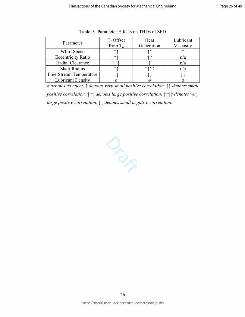
Subsequently, simulations were performed on more SFD configurations to observe the
effects of operating parameters, including: radial clearances, eccentricity ratios, whirl speeds,
lubricant densities, free-stream temperatures, and shaft radii. The observed output parameters are
the lubricant temperature offset from free-stream temperature, heat generation rate, and lubricant
viscosity. Changes to output parameters in response to increases in the operating parameters
were studied. The trends are listed and compared qualitatively in Table 9.
5. Conclusions
This work provided the detailed development of a CFD simulation model to study the
THD effects in SFDs. The equations incorporated into the hydrodynamic model, including the
boundary conditions were represented and the development of the SFD geometry and the
meshing were described. Subsequently, the CFD simulation parameters were provided and the
simulation results were represented.
The comparison between the CFD simulation model and the numerical THD model
proved that CFD simulations are powerful tools that could be used as a baseline to verify the
results of the numerical SFD models, where certain terms in the Navier-Stokes equations and
Energy Equation are neglected to improve the computational efficiency of the calculations.
Furthermore, it should be noted that CFD simulations can be incorporated to study more
complex SFD geometries.
Page 14 of 49
https://mc06.manuscriptcentral.com/tcsme-pubs
Transactions of the Canadian Society for Mechanical Engineering

Draft
15
References
ANSYS 2009. The Multiple Reference Frame Model. ANSYS, Inc. Available:
http://www.afs.enea.it/project/neptunius/docs/fluent/html/th/node33.htm [accessed 13 August
2018].
Chauhan, A., Singla, A., Panwar, N., and Jindal, P. 2014. CFD Based Thermo-Hydrodynamic
Analysis of Circular Journal Bearing. Int. Journal of Adv.Mech. Eng. 4(5): 475–82.
Cooper, S., 1963. Preliminary Investigation of Oil Films for the Control of Vibration. London,
UK: Institution of Mechanical Engineers.
Gertzos, K.P., Nikolakopoulos, P.G., and Papadopoulos, C.A. 2008. CFD Analysis of Journal
Bearing Hydrodynamic Lubrication by Bingham Lubricant. Trib. Int. 41(12). Elsevier: 1190–
1204. https://doi.org/10.1016/J.TRIBOINT.2008.03.002.
Hamzehlouia, S., and Behdinan, K. 2018. Thermohydrodynamic Modeling of Squeeze Film
Dampers in High-Speed Turbomachinery. SAE Int. Journal of Fuels and Lubricants. 11(2).
Lee, G.J., Kim, J., and Steen, T. 2017. Application of Computational Fluid Dynamics Simulation
to Squeeze Film Damper Analysis. Journal of Engineering for Gas Turbines and Power 139(10).
American Society of Mech. Eng.: 102501. https://doi.org/10.1115/1.4036511.
Narayana, B., Venkata, P., Ramaiah, and V. Krishnaiah, G., 2015. Analysis of Finite Length
Squeeze Film Damper Using Cfd. Int. Journal of Latest Trends in Eng. and Tech. 5(4).
Preston, F. W. 1932. The Temperature Coefficient of Viscosity and Its Relation to Some Other
Properties of Liquids and Glasses. Journal of the American Ceramic Society 15(7). Blackwell
Publishing Ltd: 365–365. https://doi.org/10.1111/j.1151-2916.1932.tb13945.x.
Roy, L. 2009. Thermo-Hydrodynamic Performance of Grooved Oil Journal Bearing. Trib. Int.
42(8). Elsevier: 1187–98. https://doi.org/10.1016/j.triboint.2009.04.001.
Szeri, A.Z. 2005. Fluid Film Lubrication: Theory and Design. Cambridge, UK: Cambridge
University
Tucker, P.G., and Keogh, P.s. 1995. A Generalized Computational Fluid Dynamics Approach for
Journal Bearing Performance Prediction. Proceedings of the Institution of Mech. Eng., Part J:
Page 15 of 49
https://mc06.manuscriptcentral.com/tcsme-pubs
Transactions of the Canadian Society for Mechanical Engineering

Draft
16
Journal of Eng. Trib. 209(2): 99–108. https://doi.org/10.1243/PIME_PROC_1995_209_412_02.
Vance, J.M. 1988. Rotordynamics of Turbomachinery. 9. John Wiley & Sons.
Zhang, Z.S., Yang, Y.S., Dai, X.D., and Xie, Y.B. 2013. Effects of Thermal Boundary
Conditions on Plain Journal Bearing Thermohydrodynamic Lubrication. Tribology Transactions
56(5): 759–70. https://doi.org/10.1080/10402004.2013.797531.
Page 16 of 49
https://mc06.manuscriptcentral.com/tcsme-pubs
Transactions of the Canadian Society for Mechanical Engineering

Draft
17
Tables
Nomenclature
Parameter Symbol Unit
Lubricant velocity components u, v, w m/s
Lubricant Density ρ kg/m3
Lubricant Heat Capacity Cp J/kg℃
Lubricant Pressure P Pa
Lubricant Viscosity µ Pa·s
Lubricant Viscosity at Free-Stream Temperature µ0 Pa·s
Lubricant Volume V m3
Lubricant, Shaft, and Bush Heat Conduction Coefficients Kf, Ks, Kb W/m℃
Lubricant, Shaft, and Bush Convection Coefficients Hf, Hs, Hb W/m2℃
Lubricant, Shaft, and Bush Temperatures Tf, Ts, Tb ℃
Free-Stream Temperature T0 ℃
Lubricant viscosity-temperature coefficient β
Air Thermal Conductivity Ka W/m℃
Gravitational Constant g m/s2
SFD Whirl Speed ω m/s
SFD Whirl Eccentricity
SFD Eccentricity Ratio
e
ε
m
SFD Radial Clearance C m
SFD Journal Length L m
Bush Inner Radius and Bush and Shaft Outer Radii Rbi, Rbo, Rso m
Page 17 of 49
https://mc06.manuscriptcentral.com/tcsme-pubs
Transactions of the Canadian Society for Mechanical Engineering

Draft
18
Table 1. Dimensions of SFD Model
Dimension Case A (mm) Case B (mm) Case C (mm)
SFD Width 32.5 32.5 32.5
Shaft Radius 50 50 20, 40, 60, 80, 100
SFD Radial
Clearance0.121
0.025, 0.05, 0.075,
0.1, 0.125, 0.150.1
Bushing
Radius66.875 80.025 - 80.15 50.1 - 130.1
Page 18 of 49
https://mc06.manuscriptcentral.com/tcsme-pubs
Transactions of the Canadian Society for Mechanical Engineering

Draft
19
Table 2. Mesh Properties of SFD Model
Mesh Property Value
Axial Divisions 80
Circumferential Divisions 72
Radial Divisions 50
Page 19 of 49
https://mc06.manuscriptcentral.com/tcsme-pubs
Transactions of the Canadian Society for Mechanical Engineering

Draft
20
Table 3. Material Properties of SFD
Property Shaft/Sleeve Fluid
Density (kg/m3) 2719 860
Cp (J/kg-K) 871 2000
Thermal Conductivity (W/m-K) 50 0.13
Viscosity (kg/m-s) --- 𝜇 = 0.0277𝑒 ―0.034(𝑇 ― 40)
Page 20 of 49
https://mc06.manuscriptcentral.com/tcsme-pubs
Transactions of the Canadian Society for Mechanical Engineering

Draft
21
Table 4. Operating Parameters
Operating Parameters Value
Whirl Eccentricity Ratio 0.1, 0.2, 0.3, 0.4, 0.5
Whirl Speed (rpm) 1000, 5000, 10000, 15000
Page 21 of 49
https://mc06.manuscriptcentral.com/tcsme-pubs
Transactions of the Canadian Society for Mechanical Engineering

Draft
22
Table 5. Boundary Conditions
Surface Boundary Condition
Shaft Axial Extremities and
Bushing Axial/Radial Extremities
Thermal boundary conditions as per
Equations (11) to (14). = =80ℎ𝑏 ℎ𝑠𝑤
𝑚2𝐾
Lubricant Film Axial ExtremityStationary Wall with no slip
No Heat Transfer
Film-Bush InterfaceStationary Wall with no slip
Heat Transfer as per Equation (7)
Film-Shaft Interface
Stationary Wall in separate MRF
moving as per Equations (17), (18)
Heat Transfer as per Equation (8)
Free-Stream Temperature 40℃
Page 22 of 49
https://mc06.manuscriptcentral.com/tcsme-pubs
Transactions of the Canadian Society for Mechanical Engineering

Draft
23
Table 6. Solution Methods
Parameter Method
Pressure-Velocity Coupling Scheme SIMPLE
Spatial Discretization: Gradient Least Squares Cell Based
Spatial Discretization: Pressure Second Order
Spatial Discretization: Momentum Second Order Upwind
Spatial Discretization: Energy Second Order Upwind
Page 23 of 49
https://mc06.manuscriptcentral.com/tcsme-pubs
Transactions of the Canadian Society for Mechanical Engineering

Draft
24
Table 7. Solution Control Values
Under-Relaxation Factors Value
Pressure 0.3
Density 1
Body Forces 1
Momentum 0.4
Energy 0.7
Page 24 of 49
https://mc06.manuscriptcentral.com/tcsme-pubs
Transactions of the Canadian Society for Mechanical Engineering

Draft
25
Table 8. Maximum Reynolds Number of each Section based on Input Parameters and Output
Values
Sectionω
(rpm)
Temperature
(℃)
Minimum µ
( )𝑷𝒂·𝒔
ρ
(kg/m3)
Radial Clearance
(mm)Re
4.1 15000 46.4 - 860 0.121 0.8884.2 15000 49.1 - 860 0.150 1.504.3 15000 44.1 - 860 0.100 0.5614.4 15000 - 0.00684 860 0.121 2.894.5 15000 42.9 - 1200 0.121 1.10
Page 25 of 49
https://mc06.manuscriptcentral.com/tcsme-pubs
Transactions of the Canadian Society for Mechanical Engineering
Draft
26
Table 9. Parameter Effects on THDs of SFD
Parameter Tf Offset from To
Heat Generation
Lubricant Viscosity
Whirl Speed ↑↑ ↑↑ ↑Eccentricity Ratio ↑↑ ↑↑ n/aRadial Clearance ↑↑↑ ↑↑↑ n/a
Shaft Radius ↑↑ ↑↑↑↑ n/aFree-Stream Temperature ↓↓ ↓↓ ↓↓
Lubricant Density ø ø øø denotes no effect, ↑ denotes very small positive correlation, ↑↑ denotes small
positive correlation, ↑↑↑ denotes large positive correlation, ↑↑↑↑ denotes very
large positive correlation, ↓↓ denotes small negative correlation.
Page 26 of 49
https://mc06.manuscriptcentral.com/tcsme-pubs
Transactions of the Canadian Society for Mechanical Engineering

Draft
27
Figure Captions
Fig. 1. Squeeze-Film Damper Schematic
Fig. 2. Schematic of Moving Reference Frame being used to move Water around an Impeller
(ANSYS 2009)
Fig. 3. Coordinate System Schematic for (a) Squeeze Film Damper and (b) Film Section of
Damper.
Fig. 4. Mesh of (a) the Shaft and Bush Geometry, and (b) Lubricant Film Geometry of the
modeled SFD. Mesh Density is reduced to 10% of simulation density in the Axial and Radial
Directions for Visual Clarity.
Fig. 5. Comparison of the Effect of Eccentricity Ratio on Mass-Averaged Temperature Inside the
Lubricant Film of the SFD T0=40℃ between Numerical and CFD Simulations,
(a) ω=1000 rpm, 5000 rpm, (b) ω=10000 rpm, 15000 rpm
Fig. 6. Comparison of the Effect of Eccentricity Ratio on Maximum Temperature Inside the
Lubricant Film of the SFD T0=40℃ between Numerical and CFD Simulations,
(a) ω=1000 rpm, 5000 rpm, (b) ω=10000 rpm, 15000 rpm
Fig. 7. Effect of Eccentricity Ratio on the Heat Generation inside the Lubricant Film of the SFD
at T0=40℃, (a) ω=1000 rpm, 5000 rpm, (b) ω=10000 rpm, 15000 rpm
Fig. 8. Static Temperature (℃) Distribution through Mid-Plane Cross-Section of Lubricant Film
for T0=40℃, ω=10000 rpm, (a) ε=0.1, (b) ε=0.5, Images Generated in ANSYS Fluent
Fig. 9. Effect of Radial Clearance on Mass-Averaged Temperature Inside the Lubricant Film of
the SFD at T0=40℃ and ε=0.5
Fig. 10. Effect of Radial Clearance on Maximum Temperature Inside the Lubricant Film of the
SFD at T0=40℃ and ε=0.5
Fig. 11. Effect of Radial Clearance on Heat Generation Inside the Lubricant Film of the SFD
during Steady-State Operation at T0=40℃ and ε=0.5
Page 27 of 49
https://mc06.manuscriptcentral.com/tcsme-pubs
Transactions of the Canadian Society for Mechanical Engineering

Draft
28
Fig. 12. Effect of Shaft Radius on Mass-Averaged Temperature Inside the Lubricant Film of the
SFD at T0=40℃ and ε=0.5
Fig. 13. Effect of Shaft Radius on Maximum Temperature Inside the Lubricant Film of the SFD
at T0=40℃ and ε=0.5
Fig. 14. Effect of Shaft Radius on Heat Generation Inside the Lubricant Film of the SFD during
Steady-State Operation at T0=40℃ and ε=0.5
Fig. 15. Effect of Free-Stream Temperature on Mass-Averaged Temperature Increase Inside the
Lubricant Film of the SFD at ε=0.5
Fig. 16. Effect of Free-Stream Temperature on Maximum Temperature Increase Inside the
Lubricant Film of the SFD at ε=0.5
Fig. 17. Effect of Free-Stream Temperature on Heat Generation Inside the Lubricant Film of the
SFD during Steady-State Operation at ε=0.5
Fig. 18. Effect of Free-Stream Temperature on Lubricant Viscosity Inside the Lubricant Film of
the SFD at ε=0.5 and ω=10000 rpm, ω=15000 rpm
Fig. 19. Effect of Lubricant Density on Mass-Averaged Temperature Inside the Lubricant Film
of the SFD at T0=40℃ and ε=0.5
Fig. 20. Effect of Lubricant Density on Maximum Temperature Inside the Lubricant Film of the
SFD at T0=40℃ and ε=0.5
Fig. 21. Effect of Lubricant Density on Heat Generation Inside the Lubricant Film of the SFD
during Steady-State Operation at T0=40℃ and ε=0.5
Page 28 of 49
https://mc06.manuscriptcentral.com/tcsme-pubs
Transactions of the Canadian Society for Mechanical Engineering

Draft
86x86mm (96 x 96 DPI)
Page 29 of 49
https://mc06.manuscriptcentral.com/tcsme-pubs
Transactions of the Canadian Society for Mechanical Engineering

Draft
100x89mm (96 x 96 DPI)
Page 30 of 49
https://mc06.manuscriptcentral.com/tcsme-pubs
Transactions of the Canadian Society for Mechanical Engineering

Draft
103x186mm (96 x 96 DPI)
Page 31 of 49
https://mc06.manuscriptcentral.com/tcsme-pubs
Transactions of the Canadian Society for Mechanical Engineering

Draft
152x219mm (96 x 96 DPI)
Page 32 of 49
https://mc06.manuscriptcentral.com/tcsme-pubs
Transactions of the Canadian Society for Mechanical Engineering

Draft
158x168mm (96 x 96 DPI)
Page 33 of 49
https://mc06.manuscriptcentral.com/tcsme-pubs
Transactions of the Canadian Society for Mechanical Engineering

Draft
155x171mm (96 x 96 DPI)
Page 34 of 49
https://mc06.manuscriptcentral.com/tcsme-pubs
Transactions of the Canadian Society for Mechanical Engineering

Draft
156x174mm (96 x 96 DPI)
Page 35 of 49
https://mc06.manuscriptcentral.com/tcsme-pubs
Transactions of the Canadian Society for Mechanical Engineering

Draft
177x191mm (96 x 96 DPI)
Page 36 of 49
https://mc06.manuscriptcentral.com/tcsme-pubs
Transactions of the Canadian Society for Mechanical Engineering

Draft
165x70mm (96 x 96 DPI)
Page 37 of 49
https://mc06.manuscriptcentral.com/tcsme-pubs
Transactions of the Canadian Society for Mechanical Engineering

Draft
165x71mm (96 x 96 DPI)
Page 38 of 49
https://mc06.manuscriptcentral.com/tcsme-pubs
Transactions of the Canadian Society for Mechanical Engineering

Draft
165x72mm (96 x 96 DPI)
Page 39 of 49
https://mc06.manuscriptcentral.com/tcsme-pubs
Transactions of the Canadian Society for Mechanical Engineering

Draft
165x68mm (96 x 96 DPI)
Page 40 of 49
https://mc06.manuscriptcentral.com/tcsme-pubs
Transactions of the Canadian Society for Mechanical Engineering

Draft
165x69mm (96 x 96 DPI)
Page 41 of 49
https://mc06.manuscriptcentral.com/tcsme-pubs
Transactions of the Canadian Society for Mechanical Engineering

Draft
165x70mm (96 x 96 DPI)
Page 42 of 49
https://mc06.manuscriptcentral.com/tcsme-pubs
Transactions of the Canadian Society for Mechanical Engineering

Draft
165x74mm (96 x 96 DPI)
Page 43 of 49
https://mc06.manuscriptcentral.com/tcsme-pubs
Transactions of the Canadian Society for Mechanical Engineering

Draft
165x74mm (96 x 96 DPI)
Page 44 of 49
https://mc06.manuscriptcentral.com/tcsme-pubs
Transactions of the Canadian Society for Mechanical Engineering

Draft
165x70mm (96 x 96 DPI)
Page 45 of 49
https://mc06.manuscriptcentral.com/tcsme-pubs
Transactions of the Canadian Society for Mechanical Engineering

Draft
165x74mm (96 x 96 DPI)
Page 46 of 49
https://mc06.manuscriptcentral.com/tcsme-pubs
Transactions of the Canadian Society for Mechanical Engineering

Draft
165x72mm (96 x 96 DPI)
Page 47 of 49
https://mc06.manuscriptcentral.com/tcsme-pubs
Transactions of the Canadian Society for Mechanical Engineering

Draft
165x73mm (96 x 96 DPI)
Page 48 of 49
https://mc06.manuscriptcentral.com/tcsme-pubs
Transactions of the Canadian Society for Mechanical Engineering

Draft
165x74mm (96 x 96 DPI)
Page 49 of 49
https://mc06.manuscriptcentral.com/tcsme-pubs
Transactions of the Canadian Society for Mechanical Engineering