application of battery energy storage systems for relief
TRANSCRIPT
energies
Article
Application of Battery Energy Storage Systems for Relief ofGeneration Curtailment in Terms of Transient Stability
Hyeongpil Bang 1 , Dwi Riana Aryani 2 and Hwachang Song 2,*
�����������������
Citation: Bang, H.; Aryani, D.R.;
Song, H. Application of Battery
Energy Storage Systems for Relief of
Generation Curtailment in Terms of
Transient Stability. Energies 2021, 14,
3898. https://doi.org/10.3390/
en14133898
Academic Editor: Carlos
Henggeler Antunes
Received: 13 May 2021
Accepted: 24 June 2021
Published: 29 June 2021
Publisher’s Note: MDPI stays neutral
with regard to jurisdictional claims in
published maps and institutional affil-
iations.
Copyright: © 2021 by the authors.
Licensee MDPI, Basel, Switzerland.
This article is an open access article
distributed under the terms and
conditions of the Creative Commons
Attribution (CC BY) license (https://
creativecommons.org/licenses/by/
4.0/).
1 Korea Electric Power Research Institute, Korea Electric Power Corporation, 105 Munji-ro, Yuseong-gu,Daejeon 34056, Korea; [email protected]
2 Department of Electrical and Information Engineering, Seoul National University of Science and Technology,232 Gongneung-ro, Nowon-gu, Seoul 01811, Korea; [email protected]
* Correspondence: [email protected]; Tel.: +82-2-970-6403
Abstract: Maintaining transient stability is crucial in power system operation. Transient stability ismainly affected by the generation amount of the study region, as well as the transmission topology.Several countermeasures can be taken for transient stability, but the usually used control means aregenerating unit tripping and generation curtailment. In terms of economic operation, one can saythat the solution of generating unit tripping is more beneficial. To maintain the transient stability ofthe east coast region in the Korean power system, applying generation curtailment in the normalstate is further needed, because the required tripping amount is too large for the case of only takinggenerator tripping, and this might cause a critical decrease in system frequency, possibly resulting inoperation of the first stage of under frequency relay (UFR). This paper presents the application ofbattery energy storage systems (BESSs) to relieve the generation curtailment, using the characteristicof fast response of BESS. Assuming that BESSs are installed in the candidate location in the studyregion, the adequate BESS action of absorbing the kinetic energy from those critical generators afterdisturbances can improve transient stability, and it can decrease the amount of generation curtailment.This paper includes the results of simulation studies to show the effectiveness of the BESS control forthe relief of generation curtailment.
Keywords: battery energy storage systems (BESSs); countermeasures; generation curtailment; stabil-ity improvement; transient stability
1. Introduction
In power system operation, maintaining transient stability is one of important factorsto secure the system subjected to a severe disturbance, which may lead to a large impact,such as the loss of synchronism of rotating machines [1]. Transient stability as one ofsubcategories of rotor angle stability is mainly affected by the generation level of the studyregion and the transmission topology [2]. The challenge in maintaining transient stabilitymight increase for future power systems as the total inertia in the system reduces due tothe high penetration of power electronic interfaced generators [3,4]. To improve transientstability, several countermeasures can be taken, including equipping new facilities in thesystem planning stage, but the usually used control means in the system operating stage aregenerating unit tripping and generation curtailment. Of them, tripping critical generatingunits is considered more economical because it is in the category of corrective actions thatcan be applied when the event actually happens during system operation.
If the generation level in the study region is critically high without enough transmis-sion capability after the critical event, such as in the east coast region of Korea, the requiredamount of generation tripping is so high and the action might cause a critical frequencydecrease, possibly resulting in operation of the first stage of under frequency relay (UFR).According to the Korean power system reliability criteria [5], if system operator noticesthe operation of UFR in the normal design contingent states, the countermeasures against
Energies 2021, 14, 3898. https://doi.org/10.3390/en14133898 https://www.mdpi.com/journal/energies

Energies 2021, 14, 3898 2 of 14
the UFR operation should be devised. In this situation, the other control mean, genera-tion curtailment, needs to be adopted to satisfy a certain rule with a limited generationtripping amount.
In most cases, relieving generation curtailment is desirable with other control means,because generation curtailment is a preventive measure applied in the normal state. There-fore, this paper proposes the application of the energy storage system (ESS) to relieve therequired generation curtailment. Several ESS applications for grid support including itsbenefits and challenges have been being studied and reviewed. In Reference [6], a batteryenergy storage system (BESS), with its fast response, contributes to the power systemby providing a better emergency control. BESS also offers several important benefits toindividual customer by gaining the flexibility of the power system, which further leads tocost efficiency. For grid support applications, adequate design of the inverter is requiredas in Reference [7]. In Reference [8], the application of BESS is identified into ten keyapplications for the entire power system chain from generation system, transmission anddistribution system, and customers. Multiple benefits of each key application are analyzedresulting in three applications with the highest value in terms of total cost resource, namelythe wholesale service with regulation, commercial and industrial power quality and reli-ability, and stationary and transportable systems for grid support and transmission anddistribution deferral. In some circumstances, a combination of two or more ESS applica-tions is required to produce total benefits that exceed total costs [9]. Furthermore, ESSapplication for modern power system is reviewed in References [10,11]; Reference [10]presents potential applications for wind power support, while Reference [11] identifies ESSissues and challenges for microgrid applications. There are some challenges in the policyaspects which may limit the true potential of BESS, particularly due to its multifunctionalcharacteristic so that ownership and operational rules among various stakeholders aredifficult to establish [8]. However, several significant changes in policy aspects have beenimplemented with the support of technological developments so that more benefits fromthe ESS can be obtained [12].
The ESS applications can be categorized into three groups, from the viewpoint of gridsupport type, such as energy, power and flexibility support services. For energy supportservice, ESS with large energy capacity is required as it is used for long charge/dischargedurations from some minutes to hours, and this kind of service is mainly for energytime shift. For power support service, the required capacity of energy storage is notas large as the one for energy support service, since the ESS is used for short periodof time; however, the ESS power output should be high. Flexibility support service isto provide additional flexibility to the system with high penetration rate of renewableenergy resources. Of them, network stability improvement by ESS is included in powersupport service. Pertaining to this ESS application, there were some works conducted inthe literature. In Reference [13], a feasibility study on transient stability improvement usingsuperconducting magnetic energy storages (SMES) was performed. In Reference [14], acontroller for damping improvement and voltage regulation using energy storage deviceswas proposed using the input–output feedback linearization method. In Reference [15],tube-based model predictive control method was employed to obtain power output signalsof SMES for transient stability improvement.
This paper presents a feasibility study on the application of battery energy storagesystems (BESSs) for the relief of generation curtailment caused by a severe disturbanceaffecting the transient stability of Korean power systems. In the study, a control model of theBESS was needed to obtain their impact on transient stability. To improve transient stability,the desirable behavior of BESS to absorb the kinetic energy of critical generators increasedduring disturbances, assuming that BESSs are equipped near the generators. There are twomethods that can be considered to implement the action, namely the frequency responseand the event-based control. The first strategy uses the frequency deviation as the input forthe droop control to determine the output power of BESS. The other is a type of specialprotection scheme such that the critical event activates the charging control of BESS with a

Energies 2021, 14, 3898 3 of 14
specified constant active power. The impact of both control strategies in terms of stabilityimprovement is compared, and the control parameter of each strategies is observed toobtain the most adequate setting. By taking the advantages of each strategy, this studyproposes the combination of the two control schemes, and this is called a hybrid controlstrategy, and the proper control parameters that have been observed previously are alsoapplied. Based on the simulation result, the hybrid control strategy proved to be able tooutperform the other two strategies. The impact of the proposed hybrid control-basedBESS is not only improving the transient stability but also enhancing the frequency stabilityof the system, which is another issue that requires generation curtailment. Moreover,the effectiveness of BESS using the proposed hybrid control to relieve the generationcurtailment is examined. It is obtained that the relief effect of the generation curtailmentcan be maximized when the BESS output is below 40 MW.
The rest of this paper is organized as follows. In Section 2, the application of BESSfor relief of generation curtailment is explained. The control strategy of BESS for relief ofgeneration curtailment is presented in Section 3. Simulation results and the analysis arediscussed in Section 4. Finally, several concluding remarks are provided in Section 5.
2. Generation Curtailment Relief with BESS
This chapter explains how the application of BESS for transient stability improvementcan relieve the generation curtailment. To obtain the insight transient stability, equal-areacriterion (EAC) with a single machine infinite bus (SMIB) equivalent model is usuallyconsidered [1,2]. The swing equation for the SMIB system with classical machine model isas follows:
2HωR
d2δ
dt2 = Pm − Pe(δ) = Pa (1)
where Pa is the accelerating power, H is the per unit inertia constant, and ωR is the rotorangular speed. The mechanical input of the generator (Pm) is assumed to be constant, whilethe electrical output (Pe) is a function of the rotor angle (δ). The electric output has differentvalues in every sub-process. Pe0(δ), Pe1(δ) and Pe2(δ) represent Pe at the pre-fault, duringfault and post-fault conditions, respectively.
Figure 1 depicts the concept of EAC in terms of transient stability. Before the oc-currence of the fault, mechanical input of the generator is equal to the electrical outputPe0(δ), and the synchronizing is maintained at the stable operating point (δ0). When a largedisturbance occurs in the external system, line impedance increases resulting in electricaloutput of the generator suddenly decreases from the initial balanced power by a certainamount depending on the severity of the fault. The power imbalance causes an increase inthe rotor angle from δ0 along the curve of Pe1(δ) with a positive value of Pa. During thefault, the inertial energy of the corresponding generator is accumulated by the angularacceleration of the rotor. If the accelerated energy, A1, in Figure 1, can be resolved by thedecelerated energy, A2, resulting from the restored power transmission after fault-clearing;and, hence, the synchronism is regained, and the system is said to be stable. The impedancebetween the generator and infinite bus will change again, leading to an increased levelof the electrical output to Pe1(δ). When A2 is less than A1 because of high loading or notenough transmission in the post-fault condition, adequate countermeasures need to bedevised to stabilize the system.

Energies 2021, 14, 3898 4 of 14Energies 2021, 14, x FOR PEER REVIEW 4 of 15
Figure 1. Illustration of equal area criterion (EAC).
To improve transient stability, several countermeasures can be considered. In the stage of operation and operational, applying generation curtailment and tripping critical generators are practically applicable. Generation curtailment is to reduce the generation level of the critical generators in the normal operation state, so it is regarded as a precau-tionary measure. If their generation costs are comparatively cheap, the action of curtail-ment might increase the total operation cost. Thus, the action of tripping critical genera-tors would be more economical because it is taken when the corresponding events actu-ally happen.
If the generation amount from the region of interest is too high considering transmis-sion capability after critical events, tripping action might not resolve all the security issues in terms of both transient and frequency stability. The east coast region of the Korean power system experiences this problem, because of the lack of transmission system con-sidering the generation level. The east coast region has two 345 kV routes and one 765 kV route to transfer the generation to the external region, and they are all double-circuited. When a two-circuit tower outage is applied to the 765 kV route, the scheme of generation tripping is required for transient stability and the tripping amount is determined for the peak load system. However, if the same amount of tripping is performed in the lightly loaded condition, the minimum point of the system frequency during transient might be lower than the pick-up value of the first stage of UFR setting. Therefore, a combined coun-termeasure with generation tripping and generation curtailment needs to be established.
This section focuses on the relief of generation curtailment with BESS application, assuming that the tripping scheme is given. Applying generation curtailment by reducing
basically reduces the accumulated kinetic energy of the critical generators, , during the fault. If the curtailed amount is enough to satisfy the EAC, the problem of stepping out can be resolved. As mentioned above, however, generation curtailment might degrade economical operation. Thus, reducing the amount of curtailment is desirable, and the in-stallation of BESS for stability improvement and curtailment reduction can be employed by using their fast responding characteristic of absorbing the kinetic energy of the critical generators after the fault. This action can increase the decelerated energy, , and, hence, it can secure transient stability.
An EAC illustration that considers generation curtailment and BESS charging action changes is presented in Figure 2. Applying these two countermeasures yield the new op-erating point, the accelerated area, and the decelerated area as with δ’0, ′ , and ′ , re-spectively. Besides, from Figure 2, one can notice that the generation curtailment can be exchanged with the charging operation of the BESS. When the capacity of BESS is limited, both actions can be included in the designed scheme for transient stability.
Figure 1. Illustration of equal area criterion (EAC).
To improve transient stability, several countermeasures can be considered. In the stageof operation and operational, applying generation curtailment and tripping critical genera-tors are practically applicable. Generation curtailment is to reduce the generation level ofthe critical generators in the normal operation state, so it is regarded as a precautionarymeasure. If their generation costs are comparatively cheap, the action of curtailment mightincrease the total operation cost. Thus, the action of tripping critical generators would bemore economical because it is taken when the corresponding events actually happen.
If the generation amount from the region of interest is too high considering transmis-sion capability after critical events, tripping action might not resolve all the security issuesin terms of both transient and frequency stability. The east coast region of the Korean powersystem experiences this problem, because of the lack of transmission system consideringthe generation level. The east coast region has two 345 kV routes and one 765 kV route totransfer the generation to the external region, and they are all double-circuited. When atwo-circuit tower outage is applied to the 765 kV route, the scheme of generation trippingis required for transient stability and the tripping amount is determined for the peak loadsystem. However, if the same amount of tripping is performed in the lightly loaded condi-tion, the minimum point of the system frequency during transient might be lower than thepick-up value of the first stage of UFR setting. Therefore, a combined countermeasure withgeneration tripping and generation curtailment needs to be established.
This section focuses on the relief of generation curtailment with BESS application,assuming that the tripping scheme is given. Applying generation curtailment by reducingPm basically reduces the accumulated kinetic energy of the critical generators, A1, duringthe fault. If the curtailed amount is enough to satisfy the EAC, the problem of steppingout can be resolved. As mentioned above, however, generation curtailment might degradeeconomical operation. Thus, reducing the amount of curtailment is desirable, and theinstallation of BESS for stability improvement and curtailment reduction can be employedby using their fast responding characteristic of absorbing the kinetic energy of the criticalgenerators after the fault. This action can increase the decelerated energy, A2, and, hence, itcan secure transient stability.
An EAC illustration that considers generation curtailment and BESS charging actionchanges is presented in Figure 2. Applying these two countermeasures yield the newoperating point, the accelerated area, and the decelerated area as with δ’0, A′1, and A′2,respectively. Besides, from Figure 2, one can notice that the generation curtailment can beexchanged with the charging operation of the BESS. When the capacity of BESS is limited,both actions can be included in the designed scheme for transient stability.

Energies 2021, 14, 3898 5 of 14Energies 2021, 14, x FOR PEER REVIEW 5 of 15
Figure 2. EAC with the generation curtailment and BESS.
By reviewing the EAC, one can notice that the relief of generation curtailment results the deceleration area becoming lower than the accelerated area, so that a certain action is needed to compensate the unfulfilled deceleration area for stability. The required addi-tional deceleration energy can be provided by the action of BESS charging, which operates after the action of fault clearing. The required amount of BESS power for transient stability would be proportional to the relieved capacity of the generation curtailment, which can be further expressed as follows. ∆ = , − , (2)
, = ( − − ) (3)
= ∆ (4)
where ∆ represents the relieved amount of the generation curtailment for the gen-erator, which is the difference between the generation curtailment before and after apply-ing the BESS strategy ( , and , ). It is obvious that the effectiveness of the BESS action is slightly less than that of generation curtailment because it is a corrective measure and there is an electrical distance between the generator and BESS. As in (4), is the ratio of the possible relief of generation curtailment to the power of BESS.
3. Control Strategy of BESS for Relief of Generation Curtailment This section depicts control strategies of BESS that can be adopted to relief the
amount of curtailing generation by absorbing the excessive kinetic energy of the critical generators during disturbances.
3.1. Transient Stability Problem in the East Coast Region in the Korean Power System The east coast region in the Korean power system poses a problem of transient sta-
bility. Figure 3 illustrates the structure of the region. As in Figure 3, there are three inter-face routes between the east coast region and the external system. The routes are all two-circuited; routes #1 and #2 are 345 kV, and route #3 is 765 kV. Each line in route #1 and route #2 has rating of 2173 MVA, while in route #3 each line rating is 7290 MVA. The critical fault that might cause transient instability in the east coast region is a tower outage on route #3 that results in a severe reduction in transfer capability to the external system, and the transfer capability cannot cover the fault current. Thus, after tripping the faulted lines, the kinetic energy and rotor angles of those generations in the region are dramati-
Figure 2. EAC with the generation curtailment and BESS.
By reviewing the EAC, one can notice that the relief of generation curtailment resultsthe deceleration area becoming lower than the accelerated area, so that a certain action isneeded to compensate the unfulfilled deceleration area for stability. The required additionaldeceleration energy can be provided by the action of BESS charging, which operates afterthe action of fault clearing. The required amount of BESS power for transient stabilitywould be proportional to the relieved capacity of the generation curtailment, which can befurther expressed as follows.
∆Pcurt = Pcurt,0 − Pcurt,BESS (2)
Pcurt,k =∫ δn
δ0
(Pm − Pe − PBESS) dδ (3)
Re f f =∆Pcurt
PBESS(4)
where ∆Pcurt represents the relieved amount of the generation curtailment for the generator,which is the difference between the generation curtailment before and after applying theBESS strategy (Pcurt,0 and Pcurt,BESS). It is obvious that the effectiveness of the BESS actionis slightly less than that of generation curtailment because it is a corrective measure andthere is an electrical distance between the generator and BESS. As in (4), Re f f is the ratio ofthe possible relief of generation curtailment to the power of BESS.
3. Control Strategy of BESS for Relief of Generation Curtailment
This section depicts control strategies of BESS that can be adopted to relief the amountof curtailing generation by absorbing the excessive kinetic energy of the critical generatorsduring disturbances.
3.1. Transient Stability Problem in the East Coast Region in the Korean Power System
The east coast region in the Korean power system poses a problem of transient stability.Figure 3 illustrates the structure of the region. As in Figure 3, there are three interface routesbetween the east coast region and the external system. The routes are all two-circuited;routes #1 and #2 are 345 kV, and route #3 is 765 kV. Each line in route #1 and route #2has rating of 2173 MVA, while in route #3 each line rating is 7290 MVA. The critical faultthat might cause transient instability in the east coast region is a tower outage on route#3 that results in a severe reduction in transfer capability to the external system, and thetransfer capability cannot cover the fault current. Thus, after tripping the faulted lines,the kinetic energy and rotor angles of those generations in the region are dramaticallyincreased without taking any control actions for transient stability. The action of generationtripping for transient stability is realized by a Special Protection Scheme (SPS). Thus, itapplies not only at the peak load level, but also at the lightly load level in the event of the

Energies 2021, 14, 3898 6 of 14
corresponding fault. When the amount of generation tripping is applied to the system with60% and 70% load level, the system frequency might fall below the first pickup level ofUFR operation in the system. This kind of load interruption, however, is prohibited by theKorean power system reliability criteria [5], so if the operation of UFR might happen inthe situation, another countermeasure should be devised, considering both transient andfrequency stability.
Energies 2021, 14, x FOR PEER REVIEW 6 of 15
cally increased without taking any control actions for transient stability. The action of gen-eration tripping for transient stability is realized by a Special Protection Scheme (SPS). Thus, it applies not only at the peak load level, but also at the lightly load level in the event of the corresponding fault. When the amount of generation tripping is applied to the sys-tem with 60% and 70% load level, the system frequency might fall below the first pickup level of UFR operation in the system. This kind of load interruption, however, is prohib-ited by the Korean power system reliability criteria [5], so if the operation of UFR might happen in the situation, another countermeasure should be devised, considering both transient and frequency stability.
Figure 3. East coast region in the Korean power system.
Then the tripping amount needs to be reduced to get the minimum transient fre-quency increased, possibly less than the pickup level, and for this purpose, generation curtailment is adopted in the normal state. The units for generation tripping are nuclear power plants, but those for generation curtailment are coal-fired. The reason is that, in the regulation, nuclear power plants should be operated with a non-governor operation. Thus, the action of curtailing more generation is needed for transient stability with the reduced generation tripping. Then the minimum transient frequency gets increased, which is higher than the UFR pickup level after the corresponding contingency in lightly loaded conditions.
3.2. Hybrid Control Strategy for BESS Application This paper adopts a hybrid control strategy for BESS application to relieve the
amount of curtailing generation. As in Figure 3, when the event of the 765 kV interface fault happens in the east coast region, kinetic energy of the generators in the region gets increased because of the limited transfer capability of the other 345 kV interface routes. It is obvious that, in the situation, bus frequencies in the region also get increased before the required control actions are taken. Thus, a frequency-response-based control strategy can be employed for BESS. From the viewpoint of transient stability improvement, it is desir-able to operate the control strategy as soon as the event happens. As another BESS control strategy, therefore, a method based on special protection scheme can be established. The first one is similar to frequency regulation, which determines the charging amount by us-ing the frequency deviation. The other one is one type of SPS. When the predefined outage happens in the system, the activation signal of charging control is sent to BESS.
Figure 4 illustrates the hybrid control strategy, combining the two strategies for the BESS application to stability improvement proposed in this paper. From Figure 4, one can notice that the primary control strategy is the event-based constant charging action where the control strategy is presented in the control block of fixed charge operation. When ap-plying the frequency-response-based control strategy shown in the frequency response operation control block, there exists a time-delay to capture bus frequency values at BESS locations. The time-delay comes from using a moving average to determine bus frequency as well as the communication time-delay between power conditioning systems (PCSs) and power management systems (PMSs) of BESS [16]. Then the total time delay is around 300
ESSExternal SystemGeneration Curtailment
ESS Control
East Coast Region
SPS Trip signal
Route #1Route #2
Route #3
Figure 3. East coast region in the Korean power system.
Then the tripping amount needs to be reduced to get the minimum transient frequencyincreased, possibly less than the pickup level, and for this purpose, generation curtailmentis adopted in the normal state. The units for generation tripping are nuclear power plants,but those for generation curtailment are coal-fired. The reason is that, in the regulation,nuclear power plants should be operated with a non-governor operation. Thus, the actionof curtailing more generation is needed for transient stability with the reduced generationtripping. Then the minimum transient frequency gets increased, which is higher than theUFR pickup level after the corresponding contingency in lightly loaded conditions.
3.2. Hybrid Control Strategy for BESS Application
This paper adopts a hybrid control strategy for BESS application to relieve the amountof curtailing generation. As in Figure 3, when the event of the 765 kV interface fault happensin the east coast region, kinetic energy of the generators in the region gets increased becauseof the limited transfer capability of the other 345 kV interface routes. It is obvious that, inthe situation, bus frequencies in the region also get increased before the required controlactions are taken. Thus, a frequency-response-based control strategy can be employed forBESS. From the viewpoint of transient stability improvement, it is desirable to operate thecontrol strategy as soon as the event happens. As another BESS control strategy, therefore,a method based on special protection scheme can be established. The first one is similarto frequency regulation, which determines the charging amount by using the frequencydeviation. The other one is one type of SPS. When the predefined outage happens in thesystem, the activation signal of charging control is sent to BESS.
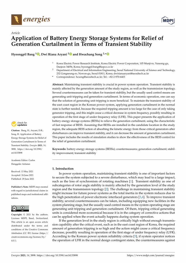
Figure 4 illustrates the hybrid control strategy, combining the two strategies for theBESS application to stability improvement proposed in this paper. From Figure 4, onecan notice that the primary control strategy is the event-based constant charging actionwhere the control strategy is presented in the control block of fixed charge operation. Whenapplying the frequency-response-based control strategy shown in the frequency responseoperation control block, there exists a time-delay to capture bus frequency values at BESSlocations. The time-delay comes from using a moving average to determine bus frequencyas well as the communication time-delay between power conditioning systems (PCSs) andpower management systems (PMSs) of BESS [16]. Then the total time delay is around300 ms. For transient stability improvement, the fast charging action of BESS is desirableto absorb the excessive kinetic energy of the region and hence to ensure transient stabilityof the east coast region. Thus, the event-based constant charging control is chosen as theprimary strategy.
Energies 2021, 14, 3898 7 of 14
Energies 2021, 14, x FOR PEER REVIEW 7 of 15
ms. For transient stability improvement, the fast charging action of BESS is desirable to absorb the excessive kinetic energy of the region and hence to ensure transient stability of the east coast region. Thus, the event-based constant charging control is chosen as the primary strategy.
Figure 4. The proposed BESS hybrid control block.
The first stage of the scheme using the event-based constant charging is to ensure transient stability with the defined power output of the BESS within a short period of time after fault. In the simulation study, a 1 s power injection is adequate. Then the BESS con-trol is switched to the second stage for frequency regulation support, using a frequency-response operation scheme. As in Figure 3, when the 765 kV interface fault occurs, the action of generator tripping is activated with SPS, and the tripping amount about 2.5 GW. This action might cause a deep frequency drop, especially in the lightly loaded condition. The BESS action for frequency regulation support can relieve the amount of generation curtailment by the frequency drop after the event in the east coast. The impact of the action on the amount of relief of generation curtailment is stated in the next chapter.
3.3. Procedure to Evaluate the BESS Impact on Relief of Generation Curtailment In the cases where transient stability is not secured by applying the generation trip-
ping amount, additional countermeasures are further needed, such as generation curtail-ment in the study region. The generation curtailment can be replaced by the power injec-tion of BESS, even though it is taken after the event actually happens because of its fast responding capability. To examine the hybrid control action of BESS on transient stability, the procedure performed in the study is given below, in Figure 5.
Figure 4. The proposed BESS hybrid control block.
The first stage of the scheme using the event-based constant charging is to ensuretransient stability with the defined power output of the BESS within a short period oftime after fault. In the simulation study, a 1 s power injection is adequate. Then the BESScontrol is switched to the second stage for frequency regulation support, using a frequency-response operation scheme. As in Figure 3, when the 765 kV interface fault occurs, theaction of generator tripping is activated with SPS, and the tripping amount about 2.5 GW.This action might cause a deep frequency drop, especially in the lightly loaded condition.The BESS action for frequency regulation support can relieve the amount of generationcurtailment by the frequency drop after the event in the east coast. The impact of the actionon the amount of relief of generation curtailment is stated in the next chapter.
3.3. Procedure to Evaluate the BESS Impact on Relief of Generation Curtailment
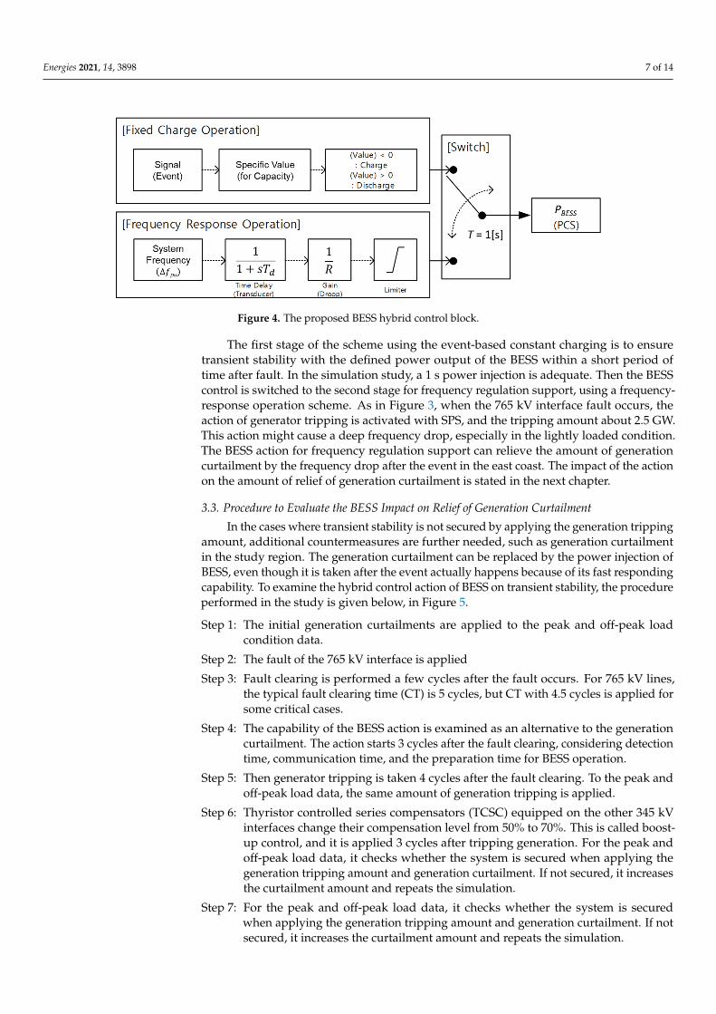
In the cases where transient stability is not secured by applying the generation trippingamount, additional countermeasures are further needed, such as generation curtailmentin the study region. The generation curtailment can be replaced by the power injection ofBESS, even though it is taken after the event actually happens because of its fast respondingcapability. To examine the hybrid control action of BESS on transient stability, the procedureperformed in the study is given below, in Figure 5.
Step 1: The initial generation curtailments are applied to the peak and off-peak loadcondition data.
Step 2: The fault of the 765 kV interface is applied
Step 3: Fault clearing is performed a few cycles after the fault occurs. For 765 kV lines,the typical fault clearing time (CT) is 5 cycles, but CT with 4.5 cycles is applied forsome critical cases.
Step 4: The capability of the BESS action is examined as an alternative to the generationcurtailment. The action starts 3 cycles after the fault clearing, considering detectiontime, communication time, and the preparation time for BESS operation.
Step 5: Then generator tripping is taken 4 cycles after the fault clearing. To the peak andoff-peak load data, the same amount of generation tripping is applied.
Step 6: Thyristor controlled series compensators (TCSC) equipped on the other 345 kVinterfaces change their compensation level from 50% to 70%. This is called boost-up control, and it is applied 3 cycles after tripping generation. For the peak andoff-peak load data, it checks whether the system is secured when applying thegeneration tripping amount and generation curtailment. If not secured, it increasesthe curtailment amount and repeats the simulation.
Step 7: For the peak and off-peak load data, it checks whether the system is securedwhen applying the generation tripping amount and generation curtailment. If notsecured, it increases the curtailment amount and repeats the simulation.
Energies 2021, 14, 3898 8 of 14
Step 8: If transiently secured, it checks whether the minimum transient frequency in theoff-peak condition is over the pick-up value of UFR setting considering the margin.If there is no violation of the criteria, it outputs the results and ends; otherwise,it increases the tripping amount for the peak and off-peak load data and repeatsthe simulation.Energies 2021, 14, x FOR PEER REVIEW 8 of 15
Figure 5. Evaluation procedure of generation curtailment relief using BESS.
Step 1: The initial generation curtailments are applied to the peak and off-peak load con-dition data.
Step 2: The fault of the 765 kV interface is applied Step 3: Fault clearing is performed a few cycles after the fault occurs. For 765 kV lines, the
typical fault clearing time (CT) is 5 cycles, but CT with 4.5 cycles is applied for some critical cases.
Figure 5. Evaluation procedure of generation curtailment relief using BESS.

Energies 2021, 14, 3898 9 of 14
4. Study Results
In this paper, a dynamic time simulation study was carried out by using PSS/E [17]to examine the effect of BESS on transient stability after a large disturbance on the 765 kVinterface for the east coast. For the simulation, the system models were the modifiedKEPCO 2019 network data with 100% and 60% load level by adding BESS located near thegeneration complex in east coast region. For BESS, CBEST model was adopted in PSS/Efor the dynamic model of BESS, as shown in Figure 6. Output of BESS control strategy(PBESS), as in Figure 4, is used as the input signal of CBEST-based BESS dynamic model.Furthermore, the hybrid control block for BESS, as detailed in Figure 5, was implementedbased on the imbedded Python in PSS/E.
Energies 2021, 14, x FOR PEER REVIEW 9 of 15
Step 4: The capability of the BESS action is examined as an alternative to the generation curtailment. The action starts 3 cycles after the fault clearing, considering detection time, communication time, and the preparation time for BESS operation.
Step5: Then generator tripping is taken 4 cycles after the fault clearing. To the peak and off-peak load data, the same amount of generation tripping is applied.
Step6: Thyristor controlled series compensators (TCSC) equipped on the other 345 kV in-terfaces change their compensation level from 50% to 70%. This is called boost-up control, and it is applied 3 cycles after tripping generation. For the peak and off-peak load data, it checks whether the system is secured when applying the gener-ation tripping amount and generation curtailment. If not secured, it increases the curtailment amount and repeats the simulation.
Step7: For the peak and off-peak load data, it checks whether the system is secured when applying the generation tripping amount and generation curtailment. If not se-cured, it increases the curtailment amount and repeats the simulation.
Step8: If transiently secured, it checks whether the minimum transient frequency in the off-peak condition is over the pick-up value of UFR setting considering the margin. If there is no violation of the criteria, it outputs the results and ends; otherwise, it increases the tripping amount for the peak and off-peak load data and repeats the simulation.
4. Study Results In this paper, a dynamic time simulation study was carried out by using PSS/E [17]
to examine the effect of BESS on transient stability after a large disturbance on the 765 kV interface for the east coast. For the simulation, the system models were the modified KEPCO 2019 network data with 100% and 60% load level by adding BESS located near the generation complex in east coast region. For BESS, CBEST model was adopted in PSS/E for the dynamic model of BESS, as shown in Figure 6. Output of BESS control strategy ( ), as in Figure 4, is used as the input signal of CBEST-based BESS dynamic model. Furthermore, the hybrid control block for BESS, as detailed in Figure 5, was implemented based on the imbedded Python in PSS/E.
Figure 6. CBEST-based BESS dynamic model.
4.1. Application of Conventional Countermeasures for Transient Stability Pertaining to transient stability after a large disturbance, as mentioned in the previ-
ous section, generation tripping and curtailment are main countermeasures usually taken in system operation. Of them generation tripping is considered as more economical, but its effect on system frequency should be examined. Figure 7 shows the system frequency curves when the 3.5 GW and 2.5 GW generation tripping is applied to a lightly loaded system. To stabilize the transient stability, 2.5 GW generation tripping needs to be com-bined with 1.369 GW generation curtailment.
Figure 6. CBEST-based BESS dynamic model.
4.1. Application of Conventional Countermeasures for Transient Stability
Pertaining to transient stability after a large disturbance, as mentioned in the previoussection, generation tripping and curtailment are main countermeasures usually taken insystem operation. Of them generation tripping is considered as more economical, but itseffect on system frequency should be examined. Figure 7 shows the system frequencycurves when the 3.5 GW and 2.5 GW generation tripping is applied to a lightly loadedsystem. To stabilize the transient stability, 2.5 GW generation tripping needs to be combinedwith 1.369 GW generation curtailment.
Energies 2021, 14, x FOR PEER REVIEW 10 of 15
Figure 7. System frequency curves with the 3.5 and 2.5 GW generation tripping (60% load level).
From Figure 7, one can notice that the system frequency with 2.5 GW generation trip-ping is above the pickup frequency level and hence that the event does not cause the UFR operation. The pickup frequency level of the 1st stage of UFR in the system set to 59.0 Hz, but in the simulation, the margin of 0.2 Hz is adopted as in Korean power system reliabil-ity criteria [5]. Thus, the simulation of this study takes tripping generation with 2.5 GW in the east coast region after the occurrence of a fault on the 765 kV interface to the east coast region, as illustrated in Figure 3. The generation tripping amount indeed affects the re-quired amount of generation curtailment.
Figure 8 shows the result of transient stability simulation for those cases with adjust-ing fault clearing time when applying the conventional countermeasures. Basically, fault clearing time (CT) for 765 kV lines is five cycles after the event, but CT of 4.5 cycles was also applied to unstable cases. By only applying the generation tripping of 2.5 GW, the system was unstable in first-swing. Then, the additional countermeasure with generation curtailment was taken, and 200 MW and 250 MW were examined for the amount of cur-tailing in the simulation. When using CT of five cycles for the event, critical generators in the east coast region experienced a stepping out with 2.5 GW tripping and 200 MW cur-tailment. However, when CT was changed to 4.5 cycles, transient stability was secured. In the case of taking 2.5 GW tripping and 250 MW curtailment, the system was transiently stable.
If one or more BESSs are installed in the region, then the hybrid control action of BESS can absorb the excessive kinetic energy of the critical generators and hence can sta-bilize the system for the case with 200 MW curtailment; in other words, it can replace the amount of generation curtailment for the stable case with 250 MW curtailment even though the control signal is sent to BESS throughout a certain SPS after the event happens. Then, the issue is the ratio of BESS injection capacity to the relieved amount of generation curtailment. Section 4.3 provides the simulation results on the issue.
Figure 8. Examination of transient stability with different control measures.
Figure 7. System frequency curves with the 3.5 and 2.5 GW generation tripping (60% load level).
From Figure 7, one can notice that the system frequency with 2.5 GW generationtripping is above the pickup frequency level and hence that the event does not cause theUFR operation. The pickup frequency level of the 1st stage of UFR in the system set to59.0 Hz, but in the simulation, the margin of 0.2 Hz is adopted as in Korean power systemreliability criteria [5]. Thus, the simulation of this study takes tripping generation with2.5 GW in the east coast region after the occurrence of a fault on the 765 kV interface to theeast coast region, as illustrated in Figure 3. The generation tripping amount indeed affectsthe required amount of generation curtailment.
Figure 8 shows the result of transient stability simulation for those cases with adjust-ing fault clearing time when applying the conventional countermeasures. Basically, fault

Energies 2021, 14, 3898 10 of 14
clearing time (CT) for 765 kV lines is five cycles after the event, but CT of 4.5 cycles was alsoapplied to unstable cases. By only applying the generation tripping of 2.5 GW, the systemwas unstable in first-swing. Then, the additional countermeasure with generation curtail-ment was taken, and 200 MW and 250 MW were examined for the amount of curtailing inthe simulation. When using CT of five cycles for the event, critical generators in the eastcoast region experienced a stepping out with 2.5 GW tripping and 200 MW curtailment.However, when CT was changed to 4.5 cycles, transient stability was secured. In the caseof taking 2.5 GW tripping and 250 MW curtailment, the system was transiently stable.
Energies 2021, 14, x FOR PEER REVIEW 10 of 15
Figure 7. System frequency curves with the 3.5 and 2.5 GW generation tripping (60% load level).
From Figure 7, one can notice that the system frequency with 2.5 GW generation trip-ping is above the pickup frequency level and hence that the event does not cause the UFR operation. The pickup frequency level of the 1st stage of UFR in the system set to 59.0 Hz, but in the simulation, the margin of 0.2 Hz is adopted as in Korean power system reliabil-ity criteria [5]. Thus, the simulation of this study takes tripping generation with 2.5 GW in the east coast region after the occurrence of a fault on the 765 kV interface to the east coast region, as illustrated in Figure 3. The generation tripping amount indeed affects the re-quired amount of generation curtailment.
Figure 8 shows the result of transient stability simulation for those cases with adjust-ing fault clearing time when applying the conventional countermeasures. Basically, fault clearing time (CT) for 765 kV lines is five cycles after the event, but CT of 4.5 cycles was also applied to unstable cases. By only applying the generation tripping of 2.5 GW, the system was unstable in first-swing. Then, the additional countermeasure with generation curtailment was taken, and 200 MW and 250 MW were examined for the amount of cur-tailing in the simulation. When using CT of five cycles for the event, critical generators in the east coast region experienced a stepping out with 2.5 GW tripping and 200 MW cur-tailment. However, when CT was changed to 4.5 cycles, transient stability was secured. In the case of taking 2.5 GW tripping and 250 MW curtailment, the system was transiently stable.
If one or more BESSs are installed in the region, then the hybrid control action of BESS can absorb the excessive kinetic energy of the critical generators and hence can sta-bilize the system for the case with 200 MW curtailment; in other words, it can replace the amount of generation curtailment for the stable case with 250 MW curtailment even though the control signal is sent to BESS throughout a certain SPS after the event happens. Then, the issue is the ratio of BESS injection capacity to the relieved amount of generation curtailment. Section 4.3 provides the simulation results on the issue.
Figure 8. Examination of transient stability with different control measures. Figure 8. Examination of transient stability with different control measures.
If one or more BESSs are installed in the region, then the hybrid control action of BESScan absorb the excessive kinetic energy of the critical generators and hence can stabilizethe system for the case with 200 MW curtailment; in other words, it can replace the amountof generation curtailment for the stable case with 250 MW curtailment even though thecontrol signal is sent to BESS throughout a certain SPS after the event happens. Then, theissue is the ratio of BESS injection capacity to the relieved amount of generation curtailment.Section 4.3 provides the simulation results on the issue.
4.2. Impact of BESS Control Strategies
In the study, several control strategies were examined to determine the adequatecontrol strategy for stability enhancement with BESS to replace the generation curtailment.This subsection describes the study results on that issue. In the study, the examined controlstrategies for BESS were modeled with Python imbedded in PSS/E, and the signals weregiven to the output of the active power part of CBEST model.
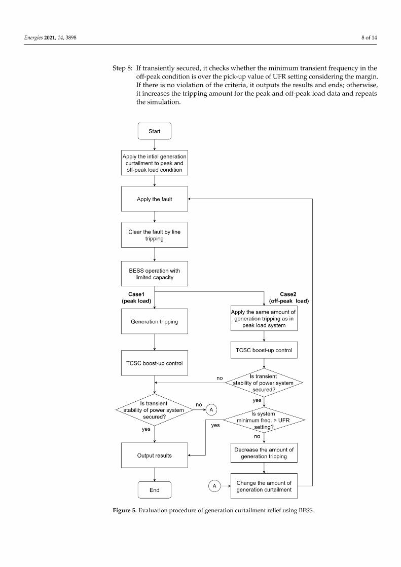
The strategies examined in the study were (i) constant power charging, (ii) frequencyresponsive and (iii) hybrid ones. From the time when the BESS power injection commandis delivered, numerical integration is performed by the imbedded Python according to eachcorresponding control block in the model, and the integration time step is 0.5 cycles for theBESS simulation. It is assumed that the input for frequency responsive control uses thebus frequency in which the BESS is installed. For all the strategies, the BESS capacity wasassumed to be 160 MW, which corresponds to the minimum required capacity for systemstabilization. Figure 9 shows the results of applying the constant charging strategy.
In this simulation, the effect of the ramp-rate to reach the maximum output of theBESS was examined. The ramp-rates were varied from one cycle to four cycles. From thesimulation result shown in Figure 9, one can notice that system stability could be securedwhen the ramp-rate to reach 160 MW for the BESS was one or two cycles. However, if theramp-rate period time was three or four cycles, the system might be unstable, because theaccelerated energy of the critical generators during the fault was not absorbed by the BESSwithin the required time delay.
Energies 2021, 14, 3898 11 of 14
Energies 2021, 14, x FOR PEER REVIEW 11 of 15
4.2. Impact of BESS Control Strategies In the study, several control strategies were examined to determine the adequate con-
trol strategy for stability enhancement with BESS to replace the generation curtailment. This subsection describes the study results on that issue. In the study, the examined con-trol strategies for BESS were modeled with Python imbedded in PSS/E, and the signals were given to the output of the active power part of CBEST model.
The strategies examined in the study were (i) constant power charging, (ii) frequency responsive and (iii) hybrid ones. From the time when the BESS power injection command is delivered, numerical integration is performed by the imbedded Python according to each corresponding control block in the model, and the integration time step is 0.5 cycles for the BESS simulation. It is assumed that the input for frequency responsive control uses the bus frequency in which the BESS is installed. For all the strategies, the BESS capacity was assumed to be 160 MW, which corresponds to the minimum required capacity for system stabilization. Figure 9 shows the results of applying the constant charging strategy.
(a) Bus frequency (b) BESS active power output
Figure 9. Performance of the constant charging strategy with different ramp-rates.
In this simulation, the effect of the ramp-rate to reach the maximum output of the BESS was examined. The ramp-rates were varied from one cycle to four cycles. From the simulation result shown in Figure 9, one can notice that system stability could be secured when the ramp-rate to reach 160 MW for the BESS was one or two cycles. However, if the ramp-rate period time was three or four cycles, the system might be unstable, because the accelerated energy of the critical generators during the fault was not absorbed by the BESS within the required time delay.
The second strategy examined in the simulation is frequency responsive one, and it is similar to droop control for primary frequency regulation (PFR) [18]. The difference of the strategy from PFR is that it includes the block for checking the initial rate of change of frequency (ROCOF), and it activates the frequency responsive action by the BESS if the absolute value of ROCOF is greater than the threshold value. The threshold value is usu-ally set to the one the system responds to when a generating unit with 500 MW is tripped. In this simulation, the event includes the tripping with a large amount generation for sta-bilization, so the impact of droop gain change was evaluated. Figure 10 presents the com-parison of BESS transient stability effect when the droop gain is adjusted from 100 to 400 for a 160 MW-BESS. That is, it tried to verify what the required droop gain for transient stability. The required droop gain for stability is 300. The droop gain can be defined as a specific value that affects the relation between active power and frequency change rate of the BESS.
Figure 9. Performance of the constant charging strategy with different ramp-rates.
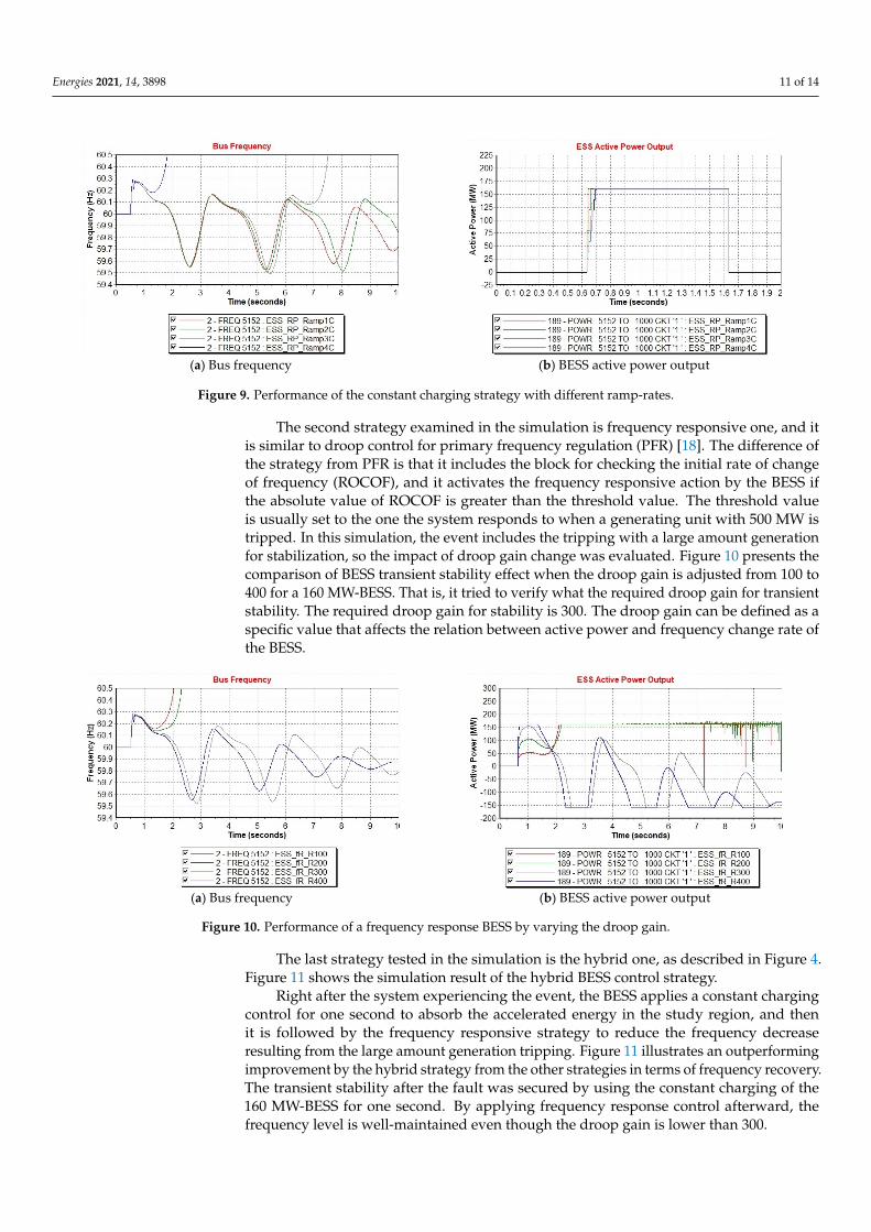
The second strategy examined in the simulation is frequency responsive one, and itis similar to droop control for primary frequency regulation (PFR) [18]. The difference ofthe strategy from PFR is that it includes the block for checking the initial rate of changeof frequency (ROCOF), and it activates the frequency responsive action by the BESS ifthe absolute value of ROCOF is greater than the threshold value. The threshold valueis usually set to the one the system responds to when a generating unit with 500 MW istripped. In this simulation, the event includes the tripping with a large amount generationfor stabilization, so the impact of droop gain change was evaluated. Figure 10 presents thecomparison of BESS transient stability effect when the droop gain is adjusted from 100 to400 for a 160 MW-BESS. That is, it tried to verify what the required droop gain for transientstability. The required droop gain for stability is 300. The droop gain can be defined as aspecific value that affects the relation between active power and frequency change rate ofthe BESS.
Energies 2021, 14, x FOR PEER REVIEW 12 of 15
(a) Bus frequency (b) BESS active power output
Figure 10. Performance of a frequency response BESS by varying the droop gain.
The last strategy tested in the simulation is the hybrid one, as described in Figure 4. Figure 11 shows the simulation result of the hybrid BESS control strategy.
(a) Bus frequency (b) BESS active power output
Figure 11. Performance of a hybrid control BESS with different frequency response droop gain.
Right after the system experiencing the event, the BESS applies a constant charging control for one second to absorb the accelerated energy in the study region, and then it is followed by the frequency responsive strategy to reduce the frequency decrease resulting from the large amount generation tripping. Figure 11 illustrates an outperforming im-provement by the hybrid strategy from the other strategies in terms of frequency recovery. The transient stability after the fault was secured by using the constant charging of the 160 MW-BESS for one second. By applying frequency response control afterward, the fre-quency level is well-maintained even though the droop gain is lower than 300.
4.3. Relief Effect of Generation Curtailment by the Large-Capacity BESS Application The sum of the rated power of those generators for curtailment operation in the east
coast region is 2 GW (1 GW per unit), which is near the power plant for tripping. If the curtailment to the corresponding generators is not enough in the normal state, the re-quired amount of generator tripping is increased for stabilization after the event, and, hence, it might decrease the minimum transient frequency in the lightly loaded system. With the fixed amount of tripping possible, to relieve the curtailment amount in the nor-mal state, the BESS capacity needs to be increased because it can replace the curtailment. With such a concept, the main question is what the ratio of the possible relief of generation curtailment to the BESS capacity is, satisfying stability.
Figure 10. Performance of a frequency response BESS by varying the droop gain.
The last strategy tested in the simulation is the hybrid one, as described in Figure 4.Figure 11 shows the simulation result of the hybrid BESS control strategy.
Right after the system experiencing the event, the BESS applies a constant chargingcontrol for one second to absorb the accelerated energy in the study region, and thenit is followed by the frequency responsive strategy to reduce the frequency decreaseresulting from the large amount generation tripping. Figure 11 illustrates an outperformingimprovement by the hybrid strategy from the other strategies in terms of frequency recovery.The transient stability after the fault was secured by using the constant charging of the160 MW-BESS for one second. By applying frequency response control afterward, thefrequency level is well-maintained even though the droop gain is lower than 300.

Energies 2021, 14, 3898 12 of 14
Energies 2021, 14, x FOR PEER REVIEW 12 of 15
(a) Bus frequency (b) BESS active power output
Figure 10. Performance of a frequency response BESS by varying the droop gain.
The last strategy tested in the simulation is the hybrid one, as described in Figure 4. Figure 11 shows the simulation result of the hybrid BESS control strategy.
(a) Bus frequency (b) BESS active power output
Figure 11. Performance of a hybrid control BESS with different frequency response droop gain.
Right after the system experiencing the event, the BESS applies a constant charging control for one second to absorb the accelerated energy in the study region, and then it is followed by the frequency responsive strategy to reduce the frequency decrease resulting from the large amount generation tripping. Figure 11 illustrates an outperforming im-provement by the hybrid strategy from the other strategies in terms of frequency recovery. The transient stability after the fault was secured by using the constant charging of the 160 MW-BESS for one second. By applying frequency response control afterward, the fre-quency level is well-maintained even though the droop gain is lower than 300.
4.3. Relief Effect of Generation Curtailment by the Large-Capacity BESS Application The sum of the rated power of those generators for curtailment operation in the east
coast region is 2 GW (1 GW per unit), which is near the power plant for tripping. If the curtailment to the corresponding generators is not enough in the normal state, the re-quired amount of generator tripping is increased for stabilization after the event, and, hence, it might decrease the minimum transient frequency in the lightly loaded system. With the fixed amount of tripping possible, to relieve the curtailment amount in the nor-mal state, the BESS capacity needs to be increased because it can replace the curtailment. With such a concept, the main question is what the ratio of the possible relief of generation curtailment to the BESS capacity is, satisfying stability.
Figure 11. Performance of a hybrid control BESS with different frequency response droop gain.
4.3. Relief Effect of Generation Curtailment by the Large-Capacity BESS Application
The sum of the rated power of those generators for curtailment operation in the eastcoast region is 2 GW (1 GW per unit), which is near the power plant for tripping. If thecurtailment to the corresponding generators is not enough in the normal state, the requiredamount of generator tripping is increased for stabilization after the event, and, hence, itmight decrease the minimum transient frequency in the lightly loaded system. With thefixed amount of tripping possible, to relieve the curtailment amount in the normal state,the BESS capacity needs to be increased because it can replace the curtailment. With such aconcept, the main question is what the ratio of the possible relief of generation curtailmentto the BESS capacity is, satisfying stability.
Figure 12 illustrates the simulation results of examining the minimum amount ofgeneration curtailment to secure the transient stability, while increasing the BESS capacity.It verifies the reduction of required generation curtailment due to the increase of the BESScapacity. In addition, the ratio of generation curtailment reduction to the BESS capacity, asan index, can be found in Table 1.
As BESS output increases by 20 MW, the required generation curtailment graduallydecreases while the transient stability can be maintained. In the simulation case, the netgeneration curtailment 130 MW without the BESS action. Considering the economy ofinstallation and operation of the BESS equipment, it is noted that the relief effect of thegeneration curtailment can be maximized when the BESS output is below 40 MW. If theoperating capacity of the BESS exceeds 60 MW, the ratio of the generation curtailment reliefto the BESS capacity is slightly lowered.
Energies 2021, 14, x FOR PEER REVIEW 13 of 15
Figure 12 illustrates the simulation results of examining the minimum amount of generation curtailment to secure the transient stability, while increasing the BESS capac-ity. It verifies the reduction of required generation curtailment due to the increase of the BESS capacity. In addition, the ratio of generation curtailment reduction to the BESS ca-pacity, as an index, can be found in Table 1.
(a) Bus frequency (b) Generator angle
Figure 12. Relief effect of generation curtailment using BESS.
Table 1. Performance of a hybrid control BESS to relieve generation curtailment BESS Capacity (MW) 0 20 40 60 80 100 120 140 160
Required Generation Curtailment (MW) 130 110 90 80 60 40 30 10 0 Generation Curtailment Relief (MW) 0 20 40 50 70 90 100 120 130
Ratio of Generation Curtailment Relief (%) 0 100 100 83.3 87.5 90.0 83.3 85.7 81.3 Net Generation Curtailment Relief = 130 MW.
As BESS output increases by 20 MW, the required generation curtailment gradually decreases while the transient stability can be maintained. In the simulation case, the net generation curtailment 130 MW without the BESS action. Considering the economy of in-stallation and operation of the BESS equipment, it is noted that the relief effect of the gen-eration curtailment can be maximized when the BESS output is below 40 MW. If the op-erating capacity of the BESS exceeds 60 MW, the ratio of the generation curtailment relief to the BESS capacity is slightly lowered.
From the simulation results of this section, one can notice that using the quick re-sponding capability of BESS, system transient stability can be improved and the amount of generation curtailment can be relieved. In application of BESS to systems for stability improvement, the stage of charge needs to be kept within an adequate range when the BESS is in the idle mode, and the signal activating the BESS action for the event should be carefully determined, taking into account certain duplicate conditions with adequate re-lays.
5. Conclusions This paper presents the BESS application for improving transient stability of Korean
power system. To secure the system stability, generation curtailment is usually taken with the limited generator tripping to prevent low-frequency decline in lightly load system conditions. The relief of generation curtailment in the normal state is desirable, so a BESS control scheme was devised to replace the generation curtailment in this paper. The pro-posed control scheme is a hybrid one combining the constant charging action and fre-quency responsive one. The constant charging action can be realized as a form of SPS, and it needs to be sustained in a proper time period of 1 s to absorb the excessive kinetic energy of critical generators in the study region. Then the frequency-responsive action follows it to keep the frequency level. The simulation results described in this paper can verify that
Figure 12. Relief effect of generation curtailment using BESS.

Energies 2021, 14, 3898 13 of 14
Table 1. Performance of a hybrid control BESS to relieve generation curtailment.
BESS Capacity (MW) 0 20 40 60 80 100 120 140 160
Required Generation Curtailment (MW) 130 110 90 80 60 40 30 10 0Generation Curtailment Relief (MW) 0 20 40 50 70 90 100 120 130
Ratio of Generation Curtailment Relief (%) 0 100 100 83.3 87.5 90.0 83.3 85.7 81.3
Net Generation Curtailment Relief = 130 MW.
From the simulation results of this section, one can notice that using the quick re-sponding capability of BESS, system transient stability can be improved and the amount ofgeneration curtailment can be relieved. In application of BESS to systems for stability im-provement, the stage of charge needs to be kept within an adequate range when the BESS isin the idle mode, and the signal activating the BESS action for the event should be carefullydetermined, taking into account certain duplicate conditions with adequate relays.
5. Conclusions
This paper presents the BESS application for improving transient stability of Koreanpower system. To secure the system stability, generation curtailment is usually taken withthe limited generator tripping to prevent low-frequency decline in lightly load systemconditions. The relief of generation curtailment in the normal state is desirable, so aBESS control scheme was devised to replace the generation curtailment in this paper. Theproposed control scheme is a hybrid one combining the constant charging action andfrequency responsive one. The constant charging action can be realized as a form of SPS,and it needs to be sustained in a proper time period of 1 s to absorb the excessive kineticenergy of critical generators in the study region. Then the frequency-responsive actionfollows it to keep the frequency level. The simulation results described in this paper canverify that the BESS control can replace the generation curtailment in the normal statewith the fixed generation tripping. Moreover, the performances of possible BESS controlstrategies were compared and observed, and among them, the hybrid control can providethe best performance. Based on these results, it is expected that the system operationcan be optimized by using BESS facilities for stability improvement, which guaranteestransient stability and minimizes the generation curtailment. In future works, more detailedoperational control strategies for the stability improvement application will be devised,including key parameter settings of the BESS and the coordination control with the BESSsfor the other applications.
Author Contributions: H.B. and D.R.A. surveyed the backgrounds of this research, designed thecontrol strategies, and performed the simulations to show the benefits of the proposed method. H.S.supervised and supported this study. All authors have read and agreed to the published version ofthe manuscript.
Funding: This research was partly supported by the research fund of KEPCO, and partly supportedby Basic Science Research Program through the National Research Foundation of Korea (NRF) fundedby the Ministry of Education (NRF-2019R1A6A1A03032119).
Institutional Review Board Statement: Not applicable.
Informed Consent Statement: Not applicable.
Data Availability Statement: Not applicable.
Conflicts of Interest: The authors declare no conflict of interest.
References1. Kundur, P. Power System Stability and Control; McGraw-Hill: New York, NY, USA, 1994.2. Vittal, V.; McCalley, J.D.; Anderson, P.M.; Fouad, A.A. Power System Control and Stability, 3rd ed.; IEEE Press: Newark, NJ, USA, 2019.3. Kundur, P.; Paserba, J.; Ajjarapu, V.; Andersson, G.; Bose, A.; Canizares, C.; Hatziargyriou, N.; Hill, D.; Stankovic, A.; Taylor, C.;
et al. Definition and classification of power system stability IEEE/CIGRE joint task force on stability terms and definitions. IEEETrans. Power Syst. 2004, 19, 1387–1401.

Energies 2021, 14, 3898 14 of 14
4. IEEE PES Power System Dynamic Performance Committee. Stability Definitions and Characterization of Dynamic Behavior inSystems with High Penetration of Power Electronic Interfaced Technologies; Technical report PES-TR77; IEEE Power & Energy Society:Piscataway, NJ, USA, 2020.
5. MOTIE. Power System Reliability and Electricity Quality Criteria; MOTIE: Sejong-si, Korea, 2020.6. Lachs, W.; Sutanto, D. Application of battery energy storage in power systems. In Proceedings of the 1995 International Conference
on Power Electronics and Drive Systems, Singapore, 21–24 February 1995; Volume 2, pp. 700–705.7. Rahmani, F.; Payam, N.; Tanushree, A.; Mohammadreza, B. Gallium Nitride Inverter Design with Compatible Snubber Circuits
for Implementing Wireless Charging of Electric Vehicle Batteries. Machines 2020, 8, 56. [CrossRef]8. EPRI. Electricity Energy Storage Technology Options; EPRI Report; EPRI: Palo Alto, CA, USA, 2010.9. Eyer, J.; Corey, G. Energy Storage for the Electricity Grid: Benefits and Market Potential Assessment Guide, A Study for the DOE Energy
Storage Systems Program; SANDIA Report: SAND2010-0815; Sandia National Laboratories: Albuquerque, NM, USA; Livermore,CA, USA, 2010.
10. Zhao, H.; Wu, Q.; Hu, S.; Xu, H.; Rasmussen, C.N. Review of energy storage system for wind power integration support. Appl.Energy 2015, 137, 545–553. [CrossRef]
11. Faisal, M.; Hannan, M.A.; Ker, P.J.; Hussain, A.; Mansor, M.B.; Blaabjerg, F. Review of Energy Storage System Technologies inMicrogrid Applications: Issues and Challenges. IEEE Access 2018, 6, 35143–35164. [CrossRef]
12. Liua, J.; Hu, C.; Kimbera, A.; Wang, Z. Uses, Cost-Benefit Analysis, and Markets of Energy Storage Systems for Electric GridApplications. J. Energy Storage 2020, 32, 101731. [CrossRef]
13. Khanna, R.; Singh, G.; Nagsarkar, T.K. Power system stability enhancement with SMES. In Proceedings of the InternationalConference on Power, Signals, Controls and Computation, Kerala, India, 3–6 January 2021.
14. Kim, S.-K.; Song, H.; Yoon, T.-W. Damping improvement and terminal voltage regulation for a synchronous machine using anenergy storage device. Int. J. Electron. 2015, 102, 582–598. [CrossRef]
15. Kiaei, I.; Lotfifard, S. Tube-Based Model Predictive Control of Energy Storage Systems for Enhancing Transient Stability of PowerSystems. IEEE Trans. Smart Grid 2018, 9, 6438–6447. [CrossRef]
16. Han, J.B.; Kook, K.S.; Chang, B. A Study on the Criteria for Setting the Dynamic Control Mode of Battery Energy Storage Systemin Power Systems. Trans. Korean Inst. Electr. Eng. 2013, 62, 444–450. [CrossRef]
17. PSS/E 33. 5 Program Application Guide; Siemens PTI: Schenectady, NY, USA, 2013; Volume 2.18. Greenwood, D.M.; Lim, K.Y.; Patsios, C.; Lyons, P.F.; Lim, Y.S.; Taylor, P.C. Frequency response services designed for energy
storage. Appl. Energy 2017, 203, 115–127. [CrossRef]