application of 3d slope stability analysis...
TRANSCRIPT

No. 2, 2013 Mining & Metallurgy Engineering Bor
1
MINING AND METALLURGY INSTITUTE BOR ISSN: 2334-8836 UDK: 622
UDK: 622.271/.33:681.325(045)=20 DOI:10.5937/MMEB1302001H
Gordana Hadži-Niković*, Slobodan Ćorić*, Jagoš Gomilanović**
APPLICATION OF 3D SLOPE STABILITY ANALYSIS IN DEFINING THE EXCAVATION CONDITIONS OF COAL AT THE OPEN PITS***
Abstract
Three-dimensional slope stability analysis has many advantages over the two-dimensional (2D), primarily due to more realistic view of slope geometry and slip surface, and involving side force re-sistance in the slope. Because of that in the paper, based on numerous 2D stability analyses applying the Morgenstern-Price method, critical slip surfaces were determined and 3D safety factors for them, in-volving the lateral resistance on the sides of linear lamellas excavation, were defined. Based on 3D stability analyses the zone excavation was proposed and width of slice excavation and safe distance from the front part of the slope were defined for each zone. The size of safety factor, obtained from com-parative 2D and 3D stability analysis, clearly show that if 3D conditions were realized during excava-tion, as is the case with linear lamellas excavation, then much greater quantity of coal can be mined than when excavation is done in 2D stability conditions.
Keywords: 3D stability analysis, open pit, linear lamellas excavation, lateral resistance, safety factor
*University in Belgrade, Faculty of Mining and Geology, Đušina 7, Belgrade, [email protected] **Coal Mne Pljevlja, Pljevlja, Republic of Montenegro *** This paper was written under the Project No.36014, funded by the Ministry of Education, Science
and Technological Development of the Republic of Serbia for the period 2011 - 2014.
1 INTRODUCTION
The necessity of application three-dimensional slope stability analysis is based on the fact that the sliding in terrain is really three-dimensional. Sliding body in space has the third dimension. Therefore, any presen-tation of three-dimensional phenomenon by two-dimensional approximation is, in fact, significantly simplifying the real conditions in the field. Success in geotechnical engi-neering practice, including evaluation how much successfully is achieved in two-dimensional simplification of the three-dimensional geometry [1].
Two dimensional approach to slope sta-bility analysis is generally accepted in prac-tice and required safety factors in geotech-nical design ranging from 1.3 to 1.5, so even well-researched and well - instrumented
slopes are analyzed using two-dimensional back analysis although the sliding occurred in three-dimensional conditions.
There is a fundamental difference in the results of analysis the slope stability, de-pending on whether is two-dimensional or three-dimensional analysis is carried out. It is well known that, for the same geotech-nical cross section, stability analysis per-formed using 2D or 3D approach, does not receive the same critical slip surface. Even for homogeneous slope and same sliding surface, the safety factors of 2D and 3D analysis are different [2].
Difference between the obtained results by 2D and 3D stability analysis depends on geometry of slope, lithological heterogeneity of terrain and soil parameters. Difference in

No. 2, 2013 Mining & Metallurgy Engineering Bor
2
values of safety factor, according to the liter-ature, ranges from 15% to 50% [3].
Potentially significant differences in the results, obtained applying 2D and 3D analy-sis of slope stability, are worth effort to use more 3D analysis in routine geotechnical practice. However, there are several reasons why 3D stability analysis is not used more in practice. Among them, the most important are:
- Lack of understanding that differences in results can be large,
- Lack of a simple software tool for rou-tine practice,
-Acceptance of attitude that 2D analyses, for which there are numerous software tools, accurate enough to give the re-sults on safe side, i.e. conservative so-lutions. This kind of thinking can lead to an uneconomic design of slopes or application of 2D analysis even where it does not match the actual conditions in the field [4].
Therefore, the use of 3D stability analy-sis enables rational geotechnical design of embankments, tailings, waste dumps and excavation of open pit mines. The steeper slope excavation allows exploitation of large quantities of ore, but a steeper slope gradi-ents can lead to critical conditions and slid-ing of slope excavation. In these cases, 3D analysis is a powerful tool to find an opti-mum solution among a stable angle of slope excavation and the amount of ore that can safely be removed from the excavation.
This paper presents an example of suc-cessful application of 3D stability analysis for defining geotechnical conditions for fur-ther coal mining, ceased due to slope sliding in the area of waterfalls at open pit Potrlica in Pljevlja. In the first step, classic 2D analy-sis [4], using the software package GEOSLOPE and Morgenstern-Price method [5], was performed and then, in the second step 3D effect of slope was taken into ac-count and an increase in safety factor was obtained. This increase of safety factor Fs was added to value of safety factor, obtained
from 2D analysis F2s, which led to safety factor that takes into account the conditions of three-dimensional slope F3s, i.e.
FssFsF 23 (1)
Consideration of lateral resistance in lin-ear lamellas excavation allowed determina-tion of length of safe excavation enabling further exploitation of coal.
Finally, a dependence of the total critical safety factor was determined on distance front part of slope - the slope length for dif-ferent zones of excavation. Continuing ex-cavation, using the recommendations that have been defined after performing a num-ber of 3D slope stability analyses, enabled excavation an additional 60.000 t of coal, which was the justification of application 3D slope stability analysis confirmed in prac-tice.
2 2D – 3D STABILITY ANALYSES
Two-dimensional limit equilibrium methods of slope stability differs each to another in the assumptions related to the position and direction of interslice forces, as well as on the equilibrium conditions of sliding body [6], but all of them are limiting on a plane or two-dimensional problem in which it is assumed that the width of the sliding body is infinite in the direction per-pendicular to the vertical section of the slope. This does not correspond to the condi-tions in the field.
Approximating a plane strains, the influ-ence of slope, i.e. resistance that exists on the side of slope, in the 2D limit equilibrium methods, are practically ignored. Assump-tion of infinitely wide sliding surface elimi-nates the normal and shear resistant force on the sides (ending parts of the sliding body), resulting in a lower safety factor, i.e. con-servative solutions that are on the side of safety.
Three-dimensional limit equilibrium methods much more respect real conditions in the field, especially 3D shape of sliding

No. 2, 2013 Mining & Metallurgy Engineering Bor
3
surface and the resistance force on slope side. Three-dimensional analysis becomes important in cases where:
- Geometry of slope is a complex enough and where it is difficult to choose a representative cross-section for two-dimensional slope analysis;
- Variability of slope geometry and slip surface in the lateral direction are sig-nificant;
- Soils (materials) in sliding body are heterogeneous and anisotropic;
- External load exists locally on the slope; and
- When it is necessary to determine the critical sliding surface on the basis of a complicated combination of shear strength parameters, pore pressure and slope geometry;
- When it is required to determine the shear strength from back analysis [7].
Although the limit equilibrium methods are also developed for three-dimensional sliding, problem in the general case becomes much more complex and it requires a num-ber of assumptions to be made to transform it into a statically determined system. As well as in 2D methods, for 3D methods there are also several ways to do this: reducing the number of unknown items, increasing the number of equilibrium equations or a com-bination both of them to get the same num-ber of unknown items and equilibrium equa-tions. By comparison three-dimensional stability analysis of limit equilibrium meth-ods, it can be concluded [8]:
- 3D stability analysis gives higher safety factor than in 2D analysis. It highlight-ed a number of authors of scientific papers, from Baligh & Azzouz (1975), Giger & Krizek (1976), Azzouz et al. (1977), through Denhardt & Forster (1985), Leshchinsky et al. (1985), Gens et al. (1988), Xing (1988) to Michalovskog [9] and Leshchinsky & Huang [1991]. There are scientific pa-pers that have shown the opposite con-clusion: Hovland (1977), Chen &
Chameau, (1983) and Seed and others (1990), but they generally contain some inaccuracy;
- Hutchinson & Sarma (1985) and Leshchinsky & Baker [10] pointed out that the 2D and 3D analysis should give the same safety factor in case of homogeneous slopes made of cohesion less soils, because the critical slip sur-face is flat and parallel to the ground surface;
- Azzouz and others (1981) and Leshchinsky & Huang (1992) stated that, neglecting the 3D effect in deter-mining the shear strength using 2D back analysis, results in unrealistically high shear strength parameters.
To date, three-dimensional methods are not widely accepted in practice, especially because the error due neglecting the third dimension, in practice is usually on the side of safety. However, this is not always the case and then it is very important to take the influence of third dimension into stability analysis.
This paper presents an approximate pro-cedure that introduces a three-dimensional effect in calculation the slope stability. Re-garding to this, it is emphasized that the three-dimensional conditions in the field, in the stability analysis of the open pit slope, are provided only in the case where the lat-eral resistance to sliding of body exists. This can be achieved by excavation of coal car-ried in linear lamellas and the gradual exca-vation, starting from the stable parts of open pit.
Determination an increase of safety fac-tor Fs, which introduces the influence of lateral resistance of soil into stability analy-sis (Figure 1), will be present below [11]. Starting from equation (1), the following is obtained:
sin
2
23
W
TBsFsF (2)

No. 2, 2013 Mining & Metallurgy Engineering Bor
4
where: AT - lateral shear force
– shear stress along lateral side of unit slice
A - area of lateral side of unit slice ( mHA 0.1 )
Figure 1 Lateral resistance to sliding on the side of unit slice of slope
W - weight of unit slice per m’
( mHW 0.1 )
H - height of the slice B - width of slice excavation - slope of sliding surface In developed form of equation (2), it
can be presented on the following way:
sin212 0
23
B
tgHKcsFsF (3)
where: - unit weight of soil, c, - shear strength parameters Ko=1-sin, coefficient of earth pres-
sure at rest.
3 GEOTEHNICAL CONDITIONS OF COAL EXPLOITATION AFTER SLIDING
At the end of 2011, the territory of Pljevlja suffered the strong earthquake. As
the result, there were split joints on the rein-forced concrete (rc) Ćehotina riverbed and water in them began to penetrate into the slope of open pit mine Potrlica. This caused moving of soil around rc bed and cracks appeared in the mine and roads near the bridge. To stop this landsliding process, a levelling - filling up in the toe of slope near the bridge was carried out and thus stopped further moving.
Regarding to this, the question of further exploitation of left over coal at the open pit Potrlica, on the side where the river Ćehotina flows, came in sight. The previous stability analysis assumed that water from rc bed does not leak into the slope mine and for such conditions and critical slip surfaces, the safety factors Fs = 1.1-1.3 was obtained. However, a large influx of water from the riverbed, which at the beginning of 2012 amounted to 115 l / min, reduced the stabil-ity of pit slopes that are located along rc troughs [12]. To overcome this problem, i.e. to allow further excavation of coal mine, a number of geostatic analyses were carried
No. 2, 2013 Mining & Metallurgy Engineering Bor
5
out. Based on these results, the geotechnical conditions of mining at the open pit Potrlicab were defined, on the side where the river Čehotina flows.
Solving the problem of slope stability at the open pit Potrlica, was sought in linear lamellas excavation of coal, since it allows to activate the lateral resistance against slid-ing on the side of slope and achieve three-dimensional, 3D stress and strain conditions. Stability analyzes are, therefore, engaged in 3D conditions, and we the classic 2D analy-sis was done using the software package GEOSLOPE and the method of Morgen-stern-Price, and then 3D effect of slope at the open pit was taken into account and in
crease the safety factor. This growth factor is added to the value of safety factor, obtained from 2D stability analysis, which led to safe-ty factor that takes into account three-dimensional slope conditions (equations 1, 2, 3).
Geotechnical investigations at the open pit Potrlica have defined the geotechnical model of terrain. Position of natural soil and coal seams, in depth, is shown in figures of slope stability of open pit.
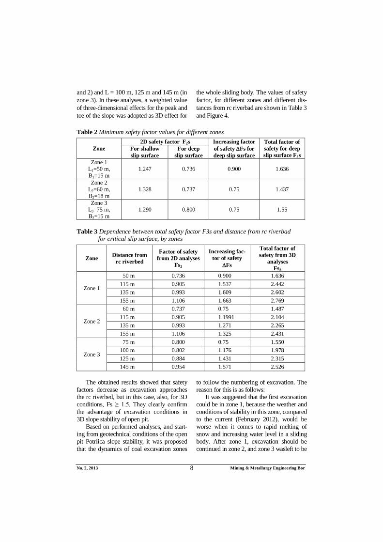
These analyses were performed with physical and mechanical parameters of soil and coal [13], which are determined based on the results of laboratory tests of soil and coal, [14] and are present in Table 1.
Table 1 Physical- mechanical parameters of soil and coal
Parameter of soil Waste Marlstone Clay Coal Unit weight ' (kN/m3) 19 20 21 13 Cohesion c/c’(kPa) 10 100 13 50 Angle of shear resistance ' (0) 15 30 15 20
Stability analyses were done for typical
geotechnical models of terrain and maxi-mum water levels [15], and for earthquake with seismic coefficient Ks = 0.04. All cal-culations were done for drained conditions in the field, i.e. with the effective shear strength parameters of soil and coal (c ', ')
Starting from the geotechnical conditions at the open pit, three-dimensional stability analyses were performed by analyzing sta-bility of one characteristic slice for each sliding surface, so obtained an increment of safety factor Fs is then attributed to all potential / actual sliding body. This presents, anyway, a simplified procedure for 3D ana-lysis, but bearing in mind the shape and size of t sliding bodies, given the level of explo-ration of open pit, which was performed for 2D analysis (depth and shape of sliding sur-face and sliding bodies), as well as given degree of reliability of shear strength para-meters, obtained by laboratory experiments, it is believed that this method is adequate.
In literature, 3D analyses were per-formed, as a rule, adopting lateral resistance of soil on both sides of the sliding body. However, due to gradual excavation of coal, for coal has to be excavated, the lateral re-sistance only on one side of the sliding body was taken into account, while in coal in the upper part of the slope, which remains unex-cavated, lateral resistance acting on both sides of sliding body. But for upper part of slope, due to coal excavation technology and the inability to previously excavated slices backfill by stone mound immediately after excavation, it was adopted the width of slice where 3D conditions are realized B' = 2B (B = width of lamella excavation).
Please note that it was assumed in the 3D stability analysis that the lateral sliding re-sistance occurs only in the coal layer. The reason for this is that thus obtained solution is independent of any changes in configura-tion of upper part of slope. At the same time, it is on the side of safety.

No. 2, 2013 Mining & Metallurgy Engineering Bor
6
4 ANALYSIS OF THE RESULTS OBTAINED BY CALCULATIONS THE OPEN PIT SLOPE STABILITY
Stability analyses were performed for shallower and deeper slip surfaces which were mostly along the clay layers - on its contact with marlstone or coal as well as in the basement under coal SEAM. The-se analyses involved two typical cases, i.e. when the sliding surface starting be
fore rc riverbed Čehotina and with its bed.
The results of calculation show that, due to geotechnical conditions in the ter-rain, and bearing in mind coal excavation technology, it was suitable to divide the surface excavation into three zones: 1, 2, and 3 (Figure 2).
Figure 2 Situation with defined zones of excavation
For all these zones, two-dimensional
analyses showed that critical slip surfaces were deep, and passed along the clay lay-ers in the basement of coal (Figure 3).
However, deep sliding bodies that pass through coal layer, if coal mining is done in
gradual linear lamellas excavation, are ex-posed to a lateral pressure of surrounding coal so they are in 3D stress-strain state. Therefore, stability analysis was carried out as follows:

No. 2, 2013 Mining & Metallurgy Engineering Bor
7
Figure 3 Results of 2D analysis stability for zone 3
- For shallow sliding surfaces, which are
in 2D stress-strain state, and which pass along contact of marlstone and clay, the distance L was determined between rc bed and toe of slope with condition that F ≥ 1.25.
- For such obtained distance L, the safety factors of 2D and 3D stability analysis were determined for deep sliding sur-face that runs along the clay underlain coal. The results showed that in this case for 3D conditions Fs ≥ 1.5. In ac-cordance with coal excavation tech-nology and required lateral resistance on side slopes, a width of lamella B = 15 m (for zones 1 and 3) and B = 18 m for zone 2 was adopted.
In such way, the distances L, between the upper part and toe of slopes, i.e. distan-
ces between rc bed and final excavation face, were determined. By these estimates, the minimum values of the safety factor Fs, shown in Table 2, were obtained.
In calculation process, significantly hig-her increases in safety factor values Fs than it could be found in literature, were obtained [16]. The reason for this lies in the fact that parameters of shearing resistance along la-teral sides of lamellas were much higher than shear resistance along the surface.
Within the stability analyses, the stabil-ity of slopes was checked during the slice excavation of coal. In performing that, the sliding surface was analyzed when the dis-tance L, from the edge of rc bed to the final coal excavation, has the following values: L = 115 m, 135 m and 155 m (for zones 1
No. 2, 2013 Mining & Metallurgy Engineering Bor
8
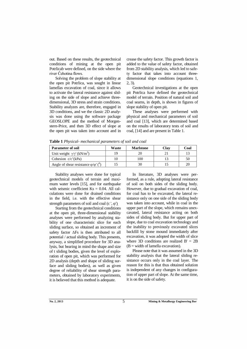
and 2) and L = 100 m, 125 m and 145 m (in zone 3). In these analyses, a weighted value of three-dimensional effects for the peak and toe of the slope was adopted as 3D effect for
the whole sliding body. The values of safety factor, for different zones and different dis-tances from rc riverbad are shown in Table 3 and Figure 4.
Table 2 Minimum safety factor values for different zones
Zone 2D safety factor F2s Increasing factor
of safety Fs for deep slip surface
Total factor of safety for deep slip surface F3s
For shallow slip surface
For deep slip surface
Zone 1 L1=50 m, B1=15 m
1.247 0.736 0.900 1.636
Zone 2 L2=60 m, B2=18 m
1.328 0.737 0.75 1.437
Zone 3 L3=75 m, B3=15 m
1.290 0.800 0.75 1.55
Table 3 Dependence between total safety factor F3s and distance from rc riverbad for critical slip surface, by zones
Zone Distance from rc riverbed
Factor of safety from 2D analyses
Fs2
Increasing fac-tor of safety
Fs
Total factor of safety from 3D
analyses Fs3
Zone 1
50 m 0.736 0.900 1.636 115 m 0.905 1.537 2.442 135 m 0.993 1.609 2.602 155 m 1.106 1.663 2.769
Zone 2
60 m 0.737 0.75 1.487 115 m 0.905 1.1991 2.104 135 m 0.993 1.271 2.265 155 m 1.106 1.325 2.431
Zone 3
75 m 0.800 0.75 1.550 100 m 0.802 1.176 1.978 125 m 0.884 1.431 2.315 145 m 0.954 1.571 2.526
The obtained results showed that safety
factors decrease as excavation approaches the rc riverbed, but in this case, also, for 3D conditions, Fs ≥ 1.5. They clearly confirm the advantage of excavation conditions in 3D slope stability of open pit.
Based on performed analyses, and start-ing from geotechnical conditions of the open pit Potrlica slope stability, it was proposed that the dynamics of coal excavation zones
to follow the numbering of excavation. The reason for this is as follows:
It was suggested that the first excavation could be in zone 1, because the weather and conditions of stability in this zone, compared to the current (February 2012), would be worse when it comes to rapid melting of snow and increasing water level in a sliding body. After zone 1, excavation should be continued in zone 2, and zone 3 wasleft to be

No. 2, 2013 Mining & Metallurgy Engineering Bor
9
the last because it was backfilled and had a role of buttresses, i.e. it contributed to the
increasing stability of entire slope next to the rc riverbed.
Figure 4 Distance from rc riverbed versus critical total factor of safety
In this way, for a period of four months
(February-June 2012) 60.000 tons of coal, i.e. coal from all three pre-defined zones, was excavated without any problems. After that, this part of open pit was closed. This fact confirms the validity of methodology which was applied in solving the problems of slope stability of open pit mine. Regard-ing to this, it should be noted that these anal-yses are beyond the standard procedures of slope stability analyses and involve complex engineering analysis and evaluation. At the same time, for the successful solving of this problem, the major importance was a good cooperation of mining engineers and ge-otechnical engineers.
5 CONCLUSION
Results of performed 3D analysis of slope stability at the open pit m have shown that it is possible, from the geotechnical as-pects, to make a rational coal exploitation, even after beginning the local instability on the slope of open pit. Due to 3D slope stabil-ity analyses, the following is proposed:
- Area of excavation should be divided into three zones, and coal excavation
carry out by linear lamellas of deter-mined width in each zone, and thus take into account the conditions of slope stability and open pit coal exca-vation technology.
- Width of linear lamellas excavation in each zone, which enables both activa-tion the required lateral resistance to sliding of slope and 3D conditions, could be realized as well as the smooth operation of machinery during coal ex-cavation.
- Minimum distance between the front part of slope and final slope excava-tion, i.e. length of safe excavation slope that provides the necessary safety slope of open pit.
The values of safety factors, obtained from comparative 2D and 3D stability anal-yses, clearly show that if during t excavation 3D conditions could be realized, greater quantity of coal could be excavated than when it would be done in 2D stability condi-tions.
In this way, the additional 60.000 tons of coal were excavated, i.e. coal from all three zones, and that part of open pit is closed. This fact confirms the validity of method-

No. 2, 2013 Mining & Metallurgy Engineering Bor
10
logy that was used in solving the problems of open pit slope stability.
Finally, it is specially emphasize that for successful solution of this and similar prob-lems, the most important is good coopera-tion of mining engineers and geotechnical engineers.
REFERENCES
[1] G. Gitirana Jr, M. A. Santos, M. Fred-lund: Three-dimensional Analysis of the Lodalen Landslide, GeoCongres, New Orleans, LA, USA, 2008.
[2] N. Albataineh: Slope Stability Analysis Using 2d and 3d Methods, 2006. Master of Science, University of Akron, Civil Engineering, 2006. 143p., www.etd.ohiolink.edu
[3] L. Lam and D. G. Fredlund,1993. A general limit-equilibrium model for three-dimensional slope stability analysis. Canadian Geotechnical Journal, 30, (1993), 905–919.
[4] S. Ćorić: Geostatic calculations (in Serbian), University in Belgrade, Faculty of Mining and Geology and Journal Construction, Belgrade, 2006, p.460.
[5] N. R. Morgenstern, V. E. Price: The analysis of the stability of general slip surfaces, Geotechnique, 1965., Vol. 15. No. 1.
[6] D. G., Fredlund, and J. Krahn, J.: Comparison of slope stability analysis. Canadian Geotechnical Journal, 14, (1977), 429–439.
[7] T. D. Stark & H. T. Eid: 1998. Perfor-mance of three-dimensional slope stability analysis method in practice. Journal of Geotechnical Engineering, ASCE, 124, (1998), 1049–1060.
[8] J. M. Duncan: State of the art: Limit equilibrium and finite element analysis of slopes. Journal of Geotechnical Engineering. ASCE, 122(7), (1996), 577–596.
[9] R. L. Michalowski, R. L. 1980. Three-dimensional analysis of locally loaded slopes. Géotechnique, 39, (1980), 27–38.
[10] D. Leshchinsky and R. Baker, R: Three dimensional analysis of slope stability. Soils and Foundations, 26(4), (1986), 98–110.
[11] S. Ćorić, L. Čaki, D. Rakić, S. Jotić, B. Ubiparip, M. Ljubojev: Three-dimen-sional aspects slope stability analyses, Journal: Mining Engineering, Publi-shed by Mining and metallurgy institute Bor, No 3/2011 (2011), Bor, str. 41-51, ISSN 1451-0162.
[12] M. Ljubojev, D. Ignjatović, V. Lju-bojev, L. Đurđevac Ignjatović, D. Ra-kić, “Deformation and bearing capacity of buried material near the shaft opening at the open pit mine “Zagradje” – open pit 2” Journal: Mining Engineering, Mining and Metallurgy Institute Bor, No. 2/2010, pp. 115-122, 2010, ISSN 1451-0162.
[13] D. Rakić, L. Čaki, S. Ćorić, M. Ljubo-jev: “Residual strength parameters of high plasticity clay and alevrites from open-pit mine “Tamnava - West field”, Journal: Mining Enginerering, Mining and Metallurgy Institute Bor, No. 1/2011, pp. 39-48, 2011, ISSN 1451-0162.
[14] Study of the stability analyzes and geotechnical conditions for excavation of coal for the open pit Potrlica - NW part Cementara - Zone Slapište, University in Belgrade, Faculty of Mining and Geology and Coal Mine Pljevlja (in Serbian), February 2012.
[15] G. Hadži - Niković: Constitutive rela-tionships of unsaturated soils in Belgrade area (in Serbian), PhD theses, University in Belgrade, Faculty of Mining and Geology, Belgrade, 2005, p. 297.
[16] J. M. Duncan, S. G.Wright: Soil Strength and Slope Stability, John Wiley & Sons Inc., 2005.

Broj 2, 2013. Mining & Metallurgy Engineering Bor
11
INSTITUT ZA RUDARSTVO I METALURGIJU BOR ISSN: 2334-8836 UDK: 622
UDK: 622.271/.33:681.325(045)=861 DOI:10.5937/MMEB1302001H
Gordana Hadži-Niković*, Slobodan Ćorić*, Jagoš Gomilanović**
PRIMENA 3D ANALIZE STABILNOSTI KOSINA PRI DEFINISANJU USLOVA ISKOPA UGLJA U
POVRŠINSKIM KOPOVIMA***
Izvod
Trodimenzionalna analiza stabilnosti kosina (3D) ima brojne prednosti nad dvodimenzionalnom (2D), pre svega zbog realnijeg prikaza geometrije kosine i klizne površine, ali i uvažavanja sila bočnog otpora na obodnim stranama kosine. Na osnovu brojnih 2D analiza metodom Morgenstern-Prajs određene su kritične klizne površine, a zatim su za njih određeni 3D faktori sigurnosti uvažavanjem bočnog otpora na stranama kosina iskopa. Na osnovu rezultata 3D analiza stabilnosti predloženo je izvođenje iskopa po zonama i za svaku zonu definisane su širine kampadnog iskopa i bezbedna rastojanja iskopa od čeonog dela kosine. Veličine faktora sigurnosti, dobijene iz uporednih 2D i 3D analiza stabilnosti, nedvosmisleno pokazuju da ukoliko se u toku iskopa ostvare 3D uslovi, što je slučaj kod kampadnog iskopa, onda se mogu da iskopaju daleko veće količine uglja nego kada se iskop vrši u 2D uslovima stabilnosti.
Ključne reči: 3D analize stabilnosti, površinski kop, kampadni iskop, bočni otpor, faktor sigurnosti
* Univerzitet u Beogradu, Rudarsko-geološki fakultet, Đušina 7, Beograd, [email protected] ** Rudnik uglja Pljevlja, Pljevlja, Republika Crna Gora ***Ovaj rad je realizovan u okviru projekta broj 36014 koji se finansira od strane Ministarstva prosvete,
nauke i tehnološkog razvoja Republike Srbije, za period 2011 – 2014.
1. UVOD
Potreba za primenom trodimenzionalne analize stabilnosti kosina počiva na činjenici da su klizanja u terenu, sama po sebi, trodimenzionalna. Klizno telo u prostoru ima i treću dimenziju. Dakle, svako pred-stavljanje trodimenzionalnog fenomena dvodimenzionalnom aproksimacijom, pred-stavlja, u suštini, značajno uprošćavanje realnih uslova u terenu. Uspešnost inženjera geotehnike u praksi se, između ostalog i vrednuje po tome koliko su uspešni u dvodimenzionalnom uprošćavanju trodime-nzionalne geometrije [1].
Dvodimenzionalni pristup u analizama stabilnosti kosina je opšte prihvaćen u praksi, a zahtevani faktori sigurnosti u geotehničkom projektovanju se kreću od 1.3
do 1.5. Analize dobro istraženih i instru-mentalizovanih klizanja kosina se sprovode primenom dvodimenzionalnih povratnih analiza, čak iako je do klizanja došlo u trodimenzionalnim uslovima.
Postoji fundamentalna razlika u rezulta-tima analiza stabilnosti kosina u zavisnosti od toga da li se sprovodi dvodimenzionalna ili trodimenzionalna analiza. Poznato je naime, da se za jedan isti geotehnički presek terena, primenom 2D i 3D analize stabilnosti ne dobija ista kritična klizna površina. Čak i za homogenu kosinu i istu kliznu površinu, faktori sigurnosti iz 2D i 3D analize se razlikuju [2].
Razlika među rezultatima dobijenim primenom 2D i 3D analize stabilnosti

Broj 2, 2013. Mining & Metallurgy Engineering Bor
12
zavisi od geometrije kosine, heterogenosti litološkog sastava terena i parametara tla. Razlika u veličinama faktora sigurnosti, prema podacima iz literature, kreće se od 15% do 50% [3].
Potencijalno značajne razlike u dobi-jenim rezultatima, primenom 2D i 3D analiza stabilnosti kosina, čine vrednim napor da se 3D analize više koriste u rutinskoj geotehničkoj praksi. Međutim, postoji nekoliko razloga zašto se 3D analize stabilnosti ne koriste više u praksi. Među njima su najznačajniji:
- Nedostatak razumevanja da razlike u dobijenim rezultatima mogu biti velike,
- Nedostatak, za rutinsku primenu, jednostavnog softverskog alata,
- Prihvatanje mišljenja da su 2D analize, za koje postoje brojni softverski alati, dovoljno tačne i da daju rezultate na strani sigurnosti, tj.konzervativna rešenja. Ovakvo mišljenje može dove-sti do neekonimičnog projektovanja kosina ili do primene 2D analize i tamo gde to ne odgovara stvarnim uslovima u terenu [4].
Zbog toga, primena 3D analize stabil-nosti omogućava racionalnije geotehničko projektovanje kosina nasipa, jalovišta, deponija, ali i iskopa kod površinskih kopova. Strmiji nagibi kosina iskopa omogućavaju eksploataciju veće količine rude, ali strmiji nagibi kosina mogu dovesti do kritičnih uslova i klizanja kosina iskopa. U tim slučajevima, 3D analiza predstavlja moćno oruđe da se pronađe optimalno rešenje između stabilnog nagiba kosine iskopa i količine rude koja se bezbedno može izvaditi iz iskopa.
U radu je prikazan primer uspešne primene 3D analize stabilnosti pri defini-sanju geotehničkih uslova dalje eksploatacije uglja, obustavljene usled nastalog klizanja kosine u zoni slapišta PK Potrlica u Pljevljima. U prvom koraku je urađena klasična 2D analiza [4], uz primenu programskog paketa GEOSLOPE, metodom
Morgenstern-Price-a [5], a zatim je, u drugom koraku uzet u obzir 3D efekat kosine površinskog kopa i dobijeno je povećanje faktora sigurnosti. Ovaj priraštaj faktora sigurnosti Fs je dodat veličini faktora sigurnosi iz 2D analize F2s i tako je dobijen faktor sigurnosti kosine koji uvažava trodimenzionalne uslove u kosini F3s, tj.
FssFsF 23 (1)
Uvažavanje bočnog otpora duž kampadnog iskopa omogućilo je određi-vanje dužine bezbednog iskopa, čime je omogućena dalja eksploatacija uglja.
Na kraju, odredili smo zavisnost uku-pnog kritičnog faktora sigurnosti od rasto-janja čeonog dela kosine – dužine kosine, za različite zone iskopa. Nastavljenim iskopom, po preporukama koje su definisane nakon izvršenih brojnih 3D analiza stabilnosti kosina kopa, iskopano je dodatnih 60 000 t uglja, čime je opravdanost primene postupka 3D analize stabilnosti kosine potvrđena u praksi.
2. 2D – 3D ANALIZE STABILNOSTI
Dvodimenzionalne metode granične ravnoteže stabilnosti kosina međusobno se razlikuju po pretpostavkama koje se odnose na položaj i pravac međulamelarnih sila, kao i na uslove ravnoteže kliznog tela [6], ali se sve ograničavaju na ravanski ili dvodi-menzionalni problem u kojem se pretpo-stavlja da je širina kliznog tela beskonačna u smeru upravnom na vertikalni presek kroz kosinu. To naravno ne odgovara uslovima u terenu.
Aproksimacijom ravnog stanja defor-macije, uticaj „krajeva“ kosine, tj. otpora koji postoji na bočnim stranama kosine, u 2D metodama granične ravnoteže, praktično se zanemaruje. Pretpostavkom o beskonačno širokoj kliznoj površini eliminišu se nor-malne i smičuće otporne sile na stranama (krajevima kliznog tela), što ima za posle-dicu manje faktore sigurnosti, tj. konzer-vativna rešenja koja su na strani sigurnosti.

Broj 2, 2013. Mining & Metallurgy Engineering Bor
13
Trodimenzionalne metode granične ravnoteže mnogo više uvažavaju realne uslove u terenu, pre svega 3D oblik klizne površine i sile otpora na bočnim stranama kosine. Trodimenzionalna analiza postaje važna u slučajevima:
- Složenosti geometrije kosine, kada je teško odabrati reprezentativan dvodi-menzionalni presek kosine za analizu;
- Značajne promenljivosti geometrije kosine i klizne površine u bočnom pravcu;
- Izrazite heterogenosti i anizotropije kliznog tela;
- Lokalno opterećene kosine spoljnim opterećenjem;
- Kada je na osnovu komplikovane kombinacije parametara čvrstoće smicanja, pornog pritiska i geometrije kosine potrebno odrediti kritičnu kliznu površinu;
- Kada treba odrediti čvrstoću smicanja iz povratne analize [7].
Mada su razvijene metode granične ravnoteže i za trodimenzionalne slučajeve klizanja, problem u opštem slučaju postaje dosta složen, a potrebne su brojne pret-postavke da bi se pretvorio u statički odre-đeni slučaj. Kao i kod 2D metoda, i ovde se zahteva uspostavljanje izvesnih pretpo-stavki da bi problem stabilnosti predstav-ljao statički određen sistem. Postoji neko-liko načina da se to uradi: smanjenjem broja nepoznatih veličina, povećavanjem broja jednačina ravnoteže ili kombinacijom jednog i drugog kako bi se dobio isti broj nepoznatih veličina i jednačina ravnoteže. Analizirajući trodi-menzionalne analize stabilnosti metodama granične ravnoteže, može se zaključiti [8]:
- U 3D analizama stabilnosti dobijaju se veći faktori sigurnosti nego u 2D analizama. To su istakli brojni autori naučnih radova, počev od Baligh & Azzouz (1975), Giger & Krizek (1976), Azzouz et al. (1977), preko
Denhardt & Forster (1985), Lesh-chinsky et al. (1985), Gens et al. (1988), Xing (1988) do Michalov-skog [9] i Leshchinsky & Huang [1991]. Postoje naučni radovi u kojima su prikazani suprotni zaključci: Hovland (1977), Chen & Chameau, (1983) i Seed i ostali (1990), ali oni uglavnom sadrže izvesne netačnosti;
- Hutchinson & Sarma (1985) i Lesh-chinsky & Baker [10] su istakli da 2D i 3D analize treba da daju isti faktor sigurnosti u slučaju homogene kosine izgrađene od nekoherentnog tla, jer je kritična klizna površina plitka i paralelna površini terena;
- Azzouz i ostali (1981) i Leshchinsky & Huang (1992) su istakli da se, zanemarivanjem 3D efekta, pri odre-đivanju čvrstoće smicanja povratnom 2D analizom dobijaju nerealno viso-ki parametri čvrstoće smicanja.
Do danas trodimenzionalne metode nisu široko prihvaćene u praksi, pogotovo što je greška zanemarivanja treće dime-nzije u praksi obično na strani sigurnosti. Međutim, to nije uvek slučaj i tada je vrlo bitno da se uticaj treće dimenzije uvede u analizu stabilnosti.
U ovom radu je prikazan aproksimativni postupak koji uvodi trodimenzionalni efekat u proračun stabilnosti kosina. U vezi sa tim naglašavamo da su trodimenzionalni uslovi u terenu, kod analize stabilnosti kosina površinskog kopa, obezbeđeni samo ukoliko postoji bočni otpor pomeranju kliznog tela. Ovo se može postići tako što će se iskop uglja vršiti u lamelama - kampadama (kampadni iskop) i to sukcesivnim pome-ranjem, polazeći od stabilnih delova površinskog kopa.
Određivanje priraštaja faktora sigurnosti Fs, kojim se u analizu stabilnosti uvodi uticaj bočnog otpora tla (Sl.1), prikazaćemo u nastavku teksta [11]. Polazeći od jednačine (1) dobija se:

Broj 2, 2013. Mining & Metallurgy Engineering Bor
14
sin
2
23
W
TBsFsF (2)
gde je: AT - bočna smičuća sila
τ – napon smicanja duž bočne strane je-
dinične lamele A - površina bočne strane jedinične la-
mele ( mHA 0.1 )
Sl. 1. Bočni otpor klizanju karakteristične lamele kosine
W - težina jedinične lamele po m’
( mHW 0.1 ) H - visina lamele B - širina kampadnog iskopa - nagib klizne površine U razvijenom obliku jednačina (2) može
da se prikaže na sledeći način:
sin212 0
23
B
tgHKcsFsF
gde je: - zapreminska težina tla c, - parametri otpornosti na smicanje Ko=1-sin, koeficijent pritiska tla u
stanju mirovanja.
3. GEOTEHNIČKI USLOVI EKSPLOATACIJE UGLJA NAKON KLIZANJA
Krajem 2011. godine, područja opštine Pljevlja pretrpelo je jak zemljotres. Kao posledica toga razdvojile su se spojnice armirano - betonskog (ab) korita reke Ćeho-tine i voda je kroz njih počela da prodire u površinski kop Potrlica. To je izazvalo pomeranje terena oko ab korita i pojavile su se pukotine u kopu i saobraćajnici u blizini mosta. Da bi se ovaj proces klizanja terena umirio, izvršeno je potkipavanje u kopu kod mosta i na taj način je zaustavljeno pome-ranje terena.
U vezi sa tim, postavilo se pitanje dalje eksploatacija uglja u površinskom kopu Potrlica na onoj strani gde protiče reka Ćehotina. Naime, ranije analize stabilnosti
Broj 2, 2013. Mining & Metallurgy Engineering Bor
15
pretpostavljale su da u kop ne procuruje voda iz ab korita i za takve uslove, a za kritične klizne površine, dobijaju se faktori sigurnosti Fs = 1,1-1,3. Medjutim, veliki priliv vode iz ab korita koji je početkom 2012. god. iznosio i do 115 l/min, značajno je smanjio stabilnost kosina kopa koje se nalaze duž ab korita [12]. Da bi se ovaj problem prevazišao tj. da bi se omogućio iskop uglja na kopu, izvršili smo brojne geostatičke analize. Na osnovu dobijenih rezultata, definisali smo geotehničke uslove dalje eksploatacije uglja u površinskom kopu Potrlica, na onoj strani gde protiče reka Čehotina.
Rešenje problema stabilnosti kosina površinskog kopa Potrlica, potražili smo u kampadnom iskopu uglja, jer on omogućava da se aktivira bočni otpor pomeranju kosine tj. da se pri klizanju ostvare trodimen-zionalni, 3D naponsko deformacijski uslovi. Analize stabilnosti smo, stoga, vršili za 3D
uslove i sproveli smo ih tako što smo, najpre uradili klasične 2D analize, uz primenu programskog paketa GEOSLOPE, metodom Morgenstern-Price-a, a zatim smo uzeli u obzir 3D efekat kosine površinskog kopa i dobili povećanje faktora sigurnosti. Ovaj priraštaj faktora sigurnosti je dodat veličini faktora sigurnosi iz 2D analize i tako je dobijen faktor sigurnosti kosine koji uvažava trodimenzionalne uslove u kosini (jednačine 1, 2, 3).
Geotehničkim istraživanjima, koja su vršena na području površinskog kopa Potrlica, definisan je geotehnički model terena. Položaj prirodnih sredina, po dubini, prikazan je na prilozima analize stabilnosti kosina površinskog kopa.
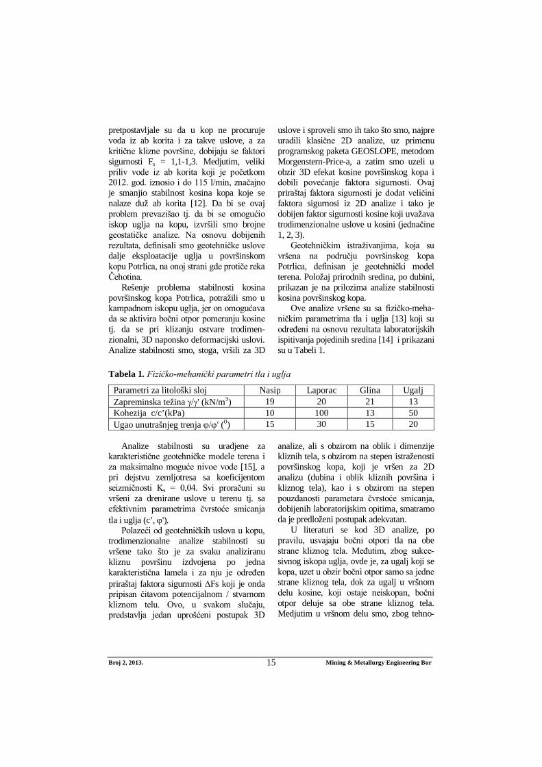
Ove analize vršene su sa fizičko-meha-ničkim parametrima tla i uglja [13] koji su određeni na osnovu rezultata laboratorijskih ispitivanja pojedinih sredina [14] i prikazani su u Tabeli 1.
Tabela 1. Fizičko-mehanički parametri tla i uglja
Parametri za litološki sloj Nasip Laporac Glina Ugalj Zapreminska težina ' (kN/m3) 19 20 21 13 Kohezija c/c’(kPa) 10 100 13 50 Ugao unutrašnjeg trenja ' (0) 15 30 15 20
Analize stabilnosti su uradjene za
karakteristične geotehničke modele terena i za maksimalno moguće nivoe vode [15], a pri dejstvu zemljotresa sa koeficijentom seizmičnosti Ks = 0,04. Svi proračuni su vršeni za drenirane uslove u terenu tj. sa efektivnim parametrima čvrstoće smicanja tla i uglja (c’, ').
Polazeći od geotehničkih uslova u kopu, trodimenzionalne analize stabilnosti su vršene tako što je za svaku analiziranu kliznu površinu izdvojena po jedna karakteristična lamela i za nju je određen priraštaj faktora sigurnosti Fs koji je onda pripisan čitavom potencijalnom / stvarnom kliznom telu. Ovo, u svakom slučaju, predstavlja jedan uprošćeni postupak 3D
analize, ali s obzirom na oblik i dimenzije kliznih tela, s obzirom na stepen istraženosti površinskog kopa, koji je vršen za 2D analizu (dubina i oblik kliznih površina i kliznog tela), kao i s obzirom na stepen pouzdanosti parametara čvrstoće smicanja, dobijenih laboratorijskim opitima, smatramo da je predloženi postupak adekvatan.
U literaturi se kod 3D analize, po pravilu, usvajaju bočni otpori tla na obe strane kliznog tela. Međutim, zbog sukce-sivnog iskopa uglja, ovde je, za ugalj koji se kopa, uzet u obzir bočni otpor samo sa jedne strane kliznog tela, dok za ugalj u vršnom delu kosine, koji ostaje neiskopan, bočni otpor deluje sa obe strane kliznog tela. Medjutim u vršnom delu smo, zbog tehno-

Broj 2, 2013. Mining & Metallurgy Engineering Bor
16
logije iskopa uglja i nemogućnosti da se prethodno iskopana lamela odmah po iskopu zapuni kamenim nabačajem, usvojili da širina na kojoj se realizuju 3D uslovi bude B’ = 2 B (B = širina kampadnog iskopa).
Napominjemo da smo u postupku 3D analize stabilnosti pretpostavili da se bočni otpor klizanju javlja samo u sloju uglja. Razlog za to je činjenica da ovako dobijeno rešenje ne zavisi od eventualnih promena konfiguracije vršnog dela kosine. U isto vreme, ono je i na strani sigurnosti.
4. ANALIZA REZULTATA DOBIJE-NIH PRORAČUNIMA STABILNOSTI KOSINA POVRŠINSKOG KOPA
Analize stabilnosti vršene su za pliće i dublje klizne površine koje najvećim delom prolaze duž slojeva gline – na njenom kontaktu sa laporcem ili ugljem kao i u podini ugljonosnog sloja. Ove analize obuhvatile su dva karakteristična slučaja tj. kada klizna površina počinje ispred ab korita reke Čehotine i kada obuhvata njeno korito.
Rezultati proračuna su pokazali da je, s obzirom na geotehničke uslove u terenu, kao i s obzirom na tehnologiju iskopa uglja, pogodno da se površina iskopa podeli u tri zone: 1. 2, 3 (Slika 2).
Sl. 2. Situacija sa izdvojenim zonama iskopa
Za sve ove zone, dvodimenzionalne
analize su pokazale da su kritične duboke klizne površine, koje prolaze duž slojeva gline, u podini uglja (Slika 3).
Međutim, duboka klizna tela koja prolaze kroz ugalj, ukoliko se iskop uglja
vrši sukcesivno u lamelama (kampadni iskop), izložena su bočnom pritisku okol-nog uglja tako da se nalaze u 3D naponsko-deformacijskom stanju. Stoga smo analize stabilnosti vršili na sledeći način:

Broj 2, 2013. Mining & Metallurgy Engineering Bor
17
Sl. 3. Rezultati 2D analize stabilnosti za zonu 3
- za plitke klizne površine, koje su u 2D
naponsko-deformacijskom stanju, i kod kojih klizna površina prolazi duž kontakta laporca i gline odredili smo rastojanje L izmedju ab korita i nožice kosine uz uslov da je Fs ≥ 1,25.
- za ovako određeno rastojanje L odredili smo faktore sigurnosti iz 2D i 3D analize stabilnosti za duboku kliznu površinu koja prolazi duž gline u podini uglja. Dobijeni rezul-tati su pokazali da je u ovom slučaju za 3D uslove Fs ≥ 1,5. Saglasno tehnologiji iskopa uglja i potrebnom bočnom otporu pomeranju kosine, usvojili smo širine lamela B = 15m (za zone 1 i 3) i B=18 m za zonu 2.
Na ovoj način su određena rastojanja L izmedju čeonog dela i nožice kosine tj. izmedju ab korita i završnog čela iskopa uglja. Ovim proračunima dobijene su mi-
nimalne vrednosti faktora sigurnosti Fs, prikazane u Tabeli 2.
U postupku proračuna su dobijena znatno veća povećanja faktora sigurnosti Fs nego što se to može naći u literaturi [16]. Razlog za to leži u činjenici da su parametri otpornosti smicanja duž bočnih strana znatno veći nego parametri otpor-nosti smicanja duž klizne površine.
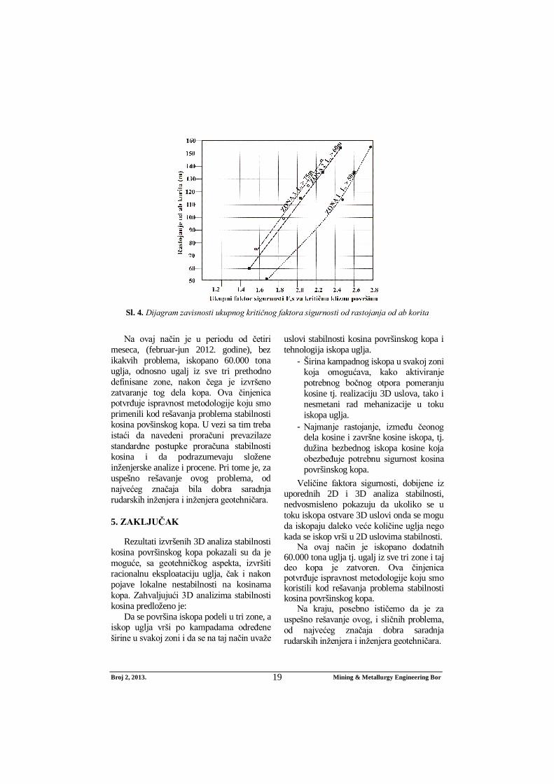
U okviru analiza stabilnosti proverili smo i stabilnost kosina u toku kampadnog iskopa uglja. Pri tome smo analizirali klizne površine kada rastojanje L, od ivice ab korita do iskopanog uglja, ima sledeće vrednosti: L = 115 m, 135 m i 155 m (za zone 1 i 2) i L = 100 m, 125 m i 145 m (za zonu 3). U ovim analizama smo kao 3D efekat, za čitavo klizno telo, usvojili ponderisanu vred-nost trodimenzionalnih efekata za vršni i no-žični deo kosine. Veličine faktora sigurnosti, za različite zone i različita rastojanja od ab korita, prikazane su u Tabeli 3 i na Slici 4.

Broj 2, 2013. Mining & Metallurgy Engineering Bor
18
Tabela 2. Minimalne vrednosti faktora sigurnosti za različite zone
Zona
Faktor sigurnosti iz 2D analize F2s
Priraštaji faktora sigurnosti Fs za
duboku kliznu površinu
Ukupni faktor sigurnosti za
duboku kliznu površinu F3s
Za plitku kliznu
površinu
Za duboku kliznu
površinu Zona 1
L1=50 m, B1=15 m
1.247 0.736 0.900 1.636
Zona 2 L2=60 m, B2=18 m
1.328 0.737 0.75 1.437
Zona 3 L3=75 m, B3=15 m
1.290 0.800 0.75 1.55
Tabela 3. Zavisnost ukupnog faktora sigurnosti F3s od rastojanja od ab korita za kritičnu kliznu površinu, po zonama
Zona Rastojanje od ab korita
Faktor sigurnosti dobijen iz 2D
analize Fs2
Priraštaj faktora sigurnosti
Fs
Ukupni faktor sigurnosti
dobijen iz 3D analize
Fs3
Zona 1
50 m 0.736 0.900 1.636 115 m 0.905 1.537 2.442 135 m 0.993 1.609 2.602 155 m 1.106 1.663 2.769
Zona 2
60 m 0.737 0.75 1.487 115 m 0.905 1.1991 2.104 135 m 0.993 1.271 2.265 155 m 1.106 1.325 2.431
Zona 3
75 m 0.800 0.75 1.550 100 m 0.802 1.176 1.978 125 m 0.884 1.431 2.315 145 m 0.954 1.571 2.526
Dobijeni rezultati su pokazali da se fak-
tori sigurnosti smanjuju kako se iskop uglja približava ab koritu, ali je i u ovom slučaju za 3D uslove, Fs ≥ 1,5. Oni nedvosmisleno potvrđuju prednost iskopa u 3D uslovima stabilnosti kosina površinskog kopa.
Na osnovu izvršenih analiza, a polazeći od geotehničkih uslova stabilnosti kosina površinskog kopa Potrlica, predložili smo da dinamika iskopa uglja prati numeraciju zona iskopa. Razlog za to je bio sledeći:
Predložili smo da se prvo vrši iskop u zoni 1, jer će se uslovi stabilnosti u ovoj zoni, u odnosu na trenutne (februar 2012. godine), pogoršati kada dodje do naglog topljenja snega i povećanja vode u kliznom telu. Posle zone 1, treba preći na zonu 2, a zonu 3 ostavili smo da bude poslednja zato što je ona potkipana i imala je ulogu kontra-fora tj. doprinosila je povećanju stabilnosti čitave kosine u području ab korita.
Broj 2, 2013. Mining & Metallurgy Engineering Bor
19
Sl. 4. Dijagram zavisnosti ukupnog kritičnog faktora sigurnosti od rastojanja od ab korita
Na ovaj način je u periodu od četiri
meseca, (februar-jun 2012. godine), bez ikakvih problema, iskopano 60.000 tona uglja, odnosno ugalj iz sve tri prethodno definisane zone, nakon čega je izvršeno zatvaranje tog dela kopa. Ova činjenica potvrđuje ispravnost metodologije koju smo primenili kod rešavanja problema stabilnosti kosina povšinskog kopa. U vezi sa tim treba istaći da navedeni proračuni prevazilaze standardne postupke proračuna stabilnosti kosina i da podrazumevaju složene inženjerske analize i procene. Pri tome je, za uspešno rešavanje ovog problema, od najvećeg značaja bila dobra saradnja rudarskih inženjera i inženjera geotehničara.
5. ZAKLJUČAK
Rezultati izvršenih 3D analiza stabilnosti kosina površinskog kopa pokazali su da je moguće, sa geotehničkog aspekta, izvršiti racionalnu eksploataciju uglja, čak i nakon pojave lokalne nestabilnosti na kosinama kopa. Zahvaljujući 3D analizima stabilnosti kosina predloženo je:
Da se površina iskopa podeli u tri zone, a iskop uglja vrši po kampadama određene širine u svakoj zoni i da se na taj način uvaže
uslovi stabilnosti kosina površinskog kopa i tehnologija iskopa uglja.
- Širina kampadnog iskopa u svakoj zoni koja omogućava, kako aktiviranje potrebnog bočnog otpora pomeranju kosine tj. realizaciju 3D uslova, tako i nesmetani rad mehanizacije u toku iskopa uglja.
- Najmanje rastojanje, između čeonog dela kosine i završne kosine iskopa, tj. dužina bezbednog iskopa kosine koja obezbeđuje potrebnu sigurnost kosina površinskog kopa.
Veličine faktora sigurnosti, dobijene iz uporednih 2D i 3D analiza stabilnosti, nedvosmisleno pokazuju da ukoliko se u toku iskopa ostvare 3D uslovi onda se mogu da iskopaju daleko veće količine uglja nego kada se iskop vrši u 2D uslovima stabilnosti.
Na ovaj način je iskopano dodatnih 60.000 tona uglja tj. ugalj iz sve tri zone i taj deo kopa je zatvoren. Ova činjenica potvrđuje ispravnost metodologije koju smo koristili kod rešavanja problema stabilnosti kosina površinskog kopa.
Na kraju, posebno ističemo da je za uspešno rešavanje ovog, i sličnih problema, od najvećeg značaja dobra saradnja rudarskih inženjera i inženjera geotehničara.

Broj 2, 2013. Mining & Metallurgy Engineering Bor
20
LITERATURA
[1] G. Gitirana Jr, M. A. Santos, M. Fredlund, Three-dimensional Analysis of the Lodalen Landslide, Geo-Con-gres, New Orleans, LA, USA, 2008.
[2] N. Albataineh, Slope Stability Analysis Using 2d and 3d Methods, 2006. Master of Science, University of Akron, Civil Engineering, 2006. 143 p., www.etd.ohiolink.edu
[3] L. Lam and D. G. Fredlund, 1993. A general limit-equilibrium model for three-dimensional slope stability analysis, Canadian Geotechnical Journal, 30 (1993), 905–919.
[4] S. Ćorić, Geostatički proračuni, Univerzitet u Beogradu, Rudarsko-geološki fakultet i Časopis Izgradnja, Beograd, 2006, str. 460.
[5] N. R. Morgenstern, V. E. Price, The analysis of the stability of general slip surfaces, Geotechnique, 1965., Vol.15. No.1.
[6] D. G., Fredlund, and J. Krahn, J., Comparison of slope stability analysis. Canadian Geotechnical Journal, 14, (1977), 429–439.
[7] T. D. Stark & H. T. Eid: 1998, Perfor-mance of three-dimensional slope stability analysis method in practice. Journal of Geotechnical Engineering, ASCE, 124, (1998), 1049–1060.
[8] J. M. Duncan: State of the art: Limit equilibrium and finite element analysis of slopes. Journal of Geotechnical Engineering. ASCE, 122(7), (1996), 577–596.
[9] R. L. Michalowski, R. L. 1980., Three-dimensional analysis of locally loaded slopes. Géotechnique, 39, (1980), 27–38.
[10] D. Leshchinsky and R. Baker, R,
Three dimensional analysis of slope stability. Soils and Foundations, 26(4), (1986), 98–110.
[11] S. Ćorić, L. Čaki, D. Rakić, S. Jotić, B. Ubiparip, M. Ljubojev: Trodimen-zionalni aspekti stabilnosti kosina, Rudarski radovi 3/2011(2011), Bor, str. 41-51.
[12] M. Ljubojev, D. Ignjatović, V. Ljubo-jev, L. Đurđevac Ignjatović, D. Rakić “Deformabilnost i nosivost nasutog materijala u neposrednoj blizini otvora okna na P.K. “Zagradje” Kop - 2”, Rudarski radovi 2/2010, str. 107-114, 2010, ISSN 1451-0162.
[13] D. Rakić, L. Čaki, S. Ćorić, M. Lju-bojev: “Rezidualni parametri čvrstoće smicanja visokoplastičnih glina i alevrita PK “Tamnava - Zapadno polje”, Rudarski radovi 1/2011, str. 29-38, 2011, ISSN 1451-0162.
[14] Studija o izvršenim analizama moguć-nosti iskopa uglja sa geotehničkog aspekta stabilnosti za PK Potrlica – SZ deo kopa Cementara - Zona Slapište, Univerzitet u Beogradu – Rudarsko-geološki fakultet i Rudnik uglja Pljevlja, februar 2012.
[15] G. Hadži-Niković: Konstitutivne zavis-nosti nezasićenih tla područja Beo-grada, doktorska disertacija, Univer-zitet u Beogradu, Rudarsko-geološki fakultet, Beograd, 2005, str. 297.
[16] J. M. Duncan, S. G. Wright: Soil Stre-ngth and Slope Stability, John Wiley & Sons Inc., 2005.