application notes for ascom dect handsets and … section describes the steps to configure the avaya...
TRANSCRIPT

QT; Reviewed:
SPOC 9/1/2011
Solution & Interoperability Test Lab Application Notes
©2011 Avaya Inc. All Rights Reserved.
1 of 36
AscomDectCS1K75
Avaya Solution & Interoperability Test Lab
Application Notes for Ascom DECT Handsets and Ascom
IP-DECT Base Station with Avaya Communication Server
1000 Release 7.5 – Issue 1.0
Abstract
These Application Notes describe a solution comprised of Avaya Communication Server 1000
SIP Line Release 7.5, Ascom DECT Handsets and Ascom IP-DECT Base Station. During the
compliance testing, the Ascom DECT Handsets and Ascom IP-DECT Base Station were able
to register as SIP client endpoints with Communication Server 1000 SIP Line gateway. The
Ascom DECT Handsets and Ascom IP-DECT Base Station were able to place and receive
calls from Communication Server 1000 Release 7.5 non-SIP and SIP Line telephones. The
compliance testing focused on basic telephone features.
Information in these Application Notes has been obtained through DevConnect compliance
testing and additional technical discussions. Testing was conducted via the DevConnect
Program at the Avaya Solution and Interoperability Test Lab.

QT; Reviewed:
SPOC 9/1/2011
Solution & Interoperability Test Lab Application Notes
©2011 Avaya Inc. All Rights Reserved.
2 of 36
AscomDectCS1K75
1. Introduction These application notes provide detail configurations of Avaya Communication Server 1000 SIP
Line Release 7.5 (hereafter referred to as CS 1000) and the Ascom DECT Handsets and Ascom
IP-DECT Base Station (hereafter referred to as Ascom DECT system) used during the
compliance testing. The Ascom DECT system was tested with non-SIP and SIP telephones using
CS1000 SIP line Release 7.5. All the applicable telephony feature test cases of Release 7.5 SIP
line were executed on the Ascom DECT system, where applicable, to ensure that the
interoperability with CS 1000.
2. General Test Approach and Test Results The general test approach was to have the Ascom DECT handset to register to the CS1000 SIP
line gateway. Calls were then placed from other CS1000 telephone clients/users to and from the
Ascom DECT handset. Other telephony features such as busy, hold, DTMF, MWI and codec
negotiation were also verified.
2.1. Interoperability Compliance Testing
Avaya’s formal testing and Declaration of Conformity is provided only on the headsets/handsets
that carry the Avaya brand or logo. Avaya may conduct testing of non-Avaya headset/handset to
determine interoperability with Avaya phones. However, Avaya does not conduct the testing of
non-Avaya headsets/handsets for: Acoustic Pressure, Safety, Hearing Aid Compliance, EMC
regulations, or any other tests to ensure conformity with safety, audio quality, long-term
reliability or any regulation requirements. As a result, Avaya makes no representations whether a
particular non-Avaya headset will work with Avaya’s telephones or with a different generation
of the same Avaya telephone.
Since there is no industry standard for handset interfaces, different manufacturers utilize
different handset/headset interfaces with their telephones. Therefore, any claim made by a
headset vendor that its product is compatible with Avaya telephones does not equate to a
guarantee that the headset will provide adequate safety protection or audio quality.
The focus of this testing was to verify that the Ascom DECT system was able to interoperate
with the CS 1000 SIP line system. The following areas were tested:
Registration of the Ascom DECT handset to the CS1000 SIP Line Gateway.
Call establishment of Ascom DECT handset with CS1000 SIP and non-SIP telephones.
Telephony features:
o Basic calls
o Conference (Avaya telephones host the conference).
o Blind and consultative transfer
o DTMF transmission
o Voicemail with Message Waiting Indication (MWI) notification
o Busy, hold, speed dial, call waiting, call park/pickup
o Call forward on Busy, No answer and All Calls

QT; Reviewed:
SPOC 9/1/2011
Solution & Interoperability Test Lab Application Notes
©2011 Avaya Inc. All Rights Reserved.
3 of 36
AscomDectCS1K75
PSTN calls over PRI trunk.
Codec negotiation
2.2. Test Results
The objectives outlined in Section 2.1 were verified. The following observations were made
during the compliance testing:
It is highly recommended to disable the media security on the Call Server to avoid some
unexpected behaviors such as one way audio from a call made from PSTN over a PRI
trunk.
MWI indicator being turned off by the NOTIFY message for the Do Not Disturb = no.
This issue is being addressed by Ascom with the RMS#18266. Avaya utilizes the SIP
NOTIFY message format of MWI (RFC 3842) for the Do Not Disturb message, which is
not covered in the mentioned RFC.
Local Call Waiting and Call Forward Busy are not support due to the CS1000 SIP line
gateway will always return 486 Busy Here.
2.3. Support
Technical support for the Ascom IP DECT product can be obtained through a local Ascom
supplier. Ascom global technical support:
Email: [email protected] or Help desk: +46 31 559450

QT; Reviewed:
SPOC 9/1/2011
Solution & Interoperability Test Lab Application Notes
©2011 Avaya Inc. All Rights Reserved.
4 of 36
AscomDectCS1K75
3. Reference Configuration Figure 1 illustrates the test configuration used during the compliance testing between the Avaya
CS1000 and the Ascom DECT system.
Figure 1: Network Configuration Diagram

QT; Reviewed:
SPOC 9/1/2011
Solution & Interoperability Test Lab Application Notes
©2011 Avaya Inc. All Rights Reserved.
5 of 36
AscomDectCS1K75
4. Equipment and Software Validated The following equipment and software was used during the lab testing:
Equipment Software Version Avaya CS1000E Call Server (CPPM): 7.50Q
Signaling Server (CPPM): 7.50.17
Avaya CallPilot™ Messaging System 5.0.1
Avaya IP Soft Phone 2050
Avaya IP Phone 1140
Avaya IP Phone 2004P2
Avaya IP Phone 2002P2
3.04.0003
0625C6O
0692D93
0604DC5
Avaya SIP 1140 02.02.21.00
Avaya Aura® Session Manager 6.1
Ascom Communication equipment DECT handsets firmware version:
- D41 : 3.0.6
- D62 : 3.0.9
- D81 : 3.0.16
IPBS Base Station (Access Point) Software
version 4.1.37 with boot code 4.1.24
5. Configure Avaya CS 1000 - SIP LINE This section describes the steps to configure the Avaya CS1000 SIP Line using CS 1000 Element
Manager. A command line interface (CLI) option is available to provision the SIP Line
application on the CS 1000 system. For detailed information on how to configure and administer
the CS 1000 SIP Line, please refer to Section 9 Reference [1].
The following is the summary of tasks needed to be done for configuring the CS 1000 SIP Line:
- Log in to Unified Communications Management (UCM) and Element Manager (EM).
- Enable SIP Line Service and Configure the Root Domain.
- Create SIP Line Telephony Node.
- Create D-Channel for SIP Line.
- Create an Application Module Link (AML).
- Create a Value Added Server (VAS).
- Create a Virtual Trunk Zone.
- Create a Route Data Block (RDB).
- Create SIP Line Virtual Trunks.
- Create SIP Line phones.

QT; Reviewed:
SPOC 9/1/2011
Solution & Interoperability Test Lab Application Notes
©2011 Avaya Inc. All Rights Reserved.
6 of 36
AscomDectCS1K75
5.1. Prerequisite
This document assumes that the CS1000 SIP Line server has been:
- Installed with CS 1000 Release 7.5 Linux Base.
- Joined CS 1000 Release 7.5 Security Domain.
- Deployed with SIP Line Application.
The following packages need to be enabled in the key code. If any of these features have not
been enabled, please contact your Avaya account team or Avaya technical support at
http://www.avaya.com.
Package Mnemonic Package # Descriptions Package Type Applicable market
SIP_LINES 417 SIP Line Service
package
New package Global
FFC 139 Flexible Feature
Codes
Existing package Global
SIPL_AVAYA 415 Avaya SIP Line
package
Existing package Global
SIPL_3RDPARTY 416 Third-Party SIP
Line Package
Existing package Global

QT; Reviewed:
SPOC 9/1/2011
Solution & Interoperability Test Lab Application Notes
©2011 Avaya Inc. All Rights Reserved.
7 of 36
AscomDectCS1K75
5.2. Log in to Unified Communications Management (UCM) and Element Manager (EM)
Use the Microsoft Internet Explorer browser to launch CS 1000 UCM web portal at http://<IP
Address or FQDN> where <IP address or FQDN> is the UCM Framework IP address or FQDN
for UCM server.
Log in with the username/password which was defined during the primary security server
configuration, the UCM home page appears as shown in the Figure 2 below.
Figure 2: The UCM Home Page of CS 1000 Release 7.5

QT; Reviewed:
SPOC 9/1/2011
Solution & Interoperability Test Lab Application Notes
©2011 Avaya Inc. All Rights Reserved.
8 of 36
AscomDectCS1K75
On the UCM home page, under the Element Name column, click on the EM name of CS 1000
system that needs to be configured, in this sample that is cpppm3. The CS 1000 Element
Manager page appears as shown in Figure 3 below.
Figure 3: CS 1000 Release 7.5 EM Home Page

QT; Reviewed:
SPOC 9/1/2011
Solution & Interoperability Test Lab Application Notes
©2011 Avaya Inc. All Rights Reserved.
9 of 36
AscomDectCS1K75
5.3. Enable SIP Line Service in the Customer Data Block
On the EM page, navigate to Customers on the left column menu; select the customer number to
be enabled with SIP Line Service (not shown).
- Enable SIP Line Service by clicking on the SIP Line Service check box.
- Enter the prefix number in the User agent DN prefix text box as shown in Figure 4.
Figure 4: SIP Line Service in Customers Data Block
QT; Reviewed:
SPOC 9/1/2011
Solution & Interoperability Test Lab Application Notes
©2011 Avaya Inc. All Rights Reserved.
10 of 36
AscomDectCS1K75
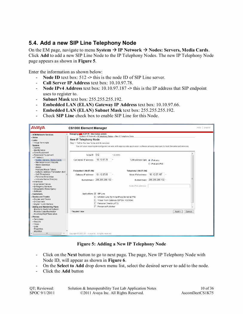
5.4. Add a new SIP Line Telephony Node
On the EM page, navigate to menu System IP Network Nodes: Servers, Media Cards.
Click Add to add a new SIP Line Node to the IP Telephony Nodes. The new IP Telephony Node
page appears as shown in Figure 5.
Enter the information as shown below:
- Node ID text box: 512 -> this is the node ID of SIP Line server.
- Call Server IP Address text box: 10.10.97.78.
- Node IPv4 Address text box: 10.10.97.187 -> this is the IP address that SIP endpoint
uses to register to.
- Subnet Mask text box: 255.255.255.192.
- Embedded LAN (ELAN) Gateway IP Address text box: 10.10.97.66.
- Embedded LAN (ELAN) Subnet Mask text box: 255.255.255.192.
- Check SIP Line check box to enable SIP Line for this Node.
Figure 5: Adding a New IP Telephony Node
- Click on the Next button to go to next page. The page, New IP Telephony Node with
Node ID, will appear as shown in Figure 6.
- On the Select to Add drop down menu list, select the desired server to add to the node.
- Click the Add button

QT; Reviewed:
SPOC 9/1/2011
Solution & Interoperability Test Lab Application Notes
©2011 Avaya Inc. All Rights Reserved.
11 of 36
AscomDectCS1K75
- Select the check box next to the newly added server, and click Make Leader (not
shown).
Figure 6: Adding a New IP Telephony Node (cont)
- Click on the Next button to go to next page. The SIP Line Configuration Detail page
appears as shown in Figure 7.
- Enter SIP Line domain name in SIP Domain name text box, for example sipl75.com.

QT; Reviewed:
SPOC 9/1/2011
Solution & Interoperability Test Lab Application Notes
©2011 Avaya Inc. All Rights Reserved.
12 of 36
AscomDectCS1K75
Figure 7: Adding a new IP Telephony Node (cont) - Under the SIP Line Gateway Service section, select MO from the SLG Role list.
- From the SLG Mode list, select S1/S2 (SIP Proxy Server 1 and Server 2), see Figure 8.
Figure 8: Adding a new IP Telephony Node (cont)
- Click Next. The Confirm new Node details page appears (not shown).

QT; Reviewed:
SPOC 9/1/2011
Solution & Interoperability Test Lab Application Notes
©2011 Avaya Inc. All Rights Reserved.
13 of 36
AscomDectCS1K75
- Click on the Transfer Now button and then The Synchronize Configuration Files
(Node ID 512) page appears.
- Click Finish and wait for the configuration to be saved. The Node Saved page appears,
see Figure 9.
Figure 9: Node Saved with Transfer Configuration
- Select the SIP Line server that associated with changes and then click on the Start Sync
button to transfer the configuration files to the selected servers, see Figure 10.
Figure 10: Synchronize Configuration Files
Note: The first time a new Telephony Node is added and transfered to the call server, the SIP
Line services need to be restarted. To restart the SIP Line services, log in as administrator to the
command line interface of the SIP Line server and issue command: appstart restart.

QT; Reviewed:
SPOC 9/1/2011
Solution & Interoperability Test Lab Application Notes
©2011 Avaya Inc. All Rights Reserved.
14 of 36
AscomDectCS1K75
5.5. Create a D-Channel for SIP Line
On the EM page, on the left column menu navigate to Routes and Trunks -> D-Channels.
Under the Configuration section as shown in Figure 11, enter a number in the Choose a D-
Channel Number field, and click on the to Add button.
Figure 11: D-Channels configuration page
- The D-Channels xx Property Configuration page appears as shown in Figure 12.
- From the Interface type for D-channel (IFC) list, select Meridian Meridian1 (SL1).
- Leave the other fields at default values.

QT; Reviewed:
SPOC 9/1/2011
Solution & Interoperability Test Lab Application Notes
©2011 Avaya Inc. All Rights Reserved.
15 of 36
AscomDectCS1K75
Figure 12: SIP Line D-Channel Property Configuration
- Click on the Basic options (BSCOPT) link. The Basic options (BSCOPT) list expands
(not shown).
- Click on Edit to configure Remote Capabilities (RCAP) (not shown). The Remote
Capabilities Configuration detail page will appear as shown in Figure 13.
- Select the Message waiting interworking with DMS-100 (MWI) check box.
- Select the Network name display method 2 (ND2) check box.
- At the bottom of the Remote Capabilities Configuration page, click Return - Remote
Capabilities to return the D-Channel xx Property Configuration page.

QT; Reviewed:
SPOC 9/1/2011
Solution & Interoperability Test Lab Application Notes
©2011 Avaya Inc. All Rights Reserved.
16 of 36
AscomDectCS1K75
Figure 13: SIP Line D-Channel RCAP Configuration Details
- Message Waiting Interworking with DMS-100 (MWI) must be enabled to support
voice mail notification on SIP Line endpoints.
- Network Name Display Method 2 (ND2) must be enabled to support name display
between SIP Line endpoints.
- Other check boxes are left unchecked.
Click on the Submit button of the D-Channel Property Configuration page to save changes.

QT; Reviewed:
SPOC 9/1/2011
Solution & Interoperability Test Lab Application Notes
©2011 Avaya Inc. All Rights Reserved.
17 of 36
AscomDectCS1K75
5.6. Create an Application Module Link (AML)
On the EM page, navigate to System -> Interfaces -> Application Module Link, click on the
Add button to add a new Application Module Link (not shown). The New Application Module
Link page appears as shown in Figure 14.
Enter an AML port number in the Port number text box. The AML of SIP Line Service can use
a port from 32 to 127. In this case, SIP Line Service is configured to use port 33.
Click on the Save button to complete addition of the AML link and to save the configuration.
Figure 14: Adding a new AML

QT; Reviewed:
SPOC 9/1/2011
Solution & Interoperability Test Lab Application Notes
©2011 Avaya Inc. All Rights Reserved.
18 of 36
AscomDectCS1K75
5.7. Create a Value Added Server (VAS)
On the EM page, navigate to System -> Interfaces -> Value Added Server and click on the
Add button to add a new VAS.
The Value Added Server page appears (not shown), in this page, select the Ethernet Link link
and the Ethernet Link page appears as shown in Figure 15.
Enter a number in the Value added server ID field, in this example 33 was used. In the
Ethernet LAN Link drop down list, select the AML number of ELAN that was created in the
Section 5.6.
Leave other fields as default values and click on the Save button to complete adding the VAS
and save the configuration.
Figure 15: Adding a new Value Added Service for the AML

QT; Reviewed:
SPOC 9/1/2011
Solution & Interoperability Test Lab Application Notes
©2011 Avaya Inc. All Rights Reserved.
19 of 36
AscomDectCS1K75
5.8. Create a Virtual Trunk Zone
On the EM page, navigate to menu System -> IP Network -> Zones. The Zones page appears
on the right, in this page select Bandwidth Zones link (not shown).
On the Bandwidth Zones page, click on the Add button (not shown), the Zone Basic Property
and Bandwidth Management page appears as shown in Figure 16.
Enter a zone number in the Zone Number (ZONE) field and in the Zone Intent (ZBRN) drop
down menu select VTRK (VTRK).
Leave other fields as default values and click on the Save button to complete adding the Zone.
Note: Repeat the step above to create another zone for the SIP Line phone; however remember to
select MO, instead of VTRK in the field Zone Intent.
Figure 16: Adding a new Zone for Virtual Trunk

QT; Reviewed:
SPOC 9/1/2011
Solution & Interoperability Test Lab Application Notes
©2011 Avaya Inc. All Rights Reserved.
20 of 36
AscomDectCS1K75
5.9. Create a SIP Line Route Data Block (RDB)
On the EM page, navigate to the menu Routes and Trunks -> Routes and Trunks; the Routes
and Trunks page appears (not shown). In this page, click on the Add route button next to the
customer number that the route will belong to.
The Customer ID, New Route Configuration page appears, expand the Basic Configuration
tab, and enter values below and as shown in Figure 17 and 18.
- Route Number (ROUT): 3
- Trunk type(TKTP): TIE
- Incoming and Outgoing trunk (ICOG): IAO
- Access Code for Trunk group (ACOD): enter a number for ACOD, for example 7575.
- The route is for a virtual trunk route (VTRK): Checked.
- Zone for codec selection and bandwidth management (ZONE): 4, this is the Virtual
trunk zone number that created in the Section 5.8.
- Node ID of signaling server of this route (NODE): 512, this is the node ID of the SIP
Line.
- Protocol ID for the route (PCID): SIP Line (SIPL).
- Integrated services digital network option (ISDN): checked.
- Mode of operation (MODE): Route uses ISDN Signaling Link (ISLD).
- D channel number (DCH): 4, the D-channel number that was created in the Section 5.5.
- Interface type for route (IFC): Meridian M1 (SL1).
- Network calling name allowed (NCNA): checked.
- Channel type (CHTP): B-channel (BCH).
- Call type for outgoing direct dialed TIE route (CTYP): CDP.
- Calling Number dialing plan (CNDP): CDP.
Leave default values for The Basic Route Options, Network Options, General Options, and
Advanced Configurations sections.
Click the Submit button to complete adding the route and save configuration.

QT; Reviewed:
SPOC 9/1/2011
Solution & Interoperability Test Lab Application Notes
©2011 Avaya Inc. All Rights Reserved.
21 of 36
AscomDectCS1K75
Figure 17: SIP Line Route Configuration
Figure 18: SIP Line Route Configuration (cont)

QT; Reviewed:
SPOC 9/1/2011
Solution & Interoperability Test Lab Application Notes
©2011 Avaya Inc. All Rights Reserved.
22 of 36
AscomDectCS1K75
5.10. Create SIP Line Virtual Trunks
On the EM page, navigate to Routes and Trunks -> Routes and Trunks and select the Add
route button beside the route that was created in the Section 5.9 above to create new trunks.
The Customer ID, Route ID, and Trunk type TIE trunk data block page appears as shown in
Figure 19, enter values for fields as shown below:
- Multiple trunk input number (MTINPUT): 32 -> create 32 trunks.
- Auto increment member number: checked.
- Trunk data block (TYPE): IP Trunk (IPTI).
- Terminal Number (TN): 100 0 2 0 -> enter the first TN of a range TN.
- Member number: 33, this is ID of trunk, just enter the first ID for first trunk, next ID
will be automatically created and incremented.
- Start arrangement Incoming: Immediate (IMM).
- Start arrangement Outgoing: Immediate (IMM).
- Trunk Group Access Restriction (TGAR): 1.
- Channel ID for this trunk: 33, this ID should be the same with the ID of Member
Number.
Click on the Class of Service button and assign following class of services (not shown):
- Media security: Media Security Never (MSNV).
- Restriction level: Unrestricted.
Leave other fields at default values and click on the Return Class of Service button to return to
the Trunk type TIE trunk data block page.
Click on the Save button to complete adding virtual trunks for SIP Line.

QT; Reviewed:
SPOC 9/1/2011
Solution & Interoperability Test Lab Application Notes
©2011 Avaya Inc. All Rights Reserved.
23 of 36
AscomDectCS1K75
Figure 19: Adding virtual trunks for SIP Line Trunk
5.11. Create a SIP Line Phone
To create a SIP Line phone on the Call Server, log in as administrator using the command line
interface (CLI) and issue the overlay (LD) 11/20 as shown below.
The bold fields must be properly inputted as they are configured on the Call server, for other
fields hit enter to leave it at default values.

QT; Reviewed:
SPOC 9/1/2011
Solution & Interoperability Test Lab Application Notes
©2011 Avaya Inc. All Rights Reserved.
24 of 36
AscomDectCS1K75

QT; Reviewed:
SPOC 9/1/2011
Solution & Interoperability Test Lab Application Notes
©2011 Avaya Inc. All Rights Reserved.
25 of 36
AscomDectCS1K75
6. Configure Ascom DECT System
6.1. Configuration of the IP-DECT Base Station (IPBS)
This section describes how to access and configure the Ascom DECT system, namely IP-DECT
Base Station. Enter the URL (http://<IP Address>) of the Base station into a web browser and
select the “System administration” control as shown in Figure 20.
Figure 20: Ascom Webpage Administration
Log in with admin user and provided password (not shown). User will be directed to the IP-
DECT Base Station General Info page as shown in Figure 21.
Figure 21: Ascom IP-DECT Base Station Page

QT; Reviewed:
SPOC 9/1/2011
Solution & Interoperability Test Lab Application Notes
©2011 Avaya Inc. All Rights Reserved.
26 of 36
AscomDectCS1K75
Select the LAN -> IP tab. Verify that the IP parameters assigned to the base station correspond
to those which are configured in the DHCP reservation as shown in Figure 22.
Figure 22: Base Station LAN-IP page
Select the DECT System tab. Enter the parameters shown in red box and click “OK” as shown in
Figure 23.
Figure 23: Base Station DECT -> System Page

QT; Reviewed:
SPOC 9/1/2011
Solution & Interoperability Test Lab Application Notes
©2011 Avaya Inc. All Rights Reserved.
27 of 36
AscomDectCS1K75
Select the DECT Suppl. Serv. tab. Enter the parameters shown in red box and click “OK” as
shown in Figure 24.
Figure 24: Base Station DECT -> Suppl. Serv. Page

QT; Reviewed:
SPOC 9/1/2011
Solution & Interoperability Test Lab Application Notes
©2011 Avaya Inc. All Rights Reserved.
28 of 36
AscomDectCS1K75
Select the DECT -> Master tab. Enter the parameters shown in red box and click “OK” as shown in
Figure 25.
Figure 25: Base Station DECT -> Master Page
Select the DECT Radio tab. Enter the parameters shown in red box and click “OK”. If the Radio
configuration is correct then Status will be as shown in Figure 26.
Figure 26: Base Station DECT -> Radio Page

QT; Reviewed:
SPOC 9/1/2011
Solution & Interoperability Test Lab Application Notes
©2011 Avaya Inc. All Rights Reserved.
29 of 36
AscomDectCS1K75
Select the DECT SARI tab. Enter the parameters shown in red box and click “OK” as shown in
Figure 27. Note that SARI is provided by Ascom.
Figure 27: Base Station DECT -> SARI
Select the DECT Air Sync tab. Enter the parameters shown in red box and click “OK” as shown
in Figure 28.
Figure 28: Base Station DECT -> Air Sync

QT; Reviewed:
SPOC 9/1/2011
Solution & Interoperability Test Lab Application Notes
©2011 Avaya Inc. All Rights Reserved.
30 of 36
AscomDectCS1K75
Under the Administration left menu column, at the bottom, select Reset -> Reset then click
“OK” (not shown) for all the changes to take effect.
When the IPBS boots up and completed the reset process, under the Administration, select
Device Overview, user should see if the device and its radio are in sync as shown in Figure 29.
Figure 29: Base Station Device Overview Page
6.2. Configure Ascom IP-DECT Handsets
This section describes how to configure the IP-DECT handsets to subscribe to the IPBS access
point. And that will then register the set to the CS1000 SIP Line system by executing a provided
command via the handset.
On the IPBS administration webpage, select Users -> Users tab and click new to add a new user
as shown in Figure 30.
Figure 30: Base Station Users -> Users Page

QT; Reviewed:
SPOC 9/1/2011
Solution & Interoperability Test Lab Application Notes
©2011 Avaya Inc. All Rights Reserved.
31 of 36
AscomDectCS1K75
A new user dialog box will pop up. Enter the parameters shown in red box and click “OK” as
shown in Figure 31. Note the following:
Name Enter the name to be used for SIP communications.
Number Enter the extension to be assigned to the handset.
Auth. Name Enter the extension to be assigned to the handset.
Password Enter the password to be used to register the handset. This must match the valued
configured in Section 5.11 (SCPW = 1234 in this example).
Figure 31: New User Add Template
Select Users -> Users tab and click on show. The newly added user is appearing on the list as
shown in Figure 32.
Figure 32: Base Station Users -> Users -> show

QT; Reviewed:
SPOC 9/1/2011
Solution & Interoperability Test Lab Application Notes
©2011 Avaya Inc. All Rights Reserved.
32 of 36
AscomDectCS1K75
To subscribe the hand set to the IPBS, go to one of the handset d41/d62/d81. Select Menu ->
Connections -> System -> Subscribe -> Next (now shown). In the System name text box,
enter the system name as configured in Figure 26.
Select Next and enter the Park number and AC (not shown), which are the SARI and
PASSWORD should be SARI and SYSTEM AC, respectively as configured in Figure 27.
At the Protection on? (It can be ON or OFF) option, select No (OFF for this testing) then select
OK (not show) to start the subscription process from the handset to the IPBS access point.
Within 30 second or so, the message shows on the handset Subscription Successfully.
Now user can call *< Master ID>*<extension># and wait for “EXECUTED” before hanging
up (not shown).
On the IPBS Administration webpage, select Users -> Users tab and click show. The new
added user now subscribes to the IPBS and registers to the CS1000 SIP Line system as shown in
Figure 33.
Figure 33: Base Station with New User Subscribe and Register

QT; Reviewed:
SPOC 9/1/2011
Solution & Interoperability Test Lab Application Notes
©2011 Avaya Inc. All Rights Reserved.
33 of 36
AscomDectCS1K75
7. Verification Steps This section includes some steps that can be followed to verify the configuration.
Verify that the Ascom IP-DECT base station register successfully with the CS 1000 SIP
Line Gateway server and Call Server by using the CS 1000 Linux command line and CS
1000 Call Server overlay LD 32.
- Log in to the SIP Line server as an administrator by using Avaya account.
- Issue command “slgSetShowByUID [userID]” where userID is SIP Line user’s ID
being checked. [admin@sipl ~]$ slgSetShowByUID 54008
=== VTRK ===
UserID AuthId TN Clients Calls
SetHandle Pos ID SIPL Type
--------------- ---------- --------------- ------- ----- ---
------ ------- ---------
54008 54008 104-00-00-01 1 0
0x8fc4cf8 SIP Lines
StatusFlags = Registered Controlled KeyMapDwld SSD
FeatureMask =
CallProcStatus = 0
Current Client = 0, Total Clients = 1
== Client 0 ==
IPv4:Port:Trans = 10.10.98.76:5060:udp
Type = SIP3
UserAgent = (Ascom ID-DECT Base
Station/[4.1.37/4.1.24/IPBS1-A3/4F])
x-nt-guid = 267d228547c1562399f1f743a2971fb5
RegDescrip =
RegStatus = 1
PbxReason = OK
SipCode = 200
hTransc = (nil)
Expire = 3600
Nonce = f56a9946ba497bde7eb445efb518f4f1
NonceCount = 2
hTimer = 0x8f64e60
TimeRemain = 1338
Stale = 0
Outbound = 0
ClientGUID = 0
MSec CLS = MSNV (MSEC-Never)
Contact = sip:[email protected]:5060
KeyNum = 255
AutoAnswer = NO
Key Func Lamp Label
0 3 0 54008
1 126 0 2654008
2 9 0

QT; Reviewed:
SPOC 9/1/2011
Solution & Interoperability Test Lab Application Notes
©2011 Avaya Inc. All Rights Reserved.
34 of 36
AscomDectCS1K75
3 29 0
4 22 0
5 2 0 54334
17 16 0
18 18 0
19 27 0
20 19 0
21 52 0
22 25 0
24 11 0
25 30 0
26 31 0
== Subscription Info ==
Subscription Event = None
Subscription Handle = (nil)
SubscribeFlag = 0
- Log in to the call server using the admin account.
- Load overlay 32 and then issue command “stat [TN]” where TN is the SIP Line
user’s TN being checked
>ld 32
NPR000
.stat 104 0 0 1
IDLE REGISTERED 00
Place a call from and to Ascom DECT handset and verify that the call is established with
2-way speech path.
During the call, use a pcap tool (ethereal/wireshark) at the SIP Line Gateway and clients
to make sure that all SIP request/response messages are correct.
8. Conclusion All of the executed test cases have passed and met the objectives outlined in the Section 2.1,
with some exceptions outlined in Section 2.2. The Ascom DECT system is considered to be in
compliance with Avaya CS 1000 SIP Line System Release 7.5.

QT; Reviewed:
SPOC 9/1/2011
Solution & Interoperability Test Lab Application Notes
©2011 Avaya Inc. All Rights Reserved.
35 of 36
AscomDectCS1K75
9. Additional References [1] Product documentation for the Avaya CS 1000 products may be found at:
https://support.avaya.com/css/Products/
Avaya Communication Server 1000E Installation and Commissioning
Avaya Communication Server 1000 SIP Line Fundamental, Release 7.5
Avaya Communication Server 1000 Element Manager System Reference – Administration
Avaya Communication Sever 1000 Co-resident Call Server and Signaling Server
Fundamentals
Avaya Communication Server 1000 Unified Communications Management Common Services
Fundamentals.
Avaya Communication Server 1000 ISDN Primary Rate Interface Installation and
Commissioning
[2] Product documentation for the Ascom DECT products:
Installation and Operation Manual IP-DECT Base Station and IP-DECT Gateway (software
version 4.1.x) (TD 92579EN)
System Description Ascom IP-DECT System (TD 92375EN)
System Planning Ascom IP-DECT System (TD 92422GB)

QT; Reviewed:
SPOC 9/1/2011
Solution & Interoperability Test Lab Application Notes
©2011 Avaya Inc. All Rights Reserved.
36 of 36
AscomDectCS1K75
©2011 Avaya Inc. All Rights Reserved.
Avaya and the Avaya Logo are trademarks of Avaya Inc. All trademarks identified by ® and
™ are registered trademarks or trademarks, respectively, of Avaya Inc. All other trademarks
are the property of their respective owners. The information provided in these Application
Notes is subject to change without notice. The configurations, technical data, and
recommendations provided in these Application Notes are believed to be accurate and
dependable, but are presented without express or implied warranty. Users are responsible for
their application of any products specified in these Application Notes.
Please e-mail any questions or comments pertaining to these Application Notes along with the
full title name and filename, located in the lower right corner, directly to the Avaya
DevConnect Program at [email protected].