application manual - fronius tps 4000/5000 irc5...
TRANSCRIPT

ABB Robotics
Application manualFronius TPS 4000/5000 IRC5 Interface

© C
opyr
ight
200
6-20
13 A
BB
. All
rig
hts
rese
rved
.
Application manualFronius TPS 4000/5000
IRC5M2004
3HEA802920-001Revision B

© C
opyr
ight
200
6-20
07 A
BB
. All
rig
hts
rese
rved
.
The information in this manual is subject to change without notice and should not be construed as a commitment by ABB. ABB assumes no re-sponsibility for any errors that may appear in this manual.
Except as may be expressly stated anywhere in this manual, nothing herein shall be construed as any kind of guarantee or warranty by ABB for losses, damages to persons or property, fitness for a specific pur-pose or the like.
In no event shall ABB be liable for incidental or consequential damages arising from use of this manual and products described herein.
This manual and parts thereof must not be reproduced or copied without ABB's written permission, and contents thereof must not be imparted to a third party nor be used for any unauthorized purpose. Contravention will be prosecuted.
Additional copies of this manual may be obtained from ABB at its then current charge.
©Copyright 2006-2013 ABB All rights reserved.
ABB ABRobotics Products
SE-721 68 VästeråsSweden

Table of Contents
©Cop
yrig
ht 2
006-
2013
AB
B. A
ll r
ight
s re
serv
ed.
1 Introduction.......................................................................................................5
1.1 About Fronius TPS 4000/5000 IRC5 interface..........................................5
2 Installation and setup.......................................................................................7
2.1 Hardware . . . . . . . . . . . . . . . . . . . . . . . . . . . . . . . . . . . . . . . . . . . . . . . . . 7
2.1.1 DeviceNet setup. . . . . . . . . . . . . . . . . . . . . . . . . . . . . . . . . . . . . . . . 7
2.1.2 EtherNet/IP setup. . . . . . . . . . . . . . . . . . . . . . . . . . . . . . . . . . . . . . . 9
2.1.3 Fronius welding equipment description . . . . . . . . . . . . . . . . . . . . 14
2.2 Software ...................................................................................................15
2.2.1 Software requirements. . . . . . . . . . . . . . . . . . . . . . . . . . . . . . . . . . 15
3 Process settings .............................................................................................17
3.1 DeviceNet.................................................................................................17
3.1.1 Fronius Equipment Properties . . . . . . . . . . . . . . . . . . . . . . . . . . . . 18
3.1.2 Arc Equipment Standard IO . . . . . . . . . . . . . . . . . . . . . . . . . . . . . 20
3.1.3 Fronius Equipment IO . . . . . . . . . . . . . . . . . . . . . . . . . . . . . . . . . . 21
3.1.4 Fronius Weld Schedules . . . . . . . . . . . . . . . . . . . . . . . . . . . . . . . . 24
3.1.5 EtherNet/IP . . . . . . . . . . . . . . . . . . . . . . . . . . . . . . . . . . . . . . . . . . 25
4 Fronius interface modes ................................................................................31
4.1 Overview..................................................................................................31
4.1.1 General. . . . . . . . . . . . . . . . . . . . . . . . . . . . . . . . . . . . . . . . . . . . . . 31
4.2 Set interface mode....................................................................................32
4.3 JobMode...................................................................................................34
4.3.1 Weld Data Parameters . . . . . . . . . . . . . . . . . . . . . . . . . . . . . . . . . . 34
4.4 JobMode with Correction.........................................................................35
4.4.1 Weld Data Parameters . . . . . . . . . . . . . . . . . . . . . . . . . . . . . . . . . . 35
4.4.2 Changing the wirefeed Correction Settings. . . . . . . . . . . . . . . . . . 37
3HEA802920-001 Revision B 3

Table of contents
© C
opyr
ight
200
6-20
13 A
BB
. All
rig
hts
rese
rved
.
4.4.3 Changing the wirefeed speed units . . . . . . . . . . . . . . . . . . . . . . . . 38
4.5 ProgramMode...........................................................................................39
4.5.1 Weld Data Parameters . . . . . . . . . . . . . . . . . . . . . . . . . . . . . . . . . . 39
5 Fronius Error codes........................................................................................41
5.1 Error codes ...............................................................................................41
5.1.1 Fronius Error reporting . . . . . . . . . . . . . . . . . . . . . . . . . . . . . . . . . 41
5.1.2 Fronius Error Code List . . . . . . . . . . . . . . . . . . . . . . . . . . . . . . . . . 42
4 3HEA802920-001 Revision B

Introduction©
Cop
yrig
ht 2
006-
2013
AB
B. A
ll r
ight
s re
serv
ed.
1 Introduction
1.1 About Fronius TPS 4000/5000 IRC5 interface
IntroductionThis guide describes the ABB Robotics IRC5 interface for:
• Fronius TS/TPS 4000/5000 Power Source models with DeviceNet interface. The func-tionality described in this interface is part of the 650-9 sub-option to RobotWare Arc.
• Fronius Power Sources with EtherNet/IP interface. The power source has to meet the following requirements:• EtherNet/IP communication interface with software version 1.07.25 or later• PowerMAG OS version 4.30.18 or later
3HEA802920-001 Revision B 5

About Fronius TPS 4000/5000 IRC5 interface
© C
opyr
ight
200
6-20
13 A
BB
. All
rig
hts
rese
rved
.
6 3HEA802920-001 Revision B
Installation and setup©
Cop
yrig
ht 2
006-
2013
AB
B. A
ll r
ight
s re
serv
ed.
2 Installation and setup
2.1 Hardware
2.1.1 DeviceNet setup
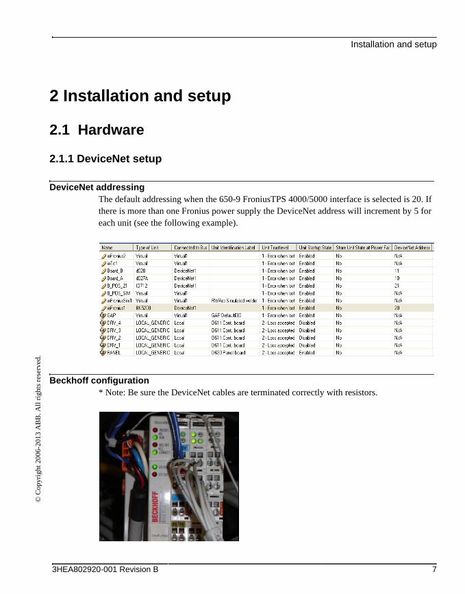
DeviceNet addressingThe default addressing when the 650-9 FroniusTPS 4000/5000 interface is selected is 20. If there is more than one Fronius power supply the DeviceNet address will increment by 5 for each unit (see the following example).
Beckhoff configuration* Note: Be sure the DeviceNet cables are terminated correctly with resistors.
3HEA802920-001 Revision B 7

DeviceNet setup
© C
opyr
ight
200
6-20
13 A
BB
. All
rig
hts
rese
rved
.
Set the Baud Rate to 500 kbps.
Wago Connector description from left to right.
Pin 1. 24 Volts
Pin 2. Can High
Pin 3. Ground Shield
Pin 4. Can Low
Pin 5. O Volts
8 3HEA802920-001 Revision B

EtherNet/IP setup©
Cop
yrig
ht 2
006-
2013
AB
B. A
ll r
ight
s re
serv
ed.
2.1.2 EtherNet/IP setup
This section is a short overview on setting up EtherNet/IP. For more information, see Appli-cation manual - EtherNet/IP Master/Slave.
Connecting the power sourceIndustrial standard equipment must be used for all third part equipment (switch, cables, etc.). Separate the signal cables from the power cables to minimize disturbances.
To connect the power source with the controller, there are two possibilities:
• Using the LAN port: If the LAN port is used, the EtherNet/IP traffic uses the same physical network contact as the traffic on the factory LAN. However, the port has a specific IP address for the EtherNet/IP traffic that allows the switch to separate the EtherNet/IP and factory LAN traffic directly. The following figure illustrates the network when connecting EtherNet/IP to the LAN port of the main computer:
3HEA802920-001 Revision B 9
EtherNet/IP setup
© C
opyr
ight
200
6-20
13 A
BB
. All
rig
hts
rese
rved
.
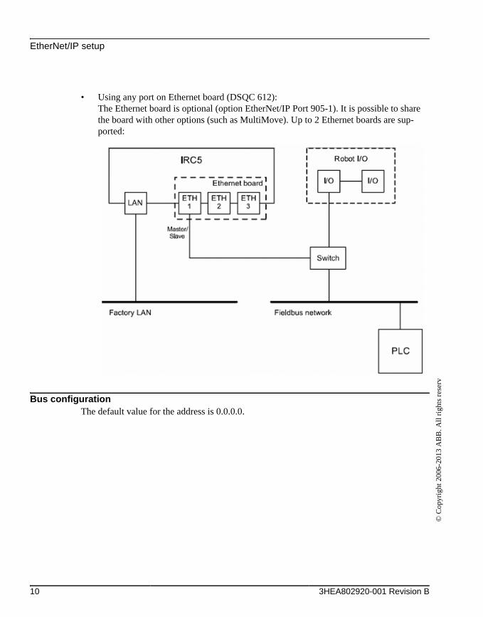
• Using any port on Ethernet board (DSQC 612): The Ethernet board is optional (option EtherNet/IP Port 905-1). It is possible to share the board with other options (such as MultiMove). Up to 2 Ethernet boards are sup-ported:
Bus configurationThe default value for the address is 0.0.0.0.
10 3HEA802920-001 Revision B

EtherNet/IP setup©
Cop
yrig
ht 2
006-
2013
AB
B. A
ll r
ight
s re
serv
ed.
LAN
3HEA802920-001 Revision B 11
EtherNet/IP setup
© C
opyr
ight
200
6-20
13 A
BB
. All
rig
hts
rese
rved
.
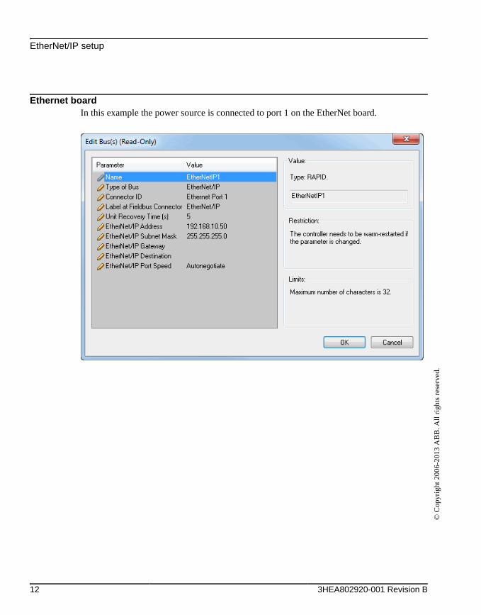
Ethernet boardIn this example the power source is connected to port 1 on the EtherNet board.
12 3HEA802920-001 Revision B
EtherNet/IP setup©
Cop
yrig
ht 2
006-
2013
AB
B. A
ll r
ight
s re
serv
ed.
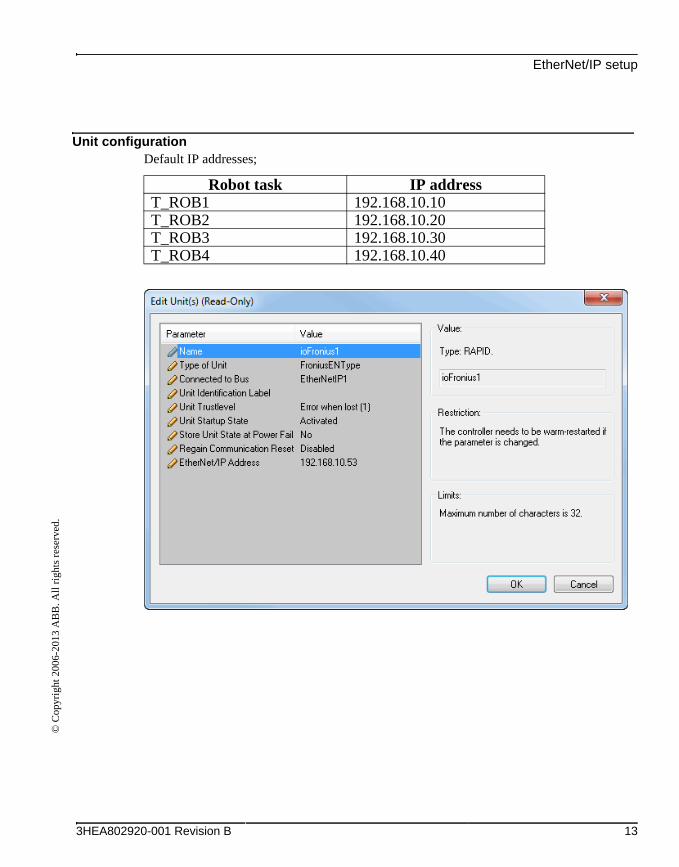
Unit configurationDefault IP addresses;
Robot task IP addressT_ROB1 192.168.10.10T_ROB2 192.168.10.20T_ROB3 192.168.10.30T_ROB4 192.168.10.40
3HEA802920-001 Revision B 13
Fronius welding equipment description
© C
opyr
ight
200
6-20
13 A
BB
. All
rig
hts
rese
rved
.
2.1.3 Fronius welding equipment description
GeneralThe TPS and TS welding machines are totally digitized, microprocessor-controlled inverter power sources. An interactive power source manager is coupled with a digital signal proces-sor, and together they control and regulate the entire welding process. The actual data is mea-sured continuously, and the machine responds quickly to changes. The control algorithms developed by Fronius ensure that the specified welding target is maintained. This helps make the welding process stable and repeatable.
Fronius Robotics Welding Products• Welding Power Source (TPS/TS 4000 and 5000)
• Wire feed Systems (VR1500)
• Data Documentation (Jobexplorer and Weld Office)
• Push Pull Welding Torches (Robacta Drive)
• Remote Control Units (RCU 4000 and 5000)
• Interface (Bus Systems and standard discrete)
Technical dataSee documentation from Fronius.
14 3HEA802920-001 Revision B

Software©
Cop
yrig
ht 2
006-
2013
AB
B. A
ll r
ight
s re
serv
ed.
2.2 Software
2.2.1 Software requirements
System prerequisites• IRC5 controller
DeviceNet• RobotWare 5.07.01 or higher
• Options [633-1] Arc
• Sub-option [650-9] Fronius TPS4000/5000
3HEA802920-001 Revision B 15

Software requirements
© C
opyr
ight
200
6-20
13 A
BB
. All
rig
hts
rese
rved
.
EtherNet/IP• RobotWare 5.14 or higher
• Option [633-1] Arc and Additional Option “Fronius TPS Integrated”.
• Option [650-11] External option loaded Welder has to be selected in the System Builder.
16 3HEA802920-001 Revision B
Process settings©
Cop
yrig
ht 2
006-
2013
AB
B. A
ll r
ight
s re
serv
ed.
3 Process settings
3.1 DeviceNet
OverviewThe Fronius Equipment Class and settings are activated if the following Power Source type is selected from the System Builder in RobotStudio.
• Power Source option 650-9 Fronius TPS 4000/5000This option has advanced support for the Fronius TPS 4000/5000 Power Source that includes:
• Support for three welding modes:
1. Job Mode
2. Job Mode with Correction
3. Program Mode
• Error code presentation on GTPU of errors originating from Group Output signal from Power Source.
3HEA802920-001 Revision B 17

Fronius Equipment Properties
© C
opyr
ight
200
6-20
13 A
BB
. All
rig
hts
rese
rved
.
3.1.1 Fronius Equipment Properties
The Fronius Equipment Properties can be defined in RW Arc.
Parameter Data type Note/illustration
Name string The name of the Fronius Equipment Properties
Use Equipment Standard IO string The name of the Equipment Standard IO to use
Use Fronius Equipment IO string The name of the Fronius Equipment IO to use
Mode string The mode of the welder.
The following modes are selectable:
• ProgramMode
• JobMode
• JobMode with Correction
• Default value: JobMode with Correction
Ignition on bool Specifies if ignition data specified in seamdata is to be used at the start of the weld phase. At the start it is often beneficial to define higher weld data values for a better ignition.If the ignition data parameter is changed, the contents of seamdata will also change.
Default value: FALSE
Heat on bool When the arc is ignited, the seam will generally not have reached the correct temperature. Preheating can thus be used at the start of the weld to define higher weld data values. The values to be used are. If the preheating parameter is changed, the contents of seamdata will also change.
Default value: FALSE
Heat as time bool Specifies if the heat phase should use the seam-
data parameters heat_time or heat_distance.
TRUE means that heat_time is used and visible
in the seamdata.
FALSE means that heat_distance and
heat_speed is used and visible in the seamdata.
Default value: FALSE
18 3HEA802920-001 Revision B

Fronius Equipment Properties©
Cop
yrig
ht 2
006-
2013
AB
B. A
ll r
ight
s re
serv
ed.
Cool time on bool Enables masking of cool_time component in seamdata.
Default value: TRUE
Fill on bool Specifies whether a crater fill is to be used in the final phase. This means that the end crater that can form in the completed weld will be filled in with extra filler material. If the Crater fill parameter is changed, the contents of seamdata will also change.Default value: FALSE
Arc Preset num Delays the power control signal with this time (seconds). This gives the analog reference signals and group output signals enough time to stabilise before the weld is started.
Default value: 0
Ignition timeout num The maximum time (in seconds) permitted for igniting the welding arc.
Default value: 1
Weld off timeout num The maximum time (in seconds) permitted for shutting off the welding arc.
Default value: 10
Auto inhibition on bool If this flag is set, weld inhibition will be allowed in AUTO mode, otherwise not allowed.
Default value: FALSE
Time to feed 15mm wire num The time in seconds to feed wire (15mm).
Default value: 1
Enable supervision on VC bool Enables signal supervision in the VC
Default value: FALSE
Parameter Data type Note/illustration
3HEA802920-001 Revision B 19

Arc Equipment Standard IO
© C
opyr
ight
200
6-20
13 A
BB
. All
rig
hts
rese
rved
.
3.1.2 Arc Equipment Standard IO
The Arc Equipment Standard IO signals can be defined in RW Arc.
Parameter Data type Note/illustration
Name string The name of the Arc Standard IO.
StopProc signaldi Digital input signal for stopping program execution. This signal affects arc welding instructions only. A high signal means that program execution will stop as soon as an arc welding instruction is executed.
ProcessStopped signaldo Digital output signal used to indicate that the weld has been interrupted. A high signal means that the weld has been interrupted either because of a welding defect or because of a normal program stop.
ManFeedInput signaldi Digital input signal for manual wire feed.
A high signal means that the welding equipment has manual wire feed enabled.
WeldInhib signaldi Digital input signal for program execution without welding.A high signal means that welding is inhibited.
WeaveInhib signaldi Digital input signal for program execution without weaving.A high signal means that weaving is inhibited.
TrackInhib signaldi Digital input signal to inhibit tracking. (Not seen on FlexPendant).A high signal means that the tracking is inhibited.
GunOk signaldi Digital input signal for supervision of the torch.A high signal means that the torch is OK.
SupervGun signaldo Digital output signal for indication of torch errors.A high signal means that an error has occurred.
AWError signaldo Digital output signal for indication of welding defects.A high signal means that an error has occurred. If a normal program stop occurs in the middle of a weld, no high signal will be generated.
20 3HEA802920-001 Revision B

Fronius Equipment IO©
Cop
yrig
ht 2
006-
2013
AB
B. A
ll r
ight
s re
serv
ed.
3.1.3 Fronius Equipment IO
The Fronius Equipment IO can be defined in RW Arc.
Parameter Data type Note/illustration
Name string The name of the Arc Equipment Analogue Inputs.
ArcEst DI (required) signaldi Digital input signal for supervision of the welding arc.A high signal means that the welding arc is ignited.
WaterOk DI signaldi Digital input signal for supervision of the water.A high signal means that the water is OK.
GasOk DI signaldi Digital input signal for supervision of the protective gas.A high signal means that the protective gas is OK.
Internal WirestickErr (required)
signaldi Digital input signal for supervision of the wire stick status.A high signal means that an error has occurred.
Internal WirestickON
(required)
signaldo Digital output signal to indicate wire stick errors.
WelderReady DI (required)
signaldi Digital input signal for WelderReady.
WelderCommOk DI (required)
signaldi Digital input signal for Welder Communication Ok.
Internal WelderReady DI
signaldi Internal digital input signal that indicates if the welder is ready
GasOn DO (required)
signaldo Digital output signal for control of the gas flow.A high signal means that the gas flow is active.
WeldOn DO (required)
signaldo Digital output signal for control of the weld voltage. A high signal means that the weld voltage control is active.
FeedOn DO (required)
signaldo Digital output signal for activation of the wire feed.A high signal means wirefeed forward.
FeedOnBwd DO (required)
signaldo Digital output signal for backward activation of the wire feed.A high signal means wirefeed backward.
RobotReady DO (required)
signaldo Digital output signal indicating RobotReady.
3HEA802920-001 Revision B 21

Fronius Equipment IO
© C
opyr
ight
200
6-20
13 A
BB
. All
rig
hts
rese
rved
.
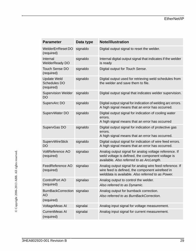
WelderErrReset DO (required)
signaldo Digital output signal to reset the welder.
Internal WelderReady DO
signaldo Internal digital output signal that indicates if the welder is ready
Touch Sense DO. (required)
signaldo Digital output for Touch Sense.
Update Weld Schedules DO (required)
signaldo Digital output used for retrieving weld schedules from the welder and save them to file.
Supervision Welder DO
signaldo Digital output signal that indicates welder supervision.
SupervArc DO signaldo Digital output signal for indication of welding arc errors. A high signal means that an error has occurred.
SupervWater DO signaldo Digital output signal for indication of cooling water errors. A high signal means that an error has occurred
SupervGas DO signaldo Digital output signal for indication of protective gas errors.A high signal means that an error has occurred.
SupervWireStick DO
signaldo Digital output signal for indication of wire feed errors.A high signal means that an error has occurred.
VoltReference AO (required)
signalao Analog output signal for analog voltage reference. If weld voltage is defined, the component voltage is available. Also referred to as ArcLength.
FeedReference AO (required)
signalao Analog output signal for analog wire feed reference.If wire feed is defined, the component wirefeed in welddata is available. Also referred to as Power.
ControlPort AO (required)
signalao Analog output to control the welder.
Also referred to as Dynamic.
BurnBackCorrection AO
(required)
signalao Analog output for burnback correction.
Also referred to as BurnBackCorrection.
VoltageMeas AI signalai Analog input signal for voltage measurement.
CurrentMeas AI
(required)
signalai Analog input signal for current measurement.
Parameter Data type Note/illustration
22 3HEA802920-001 Revision B

Fronius Equipment IO©
Cop
yrig
ht 2
006-
2013
AB
B. A
ll r
ight
s re
serv
ed.
SynWireFeed AI
(required)
signalai Analog input signal for synergic wirefeed.
MotorCurrentMeas AI
signalai Analog input signal for motor current measurements.
JobPort GO
(required)
signalgo Group output signal for sending the job number to the welder.
ProgramPort GO
(required)
signalgo Group output signal for sending the program number to the welder.
ModePort GO
(required)
signalgo Group output signal for sending the mode number to the welder.
WelderErrorCodes GI (required)
signalgi Group input signal for the error codes from the welder.
Parameter Data type Note/illustration
(required) means that the signal must be defined to be able to weld.
3HEA802920-001 Revision B 23
Fronius Weld Schedules
© C
opyr
ight
200
6-20
13 A
BB
. All
rig
hts
rese
rved
.
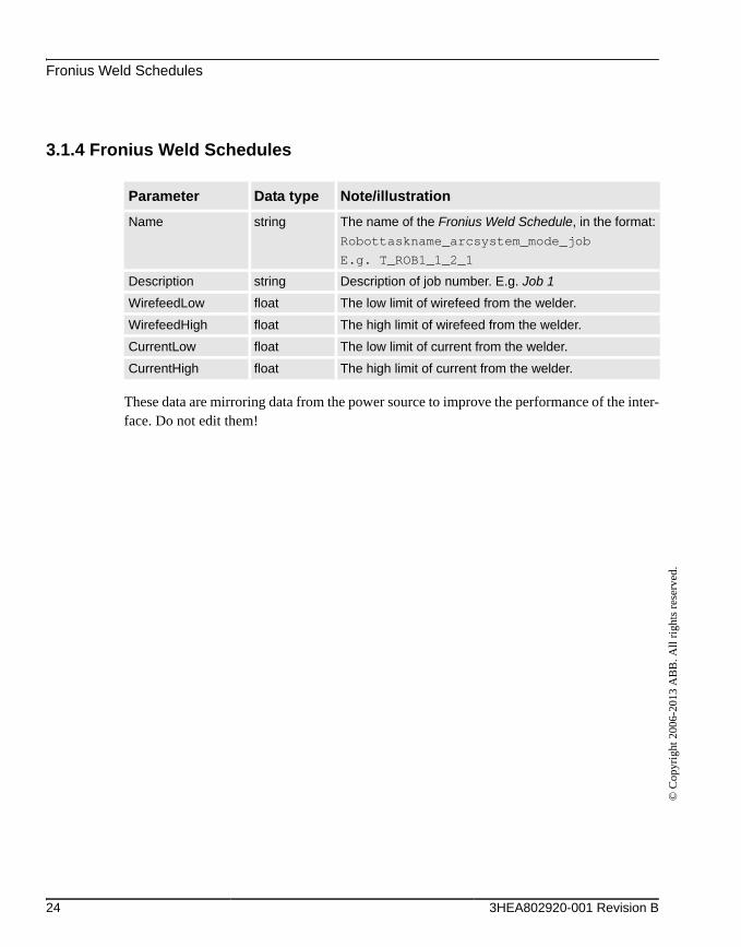
3.1.4 Fronius Weld Schedules
These data are mirroring data from the power source to improve the performance of the inter-face. Do not edit them!
Parameter Data type Note/illustration
Name string The name of the Fronius Weld Schedule, in the format:
Robottaskname_arcsystem_mode_job
E.g. T_ROB1_1_2_1
Description string Description of job number. E.g. Job 1
WirefeedLow float The low limit of wirefeed from the welder.
WirefeedHigh float The high limit of wirefeed from the welder.
CurrentLow float The low limit of current from the welder.
CurrentHigh float The high limit of current from the welder.
24 3HEA802920-001 Revision B

EtherNet/IP©
Cop
yrig
ht 2
006-
2013
AB
B. A
ll r
ight
s re
serv
ed.
3.1.5 EtherNet/IP
Fronius Arc Equipment Properties
Parameter Data type Note/illustration
Name string The name of the Fronius Equipment Properties
Use Equipment Standard IO string The name of the Equipment Standard IO to use
Use Fronius Equipment IO string The name of the Fronius Equipment IO to use
Mode string The mode of the welder.
The following modes are selectable:
• ProgramMode
• JobMode
• JobMode with Correction
• Default value: JobMode with Correction
Ignition on bool Specifies if ignition data specified in seamdata is to be used at the start of the weld phase. At the start it is often beneficial to define higher weld data values for a better ignition.If the ignition data parameter is changed, the contents of seamdata will also change.
Default value: FALSE
Heat on bool When the arc is ignited, the seam will generally not have reached the correct temperature. Preheating can thus be used at the start of the weld to define higher weld data values. The values to be used are. If the preheating parameter is changed, the contents of seamdata will also change.
Default value: FALSE
Heat as time bool Specifies if the heat phase should use the seam-
data parameters heat_time or heat_distance.
TRUE means that heat_time is used and visible
in the seamdata.
FALSE means that heat_distance and
heat_speed is used and visible in the seamdata.
Default value: FALSE
3HEA802920-001 Revision B 25

EtherNet/IP
© C
opyr
ight
200
6-20
13 A
BB
. All
rig
hts
rese
rved
.
Cool time on bool Enables masking of cool_time component in seamdata.
Default value: TRUE
Fill on bool Specifies whether a crater fill is to be used in the final phase. This means that the end crater that can form in the completed weld will be filled in with extra filler material. If the Crater fill parameter is changed, the contents of seamdata will also change.Default value: FALSE
Arc Preset num Delays the power control signal with this time (seconds). This gives the analog reference signals and group output signals enough time to stabilise before the weld is started.
Default value: 0
Ignition timeout num The maximum time (in seconds) permitted for igniting the welding arc.
Default value: 1
Weld off timeout num The maximum time (in seconds) permitted for shutting off the welding arc.
Default value: 10
Override On bool Not used
Auto inhibition on bool If this flag is set, weld inhibition will be allowed in AUTO mode, otherwise not allowed.
Default value: FALSE
Time to feed 15mm wire num The time in seconds to feed wire (15mm).
Default value: 1
Enable supervision on VC bool Enables signal supervision in the VC
Default value: FALSE
Parameter Data type Note/illustration
26 3HEA802920-001 Revision B

EtherNet/IP©
Cop
yrig
ht 2
006-
2013
AB
B. A
ll r
ight
s re
serv
ed.
Arc Equipment Standard IO.
Parameter Data type Note/illustration
Name string The name of the Arc Standard IO.
StopProc signaldi Digital input signal for stopping program execution. This signal affects arc welding instructions only. A high signal means that program execution will stop as soon as an arc welding instruction is executed.
ProcessStopped signaldo Digital output signal used to indicate that the weld has been interrupted. A high signal means that the weld has been interrupted either because of a welding defect or because of a normal program stop.
ManFeedInput signaldi Digital input signal for manual wire feed.
A high signal means that the welding equipment has manual wire feed enabled.
WeldInhib signaldi Digital input signal for program execution without welding.A high signal means that welding is inhibited.
WeaveInhib signaldi Digital input signal for program execution without weaving.A high signal means that weaving is inhibited.
TrackInhib signaldi Digital input signal to inhibit tracking. (Not seen on FlexPendant.)A high signal means that the tracking is inhibited.
GunOk signaldi Digital input signal for supervision of the torch.A high signal means that the torch is OK.
SupervGun signaldo Digital output signal for indication of torch errors. A high signal means that an error has occurred.
AWError signaldo Digital output signal for indication of welding defects.A high signal means that an error has occurred. If a normal program stop occurs in the middle of a weld, no high signal will be generated.
3HEA802920-001 Revision B 27

EtherNet/IP
© C
opyr
ight
200
6-20
13 A
BB
. All
rig
hts
rese
rved
.
Fronius Equipment IO
Parameter Data type Note/illustration
Name string The name of the Arc Equipment Analogue Inputs.
ArcEst DI (required) signaldi Digital input signal for supervision of the welding arc. A high signal means that the welding arc is ignited.
ArcEstLabel string Arc Supervision level: may have the values “MINOR”, “MAJOR” or “INFO”
WaterOk DI signaldi Digital input signal for supervision of the water.A high signal means that the water is OK.
GasOk DI signaldi Digital input signal for supervision of the protective gas.A high signal means that the protective gas is OK.
Internal WirestickErr (required)
signaldi Digital input signal for supervision of the wire stick status.A high signal means that an error has occurred.
Internal WirestickON
(required)
signaldo Digital output signal to indicate Wirestick errors.
WelderReady DI (required)
signaldi Digital input signal for WelderReady.
WelderCommOk DI (required)
signaldi Digital input signal for Welder Communication Ok.
Internal WelderReady DI
signaldi Internal digital input signal that indicates if the welder is ready
GasOn DO (required)
signaldo Digital output signal for control of the gas flow.A high signal means that the gas flow is active.
WeldOn DO (required)
signaldo Digital output signal for control of the weld voltage. A high signal means that the weld voltage control is active.
FeedOn DO (required)
signaldo Digital output signal for activation of the wire feed.A high signal means wirefeed forward.
FeedOnBwd DO (required)
signaldo Digital output signal for backward activation of the wire feed.A high signal means wirefeed backward.
RobotReady DO (required)
signaldo Digital output signal indicating RobotReady.
28 3HEA802920-001 Revision B
EtherNet/IP©
Cop
yrig
ht 2
006-
2013
AB
B. A
ll r
ight
s re
serv
ed.
WelderErrReset DO (required)
signaldo Digital output signal to reset the welder.
Internal WelderReady DO
signaldo Internal digital output signal that indicates if the welder is ready
Touch Sense DO (required)
signaldo Digital output for Touch Sense.
Update Weld Schedules DO (required)
signaldo Digital output used for retrieving weld schedules from the welder and save them to file.
Supervision Welder DO
signaldo Digital output signal that indicates welder supervision.
SupervArc DO signaldo Digital output signal for indication of welding arc errors. A high signal means that an error has occurred.
SupervWater DO signaldo Digital output signal for indication of cooling water errors. A high signal means that an error has occurred
SupervGas DO signaldo Digital output signal for indication of protective gas errors.A high signal means that an error has occurred.
SupervWireStick DO
signaldo Digital output signal for indication of wire feed errors.A high signal means that an error has occurred.
VoltReference AO (required)
signalao Analog output signal for analog voltage reference. If weld voltage is defined, the component voltage is available. Also referred to as ArcLength.
FeedReference AO (required)
signalao Analog output signal for analog wire feed reference. If wire feed is defined, the component wirefeed in welddata is available. Also referred to as Power.
ControlPort AO (required)
signalao Analog output to control the welder.
Also referred to as Dynamic.
BurnBackCorrection AO
(required)
signalao Analog output for burnback correction.
Also referred to as BurnBackCorrection.
VoltageMeas AI signalai Analog input signal for voltage measurement.
CurrentMeas AI
(required)
signalai Analog input signal for current measurement.
Parameter Data type Note/illustration
3HEA802920-001 Revision B 29

EtherNet/IP
© C
opyr
ight
200
6-20
13 A
BB
. All
rig
hts
rese
rved
.
Fronius Weld Schedules
These data are mirroring data from the power source to improve the performance of the inter-face. You should not edit them!
SynWireFeed AI
(required)
signalai Analog input signal for synergic wirefeed.
MotorCurrentMeas AI
signalai Analog input signal for motor current measurements.
JobPort GO
(required)
signalgo Group output signal for sending the job number to the welder.
ProgramPort GO
(required)
signalgo Group output signal for sending the program number to the welder.
ModePort GO
(required)
signalgo Group output signal for sending the mode number to the welder.
WelderErrorCodes GI (required)
signalgi Group input signal for the error codes from the welder.
Parameter Data type Note/illustration
Name string The name of the Fronius Weld Schedule, in the format:
Robottaskname_arcsystem_mode_job
E.g. T_ROB1_1_2_1
Schedule Name string Name of the job. E.g. Job 1
Description string Description of job number. E.g. Job 1
Settings float Internal data
Settings2 float Internal data
Wire Size float The size of the wire used in the job.
Parameter Data type Note/illustration
30 3HEA802920-001 Revision B
Fronius interface modes©
Cop
yrig
ht 2
006-
2013
AB
B. A
ll r
ight
s re
serv
ed.
4 Fronius interface modes
4.1 Overview
4.1.1 General
The Fronius TPS 4000 / 5000 welder has three interface modes that can be used depending on the welding application. The welddata components will automatically be customized to the selected interface mode. See the following chapters for more information.
Job Mode: The welding parameters (with the exception of pre flow, post flow, and purge time) are stored and set in the power supply using jobs. The job number (0-99) is set in the Weld Data.
Job Mode with Correction: The welding parameters are stored and set in the power supply (with the exception of pre-flow, post-flow, and purge time). Corrections can be made to the arc length, wire feed speed, and the pulse power/dynamic in the Weld Data. The job number (0-99) is set in the weld data.
Program Mode: All of the welding parameters are set and stored in the robot controller. The program (also known as a synergic line or a wave form) is stored in the power supply. The program is selected in the Weld Data and all of the welding parameters are set in the Seam and Weld Data. This interface allows the operator to make all weld settings from the FlexPendant rather than the power supply.
3HEA802920-001 Revision B 31
Set interface mode
© C
opyr
ight
200
6-20
13 A
BB
. All
rig
hts
rese
rved
.
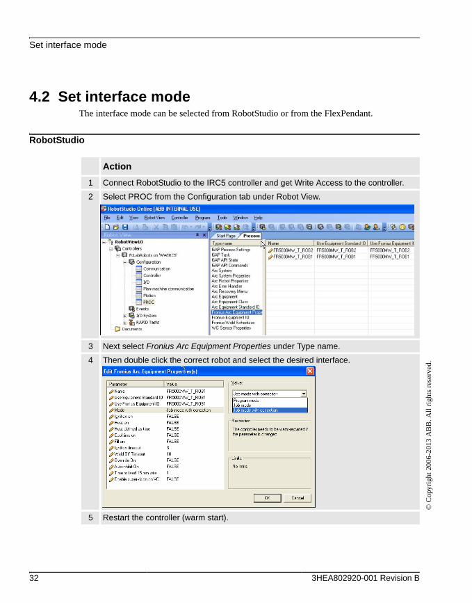
4.2 Set interface mode The interface mode can be selected from RobotStudio or from the FlexPendant.
RobotStudio
Action
1 Connect RobotStudio to the IRC5 controller and get Write Access to the controller.
2 Select PROC from the Configuration tab under Robot View.
3 Next select Fronius Arc Equipment Properties under Type name.
4 Then double click the correct robot and select the desired interface.
5 Restart the controller (warm start).
32 3HEA802920-001 Revision B

Set interface mode©
Cop
yrig
ht 2
006-
2013
AB
B. A
ll r
ight
s re
serv
ed.
FlexPendant
Action
1 From the Control Panel select Configuration and then PROC from the topics tab.
2 Then select Fronius Arc Equipment Properties.
3 Next select the robot that needs to be edited.
4 Then select the interface Mode.
5 Restart the controller (warm start).
3HEA802920-001 Revision B 33
JobMode
© C
opyr
ight
200
6-20
13 A
BB
. All
rig
hts
rese
rved
.
4.3 JobMode
4.3.1 Weld Data Parameters
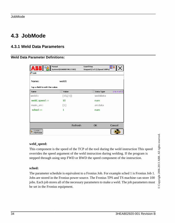
Weld Data Parameter Definitions:
weld_speed:
This component is the speed of the TCP of the tool during the weld instruction This speed overrides the speed argument of the weld instruction during welding. If the program is stepped through using step FWD or BWD the speed component of the instruction.
sched:
The parameter schedule is equivalent to a Fronius Job. For example sched 1 is Fronius Job 1. Jobs are stored in the Fronius power source. The Fronius TPS and TS machine can store 100 jobs. Each job stores all of the necessary parameters to make a weld. The job parameters must be set in the Fronius equipment.
34 3HEA802920-001 Revision B

JobMode with Correction©
Cop
yrig
ht 2
006-
2013
AB
B. A
ll r
ight
s re
serv
ed.
4.4 JobMode with Correction
4.4.1 Weld Data Parameters
Weld Data Parameter Definitions:
weld_speed:
This component is the speed of the TCP of the tool during the weld instruction. This speed overrides the speed argument of the weld instruction during welding. If the program is stepped through using step FWD or BWD the speed component of the instruction.
sched:
The parameter schedule is equivalent to a Fronius Job. For example sched 1 is Fronius Job 1. Jobs are stored in the Fronius power source. The Fronius TPS and TS machine can store 100 jobs. Each job stores all of the necessary parameters to make a weld. The job parameters must be set in the Fronius equipment.
3HEA802920-001 Revision B 35

Weld Data Parameters
© C
opyr
ight
200
6-20
13 A
BB
. All
rig
hts
rese
rved
.
voltage:
Arc-Length correction boundary for arc length upwards and downwards -30% to +30% of the value set for AL.1 in the power supply’s job. Example Al.1 in the Fronius Job is set to +10 and +30 (voltage) is set in your weld data. Your resultant value for Al.1 is 13.
Note: Arc Length Control must be set in the power supply for the voltage setting in the weld data to have an effect.
wirefeed:
Correction of the wirefeed speed. The range is -100 to 100. A value of 0 must be set if no correction to the wirefeed speed is wanted. This means that a wirefeed parameter of 100 will give you the maximum value of the Pch, and a wirefeed value of-100 will give you the lowest Pcl value.
Note: Pch and or Pcl must be set in the power-supply for the wirefeed setting in the weld data to have an effect.
Note: It is also possible set an actual wirefeed speed for the correction setting. Refer to sec-tion 4.3.2. the wirefeed value must fall in-between the PCH and PCL job setting.
Note: The default wirefeed units are in mm/sec. The wirefeed units can also be set in inches/min. Refer to section 4.4.3.
control:
Arc-force dynamic correction (constant voltage or synergic) or pulse correction (pulsed arc). The range is +5 to -5.
36 3HEA802920-001 Revision B

Changing the wirefeed Correction Settings©
Cop
yrig
ht 2
006-
2013
AB
B. A
ll r
ight
s re
serv
ed.
4.4.2 Changing the wirefeed Correction Settings
The Wirefeed Correction settings can be changed from Percentage to Wirefeed Speed by loading Fronius weld schedules and using them as jobs.
Step Action
1 Set the soFr1UpdateSched signal to high (1) from the Inputs and Outputs menu on the FlexPendant.
This will create a file @ Home/Arc/ConfigTemplates/FroniusTPS4K5K/ on the robot controller.
There will be one file for each welding robot.
E.g. FronWeldSched_T_ROB1_1.cfg for T_ROB1 and FronWeldSched_T_ROB2_1.cfg for T_ROB2.
2 Load the configuration files from either RobotStudio or from the FlexPendant.
Select Load parameters and replace duplicates.
3 Restart the controller (warm start).
4
The wirefeed speed parameter in weld data is now an actual speed, not a percentage value (%). The wirefeed speed must be set in the correct range. This range is set in the Fronius Synergic line.
3HEA802920-001 Revision B 37

Changing the wirefeed speed units
© C
opyr
ight
200
6-20
13 A
BB
. All
rig
hts
rese
rved
.
4.4.3 Changing the wirefeed speed units
The default units for wirefeed are in mm/s. The units can be changed to the desired units by selecting SI_UNITS, US_UNITS or WELD_UNITS in the ARC_SYSTEM parameters.
If wirefeed is setup as percentage, then the unit conversion will not work, so in this case SI_UNITS must be used.
38 3HEA802920-001 Revision B

ProgramMode©
Cop
yrig
ht 2
006-
2013
AB
B. A
ll r
ight
s re
serv
ed.
4.5 ProgramMode
4.5.1 Weld Data Parameters
Weld Data Parameter Definitions:
weld_speed:
This component is the speed of the TCP of the tool during the weld instruction This speed overrides the speed argument of the weld instruction during welding. If the program is stepped through using step FWD or BWD the speed component of the instruction.
sched:
The parameter schedule is equivalent to a Fronius Program. The Fronius power supply has Programs for many different types of materials, wire diameters, and transfer modes. The Pro-gram (also known as a synergic line or a wave form) is stored in the power supply. The range is 1 to 127.
3HEA802920-001 Revision B 39

Weld Data Parameters
© C
opyr
ight
200
6-20
13 A
BB
. All
rig
hts
rese
rved
.
mode:
The parameter mode has a range of 0 to 7, but for GMAW with Fronius Program mode only use the modes listed below.
0 = Synergic mode1 = Pulse (CC mode)4 = Constant Voltage (CV mode)
voltage:
This parameter is the same as arc length when welding in synergic mode or pulse. The range is -30 to +30. This parameter is voltage when welding in constant voltage mode. The range will vary depending on wire type and diameter.
wirefeed:
This parameter represents the command wirefeed speed in Program Mode.
The range is 0 to 100. A value of 50 must be set if no correction to the wirefeed speed is wanted. This means that a wirefeed parameter of 100 will give you the maximum value of the Pch, and a wirefeed value of 0 will give you the lowest Pcl value.
Note: Pch and or Pcl must be set in the power supply for the wirefeed setting in the weld data to have an effect.
Note: It is also possible set an actual wirefeed speed for the correction setting. Refer to sec-tion 4.3.2. the wirefeed value must fall in between the PCH and PCL job setting.
Note: The default wirefeed units are in mm/sec. The wirefeed units can also be set in inches/min. Refer to section 4.4.3.
control:
Arc-force dynamic correction (constant voltage or synergic) or pulse correction (pulsed arc). The range is +5 to -5.
40 3HEA802920-001 Revision B
Fronius Error codes©
Cop
yrig
ht 2
006-
2013
AB
B. A
ll r
ight
s re
serv
ed.
5 Fronius Error codes
5.1 Error codes
5.1.1 Fronius Error reporting
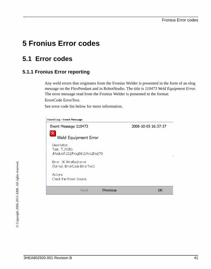
Any weld errors that originates from the Fronius Welder is presented in the form of an elog message on the FlexPendant and in RobotStudio. The title is 110473 Weld Equipment Error. The error message read from the Fronius Welder is presented in the format:
ErrorCode ErrorText.
See error code list below for more information.
3HEA802920-001 Revision B 41

Fronius Error Code List
© C
opyr
ight
200
6-20
13 A
BB
. All
rig
hts
rese
rved
.
5.1.2 Fronius Error Code List
42 3HEA802920-001 Revision B

Fronius Error Code List©
Cop
yrig
ht 2
006-
2013
AB
B. A
ll r
ight
s re
serv
ed.
3HEA802920-001 Revision B 43

Fronius Error Code List
© C
opyr
ight
200
6-20
13 A
BB
. All
rig
hts
rese
rved
.
44 3HEA802920-001 Revision B


3HE
A8
0292
0-00
1 R
ev B
, en
Contact us
ABB ABDiscrete Automation and MotionRobotics S-721 68 VÄSTERÅSSWEDENTelephone +46 (0) 21 344 400
www.abb.com