application guide for masterprotect galvanic protection · galvanic protection masterprotect ......
TRANSCRIPT
June 2018
Page 1 of 14
Application Guide for
MasterProtect® Cathodic & Galvanic Protection
MasterProtect® 815CP MasterProtect® 816CP MasterProtect® 810CP
MasterEmaco® N 5200CI MasterProtect® 8065, 8105 & 8160
June 2018
Page 2 of 14
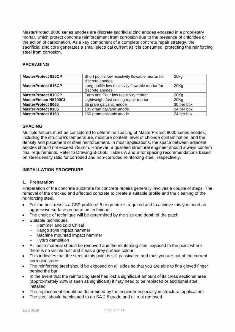
MasterProtect 8000 series anodes are discrete sacrificial zinc anodes encased in a proprietary mortar, which protect concrete reinforcement from corrosion due to the presence of chlorides or the action of carbonation. As a key component of a complete concrete repair strategy, the sacrificial zinc core generates a small electrical current as it is consumed, protecting the reinforcing steel from corrosion. PACKAGING MasterProtect 815CP Short potlife low resistivity flowable mortar for
discrete anodes 20kg
MasterProtect 816CP Long potlife low resistivity flowable mortar for discrete anodes
20Kg
MasterProtect 810CP Form and Pour low resistivity mortar 20Kg MasterEmaco N5200CI Lightweight fast setting repair mortar 20Kg MasterProtect 8065 65 gram galvanic anode 30 per box MasterProtect 8105 105 gram galvanic anode 24 per box MasterProtect 8160 160 gram galvanic anode 24 per box SPACING Multiple factors must be considered to determine spacing of MasterProtect 8000 series anodes, including the structure’s temperature, moisture content, level of chloride contamination, and the density and placement of steel reinforcement. In most applications, the space between adjacent anodes should not exceed 750mm. However, a qualified structural engineer should always confirm final requirements. Refer to Drawing B-1066, Tables A and B for spacing recommendations based on steel density ratio for corroded and non-corroded reinforcing steel, respectively. INSTALLATION PROCEDURE 1. Preparation Preparation of the concrete substrate for concrete repairs generally involves a couple of steps. The removal of the cracked and affected concrete to create a suitable profile and the cleaning of the reinforcing steel. • For the best results a CSP profile of 5 or greater is required and to achieve this you need an
aggressive surface preparation technique. • The choice of technique will be determined by the size and depth of the patch. • Suitable techniques
- Hammer and cold Chisel - Kango style impact hammer - Machine mounted impact hammer - Hydro demolition
• All loose material should be removed and the reinforcing steel exposed to the point where there is no visible rust and it has a grey surface colour.
• This indicates that the steel at this point is still passivated and thus you are out of the current corrosion zone.
• The reinforcing steel should be exposed on all sides so that you are able to fit a gloved finger behind the bar.
• In the event that the reinforcing steel has lost a significant amount of its cross sectional area (approximately 20% is seen as significant) it may need to be replaced or additional steel installed.
• The replacement should be determined by the engineer especially in structural applications. • The steel should be cleaned to an SA 2.5 grade and all rust removed.

June 2018
Page 3 of 14
• For small patches this can be done by wire brush and on larger jobs a needle gun, captive grit blasting will be effective.
• The action of the hydro demolition will clean the steel well and generally no further preparation would be necessary.
• The edges of the patch should be square cut to a depth of 10-20mm or as recommended by the individual product datasheet to prevent any of the repair mortar from being feather edged.
• Patches should be regular in shape and it may be necessary to join a number of small irregular patches to make a single regular patch.
• This will reduce the risk of cracking in the patch and the premature failure of the patch. • MasterProtect 8000 series Anode positioning should be considered when removing the existing
concrete. • For correct electrical connection and anode function, only structures using uncoated reinforcing
steel are suitable; the surface of the reinforcing steel should be untreated and cleaned to a shiny surface condition in areas designated for the connection of MasterProtect 8000 series Anodes.
• No other pre-treatment or post treatment of the steel is necessary. • Note: Reinforcing steel should be tested for continuity; that is, assuring that the reinforcements
are electrically connected by confirming that the DC resistance is ≤1Ω. Positioning • In most applications, the anodes should be positioned at the perimeter of the repair and on
plane with the reinforcing steel to provide a proper level of cover. • Anodes must be positioned so that the entire anode and the wire connections to the reinforcing
steel are totally covered by the encasement mortar once the repair is complete. • The anodes can be connected to a single bar or at a junction as shown. • Maintain the stand off from the bar created by the tie wires. • Performance can be compromised if this is not maintained.

June 2018
Page 4 of 14
Spacing of anodes depends on state of bars.
Table A Corroded Bars Steel Density Ratio Maximum Spacing mm
<0.20 700 0.21-0.40 600 0.41-0.54 500 0.55-0.67 450 0.68-0.80 400 0.8-0.94 375
0.95-1.07 350 1.08-1.20 325
Table A Non-Corroded Bars
Steel Density Ratio Maximum Spacing mm <0.30 750
0.31-0.60 700 0.61-0.90 650 0.91-1.20 550 1.21-1.50 500 1.51-2.00 425
• Connections to test continuity should be made using traditional techniques such as wire
ties or welded bonds. • Pre-wetting of MasterProtect 8000 series Anodes in clean water prior to encasement is
recommended for optimum adhesion of the encasement mortar.

June 2018
Page 5 of 14
Attaching • Tighten the two pairs of pre-twisted wires by hand around the reinforcing steel in a double wrap
pattern to achieve a sound electrical bond (see Photo 1). • The pre-twisted wire connectors provide a sound bond, good electrical contact and proper
spacing from the reinforcing steel to which the anode is attached. • No additional form of attachment or electrical connection is necessary or permitted.
Photo 1 Verification • Verify sound electrical connection of the anodes to the reinforcing steel by checking for a DC
resistance ≤1Ω (see Photo 2).
Photo 2
June 2018
Page 6 of 14
Repair mortar for bedding the anode • The anode should be encased in a low resistivity mortar to enhance its performance. • Suitable hand applied mortars are MasterEmaco N 5200CI and MasterEmaco S 5300CI. • In some instances, such as horizontal patches MasterProtect 815CP, 816CP and 810CP can
be used. • If MasterEmaco S 822 is used then no extra embedment mortar is necessary but care should
be taken to ensure that the shotcrete completely fills the cavity behind the anode and that the anode is not pushed out of place. These issues can be eliminated by the use of an embedment mortar.
• Corrosion protection is enhanced with low resistance repair mortars ≤20,000Ω - cm, and repair mortars that exceed 50,000Ω – cm may reduce the effectiveness of the anodes protection. Many design engineers have their own criteria and as an example GHD specify mortars within a range of 5000 to 50000 Ω-cm
• The mortars MasterEmaco N 5200CI or S 5300CI should be placed around the anode with a gloved hand and ensuring that the thickness of the mortar is at least 12mm.
• The MasterProtect 815CP, 816CP and 810CP are more liquid mixes and temporary formwork can be considered.
• A large scale repair using MasterProtect 810CP can be achieved without use of embedment mortars and the MasterProtect 810CP encasing the anodes and the surrounding steel work etc.
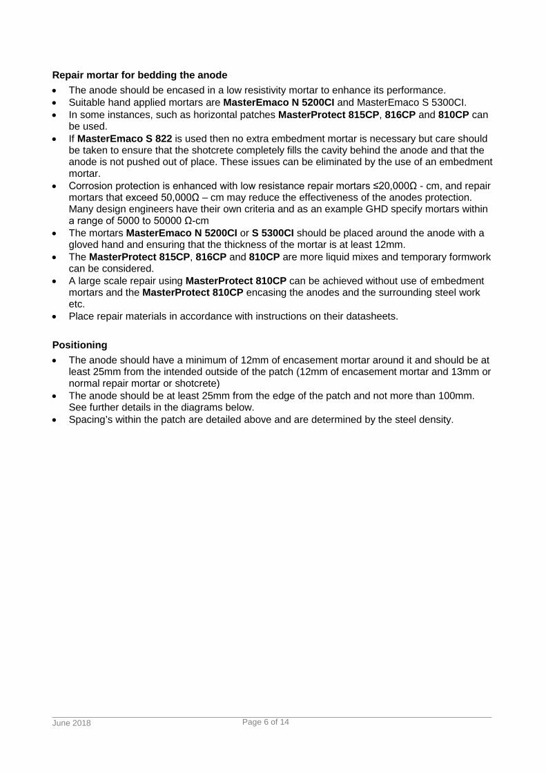
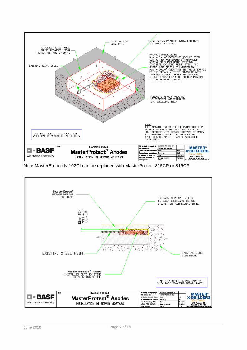
• Place repair materials in accordance with instructions on their datasheets. Positioning • The anode should have a minimum of 12mm of encasement mortar around it and should be at
least 25mm from the intended outside of the patch (12mm of encasement mortar and 13mm or normal repair mortar or shotcrete)
• The anode should be at least 25mm from the edge of the patch and not more than 100mm. See further details in the diagrams below.
• Spacing’s within the patch are detailed above and are determined by the steel density.
June 2018
Page 7 of 14
Note MasterEmaco N 102CI can be replaced with MasterProtect 815CP or 816CP

June 2018
Page 8 of 14
MONITORING • If the anode is correctly installed, the galvanic current it generates can be monitored over time. • This requires an externally mounted junction box with conduit leads connected to the
reinforcing steel and the anode. For further details on this option, please contact your local BASF sales representative during the project planning phase.
For details on mixing and application of the MasterEmaco repair mortars please see the MasterEmaco application guide and the individual datasheets. MasterProtect 815CP and 816CP (discrete anode application) Surface Preparation • These products are mostly used with discrete anodes. • A 30-40mm hole is drilled into the structure to the required depth and cleaned of dust etc by
washing or vacuuming. • The spacing of the holes, depth etc are determined by the engineer. Priming • No priming is necessary but for enhanced adhesion the hole should be pre-wetted.
June 2018
Page 9 of 14
Mixing and application (MasterProtect 815CP, 816CP) • Only full bags are mixed. Damaged or opened sacks should not be used. • Add mixing clean water to a clean mixing container. • Hold back approximately 10% of the water so that the consistency can be adjusted to the
required slump. • Mix mortars with a helical paddle attached to a slow speed (300-600 rpm) mixer or in a forced
action pan mixer for 3 minutes until a lump free, plastic to flowable consistency is achieved. • Add the remaining water until the required consistency is achieved. • The consistency will be determined by the application method MasterProtect 815CP and
816CP are often applied in a plastic state through a sealant gun with a large nozzle but also able to be mixed to a flowable consistency for filling vertical holes.
• Mixing water needed will vary depending on consistency required. See table for water addition ranges.
• Allow the mortar to rest for 2 - 3 minutes and then remix briefly, adjusting the consistency as required.
• In very hot weather the water demand will be at the high end of the range. MasterProtect 810CP (form and pour application) Mixing and application (MasterProtect 810CP) • Only full bags are mixed. Damaged or opened sacks should not be used. • Add mixing water to a clean mixing container. Hold back approximately 10% of the water so
that the consistency can be adjusted to the required slump. • Mix mortars with a helical paddle attached to a slow speed (300-600 rpm) mixer or in a forced
action pan mixer for 3 minutes until a lump free, flowable to fluid consistency is achieved. • Add the remaining water until the required consistency is achieved • Multi bag mixes can be done in hippo style mixes and in Putzmeister SP 11 pumps. • Pumping is preferable for large installations and the use of a tremmie tube can assist in
ensuring the cavity is completely filled. MasterProtect 815CP Plastic to flowable low
resistivity short potlife mortar 20kg 3.0-5.0L
MasterProtect 816CP Plastic to flowable low resistivity long potlife mortar
20Kg 2.5-3.6L (a creamy consistency is achieved around 2.7L)
MasterProtect 810CP Highly Flowable low resistivity form and pour mortar
20Kg 3.5-3.7L
Curing All cementitious materials will benefit from curing and if possible the use of a curing compound is advised. This is often impractical due to the requirement for the application of subsequent coatings and the use of wet hessian or plastic should be considered.

June 2018
Page 10 of 14
Figure 1 - Cleaning out behind the reinforcing
Figure 2 - Square cutting the edges of the patch
June 2018
Page 11 of 14
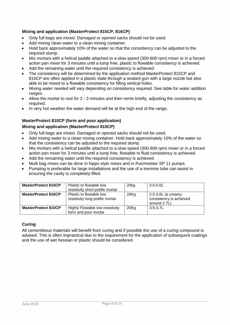
Figure 3 - Applying the MasterEmaco P 5000AP
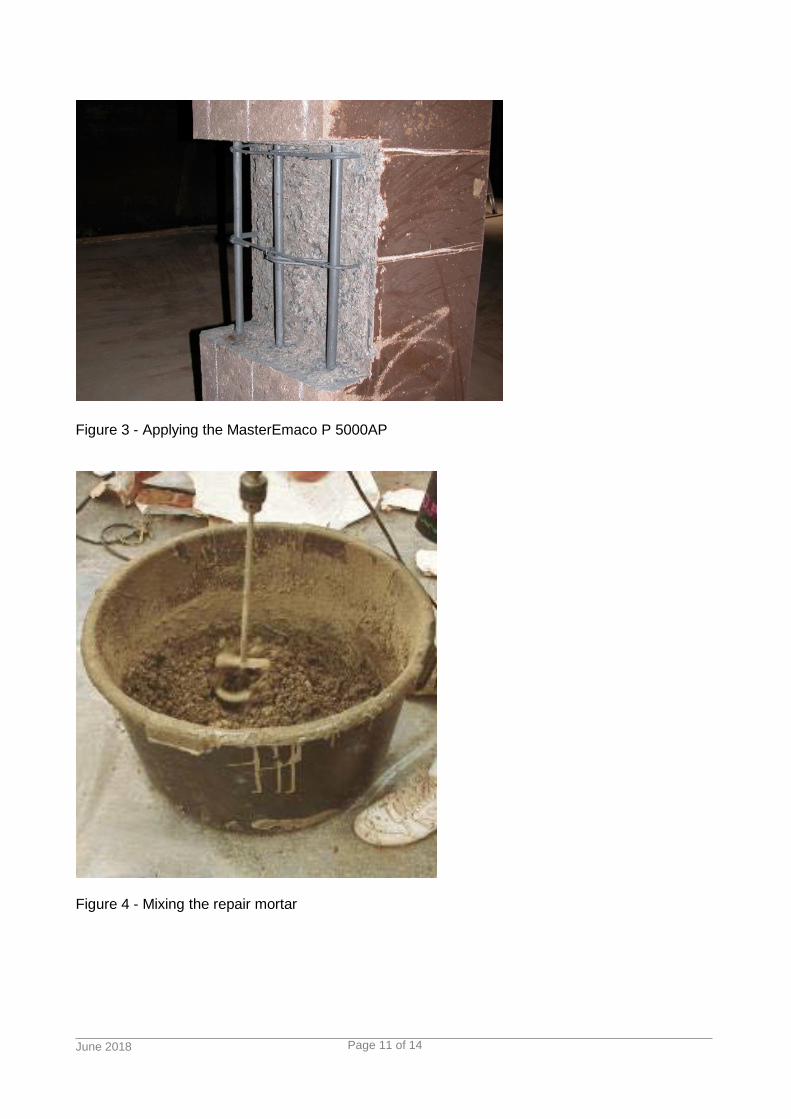
Figure 4 - Mixing the repair mortar

June 2018
Page 12 of 14
Figure 5 - Getting the required consistency
Figure 6 - An anode installed on new reinforcing
June 2018
Page 13 of 14
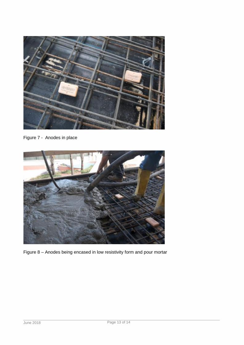
Figure 7 - Anodes in place
Figure 8 – Anodes being encased in low resistivity form and pour mortar

June 2018
Page 14 of 14
Figure 9 - Sealant gun with large nozzle for filling hole
Figure 10 Discrete Anode
Application Guide for MasterProtect Cathodic & Galvanic Protection V4 062018
STATEMENT OF RESPONSIBILITY
The technical information and application advice given in this BASF publication are based on the present state of our best scientific and practical knowledge. As the information herein is of a general nature, no assumption can be made as to a product's suitability for a particular use or application and no warranty as to its accuracy, reliability or completeness either expressed or implied is given other than those required by law. The user is responsible for checking the suitability of products for their intended use.
NOTE Field service where provided does not constitute supervisory responsibility. Suggestions made by BASF either orally or in writing may be followed, modified or rejected by the owner, engineer or contractor since they, and not BASF, are responsible for carrying out procedures appropriate to a specific application.
BASF Australia Ltd ABN 62008437867 Level 12 28 Freshwater Place Southbank VIC 3006 Freecall: 1300 227 300 www.master-builders-solutions.basf.com.au
BASF New Zealand Ltd Level 4, 4 Leonard Isitt Drive Auckland Airport 2022 Auckland, New Zealand Freecall: 0800 334 877 www.master-builders-solutions.basf.co.nz
BASF Emergency Advice: 1800 803 440 within Australia (24hr) 0800 944 955 within New Zealand