application for permit to drill
TRANSCRIPT
NorthSTAR User Manual
APD detailed info Version 3: 2.14.20
NorthSTAR Agency User Manual
Application for Permit to Drill
This manual contains detailed information on how to enter information into NorthStar based off operator’s documents. The permit which was utilized was approved by the NDIC Oil & Gas Division January 12, 2018. NDIC File No. 34478.
Operator InformationRequired to submit the NorthSTAR application.
NDIC Oil & Gas Division Staff verificationAgency will verify and correct as needed.

Step 3: Well Information
Note: You may fill in the Associated Bond (if known). The Associated Field Inspector may be found on our GIS Map Server. The Permit Fee is $100 for an APD.
{NDIC Pierre Top pick & Min Required Surface Casing are NDIC Oil & Gas Division Staff fields}
Step 3: Well Information Continued

The Multi-Well Pad Number is a NDIC Oil & Gas Division Staff field. The Magnetic Declination may be found at this web address: https://www.ngdc.noaa.gov/geomag/calculators/magcalc.shtml#declination
Step 4: Geologic Information

Note that although the applicant may request a waiver for Density/Porosity & Restivity on this form, a formal request must be made via NorthSTAR Sundry Notice. The director may consider waiving open hole logs based on viable logs wtihin one mile of the permitted well location.
*”YES” is the only acceptable answer on Cement Evaluation (required type) and Gamma to ground level (required type).
**“YES” or “Request Waiver” are acceptable answers on Density/Porosity (Required Type) or Resistivity (required type).
Step 4: Geologic Information Continued
The applicant must enter all geologic zones of significance.

*Minimum info required.


**Note: Zone Categories should basically indicate “Geologic Top” unless “Base of Last Salt”. In the case of BLS, the bottom TVD must be indicated.

Step 7: Features & Cement
It would be advisable to have all information ready at your disposal before starting this section, because the feature may “time out” after a certain amount non-use time. Also, it is a good practice to click “Save” for Step 7 after each section is completed.
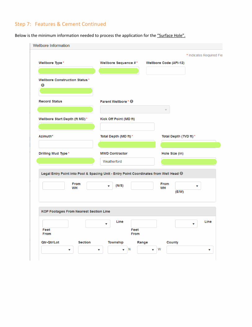
Step 7: Features & Cement Continued
Below is the minimum information needed to process the application for the “Surface Hole”.

Step 7: Features & Cement Continued
Below is the minimum information needed to process the application for the “Surface Hole”. There is no need to indicate the Bottom Hole Footages From Nearest Section, because the NDIC Oil & Gas Division does not allow intentional deviation of the surface hole. However we will not return the application if it is populated.
Step 7: Features & Cement Continued

Below is the minimum information needed to process the application for the “Vertical & Curve”.
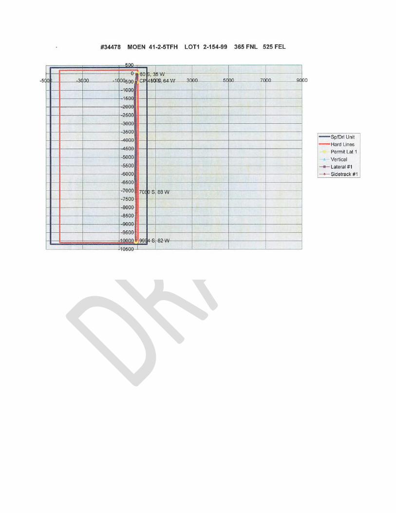
*Legal Entry Point into Pool & Spacing Unit: This info may be filled in by the operator, but is evaluated and corrected by Oil & Gas Division staff. It is an interpolated point between two survey stations. In this case, the well head is already at a legal point (with no back build)-so we need only be concerned with the Bakken Pool (strat limit: 50’ above the top of the Bakken). (This point will be verified by TLH or NHE).
*(pertaining to the directional plan above) Well head is legal with no back build, so we are compliant with the Spacing Unit setbacks. However, the legal entry point into the Bakken Pool is 50’ above the Upper Bakken Shale: 11,114’TVD minus 50’=11,1064’TVD; which is between 111060.73TVD and 11101TVD. We will use aformentioned TVD’s to get the coordinates for N/S & E/W.
Step 7: Features & Cement Continued

Below is the minimum information needed to process the application for the “Vertical & Curve”.
Step 7: Features & Cement Continued
Below is the minimum information needed to process the application for the “Vertical & Curve”. *The Bottom Hole Coordinates from Well Head indicate the End Of the Curve.

Based on the directional plan the EOC is:
Step 7: Features & Cement Continued
Below is the minimum info needed to process the Lateral “wellbore type”


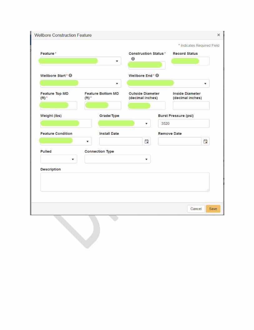

Wellbore Construction Feature: Casing. While it is preferred that the casing is segmented into Weight and Grade/Type, it is not required at this time. We will not return the permit if the weights and grade/types are combined into one record. However, make sure all the wells on the pad are consistently reporting the same info.


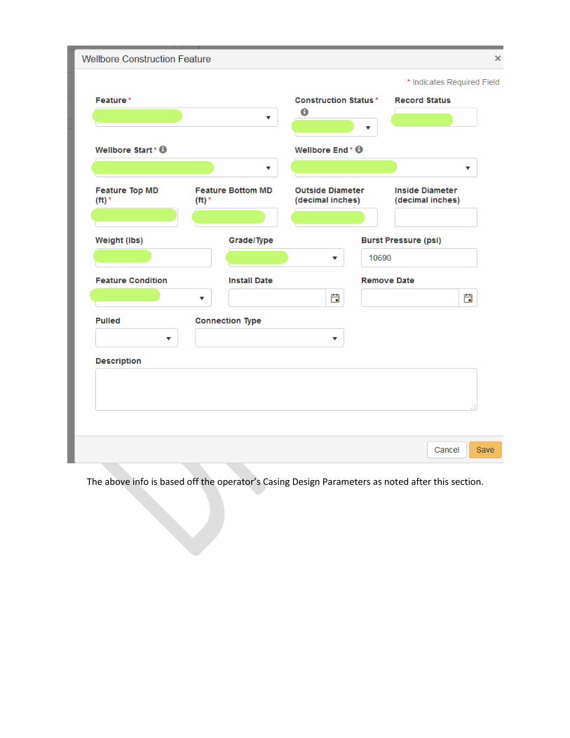
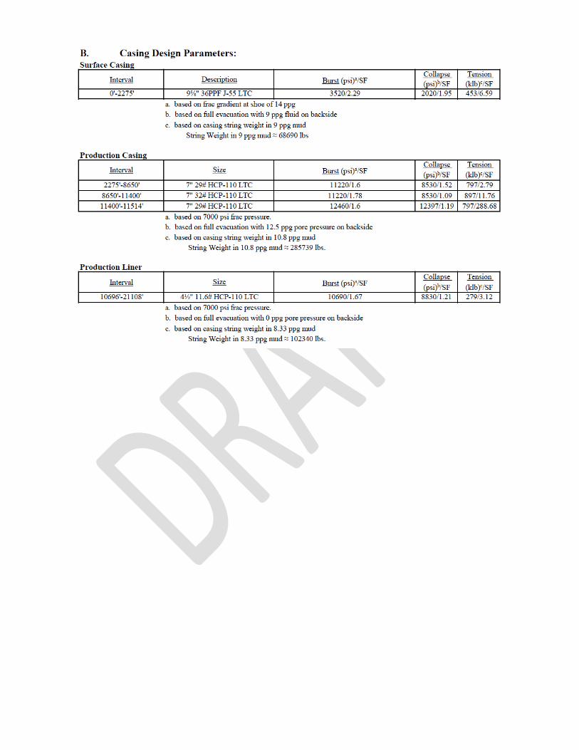
The above info is based off the operator’s Casing Design Parameters as noted after this section.
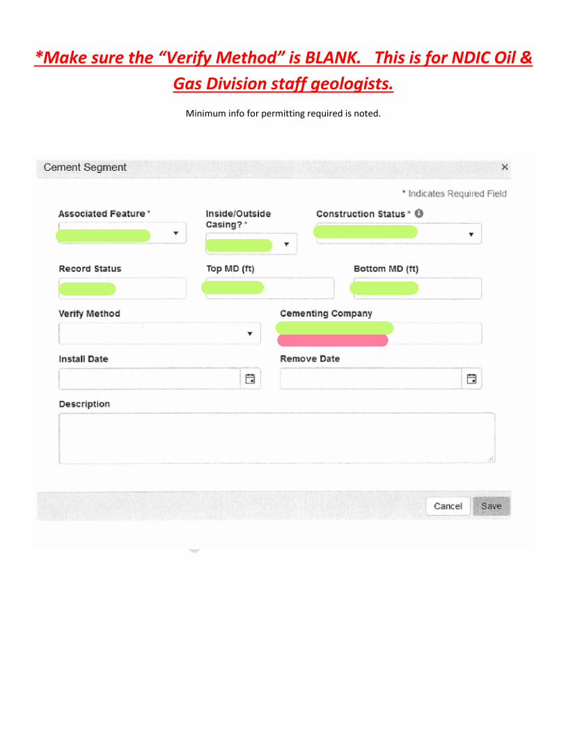
*Make sure the “Verify Method” is BLANK. This is for NDIC Oil & Gas Division staff geologists.
Minimum info for permitting required is noted.


Volume (sacks) are required. Ask that the operator fills out the Yield (cu ft per sack)


The above info is based off the operator’s Proposed Cementing Program as noted below.


Form Navigation 8 Note:
-If top the top coordinates of the completion interval (7” casing point-AKA production casing) are the same as Longstring Casing Point section, then there is no need to add them again.
-Note whether or not the surface reservation boundary is intersected by Spacing/Drilling Unit.
Typical “Bakken” single laterals: 7” (production) casing point will be the “top” of the completion interval, and bottom will be dependent upon the type toe isolation.
Examples include:
Wet shoe with the ability to frac out the shoe: Bottom completion coordinates would be the TD of the well.
Wet shoe with no ability to frac out the shoe: Bottom completion coordinates would be the closest proposed survey point to the location the Bridge Plug in the toe.
Cemented Liner with no ability to frac out the shoe: Bottom completion coordinate would be the top of the cemented shoe.

No Liner: Bottom completion coordinate would be the TD of the well.
Note: Enter the following info if it is known at the time of permitting: Perforation Diameter, Perforation Spacing & Number of shots. The information displayed is the minimum we would allow. We would prefer that the operator
indicate the top & bottom MD perforations. This information should be found on the Bakken Completion Schematic.

*This is extra space to explain the permit application. It may be used as a cover letter or otherwise it may remain blank.
It may also be used to indicate the deposition of the cuttings.
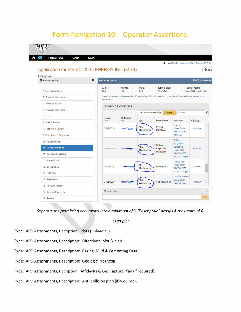
Form Navigation 10. Operator Assertions.
Separate the permitting documents into a minimum of 3 “Descriptive” groups & maximum of 6.
Example:
Type: APD Attachments, Decription: Plats (upload all).
Type: APD Attachments, Description: Directional plot & plan.
Type: APD Attachments, Description: Casing, Mud & Cementing Detail.
Type: APD Attachments, Description: Geologic Prognosis.
Type: APD Attachments, Decription: Affidavits & Gas Capture Plan (if required).
Type: APD Attachments, Description: Anti-collision plan (if required).

Form Navigation 11. Operator Assertions. Call the operator and discuss if there are
only one or two that appear incorrect. Send the form back if there appear to be multiple issues.

You may add a zero in the Water Appropriate Permit Number if it is NA.