application description 05/2015 clock synchronization ... · application description 05/2015 clock...
TRANSCRIPT

https://support.industry.siemens.com/cs/ww/en/view/69864408
Application description 05/2015
Clock Synchronization between a HMI Operator Panel and a SIMATIC PLC WinCC V13, Comfort Panels, S7-1200/S7-1500 und S7-300/S7-400 CPUs

Warranty and liability
S
iem
ens
AG 2
015
All r
ight
s re
serv
ed
Warranty and liability
Note The Application Examples are not binding and do not claim to be complete regarding the circuits shown, equipping and any eventuality. The Application Examples do not represent customer-specific solutions. They are only intended to provide support for typical applications. You are responsible for ensuring that the described products are used correctly. These application examples do not relieve you of the responsibility to use safe practices in application, installation, operation and maintenance. When using these Application Examples, you recognize that we cannot be made liable for any damage/claims beyond the liability clause described. We reserve the right to make changes to these Application Examples at any time without prior notice. If there are any deviations between the recommendations provided in these application examples and other Siemens publications – e.g. Catalogs – the contents of the other documents have priority.
We do not accept any liability for the information contained in this document.
Any claims against us – based on whatever legal reason – resulting from the use of the examples, information, programs, engineering and performance data etc., described in this Application Example shall be excluded. Such an exclusion shall not apply in the case of mandatory liability, e.g. under the German Product Liability Act (“Produkthaftungsgesetz”), in case of intent, gross negligence, or injury of life, body or health, guarantee for the quality of a product, fraudulent concealment of a deficiency or breach of a condition which goes to the root of the contract (“wesentliche Vertragspflichten”). The damages for a breach of a substantial contractual obligation are, however, limited to the foreseeable damage, typical for the type of contract, except in the event of intent or gross negligence or injury to life, body or health. The above provisions do not imply a change of the burden of proof to your detriment. Any form of duplication or distribution of these Application Examples or excerpts hereof is prohibited without the expressed consent of the Siemens AG.
Security informa-tion
Siemens provides products and solutions with industrial security functions that support the secure operation of plants, solutions, machines, equipment and/or networks. They are important components in a holistic industrial security concept. With this in mind, Siemens’ products and solutions undergo continuous development. Siemens recommends strongly that you regularly check for product updates.
For the secure operation of Siemens products and solutions, it is necessary to take suitable preventive action (e.g. cell protection concept) and integrate each component into a holistic, state-of-the-art industrial security concept. Third-party products that may be in use should also be considered. For more information about industrial security, visit http://www.siemens.com/industrialsecurity.
To stay informed about product updates as they occur, sign up for a product-specific newsletter. For more information, visit http://support.industry.siemens.com.
Clock Synchronization WinCC V13 (Basic/Comfort/Advanced) Entry-ID: 69864408, V1.3, 05/2015 2

Table of contents
S
iem
ens
AG 2
015
All r
ight
s re
serv
ed
Table of contents Warranty and liability ................................................................................................... 2
1 Task ..................................................................................................................... 5
1.1 Introduction ........................................................................................... 5 1.2 Overview of the automation task .......................................................... 5
2 Solution............................................................................................................... 6
2.1 Solution overview ................................................................................. 6 2.2 Description of the core functionality ..................................................... 7 2.3 Hardware and software components used........................................... 8
3 Basics ................................................................................................................. 9
3.1 HMI time synchronization mode ........................................................... 9 3.2 Area pointer ........................................................................................ 10 3.2.1 Date/time (operator panel → controller) ............................................. 11 3.2.2 Date/time PLC (controller→ operator panel) ...................................... 11 3.2.3 Control job .......................................................................................... 11 3.3 PLC clock blocks ................................................................................ 12 3.4 NTP time format ................................................................................. 12 3.5 “Date_And_Time” data format ............................................................ 13
4 Functional Mechanisms of this Application ................................................. 14
4.1 Area pointer setup .............................................................................. 14 4.1.1 Date/time (operator panel → controller) ............................................. 14 4.1.2 Date/time PLC (controller→ operator panel) ...................................... 14 4.1.3 Control job .......................................................................................... 15 4.2 PLC clock blocks ................................................................................ 17 4.2.1 Calling clock blocks ............................................................................ 17 4.2.2 RD_SYS_T: Reading time.................................................................. 17 4.2.3 WR_SYS_T: Setting time ................................................................... 18 4.2.4 RD_LOC_T: Reading local time ......................................................... 18 4.3 Data block “DB10_HMI_AreaPointer” (DB10) .................................... 19 4.4 Function block “FB110_TimeSyn_HMI_To_PLC” (FB110) ................ 20 4.5 Function block “FB120_TimeSyn_HMI_To_HMI” (FB120) ................ 23
5 Configuration and Settings............................................................................. 27
5.1 Project_01, “TimeSyn_Project_01” .................................................... 28 5.1.1 PLC program ...................................................................................... 28 5.1.2 HMI configuration ............................................................................... 29 5.2 Project_02, “TimeSyn_Project_02” .................................................... 36 5.2.1 PLC program ...................................................................................... 36 5.2.2 HMI configuration ............................................................................... 38 5.3 Project_03, “TimeSyn_Project_03” .................................................... 42 5.3.1 PLC program ...................................................................................... 42 5.3.2 HMI configuration ............................................................................... 45 5.4 Project_04, “TimeSyn_Project_04” .................................................... 50 5.4.1 PLC program ...................................................................................... 50 5.4.2 HMI configuration ............................................................................... 54
6 Operating the Application ............................................................................... 60
6.1 General information ............................................................................ 60 6.1.1 Calling the “Plant images” .................................................................. 61 6.1.2 Functionality of the plant screens ....................................................... 62 6.2 Project_01, TimeSyn_Project_01 ....................................................... 63 6.3 Project_02, TimeSyn_Project_02 ....................................................... 65 6.4 Project_03, TimeSyn_Project_03 ....................................................... 66
Clock Synchronization WinCC V13 (Basic/Comfort/Advanced) Entry-ID: 69864408, V1.3, 05/2015 3

Table of contents
S
iem
ens
AG 2
015
All r
ight
s re
serv
ed
6.5 Project_04, TimeSyn_Project_04 ....................................................... 67 7 Notes and Tips ................................................................................................. 68
7.1 Replacing PLC ................................................................................... 68 7.2 Changing HMI operator panel ............................................................ 68
8 Further notes, tips and tricks, etc. (optional) ............................................... 69 9 Related Literature ............................................................................................ 70
9.1 Bibliography ........................................................................................ 70 9.2 Internet links ....................................................................................... 70
10 History............................................................................................................... 71
Clock Synchronization WinCC V13 (Basic/Comfort/Advanced) Entry-ID: 69864408, V1.3, 05/2015 4

1 Task 1.1 Introduction
S
iem
ens
AG 2
015
All r
ight
s re
serv
ed
1 Task 1.1 Introduction
In order for components, such as, for example, HMI operator panels and SIMATIC controllers to work in a plant with identical time, one of the listed components has to be the timer for all other components. • The component acting as timer is called clock master. • The time receiving components are clock slaves. The application shows the respective options of clock synchronization and their implementation in the program. Select the clock synchronization you would like to use, based on the chapters.
1.2 Overview of the automation task
The figure below provides an overview of the automation task. Figure 1-1
Description of the automation task There are several HMI operator panels in a plant that exchange data with a SIMATIC controller. The following tasks are to be implemented: 1. In the first job, a HMI operator panel is to be the timer component (HMI
operator panel → SIMATIC controller). 2. In the second job, a SIMATIC controller is to be the timer component (SIMATIC
component → HMI operator panel).
Clock Synchronization WinCC V13 (Basic/Comfort/Advanced) Entry-ID: 69864408, V1.3, 05/2015 5
2 Solution 2.1 Solution overview
S
iem
ens
AG 2
015
All r
ight
s re
serv
ed
2 Solution 2.1 Solution overview
WinCC TIA Portal offers various solutions for the tasks described in chapter 1. The solutions depend on
• the SIMATIC controller. • used and the required clock synchronization. • used HMI operator devices.
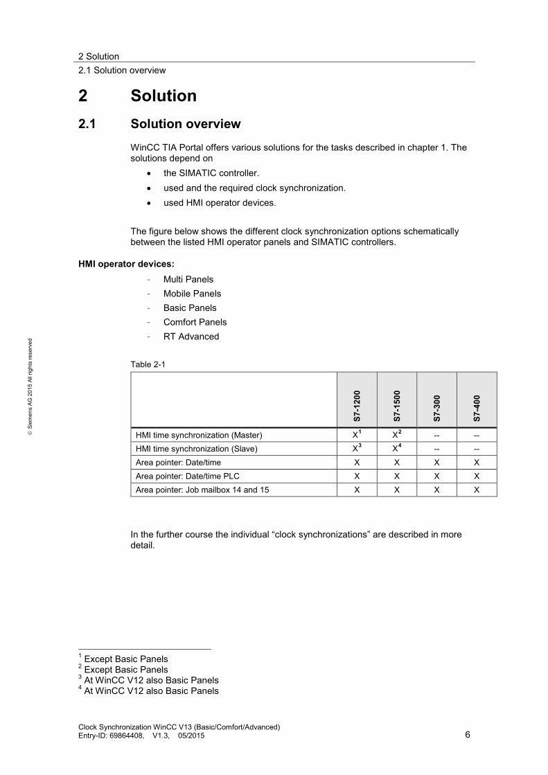
The figure below shows the different clock synchronization options schematically between the listed HMI operator panels and SIMATIC controllers.
HMI operator devices: – Multi Panels – Mobile Panels – Basic Panels – Comfort Panels – RT Advanced
Table 2-1
S7-1
200
S7-1
500
S7-3
00
S7-4
00
HMI time synchronization (Master) X1 X2 -- -- HMI time synchronization (Slave) X3 X4 -- -- Area pointer: Date/time X X X X Area pointer: Date/time PLC X X X X Area pointer: Job mailbox 14 and 15 X X X X
In the further course the individual “clock synchronizations” are described in more detail.
1 Except Basic Panels 2 Except Basic Panels 3 At WinCC V12 also Basic Panels 4 At WinCC V12 also Basic Panels
Clock Synchronization WinCC V13 (Basic/Comfort/Advanced) Entry-ID: 69864408, V1.3, 05/2015 6

2 Solution 2.2 Description of the core functionality
S
iem
ens
AG 2
015
All r
ight
s re
serv
ed
Delimitation This application does not include a description of… • the SIMATIC controller used • the HMI operator panels used • the configuration interface of WinCC V13 Basic knowledge of these topics is assumed. If required, please refer to the appropriate manuals (Link).
Required knowledge For the implementation of the clock synchronization via area pointer, basic knowledge of STEP 7 configuration is assumed.
2.2 Description of the core functionality
For the various clock synchronization options, an example project is included for each application. In the further course of the application the individual projects are described in detail. You can adjust the configurations to your wishes to your tasks or copy the respective blocks. The following types of clock synchronization are described. • Project_01 (includes two projects):
– HMI time synchronization (master). In this application the HMI operator panel is the timer component.
– HMI time synchronization (slave). In this application the SIMATIC controller is the timer component.
• Project_02: Area pointer: Date/Time. In this application the HMI operator panel is the timer component.
• Project_03: Area pointer: Date/Time PLC. In this application the SIMATIC controller is the timer component.
• Project_04: Area pointer: Control job 14 and 15. In this application the SIMATIC controller is the timer component, whereas the time and the date of the operator panel can be synchronized irrespective from each other with the PLC system time/date.
Clock Synchronization WinCC V13 (Basic/Comfort/Advanced) Entry-ID: 69864408, V1.3, 05/2015 7
2 Solution 2.3 Hardware and software components used
S
iem
ens
AG 2
015
All r
ight
s re
serv
ed
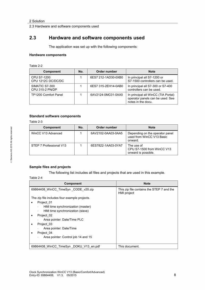
2.3 Hardware and software components used
The application was set up with the following components:
Hardware components
Table 2-2
Component No. Order number Note
CPU S7-1200 CPU 1212C DC/DC/DC
1 6ES7 212-1AD30-0XB0 In principal all S7-1200 or S7-1500 controllers can be used.
SIMATIC S7-300 CPU 315-2 PN/DP
1 6ES7 315-2EH14-0AB0 In principal all S7-300 or S7-400 controllers can be used.
TP1200 Comfort Panel 1 6AV2124-0MC01-0AX0 In principal all WinCC (TIA Portal) operator panels can be used. See notes in the docu.
Standard software components Table 2-3
Component No. Order number Note
WinCC V13 Advanced 1 6AV2102-0AA03-0AA5 Depending on the operator panel used from WinCC V13 Basic onward.
STEP 7 Professional V13 1 6ES7822-1AA03-0YA7 The use of CPU S7-1500 from WinCC V13 onward is possible.
Sample files and projects The following list includes all files and projects that are used in this example.
Table 2-4
Component Note
69864408_WinCC_TimeSyn _CODE_v20.zip The zip file includes four example projects. • Project_01
– HMI time synchronization (master) – HMI time synchronization (slave)
• Project_02 – Area pointer: Date/Time PLC
• Project_03 – Area pointer: Date/Time
• Project_04 – Area pointer: Control job 14 and 15
This zip file contains the STEP 7 and the HMI project
69864408_WinCC_TimeSyn _DOKU_V13_en.pdf This document.
Clock Synchronization WinCC V13 (Basic/Comfort/Advanced) Entry-ID: 69864408, V1.3, 05/2015 8
3 Basics 3.1 HMI time synchronization mode
S
iem
ens
AG 2
015
All r
ight
s re
serv
ed
3 Basics 3.1 HMI time synchronization mode
If a S7-1200 or S7-1500 controller is selected in the WinCC Engineering System as communication partner, then one of the following options can be selected in the connection settings under “HMI time synchronization mode”. • None: No clock synchronization is used. • Master: The operator panel specifies the time.
If several operator panels are used, one operator panel is configured as “master” and all other operator panels as “slave”.
• Slave: The controller specifies the time. For this type of clock synchronization no other configuration steps are required.
Properties of the clock synchronization • The operator panel can specify the time as master.
– In the "master mode" clock synchronization takes place every time a connection is established.
• The operator panel can accept the time from the controller as slave. – In the "slave mode" clock synchronization is carried out every time a
connection is established and then every 10 minutes. • The first clock synchronization is performed straight after the start of runtime
on the operator panel. • The clock synchronization is only performed during the operation or runtime on
the operator panel.
Restricting the clock synchronization Clock synchronization with the “HMI time synchronization mode” function can be configured with the following operator panels: • Basic Panels • TP177 4 • Multi Panel 177 • Multi Panel 277 • Multi Panel 377 • Mobile Panel 277 • Mobile 277 IWLAN V2 • Comfort Panels • Windows PC Systems with WinCC RT
Clock Synchronization WinCC V13 (Basic/Comfort/Advanced) Entry-ID: 69864408, V1.3, 05/2015 9

3 Basics 3.2 Area pointer
S
iem
ens
AG 2
015
All r
ight
s re
serv
ed
Restrictions during configuration • If several connections are configured to a SIMATIC S7-1200 or
SIMATIC S7-1500 for an operator panel, you can only configure one connection as “slave”.
• If you have enabled the clock synchronization for the operator panel as "slave", you can no longer use the "Date/time PLC" global area pointer.
• Basic Panels can only be configured as "slave". • If you are using basic panels for the configuration, unfortunately it is not
possible to simultaneously use clock synchronization via NTP and the "Date/time PLC" area pointer.
• If a controller is configured with protection type "complete protection", an operator panel can only poll the time, if the correct access password was configured on the operator panel. The access password for communication to a controller with protection class “complete protection” is configured in the “connections” editor of the operator panel. The access password has to match the configured password in the controller. The password for the controller is assigned in the properties of the controller under: “General > Protection”.
3.2 Area pointer The area pointers are centrally managed in the "Connections" editor and used for the exchange of data from certain user data areas. The area pointers are divided into two “groups”.
Area pointer • Coordination. • Date/Time. • Control job. • Data record. These are area pointers that can be enabled separately for each configured connection. This means that if a configuration has several controller connections, the “coordination” area pointer, for example, can be assigned to “Controller_1” as well as to “Controller_2” etc. at the same time.
Global area pointer of HMI device • Image number. • Date/Time PLC. • Project identification. These are area pointers that can explicitly only be assigned to one connection. This means that if a configuration has several controller connections, the “image number” area pointer, for example, can be either assigned to “Controller_1” or to “Controller_2” but not to both at the same time.
Clock Synchronization WinCC V13 (Basic/Comfort/Advanced) Entry-ID: 69864408, V1.3, 05/2015 10
3 Basics 3.2 Area pointer
S
iem
ens
AG 2
015
All r
ight
s re
serv
ed
3.2.1 Date/time (operator panel → controller)
The area pointer is used for the transmission of date and time from the operator panel to the controller. For the implementation of the task, the “control job” area pointer is required in addition. With the evaluation of control job “40” the operator panel writes the current date and time in the configured data area of the "Date/Time" area pointer. Details on establishing the data area can be found in chapter 4. Note: When you have configured the "date/time" area pointer you cannot use the "date/time PLC" area pointer.
3.2.2 Date/time PLC (controller→ operator panel)
The area pointer is used for the transmission of date and time from the controller to the operator panel. You are using this area pointer, when the controller is master for the time. The controller is loading the data area of the area pointer. The area pointer reads the data cyclically via the configured acquisition cycle and synchronizes itself. Notes: • Do not make the acquisition cycle too small.
Recommendation: Acquisition cycle ≥ 1 minute. (An acquisition cycle of 1 hour is usually enough).
• When you have configured the "date/time PLC" area pointer, you cannot use the "date/time" area pointer.
Details on establishing the data area can be found in chapter 4.
3.2.3 Control job
You can transfer control jobs via the control job compartment and thus trigger functions/actions on the operator panel. Among these functions are, e.g. setting the date and time. Note: In contrast to the “date/time PLC” area pointer, you can, for example, transfer the time and/or date separately from the controller to the operator panel by the control jobs 14 and 15.
Control job 14 The time from the controller to the operator device is transferred via control job 14. Details on establishing the control job compartment can be found in chapter 4.
Control job 15 The date from the controller to the operator device is transferred via control job 15. Details on establishing the control job compartment can be found in chapter 4.
Clock Synchronization WinCC V13 (Basic/Comfort/Advanced) Entry-ID: 69864408, V1.3, 05/2015 11

3 Basics 3.3 PLC clock blocks
S
iem
ens
AG 2
015
All r
ight
s re
serv
ed
Control job 40 Date and time are transferred from the operator panel to the controller via control job 40. Details on establishing the control job compartment can be found in chapter 4.
3.3 PLC clock blocks
System blocks used for setting and reading the PLC time In the application the following system blocks are used for reading or setting the CPU clock. • Reading local time "RD_LOC_T". • Reading time "RD_SYS_T". • Setting clock: "WR_SYS_T". Details for the setup are available in chapter 4. RD_LOC_T: Reading local time With the “RD_LOC_T” instruction the current local time is read out from the CPU clock. RD_SYS_T: Reading time With the "RD_SYS_T" instruction the current date and the current time is read out from the CPU clock. WR_SYS_T: Setting time By calling "WR_SYS_T" the time and the date of the CPU clock is set.
3.4 NTP time format
The NTP (network time protocol) is a general process for the synchronization of system clocks in local and global networks. With the NTP process, the interface of the CPU sends time requests at regular intervals (in client mode) to the NTP server in the subnet (LAN), whose addresses have to be configured. Based on the replies of the server, the most reliable and precise time is detected and synchronized. The advantage of this process is the possible clock synchronization across subnet boundaries. The precision depends on the quality of the NTP server used.
Clock Synchronization WinCC V13 (Basic/Comfort/Advanced) Entry-ID: 69864408, V1.3, 05/2015 12
3 Basics 3.5 “Date_And_Time” data format
S
iem
ens
AG 2
015
All r
ight
s re
serv
ed
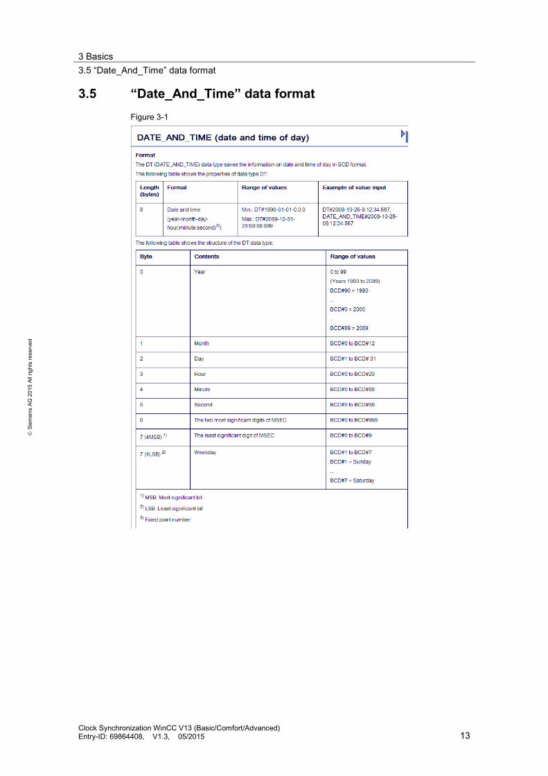
3.5 “Date_And_Time” data format Figure 3-1
Clock Synchronization WinCC V13 (Basic/Comfort/Advanced) Entry-ID: 69864408, V1.3, 05/2015 13

4 Functional Mechanisms of this Application 4.1 Area pointer setup
S
iem
ens
AG 2
015
All r
ight
s re
serv
ed
4 Functional Mechanisms of this Application Introduction
Below, detailed information regarding setup and data structure of the area pointer and the PLC system blocks used in the sample projects are described. This information can also be read in the online help or in the WinCC Advanced V13.0 system manual (Link). There is furthermore a description of the details on the data and program blocks to be created.
4.1 Area pointer setup
4.1.1 Date/time (operator panel → controller)
The data area date/time has the following setup: Figure 4-1
“Date_And_Time” is used as data type in the controller. For this purpose, look at the setup of the configured DB10 in chapter 4.3.
4.1.2 Date/time PLC (controller→ operator panel)
The data area date/time has the following setup: Figure 4-2
“Struct” is used as data type in the controller. For this purpose, look at the setup of the configured DB10 in chapter 4.3.
Clock Synchronization WinCC V13 (Basic/Comfort/Advanced) Entry-ID: 69864408, V1.3, 05/2015 14

4 Functional Mechanisms of this Application 4.1 Area pointer setup
S
iem
ens
AG 2
015
All r
ight
s re
serv
ed
4.1.3 Control job
The order number is in the first word of the control job compartment. Depending on the control job, up to three parameters can then be transmitted. Figure 4-3
When the first word of the control job compartment is not equal to 0, the operator panel evaluates the control job. This is why the parameters of the control job compartment (parameter 1 to parameter 3) have to be entered and only then the order number. If the operator panel has accepted the control job, the first word is reset to 0. At this time the execution of the control job is generally not yet completed. In the controller, “Array [0..3] of Word” is used as data type. For this purpose, look at the setup of the configured DB10 in chapter 4.3.
Control job 14 (order number) The time (BCD coded) is transmitted from the controller to the operator device with control job 14. Parameter control job 14 Figure 4-4
Clock Synchronization WinCC V13 (Basic/Comfort/Advanced) Entry-ID: 69864408, V1.3, 05/2015 15

4 Functional Mechanisms of this Application 4.1 Area pointer setup
S
iem
ens
AG 2
015
All r
ight
s re
serv
ed
Control job 15 (order number) The date (BCD coded) is transmitted from the controller to the operator device with control job 15. Parameter control job 15 Figure 4-5
Notes: • The KTP 600 BASIC PN operator panel ignores the day of the week. • If you are using the "date/time PLC" area pointer, the day of the week is
ignored.
Control job 40 (order number) The date (BCD coded) is transmitted from the controller to the operator device with control job 40. Parameter control job 40 Figure 4-6
Clock Synchronization WinCC V13 (Basic/Comfort/Advanced) Entry-ID: 69864408, V1.3, 05/2015 16

4 Functional Mechanisms of this Application 4.2 PLC clock blocks
S
iem
ens
AG 2
015
All r
ight
s re
serv
ed
4.2 PLC clock blocks
4.2.1 Calling clock blocks
The different clock functions can be found in the "Instructions" task card. The individual clock functions are listed under the "Extended instructions" palette. Figure 4-7
4.2.2 RD_SYS_T: Reading time
With the "RD_SYS_T" instruction, the current date and the current time is read out from the CPU clock. The read out data is output in DT format at the OUT output of the instruction. In the output value there are no details regarding the local time zone or summer time. At the RET_VAL output you can enquire whether errors occurred during the execution of the instruction. Figure 4-8
Clock Synchronization WinCC V13 (Basic/Comfort/Advanced) Entry-ID: 69864408, V1.3, 05/2015 17

4 Functional Mechanisms of this Application 4.2 PLC clock blocks
S
iem
ens
AG 2
015
All r
ight
s re
serv
ed
4.2.3 WR_SYS_T: Setting time
By calling "WR_SYS_T", you set the time and the date of the CPU clock. The clock then runs from the set time and the set date. Date and time is entered in the DT date format at the “IN” input of the instruction. To transfer the formats DATE and TOD into the required DT data format, you can use the "T_COMBINE" instruction. If the clock is a master clock, the CPU additionally starts the synchronization of the time when it is called. The synchronization intervals are set via configuration. Details on local time zone or summer time cannot be transmitted with the "WR_SYS_T" instruction. At the “RET_VAL” output you can enquire whether errors occurred during the execution of the instruction. Figure 4-9
4.2.4 RD_LOC_T: Reading local time
Read out the current local time from the CPU clock and output it at the “OUT” output with the “RD_LOC_T” instruction. To output the local time, the details on time zone as well as the start of the summer and winter time is used which you set when you configured the CPU clock. Figure 4-10
Clock Synchronization WinCC V13 (Basic/Comfort/Advanced) Entry-ID: 69864408, V1.3, 05/2015 18

4 Functional Mechanisms of this Application 4.3 Data block “DB10_HMI_AreaPointer” (DB10)
S
iem
ens
AG 2
015
All r
ight
s re
serv
ed
4.3 Data block “DB10_HMI_AreaPointer” (DB10)
DB10_HMI_AreaPointer The DB10 includes a summarization of the possible area pointer and their data areas. For the implementation of the clock synchronization not all of the listed area pointers are required. • "Coordination" area pointer (not used). • “Date/Time” area pointer • "Control job" area pointer. • "Data record" area pointer (not used). • "Project identification" area pointer (not used). • "Image number" area pointer (not used). • “Date/Time PLC” area pointer Figure 4-11
Clock Synchronization WinCC V13 (Basic/Comfort/Advanced) Entry-ID: 69864408, V1.3, 05/2015 19

4 Functional Mechanisms of this Application 4.4 Function block “FB110_TimeSyn_HMI_To_PLC” (FB110)
S
iem
ens
AG 2
015
All r
ight
s re
serv
ed
4.4 Function block “FB110_TimeSyn_HMI_To_PLC” (FB110)
Clock synchronization “Operator panel → Controller” Via the function block the clock synchronization is implemented via the area pointers
– “Date/Time” – “Control job”, with order number “40”.
The block includes the system function blocks – WR_SYS_T
(The time and the date of the CPU clock is set with the call). – RD_SYS_T
(With the "RD_SYS_T" instruction the current date and the current time is read out from the CPU clock).
The FB110 is used in the “TimeSyn_Project_03” project.
View of the "FB110" The “FB110” has an “input/output parameter” that is switched according to the specification. You can edit the FB if needed. By default the FB does not have to be edited. Figure 4-12
Clock Synchronization WinCC V13 (Basic/Comfort/Advanced) Entry-ID: 69864408, V1.3, 05/2015 20

4 Functional Mechanisms of this Application 4.4 Function block “FB110_TimeSyn_HMI_To_PLC” (FB110)
S
iem
ens
AG 2
015
All r
ight
s re
serv
ed
Function sequence FB110 Below the program sequence of FB110 is described. The program sequence is in the form of a step chain. Table 4-1
Network Comment
1 General: Copying values into the static area from the "Date/clock" area pointer. Via the “AreaPointer_DateTime” input parameter the content on the assigned “Date/time” area pointer is read in. The input parameter has the “Date_And_Time” data type. For the later evaluation of the clock synchronization it is required to divide the input parameter “by byte”. The result is copied in the data area of the static “Edited_AreaPointer_DateTime” tag. “AreaPointer_DateTime” → “Edited_AreaPointer_DateTime”.
2 Step 1: Start of the clock synchronization. Via the “SetTime” InOut parameter the “start signal” for enabling the clock synchronization is read in and read out. The InOut parameter has the “Bool” data type. The content of the “control job” area pointer is read in and out via the “AreaPointer_JobMailbox" InOut parameter. The input parameter has the “Array [0..3] of Word” data type. With the start of the clock synchronization the parameters 1 to 3 of the “control job” area pointer are preassigned with “0”.
3 Step 2: Save the current value from the date/time area pointer. The “Edited_AreaPointer_DateTime” tag is read out in the network and its content is divided and temporarily stored in the
– „SaveData_Previous_HMI_Time_01“ „SaveData_Previous_HMI_Time_02“
tags. Technical background: The “Edited_AreaPointer_DateTime” tag has the “Date_And_Time” data type, which corresponds to a length of 2 double words. In the further course, the tag is required for a “clock comparison”. In order to be able to compare the content of the tag with the “==D" instruction, the tag is divided into two individual double words.
Clock Synchronization WinCC V13 (Basic/Comfort/Advanced) Entry-ID: 69864408, V1.3, 05/2015 21

4 Functional Mechanisms of this Application 4.4 Function block “FB110_TimeSyn_HMI_To_PLC” (FB110)
S
iem
ens
AG 2
015
All r
ight
s re
serv
ed
Network Comment
4 Step 3: Execute control job "40". The “AreaPointer_JobMailbox” InOut parameter is transferred to “order number” 40. Note: The order number has to be specified in “hex format”.
5 Step 4: Evaluation, finish job "40". Via the “AreaPointer_JobMailbox" InOut parameter it is evaluated when the previously set control job “40” is reset to “0” by the operator panel. Note: If the operator panel has accepted the control job the control job is reset to “0”. At this time the execution of the control job is generally not yet completed.
6 Step 5: Evaluation, new HMI time accepted? The “Edited_AreaPointer_DateTime” static tag can be read out via the network and divided and temporarily stored in the following tags
– „SaveData_New_HMI_Time_01“ – „SaveData_New_HMI_Time_02“
Technical background: In order to detect that the control job has been fully completed, the network performs a time comparison. The control job is completed when the comparison of the tags ”SaveData_Previous_HMI_Time” and “SaveData_New_HMI_Time” are unequal.
7 Step 6: Transfer new HMI system time to the PLC. The PLC system time is synchronized with the system time of the operator panel via the network. For this purpose the “AreaPointer_DateTime” input parameter tag is assigned to the “IN Parameter” of the “WR_SYS_T” system function block.
8 General: Output of the current PLC time on the operator panel. The read out PLC system time is output via the “Current_PLCTime” output parameter tag. For this purpose the “Current_PLCTime” tag is assigned to the “OUT Parameter” of the “RD_SYS_T” system function block. The output parameter has the “Date_And_Time” data type.
Clock Synchronization WinCC V13 (Basic/Comfort/Advanced) Entry-ID: 69864408, V1.3, 05/2015 22

4 Functional Mechanisms of this Application 4.5 Function block “FB120_TimeSyn_HMI_To_HMI” (FB120)
S
iem
ens
AG 2
015
All r
ight
s re
serv
ed
4.5 Function block “FB120_TimeSyn_HMI_To_HMI” (FB120)
Clock synchronization “Controller→ Operator panel” Via the function block the time and the date of the HMI operator panel can be synchronized separately with the time of the PLC. The implementation of the clock synchronization is performed via the area pointer
– “Control job”, with order number “14” (time) – “Control job”, with order number “15” (date)
The FB120 is used in the “TimeSyn_Project_04” project.
View of the "FB120" The “FB120” has an “input/output parameter” that is switched according to the specification. You can edit the FB if needed. By default the FB does not have to be edited. Figure 4-13
Clock Synchronization WinCC V13 (Basic/Comfort/Advanced) Entry-ID: 69864408, V1.3, 05/2015 23

4 Functional Mechanisms of this Application 4.5 Function block “FB120_TimeSyn_HMI_To_HMI” (FB120)
S
iem
ens
AG 2
015
All r
ight
s re
serv
ed
Function sequence FB120 Below the program sequence of FB120 is described. The program sequence is in the form of a step chain. Table 4-2
Network Comment
1 General: Copying values into the temp area from the "control job" area pointer. The content of the “Control job” area pointer is read in via the “AreaPointer_JobMailbox" InOut parameter. The InOut parameter has the “Array [0..3] of Word” data type. For the parameter assignment later on, it is necessary to divide the input parameter “by byte”. The result is temporarily saved in the “temp area”. Note: The InOut parameter has to be edited for the implementation. How a compound data type of a FB can be programmed in the InOut area and a function run can be configured with an ARRAY tag can be found in entry ID: 19106712
2 General: Copying and excluding the "ms" from the PLC time. The current PLC system time can be read out via the “Actual_PLC_Time” In parameter. The In parameter has the “Date_And_Time” data type. For the parameter assignment later on it is necessary to divide the input parameter “by byte” as well as hiding the “milliseconds” included in the time. The result is copied in the data area of the static “Edited_PLC_Time” tag. Details on the structure of the “Date_And_Time” format can be found in chapter 3.5. “Actual_PLC_Time” → “Edited_PLC_Time”.
3 Step 1: Start of the clock synchronization via control job “14” → time. Via the “SetTime” InOut parameter the “start signal” for enabling the clock synchronization is read in and read out. The InOut parameter has the “Bool” data type. With the start of the clock synchronization the parameters 1 to 3 of the “control job” area pointer are preassigned with “0”.
Clock Synchronization WinCC V13 (Basic/Comfort/Advanced) Entry-ID: 69864408, V1.3, 05/2015 24

4 Functional Mechanisms of this Application 4.5 Function block “FB120_TimeSyn_HMI_To_HMI” (FB120)
S
iem
ens
AG 2
015
All r
ight
s re
serv
ed
Network Comment
4 Step 2: Enter parameter in the "control job" area pointer. The parameters provided for job number “14” are transferred to the “control job” area pointer in the network. Details on establishing the control job “14” can be found in chapter 4.1.3. From the tag area of the “Edited_PLC_Time” tag, the following is read out and transmitted to the parameters of the “control job” area pointer • Hour • Minute • Second
5 Step 3: Execute control job "14". The auxiliary tag of the “AreaPointer_JobMailbox” InOut parameter is transferred to the order number “14”. Note: The order number has to be specified in “hex format”.
6 Step 4: Evaluation, job "40" finished. Via the auxiliary tag of the “AreaPointer_JobMailbox" InOut parameter, it is evaluated when the previously set control job “14” is reset to “0” by the operator panel. Note: If the operator panel has accepted the control job the control job is reset to “0”. At this time the execution of the control job is generally not yet completed.
The evaluation of the clock synchronization via control job “14” is thus completed.
7 Step 1: Start of the clock synchronization via control job “15” → date. Via the “SetDate” InOut parameter, the “start signal” for enabling the clock synchronization is read in and read out. The InOut parameter has the “Bool” data type. With the start of the clock synchronization the parameters 1 to 3 of the “control job” area pointer are preassigned with “0”.
Clock Synchronization WinCC V13 (Basic/Comfort/Advanced) Entry-ID: 69864408, V1.3, 05/2015 25

4 Functional Mechanisms of this Application 4.5 Function block “FB120_TimeSyn_HMI_To_HMI” (FB120)
S
iem
ens
AG 2
015
All r
ight
s re
serv
ed
Network Comment
8 Step 2: Enter parameter in the "control job" area pointer. The parameters provided for job number “15” are transferred to the “control job” area pointer in the network. Details on establishing the control job “15" can be found in chapter 4.1.3. From the tag area of the “Edited_PLC_Time” tag, the following is read out and transmitted to the parameters of the “control job” area pointer • Week day • Day • Month • Year
9 Step 3: Execute control job "15". The auxiliary tag of the “AreaPointer_JobMailbox” InOut parameter is transferred to the order number “15”. Note: The order number has to be specified in “hex format”.
10 Step 4: Evaluation, job "15" finished. Via the auxiliary tag of the “AreaPointer_JobMailbox" InOut parameter, it is evaluated when the previously set control job “15” is reset to “0” by the operator panel. Note: If the operator panel has accepted the control job the control job is reset to “0”. At this time the execution of the control job is generally not yet completed.
The evaluation of the clock synchronization via control job “15” is thus completed.
11 General: Writeback of the values into the "AreaPointer_JobMailbox" InOut tag. The parameter values of job numbers „14“ and „15“ have been written into the respective auxiliary tags in network 1 for evaluation (#Tmp_JobMailBox_Byte0 etc.). The values of the auxiliary tags are now written back into the “AreaPointer_JobMailbox” InOut parameter. The implementation of the “clock synchronization” via control jobs “14” and “15” is thus completed.
Clock Synchronization WinCC V13 (Basic/Comfort/Advanced) Entry-ID: 69864408, V1.3, 05/2015 26

5 Configuration and Settings
S
iem
ens
AG 2
015
All r
ight
s re
serv
ed
5 Configuration and Settings Below, the individual example configurations are described in detail. In detail these are: Project_01, “TimeSyn_Project_01”. Clock synchronization via the HMI system function “HMI time synchronization mode” (master/slave).
– PLC (Master) → HMI operator panel (Slave). – HMI operator panel (Master) → PLC (Slave).
Project_02, “TimeSyn_Project_02”. Clock synchronization via the “Date/Time PLC” area pointer
– PLC (Master) → HMI operator panel (Slave). Project_03, “TimeSyn_Project_03”. Clock synchronization via the "date/clock" and "control job" area pointers with job number 40.
– HMI operator panel (Master) → PLC (Slave). Project_04, “TimeSyn_Project_04”. Clock synchronization via the "control job" area pointer with the control job numbers 14 (time) and 15 (date).
– PLC (Master) → HMI operator panel (Slave). For this clock synchronization the time and the date of the operator panel can be synchronized independently from each other with the PLC system time/date.
General info on the configurations The example configurations include program elements that are not essential for implementing the respective task. This includes for example the output of the PLC time on the operator panel or the option to manually specify the system time of the operator panel. If a program element is not essential for implementing the task, it will be marked accordingly with “not essential”.
Clock Synchronization WinCC V13 (Basic/Comfort/Advanced) Entry-ID: 69864408, V1.3, 05/2015 27

5 Configuration and Settings 5.1 Project_01, “TimeSyn_Project_01”
S
iem
ens
AG 2
015
All r
ight
s re
serv
ed
5.1 Project_01, “TimeSyn_Project_01”
Clock synchronization between a S7-1200 and a TP1200 Comfort Panel In the example project the clock synchronization takes place via the HMI system function “HMI time synchronization mode” (Master/Slave). For the “TimeSyn_Project_01” project the following hardware is used. • CPU: S7-1200 • HMI_1: TP1200 “HMI time synchronization mode” => Slave • HMI_2: TP1200 “HMI time synchronization mode” => master
Note The instruction can also be used for a SIMATIC S7-1500 controller.
5.1.1 PLC program
Table 5-1
No. Action Screens
1. OB1 (Main), network 1 (not essential) The “RD_LOC_T” system block is called via OB1. The local time of the PLC time is read out with the block. The time is output in a picture on the HMI operator panel via the tag used on the output. In this example: "DB100_HMI_DataExchange".PLC_Time_RD_LOC_T (DB100.DBX0.0) The DB100 is used for data exchange between the PLC and the HMI operator panel.
Clock Synchronization WinCC V13 (Basic/Comfort/Advanced) Entry-ID: 69864408, V1.3, 05/2015 28

5 Configuration and Settings 5.1 Project_01, “TimeSyn_Project_01”
S
iem
ens
AG 2
015
All r
ight
s re
serv
ed
No. Action Screens
2. DB100 (DB100_HMI_DataExchange) (not essential) You only require the data block if you are using the “RD_LOC_T” system block in OB1. The data exchange between the PLC and the HMI operator panel is performed via DB100.
3. Other settings regarding the clock synchronization are not required in the PLC.
5.1.2 HMI configuration
The example project includes two HMI configurations. The configurations only differ in the type of clock synchronization (master/slave).
HMI_1 (Slave) In this configuration the PLC is timer (master). The HMI operator panel is the time receiving component (slave).
Table 5-2
No. Action Screens
1. Connections Open the “Connections” component via the project navigation. The existing connections are displayed in the working window. Note: It is assumed that a connection to a S7-1200 or S7-1500 controller is already configured.
Clock Synchronization WinCC V13 (Basic/Comfort/Advanced) Entry-ID: 69864408, V1.3, 05/2015 29

5 Configuration and Settings 5.1 Project_01, “TimeSyn_Project_01”
S
iem
ens
AG 2
015
All r
ight
s re
serv
ed
No. Action Screens
2. Selecting clock synchronization Open the dropdown menu under the “HMI time synchronization mode” item and select the “Slave” item there. Thus the settings for the time synchronization are completed. The PLC connected is now the timer component.
Other settings regarding the clock synchronization are not required.
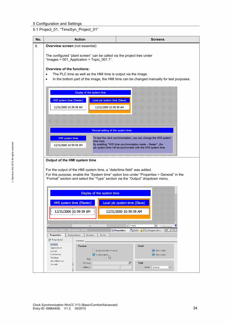
3. Overview screen (not essential) The configured “plant screen” can be called via the project tree under “Images > 001_Application > Topic_001.1”. Overview of the functions: • The PLC time as well as the HMI time is output via the image. • In the bottom part of the image, the HMI time can be changed manually for test purposes.
Clock Synchronization WinCC V13 (Basic/Comfort/Advanced) Entry-ID: 69864408, V1.3, 05/2015 30

5 Configuration and Settings 5.1 Project_01, “TimeSyn_Project_01”
S
iem
ens
AG 2
015
All r
ight
s re
serv
ed
No. Action Screens
Output of the HMI system time For the output of the HMI system time a “date/time field” was added. For this purpose, enable the “System time” option box under “Properties > General” in the “Format” section and select the “Type” section via the “Output” dropdown menu.
Output of the PLC system time For the output of the PLC system time a “date/time field” was added. Under “Properties > General” in the “Format” section, the tag configured at the output of the “RD_LOC_T” PLC system block is used (see table Link). Select the “Output” mode in the “Type” section via the dropdown menu.
Clock Synchronization WinCC V13 (Basic/Comfort/Advanced) Entry-ID: 69864408, V1.3, 05/2015 31

5 Configuration and Settings 5.1 Project_01, “TimeSyn_Project_01”
S
iem
ens
AG 2
015
All r
ight
s re
serv
ed
No. Action Screens
Specifying the HMI system time For test purposes, the HMI system time can be specified manually. This is why a “date/time field” was added. Enable the “System time” option box in the “Type” section and the “Input/output” mode via the dropdown menu under “Properties > General”.
Clock Synchronization WinCC V13 (Basic/Comfort/Advanced) Entry-ID: 69864408, V1.3, 05/2015 32

5 Configuration and Settings 5.1 Project_01, “TimeSyn_Project_01”
S
iem
ens
AG 2
015
All r
ight
s re
serv
ed
HMI_2 (Master) In this configuration the HMI operator panel is timer (master). The PLC is the time receiving component (slave).
Table 5-3
No. Action Screens
4. Connections Open the “Connections” component via the project navigation. The existing connections are displayed in the working window. Note: It is assumed that a connection to a S7-1200 or S7-1500 controller is already configured.
5. Selecting clock synchronization
Open the dropdown menu under the “HMI time synchronization mode” item and select the “Master” item there. Thus the settings for the time synchronization are completed. The HMI operator panel connected is now the timer component.
Other settings regarding the clock synchronization are not required.
Clock Synchronization WinCC V13 (Basic/Comfort/Advanced) Entry-ID: 69864408, V1.3, 05/2015 33
5 Configuration and Settings 5.1 Project_01, “TimeSyn_Project_01”
S
iem
ens
AG 2
015
All r
ight
s re
serv
ed
No. Action Screens
6. Overview screen (not essential) The configured “plant screen” can be called via the project tree under “Images > 001_Application > Topic_001.1”. Overview of the functions: • The PLC time as well as the HMI time is output via the image. • In the bottom part of the image, the HMI time can be changed manually for test purposes.
Output of the HMI system time For the output of the HMI system time, a “date/time field” was added. For this purpose, enable the “System time” option box under “Properties > General” in the “Format” section and select the “Type” section via the “Output” dropdown menu.
Clock Synchronization WinCC V13 (Basic/Comfort/Advanced) Entry-ID: 69864408, V1.3, 05/2015 34

5 Configuration and Settings 5.1 Project_01, “TimeSyn_Project_01”
S
iem
ens
AG 2
015
All r
ight
s re
serv
ed
No. Action Screens
Output of the PLC system time For the output of the PLC system time, a “date/time field” was added. Under “Properties > General” in the “Format” section the tag configured at the output of the “RD_LOC_T” PLC system block is used (Link). Select the “Output” mode in the “Type” section via the dropdown menu.
Specifying the HMI system time For test purposes, the HMI system time can be specified manually. This is why a “date/time field” was added. Enable the “System time” option box in the “Type” section and the “Input/output” mode via the dropdown menu under “Properties > General”.
Clock Synchronization WinCC V13 (Basic/Comfort/Advanced) Entry-ID: 69864408, V1.3, 05/2015 35
5 Configuration and Settings 5.2 Project_02, “TimeSyn_Project_02”
S
iem
ens
AG 2
015
All r
ight
s re
serv
ed
5.2 Project_02, “TimeSyn_Project_02”
Clock synchronization between a S7-300 and a TP1200 Comfort Panel In the example project the clock synchronization is performed via the "date/time PLC" area pointer (controller → operator panel) For the “TimeSyn_Project_02” project the following hardware is used. • CPU: S7-300 • HMI: TP1200 Comfort Panel
5.2.1 PLC program
Table 5-4
No. Action Screens
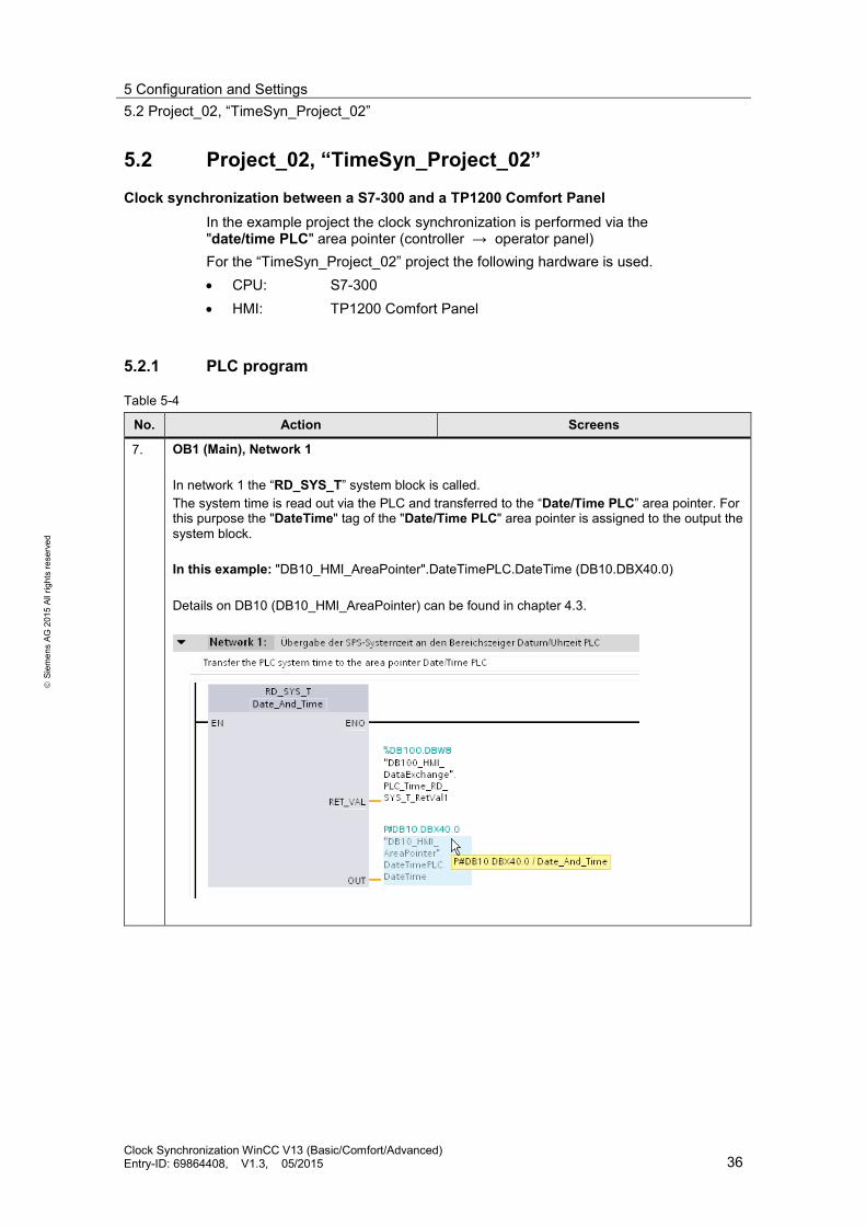
7. OB1 (Main), Network 1 In network 1 the “RD_SYS_T” system block is called. The system time is read out via the PLC and transferred to the “Date/Time PLC” area pointer. For this purpose the "DateTime" tag of the "Date/Time PLC" area pointer is assigned to the output the system block. In this example: "DB10_HMI_AreaPointer".DateTimePLC.DateTime (DB10.DBX40.0) Details on DB10 (DB10_HMI_AreaPointer) can be found in chapter 4.3.
Clock Synchronization WinCC V13 (Basic/Comfort/Advanced) Entry-ID: 69864408, V1.3, 05/2015 36

5 Configuration and Settings 5.2 Project_02, “TimeSyn_Project_02”
S
iem
ens
AG 2
015
All r
ight
s re
serv
ed
No. Action Screens
8. OB1 (Main), network 2 (not essential) In network 2 the “RD_SYS_T” system block is called. The system time of the PLC time is read out via the block. The time is output in a picture on the HMI operator panel via the tag used on the output. In this example: "DB100_HMI_DataExchange".PLC_Time_RD_SYS_T (DB100.DBX0.0) The DB100 is used for data exchange between the PLC and the HMI operator panel.
9. DB100 (DB100_HMI_DataExchange) The data exchange between the PLC and the HMI operator panel is performed via DB100.
10. Other settings regarding the clock synchronization are not required in the PLC.
Clock Synchronization WinCC V13 (Basic/Comfort/Advanced) Entry-ID: 69864408, V1.3, 05/2015 37

5 Configuration and Settings 5.2 Project_02, “TimeSyn_Project_02”
S
iem
ens
AG 2
015
All r
ight
s re
serv
ed
5.2.2 HMI configuration
HMI_1_TP1200 In this configuration the PLC is timer (master). The HMI operator panel is the time receiving component (slave).
Table 5-5
No. Action Screens
11. Connections Open the “Connections” component via the project navigation. The existing connections are displayed in the working window. Note: It is assumed that a connection to a SIMATIC S7 controller is already configured. In this example: SIMATIC S7300/400
Clock Synchronization WinCC V13 (Basic/Comfort/Advanced) Entry-ID: 69864408, V1.3, 05/2015 38

5 Configuration and Settings 5.2 Project_02, “TimeSyn_Project_02”
S
iem
ens
AG 2
015
All r
ight
s re
serv
ed
No. Action Screens
12. Selecting area pointer Enable the "Area pointer" in the "Connections" editor. The "Area pointer" tab includes two tables with area pointers. Open the “Global area pointer” table for this application. Note: You may have to open the “Global area pointer” table via the arrow button (1).
13. Configuring “Date/Time PLC” area pointer
The screen below shows the configured “Date/Time PLC” area pointer.
Description of parameters Connection: Select the PLC connection in the window. By selecting a controller the area pointer is enabled. In this example: HMI_connection Display name: Name of the area pointer. Specified by WinCC. PLC tag: Here you select the PLC tag that you have configured as data area for the area pointer. In this example: DB10_HMI_AreaPointer.DateTimePLC.DateTime Address: When you have symbolically selected the tag in the “PLC tag” box, the address of the tag is displayed in this box. Alternatively, you can specify the address of the tags manually. In this example: %DB10.DBX40.0 Length: The length of the area pointer. Specified by WinCC. Acquisition mode: In this box you specify the acquisition mode. Note that a very short acquisition time may influence the performance of the operator panel. In this example: 1 min Other settings regarding the clock synchronization are not required.
1
Clock Synchronization WinCC V13 (Basic/Comfort/Advanced) Entry-ID: 69864408, V1.3, 05/2015 39

5 Configuration and Settings 5.2 Project_02, “TimeSyn_Project_02”
S
iem
ens
AG 2
015
All r
ight
s re
serv
ed
No. Action Screens
14. Overview screen (not essential) The configured “plant screen” can be called via the project tree under “Images > 001_Application > Topic_001.1”. Overview of the functions: • The PLC time as well as the HMI time is output via the image. • In the bottom part of the image, the HMI time can be changed manually for test purposes.
Output of the HMI system time For the output of the HMI system time, a “date/time field” was added. For this purpose, enable the “System time” option box under “Properties > General” in the “Format” section and select the “Type” section via the “Output” dropdown menu.
Clock Synchronization WinCC V13 (Basic/Comfort/Advanced) Entry-ID: 69864408, V1.3, 05/2015 40
5 Configuration and Settings 5.2 Project_02, “TimeSyn_Project_02”
S
iem
ens
AG 2
015
All r
ight
s re
serv
ed
No. Action Screens
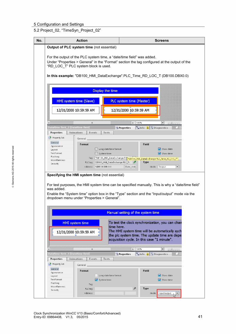
Output of PLC system time (not essential) For the output of the PLC system time, a “date/time field” was added. Under “Properties > General” in the “Format” section the tag configured at the output of the “RD_LOC_T” PLC system block is used. In this example: "DB100_HMI_DataExchange".PLC_Time_RD_LOC_T (DB100.DBX0.0)
Specifying the HMI system time (not essential) For test purposes, the HMI system time can be specified manually. This is why a “date/time field” was added. Enable the “System time” option box in the “Type” section and the “Input/output” mode via the dropdown menu under “Properties > General”.
Clock Synchronization WinCC V13 (Basic/Comfort/Advanced) Entry-ID: 69864408, V1.3, 05/2015 41

5 Configuration and Settings 5.3 Project_03, “TimeSyn_Project_03”
S
iem
ens
AG 2
015
All r
ight
s re
serv
ed
5.3 Project_03, “TimeSyn_Project_03”
Clock synchronization between a S7-300 and a TP1200 Comfort Panel In the example project the clock synchronization takes place via the "Date/Time" area pointer (operator panel → controller) and “control job” with the control job number 40. For the “TimeSyn_Project_03” project the following hardware is used. • CPU: S7-300 • HMI: TP1200 Comfort Panel
5.3.1 PLC program
Table 5-6
No. Action Screens
15. OB1 (Main), Network 1 In network 1 the “FB110”( FB110_TimeSyn_HMI_To_PLC) program block is called. The FB110 evaluates the data of the “date/time” and the “control job” area pointer and provides the system time of the PLC based on this information. The FB110 was especially created for this clock synchronization. It is not necessary to edit the program block. The block includes all necessary functions. For the implementation of the clock synchronization the FB110 only has to be configured according to the specifications. Details for the FB110 are available in chapter 4.4.
Clock Synchronization WinCC V13 (Basic/Comfort/Advanced) Entry-ID: 69864408, V1.3, 05/2015 42
5 Configuration and Settings 5.3 Project_03, “TimeSyn_Project_03”
S
iem
ens
AG 2
015
All r
ight
s re
serv
ed
No. Action Screens
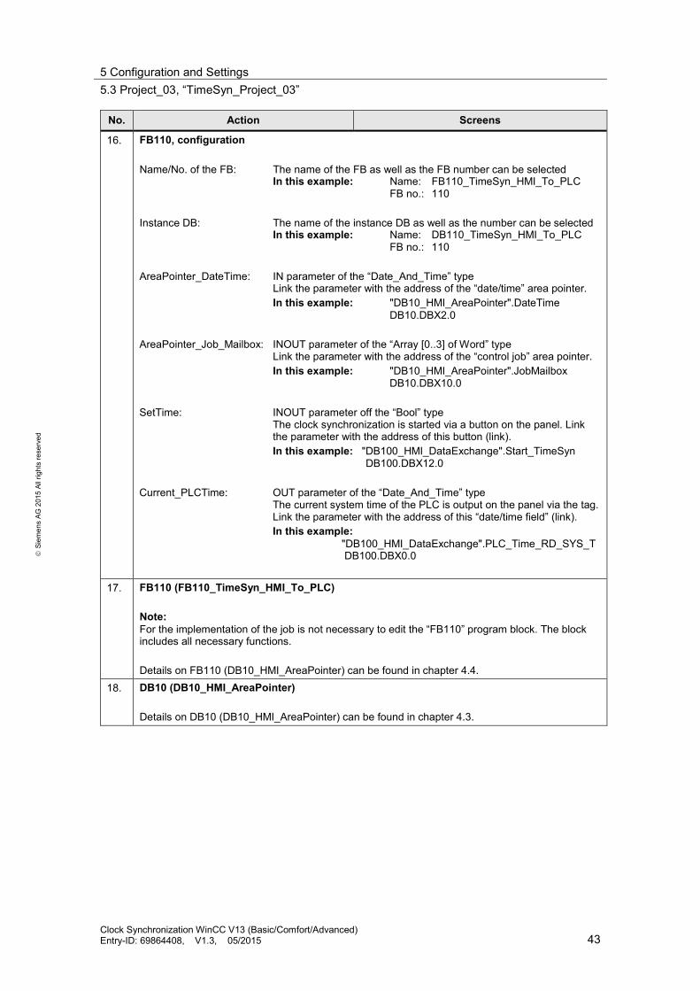
16. FB110, configuration Name/No. of the FB: The name of the FB as well as the FB number can be selected In this example: Name: FB110_TimeSyn_HMI_To_PLC FB no.: 110 Instance DB: The name of the instance DB as well as the number can be selected In this example: Name: DB110_TimeSyn_HMI_To_PLC FB no.: 110 AreaPointer_DateTime: IN parameter of the “Date_And_Time” type Link the parameter with the address of the “date/time” area pointer. In this example: "DB10_HMI_AreaPointer".DateTime DB10.DBX2.0 AreaPointer_Job_Mailbox: INOUT parameter of the “Array [0..3] of Word” type Link the parameter with the address of the “control job” area pointer. In this example: "DB10_HMI_AreaPointer".JobMailbox DB10.DBX10.0 SetTime: INOUT parameter off the “Bool” type The clock synchronization is started via a button on the panel. Link the parameter with the address of this button (link). In this example: "DB100_HMI_DataExchange".Start_TimeSyn DB100.DBX12.0 Current_PLCTime: OUT parameter of the “Date_And_Time” type The current system time of the PLC is output on the panel via the tag. Link the parameter with the address of this “date/time field” (link). In this example: "DB100_HMI_DataExchange".PLC_Time_RD_SYS_T DB100.DBX0.0
17. FB110 (FB110_TimeSyn_HMI_To_PLC) Note: For the implementation of the job is not necessary to edit the “FB110” program block. The block includes all necessary functions. Details on FB110 (DB10_HMI_AreaPointer) can be found in chapter 4.4.
18. DB10 (DB10_HMI_AreaPointer) Details on DB10 (DB10_HMI_AreaPointer) can be found in chapter 4.3.
Clock Synchronization WinCC V13 (Basic/Comfort/Advanced) Entry-ID: 69864408, V1.3, 05/2015 43

5 Configuration and Settings 5.3 Project_03, “TimeSyn_Project_03”
S
iem
ens
AG 2
015
All r
ight
s re
serv
ed
No. Action Screens
19. DB100 (DB100_HMI_DataExchange) The data exchange between the PLC and the HMI operator panel is performed via DB100.
20. DB110 (DB110_TimeSyn_HMI_To_PLC)
Instance DB for the FB110 (FB110_TimeSyn_HMI_To_PLC)
21. Other settings regarding the clock synchronization are not required in the PLC.
Clock Synchronization WinCC V13 (Basic/Comfort/Advanced) Entry-ID: 69864408, V1.3, 05/2015 44

5 Configuration and Settings 5.3 Project_03, “TimeSyn_Project_03”
S
iem
ens
AG 2
015
All r
ight
s re
serv
ed
5.3.2 HMI configuration
HMI_1_TP1200 In this configuration the operator panel is timer (master). The PLC is the time receiving component (slave).
Table 5-7
No. Action Screens
22. Connections Open the “Connections” component via the project navigation. The existing connections are displayed in the working window. Select the connection via which the operator panel is to be synchronized. In this example: HMI_connection Notes: • It is assumed that a connection to a SIMATIC S7 controller is already configured. • The area pointers used in this example can be enabled separately for each configured
connection. In this example: SIMATIC S7300/400 connection
Clock Synchronization WinCC V13 (Basic/Comfort/Advanced) Entry-ID: 69864408, V1.3, 05/2015 45

5 Configuration and Settings 5.3 Project_03, “TimeSyn_Project_03”
S
iem
ens
AG 2
015
All r
ight
s re
serv
ed
No. Action Screens
23. Selecting area pointer Enable the "Area pointer" in the "Connections" editor. The "Area pointer" tab includes two tables with area pointers. Open the “Area pointer” table for this application. The table with the “Global area pointers” is not required.
24. Configuring “Date/Time” and “control job” area pointer
Parameter description “Date/Time” Active: Enable the option box next to the “date/time” area pointer. Display name: Name of the area pointer. Specified by WinCC. PLC tag: Here you select the PLC tag that you have configured as data area for the area pointer. In this example: DB10_HMI_AreaPointer.DateTime Address: When you have symbolically selected the tag in the “PLC tag” box, the address of the tag is displayed in this box. Alternatively, you can specify the address of the tags manually. In this example: DB10.DBX2.0 Length: The length of the area pointer. Specified by WinCC. Parameter description “control job” Active: Enable the option box next to the “control job” area pointer. Display name: Name of the area pointer. Specified by WinCC. PLC tag: Here you select the PLC tag that you have configured as data area for the area pointer. In this example: DB10_HMI_AreaPointer.JobMailbox Address: When you have symbolically selected the tag in the “PLC tag” box, the address of the tag is displayed in this box. Alternatively, you can specify the address of the tags manually. In this example: DB10.DBX10.0 Length: The length of the area pointer. Specified by WinCC. Acquisition mode: In this box you specify the acquisition mode. Note that a very short acquisition time may influence the performance of the operator panel. In this example: 1 min Other settings regarding the clock synchronization are not required.
1
Clock Synchronization WinCC V13 (Basic/Comfort/Advanced) Entry-ID: 69864408, V1.3, 05/2015 46
5 Configuration and Settings 5.3 Project_03, “TimeSyn_Project_03”
S
iem
ens
AG 2
015
All r
ight
s re
serv
ed
No. Action Screens
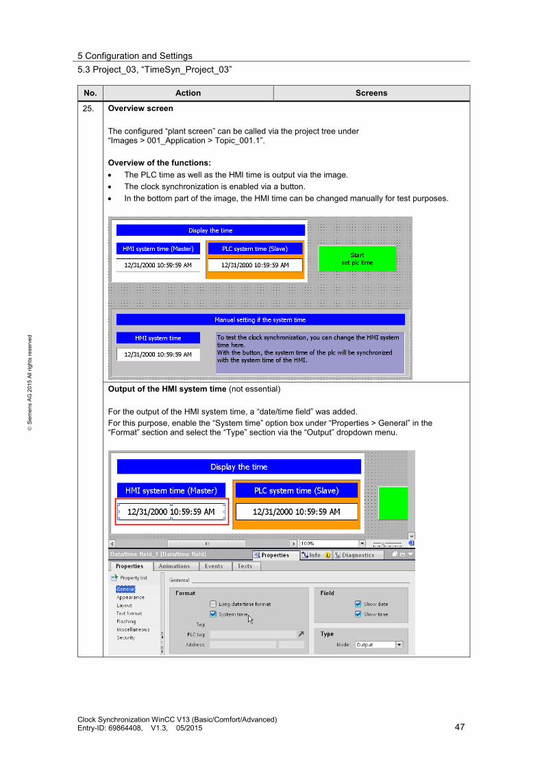
25. Overview screen The configured “plant screen” can be called via the project tree under “Images > 001_Application > Topic_001.1”. Overview of the functions: • The PLC time as well as the HMI time is output via the image. • The clock synchronization is enabled via a button. • In the bottom part of the image, the HMI time can be changed manually for test purposes.
Output of the HMI system time (not essential) For the output of the HMI system time, a “date/time field” was added. For this purpose, enable the “System time” option box under “Properties > General” in the “Format” section and select the “Type” section via the “Output” dropdown menu.
Clock Synchronization WinCC V13 (Basic/Comfort/Advanced) Entry-ID: 69864408, V1.3, 05/2015 47
5 Configuration and Settings 5.3 Project_03, “TimeSyn_Project_03”
S
iem
ens
AG 2
015
All r
ight
s re
serv
ed
No. Action Screens
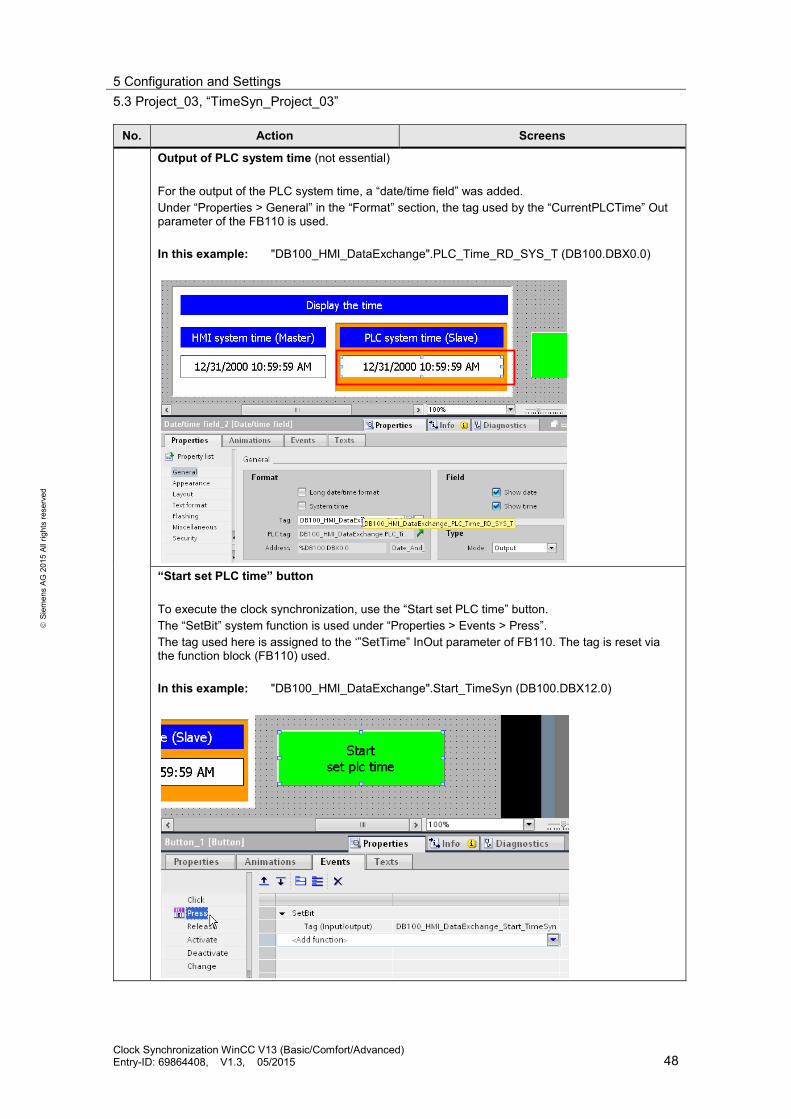
Output of PLC system time (not essential) For the output of the PLC system time, a “date/time field” was added. Under “Properties > General” in the “Format” section, the tag used by the “CurrentPLCTime” Out parameter of the FB110 is used. In this example: "DB100_HMI_DataExchange".PLC_Time_RD_SYS_T (DB100.DBX0.0)
“Start set PLC time” button To execute the clock synchronization, use the “Start set PLC time” button. The “SetBit” system function is used under “Properties > Events > Press”. The tag used here is assigned to the ‘”SetTime” InOut parameter of FB110. The tag is reset via the function block (FB110) used. In this example: "DB100_HMI_DataExchange".Start_TimeSyn (DB100.DBX12.0)
Clock Synchronization WinCC V13 (Basic/Comfort/Advanced) Entry-ID: 69864408, V1.3, 05/2015 48

5 Configuration and Settings 5.3 Project_03, “TimeSyn_Project_03”
S
iem
ens
AG 2
015
All r
ight
s re
serv
ed
No. Action Screens
Specifying the HMI system time (not essential) For test purposes, the HMI system time can be specified manually. This is why a “date/time field” was added. Enable the “System time” option box in the “Type” section and the “Input/output” mode via the dropdown menu under “Properties > General”.
Clock Synchronization WinCC V13 (Basic/Comfort/Advanced) Entry-ID: 69864408, V1.3, 05/2015 49
5 Configuration and Settings 5.4 Project_04, “TimeSyn_Project_04”
S
iem
ens
AG 2
015
All r
ight
s re
serv
ed
5.4 Project_04, “TimeSyn_Project_04”
Clock synchronization between a S7-300 and a TP1200 Comfort Panel In the example project the clock synchronization takes place via the "control job" with the • job number 14.(time) • job number 15 (date) For this clock synchronization the time and the date of the operator panel can be synchronized independently from each other with the PLC system time. For the “TimeSyn_Project_04” project the following hardware is used. • CPU: S7-300 • HMI: TP1200 Comfort Panel
5.4.1 PLC program
Table 5-8
No. Action Screens
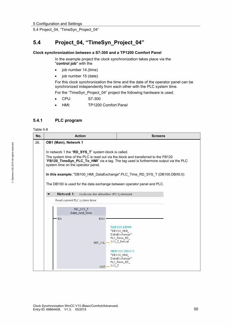
26. OB1 (Main), Network 1 In network 1 the “RD_SYS_T” system block is called. The system time of the PLC is read out via the block and transferred to the FB120 “FB120_TimeSyn_PLC_To_HMI” via a tag. The tag used is furthermore output via the PLC system time on the operator panel. In this example: "DB100_HMI_DataExchange".PLC_Time_RD_SYS_T (DB100.DBX0.0) The DB100 is used for the data exchange between operator panel and PLC.
Clock Synchronization WinCC V13 (Basic/Comfort/Advanced) Entry-ID: 69864408, V1.3, 05/2015 50

5 Configuration and Settings 5.4 Project_04, “TimeSyn_Project_04”
S
iem
ens
AG 2
015
All r
ight
s re
serv
ed
No. Action Screens
27. OB1 (Main), Network 2 In network 2 the “FB120”(FB120_TimeSyn_PLC_To_HMI) program block is called. The FB120 evaluates the data of the “control job” area pointer and provides the time and date for the operator panel based on this information. The FB120 was especially created for this clock synchronization. It is not necessary to edit the program block. The block includes all necessary functions. For the implementation of the clock synchronization the FB120 only has to be configured according to the specifications. Details for the FB120 are available in chapter 4.5.
Clock Synchronization WinCC V13 (Basic/Comfort/Advanced) Entry-ID: 69864408, V1.3, 05/2015 51

5 Configuration and Settings 5.4 Project_04, “TimeSyn_Project_04”
S
iem
ens
AG 2
015
All r
ight
s re
serv
ed
No. Action Screens
28. FB120, configuration Name/No. of the FB: The name of the FB as well as the FB number can be selected In this example: Name: FB120_TimeSyn_PLC_To_HMI FB no.: 120 Instance DB: The name of the instance DB as well as the number can be selected In this example: Name: DB120_TimeSyn_PLC_To_HMI FB no.: 120 Current_PLCTime: IN parameter of the “Date_And_Time” type The current system time of the PLC is read in via this parameter. Link the parameter with the OUT parameter of the “RD_SYS_T” (network 1) system block. In this example: "DB100_HMI_DataExchange".PLC_Time_RD_SYS_T DB100.DBX0.0 AreaPointer_Job_Mailbox: INOUT parameter of the “Array [0..3] of Word” type Link the parameter with the address of the “control job” area pointer. In this example: "DB10_HMI_AreaPointer".JobMailbox DB10.DBX10.0 SetTime: INOUT parameter off the “Bool” type The synchronization of the time on the operator panel is started via a button on the operator panel. Link the parameter with the address of the button used. In this example: "DB100_HMI_DataExchange".Start_TimeSyn DB100.DBX10.0 SetDate: INOUT parameter off the “Bool” type The synchronization of the date on the operator panel is started via a button on the operator panel. Link the parameter with the address of the button used. In this example: "DB100_HMI_DataExchange".Start_DateSyn DB100.DBX10.1
29. DB10 (DB10_HMI_AreaPointer) Details on DB10 (DB10_HMI_AreaPointer) can be found in chapter 4.3.
Clock Synchronization WinCC V13 (Basic/Comfort/Advanced) Entry-ID: 69864408, V1.3, 05/2015 52

5 Configuration and Settings 5.4 Project_04, “TimeSyn_Project_04”
S
iem
ens
AG 2
015
All r
ight
s re
serv
ed
No. Action Screens
30. DB100 (DB100_HMI_DataExchange) The data exchange between the PLC and the HMI operator panel is performed via DB100.
31. DB120 (DB110_TimeSyn_HMI_To_PLC)
Instance DB for the FB120 (FB110_TimeSyn_PLC_To_ HMI)
32. Other settings regarding the clock synchronization are not required in the PLC.
Clock Synchronization WinCC V13 (Basic/Comfort/Advanced) Entry-ID: 69864408, V1.3, 05/2015 53
5 Configuration and Settings 5.4 Project_04, “TimeSyn_Project_04”
S
iem
ens
AG 2
015
All r
ight
s re
serv
ed
5.4.2 HMI configuration
HMI_1_TP1200 In this configuration the PLC is timer (master). The HMI operator panel is the time receiving component (slave).
Table 5-9
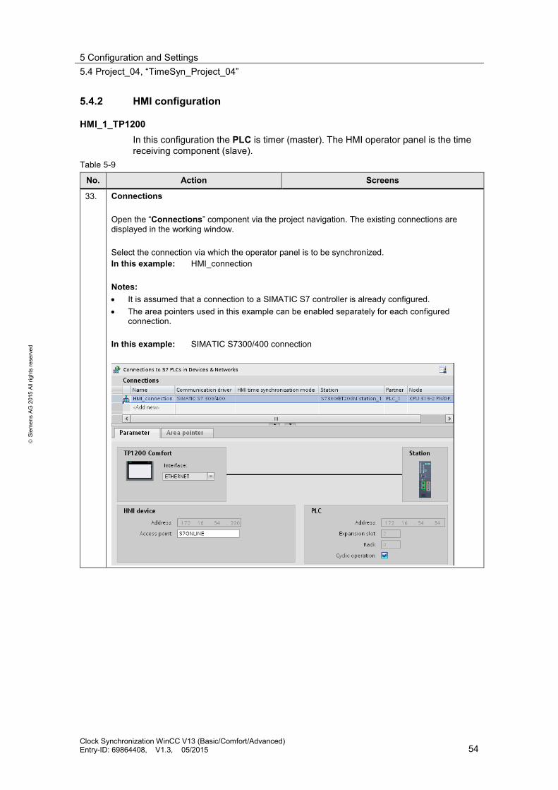
No. Action Screens
33. Connections Open the “Connections” component via the project navigation. The existing connections are displayed in the working window. Select the connection via which the operator panel is to be synchronized. In this example: HMI_connection Notes: • It is assumed that a connection to a SIMATIC S7 controller is already configured. • The area pointers used in this example can be enabled separately for each configured
connection. In this example: SIMATIC S7300/400 connection
Clock Synchronization WinCC V13 (Basic/Comfort/Advanced) Entry-ID: 69864408, V1.3, 05/2015 54

5 Configuration and Settings 5.4 Project_04, “TimeSyn_Project_04”
S
iem
ens
AG 2
015
All r
ight
s re
serv
ed
No. Action Screens
34. Selecting area pointer Enable the "Area pointer" in the "Connections" editor. The "Area pointer" tab includes two tables with area pointers. Open the “Area pointer” table for this application. The table with the “Global area pointers” (1) is not required.
35. Configure the “control job” area pointer
Parameter description “control job” Active: Enable the option box next to the “control job” area pointer. Display name: Name of the area pointer. Specified by WinCC. PLC tag: Here you select the PLC tag that you have configured as data area for the area pointer. In this example: DB10_HMI_AreaPointer.JobMailbox Address: When you have symbolically selected the tag in the “PLC tag” box, the address of the tag is displayed in this box. Alternatively, you can specify the address of the tags manually. In this example: DB10.DBX10.0 Length: The length of the area pointer. Specified by WinCC. Acquisition mode: In this box you specify the acquisition mode. Note that a very short acquisition time may influence the performance of the operator panel. In this example: 1 s Other settings regarding the clock synchronization are not required.
1
Clock Synchronization WinCC V13 (Basic/Comfort/Advanced) Entry-ID: 69864408, V1.3, 05/2015 55

5 Configuration and Settings 5.4 Project_04, “TimeSyn_Project_04”
S
iem
ens
AG 2
015
All r
ight
s re
serv
ed
No. Action Screens
36. Overview screen The configured “plant screen” can be called via the project tree under “Images > 001_Application > Topic_001.1”. Overview of the functions: • The PLC time as well as the HMI time is output via the image. • The clock synchronization is enabled via two buttons. • In the bottom part of the image, the HMI time can be changed manually for test purposes.
Output of the HMI system time (not essential) For the output of the HMI system time, a “date/time field” was added. For this purpose, enable the “System time” option box under “Properties > General” in the “Format” section and select the “Type” section via the “Output” dropdown menu.
Clock Synchronization WinCC V13 (Basic/Comfort/Advanced) Entry-ID: 69864408, V1.3, 05/2015 56
5 Configuration and Settings 5.4 Project_04, “TimeSyn_Project_04”
S
iem
ens
AG 2
015
All r
ight
s re
serv
ed
No. Action Screens
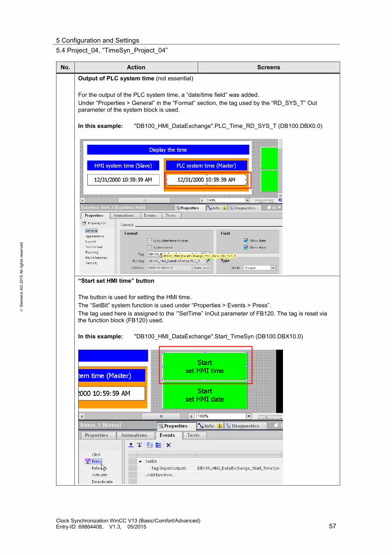
Output of PLC system time (not essential) For the output of the PLC system time, a “date/time field” was added. Under “Properties > General” in the “Format” section, the tag used by the “RD_SYS_T” Out parameter of the system block is used. In this example: "DB100_HMI_DataExchange".PLC_Time_RD_SYS_T (DB100.DBX0.0)
“Start set HMI time” button The button is used for setting the HMI time. The “SetBit” system function is used under “Properties > Events > Press”. The tag used here is assigned to the ‘”SetTime” InOut parameter of FB120. The tag is reset via the function block (FB120) used. In this example: "DB100_HMI_DataExchange".Start_TimeSyn (DB100.DBX10.0)
Clock Synchronization WinCC V13 (Basic/Comfort/Advanced) Entry-ID: 69864408, V1.3, 05/2015 57

5 Configuration and Settings 5.4 Project_04, “TimeSyn_Project_04”
S
iem
ens
AG 2
015
All r
ight
s re
serv
ed
No. Action Screens
“Start set HMI date” button The button is used for setting the HMI date. The “SetBit” system function is used under “Properties > Events > Press”. The tag used here is assigned to the “SetDate” InOut parameter of the FB120. The tag is reset via the function block (FB120) used. In this example: "DB100_HMI_DataExchange".Start_DateSyn (DB100.DBX10.1)
Specifying the HMI time (not essential) For test purposes, the HMI time can be specified manually. This is why a “date/time field” was added. Enable the “System time” option box and in the “Field” section the “Show time” option box under “Properties > General” in the “Format” section.
Clock Synchronization WinCC V13 (Basic/Comfort/Advanced) Entry-ID: 69864408, V1.3, 05/2015 58

5 Configuration and Settings 5.4 Project_04, “TimeSyn_Project_04”
S
iem
ens
AG 2
015
All r
ight
s re
serv
ed
No. Action Screens
Specifying the HMI date (not essential) For test purposes, the HMI date can be specified manually. This is why a “date/time field” was added. Enable the “System time” option box and in the “Field” section the “Show time” option box under “Properties > General” in the “Format” section.
Clock Synchronization WinCC V13 (Basic/Comfort/Advanced) Entry-ID: 69864408, V1.3, 05/2015 59
6 Operating the Application 6.1 General information
S
iem
ens
AG 2
015
All r
ight
s re
serv
ed
6 Operating the Application 6.1 General information
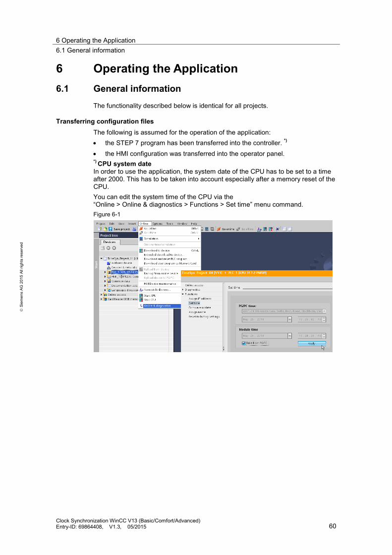
The functionality described below is identical for all projects.
Transferring configuration files The following is assumed for the operation of the application: • the STEP 7 program has been transferred into the controller. *) • the HMI configuration was transferred into the operator panel. *) CPU system date In order to use the application, the system date of the CPU has to be set to a time after 2000. This has to be taken into account especially after a memory reset of the CPU. You can edit the system time of the CPU via the “Online > Online & diagnostics > Functions > Set time” menu command. Figure 6-1
Clock Synchronization WinCC V13 (Basic/Comfort/Advanced) Entry-ID: 69864408, V1.3, 05/2015 60
6 Operating the Application 6.1 General information
S
iem
ens
AG 2
015
All r
ight
s re
serv
ed
6.1.1 Calling the “Plant images”
Start screen With the start of the HMI project on the operator panel, the following start screen is displayed. You get to the navigation overview of the created plant images for the clock synchronization via the “Application example” button. Figure 6-2
Navigation overview This screen gives you the navigation overview of the configured plant images. In this example there is only the “Overview” image. The “overview” image gives a summary of the task description. The “time synchronization” button takes you to the “plant screen” of the time synchronization. Figure 6-3
Clock Synchronization WinCC V13 (Basic/Comfort/Advanced) Entry-ID: 69864408, V1.3, 05/2015 61

6 Operating the Application 6.1 General information
S
iem
ens
AG 2
015
All r
ight
s re
serv
ed
6.1.2 Functionality of the plant screens
The screen shot below shows the user interface. Apart from the labeling, the objects shown in this screen are identical in all the example projects. Figure 6-4
Point 1: There are two output fields in the top area of the image. The system time of the HMI operator panel as well as the system time of the PLC, are output via the output fields. The two output fields are not essential for the implementation of the clock synchronization. Point 2: The “Input/output field” in the bottom part of the screen is used to test the functionality of the clock synchronization. The system time of the HMI operator panel can be specified manually via the “I/O field”. If the system time of the “slave system” differs from the “master system”, the time of the “slave system” is automatically synchronized with that of the “master system” (depending of the clock synchronization used). The “input/output field” is not essential for the implementation of the clock synchronization.
1
2
Clock Synchronization WinCC V13 (Basic/Comfort/Advanced) Entry-ID: 69864408, V1.3, 05/2015 62

6 Operating the Application 6.2 Project_01, TimeSyn_Project_01
S
iem
ens
AG 2
015
All r
ight
s re
serv
ed
6.2 Project_01, TimeSyn_Project_01
Clock synchronization between a S7-1200 and a TP1200 Comfort Panel. The clock synchronization is performed via the HMI system function “HMI time synchronization mode” (master/slave).
– PLC (Master) → HMI operator panel (Slave). – HMI operator panel (Master) → PLC (Slave).
HMI_01_TP1200_Slave PLC (Master) → HMI operator panel (Slave)
Table 6-1
No. Action Screens
37. Calling clock synchronization Call the time synchronization via the „Application example > Overview > Time synchronization” button.
38. Specifying HMI time Change the HMI system time via the I/O field and complete the entry with the “Enter” button (1). In this example: The HMI time (hour) was changed to 9 pm. The HMI system time is adjusted to the PLC system time within a minute.
1
Clock Synchronization WinCC V13 (Basic/Comfort/Advanced) Entry-ID: 69864408, V1.3, 05/2015 63

6 Operating the Application 6.2 Project_01, TimeSyn_Project_01
S
iem
ens
AG 2
015
All r
ight
s re
serv
ed
HMI_02_TP1200_Master HMI operator panel (Master) → PLC (Slave)
Table 6-2
No. Action Screens
39. Calling clock synchronization Call the time synchronization via the “Application example > Overview > Time synchronization” button.
40. Specifying HMI time Change the HMI system time via the I/O field and complete the entry with the “Enter” button (1). In this example: The HMI time (hour) was changed to 9 pm. The PLC system time is adjusted to the HMI system time within a minute.
1
Clock Synchronization WinCC V13 (Basic/Comfort/Advanced) Entry-ID: 69864408, V1.3, 05/2015 64

6 Operating the Application 6.3 Project_02, TimeSyn_Project_02
S
iem
ens
AG 2
015
All r
ight
s re
serv
ed
6.3 Project_02, TimeSyn_Project_02
Clock synchronization between a S7-300 and a TP1200 Comfort Panel. The clock synchronization is performed via the “Date/Time PLC” area pointer
– PLC (Master) → HMI operator panel (Slave).
HMI_01_TP1200 PLC (Master) → HMI operator panel (Slave)
Table 6-3
No. Action Screens
41. Calling clock synchronization Call the time synchronization via the “Application example > Overview > Time synchronization” button.
42. Specifying HMI time Change the HMI system time via the I/O field and complete the entry with the “Enter” button (1). In this example: The HMI time (hour) was changed to 9 am. The HMI system time is adjusted to the PLC system time within a minute.
1
Clock Synchronization WinCC V13 (Basic/Comfort/Advanced) Entry-ID: 69864408, V1.3, 05/2015 65

6 Operating the Application 6.4 Project_03, TimeSyn_Project_03
S
iem
ens
AG 2
015
All r
ight
s re
serv
ed
6.4 Project_03, TimeSyn_Project_03
Clock synchronization between a S7-300 and a TP1200 Comfort Panel. The clock synchronization is performed via the "date/clock" and "control job" area pointers with job number 40.
– Operator panel (Master) → controller (Slave).
HMI_01_TP1200 HMI operator panel (Master) → PLC (Slave)
Table 6-4
No. Action Screens
43. Calling clock synchronization Call the time synchronization via the “Application example > Overview > Time synchronization” button.
44. Specifying HMI time • Change the HMI system time via the I/O field and complete the entry with the
“Enter” button (1). • Click the “Start set plc time” button (2). In this example: The HMI time (hour) was changed to 9 am. By clicking the button the PLC system time is adjusted to the HMI system time.
1
2
Clock Synchronization WinCC V13 (Basic/Comfort/Advanced) Entry-ID: 69864408, V1.3, 05/2015 66

6 Operating the Application 6.5 Project_04, TimeSyn_Project_04
S
iem
ens
AG 2
015
All r
ight
s re
serv
ed
6.5 Project_04, TimeSyn_Project_04
Clock synchronization between a S7-300 and a TP1200 Comfort Panel. The clock synchronization is performed via the "control job" area pointer with the control job numbers 14 (time) and 15 (date).
– Controller (Master) → operator panel (Slave). For this clock synchronization, the time and the date of the operator panel can be synchronized independently from each other with the PLC system time/date.
HMI_01_TP1200 PLC (Master) → HMI operator panel (Slave)
Table 6-5
No. Action Screens
45. Calling clock synchronization Call the time synchronization via the „Application example > Overview > Time synchronization” button.
46. Specifying HMI date (alternatively, the time) • Change the HMI system date via the I/O field and complete the entry with the
“Enter” button (1). • Click the “Start set HMI date” button (3). In this example: The HMI date (month) was changed to “4”. By clicking the button (3) the HMI system date is adjusted to the PLC system date.
1
2
3
Clock Synchronization WinCC V13 (Basic/Comfort/Advanced) Entry-ID: 69864408, V1.3, 05/2015 67

7 Notes and Tips 7.1 Replacing PLC
S
iem
ens
AG 2
015
All r
ight
s re
serv
ed
7 Notes and Tips The hints and tips below are intended to provide an aid if you would like to adjust the included configurations to your project environment.
7.1 Replacing PLC
Instead of the SIMATIC controller used, a different SIMATIC controller from the WinCC TIA Portal hardware catalog can also be inserted. When replacing the SIMATIC controller, the following points should be noted or checked afterwards. • The clock synchronization via the “HMI time synchronization mode” only
supports SIMATIC S7-1200 and S7-1500 controllers. • If you are using the function blocks from the projects “TimeSyn_Project_03”
(FB110) or “TimeSyn_Project_04” (FB120), the SIMATIC controller used has to support the “STL” programming language. The FBs were created in the STL programming language.
• If, for example, the connection paths (Ethernet/PROFIBUS) have changed, check the following in the HMI configuration… – the configured HMI connection – the connections used in the global area pointers – the addresses of the area pointer used
7.2 Changing HMI operator panel
Instead of the TP1200 Comfort Panel used, you can also use a different operator panel from the WinCC TIA Portal hardware catalog. When replacing the HMI operator panel, the following points should be noted or checked afterwards. • Area pointer used
Before changing the operator panel, you have to make sure that the new operator panel supports the area pointer used. Information regarding this matter can be found in the system manual of WinCC (TIA Portal).
• Create new connection (PROFINET → PROFIBUS). If you create a new connection instead of the existing connection, you have to recreate the area pointer.
Clock Synchronization WinCC V13 (Basic/Comfort/Advanced) Entry-ID: 69864408, V1.3, 05/2015 68

8 Further notes, tips and tricks, etc. (optional)
S
iem
ens
AG 2
015
All r
ight
s re
serv
ed
8 Further notes, tips and tricks, etc. (optional)
Note What might additionally be of interest concerning the subject but not necessary for the direct understanding of the example.
Clock Synchronization WinCC V13 (Basic/Comfort/Advanced) Entry-ID: 69864408, V1.3, 05/2015 69

9 Related Literature
S
iem
ens
AG 2
015
All r
ight
s re
serv
ed
9 Related Literature 9.1 Bibliography
This list is not complete and only represents a selection of relevant literature. Table 9-1
Topic Title
/1/ STEP7 SIMATIC S7-300/400
Automating with STEP7 in STL and SCL Author: Hans Berger Publicis Publishing ISBN: 978-3895784125
/2/ STEP7 SIMATIC S7-300/400
Automating with STEP 7 in LAD and FBD Author: Hans Berger Publicis Publishing ISBN: 978-3895784101
/3/ STEP7 SIMATIC S7-300
Automating with SIMATIC S7-300 inside TIA Portal Author: Hans Berger Publicis Publishing ISBN: 978-3895783821
/4/ STEP7 SIMATIC S7-400
Automating with SIMATIC S7-300 inside TIA Portal Author: Hans Berger Publicis Publishing ISBN: 978-3895783821
/5/ STEP7 SIMATIC S7-1200
Automating with SIMATIC S7-1200 Author: Hans Berger Publicis Publishing ISBN: 978-3895783562
9.2 Internet links The following list is not complete and only represents a selection of relevant information. Table 9-2
Topic Title
\1\ Link to this document
https://support.industry.siemens.com/cs/ww/en/view/69864408
\2\ Siemens Industry Online Support
https://support.industry.siemens.com
\3\ WinCC Advanced V13.0 System Manual
https://support.industry.siemens.com/cs/ww/en/view/91479053
\4\ FAQ How do you parameterize a structured data type in the IN_OUT area of an FB and a function call with an ARRAY variable? https://support.industry.siemens.com/cs/ww/en/view/19106712
Clock Synchronization WinCC V13 (Basic/Comfort/Advanced) Entry-ID: 69864408, V1.3, 05/2015 70

10 History
S
iem
ens
AG 2
015
All r
ight
s re
serv
ed
10 History Table 10-1
Version Date Modifications
V1.0 08/2013 First version V1.1 09/2013 Chapter 2.1, note added V1.2 11/2013 Control job 13/14 => Control job 14/15 V1.3 04/2015 Initialize FB210
Clock Synchronization WinCC V13 (Basic/Comfort/Advanced) Entry-ID: 69864408, V1.3, 05/2015 71