applicability evaluation of steel plate reinforced
TRANSCRIPT
Transactions, SMiRT-23
Manchester, United Kingdom - August 10-14, 2015
Division V, Paper ID 258
APPLICABILITY EVALUATION OF STEEL PLATE REINFORCED
CONCRETE STRUCTURE TO PRIMARY CONTAINMENT VESSEL OF
BWRS
(3) COMPRESSIVE LOADING TEST OF STEEL PLATE
REINFORCED CONCRETE STRUCTURE UNDER HIGH
TEMPERATURE CONDITIONS
Shintaro Narita1, Masaaki Osaka
2, Tomohisa Kurita
3, Tomohiro Kobayashi
4,
Norichika Kakae5, Yoshihisa Kobayashi
6
1 Staff Engineer, Hitachi-GE Nuclear Energy, Ltd. Japan 2 Manager, Hitachi-GE Nuclear Energy, Ltd. Japan 3 Senior Manager, Toshiba Corporation, Japan 4 Senior Engineer, Kajima Corporation, Japan 5 Senior Research Engineer, Kajima Corporation, Japan 6 General Manager, Tokyo Electric Power Company, Inc. Japan
ABSTRACT
Since the steel plate of steel plate reinforced concrete containment vessel (SCCV) is directly exposed to
high temperature under accident conditions, thermal thrust that may cause buckling of steel plate is
generated. In this study, compressive loading tests of steel plate reinforced concrete (SC) specimens
under high temperature up to 200°C were conducted in order to obtain the compressive property of SC
structure. The buckling of steel plate is not observed under the vertically restrained condition until 200°C.
After the continuing compressive loading that causes steel plate buckling, specimens reach maximum
compressive strength. Simulation analysis using elasto-plastic finite element analysis code was
conducted, and it was confirmed that analyses could simulate the buckling behavior of steel plate. The
relationship between ratio of stud pitch to steel plate thickness and the steel plate strain at the time of
buckling under high temperature is examined.
INTRODUCTION
Steel plate reinforced concrete containment vessel (SCCV) is directly exposed to high temperature under
accident conditions. To evaluate the applicability of SC structure to Primary Containment Vessel (PCV),
it is required to confirm the compression resistance of SC structure and the behavior of the buckling of
steel plate in high temperature environment. The test purpose is to collect data for the evaluation of load-
displacement relationship, and for the understanding the phenomenon of yield and buckling of steel plate
under high temperature environment.
23rd Conference on Structural Mechanics in Reactor Technology
Manchester, United Kingdom - August 10-14, 2015
Division V
EXPERIMENTAL DETAILS
Specification of the test specimen
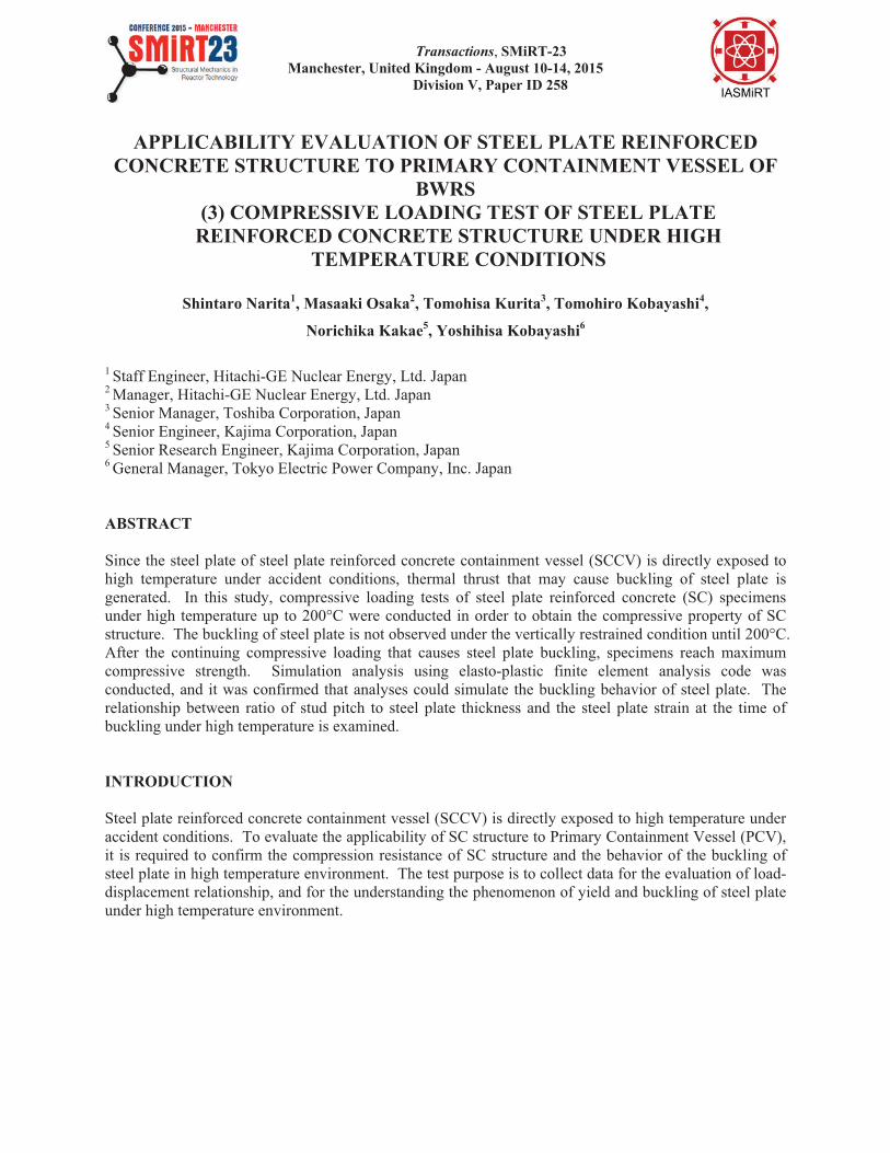
The test specimen is a partial model of the internal surface of SCCV wall (the side exposed to high
temperature). It is modelled in 1/2 scale of the expected actual structure. Figure 1 shows the
configuration of the test specimen. Figure 2 shows the shape of the test specimen. As shown in Figure 1
the test specimen has test portions at both sides arranged symmetrically, and fixed upper and lower ends
with Reinforced Concrete (RC) stubs for the force application. The test specimen is heated from both
sides.
The steel plate is made of SPV490 (JIS G 3115: Yield stress:490MPa, Ultimate strength:610MPa), which
is a proven primary containment material in Japan. The specified design compressive strength of concrete
is 33N/mm2, which is the same as RCCV (Reinforced Concrete Containment Vessel), which has
operational experiences in Japan. The material age of concrete for test specimen is more than 91days.
Figure 1. Configuration of the test specimen. Figure 2. Shape of the test specimen.
Test parameters
The test parameters are temperature, heating duration, stud pitch, restraint conditions when heating, and
compression loading method. Table 1 shows the test matrix set, considering the following parameters (1)
through (4).
(1) Temperature conditions
The temperature conditions in this test are set based on the assumed temperature conditions under design
basis accident (DBA) and severe accident (SA) of SCCV. Assuming short-term has passed after accident,
the test case of 175 is set. In this condition, temperature difference between surface of steel plate and
concrete is large. Assuming long-term has passed after accident, the test cases of 145 and 200 are set.
In these conditions, the steel plate and concrete are both under high-temperature conditions. In addition,
to evaluate the effect of heating history, one heat removal case is also set. The test specimen of heat
removal case is cooled after 145 heating.
Partial Scale model
Specimen
100mm 200mm
Fc331/2(Scale down)SymmetricalArrangement
Plate
(6mm thick)
SCCV
Fc33
Heat
2000mm
200mm
Inside Plate
12mm thick
Surface Part
200mm thick
Heat Heat Heat
:Test part
RC stub
RC stub
Front side Back side
Tie bar!5@63
(
Front View Cross Section(B-B’)
D19@125
PL6.0PL6.0
D19@125
Tie bar!5@63
B
B’
PL20 PL6.0
300550
1150
300 200 200 200
600
Stud!9@120
(L=72)
@120 3
=360
@120
5=
600

23rd Conference on Structural Mechanics in Reactor Technology
Manchester, United Kingdom - August 10-14, 2015
Division V
(2) Stud pitch
The buckling of the steel plate constituting the SC structure depends on the ratio of the stud pitch (B) and
the steel plate thickness (t). In this test, B/t=20 is set as the standard. In previous studies, elastic buckling
does not occur when steel plate’s B/t is equal to 20 under high temperature. However, to obtain the data
for the rationalization study of the stud number, B/t=30 case is also set.
(3) Restraint conditions when heating
In this test, after the test specimen is heated to a predetermined temperature, the compressive force is
planned to be loaded. Two cases of restraint conditions when heating are considered: a) case of
restraining the thermal displacement of the test specimen while heating (“Fixed” condition) and b) case of
not restraining the thermal displacement of the test specimen while heating (“Free” condition). Since the
main purpose of this study is to understand the behavior of steel plate with thermal strain, and
compressive buckling, the “Fixed” cases are set as the standard. To evaluate the effect of restraint
conditions, one “Free” condition case is also conducted.
(4) Compression loading method
To confirm the condition of the steel plate at each load level set in steps and the tendency of stiffness
when unloading, cyclic compressive load is applied to the test specimen. To evaluate the effect of
loading methods, one monotonic loading case is conducted.
Table 1: Test matrix.
No.
Temperature conditions B/t Restraint
conditions Loading method
Room
temp. 175
Short term
145
Long term
200
Long term20 30 Fixed Free Cyclic Monotonic
1 X - - - X - - - X -
2 - - X - X - X - X -
3 - X - - X - X - X -
4 - X - - X - - X - X
5 - X - - - X X - X -
6 - - - X X - X - X -
7 - - X *1 - X - X - X -
*1: Heat removal case.
Test Method
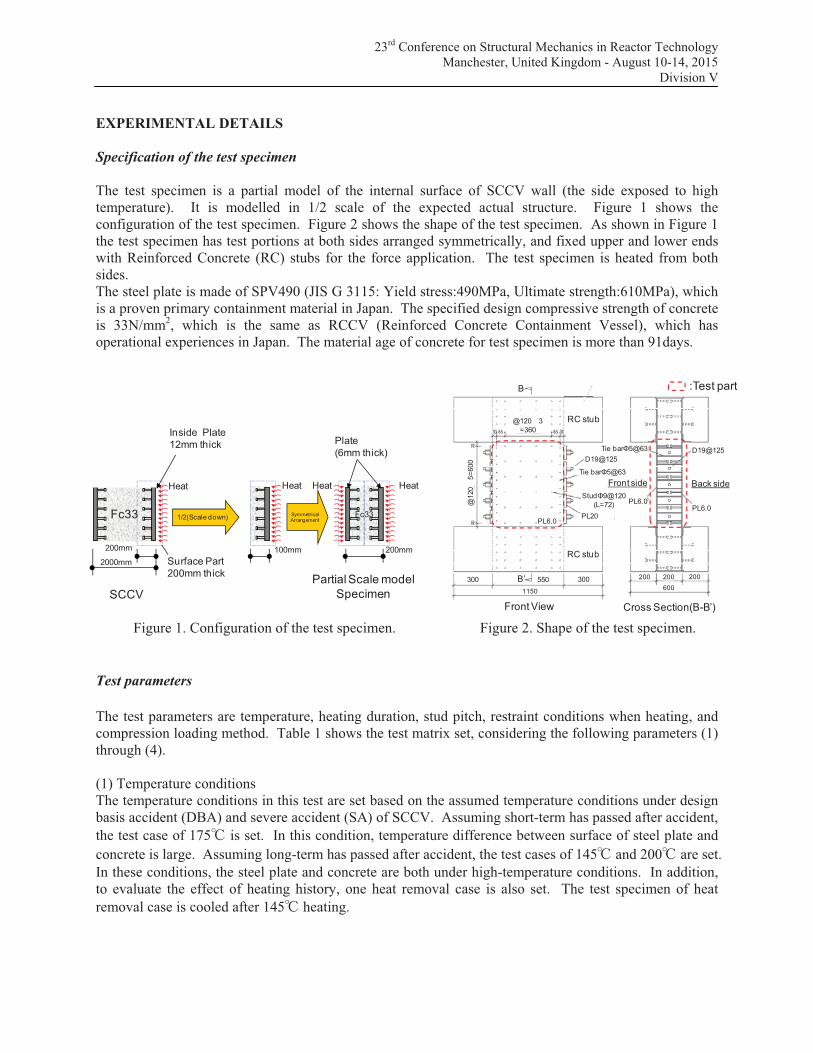
In this test, after the test specimen is heated to a predetermined temperature, the compressive axial force
is loaded. (During the loading of compressive force, the temperature of test specimen is maintained.) By
using an electric heater, the test specimens are heated until the temperature distribution in the cross
section becomes the same as the temperature distribution of the assumed SCCV wall. After above initial
heating, the compressive load in the axial direction is applied on test specimen using two hydraulic jacks
capacity of 10,000kN, through the RC stub which is provided at the upper and lower ends of the specimen.
The test specimen is shown in Figure 3. The heating and compressive loading apparatus is shown in
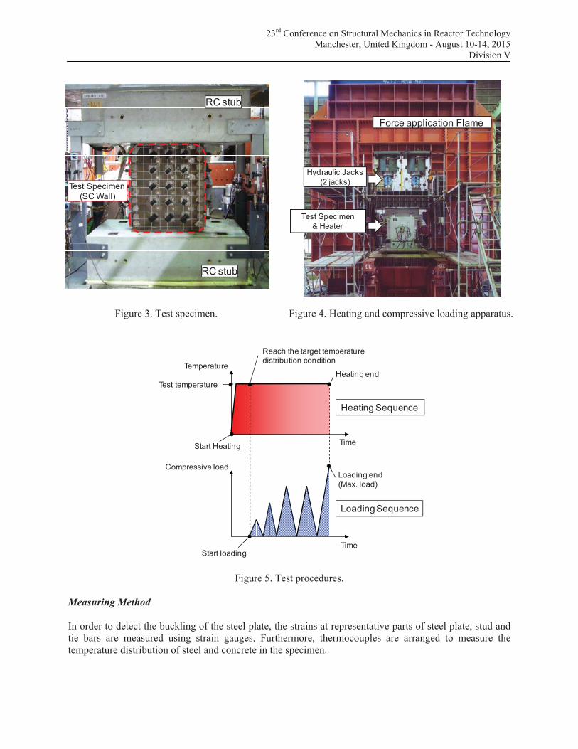
Figure 4. In the cyclic load test, the loading sequence as shown in Figure 5 is applied to the test specimen.
23rd Conference on Structural Mechanics in Reactor Technology
Manchester, United Kingdom - August 10-14, 2015
Division V
Figure 3. Test specimen. Figure 4. Heating and compressive loading apparatus.
Loading end
(Max. load)
Start loadingTime
Compressive load
Heating end
Reach the target temperature
distribution condition
TimeStart Heating
Temperature
Heating Sequence
Loading Sequence
Test temperature
Figure 5. Test procedures.
Measuring Method
In order to detect the buckling of the steel plate, the strains at representative parts of steel plate, stud and
tie bars are measured using strain gauges. Furthermore, thermocouples are arranged to measure the
temperature distribution of steel and concrete in the specimen.
RC stub
RC stub
Test Specimen
(SC Wall)
Test Specimen
& Heater
Hydraulic Jacks
(2 jacks)
Force application Flame
23rd Conference on Structural Mechanics in Reactor Technology
Manchester, United Kingdom - August 10-14, 2015
Division V
RESULTS AND DISCUSSIONS
Test Results
Test results are shown in Table 2.
Table 2: Test results.
No. Test
condition
Compressive
strength of
concrete
[N/mm2]
Compressive
load at the
start of the
out-of-plane
deformation
[kN]
Compressive
strain at the
start of the
out-of-plane
deformation*1
[ ]
Maximum
compressive
load
[kN]
Compressive
strain at the
maximum
compressive
load*1
[ ]
1 Room temp. 49.2 8766 3841 9063 4306
2 145 47.6 6798 3194 7575 3711
3 175 51.1 6182 3560 6511 3701
4 175
[Free / Monotonic] 46.3 6417 3288 6789 3594
5 175
[B/t=30] 50.6 3932 1963 5109 2975
6 200 52.1 4073 2505 5604 8699
7 145
[Heat removal] 46.6 8272 3726 8443 3886
*1: Value of strain converted from vertical displacement of the steel plate.
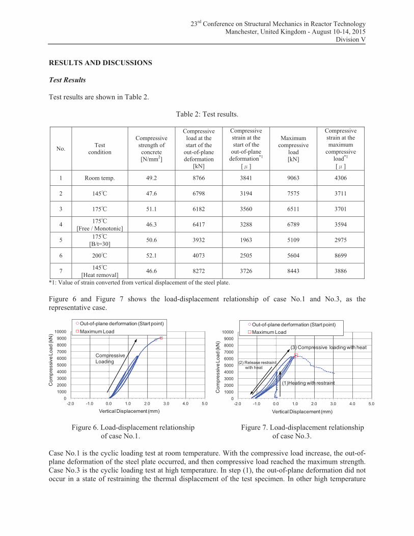
Figure 6 and Figure 7 shows the load-displacement relationship of case No.1 and No.3, as the
representative case.
Figure 6. Load-displacement relationship Figure 7. Load-displacement relationship
of case No.1. of case No.3.
Case No.1 is the cyclic loading test at room temperature. With the compressive load increase, the out-of-
plane deformation of the steel plate occurred, and then compressive load reached the maximum strength.
Case No.3 is the cyclic loading test at high temperature. In step (1), the out-of-plane deformation did not
occur in a state of restraining the thermal displacement of the test specimen. In other high temperature
0
1000
2000
3000
4000
5000
6000
7000
8000
9000
10000
-2.0 -1.0 0.0 1.0 2.0 3.0 4.0 5.0
Co
mp
ressiv
e L
oa
d (kN
)
Vertical Displacement (mm)
Out-of-plane derformation (Start point)
Maximum Load
Compressive
Loading
0
1000
2000
3000
4000
5000
6000
7000
8000
9000
10000
-2.0 -1.0 0.0 1.0 2.0 3.0 4.0 5.0
Co
mp
ressiv
e L
oa
d (kN
)
Vertical Displacement (mm)
Out-of-plane derformation (Start point)
Maximum Load
(3) Compressive loading with heat
(1)Heating with restraint
(2) Release restraint
with heat

23rd Conference on Structural Mechanics in Reactor Technology
Manchester, United Kingdom - August 10-14, 2015
Division V
conditions, the result was the same. Then in step (2), the restraint of the specimen was released while
maintaining the heating, and in step (3), with the compressive load increasing, the out-of-plane
deformation of the steel plate occurred, and then compressive load reached the maximum strength.
Figure 8 and Figure 9 shows the load-displacement relationship showing load sharing of steel plate and
concrete for the cases described above.
0
1000
2000
3000
4000
5000
6000
7000
8000
9000
10000
-2.0 -1.0 0.0 1.0 2.0 3.0 4.0 5.0
Co
mp
ressiv
e lo
ad
(kN
)
Vertical displacement (mm)
SC structure (Total)
Concrete
Steel plateMax. compressive load
(Concrete)
Buckling
Simple cumulative load
(Concrete & Steel)
Max. strength of SC specimen
Max. compressive load
(Steel plate)
Figure 8. Load-displacement relationship of case No.1 (showing load sharing).
0
1000
2000
3000
4000
5000
6000
7000
8000
9000
10000
-2.0 -1.0 0.0 1.0 2.0 3.0 4.0 5.0
Co
mp
ressiv
e lo
ad
(kN
)
Vertical displacement (mm)
SC structure (Total)
Concrete
Steel plate Max. compressive load
(Concrete)
Buckling
Simple cumulative load
(Concrete & Steel)
Max. compressive load
(Steel plate)
Difference in thermal expansion
between the steel and concrete
Max. strength of SC specimen
Figure 9. Load-displacement relationship of case No.3 (showing load sharing).
Figure 8 shows that at room temperature, the maximum strength of SC specimens measured in the test is
approximately equal to the simple cumulative compressive load of steel and concrete. On the other hand,
Figure 9 shows that at high temperature, the maximum strength of SC specimens measured in the test is
lower than the simple cumulative compressive load of steel and concrete. At high temperature condition,
since difference in thermal expansion between the steel plate and the concrete occurs, the load sharing

23rd Conference on Structural Mechanics in Reactor Technology
Manchester, United Kingdom - August 10-14, 2015
Division V
ratio of concrete when the out-of-plane deformation of the steel plate occurs is small. As a result, it is
considered that the concept of the cumulative load is not satisfied.
Parametric study
Figure 10 shows the comparison of compressive load-strain relationship in the cases of the temperature
conditions in the test of the B/t=20. The starting point of the out-of-plane deformation of steel plate is
distributed to between 2500! to 4000!, which is the same level as the yield strain of the steel plate (about
3400!). In order to confirm the effects of stud pitch and loading method, a comparison of compressive
load-strain relationship in case 3, 4, 5 is shown in Figure 11. With the expansion of the stud pitch, the
out-of-plane deformation of the steel plate occurs at smaller compressive strain. In addition, since the
compressive stiffness and compressive strength of cyclic loading and monotonic loading are
approximately equivalent, the effects of loading conditions are small. In order to confirm the effects of
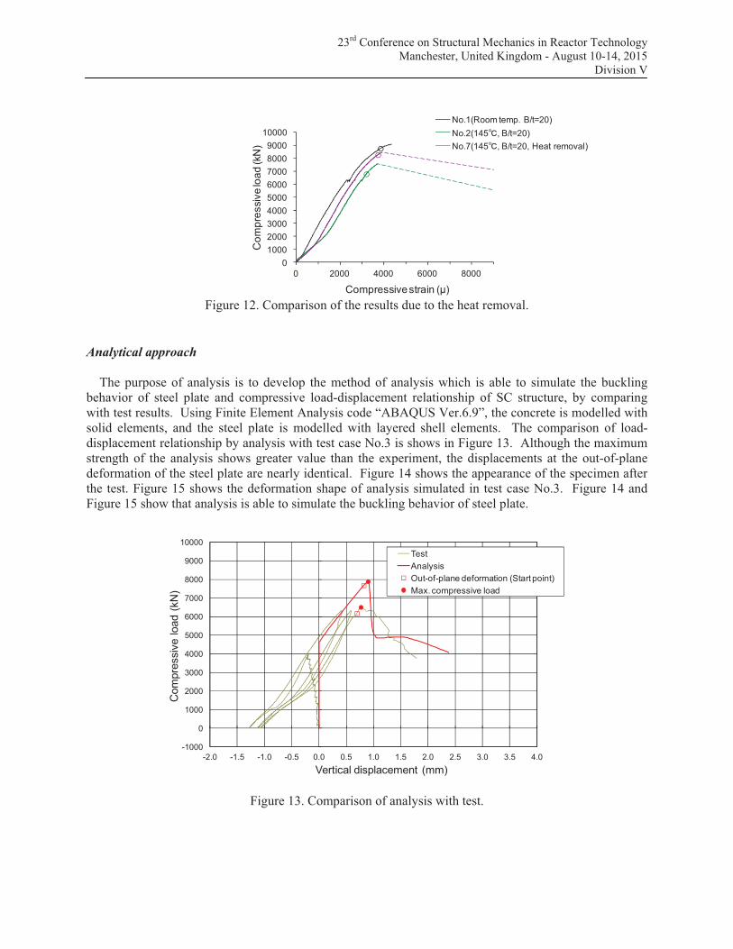
heat removal, a comparison of compressive load-strain relationship in case 1, 2, 7 is shown in Figure 12.
Even when applying compressive load after heat removal, the starting point of the out-of-plane
deformation of the steel plate is equivalent to the room temperature case. In addition, the compressive
strength and the deformation characteristics after heat removal show an intermediate property of the test
results at room temperature and high temperature.
0
1000
2000
3000
4000
5000
6000
7000
8000
9000
10000
0 2000 4000 6000 8000
Co
mp
ressiv
e lo
ad
(kN
)
Compressive strain (")
No.1(Room temp. B/t=20)
No.2(145 , B/t=20)
No.3(175 , B/t=20)
No.4(175 , B/t=20, Monotonic Loading)
No.6(200 , B/t=20)
Figure 10. Comparison of the results due to the temperature conditions.
0
1000
2000
3000
4000
5000
6000
7000
8000
9000
10000
0 2000 4000 6000 8000
Co
mp
ressiv
e lo
ad
(kN
)
Compressive strain (")
No.3(175 , B/t=20)
No.4(175 , B/t=20, Monotonic Loading)
No.5(175 , B/t=30)
Figure 11. Comparison of the results due to the stud pitch and loading method.
23rd Conference on Structural Mechanics in Reactor Technology
Manchester, United Kingdom - August 10-14, 2015
Division V
0
1000
2000
3000
4000
5000
6000
7000
8000
9000
10000
0 2000 4000 6000 8000
Co
mp
ressiv
e lo
ad
(kN
)
Compressive strain (")
No.1(Room temp. B/t=20)
No.2(145 , B/t=20)
No.7(145 , B/t=20, Heat removal)
Figure 12. Comparison of the results due to the heat removal.
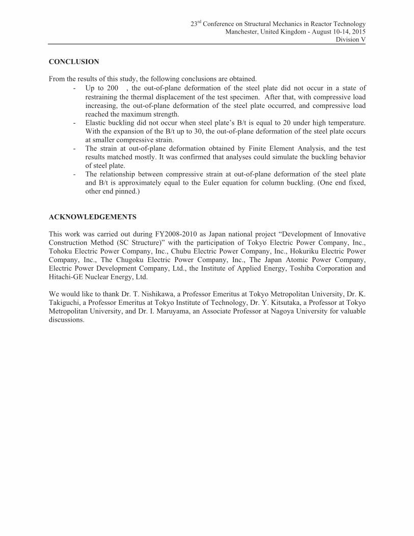
Analytical approach
The purpose of analysis is to develop the method of analysis which is able to simulate the buckling
behavior of steel plate and compressive load-displacement relationship of SC structure, by comparing
with test results. Using Finite Element Analysis code “ABAQUS Ver.6.9”, the concrete is modelled with
solid elements, and the steel plate is modelled with layered shell elements. The comparison of load-
displacement relationship by analysis with test case No.3 is shows in Figure 13. Although the maximum
strength of the analysis shows greater value than the experiment, the displacements at the out-of-plane
deformation of the steel plate are nearly identical. Figure 14 shows the appearance of the specimen after
the test. Figure 15 shows the deformation shape of analysis simulated in test case No.3. Figure 14 and
Figure 15 show that analysis is able to simulate the buckling behavior of steel plate.
-1000
0
1000
2000
3000
4000
5000
6000
7000
8000
9000
10000
-2.0 -1.5 -1.0 -0.5 0.0 0.5 1.0 1.5 2.0 2.5 3.0 3.5 4.0
Com
pre
ssiv
e load (
kN
)
Vertical displacement (mm)
Test
Analysis
Out-of-plane deformation (Start point)
Max. compressive load
Figure 13. Comparison of analysis with test.

23rd Conference on Structural Mechanics in Reactor Technology
Manchester, United Kingdom - August 10-14, 2015
Division V
Compressive load
Out-of -plane
deformation
Compressive load
Out-of-plane
deformation
Figure 14. Appearance of the specimen (test No.3). Figure 15. Deformation shape of analytical model
(Deformation magnification 5 times).
Evaluation of buckling strain
Figure 16 shows the relationship between “dimensionless strain” normalized by y at out-of-plane
deformation and “dimensionless ratio of stud pitch to steel plate thickness” normalized by ( y/E).
These plots represent the results of test. The relationship between compressive strain at out-of-plane
deformation of the steel plate and B/t is approximately equal to the Euler equation for column buckling.
(One end fixed, other end pinned.)
0.00
0.20
0.40
0.60
0.80
1.00
1.20
1.40
1.60
1.80
2.00
Dim
en
sio
nle
ss s
tra
in: #
cr/#y
Dimensionless ratio of stud pitch to steel plate thickness: B/t $%y/E
Euler equation
Room temperature
145
175
200
145 -Heat removal
Figure 16. Relationship between dimensionless strain at out-of-plane deformation
and dimensionless ratio of stud pitch to steel plate thickness.
23rd Conference on Structural Mechanics in Reactor Technology
Manchester, United Kingdom - August 10-14, 2015
Division V
CONCLUSION
From the results of this study, the following conclusions are obtained.
- Up to 200 , the out-of-plane deformation of the steel plate did not occur in a state of
restraining the thermal displacement of the test specimen. After that, with compressive load
increasing, the out-of-plane deformation of the steel plate occurred, and compressive load
reached the maximum strength.
- Elastic buckling did not occur when steel plate’s B/t is equal to 20 under high temperature.
With the expansion of the B/t up to 30, the out-of-plane deformation of the steel plate occurs
at smaller compressive strain.
- The strain at out-of-plane deformation obtained by Finite Element Analysis, and the test
results matched mostly. It was confirmed that analyses could simulate the buckling behavior
of steel plate.
- The relationship between compressive strain at out-of-plane deformation of the steel plate
and B/t is approximately equal to the Euler equation for column buckling. (One end fixed,
other end pinned.)
ACKNOWLEDGEMENTS
This work was carried out during FY2008-2010 as Japan national project “Development of Innovative
Construction Method (SC Structure)” with the participation of Tokyo Electric Power Company, Inc.,
Tohoku Electric Power Company, Inc., Chubu Electric Power Company, Inc., Hokuriku Electric Power
Company, Inc., The Chugoku Electric Power Company, Inc., The Japan Atomic Power Company,
Electric Power Development Company, Ltd., the Institute of Applied Energy, Toshiba Corporation and
Hitachi-GE Nuclear Energy, Ltd.
We would like to thank Dr. T. Nishikawa, a Professor Emeritus at Tokyo Metropolitan University, Dr. K.
Takiguchi, a Professor Emeritus at Tokyo Institute of Technology, Dr. Y. Kitsutaka, a Professor at Tokyo
Metropolitan University, and Dr. I. Maruyama, an Associate Professor at Nagoya University for valuable
discussions.