appendix i effects of residual stress on rolling bodies · causes of residual stresses and their...
TRANSCRIPT
Reprinted from Proceedings of a Symposium on
Rolling Contact Phenomena (p. 400) Printed in the Netherlands
Elsevier Publishing Company Amsterdam
Appendix I
Effects of Residual Stress on Rolling Bodies
J. 0. ALMEN
Siera Mad,,e, California (U.S.A.)
It is well known that almost all dynamically loaded parts in our modern highduty machines suffer from or profit by residual stresses. Residual stresses are developed by processing operations such as hot or cold forming, heat treatments, machining, grinding, polishing, rolling, tumbling, shot peening, straightening and many more, including local plastic yielding in the course of normal service. The causes of residual stresses and their effects on fatigue failure and other brittletype failures are rapidly becoming better understood in academic circles as well as in industry. The purpose of this paper is to show how residual stresses are developed and how they affect the functioning of compressively loaded rolling bodies, such as ball and roller bearings.
During the last thirty years I have repeatedly found convincing evidence that rolling bodies, including those made of the hardest steel, undergo extensive changes during normal service because of local plastic flow of the compressively loaded metal. These changes necessarily caused residual stresses most of which indicated deterioration of the part.
EARLY EVIDENCE OF RESIDUAL STRESS
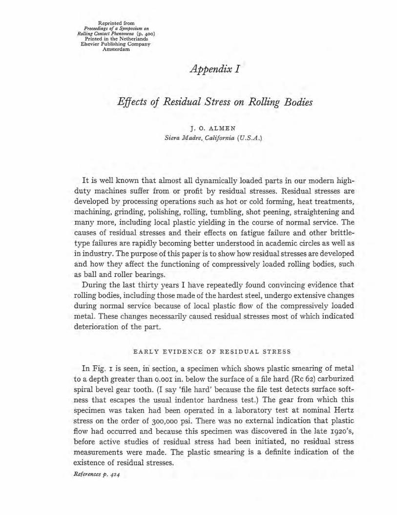
In Fig. r is seen, iri section, a specimen which shows plastic smearing of metal to a depth greater than o.oor in. below the surface of a file hard (Re 62) carburized spiral bevel gear tooth. (I say 'file hard' because the file test detects surface softness that escapes the usual indentor hardness test.) The gear from which this specimen was taken had been operated in a laboratory test at nominal Hertz stress on the order of 300,000 psi. There was no external indication that plastic flow had occurred and because this specimen was discovered in the late r92o's, before active studies of residual stress had been initiated, no residual stress measurements were made. The plastic smearing is a definite indication of the existence of residual stresses. Re[e,·ences p. 424
EFFECTS OF RESIDUAL STRESS ON ROLLING BODIES 40I
Fig. I. Section through carburized bevel gear tooth showing plastic flow of hard steel (Re 62).
Also in the late rgzo's, during inspection of hardened SAE 52roo steel rollers, of the type seen in Fig. 2, which were used in a friction drive mechanism at nominal Hertz stresses ranging from 150,000 to 300,000 psi. I found that the rollers were reduced in diameter as though b~· "·ear. The diameters of the rollers and their transverse radii of curvature had been accurately dimensioned which permitted precise determination of the metal presumably lost by wear. Since, however, there were no surface indications of wear, a test was devised in v.rhich nev·.r rollers were very thinly coated (est. o.oooor in.) with electro-deposited chromium. As long as this coating remained the roller surface could not be stained by a water solution of copper sulphate. After a long period of operation the plated rollers were again measured and their diameters were again reduced, but not by wear because the still intact chromium coating prevented copper staining. From this I concluded that local plastic flow of the hard metal had occurred, thereby reducing the roller diameters. Residual stresses were not measured.
Still in the late r92o's, during routine inspection of automobile rear axle parts after completing a standard dynamometer durability test, I found that the inner race of the ball thrust bearing supporting the pinion was permanently deformed. The deformation ,:vas clearly due to plastic flov.r of the race metal by the angular contact rolling balls. The resulting residual compressive stress acting against the
References p. 424

402 J . 0. ALMEN
I
·-$-· Fig. 2. Rollers made from SAE 52100 steel, Re 60-62 hardness, were found reduced in diameter as by wear after a few hours operation under nominal Hertz stress ranging from 150,000 to 300,000 psi. By applying thin chromium plate on the rollers and testing with copper
sulphate solution, the "wear" was found to be plastic flow of the hard steel.
ANGLE OF DEFORMATION
Fig. 3. This is an exaggerated view of the permanent set that occurred in inner race of an automobile rear axle pinion thrust bearing during a laboratory rear axle durability test. The inner race deformation was caused by the plastic flow of the race metal under the combined
radial and thrust loads of the bearing balls.
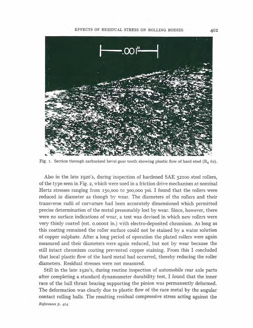
mner race as is seen in Fig. 3 was so great as to permanently deflect the race flange. The permanent deformation could be seen by placing a straight edge across the end of the bearing. The only bearing so measured was the upper double row type shown at left in Fig. 4.
The hypoid truck pinion seen in Fig. 5 shows the plastic fl°'v of the tooth surfaces that occurred during dynamometer durability tests . Such extensive plastic deformation without seizure (welding) was possible because of the then (about
_ I936) recently developed E. P. lubricants. The rippled markings suggest 'stickslip' friction, high temperature and residual compressive stress.
References p. 424
EFFECTS OF RESIIJCAL STRE SS O:'.\ ROLLING BODIES
Ill w I ~ 0.005--;=-----
z Q 0.004 -z
u... 0.003----~ 0
0.002- ~ -
~
fz w 2 w
0001 :
- ~
> 0 2 0
-
~ ------------ - ,--~
·- --- - - -- ·- --- --. I I ~ ,r ,r
- . ·-
Fig. 4.
Fig. 5 . Rippled hypoic1 pinion showing plastic thm of hard steel (Re 60-62).
INTENTIOKAL PRE ST RE SS I:'.\ G FOR ST RE N GTH AND FORMING
Residual stress measurements were not possible in the above cases because of high priority projects at General Motors Research Laboratorywhichrequiredall of my time. The only residual stress experiments of importance that I could perform before we began preparations for \ \' orld \\ · ar II were shot peening of production
References p. 424
J. O.ALMEN
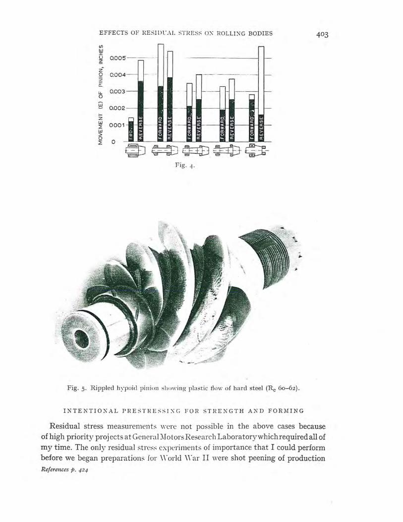
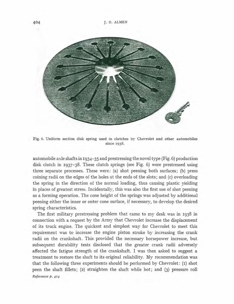
Fig. 6. Uniform section disk spring used in clutches by Chevrolet and other automobiles since 1938.
automobile axle shafts in 1934-35 and prestressing the novel type (Fig. 6) production disk clutch in 1937-38. These clutch springs (see Fig. 6) were prestressed using three separate processes. These v,1ere: (a) shot peening both surfaces; (b) press coining radii on the edges of the holes at the ends of the slots; and (c) overloading the spring in the direction of the normal loading, thus causing plastic yielding in places of greatest stress. Incidentally, this was also the first use of shot peening as a forming operation. The cone height of the springs was adjusted by additional peening either the inner or outer cone surface, if necessary , to develop the desired spring characteristics.
The first military prestressing problem that came to my desk v,ras in 1938 in connection with a request by the Army that Chevrolet increase the displacement of its truck engine. The quickest and simplest way for Chevrolet to meet this requirement was to increase the engine piston stroke by increasing the crank radii on the crankshaft . This provided the necessary horsepower increase, but subsequent durability tests disclosed that the greater crank radii adversely affected the fatigue strength of the crankshaft. I was then asked to suggest a treatment to restore the shaft to its original reliability. My recommendation was that the following three experiments should be performed by Chevrolet: (1) shot peen the shaft fillets; (2) straighten the shaft while hot; and (3) pressure roll
References p. 424
EFFECTS OF RESIDUAL STRESS o::,;; ROLLING BODIES
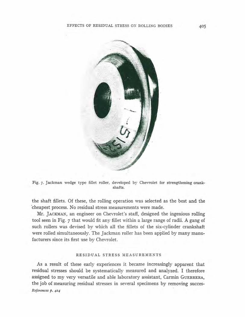
Fig. 7. Jackman wedge type fillet roller, developed by Chevrolet for strengthening crankshafts.
the shaft fillets. Of these, the rolling operation was selected as the best and the 'cheapest process. No residual stress measurements were made.
Mr. JACKMAN, an engineer on Chevrolet's staff, designed the ingenious rolling tool seen in Fig. 7 that would fit any fillet within a large range of radii. A gang of such rollers was devised by which all the fillets of the six-cylinder crankshaft were rolled simultaneously. The Jackman roller has been applied by many manufacturers since its first use by Chevrolet.
RESIDUAL STRESS MEASUREMENTS
As a result of these early experiences it became increasingly apparent that residual stresses should be systematically measured and analyzed. I therefore assigned to my very versatile and able laboratory assistant, Carmin GUERRERA, the job of measuring residual stresses in several specimens by removing succesReferences p. 424
j. O. ALMEN
sive layers of metal from the specimens, usings a hand hone. Progress was very slow because of the laborious method used for removing metal, but the results were satisfying. A formula was developed by which the residual stress could be calculated from the curvature data supplied by Mr. GuERRERA's measure men ts.
Some of the results of this initial venture in residual stress measurements are reported in papers1 that I presented before the Detroit Chapter of the American
Society for Metals in November, 1942. Residual stresses in ball or roller bearings were not studied by General Motors
Research Laboratory until 1944, when I organized a cooperative research project by General Motors Research Laboratories and New Departure Ball Bearing Division, General Motors Corp. I ts purpose was to measure residual stress in ball bearing races that might develop as a result of normal bearing testing operation in the New Departure Laboratory.
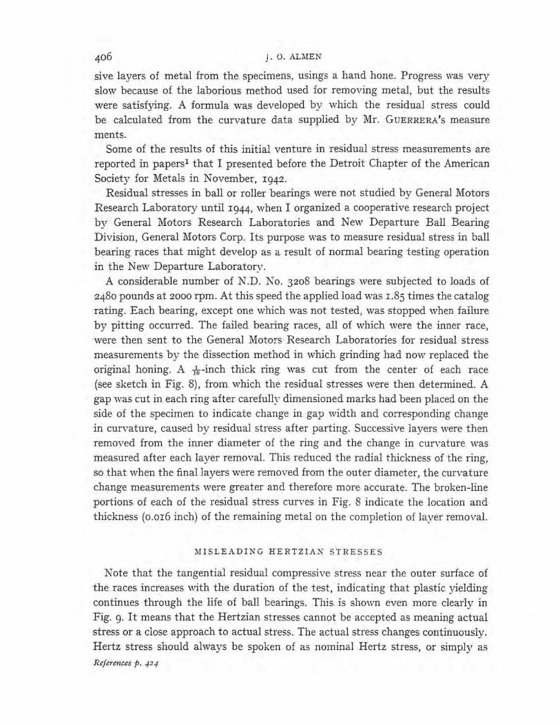
A considerable number of N.D. No. 3208 bearings were subjected to loads of 2480 pounds at 2000 rpm. At this speed the applied load was 1.85 times the catalog rating. Each bearing, except one which was not tested, was stopped when failure by pitting occurred. The failed bearing races, all of which were the inner race, were then sent to the General Moto!"s · Research Laboratories for residual stress measurements by the dissection method in which grinding had now replaced the original honing. A nr-inch thick ring was cut from the center of each race (see sketch in Fig. 8), from which the residual stresses were then determined. A gap was cut in each ring after carefully dimensioned marks had been placed on the side of the specimen to indicate change in gap width and corresponding change in curvature, caused by residual stress after parting. Successive layers ,:vere then removed from the inner diameter of the ring and the change in curvature was measured after each layer removal. This reduced the radial thickness of the ring, so that ,vhen the final ]ayers were removed from the outer diameter, the curvature change measurements were greater and therefore more accurate. The broken-line portions of each of the residual stress curves in Fig. 8 indicate the location and thickness (0.016 inch) of the remaining metal on the completion of layer removal.
MISLEADING HERTZIAN STRESSES
Note that the tangential residual compressive stress near the outer surface of the races increases ,:vith the duration of the test, indicating that plastic yielding continues through the life of ball bearings. This is shovm even more clearly in Fig. 9. It means that the Hertzian stresses cannot be accepted as meaning actual stress or a close approach to actual stress. The actual stress changes continuously. Hertz stress should always be spoken of as nominal Hertz stress, or simply as
References p. 424
EFFECTS OF RESIDUAL STRESS ON ROLLING BODIES
nominal compressive stress when applied to ball bearings, roller bearings, gear teeth, cams and the like.
The small residual compressive stress in the 'zero hours' specimen, i.e. the specimen that had not been tested, was probably developed by polishing. The high residual compressive stress in the bore of the bearing that had been operated I774 hours is, presumably, due to creeping of the race against the shaft. In contrast to the high surface residual stress developed in the bearing bore, the "residual stress developed on the surface of the inner race groove by the bearing balls is
l') w :c (..)
6
LLi (..)
it c: ROLLING ::, SURFACE ~-~ .... t-l z i=f Cl)
15
Fig. 8. Residual stress in ball bearing inner races by plastic deformation ( cold work)
during normal operation.
3
z rt) Q 2 rt) rt) .... (/) a: .... Iii ll:
~ Q O I ~ 0 c.. ct . a: ... ..:
<ri
"' . z 0 in z .... ... .010 .0 5
FAILED
NO FAILURE NO FAILUlE FAILED FAILED
-STRUCTURE SAME -STRUCTURE. ~ED
.030 .035
DEPTH BELOW BALL RACE • IN.
Fig. g. Tangential trapped stresses in inner race of ball bearings.
very low. A short distance belo\v the surface it increases to a high value and then at greater depth it again decreases. The actual stress is, of course, the algebraic sum of the residual stress and the Hertzian stress, but since the residual stress is rarely known and the Hertz stress cannot be calculated because the shape of the groove has changed the actual stress cannot be known.
EFFECT OF KEGATIVE SLIDING
The probable cause of the very low residual compressive stress near the surface of the specimens from which the diagrams Fig. 8 and Fig. 9 were constructed is believed to be the high sliding friction of the bearing balls against the bottom of
References p. 424

]. 0. ALMEN
,, ;~~:;,, · . _ ..... :.-( ·: 1/10 inch ~ - ~ ~v~..... ". ::_ ;if ., . · 8
Fig. 10. Typical ball bearing failure. A - Spalled area on inner race of ball bearing. Note upward extension of original spall by succession of breaks due to sliding friction of balls. B - Cross section through bearing race near center of spall. Such spalls or pits are fatigue fractures originating in subsurface defects where local plastic yielding has developed residual
tensile stress.
the inner race grooves. Let us consider how local plastic yielding can occur in an inner bearing race. Since each ball is in pressure contact with the race over a considerable arc, true rolling can occur only at a greater radius than the bottom of the inner race groove. Sliding under great pressure must, therefore, occur at greater and lesser radii than the radius of true rolling. As is indicated in Fig. ro, the direction of sliding at the bottom of the inner race groove is opposite to the direction of ball rolling, while at greater radii than the race 'pitch circle' sliding is in the same direction as the rolling of the balls.
It appears that the friction from negative sliding of the bearing balls on the portion of the races where the residual stresses were measured tended to develop residual tensile stress, as was indicated by the reports of ,,, A Y 2, MELDAHL 3 AND
\VARREN4, and the residual compressive stress caused by pressure rolling of the balls tended to develop residual compressive stress. The net effect of these opposing forces was residual compressive stress ranging from rooo to r7,ooo psi at the specimens surfaces. However, the effect of sliding decreased rapidly with depth as compared to the compressive effects of rolling. This is shown by relatively high magnitude residual compressive stresses at depths ranging from 0.004 in. to o.oro in.
The publications referred to above 2- 4 relate to a similar condition of surface sliding in a direction opposite to the direction of rolling that occurs below the pitch line ( dedendum) of gear teeth. This action is believed by the authors to be a cause of gear-tooth pitting. Experiments with gears and rollers have seemingly
References p. 424

EFFECTS OF RESIDUAL STRESS ON ROLLING BODIES
supported negative sliding as a cause of pitting by first developing cracks through high frictional tensile forces. None of the published data included residual stress measurements and no frictional surface cracks have been found in ball-bearing races unless deep pits had first been formed from other causes.
The caption of Fig. IO directs attention to a succession of cracks in the upper half of the spalled area of a ball bearing inner race. These cracks were caused by the tangential force of friction from negative sliding of the balls against the race as is indicated by arrows in the photo and as has been described above. Each crack began near the upper edge of a pit in undamaged metal and grew in length and depth until the wall of the cavity broke away, thus increasing the tangential length of the spall.
FATIGUE CRACKS BELo ·w BEARING SURFACES
Ball-bearing manufacturers agree that pits and cavities in their bearings begin as fatigue cracks extending from subsurface defects such as inclusions and voids. These cracks grow outward at acute angles, thus detaching metal to form cavities or pits. In Fig. Io the lower t or l of the spall presumably grev.r from a subsurface defect and later its area was extended upward, as seen in the photo, by successive cracks adjacent to its upper wall.
It is probable that the effects of negative sliding vary with the conditions of the test applied, such as velocity, unit load, metal hardness and lubrication.
Negative sliding also occurs on railway wheels and rails because the two wheels on each axle must rotate at the same angular velocity while, on curves, the upper (outer) rail has a greater length than the low rail. Negative sliding of the low rail wheel \\rhile, for equal friction, positive sliding on the high rail occurs. How-. ever, serious damage from shelling occurs only on the high rail; a problem that will be discussed later in this paper.
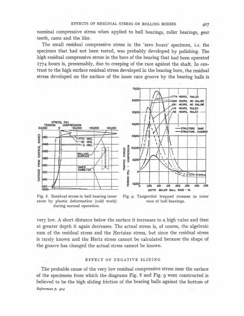
Residual stress measurements are available for only one location of only the radial-type ball bearing shown in Fig. 8. The residual stress distribution in angular contact and in axial contact ball bearings are still unknown, as is also the residual stress pattern in bearing balls except the radial-loaded specimen seen in Fig. II.
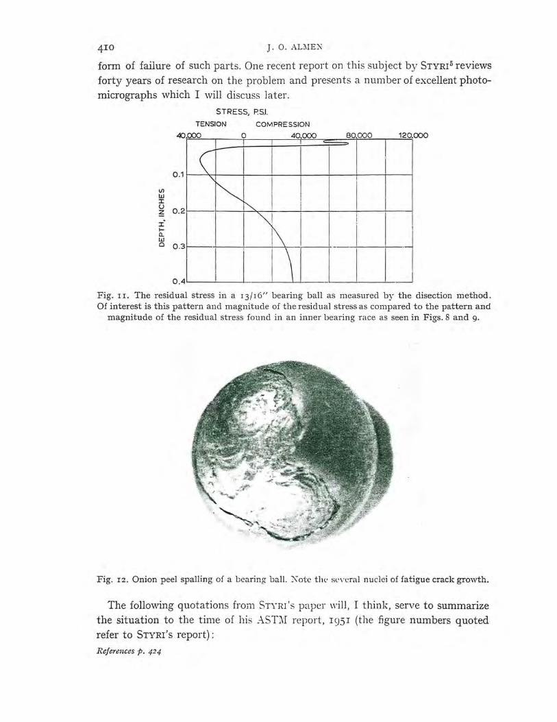
Because of its random axis of rotation, any point on a bearing ball experiences all conditions of contact: positive sliding, negative sliding and 'true' rolling. The measured residual stress pattern (Fig. rr) is very interesting because it presumably represents the average of numerous possible residual stress patterns. The onionpeel spalling of the ball (Fig. IZ) represents the end result of a ball residually stressed as seen in Fig. II. The conditions under which onion-peel spalling occurs will be discussed later.
Manufacturers and users of ball and roller bearings have long sought the cause of and a remedy for pitting of bearing races, balls and rollers, the most common
References p. 424
4IO J. 0. ALi\IEN
form of failure of such parts. One recent report on this subject by STYRI5 reviews forty years of research on the problem and presents a number of excellent photomicrographs which I will discuss later.
STRESS, P.S.I.
TENSION
40CXX>
COMPRESSION
0 40CXX)
V1 w J: u
; 02~
IL.I
Cl 0 .3 +1---+.---+---J I I
120,000
I I
I I
wj Fig. 11. The residual stress in a 13/16" bearing ball as measured by the disection method. Of interest is this pattern and magnitude of the residual stress as compared to the pattern and
magnitude of the residual stress found in an inner bearing race as seen in Figs. 8 and g.
Fig. 12. Onion peel spalling of a bearing ball. Kotc th e se\"l:ral nuclei of fatigue crack growth.
The following quotations from STYRI 's paper will, I think, serve to summarize the situation to the time of his ASTl\1 report, 1951 (the figure numbers quoted refer to STYRI's report):
References p. 424
EFFECTS OF RESIDUAL STRESS ON ROLLING BODIES 4II
'Numerous fatigue tests on ball bearings have shown that the lives of individual bearings, before failure by spalling or flaking, show a scatter over a wide range of I to 50 or more.'
(This shows that life variation of ball bearings is greater than the variations found in other machine parts.)
(STYRI's Fig. r shows no fatigue endurance limit up to 2,000,000,000 revolutions, showing again that in some manner the stress range differs from conventional fatigue specimens, perhaps the actual stress is slowly increasing and erratic.)
'Obviously there is a weakest spot in the track that provides the starting point for the failure.
'It has not been possible to get noticeable reduction in scatter by using the cleanest steel obtainable. In all tests the failure starts from one point or at most from two or a very fevir points ...
'It is generally considered that slag inclusions are major defects from which fatigue failures start.
'It is of interest to note that fatigue lives of the vacuum melted steel are considerably greater than for standard SAE 52100 steel for hardness equal to or greater than 60 Rockwell C.
'The author [Dr. STYRI] reported in 1925 and later that the flaking usually started belov.r the surface where the ball track was located, and the cracks grew from there to the surface. A number of times since then this observation has been verified by taking sections of races crosswise or lengthwise of the ball tracks at points where no cracks were observable on the surface after prolonged fatigue test.
'In Fig. ro (a), (c) and (d) severe strain lines extend from slag inclusions at depths below the surface up to 0.03 inch. It is of interest to note that the strain lines are not in any definite directional relation to the surface; some are at 45 deg. ; others parallel to it. Fig. ro (b) shows a crack without the presence of slag inclusions, essentially parallel to the surface, and 0.008 inch below. Fig. II (a) and (b) show start of cracks at slag inclusions.' (I suspect that in Fig. ro (b) the section missed the inclusion .)
'It is also very interesting that these severe strain lines often occur at a level below the dark etching region which has been subjected to heavy cold working. It is well known that many fatigue failures start from slag inclusions of various sizes, and such inclusions are therefore considered to be at least contributory to failures . Obviously they are dangerous only when they are located in a spot which is subjected to relatively heavy alternating shear stresses or tensile stresses.
'Elimination of certain obvious defects such as larger slag inclusions improves the fatigue life without reduction of the scatter.
References p. 424
4r2 J. 0.ALMEN
'If reduction of local weaknesses can be obtained, a substantial increase in life of ball bearings should be possible.
'Further tests on vacuum-melted steel are under way.'
CAUSE OF SPALLING FATIGUE CRACKS
From previous experience I knew that fatigue failures could grow only by tensile stresses, but the tensile stress in bearing contacts, as calculated by HERTZ
and others, was too low to cause fatigue cracks. After much study of the Styri photomicrographs it became clear that micro residual tensile stresses of great magnitude were developed in the steel adjacent to the slag inclusions, voids and similar defects .
As mentioned in the above quoi ations and as is seen in Figs. r3 and r4, the markings, called 'strain lines' by STYRI (known as grey lines by New Departure), extend from subsurface defects. These lines are actually caused by local compressive plastic flow. Plastic flow is localized because of local weakness in the vicinity of inclusions and adjacent metal is therefore stressed beyond its compressive elastic limit, whereas the greater volume of metal surrounding the strain lines is stressed below the elastic limit. It is well known that macro local plastic flow develops residual stress of opposite sign to the stress that causes the plastic flov,1 • For the same reason residual stress is developed, even though the affected metal is so small as to be almost or entirely invisible to the unaided eye. The plastic deformation seen in Fig. r3 was caused by repeated compressive loads on metal that was locally weakened by an inclusion as successive balls rolled over the defect. In this case the defect was 0.025 in. below the surface of a bearing race. The deformed metal seen in Fig. r4 likewise was caused by successive loads acting on weakened metal, but in this case the defect was found in a baJl at a depth of 0.006 in. I have shown elsewhere that the elastic limit of steel under repeated loads may be approximately i that of the static elastic limit.
Residual tensile stress develops in such local, compressively deformed metal because the adjacent sound metal does not suffer such plastic deformation and it therefore recovers elastically ·when the external load is removed. The drastically deformed metal does not ·so recover but is forcibly restored to nearly its original dimensions by the greater volume of elastically recovered metal. The result is high-magnitude residual tensile stress adjacent to the inclusion. The stress in this small volume of steel ranges from high-magnitude residual tension when no external load is acting to compressive stress when the external load is applied. These repeated tensile stresses eventually result in fatigue cracks which grow at acute angles to the surface and form the well-known but variously named pits, flakes, spalls or cavities which destroy ball bearings, roller bearings, cams, railroad rails and probably gear teeth.
References p. 424

EFFECTS OF l{E SIDL\L STEESS O:-.: IWLLJ :\"G BODIES 413
Fig. 13. Internal fatigue cracks de\·elop in ball bearing race from residual tensile stress caused by local plastic deformation of r ace under compressive load of balls .
Fig. 14. Photomicrograph sh, i,Yi 11.g the " lill ch· .. llf the "moth " as an incl11sion or void 0 .006"
below the surface of a hall lie:1rin .g li;ill. Th l' "\\·ings· · of the "moth·· are local plastically compressed areas res11lting from J,:c; tl \\·L·ak nl'ss adjacent to the defect. Local compressive plastic flow ca uses res id 11a I tensile st res,;. Thl' t, ,ta I ,;tress in these areas is therefore compressive while a loaclecl liall is acting ,m till' dd11rmed metal ancl tension \\'h en the external load has passed. The res11Jt is fatigu e f:1ilun· beginnin g in the cldect and gro\\"ing to the surface in the
form ll f ,I pit.
References p. -P./

J. 0.ALMEN
I call your attention to a second sub-surface defect near the left edge of Fig. r3 which, because of its small size (.00025 in.), did not weaken the adjacent metal enough to cause local plastic flow.
The theory that ball-bearing pits or spalls are caused by local micro-scale plastic flow extending from inclusions and voids is in agreement with the fatigue behavior of bearings. The ·wide scatter of 50 to r in fatigue durability is consistent with variations in the number of defects and their size and depth in bearings. A bearing having many defects of relatively large size and near the surface would fail by fatigue in a very short time, whereas a bearing having few defects of relatively small size and great depth would fail only after a very long period of service.
Vacuum-melted steel would be expected to have relatively smaller inclusions and voids which would account for its superiority.
The photomicrograph of Fig. r3 is reproduced by courtesy of SKF Industries (see also ASTM Proceedings, 5r, pp. 692, 693 and 695 for additional photomicrographs by SKF).
The photomicrograph of Fig. r4, which is reproduced by courtesy of New Departure Division, General Motors Corporation, was made from a ball taken from a complete bearing after operating 200 hours in a laboratory test under a load equal to r8o% of its catalog rating.
RE SUL TANT OF BENEFICIAL RESIDUAL STRESSES
Early in vVorld ,,,ar II one of the problems that demanded quick solution was failure of transmission gears in the large trucks used for transporting iron ore from the Minnesota mines to railway cars. This was a very severe service because is was necessary to haul the heavy loads from the mine pit to the surface. At the manufacturer's request for a remedy. I recommended some minor design changes and also that all gears be shot peened. The gears were carburized and therefore very hard so suitable shot-peening intensity (o.orz) was specified.
The peened gears functioned very satisfactorily and the tooth failure trouble was no longer a problem, but the Chief Engineer, T. Backus, was disturbed by chipping of corners of the gear teeth. Fig. r5 shows the cause of the chipping. At point B shot peening developed biaxial residual compressive stress on the two surfaces which form a sharp corner where the two stressed planes converge. The resultant residual stress from the compressively stressed layers was outward, as is indicated by an arrov.r, and very little additional force was needed to chip off such corners, as is shown at B'. In fact, all that was necessary was to tap the corner with the back of a pocket knife. Similarly, chipping occurred at point A because of the outward resultant residual stress.
This also explains why it is necessary to round all sharp corners on nitrided
Refel'enr.es p. 424

EFFECTS OF RESIDUAL STRESS ON ROLLING BODIES
Fig. 15 . Chipping of external corners. This occurs in very hard steel when the tensile stresses that are induced by residual compressive stresses become sufficiently great.
machine parts in which the residual compressive stress approaches r40,ooo psi. Similarly, sharp corners of all carburized and shot-peened parts, not only carburized gear teeth, are easily chipped.
I suggest that, for classroom demonstrations, a few specimens such as sharp cornered square or triangular steel bars of i or l inch section be nitrided, another similar group be carburized and shot peened. Such specimens can be used to shovv the ease with which the corners can be chipped. Some similar specimens, except that their sharp corners should be slightly rounded before hardening, should also be made to sho,v how chipping can be prevented.
Returning now to Fig. r5: note that a third system of stresses is shown at the root of a gear tooth and that the resultant stress is now inward, not outward as at A and B. Here there is no danger of spalling.
Let us now consider the case of ball-bearing races. Any residual compressive stress that is developed by the bearing balls in the outer race ball groove will produce an inward-acting resultant force ,vhether measured in a plane of the bearing axis or in a plane perpendicular to the axis. On the inner ball race the residual
. compressive stress will produce inward-acting resultant forces when measured in a plane of the bearing axis but outward acting resultant forces in a plane perpendicular to the bearing axis. However, since the latter is of lower magnitude than the stress transverse of the ball groove, spalling does not originate from such stresses
References p. 424
J. O.ALMEN
in either race. The resultant of residual compressive stresses in bearing balls is always outward, as is also true of tangential stresses in roller-bearing inner races and in roller-bearing rollers. (See Fig. rz for onion-peel spalling from the surface of a ball and see also illustrations published by BUCKINGHAM AND TALBOURDET. 6
In this publication, Figs. r47, r50, r53, r54, r6z and r63 show separations of surface layers which are clearly due to the outward resultant of residual stresses after a crack or cracks were initiated in defects such as are seen in Fig. r3 or similar stress raisers. As in ball and roller bearings, fractures begun in zones of weakness, such as inclusions and voids, were due to local plastic compressive yielding; great residual tensile stresses occurred upon each removal of the external load. A local crack having started, the relatively weaker separating stress from the outward acting resultant was sufficient to continue the crack as seen in the above illustrations.
'SHELLING' OF RAILWAY RAILS
vVe come now to the fatigue failures in railway rails as is seen in Figs. r6 and r7. The specimen in Fig. r7 is, unfortunately , a bit confusing because it shows a compound fracture, i .e. a transverse fatigue crack as well as a longitudinal fatigue crack. Of these I shall first discuss the longitudinal crack, which, in railway parlance, is knovm as 'shelling', meaning that a layer of steel -1- in. or more in thickness becomes detached from the surface of the 'high' (outer) rail on curves. The beginnings of such detachments are doubtless the same as the beginnings of spalls in ball bearing races seen in Figs. r3 and r4; that is, subsurface defects such as inclusions, voids and the like provide local residual tensile stress of sufficient magnitude to start micro fatigue cracks. The continuing longitudinal growth of such micro-scale cracks to form large-scale cracks, known as shelling and seen in Fig. r7, is the separating force R seen in Fig. r6. R is the resultant force of residual compressive stresses that are developed by plastic flow of the rail surface metal by the horizontal centrifugal load C of the ,vheel flange and the vertical wheel load TV.
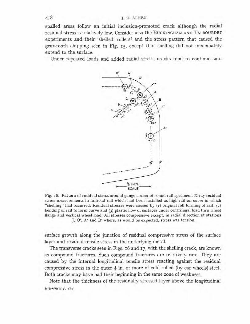
Fig. r8 shows the pattern of residual stresses, as measured by NORTON of M.I.T. for the Association of American Railroads\ in an unfailed portion of a rail that had developed 'shelling'. It is seen that at Stations B', A', O' and J the radial residual stresses are tension and that all other measured stresses are compressive. This confirms the residual stress pattern shown in Fig. r6. Although the tensile stress magnitudes are low, it must be appreciated that the points measured do not represent the maximum and that crack growth does not require high stress. Once started, a crack is a very severe stress-raiser, and growth of the crack needs little additional help.
Much the same situation occurs in 'onion-peel' spalling of bearing balls. Large
References p. 424

EFFECTS OF RESIDUAL STRESS ON ROLLIN(; BODIES
w WHEEL
Fig. 16 "Shelling" (longitudinal fatigue fracture) in outer rail on curves is caused by tensile residual stress (R), a resultant of residual comi:ressive stress from plastic transverse flow of
rail head by vertical load (\V) and centrifugal flange load (C) .
: . ;.""J. "'" - ... ~ _ ., _,_,.: - •
" - ,___.:c..., . __ o-, . ') • ~ t.;
· , .. ,- ... _., ..
Fig. 17. Transverse fatigue crack (F) is clue to tensile reaction (T-T) from residual compressive stress (C - C) ca used by plastic flow of rail surface under vertical ancl horizontal loads of car
wheels.
Rcfcrc11ccs p. 42-1
J. O.ALMEN
spalled areas follow an initial inclusion-promoted crack although the radial residual stress is relatively low. Consider also the BUCKINGHAM AND TALBOURDET experiments and their 'shelled' rollers6 and the stress pattern that caused the gear-tooth chipping seen in Fig. r5, except that shelling did not immediately extend to the surface.
Under repeated loads and added radial stress, cracks tend to continue sub-
B' A'
\\ -\-~· ----·-- ~ ·?®,.,_ ii"'- ./ r
~I I Q /
s.o ~; ~~; . , A
'I,' J~: ;IQ), / B H--0't,, />· ·o~,z-z!:> __ .C
K '-~f;l,. ~ ~ ·--.t:..:>\ e- !',."' .>
---
.!<Y .,,. , t -'.Z!'>·;s,''
/0 ,,.,,"? ~~
------
bw -128.7
j / D
tW -J21.0
I I I I I I I -;
_., ) ------ .
Y2 JNCH----+J f--- SCALE '
Fig. 18. Pattern of residual stress around gauge corner of sound rail specimen. X-ray residual stress measurements in railroad rail ·which had been installed as high rail on curve in which "shelling" had occurred. Residual stresses were caused by ( 1) original roll forming of rail; ( 2) bending of rail to form curve and (3) plastic flow of surfaces under centrifugal load thru wheel flange and vertical wheel load. All stresses compressive except, in radial direction at stations
J, O', A' and B' where, as would be expected, stress was tension.
surface growth along the junction of residual compressive stress of the surface layer and residual tensile stress in the underlying metal.
The t_!ansverse cracks seen in Figs. r6 and r7, with the shelling crack, are knO\vn as compound fractures. Such compound fractures are relatively rare. They are caused by the internal longitudinal tensile stress reacting against the residual compressive stress in the outer t in. or more of cold rolled (by car wheels) steel. Both cracks may have had their beginning in the same zone of weakness.
Note that the thickness of the residually stressed layer above the longitudinal
References p. 424
EFFECTS OF RESIDUAL STRESS ON ROLLING BODIES
crack is greater below the wheel load l-V than was caused by the centrifugal load C. This difference in plastic flow under the two applied loads is also reflected in the angle of the longitudinal crack, which is 65°-70° from horizontal. This could be due to the load magnitude alone or perhaps also to the relative amount of sliding of the wheel surface and its flange.
NEGATIVE SLIDING OF WHEELS ON RAILS
Since two wheels are fixed on opposite ends on the same axle and since, on curves, the two wheels must roll at the same velocity while travelling different distances, considerable sliding must occur. The sliding of the 'high' ( outer) wheel is in the same direction as its rolling, whereas the sliding of the 'low' wheel is opposite to its direction of rolling. Because of this difference in the direction of sliding the resulting plastic flow pattern, and therefore the residual stress, even under the same load ·will be quite different from those seen in Figs. 8 and g.
I have no remedy to propose other than increased rail hardness, which would also be helpful in reducing transverse fissures but perhaps at increased cost and straightening trouble. Also, hard rails should be prestressed by shot peening to prevent failure from lo,;v-temperature brittleness.
Prevention of low-temperature brittleness by shot peening or the like should be given more attention because many machine parts used in cold climates are now limited in hardness by fear of cold brittleness.
PRESTRESSING OF RAILCAR WHEELS
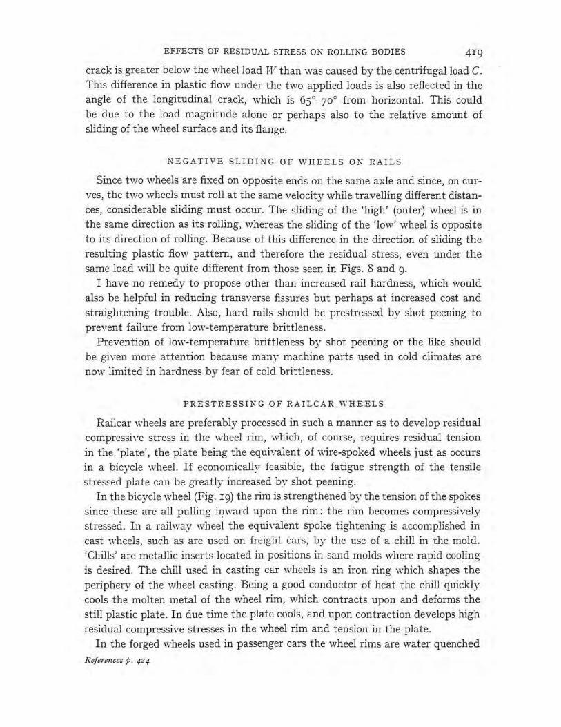
Railcar ,vheels are preferably processed in such a manner as to develop residual compressive stress in the wheel rim, which, of course, requires residual tension in the 'plate', the plate being the equivalent of ,vire-spoked wheels just as occurs in a bicycle wheel. If economically feasible, the fatigue strength of the tensile stressed plate can be greatly increased by shot peening.
In the bicycle wheel (Fig. 19) the rim is strengthened by the tension of the spokes since these are all pulling inward upon the rim: the rim becomes compressively stressed. In a railway ,vheel the equivalent spoke tightening is accomplished in cast wheels, such as are used on freight cars, by the use of a chill in the mold. 'Chills' are metallic inserts located in positions in sand molds where rapid cooling is desired. The chill used in casting car wheels is an iron ring ,;vhich shapes the periphery of the wheel casting. Being a good conductor of heat the chill quickly cools the molten metal of the wheel rim, which contracts upon and deforms the still plastic plate. In due time the plate cools, and upon contraction develops high residual compressive stresses in the wheel rim and tension in the plate.
In the forged wheels used in passenger cars the wheel rims are water quenched
References p. 424
420 J . O. ALMEN
from a high ·temperature and therefore contract and plastically deform the still plastic plates. Later, as each plate cools, its thermal contraction places the wheel rim in compression and the plate in tension. This residual stress eficct seems not to have been understood by wheel manufacturers or railway metallurgical or design engineers, the above described pro~essing having been applied on the theory that the wheels were hardened and toughened by ra::_Jid cooling. High
Fig. 19. Railway car wheels strengthened by residual stress. The thermally induced residual stress pattern in R.R. car wheels closely resembles spoke and rim stresses in bicycle wheels .
. 020 .040 .060 MACHINE CUT CLOSING, INCHES
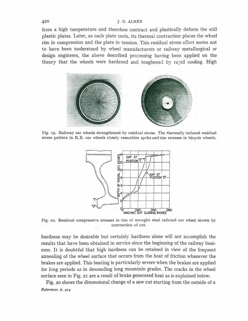
Fig. 20. Residual compressive stresses in rim of wrought steel railroad car wheel shown by contraction of cut.
hardness may be desirable but certainly hardness alone will not accomplish the results that have been obtained in service since the beginning of the railway business. It is doubtful that high hardness can be retained in view of the frequent annealing of the wheel surface that occurs from the heat of friction whenever the brakes are applied. This heating is particularly severe when the brakes are applied for long periods as in descending long mountain grades. The cracks in the wheel surface seen in Fig. 2r are a result of brake generated heat as is explained below.
Fig. 20 shows the dimensional change of a saw cut starting from the outside of a
References p. 424
EFFECTS OF RESIDUAL STRESS ON ROLLING BODIES 42I
railcar wheel and progressing inward. The changing dimensions of the saw slot as the cut progressed inward from the wheel rim were measured by two strain gauges placed across the cut at points o and r. The gauge readings are recorded by the two curves in the graph. It is seen that the saw slot closed a maximum of 0.055 in. in response to the residual compressive stress in the rim. Other measurements have been made, notably by the Denver and Rio Grande Railway, showing
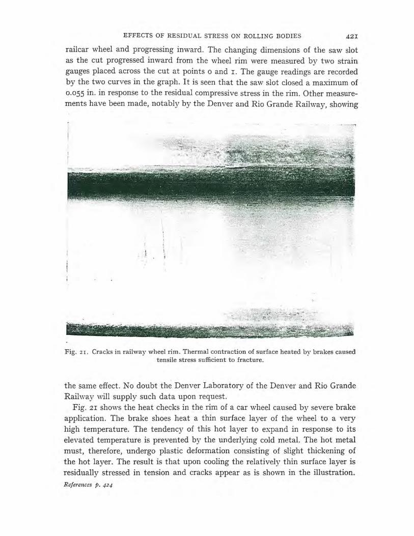
Fig. 21. Cracks in railway wheel rim. Thermal contraction of surface heated by brakes caused tensile stress sufficient to fracture.
the same effect. No doubt the Denver Laboratory of the Denver and Rio Grande Railway will supply such data upon request.
Fig. zr shows the heat checks in the rim of a car wheel caused by severe brake application. The brake shoes heat a thin surface layer of the wheel to a very high temperature. The tendency of this hot layer to expand in response to its elevated temperature is prevented by the underlying cold metal. The hot metal must, therefore, undergo plastic deformation consisting of slight thickening of the hot layer. The result is that upon cooling the relatively thin surface layer is residually stressed in tension and cracks appear as is shown in the illustration.
References p. 424
422 J. 0. ALMEN
These are equivalent to the cracks that occur in other machined parts, such as metallic molds for casting metal, the bore of rapid fire guns and surfaces which have been finished by severe grinding.
CRACKS IN CAR WHEELS
The most interesting thing about these cracks is that they rarely propagate to catastrophic failure, the reason being that deeper material is still residually stressed in compression, and fatigue cracks cannot propagate into compressively stressed metal. These and many other specimens tell us that fatigue failures are tensile failures, and that a layer of residual compressive stress in the path of a
Crack origin
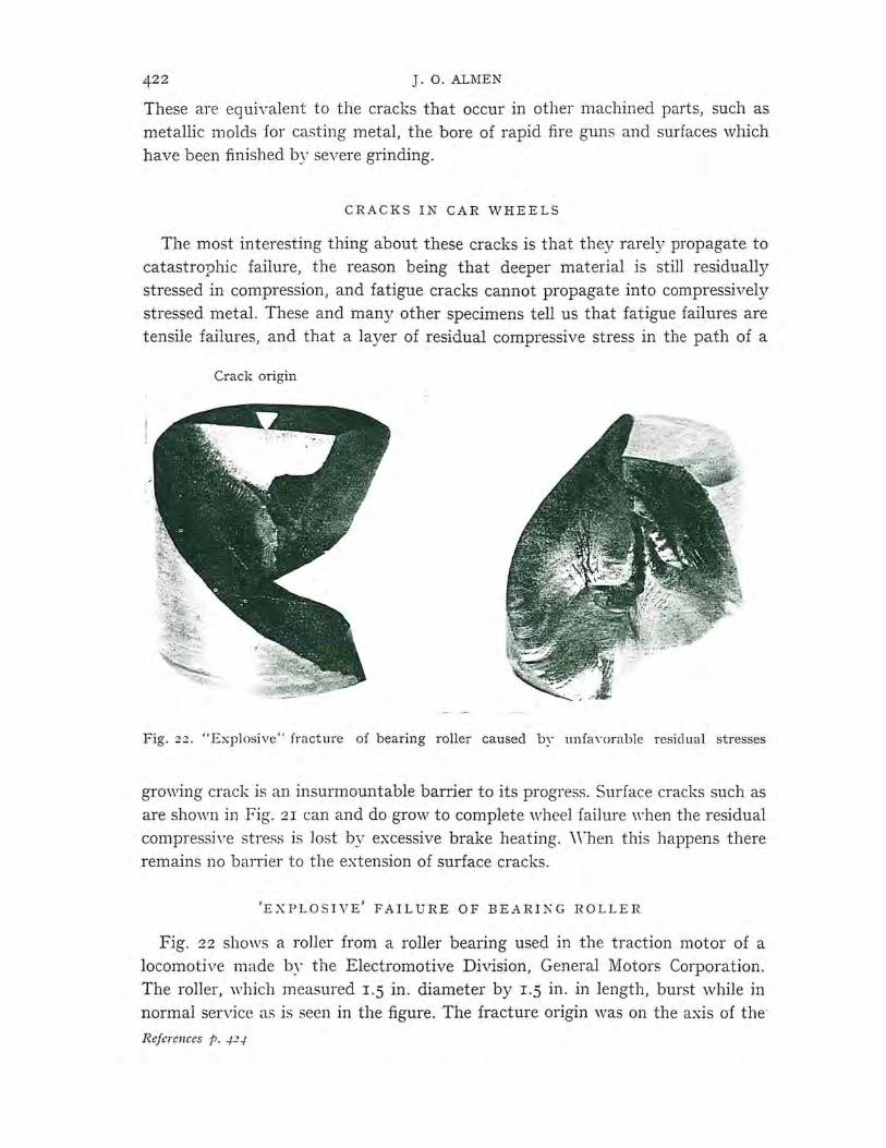
Fig. 22 . "Explosive" fracture of bearing roller caused bY unfan>rable residual stresses
growing crack is an insurmountable barrier to its progress. Surface cracks such as are shown in Fig. 21 can and do grov,, to complete wheel failure when the residual compressive stress is lost by excessive brake heating. \ Vhen this happens there remains no barrier to the extension of surface cracks.
'EXPLO S I V E' FAILURE OF BEARIKG ROLLER
Fig. 22 shows a roller from a roller bearing used in the traction motor of a locomotive made by the Electromotive Division, General Motors Corporation. The roller, which measured r.5 in. diameter by r.5 in. in length, burst while in normal service as is seen in the figure. The fracture origin was on the axis of the
References p . ..P-!
EFFECTS OF RESIDUAL STRESS ON ROLLING BODIES
roller at its upper end as is seen at the left. The bearing was made from a carefully selected, high grade, deep hardening steel and its failure presented a very serious and, to me, interesting problem.
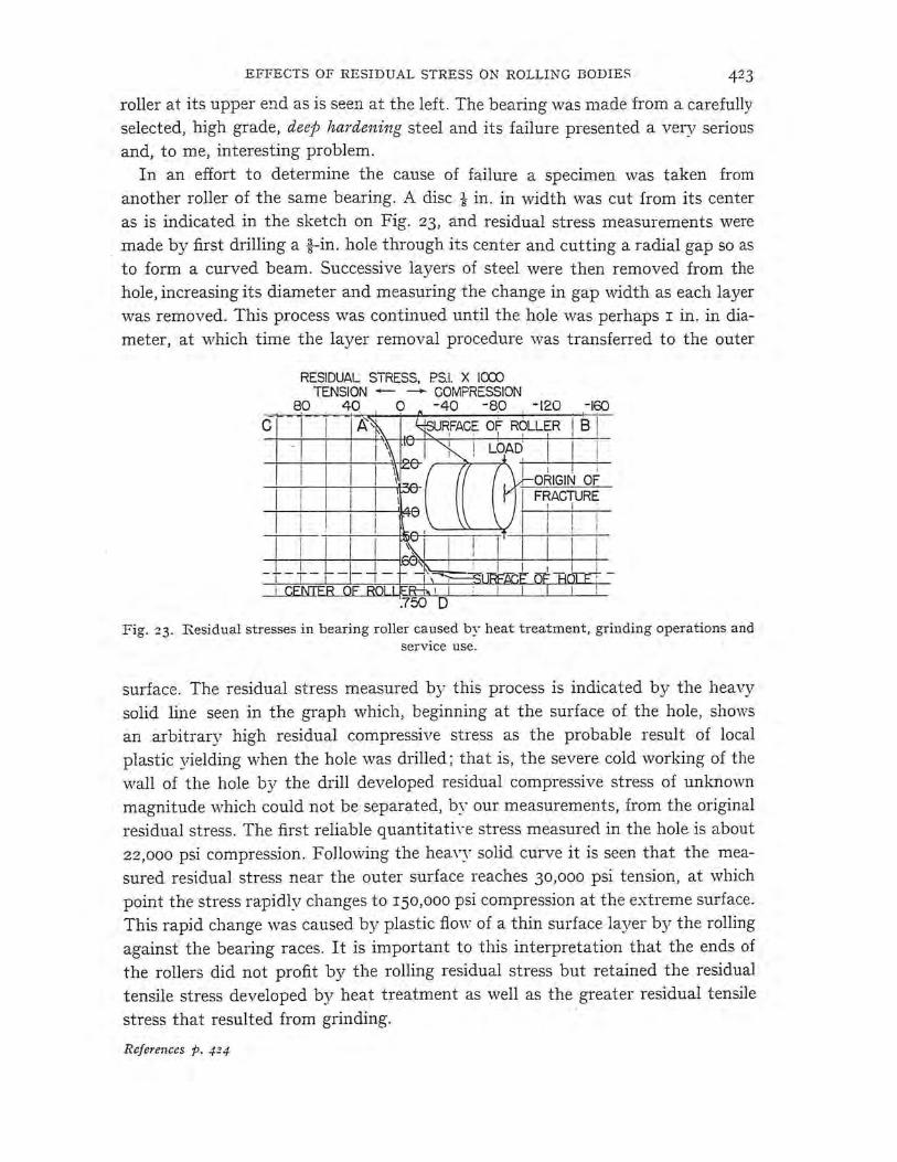
In an effort to determine the cause of failure a specimen was taken from another roller of the same bearing. A disc t in. in width was cut from its center as is indicated in the sketch on Fig. 23, and residual stress measurements were made by first drilling a i-in. hole through its center and cutting a radial gap so as to form a curved beam. Successive layers of steel were then removed from the hole, increasing its diameter and measuring the change in gap width as each layer was removed. This process was continued until the hole was perhaps I in. in diameter, at ,,vhich time the layer removal procedure was transferred to the outer
RESIDUAL STRESS, P.S.I. X !CXX) TENSION - ---+- COMPRESSION
8.0 4.0 Q -40 -s.o -120
c
I . I ORIGIN OF FRACTURE
I I :
I I
Fig. :23. Residual stresses in bearing roller caused by heat treatment, grinding operations and service use.
surface. The residual stress measured by this process is indicated by the heavy solid line seen in the graph which, beginning at the surface of the hole, shows an arbitrary high residual compressive stress as the probable result of local plastic yielding when the hole was drilled; that is, the severe cold working of the ·wall of the hole by the drill developed residual compressive stress of unknown magnitude which could not be separated, by our measurements, from the original residual stress. The first reliable quantitatiYe stress measured in the hole is about 22,000 psi compression . Following the heavy solid curve it is seen that the measured residual stress near the outer surface reaches 30,000 psi tension, at which point the stress rapidly changes to r50,ooo psi compression at the extreme surface. This rapid change was caused by plastic flow of a thin surface layer by the rolling against the bearing races. It is important to this interpretation that the ends of the rollers did not profit by the rolling residual stress but retained the residual tensile stress developed by heat treatment as well as the greater residual tensile
stress that resulted from grinding.
References p. 424
424 J . O.ALMEN
DANGERS OF DEEP-HARDENING STEEL
Paralleling the heavy solid line is a broken line which indicates · the probable residual stress prior to drilling the l in. hole and prior to operating of the bearing. The broken line extends an indefinite distance leftward at the surface of the roller. This is to indicate the residual tensile stress that was induced by the finishgrinding operation. This residual tensile stress in the cylindrical surface was later converted to residual compressive stress by pressure rolling against the bearing races, but the original residual tensile stress was retained on the ends of the rollers. It is this stress that was retained in the surface metal at the roller ends which triggered the explosive fracture. Added to the surface residual tensile stress was the transverse tensile stress from the applied compressive load shown by arrows. A crack having started, its growth inward was due to the applied load plus the deep residual tensile stress.
In passing, it is important that we compare the surface residual stress that developed in the subject roller ,vith the surface residual stress that developed in the ball-bearing races (Figs. 8 and 9). The difference in these residual stress patterns is probably due to the almost true rolling of the cylindrical roller vs. sliding opposite to the direction of rolling in the ball bearing.
The principal point of interest is the nature of the internal residual stress shown by the curve A-D (Fig. 23). The formation of martinsite in steel increases its volume. In deep-hardening steel such as was used in these bearing rollers, martinsite transformation occurred completely through the rollers but not at the same time; that is, martinsite was first formed in the surfaces and progressed slowly to the center of the r.5 in. rollers as the temperature decreased. The delayed increase in volume in the core of the roller provided ouhvard pressure. This applied tensile stress on the outer metal and, of course, corresponding compressive stress in the core as is shown by the residual stress measurements in Fig. 23. These r.5 in. bearing rollers would have been much stronger had they been made of clean, plain, medium carbon steel, in which case the residual stress would have been reversed from that shown in Fig. 23 .
REFERENCES
I J. 0. ALMEN, Peened surfaces improve endurance of machine parts, flt[ etal Prog1' ., four parts: February, May, August and September, 1943.
2 S. \VAY, Pitting due to rolling contact, T1'ans. AS]\tJE, 57 (1935) A 49. 3 A. MELDAHL, The Brown-Boveri testing apparatus for gear-wheel material, Enginee1'ing,
July 21, 1939. 4 G. B. \VARREN, Discussion of Earle Buckingham's ASME Paper, "Surface fatigue of plastic
materials", A SME Trans., 66, No. 44 (1944) 306. 5 H . STYRl, A STM Proc., 51 (1951) 682. 6 E. BucKINGHAM AND G. J. TALBOURDET, Mechanical Weai·, American Society for Metals, 7 Letter dated May 18, 1945, from G. M. MAGEE of Association of American Railways
addressed to Members, Subcommittee II, Area Rail Committee.