appendix h transmission system …. single-line diagram showing applicable equipment such as...
TRANSCRIPT

APPENDIX H TRANSMISSION SYSTEM ENGINEERING

APPENDIX H1 TRANSMISSION INTERCONNECTION REQUEST


CALIFORNIA INDEPENDENT SYSTEM OPERATOR CORPORATION FERC ELECTRIC TARIFF First Revised Sheet No. 1030 THIRD REPLACEMENT VOLUME NO. II Superseding Original Sheet No. 1030
Issued by: Charles F. Robinson, Vice President and General Counsel Issued on: June 23, 2006 Effective: March 1, 2006
Attachment A To Part 1
Interconnection Request
LARGE GENERATING FACILITY DATA Provide three copies of this completed form pursuant to Section 7 of Part 1. 1. Provide two original prints and one reproducible copy (no larger than 36” x 24”) of the
following:
A. Site drawing to scale, showing generator location and point of interconnection with the ISO Controlled Grid. (See Attachment A-1.)
B. Single-line diagram showing applicable equipment such as generating units, step-up transformers, auxiliary transformers, switches/disconnects of the proposed interconnection, including the required protection devices and circuit breakers. For wind generator farms, the one line diagram should include the distribution lines connecting the various groups of generating units, the generator capacitor banks, the step up transformers, the distribution lines, and the substation transformers and capacitor banks at the point of interconnection with the utility. (See Attachment A-2.)
2. Generating Facility Information
A) Total Generating Facility rated output (kW): 626,000 kW B) Generating Facility auxiliary load (kW): 15,000 kW C) Project net capacity (kW): 611,000 kW D) Standby load when Generating Facility is off-line (kW): TBD (< 15,000 kW)
E) Number of Generating Units: four (two 285 MVA GTs and two 83 MVA STs operated in 1
on 1 combined cycle mode) (Please repeat the following items for each generator)
285 MVA Units F) Individual generator rated output (kW for each unit): 242,000 kW G) Manufacturer: Siemens H) Year Manufactured: TBD I) Nominal Terminal Voltage: 16.5 kV J) Rated Power Factor (%): 85% K) Type (Induction, Synchronous, D.C. with Inverter): Synchronous L) Phase (3 phase or single phase): 3-phase M) Connection (Delta, Grounded WYE, Ungrounded WYE, impedance grounded): Delta
(secondary) – Grounded WYE (Primary) N) Generator Voltage Regulation Range: 0.94 to 1.06 p.u. O) Generator Power Factor Regulation Range: N/A
83 MVA Units F) Individual generator rated output (kW for each unit): 71,000 kW G) Manufacturer: Siemens H) Year Manufactured: TBD I) Nominal Terminal Voltage: 13.8 kV J) Rated Power Factor (%): 85% K) Type (Induction, Synchronous, D.C. with Inverter): Synchronous L) Phase (3 phase or single phase): 3-phase

CALIFORNIA INDEPENDENT SYSTEM OPERATOR CORPORATION FERC ELECTRIC TARIFF First Revised Sheet No. 1030 THIRD REPLACEMENT VOLUME NO. II Superseding Original Sheet No. 1030
Issued by: Charles F. Robinson, Vice President and General Counsel Issued on: June 23, 2006 Effective: March 1, 2006
M) Connection (Delta, Grounded WYE, Ungrounded WYE, impedance grounded): Delta (secondary) – Grounded WYE (Primary)
N) Generator Voltage Regulation Range: 0.94 to 1.06 p.u. O) Generator Power Factor Regulation Range: N/A P) For combined cycle plants, specify the plant output for an outage of the steam turbine or an outage of a single combustion turbine: Outage of one ST: 540,000 kW (net) Outage of one CT: 305,500 kW (net)
3. Synchronous Generator – General Information: (Please repeat the following for each generator)
285 MVA Units A. Rated Generator speed (rpm): 3600 rpm B. Rated MVA: 285 MVA C. Rated Generator Power Factor: 0.85 D. Generator Efficiency at Rated Load (%): 98.75% (including excitation and bearing
losses) E. Moment of Inertia (including prime mover): 496,446 lbf-ft2 F. Inertia Time Constant (on machine base) H: 5.21 sec. G. SCR (Short-Circuit Ratio - the ratio of the field current required for rated open-circuit
voltage to the field current required for rated short-circuit current): 0.45 H. Please attach generator reactive capability curves. See Attachment A-2. I. Rated Hydrogen Cooling Pressure in psig (Steam Units only): N/A J. Please attach a plot of generator terminal voltage versus field current that shows the air
gap line, the open-circuit saturation curve, and the saturation curve at full load and rated power factor. See Attachment A-2.
83 MVA Units
A. Rated Generator speed (rpm): 3600 rpm B. Rated MVA: 83 MVA C. Rated Generator Power Factor: 0.85 D. Generator Efficiency at Rated Load (%): 98.22% (including excitation and bearing
losses) E. Moment of Inertia (including prime mover): 65,429 lbf-ft2 F. Inertia Time Constant (on machine base) H: 2.36 sec. G. SCR (Short-Circuit Ratio - the ratio of the field current required for rated open-circuit
voltage to the field current required for rated short-circuit current): 0.51 H. Please attach generator reactive capability curves. See Attachment A-2. I. Rated Hydrogen Cooling Pressure in psig (Steam Units only): N/A – Air Cooled J. Please attach a plot of generator terminal voltage versus field current that shows the air
gap line, the open-circuit saturation curve, and the saturation curve at full load and rated power factor. See Attachment A-2.
CALIFORNIA INDEPENDENT SYSTEM OPERATOR CORPORATION FERC ELECTRIC TARIFF First Revised Sheet No. 1030 THIRD REPLACEMENT VOLUME NO. II Superseding Original Sheet No. 1030
Issued by: Charles F. Robinson, Vice President and General Counsel Issued on: June 23, 2006 Effective: March 1, 2006
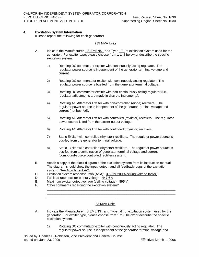
4. Excitation System Information (Please repeat the following for each generator)
285 MVA Units A. Indicate the Manufacturer SIEMENS and Type 7 of excitation system used for the
generator. For exciter type, please choose from 1 to 8 below or describe the specific excitation system.
1) Rotating DC commutator exciter with continuously acting regulator. The
regulator power source is independent of the generator terminal voltage and current.
2) Rotating DC commentator exciter with continuously acting regulator. The
regulator power source is bus fed from the generator terminal voltage. 3) Rotating DC commutator exciter with non-continuously acting regulator (i.e.,
regulator adjustments are made in discrete increments). 4) Rotating AC Alternator Exciter with non-controlled (diode) rectifiers. The
regulator power source is independent of the generator terminal voltage and current (not bus-fed).
5) Rotating AC Alternator Exciter with controlled (thyristor) rectifiers. The regulator
power source is fed from the exciter output voltage. 6) Rotating AC Alternator Exciter with controlled (thyristor) rectifiers.
7) Static Exciter with controlled (thyristor) rectifiers. The regulator power source is
bus-fed from the generator terminal voltage. 8) Static Exciter with controlled (thyristor) rectifiers. The regulator power source is
bus-fed from a combination of generator terminal voltage and current (compound-source controlled rectifiers system.
B. Attach a copy of the block diagram of the excitation system from its instruction manual.
The diagram should show the input, output, and all feedback loops of the excitation system. See Attachment A-2.
C. Excitation system response ratio (ASA): 3.5 (for 200% ceiling voltage factor) D. Full load rated exciter output voltage: 447.6 V E. Maximum exciter output voltage (ceiling voltage): 895 V F. Other comments regarding the excitation system?
____________________________________________________________________________________________________________________________________________________________________________________
83 MVA Units A. Indicate the Manufacturer SIEMENS and Type 4 of excitation system used for the
generator. For exciter type, please choose from 1 to 8 below or describe the specific excitation system. 1) Rotating DC commutator exciter with continuously acting regulator. The
regulator power source is independent of the generator terminal voltage and

CALIFORNIA INDEPENDENT SYSTEM OPERATOR CORPORATION FERC ELECTRIC TARIFF First Revised Sheet No. 1030 THIRD REPLACEMENT VOLUME NO. II Superseding Original Sheet No. 1030
Issued by: Charles F. Robinson, Vice President and General Counsel Issued on: June 23, 2006 Effective: March 1, 2006
current. 2) Rotating DC commentator exciter with continuously acting regulator. The
regulator power source is bus fed from the generator terminal voltage. 3) Rotating DC commutator exciter with non-continuously acting regulator (i.e.,
regulator adjustments are made in discrete increments). 4) Rotating AC Alternator Exciter with non-controlled (diode) rectifiers. The
regulator power source is independent of the generator terminal voltage and current (not bus-fed).
5) Rotating AC Alternator Exciter with controlled (thyristor) rectifiers. The regulator
power source is fed from the exciter output voltage. 6) Rotating AC Alternator Exciter with controlled (thyristor) rectifiers.
7) Static Exciter with controlled (thyristor) rectifiers. The regulator power source is
bus-fed from the generator terminal voltage. 8) Static Exciter with controlled (thyristor) rectifiers. The regulator power source is
bus-fed from a combination of generator terminal voltage and current (compound-source controlled rectifiers system.
B. Attach a copy of the block diagram of the excitation system from its instruction manual.
The diagram should show the input, output, and all feedback loops of the excitation system. See Attachment A-2.
C. Excitation system response ratio (ASA): 1.24 D. Full load rated exciter output voltage: 163 V E. Maximum exciter output voltage (ceiling voltage): 228 V F. Other comments regarding the excitation system?
____________________________________________________________________________________________________________________________________________________________________________________

CALIFORNIA INDEPENDENT SYSTEM OPERATOR CORPORATION FERC ELECTRIC TARIFF First Revised Sheet No. 1034 THIRD REPLACEMENT VOLUME NO. II Superseding Original Sheet No. 1034
Issued by: Charles F. Robinson, Vice President and General Counsel Issued on: June 23, 2006 Effective: March 1, 2006
5. Power System Stabilizer Information. (Please repeat the following for each generator. All new generators are required to install PSS unless an exemption has been obtained from WECC. Such an exemption can be obtained for units that do not have suitable excitation systems.)
285 MVA Units A. Manufacturer: Siemens B. Is the PSS digital or analog? Digital C. Note the input signal source for the PSS?
X Bus frequency _____ Shaft speed _____ Bus Voltage X – Generator Electrical Power Other (specify source)
D. Please attach a copy of a block diagram of the PSS from the PSS Instruction Manual and the correspondence between dial settings and the time constants or PSS gain. See Attachment A-2.
E: Other comments regarding the PSS? ____________________________________________________________ ____________________________________________________________ ____________________________________________________________
83 MVA Units
A. Manufacturer: Siemens B. Is the PSS digital or analog? Digital C. Note the input signal source for the PSS?
X Bus frequency _____ Shaft speed _____ Bus Voltage X – Generator Electrical Power Other (specify source)
D. Please attach a copy of a block diagram of the PSS from the PSS Instruction Manual and the correspondence between dial settings and the time constants or PSS gain. See Attachment A-2.
E: Other comments regarding the PSS? ____________________________________________________________ ____________________________________________________________ ____________________________________________________________
6. Turbine-Governor Information (Please repeat the following for each generator)
Please complete Part A for steam, gas or combined-cycle turbines, Part B for hydro turbines, and Part C for both.
285 MVA Units A. Steam, gas or combined-cycle turbines:
1.) List type of unit (Steam, Gas, or Combined-cycle): Gas 2.) If steam or combined-cycle, does the turbine system have a reheat process (i.e.,
both high and low pressure turbines)? N/A 3.) If steam with reheat process, or if combined-cycle, indicate in the space
provided, the percent of full load power produced by each turbine: Low pressure turbine or gas turbine: N/A% High pressure turbine or steam turbine: N/A%
B. Hydro turbines:

CALIFORNIA INDEPENDENT SYSTEM OPERATOR CORPORATION FERC ELECTRIC TARIFF First Revised Sheet No. 1034 THIRD REPLACEMENT VOLUME NO. II Superseding Original Sheet No. 1034
Issued by: Charles F. Robinson, Vice President and General Counsel Issued on: June 23, 2006 Effective: March 1, 2006
1.) Turbine efficiency at rated load: _______% 2.) Length of penstock: ______ft 3.) Average cross-sectional area of the penstock: _______ft2 4.) Typical maximum head (vertical distance from the bottom of the penstock, at the
gate, to the water level): ______ft 5.) Is the water supply run-of-the-river or reservoir: ___________ 6.) Water flow rate at the typical maximum head: _________ft3/sec 7.) Average energy rate: _________kW-hrs/acre-ft 8.) Estimated yearly energy production: ________kW-hrs
C. Complete this section for each machine, independent of the turbine type. 1.) Turbine manufacturer: Siemens 2.) Maximum turbine power output: 231 MW 3.) Minimum turbine power output (while on line): 120 MW 4.) Governor information: a: Droop setting (speed regulation): 4% b: Is the governor mechanical-hydraulic or electro-hydraulic
(Electro-hydraulic governors have an electronic speed sensor and transducer.)? Electro-hydraulic
c: Other comments regarding the turbine governor system? ______________________________________________ ______________________________________________ ______________________________________________ ______________________________________________
83 MVA Units
A. Steam, gas or combined-cycle turbines:
1.) List type of unit (Steam, Gas, or Combined-cycle): Steam 2.) If steam or combined-cycle, does the turbine system have a reheat process (i.e.,
both high and low pressure turbines)? No 3.) If steam with reheat process, or if combined-cycle, indicate in the space
provided, the percent of full load power produced by each turbine: Low pressure turbine or gas turbine: 47% High pressure turbine or steam turbine: 53%
B. Hydro turbines:
1.) Turbine efficiency at rated load: _______% 2.) Length of penstock: ______ft 3.) Average cross-sectional area of the penstock: _______ft2 4.) Typical maximum head (vertical distance from the bottom of the penstock, at the
gate, to the water level): ______ft 5.) Is the water supply run-of-the-river or reservoir: ___________ 6.) Water flow rate at the typical maximum head: _________ft3/sec 7.) Average energy rate: _________kW-hrs/acre-ft 8.) Estimated yearly energy production: ________kW-hrs
C. Complete this section for each machine, independent of the turbine type. 1.) Turbine manufacturer: Siemens 2.) Maximum turbine power output: 68 MW 3.) Minimum turbine power output (while on line): 10 MW

CALIFORNIA INDEPENDENT SYSTEM OPERATOR CORPORATION FERC ELECTRIC TARIFF First Revised Sheet No. 1034 THIRD REPLACEMENT VOLUME NO. II Superseding Original Sheet No. 1034
Issued by: Charles F. Robinson, Vice President and General Counsel Issued on: June 23, 2006 Effective: March 1, 2006
4.) Governor information: a: Droop setting (speed regulation): 5% b: Is the governor mechanical-hydraulic or electro-hydraulic
(Electro-hydraulic governors have an electronic speed sensor and transducer.)? Electro-hydraulic
c: Other comments regarding the turbine governor system? ______________________________________________ ______________________________________________ ______________________________________________ ______________________________________________
7. Synchronous Generator and Associated Equipment – Dynamic Models:
For each generator, governor, exciter and power system stabilizer, select the appropriate dynamic model from the General Electric PSLF Program Manual and provide the required input data. The manual is available on the GE website at www.gepower.com. Select the following links within the website: 1) Our Businesses, 2) GE Power Systems, 3) Energy Consulting, 4) GE PSLF Software, 5) GE PSLF User’s Manual. There are links within the GE PSLF User’s Manual to detailed descriptions of specific models, a definition of each parameter, a list of the output channels, explanatory notes, and a control system block diagram. The block diagrams are also available on the Ca-ISO website. If you require assistance in developing the models, we suggest you contact General Electric. Accurate models are important to obtain accurate study results. Costs associated with any changes in facility requirements that are due to differences between model data provided by the generation developer and the actual generator test data, may be the responsibility of the generation developer. See Attachment A-3.
8. Induction Generator Data:
A. Rated Generator Power Factor at rated load: ____________ B. Moment of Inertia (including prime mover): ____________ C. Do you wish reclose blocking? Yes ___, No ___
Note: Sufficient capacitance may be on the line now, or in the future, and the generator may self-excite unexpectedly.
9. Generator Short Circuit Data
For each generator, provide the following reactances expressed in p.u. on the generator base:
285 MVA Units • X”1 – positive sequence subtransient reactance: 0.1931 • X”2 – negative sequence subtransient reactance: 0.1931 • X”0 – zero sequence subtransient reactance: 0.1162
Generator Grounding:
A. _____ Solidly grounded B. X Grounded through an impedance

CALIFORNIA INDEPENDENT SYSTEM OPERATOR CORPORATION FERC ELECTRIC TARIFF First Revised Sheet No. 1034 THIRD REPLACEMENT VOLUME NO. II Superseding Original Sheet No. 1034
Issued by: Charles F. Robinson, Vice President and General Counsel Issued on: June 23, 2006 Effective: March 1, 2006
Impedance value in p.u on generator base. R: TBD p.u. X: 0 p.u. C. _____ Ungrounded
83 MVA Units • X”1 – positive sequence subtransient reactance: 0.156 • X”2 – negative sequence subtransient reactance: 0.156 • X”0 – zero sequence subtransient reactance: 0.098
Generator Grounding:
A. _____ Solidly grounded B. X Grounded through an impedance
Impedance value in p.u on generator base. R: TBD p.u. X: 0 p.u. C. _____ Ungrounded
10. Step-Up Transformer Data
For each step-up transformer, fill out the data form provided in Table 1. 11. Line Data
There is no need to provide data for new lines that are to be planned by the Participating TO. However, for transmission lines that are to be planned by the generation developer, please provide the following information: Nominal Voltage: 230 kV Line Length (miles): 0.572 miles (each circuit)
Line termination Points: Power Plant 230 kV bus and Pittsburg “D” 230 kV Bus Conductor Type: ACSR Size: 1590 kcmil (Falcon) If bundled. Number per phase: N/A, Bundle spacing: N/A in. Phase Configuration. Vertical: X , Horizontal: _______ Phase Spacing (ft): A-B: 17 feet, B-C: 17 feet, C-A: 34 feet Distance of lowest conductor to Ground: 49 ft Ground Wire Type: EHS Size: 0.5 inch dia. Distance to Ground: 100 ft Attach Tower Configuration Diagram Summer line ratings in amperes (normal and emergency) 1354 A Normal; 1547 A Emergency Resistance ( R ): 0.000075 p.u** Reactance: ( X ): 0.000789 p.u** Line Charging (B/2): 0.001758 p.u** ** On 100-MVA and nominal line voltage (kV) Base See Attachment A-4 for a tower configuration drawing.

CALIFORNIA INDEPENDENT SYSTEM OPERATOR CORPORATION FERC ELECTRIC TARIFF First Revised Sheet No. 1034 THIRD REPLACEMENT VOLUME NO. II Superseding Original Sheet No. 1034
Issued by: Charles F. Robinson, Vice President and General Counsel Issued on: June 23, 2006 Effective: March 1, 2006
12. Wind Generators
Number of generators to be interconnected pursuant to this Interconnection Request: ____ Elevation: ______ _____ Single Phase _____ Three Phase Inverter manufacturer, model name, number, and version: __________________________________________________________________ List of adjustable setpoints for the protective equipment or software: __________________________________________________________________ Field Volts: _________________ Field Amperes: ______________ Motoring Power (kW): _______ Neutral Grounding Resistor (If Applicable): ____________ I22t or K (Heating Time Constant): ____________ Rotor Resistance: ____________ Stator Resistance: ____________ Stator Reactance: ____________ Rotor Reactance: ____________ Magnetizing Reactance: ___________ Short Circuit Reactance: ___________ Exciting Current: ________________ Temperature Rise: ________________ Frame Size: _______________ Design Letter: _____________ Reactive Power Required In Vars (No Load): ________ Reactive Power Required In Vars (Full Load): ________ Total Rotating Inertia, H: ________ Per Unit on KVA Base Note: A completed General Electric Company Power Systems Load Flow (PSLF) data sheet must be supplied with the Interconnection Request. If other data sheets are more appropriate to the proposed device then they shall be provided and discussed at Scoping Meeting.

CALIFORNIA INDEPENDENT SYSTEM OPERATOR CORPORATION FERC ELECTRIC TARIFF First Revised Sheet No. 1035 THIRD REPLACEMENT VOLUME NO. II Superseding Original Sheet No. 1035
Issued by: Charles F. Robinson, Vice President and General Counsel Issued on: June 23, 2006 Effective: March 1, 2006
TABLE 1-1
TRANSFORMER DATA
UNIT 285 MVA Units
NUMBER OF TRANSFORMERS 1 per unit PHASE 3 Phase
RATED KVA H Winding X Winding Y Winding Connection
(Delta, Wye, Gnd.)
55 C Rise 65 C Rise
RATED VOLTAGE (kV) BIL (kV) AVAILABLE TAPS (planned or existing) LOAD TAP CHANGER? TAP SETTINGS
Grounded-Wye
__________
280 MVA
230
750
+/- 5% (2.5% each step)
No
1.0
Delta
__________
280 MVA
16.5
150
None
No
1.0
N/A
__________
N/A
N/A
N/A
N/A
N/A
__________ COOLING TYPE : OA_____ OA/FA_____ OA/FA/FA X OA/FOA______ IMPEDANCE H-X H-Y X-Y Percent MVA Base Tested Taps WINDING RESISTANCE Ohms
9%
168
1.0
H
TBD (0.5 – 1.0
Ohm)
N/A
N/A
N/A
X
TBD (0.005 – 0.010 Ohm)
N/A
N/A
N/A
Y
N/A
CURRENT TRANSFORMER RATIOS H 1200:5 X 12000:5 Y N/A N N/A
PERCENT EXCITING CURRENT 100 % Voltage: TBD 110% Voltage: TBD
Supply copy of nameplate and manufacture’s test report when available.

CALIFORNIA INDEPENDENT SYSTEM OPERATOR CORPORATION FERC ELECTRIC TARIFF First Revised Sheet No. 1035 THIRD REPLACEMENT VOLUME NO. II Superseding Original Sheet No. 1035
Issued by: Charles F. Robinson, Vice President and General Counsel Issued on: June 23, 2006 Effective: March 1, 2006
TABLE 1-2
TRANSFORMER DATA
UNIT 83 MVA Units
NUMBER OF TRANSFORMERS 1 per unit PHASE 3 Phase
RATED KVA H Winding X Winding Y Winding Connection
(Delta, Wye, Gnd.)
55 C Rise 65 C Rise
RATED VOLTAGE (kV) BIL (kV) AVAILABLE TAPS (planned or existing) LOAD TAP CHANGER? TAP SETTINGS
Grounded-Wye
__________
90 MVA
230
750
+/- 5% (2.5% each step)
No
1.0
Delta
__________
90 MVA
13.8
150
None
No
1.0
N/A
__________
N/A
N/A
N/A
N/A
N/A
__________ COOLING TYPE : OA_____ OA/FA_____ OA/FA/FA X OA/FOA______ IMPEDANCE H-X H-Y X-Y Percent MVA Base Tested Taps WINDING RESISTANCE Ohms
9%
54
1.0
H
TBD (0.5 – 1.0
Ohm)
N/A
N/A
N/A
X
TBD (0.005 – 0.010 Ohm)
N/A
N/A
N/A
Y
N/A
CURRENT TRANSFORMER RATIOS H 300:5 X 4000:5 Y N/A N N/A
PERCENT EXCITING CURRENT 100 % Voltage: TBD 110% Voltage: TBD
Supply copy of nameplate and manufacture’s test report when available.

Attachment A-1


Attachment A-2


Siemens Power Generation, Inc.
GENERATOR STABILITY MODEL DATA AT RATED MVA & kV Customer: SGT6-5000F(4) Turbine Unit(s): REFERENCE SGen6-1000A
Copyright 2006 Siemens Power Generation. All Rights Reserved. This document contains information confidential and proprietary to Siemens Power Generation. It is submitted in confidence and is to be used solely for the purpose for which it is furnished and returned upon request. This document and such information is not to be reproduced, transmitted, disclosed or used in whole or in part without the written authorization of Siemens Power Generation. Confidential.
Ratings: MVA: 285 kV: 16.5 Frequency (Hz): 60 SCR: 0.45
RPM: 3600 pf: 0.85 PSIG: N/A Type: AIR-Cooled
Reactances [per unit] Saturated Unsaturated Time Constants [s]
Direct axis Direct axis • Synchronous (Xd) 2.1215 2.3635 • Transient, open circuit. (T'do) 10.480• Transient (X'd) 0.2640 0.3001 • Sub-transient, open circuit. (T''do) 0.048 • Sub-transient (X''d) 0.1944 0.2255 • Transient, L-N short-circuit. (T'd1) 2.248
Quadrature axis • Sub-transient, L-N short-circuit (T''d1) 0.042
• Synchronous (Xq) 2.0665 2.3022 • Transient, L-L short-circuit (T'd2) 1.874
• Transient (X'q) 0.4323 0.4913 • Sub transient, L-L short-circuit (T''d2) 0.040
• Sub-transient (X''q) 0.1917 0.2225 • Transient, 3-phase short-circuit (T'd3) 1.171
Armature leakage, steady- state
(Xl) 0.1820 0.1916 • Sub transient, 3-phase short-circuit
(T''d3) 0.035
Zero sequence (X0) 0.1162 0.1224 Quadrature axis Negative sequence (X2) 0.1931 0.2240 • Transient, open-circuit. (T'qo) 1.164 Potier Reactance (XP) ---- 0.2555 • Sub-transient, open-circuit. (T''qo) 0.079 • Transient, L-N, short-circuit (T'q1) 0.331 Resistance and Capacitance • Sub-transient, L-N, short-circuit (T''q1) 0.053 Armature • Transient, L-L, short-circuit (T'q2) 0.292 • Zero Seq. Res. [p.u.] (R0) 0.00145 • Sub-transient, L-L short-circuit (T''q2) 0.049 • Positive Seq. Res. [p.u.] (R1) 0.00216 • Transient, 3-phase short-circuit (T'q3) 0.219 • Negative Seq. Res. [p.u.] (R2) 0.02039 • Sub-transient, 3 phase
short-circuit (T''q3) 0.035
• DC Res., per phase @ 75°C [Ω]
(Ra) 0.00072
• Capacitance to ground [µF/phase] 0.427 DC component of SC current (TA3) 0.685 Field DC component of L-N fault (TA1) 0.594
• DC Res. @ 75°C [Ω] (RF) 0.163 DC component of L-L fault (TA2) 0.685
Excitation/Field Data
Inertia Constants
Generator field voltage [V] 318.1 Turbine, Generator and Exciter, WR2 [lbf⋅ft2] 496446Exciter power [kW] Field current at rated pf [A]
640.01710
Turbine, Generator and Exciter, H Constant [kW-sec/kVA]
5.22
Field current required to put flux across air gap [A]
498 Short-circuit Torque Data
Exciter voltage [V] 350 Tsc = (MVA)[-pf+(Ae-atsin(ωt)-Be-btsin(2ωt)+Ce-ct)] Field current, no load. [A] 554 T1=A=6.798 α=a=3.012 Saturation factor at 1.0 x (rated kV) [%] 11.4 T2=B=3.399 β=b=3.103 Saturation factor at 1.2 x (rated kV) [%] 48.9 T3=C=0.593 γ=c=2.715
Engineer Date
Document Number____________________ Rev.__________

CUSTOMER: SGT6-5000F(4) GT UNIT: REFERENCE SGen6-1000A MISCELLANEOUS CURVES
2

CUSTOMER: SGT6-5000F(4) GT UNIT: REFERENCE SGen6-1000A MISCELLANEOUS CURVES
3

CUSTOMER: SGT6-5000F(4) GT UNIT: REFERENCE SGen6-1000A MISCELLANEOUS CURVES
4

CUSTOMER: SGT6-5000F(4) GT UNIT: REFERENCE SGen6-1000A EFFICIENCY
5
Efficiency is defined for the Generator (EFF), the Generator and Exciter (EFFE) and for the Generator, Exciter and Bearings (EFFEB).
Generator efficiency, excluding exciter and bearings. EFF 98.91%
Generator efficiency, including excitation losses. EFFE 98.89%
Generator efficiency, including excitation and bearing losses. EFFEB 98.75%

!"!#"
$%& "'!!(!)"(*
+
,-
. /!0!! -1 . !0)#
2. '*0)! 31 . "! 4 5,% &
. (06* 3 . *"!! % #!7'*
8 &, , 0,, !
, 9% $9 '
8 , 8, , (
19 1 5 *
2,9 :
5 "
-
; <= ! " #$%& '('( !

!" #$%$&'$&(
!"#! $" $"
% &' () *+) ,+)
-. / 0*) ) )
'! 1' ), ), ),
'! 2 3 4 5 ) ) ) ) ) )
.. 1 6)*6* 0)+ )+*
$7.8 - 9: - + + + + + +
%$ 4 ), ), ),
; # ' (* ( (* ( (* (
<7. 0"04 # ' 0 0 + 6 66 ,0
"04 "0 #"0 ' 6 ,0 +, 60+ 0,0 66
! 1= 6* 0 6
% - " > 6+) ()* 6+) ) 6+) 0+)
.4 4-?-1@ 1
4 >4-?. @ 1 0) ) 0)*
'! >664-?. @ 1 +) ,)0 ()(
.< 4 % () *&
< ;A . 5 5 ,)0 0)* 6)6 6)0 66)( ,)0
;B . 5 5 6+) 6) ), 6)6 6)6 6*)
.2.) ; . 5 5 6( * 6,0 6+( 6+ 60
+,$%- ;BB7 . 5 5 6)6 +)0 6()( 66) 6) 6)6
+04 ;B7 . 5 5 0+) 0)+ +6) +) () )(
;7 . 5 5 *( +( 6( 66* 60 6(
;6 . 5 5 *) )+ 6+) 6)0 6)* *)
; . 5 *), )0 6)
;1 . 5 0)( 6)6 ,)6
BB )6* )6* )6*
*/ B )(6 )(6 )(6
%! B +), +), +),
-. BB )06 )06 )06
)60 )60 )60
< %!"- Ω )6 )6 )6
6/ <%! Ω *)+ *)+ *)+
'! $C$ 5 ,) 0+) 0)
!. $C) 5 6) 0) ()0
&;.D .. 5 , , ,
66E
% #; &2 )6 )6 )6
$C F2; &2 0)( (+) +,)
=!- ?< @ > / +6 * + ,
=!- <?2!@ > / + 6 ,
! 1= ,6 ,6 ,6
=! 1= (0 (0 (0
1= +0 +0 +0
. 1= +0 0,
<6< 1= * 6+ 666
1= (* 00*
% 0"04 5 .'&& *,)6 *,)6+
D.; "04 5 *,)0 *,)6 *,),
$ 6"04 5 *() *()* *(),6
?D!@ "04 5 *)+ *+)+( *+)(
#/# 9 <20
012$3 < 6<26+6 6G 6(4(46+
$"

! " # $% $&
' (
" )* + ,* + %* +
- #&*% .+ #&*% .+ #&*% .+
/ $*,$, . 0*# . &*#, .
1 23 23 23
4 *% *% *%
0,* 5 #* 5 &* 5
"/"
678 1
0,00
0,80 0,85 0,90
0,95
0,975
1,00
0,975
0,95
0,90
0,85
0,80
0,700,600,400,20
Underexcited
Overexcited
0,700,600,400,200,00-0,6
-0,5
-0,4
-0,3
-0,2
-0,1
0,0
0,1
0,2
0,3
0,4
0,5
0,6
0,7
0,8
0,9
1,0
1,1
1,2
1,3
0,0
0,1
0,2
0,3
0,4
0,5
0,6
0,7
0,8
0,9
1,0
1,1
1,2
1,3
1,4
9"
:9"

!"# $%&%'
( )* + ,( *& -$*.( *' /
0( $'*& 1+ ( * $ -$*%.( '%* /
2( %*3%3 1 24( ')3
4( 56 24( $'7
2
8-.4
*%
*7
*
*&
$
$*%
$*7
*$ *% *' *7 * * *) *& *3 $
2,91:
0;0
*%
*7
*
*&
$
$*%
$*7
$*
$*&
%
2;2
!"""!""

!"# $%&'&(
$) *+ ,) +' -.) (*/
0) %(+' 1 .) 23 -.) %(4
-) &+/&/ 1 ) 4/+ 5
.""6
$-$
678.
practical stability limit (rotor angle safety margin at
80 degrees)
1.00
0.00
-0.00
rated
-rated
1/4
2/4
3/4
4/4
heating limit of stator and rotor winding
+
+%
+&
+(
+4
+
+
+*
+'
+/
%+
%+%
+
+%
+&
+(
+4
+
+
+*
+'
+/
%+
%+%
-9-
- ,9-,

!"#$ %&'(')
%* +, - .* ,( * /0, 1
* &),( 2- 3* 45
6* ',0'0 2 * ) #
%6%
7!893!!
i2²*t=
10sec.
0,08*i2continuous
34
68100
23
46
8101
23
46
8102
23
46
8103
2
101 8 6 4 2
100 8 6 4 333 2
10-1 8 6 4 3
:!;!'<#==>
!!<>

Compact Unit for Gas Turbine Sets
Description 02.2007
Static Excitation Equipment with Starting Frequency Converter 6RV...
G3
To line supply
Order no.: A5E00493996B AC

Transmission as well as duplication of this document, use and
communication of its content is not permitted unless expressly authorized.
Violation of this rule can lead to claims for damage compensation. All
rights reserved, especially for granting patents or for GM registration.
Exclusion of liability We have checked that the content of this document corresponds with the
hardware and software described. Nonetheless, differences cannot be
ruled out and we cannot, therefore, guarantee that they are completely
identical. The information contained in this documentation, however, is
checked regularly for errors. Any corrections needing to be made to the
text appear in later editions. Suggestions for improvement are welcome. © Siemens AG, 2007. All rights reserved
Subject to change without prior notice
Order No.: A5E00493996B AC Orders should be directed to A&D LD I Printed in the Federal Republic of Germany

Edition 02.2007
Siemens AG A5E00493996B AC Compact Unit for Gas Turbine Sets Description 3
Safety information This manual contains information that must be observed to ensure your personal safety and to prevent property damage. Notices referring to your personal safety are highlighted in the manual by a safety alert symbol; notices referring to property damage only have no safety alert symbol, these notices are highlighted by the following symbols depending on the relevant level of risk:
Danger
indicates the immediate risk of death, severe injury or significant damage to property if proper precautions are not taken.
Warning
indicates the potential risk of severe physical injury or even death if proper precautions are not taken.
Caution
(with a safety alert symbol) indicates the risk of slight physical injury if proper precautions are not taken.
Caution
(without a safety alert symbol) indicates the potential risk of property damage if proper precautions are not taken.
Notice
indicates the possibility of an undesirable result or condition if the corresponding information is not observed.
Qualified personnel
For the purpose of these operating instructions and the product warning labels, “qualified personnel” are those who are familiar with the installation, mounting, startup, operation, and maintenance of the product. They must have the following qualifications:
• Trained or authorized to energize, de-energize, ground, and tag circuits and equipment in accordance with established safety procedures.
• Trained in the proper care and use of protective equipment in accordance with established safety procedures.
• First aid training.

Edition 02.2007
Siemens AG A5E00493996B AC 4 Compact Unit for Gas Turbine Sets Description
Use as prescribed
Please note the following:
Warning
When electrical equipment is in operation, certain parts of this equipment are inevitably under dangerous voltage.
Incorrect handling of this equipment, i.e., failure to observe warning information can, therefore, lead to death, severe bodily injury or significant damage to property.
Only qualified personnel should work on or around the equipment.
These personnel must be thoroughly familiar with all warnings and maintenance procedures described in these operating instructions.
Professional transport, storage, mounting, and installation, as well as careful operation and service, are essential for the error-free, safe and reliable operation of the equipment.
Observance of national safety guidelines is mandatory.

Edition 02.2007
Siemens AG A5E00493996B AC Compact Unit for Gas Turbine Sets Description 5
ESD-sensitive components
Caution
The electronic modules contain components susceptible to electrostatic discharge. These components can be easily destroyed if not handled properly. If you have to work with electronic modules, please note:
• You should only touch electronic modules if absolutely necessary. • If you do have to touch modules, your body must be electrically discharged first. • Modules must not come into contact with highly insulating materials (such as plastic
parts, insulated desktops, articles of clothing manufactured from man-made fibers). • Modules must only be set down on conductive surfaces. • Modules and components should only be stored and transported in conductive
packaging (such as metalized plastic boxes or metal containers). • If the packaging material is not conductive, the modules must be wrapped with a
conductive packaging material (such as conductive foam rubber or household aluminum foil).
The necessary ESD protection measures are elucidated once again in the following illustration:
StandingSeated Seated/standinga
b
c
d
ac ca
f
e
d
e
d
f f
b
a = conductive floor surface d = ESD overall b = ESD table e = ESD wristband c = ESD shoes f = cabinet ground connection

Edition 02.2007
Siemens AG A5E00493996B AC 6 Compact Unit for Gas Turbine Sets Description
Contents Safety information........................................................................................................................3
ESD-sensitive components.........................................................................................................5
1 Description of the compact unit .................................................................................................9 1.1 Standard scope of supply ...............................................................................................9 1.2 Application ....................................................................................................................11 1.3 Features........................................................................................................................12 1.4 Overview and technical data of static excitation equipment (SEE) ..............................13 1.4.1 Single bridges without redundancy...............................................................................13 1.4.2 Bridges with redundancy ..............................................................................................14 1.4.3 Thyristor types for static excitation equipment .............................................................15 1.5 Overview and technical data of starting frequency converters (SFC) ..........................15 1.5.1 SFC thyristor types .......................................................................................................16 1.6 General technical data..................................................................................................16 1.7 Standards and regulations............................................................................................18 1.8 Dimension drawings of the starting frequency converter with static excitation
equipment .....................................................................................................................19 1.8.1 Starting frequency converter and static excitation equipment without
redundancy ...................................................................................................................19 1.8.2 Starting frequency converter and static excitation equipment with redundancy ..........20 1.9 Dimension drawings of individual static excitation units...............................................23 1.9.1 Static excitation equipment without/with redundancy (SITOR modules).....................23 1.9.2 Static excitation equipment without redundancy (stack design)..................................24 1.9.3 Static excitation equipment with redundancy (stack design)........................................25
2 Description of the static excitation equipment (SEE) ............................................................26 2.1 SEE power sections......................................................................................................26 2.1.1 Single bridges ...............................................................................................................28 2.1.2 Double bridges (two power sections) ...........................................................................28 2.1.3 Triple bridges (three power sections) ...........................................................................28 2.2 Open and closed-loop control.......................................................................................28 2.2.1 Versions........................................................................................................................30 2.2.1.1 Version 1.......................................................................................................................30 2.2.1.2 Version 2.......................................................................................................................31 2.2.1.3 Version 3.......................................................................................................................31 2.2.2 Starting mode (compact units only) ..............................................................................35 2.2.3 De-excitation.................................................................................................................35 2.2.4 Operator control and operating modes.........................................................................35 2.2.4.1 Local operator control on the control cabinet ...............................................................35 2.2.4.2 Operator control from the main control room................................................................38 2.3 The digital voltage controller.........................................................................................40 2.3.1 Actual-value sensing and conditioning .........................................................................41 2.3.2 Voltage control..............................................................................................................42 2.3.2.1 Reactive-power and power-factor control.....................................................................43 2.3.2.2 Power stabilization........................................................................................................43

Edition 02.2007
Siemens AG A5E00493996B AC Compact Unit for Gas Turbine Sets Description 7
2.3.3 Closed-loop current control.......................................................................................... 44 2.3.4 Limiting mechanisms ................................................................................................... 45 2.3.4.1 Stator-current limitation................................................................................................ 45 2.3.4.2 V/f limiting..................................................................................................................... 45 2.3.4.3 Underexcitation limiting................................................................................................ 46 2.3.4.4 Overexcitation limiting.................................................................................................. 47
3 Description of the starting frequency converter (SFC) ......................................................... 48 3.1 Operating modes ......................................................................................................... 48 3.2 Design .......................................................................................................................... 49 3.3 Open and closed-loop control ...................................................................................... 52
4 Description of the changeover device (option)...................................................................... 55

Edition 02.2007
Siemens AG A5E00493996B AC 8 Compact Unit for Gas Turbine Sets Description
Note
For clarity, these operating instructions do not contain every item of information in detail and, therefore, cannot consider every conceivable application.
If you need further information or encounter special problems that are not dealt with in sufficient detail in the operating instructions, please contact your local Siemens branch.
We would also like to point out that the content of these operating instructions is neither part of nor modifies any prior or existing agreement, commitment or contractual relationship. All obligations entered into by Siemens result from the respective contract of sale that contains the complete and sole valid warranty arrangements. These contractual guarantee provisions are neither broadened nor restricted by the text in these operating instructions.

Edition 02.2007
Siemens AG A5E00493996B AC Compact Unit for Gas Turbine Sets Description 9
1 Description of the compact unit
1.1 Standard scope of supply
The standard scope of supply of the compact unit consists of the following function units:
Static excitation equipment (SEE)
Power section: _ Line-side converter with 6 thyristors in three-phase bridge configuration with semiconductor fuses, up to 3 bridges in parallel
_ Line-side AC circuit breaker
_ DC-side overvoltage protection at DC output
_ Redundant fans (standard for single bridges)
Open-loop and closed-loop control section:
Hardware
_
Open-loop section: 2 SIMATIC S7 racks (for redundant open-loop control configuration)
_ Closed-loop section: 2 automatic channels (for redundant closed-loop control configuration), implemented in SIMOREG control modules with T400 technology module (can be switched over to manual operation)
_ Operator control and display panel (OP177B)
_ Power supply for open-loop control, signaling and monitoring
_ Interface modules, circuit breakers, socket
Software
_ Higher-level open-loop control, monitoring and communication to the 2nd automatic channel and the starting frequency converter
_ Redundant link between the PROFIBUS DP bus and instrumentation and control
_ Redundancy monitoring, channel changeover
_ Actual-value calculation, closed-loop limiting control
_ Gating unit
_ Closed-loop field current control If
_ Generator voltage control Ug

Edition 02.2007
Siemens AG A5E00493996B AC 10 Compact Unit for Gas Turbine Sets Description
Options
– Signal connection to the higher-level control stations via hardware terminals
– Closed-loop reactive power/power-factor control (standard)
– Power system stabilizer PSS
– Redundant three-phase bridges (2 x 100%, 3 x 50%)
– 12-pulse LSC for SFC with two three-phase bridges
– Changeover device for the starting frequency converter: Bus interface coupler and cable for bus interface, 3-pole outgoing isolator, monitoring and open-loop control
– Initial excitation
– Can be repaired while in operation, only with 2x100% three-phase bridge configuration with stack design and SITOR technology
– Activation of tapped transformer (unit transformer)
– Redundant fans for redundant power sections
Starting frequency converter (SFC)
Power section: _ Line-side converter LSC, 6-pulse or 12-pulse (standard for 9.0 MW converters) in a three-phase bridge configuration with direct connection to an SFC transformer
_ DC link reactor
_ Generator-side converter GSC, 6-pulse three-phase bridge configuration
_ Fuseless design for the line-side and generator-side converter (although the external starting disconnector features fuses, they are not part of the scope of supply of the starting frequency converter)
_ Line-side and generator-side overvoltage protection
Open-loop and closed-loop control section:
Hardware
_ 1 Control Unit (CU320) with interface modules
_ Power supply for open-loop control, signaling and monitoring
_ Interface modules, circuit breakers
Software
_ Converter-based open-loop and closed-loop speed control
_ Open-loop and closed-loop control of line-side and generator-side converters
_ Higher-level open-loop control, monitoring functions and communication to the static excitation equipment’s open-loop and closed-loop control (SIMATIC S7)

Edition 02.2007
Siemens AG A5E00493996B AC Compact Unit for Gas Turbine Sets Description 11
– MV transformer temperature monitoring PT100
– Anti-condensation heating with thermostat
– Cabinet lighting
– Additional cooling for ambient temperatures > 40°C to 45°C
– Attenuator for starting frequency converter (only necessary in the absence of a generator circuit breaker)
– Earthquake-proof cabinet design
1.2 Application
Compact units for gas turbine sets are power electronic devices comprising a static generator excitation unit (SEE) and a starting frequency converter (SFC) (current-source DC link converter).
The turbine requires assistance to accelerate the gas turbine set up to its operating speed, as it can only generate the torque required for continued acceleration once it has reached approx. 50% of its rated speed.
The generator is supplied with power from the starting frequency converter during this initial starting phase and is operated as a frequency-controlled synchronous motor. The converters shut down at approx. 70% of the rated speed; after this, the generator set is accelerated by the turbine alone.
It is possible to use a single starting frequency converter to accelerate a number of turbine sets one after the other.
For reasons of availability, a maximum of 6 gas turbine sets can be combined with 3 compact units and 3 individual static excitation units. By combining the switchgear appropriately, each of the turbine sets can be operated with each of the converters (refer to Chapter 4 "Description of the changeover device").
In terms of their dimensions, although the units have been designed specifically for compact installation and use in pre-fabricated containers, they are also suitable for use in conventional electrical switchgear rooms or machine halls, with upgraded cabinet degree of protection.
The compact units have been designed as a standard series and are optimized for operation with Siemens/PG gas turbine sets to ensure the required starting times and duty cycles (refer to the overviews in Sections 1.4 and 1.5).

Edition 02.2007
Siemens AG A5E00493996B AC 12 Compact Unit for Gas Turbine Sets Description
1.3 Features
• Compact units and individual static excitation units are factory-mounted, wired and checked in cabinets from the 8MF system. They are supplied as ready-to-use units. This significantly reduces startup time and costs at customer sites.
• Primary components such as power sections, DC-link smoothing reactor and subracks for open-loop and closed-loop control are installed in separate cabinets.
• Integrated radial fans dissipate heat; the fans are redundant for the static excitation equipment (single bridges only).
• Line stressing during starting remains low. The starting frequency converter does not influence the short-circuit rating of the station service (auxiliaries, etc.).
• The optional changeover device can be used to make it possible to start additional gas turbine sets using the same starting frequency converter. As part of this process, the control signals are transferred between the SFC and SEE open-loop control via a serial bus connection.
• The starting and static excitation equipment is able to exchange signals with the instrumentation and control for the purpose of operator control and monitoring as well as for error signaling.
• Digital SIMATIC S7 and SIMOREG CM (SEE) or SINAMICS (SFC) are used for all open-loop and closed-loop control tasks; these are 3 well-proven systems for fast open-loop and closed-loop control and arithmetic tasks in drive and power engineering with the following characteristics and features:
– Modular design and subdivision into clear, transparent function diagrams using the STEP 7 and CFC graphics-based configuration languages, with correspondingly transparent documentation
– Option to connect a PC or PG
– Suitable software packages are available to make parameter adaptation easy.
– Self-test routines
– Intelligent operator control and display unit for local control with plain-text messages and time stamp
– Trace memory for recording fast sequences for diagnostics and troubleshooting (complete fault history before and after the event), read out using option to connect PC or PG
• The medium-voltage converter for gating and monitoring the optocoupler and fiber-optic cable power semiconductors.
• Mechanical encoders are not required on the rotor for open-loop and closed-loop control and monitoring of the SFC. The information required is derived from the electrical generator stator actual values CT and VT (current and voltage).
• The generator-side converter can be optimally gated using voltage clocking of the starting frequency converter. Throughout the run-up phase the firing angle is kept close to the inverter stability limit, thereby permitting the converter output to be fully utilized.

Edition 02.2007
Siemens AG A5E00493996B AC Compact Unit for Gas Turbine Sets Description 13
• The turbine set is accelerated from the lowest speed range, where the generator is not yet able to provide sufficient commutating voltage, by means of DC-link pulsing of the SFC’s line-side converter.
• Where startup and fault-finding service and support are concerned, the compact unit provides a whole series of resources which can be ordered as optional extras, e.g., fault recorder and remote diagnostics.
1.4 Overview and technical data of static excitation equipment (SEE)
1.4.1 Single bridges without redundancy
Type SEE 780/1500 SEE 750/2400 SEE 550/2900 SEE 900/4500 SEE 900/6000
SITOR modules Stack design
Rated excitation current IE rated 1,365 A 2,182 A 2,636 A 4,090 A 5,455 A
Max. continuous current IE max (= 1.1 x IE rated)
1,500 A 2,400 A 2,900 A 4,500 A 6,000 A
Impulse test current Ip (10 s) 2,250 A 3,600 A 4,350 A 6,000 A 7,640 A
Ip/IE rated 1.65 1.65 1.65 1.40 1.40
Max. input voltage 780 V 750 V 550 V 900 V 900 V
Thyristor type T1219 N25 T2101 N25 T2551 N18 T3801 N36 T3801 N36
Voltage rating factor* 2.27 2.36 2.31 2.83 2.83
Redundancy 1 x 100% 1 x 100% 1 x 100% 1 x 100% 2 x 50%
Rated losses 7.5 kW 10 kW 11 kW 26 kW 35.5 kW
Required cooling air (2 fans) 3,200 m³/h 3,200 m³/h 3,200 m³/h 5,760 m³/h 11,520 m³/h
Sound pressure level 50 Hz power supply 60 Hz power supply
70 dB(A) 73 dB(A)
70 dB(A) 73 dB(A)
70 dB(A) 73 dB(A)
73 dB(A) 76 dB(A)
74 dB(A) 77 dB(A)
Weight 1,200 kg 1,300 kg 1,300 kg 1,660 kg 2,750 kg
Dimensions Refer to dimension drawings
*) based on rated input voltage

Edition 02.2007
Siemens AG A5E00493996B AC 14 Compact Unit for Gas Turbine Sets Description
1.4.2 Bridges with redundancy
Type SEE 780/1500R
SEE 750/2400R
SEE 550/2900R
SEE 900/4500R
SEE 900/6000R
SITOR modules Stack design
Rated excitation current IE rated 1,365 A 2,182 A 2,636 A 4,090 A 5,455 A
Max. continuous current IE max (= 1.1 x IE rated)
1,500 A 2,400 A 2,900 A 4,500 A 6,000 A
Impulse test current Ip (10 s) 2,250 A 3,600 A 4,350 A 6,000 A 7,640 A
Ip/IE rated 1.65 1.65 1.65 1.40 1.40
Max. input voltage 780 V 750 V 550 V 900 V 900 V
Thyristor type T1219 N25 T2101 N25 T2551 N18 T3801 N36 T3801 N36
Voltage rating factor* 2.27 2.36 2.31 2.83 2.83
Redundancy 2 x 100% 2 x 100% 2 x 100% 2 x 100% 3 x 50%
Rated losses 7.5 kW 10 kW 11 kW 30 kW 38 kW
Required cooling air (3 to 4 fans) 3,200 m³/h 3,200 m³/h 3,200 m³/h 11,520 m³/h 17,280 m³/h
Sound pressure level 50 Hz power supply 60 Hz power supply
70 dB(A) 73 dB(A)
70 dB(A) 73 dB(A)
70 dB(A) 73 dB(A)
85 dB(A) 87 dB(A)
87 dB(A) 89 dB(A)
Weight 1,740 kg 2,000 kg 2,000 kg 3,100 kg 5,000 kg
Dimensions Refer to dimension drawings
*) based on rated input voltage
The data is valid when using an excitation transformer with the following data:
– uk ≤ 6%
– Rated power corresponding to the relevant rated excitation current and selected input voltage ≤ rated voltage
Control data: – Control accuracy ≤ ±0.5%
– Control range 85 ... 110% Urated
– Setting range (manual) 0 ... 110% Irated
– Controller dead band ≤ ±0.1%
– Mean excitation response ≥ 3 s-¹ (dependent on surge factor)
– Surge factor ≥ 1.8 (dependent on input voltage in relation to rated field data)
– Initial excitation time ≤ 10 ms

Edition 02.2007
Siemens AG A5E00493996B AC Compact Unit for Gas Turbine Sets Description 15
1.4.3 Thyristor types for static excitation equipment
EUPEC or SIEMENS
T1219 N25 R66 L166
T2101 N25 T66 166
T2551 N18 T65 120
T3801 N36
Recurring peak off-state voltage 2,500 V 2,500 V 1,800 V 3,600 V
Max. continuous current λ = 180°el, sine Tc = 85°C, Eupec
1,050 A 2,100 A 2,550 A 3,810 A
Wafer size 2 ” 3 ” 3 ” 4 ”
1.5 Overview and technical data of starting frequency converters (SFC)
SFC Type
2.9 4.0 5.0 9.0
Device version Stack design
Rated power 3.7 MVA 5.1 MVA 6.25 MVA 2 x 5.7 MVA
Rated input voltage 1.4 kV 2.5 kV 2.5 kV 2 x 2.3 kV
DC-link power 2.9 MW 4.0 MW 5.0 MW 9.0 MW
DC-link current 1,850 A 1,430 A 1,770 A 1,750 A
DC-link voltage 1,560 V 2,800 V 2,800 V 5,140 V
Thyristor type LSC
Thyr. connected in series
Thyristor type GSC
Thyr. connected in series
T1551 N52
1
T1551 N52
1
T1851 N70
1
T1851 N70
1
T1851 N70
1
T1851 N70
1
T1851 N70
2 x 1
T1851 N70
2
Voltage rating factor 2.12 2.03 2.03 2.21
Rated losses 36 kW 45 kW 53 kW 76 kW
Required cooling air 7,200 m³/h 7,200 m³/h 7,200 m³/h 14,400 m³/h
Sound pressure level*) 50 Hz power supply 60 Hz power supply
83 dB(A) 85 dB(A)
83 dB(A) 85 dB(A)
83 dB(A) 85 dB(A)
88 dB(A)
Weight*) 2,400 kg 3,000 kg 3,300 kg 4,500 kg
Dimensions Refer to dimension drawings
DC-link reactor Rated current Starting current Inductance Insulating voltage
1,120 A 1,850 A 2.0 mH 2.5 kV
885 A
1,430 A 4.1 mH 4.0 kV
1,000 A 1,770 A 3.2 mH 5.0 kV
925 A
1,750 A 5.2 mH 8.0 kV
*) SFC power sections only with reactor but no static excitation equipment

Edition 02.2007
Siemens AG A5E00493996B AC 16 Compact Unit for Gas Turbine Sets Description
1.5.1 SFC thyristor types
EUPEC or SIEMENS
T1551 N52
T1851 N70
T2251 N80
Recurring peak off-state voltage 5,000 V 7,200 V 8,200 V
Max. continuous current Tc = 85°C, eupec 1,830 A 1,850 A 2,250 A
Wafer size 3.5 ” 3.5 ” 4 ”
The data is valid when using a converter transformer with the following data:
– uk > 12% referred to the starting frequency converter apparent power output
Duty cycle
Power dimensioning for the starting frequency converters is based on the following duty cycle:
– 4 starts, each 240 s under load with a no-load interval of 150 s, followed by a 2 hour no-load period
– Maximum ambient temperature 40°C
– Thermal monitoring of the duty cycle
Please ask about other duty cycles.
1.6 General technical data
Max. input voltage Tolerance
Refer to overview ±10%
Rated line frequency Tolerance
50 Hz or 60 Hz ±2%
EMC immunity In conformity with DIN VDE 0843, corresponding to IEC 801
Device version In conformity with DIN EN 60146 (VDE 0558), corresponding to IEC 146
According to DIN EN 50178 the unit must be designated as "conditionally short-circuit-proof".
Insulation Overvoltage category II, degree of pollution 2, insulating material class III, non-homogenous field in conformity with DIN EN 50178 (VDE 0160) using the tables acc. to DIN VDE 0110 (1/89), corresponding to IEC 664

Edition 02.2007
Siemens AG A5E00493996B AC Compact Unit for Gas Turbine Sets Description 17
Environmental conditions Application classes in conformity with DIN EN 60721, corresponding to IEC 721
Storage - 20°C +60°C ≤ 85% (1K2) no moisture condensation
Transport - 20°C +60°C ≤ 85% (2K2) light moisture condensation
Operation - 0°C +40°C ≤ 85% (3K3) no moisture condensation
Climatic conditions Lower limit temperature Upper limit temperature Relative air humidity
For ambient temperatures above 40°C the rated output or rated current should be derated by 10% per 5°C.
Mechanical conditions Storage Transport Operation
1M2 2M2 3M1
In acc. with IEC 60721-3-1 In acc. with IEC 60721-3-2 In acc. with IEC 60721-3-3
Site altitude Max. 1,000 m above sea level For altitudes exceeding 1,000 m above sea level the SFC DC-link power or SEE rated current IE rated should be reduced by 5% per 300 m. The voltage must be reduced at and above 2,000 m above sea level.
Degree of protection IP32 in conformity with DIN VDE 0470, Part 1, corresponding to IEC 60529
Cabinet paint finish Standard On request (option)
RAL 7035 Other RAL colors
Front panel SN 30920 - A615 - B14 (turquoise, Siemens standard)
Warning
The unit is not designed to be arc-resistant.
It is intended for installation in closed electrical operating areas. However, if the unit is installed in a freely accessible electrical operating area, the area around it must be clearly demarcated and appropriate warning notices displayed by its operator.
Non-observance of the warnings can results in serious injury to persons or damage to property.

Edition 02.2007
Siemens AG A5E00493996B AC 18 Compact Unit for Gas Turbine Sets Description
1.7 Standards and regulations
The following standards and regulations have been applied as relevant:
IEC 62103 (DIN EN 50178/VDE 0160)
Electronic equipment for use in power installations
IEC 60146--1--1 (DIN EN 60146--1--1/VDE 0558 Part 11; without revision of 08/01/2003)
Semiconductor converters - General requirements and line commutated converters – Part 1--1: Specifications of basic requirements
IEC 61800-3 (DIN EN 61800-3/VDE 0160 Part 100; covered by DIN EN 50178)
Adjustable speed electrical power drive systems – Part 3: EMC requirements and specific test methods
DIN EN 60204-1 of 11/01/1998 Equipment of machines *)
DIN EN 60204-11 of 05/01/2001 Equipment of machines > 1 kV
*) The converter complies with the Low-Voltage Directive and the Machinery Directive. It should be noted that the EMC Directive applies only to installations and not to products. The converter is designed to comply with European legislation.

Edition 02.2007
Siemens AG A5E00493996B AC Compact Unit for Gas Turbine Sets Description 19
1.8 Dimension drawings of the starting frequency converter with static excitation equipment
1.8.1 Starting frequency converter and static excitation equipment without redundancy
36
4
3900
22
00
33
3600 900 1200
UNIT 1 UNIT 2
100 600 600600600
Open-loop and closed-loop controlPower section SEE Power section SFC line side Power section SFC generator sideSmoothing reactor Surge arrester SFC DC overvoltage protection
Fig. 1.1 Compact unit SFC 2.9 MW with static excitation equipment (1x100% SITOR modules)

Edition 02.2007
Siemens AG A5E00493996B AC 20 Compact Unit for Gas Turbine Sets Description
1.8.2 Starting frequency converter and static excitation equipment with redundancy
4500
600 900 1200UNIT 1 UNIT 2
600 600 600 600 600
Open-loop and closed-loop controlPower section SEE Power section SFC line side Power section SFC generator sideSmoothing reactor Surge arrester SFC DC overvoltage protection
Fig. 1.2 Compact unit SFC 2.9 with static excitation equipment (2x100% SITOR modules)

Edition 02.2007
Siemens AG A5E00493996B AC Compact Unit for Gas Turbine Sets Description 21
Fig. 1.3 Compact unit SFC 4.0/5.0 with static excitation equipment (2x100% stack design)

Edition 02.2007
Siemens AG A5E00493996B AC 22 Compact Unit for Gas Turbine Sets Description
Fig. 1.4 Compact unit SFC 9.0 with static excitation equipment (3x50% stack design)

Edition 02.2007
Siemens AG A5E00493996B AC Compact Unit for Gas Turbine Sets Description 23
1.9 Dimension drawings of individual static excitation units
1.9.1 Static excitation equipment without/with redundancy (SITOR modules)
22
00
33
3
100
22
00
33
3
100
Fig. 1.5: Individual static excitation unit (SITOR module)

Edition 02.2007
Siemens AG A5E00493996B AC 24 Compact Unit for Gas Turbine Sets Description
1.9.2 Static excitation equipment without redundancy (stack design)
Fig. 1.6: Individual static excitation unit (stack design)

Edition 02.2007
Siemens AG A5E00493996B AC Compact Unit for Gas Turbine Sets Description 25
1.9.3 Static excitation equipment with redundancy (stack design)
Open-loop and closed-loop controlPower sections SEEDC overvoltage protectionAC incoming circuit breaker
SEE 900/4500 R (2 x 100%)
SEE 900/6000 R (3 x 50%)
30001200
600 600 900 900
5400
12001200900 900 900900600
Open-loop and closed-loop controlPower sections SEEDC overvoltage protection
Fig. 1.7: Individual static excitation unit (stack design)

Edition 02.2007
Siemens AG A5E00493996B AC 26 Compact Unit for Gas Turbine Sets Description
2 Description of the static excitation equipment (SEE)
The operating ranges and limit values specified in association with the static excitation equipment should be regarded as non-binding guide values. The limits and rated values of the static excitation equipment are adapted to the generator dimensions during commissioning.
2.1 SEE power sections
Auxiliary voltageFan power supply
Field winding
AC circuit breaker
Externalfiring
L-L+
U
U
U>Firing module
Overvoltage protectionDC-side
Firing pulse
q-axis currentsensing
Resistor unit
U
U
DC-voltageactual value,Channel 1
Open-loop andclosed-loop section
M
U
U
U
U
Alarm
DC-voltageactual value,Channel 2
L1 L2 L3
Fusemonitoring
Direct-currentactual value,Channel 1
Direct-currentactual value,Channel 2
SICROWBAR
Fig. 2.1 Circuit diagram of a static excitation unit's power section with 1 bridge (1x100%), SITOR modules or stack design; fuse monitoring identical for configuration with 2 bridges (2x100%)

Edition 02.2007
Siemens AG A5E00493996B AC Compact Unit for Gas Turbine Sets Description 27
Auxiliary voltageFan power supply
Field winding
AC circuit breaker
Externalfiring
L-L+
U
U
Overvoltage protectionDC-side
Firing pulse
Resistor unit
U
U
DC-voltageactual value,Channel 1
Open-loop andclosed-loop section
M
U
U
U
U
Alarm
DC-voltageactual value,Channel 2
L1 L2 L3
Direct-currentactual value,Channel 1
Direct-currentactual value,Channel 2
Current-flowmonitoring
U>Firing module
q-axis currentsensing
SICROWBAR
Fig. 2.2 Circuit diagram of a bridge for a static excitation unit's power section configured with 3 bridges (3x50%), stack design

Edition 02.2007
Siemens AG A5E00493996B AC 28 Compact Unit for Gas Turbine Sets Description
2.1.1 Single bridges
A static excitation unit's power section (Fig. 2.1 and 2.2) essentially comprises the following components:
– Line-side AC circuit breaker
– Fully-controlled three-phase bridge connection consisting of 6 force-cooled 6QA50 SITOR thyristor modules or 6 thyristors in a force-cooled stack design
– Thyristor branch fuses are monitored via fuse monitoring.
– Current and voltage sensing in the DC field circuit
– DC-side overvoltage protection for rotor and thyristors
The power section's power losses are dissipated using 2 redundant radial fans (can be switched over). The controller channels can be switched over to the single bridges, see Fig. 2.3.
2.1.2 Double bridges (two power sections)
In the event of a fault on a bridge, the faulty bridge can be switched over to the redundant bridge virtually bumplessly by shifting and enabling the corresponding gate trigger pulses. The ON-status of the redundant bridge is such that the pulses simply need to be enabled. The thyristor branch fuses are monitored via fuse monitoring.
The controller channels are permanently assigned to the bridges, see Fig. 2.4.
2.1.3 Triple bridges (three power sections)
During normal operation, all three bridges operate in parallel. In the event of a fault on a bridge, the affected bridge is switched off (the gate trigger pulses are disabled by disconnecting the power supply to the gate trigger pulse module). The remaining bridges take over the current. Unlike in the case of single and double bridges, where fuse monitoring is used, a conduction monitor monitors the current in the bridges and fuses connected in parallel, see Fig. 2.5.
2.2 Open and closed-loop control
The digital SIMATIC S7 control system and SIMOREG CMs with T400 are used for all open-loop and closed-loop control functions, see Fig. 2.3, 2.4 and 2.5.
The components for the static excitation equipment are combined in a single cabinet panel and essentially comprise:
In the front of the cabinet:
– 2 SIMATIC S7 racks (redundant open-loop and closed-loop control)
– 2 SIMOREG control modules with T400 (redundant open-loop and closed-loop control)
– Actual-value interposing current transformer (for Ug and Ig)

Edition 02.2007
Siemens AG A5E00493996B AC Compact Unit for Gas Turbine Sets Description 29
– Pulse switching relays and interface modules
In the rear of the cabinet:
– SINAMICS GL150 open-loop and closed-loop control
– Interface modules, terminals for the power supply and spring terminal modules, as well as customer terminal strips
– 24 V DC power supply and miniature circuit breakers
– Optional: DC/DC converter 220 V/24 V
In the cabinet doors (see Fig. 2.6):
– 1 operator control panel OP177B (Fig. 2.7)
– 1 key-operated switch for selecting "standard operation" and "local operation" modes
Optional:
– Pointer instruments, e.g., for generator voltage Ug, generator current Ig and frequency fg, as well as field voltage Uf and field current If
– 4 to 8 indicator lights

Edition 02.2007
Siemens AG A5E00493996B AC 30 Compact Unit for Gas Turbine Sets Description
2.2.1 Versions The open-loop and closed-loop control equipment is available in 3 versions, which are fundamentally different in terms of design and mode of operation.
• Version 1 – Non-redundant design (see Fig. 2.2.1.1) • Version 2 – Semi-redundant design (see Fig. 2.2.1.2) • Version 3 – Fully redundant design (see Fig. 2.2.1.3)
2.2.1.1 Version 1 Version 1 comprises 1 SIMATIC S7 rack and 1 SIMOREG control module with T400 (with 1 manual and 1 automatic channel); this version does not support redundancy. It has 2 Profibus DP links with instrumentation and control.
Fig. 2.2.1.1 Version 1 - Non-redundant design

Edition 02.2007
Siemens AG A5E00493996B AC Compact Unit for Gas Turbine Sets Description 31
2.2.1.2 Version 2 Version 2 comprises 1 SIMATIC S7 rack and 2 SIMOREG control modules with T400 (each with 1 manual and 1 automatic channel); this version supports redundancy on the closed-loop control side (SIMOREG CM). It has 2 Profibus DP links with instrumentation and control.
Fig. 2.2.1.2 Version 2 – Semi-redundant design
2.2.1.3 Version 3 Version 3 comprises 2 SIMATIC S7 racks and 2 SIMOREG control modules with T400 (each with 1 manual and 1 automatic channel); this version supports full redundancy, both on the open-loop (SIMATIC S7) and closed-loop (SIMOREG CM) control sides.
Fig. 2.2.1.3 Version 3 – Fully redundant design The 3 circuit diagrams below are mapped in Version 3 (with full redundancy).

Edition 02.2007
Siemens AG A5E00493996B AC 32 Compact Unit for Gas Turbine Sets Description
-A100 -A200
~
_
Open-loop control
Gating unit
Interfaces
Firing pulse
Channel 1
Channel 2
Actual valuesChannel 1
Actual valuesChannel 2
Power section
Station service rail, e.g., 6 kV
Operator panel
Three-phase bridge
Binary signalConditioning
ControllerAutomatic/
Manual
PulseChangeover
SIMATIC S7
SIMOREG CM
-A101
Open-loop control
SIMATIC S7
Gating unit
Interfaces
ControllerAutomatic/
Manual
SIMOREG CM
-A201IU
IU
I U I U
Instrumentation and control
e.g., T3000or
-A100 -A200
~
_
Open-loop control
Gating unit
Interfaces
Firing pulse
Channel 1
Channel 2
Operator panel
Three-phase bridge
Binary signalConditioning
ControllerAutomatic/
Manual
PulseChangeover
SIMATIC S7
SIMOREG CM
-A101
SIMATIC S7
Gating unit
Interfaces
ControllerAutomatic/
Manual
SIMOREG CM
-A201IU
U
I U I U
Instrumentation and control
e.g., T3000 via ProfibusGenerator voltage Ug
10.5 ... 21 kV
BUS
-A100 -A200
~
_
Open-loop control
Gating unit
Interfaces
Firing pulse
Open-loop and closed-loop
control
Gas turbine set with starting frequency converter
Actual valuesChannel 1
Actual valuesChannel 2
Rotorprotection
Open and closed-loop control
Synchronizing voltage
Operator panel
Three-phase bridge
AC circuit breaker (secondary side)
Binary signalConditioning
ControllerAutomatic/
Manual
PulseChangeover
SIMATIC S7
SIMOREG CM
-A101
Open-loop control
SIMATIC S7
Gating unit
Interfaces
ControllerAutomatic/
Manual
SIMOREG CM
-A201IU
U
I U I U
Profibus DP
Instrumentation and control
Optional HW interface
MV circuit breaker(primary side)
Fig. 2.3 Circuit diagram of open-loop and closed-loop control for the static excitation equipment with single
bridge

Edition 02.2007
Siemens AG A5E00493996B AC Compact Unit for Gas Turbine Sets Description 33
-A100 -A200
~
_
Open-loop control
Gating unit
Interfaces
Firing pulse
Channel 1
Channel 2
Station service rail, e.g., 6 kV
Operator panel
Binary signalConditioning
ControllerAutomatic/
Manual
SIMATIC S7
SIMOREG CM
-A101
Open-loop control
SIMATIC S7
Gating unit
Interfaces
ControllerAutomatic/
Manual
SIMOREG CM
-A201IU
IU
I U I U
Instrumentation and control
e.g., T3000or
-A100 -A200
~
_
Open-loop control
Gating unit
Interfaces
Channel 1
Channel 2
Station service rail, e.g., 6 kV
Operator panel
Instrumentation and control
Binary signalConditioning
ControllerAutomatic/
Manual
SIMATIC S7
SIMOREG CM
-A101
Open-loop control
SIMATIC S7
Gating unit
Interfaces
ControllerAutomatic/
Manual
SIMOREG CM
-A201
U
U
I U I U
Instrumentation and control
e.g., T3000 via ProfibusGenerator voltage Ug
10.5 ... 21 kV
BUS
-A100 -A200
~
_
Open-loop control
Gating unit
Interfaces
Open-loop and closed-loop
control
Gas turbine set with starting frequency converter
Actual valuesChannel 1
Actual valuesChannel 2
Power section
Open-loop and closed-loop control
Synchronizing voltage
Station service rail, e.g., 6 kV
MV circuit breaker(primary side)
Operator panel
Optional HW interface
Three-phase bridges
AC circuit breaker (secondary side)
Binary signalConditioning
ControllerAutomatic/
Manual
SIMATIC S7
SIMOREG CM
-A101
Open-loop control
SIMATIC S7
Gating unit
Interfaces
ControllerAutomatic/
Manual
SIMOREG CM
-A201
U
U
I U I U
Profibus DP
~
_
~
_
~
_
Rotorprotection
Fig. 2.4 Circuit diagram of open-loop and closed-loop control for the static excitation equipment with 2
"standby” bridges

Edition 02.2007
Siemens AG A5E00493996B AC 34 Compact Unit for Gas Turbine Sets Description
-A100 -A200
~
_
Open-loop control
Gating unit
Interfaces
Channel 1
Channel 2
Actual valuesChannel 1
Actual valuesChannel 2
Station service rail, e.g., 6 kV
Operator panel
Binary signalConditioning
ControllerAutomatic/
Manual
SIMATIC S7
SIMOREG CM
-A101
Open-loop control
SIMATIC S7
Gating unit
Interfaces
ControllerAutomatic/
Manual
SIMOREG CM
-A201IU
IU
I U I U
Instrumentation and control
e.g., T3000or
-A100 -A200
~
_
Gating unit
Interfaces
Channel 1
Channel 2
Station service rail, e.g., 6 kV
Operator panel
Binary signalConditioning
ControllerAutomatic/
Manual
SIMATIC S7
SIMOREG CM
-A101
SIMATIC S7
Gating unit
Interfaces
ControllerAutomatic/
Manual
SIMOREG CM
-A201
U
U
I U I U
Instrumentation and control
e.g., T3000 via Profibus
BUS
-A100 -A200
~
_
Open-loop control
Gating unit
Interfaces
Actual valuesChannel 1
Actual valuesChannel 2
Power section
Open and closed-loop control
Synchronizing voltage
Station service rail, e.g., 6 kV
Operator panel
Three-phase bridges
AC circuit breaker (secondary side)
Binary signalConditioning
ControllerAutomatic/
Manual
SIMATIC S7
SIMOREG CM
-A101
Open-loop control
SIMATIC S7
Gating unit
Interfaces
ControllerAutomatic/
Manual
SIMOREG CM
-A201
U
U
I U I U
Instrumentation and control
Profibus DP
~
_
~
_
~
_
~
_
~
_
~
_
Generator voltage Ug 10.5 ... 21 kV
Firing pulse
PulseChangeover
Firing pulse
PulseChangeover
Firing pulse
PulseChangeover
Instrumentation and control
Optional HW interface
MV circuit breaker(primary side)
Rotorprotection
Open-loop and closed-loop
control
Gas turbine set with starting frequency converter
Fig. 2.5 Circuit diagram of open-loop and closed-loop control for the static excitation equipment with 3
bridges

Edition 02.2007
Siemens AG A5E00493996B AC Compact Unit for Gas Turbine Sets Description 35
2.2.2 Starting mode (compact units only)
During starting using the starting frequency converter, the static excitation equipment adapts the generator terminal voltage in line with the SFC.
In the lowest speed range, the voltage increases linearly with the speed (V/f = constant). Above the transition speed, where the generator reaches the starting frequency converter rated voltage, the generator voltage is kept constant (V = constant) by the SEE reducing the field current (field weakening).
Once the starting frequency converter has been disconnected and a speed of approximately 90% of the synchronous speed has been reached, standard excitation mode is enabled.
2.2.3 De-excitation
The generator is de-excited by gating the SEE converter in inverter mode and feeding back the energy into the line. In the event of a fault on the line, the overvoltage protection on the DC side is triggered, the converter pulses are cancelled and the secondary circuit breaker trips. The excitation current decays in free-wheeling via the field discharge resistor
2.2.4 Operator control and operating modes
The compact unit has interfaces permitting operator control from 2 different locations:
– OM user interface (Profibus DP link, optional: HW interface)
– Local operator control via the operator panel (selection via key-operated switch)
2.2.4.1 Local operator control on the control cabinet
The control system modes (generator voltage control and field current control) can be selected locally on the control cabinet.
Operator control and the display of setpoints and actual values take place via the operator panel located inside the cabinet doors (and optionally the pointer instruments), see Fig. 2.6.
The operator panels consist of a touch-screen display for displaying setpoints, actual values and messages and a series of function keys and LEDs for system control and status display, see Fig. 2.7.
"Standard operation" and "local operation" can be selected using a key-operated switch located underneath the operator panel.

Edition 02.2007
Siemens AG A5E00493996B AC 36 Compact Unit for Gas Turbine Sets Description
Standard operation
When the key-operated switch is in this position, it is only possible to display messages and measured values locally. Control is exclusively from the main control room.
The standard operating range of 94% to 106% of the rated generator voltage can be set.
The operator panel can also be used to display certain setpoints and actual values during operation by means of selection via function keys, e.g.:
– Generator voltage setpoint and actual value
– Generator current actual value
– Field current setpoint and actual value
– Field voltage actual value
– Active power, reactive power, power factor, etc.
Fault messages are also output and acknowledged.
Fig. 2.6 OCM panel on the compact unit's control cabinet

Edition 02.2007
Siemens AG A5E00493996B AC Compact Unit for Gas Turbine Sets Description 37
Fig. 2.7 OP177B operator panel
Local operation
Turn the key-operated switch to “local operation” to enable the following control functions:
– Change the setpoint for the generator voltage (in automatic mode) or excitation current (in manual mode) in stages (using up/down commands, or by entering a numerical value directly)
– Define the active channel
– Inhibit the passive channel (block channel switching)
– Automatic/manual changeover (entry of excitation current setpoint) Changeover from manual to automatic control outside the standard setpoint limits (94% to 106%) is inhibited.
– Switch the power system stabilizer PSS in and out
Operation with certain monitoring functions disabled
Operation with certain monitoring functions disabled is only permissible for "safe runs" or in the event of revisions and is possible in both manual and automatic modes. Operation with certain monitoring functions disabled is password-protected and is selected on the OP in a special screen form.
Note
Operation with certain monitoring functions disabled can only be used by trained specialist personnel!

Edition 02.2007
Siemens AG A5E00493996B AC 38 Compact Unit for Gas Turbine Sets Description
In operation with certain monitoring functions disabled, the following safety-related functions are either cancelled or modified:
– "Excitation ON" is possible, even if the speed n < 95%.
– "Excitation OFF" is also possible using the button on the operator panel (local). This is only valid if the generator is not connected to the line supply.
– The protective function to prevent current being fed into a stationary rotor is not active.
– The generator voltage control range is expanded from 0% to 125% in AUTOMATIC mode.
– V/f limiting is disabled.
– In MANUAL mode, the field-current setpoint generator is set to zero as soon as the generator is disconnected from the line supply or a change is made between no-load and station service.
– In MANUAL mode, the limiting to no-load excitation is cancelled. This is only valid if the generator is in a no-load condition.
Furthermore:
– When switching back from operation with certain monitoring functions disabled to local/standard operation, "excitation OFF" will follow if the actual value is outside the standard range 95% to 105%.
– It is not possible to change over from MANUAL to AUTOMATIC outside the standard setpoint limits of 94% to 106%.
– In the event of a changeover from AUTOMATIC to MANUAL, the field-current setpoint is set to zero.
– In AUTOMATIC mode, "excitation ON" changes the ramp-function generator setting value from 100% to 0%.
2.2.4.2 Operator control from the main control room
Turn the key-operated switch to "standard operation" for operation from the main control room. It is also possible to make operator-control interventions in operation with certain monitoring functions disabled, which is designed for extraordinary circumstances. Both manual and automatic operation are possible in these two modes.
The following can be controlled from the main control room:
– Excitation ON/OFF
– Automatic/manual changeover (with change from setpoint-value specification of the generator-voltage setpoint to excitation-current setpoint)
– Changeover from manual to automatic control outside the standard setpoint limits (94% to 106%) is inhibited.
– Voltage setpoint and/or up/down (automatic mode)
– Field-current setpoint and/or up/down (manual mode)
– Reactive-power controller/power-factor controller ON/OFF
– Reactive-power setpoint/power-factor setpoint and/or up/down

Edition 02.2007
Siemens AG A5E00493996B AC Compact Unit for Gas Turbine Sets Description 39
In addition to the "excitation ON/OFF" checkback signals, there are also the checkback signals "local operation is ON", "manual operation is ON" and "reactive-power controller/power-factor controller ON/OFF".
Voltage setpoint (automatic mode), field-current setpoint (manual mode) and reactive-power setpoint as well as the field-current actual value are available as analog signals (or transferred in the message sent to instrumentation and control).

Edition 02.2007
Siemens AG A5E00493996B AC 40 Compact Unit for Gas Turbine Sets Description
2.3 The digital voltage controller
Fig. 2.8 Block diagram of the digital voltage controller
CU
D
im S
IMO
RE
G C
M
T400
im
SIM
OR
EG
CM
via S7

Edition 02.2007
Siemens AG A5E00493996B AC Compact Unit for Gas Turbine Sets Description 41
The digital voltage controller (Fig. 2.3 and Fig. 2.8) is designed for the open-loop and closed-loop control of static excitation equipment for generators. It is used both in individual excitation units and in compact units with starting frequency converters.
The digital voltage controller can be set up with 2 channels if required (Fig. 2.2.1.3). Both channels are identical and under normal operating conditions operate as closed-loop voltage controllers in automatic mode. If required (in the context of commissioning, service or in special cases) they can be switched over to field-current-controlled operation (manual mode).
The channels are electrically isolated and have their own power supplies, so that it is possible to disable one channel, for example, when servicing or repairing equipment. Either channel 1 or channel 2 is only ever active for controlling the excitation power section; the active channel is selected via the operator control panel. When the channel is selected, the associated firing pulses and the field-circuit actual values are also switched over at the channel outputs. The passive channel is tracked in all modes, thus ensuring a smooth transition on channel changeover (at all operating points).
For the purpose of communication with instrumentation and control, bus interfaces are provided or all corresponding binary inputs and outputs are connected to both channels via interface modules (HW link option).
Data transfer between the channels and the starting frequency converter’s open-loop and closed-loop control is implemented via a Profibus DP link.
If starting frequency converters are used to start up several generators, communication between the compact units and the individual excitation units is implemented via a bus system. The starting frequency converter is then prompted to start up the turbine set associated with a particular static excitation unit by means of a message sent via the bus system.
2.3.1 Actual-value sensing and conditioning
The generator voltage and generator current are read in as two-phase or three-phase values via converters by the T400 technology module. α-, β-, and zero-system calculations are then used to define the values V, I, P, Q, f, iw, iB, and the power factor in software-based vector-calculation modules (Fig. 2.9).
By normalizing v and i to the rated values, active and reactive quantities are automatically normalized to the rated data; normalization is not necessary for operation under load. The quantities of the vector sum v (zero system) are used for monitoring the actual-value generator.

Edition 02.2007
Siemens AG A5E00493996B AC 42 Compact Unit for Gas Turbine Sets Description
G~
Actual values
Ug 10.5 ... 21 kV
Voltageabsolute-value
generation
U RU SUT
IR
I T
RST
RST
zero
zero
UUUzero
II
Active/reactivepower/
calculation
Frequencycalculation
V/f limitingLED
LED
Reactive-power control LED
Voltage controlLED
Stator-current limitationLED
Converter-failuremonitoring
U zero
I I I
I V I
Q
P
I f I
A
A
D
D
Powerabsolute-value
generation
cos -Closed-loop control LED
cos - cos
Fig. 2.9 Generator-voltage control actual-value conditioning channel
2.3.2 Voltage control The voltage setpoint consists of the setpoint generator value and the stator-current-limit signals. The summed signal is compared with the voltage actual value at a P controller. A signal, proportional to the active or reactive current, can be added to the voltage actual value (droop).
The differential signal passes through a maximum selection circuit (refer to the under-excitation limit) and is fed to a PI controller. The controlled variable of the passive channel tracks the controlled variable of the active channel. The controller-output value is fed to the field-voltage controller as a voltage setpoint; the controller then calculates the firing angle for the gating unit. The firing pulses for the three-phase bridge are output from the gating unit.
The signal from the power system stabilizer is added at the voltage controller’s integral component.
In normal operation, the generator voltage is controlled to a setpoint in the range from 94% to 106%. These limits are removed in operation with certain monitoring functions disabled, when the voltage can be controlled in the range 0% to 125%.
The upper voltage setpoint limit is reduced by the V/f limit, as a function of the frequency.
The voltage setpoint generator can be set to specific initial values as long as a pulse inhibit is available: - When starting the generator set: - To a fixed value of 100% - To an external line-voltage actual value
(which must be greater than 90%) - In operation with certain monitoring functions
disabled: - To 0%
- When switching a channel back in: - To the setpoint of the active channel
The voltage setpoint generator is also controlled from the synchronizing unit via up/down signals.

Edition 02.2007
Siemens AG A5E00493996B AC Compact Unit for Gas Turbine Sets Description 43
2.3.2.1 Reactive-power and power-factor control
The voltage controller can be made subordinate to a reactive-power or power-factor controller (software-based parameterization). - The conditions for this are as
follows: - Generator connected to the line
- Voltage control (automatic) ON
Switching-in is implemented bumplessly from the main control room; the instantaneous actual value is applied as the setpoint. The setpoint can be changed subsequently from the main control room by pressing the up/down keys.
The dead band of this control is ±1%. If the dead band is exceeded, correcting pulses are fed to the voltage setpoint generator.
When reactive-power or power-factor control is active, the voltage setpoint cannot be adjusted directly. This control is disabled both when manual mode is selected and when the generator is disconnected from the line.
It is also switched out and back in bumplessly for the period during which the generator current falls below a value of 20%. On each occasion, switching-in is delayed for approx. 8 seconds.
2.3.2.2 Power stabilization
The power system stabilizer PSS generates a supplementary signal from the active power and/or the compensated frequency. This is switched-in at the voltage controller’s integral component if the power system stabilizer is active and if the active power is > 20%.
The power system stabilizer parameters must be set specifically for each installation.
Under steady-state operating conditions, power stabilization has no effect.
Only in the event of oscillations in the active power will the device start to operate and intervene in voltage control.
In terms of the phase position and gain, the intervention signal is dimensioned so that active-power oscillations between the generator and the line are significantly damped. The extent to which the PSS is able to intervene is limited so that a voltage deviation from the setpoint of ±10%, measured in relation to the actual operating point, cannot be exceeded.

Edition 02.2007
Siemens AG A5E00493996B AC 44 Compact Unit for Gas Turbine Sets Description
2.3.3 Closed-loop current control
The field-current controller is a high-gain P controller. A setpoint generator which serves as a ramp-function generator when the field is being established after the excitation-ON command, as a limit for the maximum superexcitation value (field flashing) and as an excitation-current setpoint generator for manual operation (e.g., for commissioning purposes or when automatic mode is faulty) is connected upstream of it.
Automatic mode
The current controller acts as a field-current limit controller for the upper limit of the field-voltage controller. As soon as the field current reaches the value specified by the setpoint generator, it is limited to this value. Generally, a limit value of 140% is permitted.
The current setpoint generator can be set to specific initial values:
– At pulse inhibit and normal switch-on, to 0%
– At pulse inhibit and when the channel is switched back in, to the setpoint of the other channel
– When the generator is isolated from the line, to the no-load excitation current (approx. 30% IF rated)
– To 140% IF rated, as soon as the voltage controller goes into operation on completion of startup
Manual mode
In this mode, the current controller acts simultaneously on the upper and lower limit of the field-voltage controller, so that this is no longer active. Thus, the field current is controlled to the value specified by the setpoint generator, i.e., the voltage is no longer controlled.
In standard operation, the field current can be controlled to a setpoint in the range from 0% to 110% via the up/down key. If the generator is not connected to the line, the upper limit is reduced to a value corresponding to Vrated. In operation with certain monitoring functions disabled, this limit is reset to 110%.
When changing over to manual mode, the setpoint generator is set to the field-current actual value in order for the transition to be bumpless.
It is only possible to change over from manual to automatic mode within the specified automatic-mode limits.

Edition 02.2007
Siemens AG A5E00493996B AC Compact Unit for Gas Turbine Sets Description 45
2.3.4 Limiting mechanisms
All limiting mechanisms only have an effect in generator-voltage control mode (automatic mode).
2.3.4.1 Stator-current limitation
The stator current required for the max. apparent power of the generator forms the response value for stator-current limiting. This consists of one control circuit for each of the overexcited and underexcited ranges. This limit is disabled in a dead band equal to ±10% of the reactive current. This limit is activated with delay (more specifically, a delay which is inversely proportional to the absolute value of the overcurrent in relation to the response value), when the response value is exceeded. Intervention takes place after no less than 10 seconds, taking superexcitation limiting into account. The intervention signal acts like a positive or negative supplementary setpoint.
2.3.4.2 V/f limiting
This limiting mechanism is designed to protect the unit transformer from becoming saturated and should switch in before any V/f protection mechanism is able to respond.
V/f limiting reduces the voltage setpoint linearly so that the setpoint (90%) is reached at approx. 41 Hz.
U/URated
110 %
100 %
90 %
Setpoint range
V/f limit
f [Hz]41 45 50 55
Fig. 2.10 V/f limiting

Edition 02.2007
Siemens AG A5E00493996B AC 46 Compact Unit for Gas Turbine Sets Description
2.3.4.3 Underexcitation limiting
In the underexcited range, underexcitation limiting is designed to ensure the minimum excitation required for stable parallel operation of the generator with the line supply, and to limit the reactive power accordingly.
When underexcitation limiting responds, voltage control is deactivated via a maximum selection circuit and rendered ineffective.
The limiting characteristic C in the power diagram (Fig. 2.11) is stored in a software characteristic module, which outputs the appropriate reactive-current value as a function of the active current. The characteristic shifts in the direction of the underexcited range as the voltage increases. It can be adjusted in line with the requirements of the generator and line-supply data.
The reactive-current value of the characteristic corresponding to the active current is compared with the actual operational reactive-current value. The difference is fed to a P amplifier.
When the characteristic is exceeded, the differential signal generates an increase in the excitation current. A corresponding message will appear in the main control room.
For commissioning purposes, the characteristic can be reflected in the overexcited range, so that the direction of influence of the intervention signal as well as the setpoint generator blocking can be changed over.
0.2
0.4
0.6
0.8
0
0.2
0.4
0.6
0.80.2 0.4 0.6 0.8 1.0 1.2
A
B
CC
overexcited
Active power
underexcited
Reactive power
Limited by excitation winding
Limited by stator winding
Limited by heat rise in end zone or static stability
Rated output
Fig. 2.11 Typical power diagram in conformity with VDE 0530, Part 3

Edition 02.2007
Siemens AG A5E00493996B AC Compact Unit for Gas Turbine Sets Description 47
2.3.4.4 Overexcitation limiting
Surge-excitation limiting limits the field current almost instantaneously to the maximum permissible value, approximately 140%.
The duration of overexcitation and the subsequent reduction to a value which excludes thermal overload of the field winding can be achieved using a rigid, characteristic-controlled overexcitation-limiting mechanism.
Characteristic-controlled overexcitation limiting
At a field current > 110% IF rated, overexcitation limiting becomes active after a delay and reduces the field current accordingly.
The higher the overexcitation, the earlier reduction will switch in (Fig. 2.12).
Field current IF/IFrated
[%]
10
20
30
40
120 130 140 150
Response time[s]
Fig. 2.12 Time-delayed overexcitation limiting
After the field current has fallen below the response threshold, the surge-excitation value is released inversely proportional to the deviation, up to a max. of 140%, i.e., once overexcitation limiting has responded, the full surge-excitation value will not be available again immediately.

Edition 02.2007
Siemens AG A5E00493996B AC 48 Compact Unit for Gas Turbine Sets Description
3 Description of the starting frequency converter (SFC) The starting frequency converters’ operating modes have been designed in line with SIEMENS gas turbines. Different types of gas turbine require different starting frequency converter power ratings and speed setpoints.
3.1 Operating modes
Normal start (standard)
The starting frequency converter accelerates the gas turbine set from zero speed, or from the turning speed, before shutting down at approx. 70% of rated speed. Above this speed, the gas turbine accelerates the turbine set up to synchronization speed.
Washing (standard)
To clean the turbine blades, the starting frequency converter is used to accelerate the turbine set once to between 600 and 800 rpm, depending on turbine type.
Purging (option)
"Purging" mode is provided to ensure that there is no combustible gas in the turbine following an aborted start. Purging is performed in the SFC’s duty cycle prior to starting.
Black start (option)
When the line supply is down, the starting power is provided by a diesel generator, whereby the starting frequency converter’s power can be reduced in line with the diesel rating.
Start for condenser operation (option)
The generator, decoupled from the gas turbine, is accelerated by the starting frequency converter to a speed just above the synchronous speed. After it has been disconnected from the starting frequency converter, it is excited at rated voltage and, as it coasts down, is synchronized with the line.
Braking (option)
The generator is disconnected from the line, controlled down to the starting-frequency-converter voltage and then braked to standstill via the converter The braking power is fed back into the line. This type of braking is only intended for use in conjunction with phase-modifier operation.

Edition 02.2007
Siemens AG A5E00493996B AC Compact Unit for Gas Turbine Sets Description 49
3.2 Design
Power section
The power section includes the following main components (for circuit diagram refer to Fig. 3.1 and Fig. 3.2):
– 2.9, 4.0 and 5.0 MW Two fully-controlled three-phase bridges with thyristor stacks: 1. Line-side converter LSC (fuseless) 2. Generator-side converter GSC (fuseless), both with indirect fiber-optic thyristor gating and checkback signals from individual thyristors
– 9.0 MW Two fully-controlled three-phase bridges with thyristor stacks: 1. 2 line-side converter bridges LSC connected in series (fuseless) 2. 1 generator-side converter GSC (fuseless), both with indirect fiber-optic thyristor gating and checkback signals from individual thyristors
– Generator-side actual-value sensing by means of DC current transformers with high accuracy throughout the frequency range
– DC-link reactor with sufficient inductivity for low current ripple and current rate of rise limiting for protective trips
– Line-side and generator-side overvoltage limiter
– Mounted radial fan to dissipate heat loss
Open and closed-loop control
The open-loop and closed-loop control of the starting frequency converter and the static excitation equipment are housed in a cabinet panel as described above in Section 2.2.

Edition 02.2007
Siemens AG A5E00493996B AC 50 Compact Unit for Gas Turbine Sets Description
M
MV (station service), e.g., 6 kV
G~
10.5 ... 21 kV
G~
10.5 ... 21 kV
6
IDC
M
6
6
6
U R-T
US-T
Converter transformer
Surge arrester
Line-side converterLSC
Smoothing reactor
Voltageactual-value sensing
Surge arrester
Internal disconnector (option)
Starting rail 1.4 kV/2.5 kV
Fiber-optic conductors
Checkback
SFC circuit breaker
Gas turbine set 1 Gas turbine set 2
Open-loop and closed-loop section
Synchronizing voltage
Firing pulses
Firing pulses
Checkback
Fiber-optic conductors
Generator-side converter GSC
IRI T
Current actual-value sensing
Fig. 3.1 Circuit diagram of the starting frequency converter’s power section (2.9 MW, 4.0 MW and 5.0 MW converters)

Edition 02.2007
Siemens AG A5E00493996B AC Compact Unit for Gas Turbine Sets Description 51
G~
10.5 ... 21 kV
G~
10.5 ... 21 kV
IDC
M
U R-T
US-T
Internal disconnector (option)
Staring rail 4.5 kV
12
12
12
12
Converter transformer
Surge arrester
Line-side converterLSC
Smoothing reactor
Voltageactual-value sensing
Fiber-optic conductors
Checkback
SFC circuit breaker
Gas turbine set 1 Gas turbine set 2
Synchronizing voltage
Firing pulses
Firing pulses
Checkback
Fiber-optic conductors
Generator-side converter GSC
Open-loop and closed-loop section
Surge arrester
M
IR1
I T1
Current actual-value sensing
MV (station service), e.g., 6 kV
Fig. 3.2 Circuit diagram of the starting frequency converter’s power section (9.0 MW converter, 12-pulse LSC)

Edition 02.2007
Siemens AG A5E00493996B AC 52 Compact Unit for Gas Turbine Sets Description
Principle of operation
The line-side converter is commutated and clocked by the secondary three-phase output of the converter transformer.
The generator-side converter is load-commutated and is clocked from the generator terminal voltage.
The generator-side converter switches the DC-link current from one stator coil to the next so that a rotating field is generated in the generator stator which is induced in the generator rotor in phase synchronism. The DC-link current is switched to the individual winding phases using voltage clocking in synchronism with the instantaneous frequency, and more specifically, when the continually rotating rotor, and thus also the continually rotating flux, has rotated by a further 60° electrical.
Thus, the generator-side converter fulfils the function of an electronic commutator, with a principle of operation similar to the mechanical commutator on DC motors, which assigns the armature ampere-turn to the magnetic flux, and induces switching in accordance with rotor rotation. With this control technique, oscillations and out-of-step operation cannot occur as is the case with synchronous machines which are operated with a direct connection to the line supply.
By orienting the armature ampere-turns to the magnetic flux, the effect of the rotor load angle on commutation, which occurs with rotor-position-encoder clocking, is automatically eliminated.
The elimination of the rotor position encoder and cable connection rules out these potential fault sources.
3.3 Open and closed-loop control
In contrast to the synchronous motor connected directly to the line supply, the machine connected to the starting frequency converter has operating characteristics similar to that of a separately-excited, converter-fed DC motor, which is operated with constant voltage (field weakening) from approx. 15% to 20% of the rated speed.
Thus, the open-loop and closed-loop control (see block diagram 3.2) of the line-side converter is designed as closed-loop speed control with secondary closed-loop current control with downstream gating set which generates the required firing pulses for gating the converter (this is similar to the technique used for converter-fed DC motors). The synchronizing voltage required to generate the firing pulses is acquired on the high-voltage side using transformers.
To control the generator-side converter, the firing pulses for gating the thyristors are derived from the generator terminal voltage. As this is significantly distorted due to the ohmic and inductive voltage drops as a result of converter operation, the generator current is also sensed and an approximately sinusoidal "synchronizing voltage" independent of the generator frequency (inner generator voltage) is generated via a compensation circuit.
The generator variables are sensed using DC-voltage and DC-current transformers (CTs and PTs) due to the wide frequency range of 0 Hz to max. 60 Hz.

Edition 02.2007
Siemens AG A5E00493996B AC Compact Unit for Gas Turbine Sets Description 53
The generator-side converter control generates the firing pulses for gating the converter taking into account the firing angle α. The firing angle α represents the phase position of the stator ampere-turn vector relative to the inner generator voltage; it is specified, depending on the torque direction, as α > 90°el for starting operation or α < 90°el for braking operation. In addition to the firing pulses, the speed actual value, which is required for speed control and monitoring, is calculated from the generator voltage and current.
Fig. 3.2 Block diagram of the open-loop and closed-loop control of the starting frequency converter
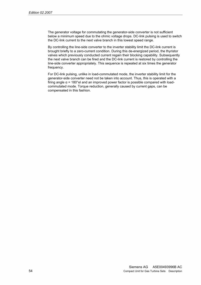
Edition 02.2007
Siemens AG A5E00493996B AC 54 Compact Unit for Gas Turbine Sets Description
The generator voltage for commutating the generator-side converter is not sufficient below a minimum speed due to the ohmic voltage drops. DC-link pulsing is used to switch the DC-link current to the next valve branch in this lowest speed range.
By controlling the line-side converter to the inverter stability limit the DC-link current is brought briefly to a zero-current condition. During this de-energized period, the thyristor valves which previously conducted current regain their blocking capability. Subsequently the next valve branch can be fired and the DC-link current is restored by controlling the line-side converter appropriately. This sequence is repeated at six times the generator frequency.
For DC-link pulsing, unlike in load-commutated mode, the inverter stability limit for the generator-side converter need not be taken into account. Thus, this is operated with a firing angle α = 180°el and an improved power factor is possible compared with load-commutated mode. Torque reduction, generally caused by current gaps, can be compensated in this fashion.

Edition 02.2007
Siemens AG A5E00493996B AC Compact Unit for Gas Turbine Sets Description 55
4 Description of the changeover device (option) As already explained, one of the main advantages of the static starting frequency converter is that various gas turbine sets can be started one after another using one converter.
An application example from a combined-cycle power station, where two compact units and two additional static excitation units are used for four gas turbine sets, is illustrated in Fig. 4.1
The gas turbine sets’ generators are each permanently assigned a static excitation unit while the starting frequency converter is first switched to a starting bus via an output isolator, which is subdivided by up to 2 changeover isolators. The changeover isolators can only be switched in manually from the main control room if there are no SFCs in operation.
The unit known as the changeover device is charged with coordinating the assignment between the starting frequency converters and the relevant gas turbine sets and their static excitation equipment.
The open-loop and closed-loop control signals within a compact unit are transferred between the SFC and SEE via the internal serial bus link.
Signals are transferred between the static excitation equipment associated with various compact units and/or individual static excitation units for gas-turbine generators via a bus link.
The static excitation unit associated with the turbine set to be started has the "master" function and controls the changeover device by:
– Controlling the isolator on the generator side in the BAB cells and the primary circuit breaker of the excitation transformer (which is also the case without a changeover device)
– Selecting the available starting frequency converter via the bus link, which also provides the operating status ("ready" or "faulted").
The control associated with the selected SFC in turn controls:
– The internal SFC output isolator
– The SFC circuit breaker (which is also the case without a changeover device)
In the event of a fault on the bus link, the turbine sets to which a compact unit has been assigned can continue to be started.
All circuit breakers are also mutually interlocked using auxiliary contacts to prevent erroneous switching.

Edition 02.2007
Siemens AG A5E00493996B AC 56 Compact Unit for Gas Turbine Sets Description
Fig. 4.1 Circuit diagram for starting frequency converters with changeover device (4 gas turbines with 2 starting frequency converters)

Edition 02.2007
Siemens AG A5E00493996B AC Compact Unit for Gas Turbine Sets Description 57
01.2006 A5E00493996B_AB
02.2007 A5E00493996B_AC Edition 02.2007 consists of the following chapters:
Previous editions are listed below: Edition Internal item number
07.2005 A5E00493996B _AA
Chapter Changes Date of edition
1 Description of the compact unit 2nd revision 02.2007
2 Description of the static excitation equipment (SEE) 2nd revision 02.2007
3 Description of the starting frequency converter (SFC) 2nd revision 02.2007
4 Description of the changeover device 2nd revision 02.2007


Attachment A-3


General Electric International, Inc. PSDS Program Wed Feb 06 15:33:44 2008
WESTERN ELECTRICITY COORDINATING COUNCIL 2011 HS1B APPROVED BASE CASE
----Model---- Record --------- Bus -------- ID --------- Bus -------- CK Se genrou 14921 99991 MIR_CT1 16.50 1 1 1
-----------------------------------------------------------------------------
ld 2.364000 Mbase 285.0 lpd 0.300000 Pgen 231.0 lppd 0.224000 Qgen 54.4 lq 2.302000 Terminal voltage 0.000000 lpq 0.491000 Field voltage 0.0000 lppq 0.224000 ll 0.192000 ra 0.002160 tpdo 10.480000 tppdo 0.048000 tpqo 1.164000 tppqo 0.079000 s1 0.114000 s12 0.489000 h 5.210000 d 1.000000 rcomp 0.000000 xcomp 0.000000 accel 0.000000 pfd 0.000000 pkd 0.000000 pfq 0.000000 pkq 0.000000 speed 0.000000 angle 0.000000 dpfd 0.000000 dpkd 0.000000 dpfq 0.000000 dpkq 0.000000 dspeed 0.000000 dangle 0.000000

General Electric International, Inc. PSLF Program Wed Feb 06 15:35:52 2008 11hs1b_cc-pb1.sav
WESTERN ELECTRICITY COORDINATING COUNCIL
2011 HS1B APPROVED BASE CASE
JANUARY 12, 2007
genrou mbase 0.0 mbaser 0.0 99991 MIR_CT1 16.5

General Electric International, Inc. PSDS Program Wed Feb 06 15:40:32 2008
WESTERN ELECTRICITY COORDINATING COUNCIL 2011 HS1B APPROVED BASE CASE
----Model---- Record --------- Bus -------- ID --------- Bus -------- CK Se esst6b 14922 99991 MIR_CT1 16.50 1 1 1
-----------------------------------------------------------------------------
tr 0.000000 kpa 20.900000 kia 53.200001 vamax 5.600000 vamin -4.700000 kff 1.000000 km 1.000000 kg 1.000000 tg 0.040000 vrmax 5.600000 vrmin -4.700000 vmult 1.000000 oelin 0.000000 ilr 3.740000 kcl 1.000000 klr 30.000000 ts 0.000000 s0 0.000000 s1 0.000000 s2 0.000000 s3 0.000000 ds0 0.000000 ds1 0.000000 ds2 0.000000 ds3 0.000000

General Electric International, Inc. PSLF Program Wed Feb 06 15:41:47 2008 11hs1b_cc-pb1.sav
WESTERN ELECTRICITY COORDINATING COUNCIL
2011 HS1B APPROVED BASE CASE
JANUARY 12, 2007
esst6b mbase 0.0 mbaser 0.0 99991 MIR_CT1 16.5

General Electric International, Inc. PSDS Program Wed Feb 06 15:44:17 2008
WESTERN ELECTRICITY COORDINATING COUNCIL 2011 HS1B APPROVED BASE CASE
----Model---- Record --------- Bus -------- ID --------- Bus -------- CK Se pss2b 14923 99991 MIR_CT1 16.50 1 1 1
-----------------------------------------------------------------------------
j1 1.000000 k1 0.000000 j2 3.000000 k2 0.000000 vsi1max 0.500000 vsi1min -0.500000 tw1 10.000000 tw2 10.000000 vsi2max 2.000000 vsi2min -2.000000 tw3 10.000000 tw4 0.000000 t6 0.000000 t7 10.000000 ks2 0.960000 ks3 1.000000 t8 0.600000 t9 0.120000 n 1.000000 m 5.000000 ks1 20.000000 t1 0.140000 t2 0.014000 t3 0.140000 t4 0.014000 t10 0.000000 t11 0.000000 vstmax 0.100000 vstmin -0.100000 a 1.000000 ta 0.000000 tb 0.000000 ks4 1.000000 s0 0.000000 s1 0.000000 s2 0.000000 s3 0.000000 s4 0.000000 s5 0.000000 s6 0.000000 s7 0.000000 s8 0.000000 s9 0.000000 s10 0.000000 s11 0.000000 s12 0.000000 s13 0.000000 s14 0.000000 s15 0.000000

s17 0.000000 s18 0.000000 s19 0.000000 d0 0.000000 d1 0.000000 d2 0.000000 d3 0.000000 d4 0.000000 d5 0.000000 d6 0.000000 d7 0.000000 d8 0.000000 d9 0.000000 d10 0.000000 d11 0.000000 d12 0.000000 d13 0.000000 d14 0.000000 d15 0.000000 d16 0.000000 d17 0.000000 d18 0.000000 d19 0.000000

General Electric International, Inc. PSLF Program Wed Feb 06 15:45:23 2008 11hs1b_cc-pb1.sav
WESTERN ELECTRICITY COORDINATING COUNCIL
2011 HS1B APPROVED BASE CASE
JANUARY 12, 2007
pss2b mbase 190.0 mbaser 0.0 99991 MIR_CT1 16.5

General Electric International, Inc. PSDS Program Wed Feb 06 15:50:41 2008
WESTERN ELECTRICITY COORDINATING COUNCIL 2011 HS1B APPROVED BASE CASE
----Model---- Record --------- Bus -------- ID --------- Bus -------- CK Se ggov1 14924 99991 MIR_CT1 16.50 1 1 1
-----------------------------------------------------------------------------
r 0.004000 rselect 1.000000 tpelec 0.100000 maxerr 0.050000 minerr -0.050000 kpgov 18.400000 kigov 3.100000 kdgov 0.000000 tdgov 1.000000 vmax 1.000000 vmin 0.100000 tact 0.300000 kturb 1.240000 wfnl 0.196000 tb 0.590000 tc 0.000000 flag 0.000000 teng 0.000000 tfload 3.000000 kpload 2.000000 kiload 0.670000 ldref 10.000000 dm 0.000000 ropen 0.100000 rclose -0.100000 kimw 0.000000 pmwset 0.000000 aset 9999.000000 ka 100.000000 ta 0.000000 db 0.000000 tsa 1.000000 tsb 1.000000 rup 99.000000 rdown -99.000000 s0 0.000000 s1 0.000000 s2 0.000000 s3 0.000000 s4 0.000000 s5 0.000000 s6 0.000000 s7 0.000000 s8 0.000000 s9 0.000000 ds0 0.000000 ds1 0.000000 ds2 0.000000 ds3 0.000000

ds5 0.000000 ds6 0.000000 ds7 0.000000 ds8 0.000000 ds9 0.000000

General Electric International, Inc. PSLF Program Wed Feb 06 15:52:17 2008 11hs1b_cc-pb1.sav
WESTERN ELECTRICITY COORDINATING COUNCIL
2011 HS1B APPROVED BASE CASE
JANUARY 12, 2007
ggov1 mbase 234.0 mbaser 0.0 99991 MIR_CT1 16.5

General Electric International, Inc. PSDS Program Wed Feb 06 15:36:54 2008
WESTERN ELECTRICITY COORDINATING COUNCIL 2011 HS1B APPROVED BASE CASE
----Model---- Record --------- Bus -------- ID --------- Bus -------- CK Se genrou 14925 99992 MIR_ST1 13.80 2 1 1
-----------------------------------------------------------------------------
ld 2.700000 Mbase 83.2 lpd 0.301000 Pgen 68.0 lppd 0.209000 Qgen 15.2 lq 2.560000 Terminal voltage 0.000000 lpq 0.541000 Field voltage 0.0000 lppq 0.209000 ll 0.166000 ra 0.003900 tpdo 6.720000 tppdo 0.043000 tpqo 2.500000 tppqo 0.150000 s1 0.059000 s12 0.285000 h 2.360000 d 1.000000 rcomp 0.000000 xcomp 0.000000 accel 0.000000 pfd 0.000000 pkd 0.000000 pfq 0.000000 pkq 0.000000 speed 0.000000 angle 0.000000 dpfd 0.000000 dpkd 0.000000 dpfq 0.000000 dpkq 0.000000 dspeed 0.000000 dangle 0.000000

General Electric International, Inc. PSLF Program Wed Feb 06 15:37:41 2008 11hs1b_cc-pb1.sav
WESTERN ELECTRICITY COORDINATING COUNCIL
2011 HS1B APPROVED BASE CASE
JANUARY 12, 2007
genrou mbase 234.0 mbaser 0.0 99992 MIR_ST1 13.8

General Electric International, Inc. PSDS Program Wed Feb 06 15:42:21 2008
WESTERN ELECTRICITY COORDINATING COUNCIL 2011 HS1B APPROVED BASE CASE
----Model---- Record --------- Bus -------- ID --------- Bus -------- CK Se esac7b 14926 99992 MIR_ST1 13.80 2 1 1
-----------------------------------------------------------------------------
tr 0.000000 kpr 33.299999 kir 66.599998 kdr 0.000000 tdr 1.000000 vrmax 15.750000 vrmin -15.750000 kpa 2.000000 kia 10.000000 vamax 35.299999 vamin -28.200001 kp 0.000000 kl 10.000000 te 0.950000 vfemax 15.750000 vemin 0.000000 ke 1.000000 kc 0.710000 kd 1.780000 kf1 0.000000 kf2 1.000000 kf3 0.000000 tf 1.000000 e1 14.800000 se1 0.060000 e2 12.900000 se2 0.009000 spdmlt 0.000000 s0 0.000000 s1 0.000000 s2 0.000000 s3 0.000000 s4 0.000000 s5 0.000000 ds0 0.000000 ds1 0.000000 ds2 0.000000 ds3 0.000000 ds4 0.000000 ds5 0.000000

General Electric International, Inc. PSLF Program Wed Feb 06 15:43:27 2008 11hs1b_cc-pb1.sav
WESTERN ELECTRICITY COORDINATING COUNCIL
2011 HS1B APPROVED BASE CASE
JANUARY 12, 2007
esac7b mbase 373.0 mbaser 0.0 99992 MIR_ST1 13.8

General Electric International, Inc. PSDS Program Wed Feb 06 15:49:27 2008
WESTERN ELECTRICITY COORDINATING COUNCIL 2011 HS1B APPROVED BASE CASE
----Model---- Record --------- Bus -------- ID --------- Bus -------- CK Se pss2b 14927 99992 MIR_ST1 13.80 2 1 1
-----------------------------------------------------------------------------
j1 1.000000 k1 0.000000 j2 3.000000 k2 0.000000 vsi1max 0.500000 vsi1min -0.500000 tw1 10.000000 tw2 10.000000 vsi2max 2.000000 vsi2min -2.000000 tw3 10.000000 tw4 0.000000 t6 0.000000 t7 10.000000 ks2 2.120000 ks3 1.000000 t8 0.600000 t9 0.120000 n 1.000000 m 5.000000 ks1 5.000000 t1 0.250000 t2 0.040000 t3 0.250000 t4 0.040000 t10 0.180000 t11 0.030000 vstmax 0.100000 vstmin -0.100000 a 1.000000 ta 0.000000 tb 0.000000 ks4 1.000000 s0 0.000000 s1 0.000000 s2 0.000000 s3 0.000000 s4 0.000000 s5 0.000000 s6 0.000000 s7 0.000000 s8 0.000000 s9 0.000000 s10 0.000000 s11 0.000000 s12 0.000000 s13 0.000000 s14 0.000000 s15 0.000000

s17 0.000000 s18 0.000000 s19 0.000000 d0 0.000000 d1 0.000000 d2 0.000000 d3 0.000000 d4 0.000000 d5 0.000000 d6 0.000000 d7 0.000000 d8 0.000000 d9 0.000000 d10 0.000000 d11 0.000000 d12 0.000000 d13 0.000000 d14 0.000000 d15 0.000000 d16 0.000000 d17 0.000000 d18 0.000000 d19 0.000000

General Electric International, Inc. PSLF Program Wed Feb 06 15:50:15 2008 11hs1b_cc-pb1.sav
WESTERN ELECTRICITY COORDINATING COUNCIL
2011 HS1B APPROVED BASE CASE
JANUARY 12, 2007
pss2b mbase 15.6 mbaser 0.0 99992 MIR_ST1 13.8

General Electric International, Inc. PSDS Program Wed Mar 12 20:14:13 2008
WESTERN ELECTRICITY COORDINATING COUNCIL 2011 HS1B APPROVED BASE CASE
----Model---- Record --------- Bus -------- ID --------- Bus -------- CK Se ieeeg1 14928 99992 MIR_ST1 13.80 2 1 1
-----------------------------------------------------------------------------
k 20.000000 t1 4.500000 t2 2.000000 t3 0.939000 uo 0.100000 uc -0.100000 pmax 1.000000 pmin 0.000000 t4 0.100000 k1 0.530000 k2 0.000000 t5 0.110000 k3 0.470000 k4 0.000000 t6 0.000000 k5 0.000000 k6 0.000000 t7 0.000000 k7 0.000000 k8 0.000000 db1 0.000000 eps 0.000000 db2 0.000000 gv1 0.000000 pgv1 0.000000 gv2 0.000000 pgv2 0.000000 gv3 0.000000 pgv3 0.000000 gv4 0.000000 pgv4 0.000000 gv5 0.000000 pgv5 0.000000 gv6 0.000000 pgv6 0.000000 s0 0.000000 s1 0.000000 s2 0.000000 s3 0.000000 s4 0.000000 s5 0.000000 ds0 0.000000 ds1 0.000000 ds2 0.000000 ds3 0.000000 ds4 0.000000 ds5 0.000000

General Electric International, Inc. PSLF Program Wed Mar 12 20:15:50 2008 11hs1b_ptsb-pb1.sav
WESTERN ELECTRICITY COORDINATING COUNCIL
2011 HS1B APPROVED BASE CASE
JANUARY 12, 2007
ieeeg1 mbase 190.0 mbaser 0.0 99992 MIR_ST1 13.8


Attachment A-4


Evidence Of Site Control

Mirant Delta, LLC (formerly known as Southern Energy Delta, L.L.C.) owns the site as evidenced by the Grant Deed dated as of April 15, 1999. Grant Deed transmitted to California ISO on March 7, 2008; Linda Wright is holding it to add to this Interconnection Request.


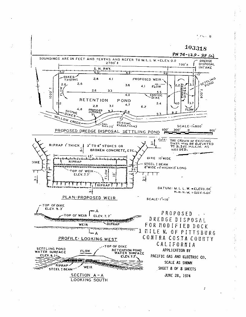


APPENDIX H2 MIRANT MOTION TO INTERVENE AND ANSWER

Mirant Corporation
601 13th Street, N.W., Suite 850N
Washington, DC 20005
T 202 585 3800 F 202 585 3806
U www.mirant.com
May 29, 2008
The Honorable Kimberly D. Bose
Secretary
Federal Energy Regulatory Commission
888 First Street, N.E.
Washington, D.C. 20426
RE: California Independent System Operator Corporation
Petition for Waiver of Tariff Provisions to Accommodate Transition to Reformed Large
Generator Interconnection Procedures, and Motion to Shorten Comment Period
Docket No. ER08-960-000
Dear Secretary Bose:
Please accept for filing in the above-referenced docket an electronically filed
“Motion to Intervene and Answer of Mirant Energy Trading, LLC, Mirant California, LLC, Mirant
Delta, LLC and Mirant Potrero, LLC.” Service has been made upon the service list as evidenced by
the attached certificate of service.
Thank you for your attention to this matter.
Sincerely,
David J. Reich
Director, Federal Regulatory Affairs
Mirant Corporation
Enclosures

UNITED STATES OF AMERICA
BEFORE THE
FEDERAL ENERGY REGULATORY COMMISSION
California Independent System Operator
Corporation
)
)
Docket No. ER08-960-000
MOTION TO INTERVENE AND ANSWER
OF MIRANT ENERGY TRADING, LLC, MIRANT CALIFORNIA, LLC,
MIRANT DELTA, LLC, AND MIRANT POTRERO, LLC
Pursuant to Rules 212, 213 and 214 of the Federal Energy Regulatory Commission’s
(“Commission”) Rules of Practice and Procedure, 18 C.F.R. §§385.212, 385.213 and 385.214 (2007),
and the Commission’s “Combined Notice of Filings #1” issued May 19, 2008, Mirant Energy Trading,
LLC (“MET”), Mirant California, LLC (“Mirant California”), Mirant Delta, LLC (“Mirant Delta”) and
Mirant Potrero, LLC (“Mirant Potrero”) (collectively, the “Mirant Parties”) jointly file this Motion to
Intervene and Answer in the above-referenced proceeding and, in support thereof, state as follows:
I. NOTICES AND COMMUNICATIONS
The persons to whom correspondence, pleadings, and other materials regarding this proceeding
should be addressed and whose names are to be placed on the Commission’s official service list on
behalf of the Mirant Parties are designated as follows, in accordance with Rule 203 of the
Commission’s Rules of Practice and Procedure, 18 C.F.R. §385.203:
Jonathan A. Sacks
Director, Business Development
Mirant Corporation
1155 Perimeter Center West
Atlanta, GA 30338
(678) 579-7739
David J. Reich
Director, Federal Regulatory Affairs
Mirant Corporation
601 13th Street, N.W., Ste. 850N
Washington, DC 20005
(202) 585-3817

2
II. INTERVENTION
MET, a Delaware limited liability company, is a power marketer primarily engaged in the
business of marketing electricity and other energy commodities at wholesale throughout North
America. MET is an indirect, wholly-owned subsidiary of Mirant Corporation, a publicly-traded
company. Mirant California is a Delaware limited liability company authorized to engage in the
marketing of electric energy and capacity and is the parent company of Mirant Delta and Mirant
Potrero. Mirant Delta is a Delaware limited liability company with a direct 100-percent ownership
interest in the Pittsburg and Contra Costa Power Plants, located in Pittsburg and Antioch, California,
which have an aggregate generating capacity of 1,985 MW. Mirant Potrero is a Delaware limited
liability company with a direct 100-percent ownership interest in the 362 MW Potrero Power Plant in
San Francisco, California. All of the Mirant Parties have received Commission authority to sell power
at market-based rates.1
The Mirant Parties move to intervene in this proceeding on the grounds that, as a marketer of
wholesale electricity and an owner, operator and potential developer of generating facilities within
California, they possess interests that may be directly affected by the outcome of this proceeding. The
Mirant Parties cannot be adequately represented by any other party in this proceeding.
III. BACKGROUND
On May 15, 2008, the California Independent System Operator Corporation (“CAISO”) filed a
“Petition for Waiver of Tariff Provisions to Accommodate Transition to Reformed Large Generator
Interconnection Procedures, and Motion to Shorten Comment Period” (“waiver petition”). According
to the CAISO, the waiver petition is the first step in a two-step process to reform the CAISO’s current
Large Generator Interconnection Procedures (“LGIP”) to allow the CAISO to more efficiently manage
its queue and be consistent with the development timelines for transmission assets and California’s
1 Mirant Americas Energy Marketing, L.P, et al., 111 FERC ¶ 61,252 (2005).

3
renewable portfolio standard requirements. The second step will involve filing an amendment to the
CASIO Tariff to incorporate the CAISO’s Generator Interconnection Process Reform (“GIPR”) by the
end of July 2008. The CAISO contends that the details of the GIPR are not necessary for the
Commission to grant the waiver petition.
The CAISO states that the requested waiver will operate to create three study groups: the
Serial Study Group, the Transition Cluster, and the Initial GIPR Cluster. According to the CAISO, the
waiver petition will allow the CAISO to immediately begin to expedite interconnections in the Serial
Study Group under current LGIP provisions. In order to be considered in the Serial Study Group an
interconnection request must meet three criteria. The interconnection request must either (1) be a late
stage interconnection request (i.e., system impact study results due by May 1, 2008), (2) have a
Purchase Power Agreement (“PPA”) approved or pending approval by the appropriate regulatory
authority; or (3) be an interconnection request, in queue order, seeking interconnection to new
transmission projects that have received necessary land use approvals from local, state, or federal
agencies, as applicable consistent with the transmission project’s studied capacity.
The Transition Cluster would include all validated interconnection requests received prior to
the opening of the CAISO’s first Queue Cluster Window on June 2, 2008. The Initial GIPR Cluster
will include all interconnection requests received during the Queue Cluster Window on or after June 2,
2008. The CAISO requests an immediate temporary suspension of all study activities for
interconnection requests in both the Transition Cluster and the Initial GIPR Cluster to facilitate the
transition to the GIPR and to allow the CAISO to concentrate its resources on processing the
interconnection requests in the Serial Study Group.
IV. ANSWER
The Mirant Parties agree that the CAISO has a problem with the size of its interconnection
queue and that action needs to be taken to resolve the existing backlog. However, the Mirant Parties
question whether the immediate and outright suspension of all work on the majority of pending

4
interconnection requests is integral to accomplishing the CAISO’s goal of clearing the interconnection
queue backlog.
The CAISO’s solution to stop all work on the Transition Cluster for at least two months while
it proposes new interconnection procedures that will not be implemented until some unknown time in
the future will add significant and costly delays to the projects being developed by Transition Cluster
interconnection customers. At best, project developers in the Transition Cluster might know by
September 29, 2008 (60 days after the July 31, 2008 GIPR filing date) when their projects might start
moving in the queue. There is no justifiable excuse for stopping all work on pending interconnection
requests however temporary the suspension might be and for the reasons tendered to the Commission
by the CAISO.
The CAISO does provide some general timelines in its waiver petition that it will complete the
initial Transition Cluster interconnection studies by July 2009, but it is not clear from the waiver
petition which interconnection studies the CAISO refers to – feasibility study, system impact study,
facility study or all of the above. Which studies the CAISO proposes to complete by that deadline is
critical to whether a project can advance through the power plant site certification process set forth by
the California Energy Commission (“CEC”). A completed application with the CEC requires that the
applicant have a completed system impact study or signed system impact study agreement with the
CAISO.2 Thus, delays in the CAISO study process, whether created by the status quo or the waiver
petition, can create serious delays in the CEC permitting process. Any needless delay in permitting
power plants in California will have serious repercussions for both developers that are attempting to
build in response to one of the many ongoing resource adequacy proposals tendered by load serving
entities (“LSEs”) in California and the LSEs that need the capacity to meet their state mandated
resource adequacy requirements.
2 See http://www.energy.ca.gov/2007publications/CEC-140-2007-003/CEC-140-2007-003.PDF at page 84.

5
Without the requisite studies or the execution of a system impact study agreement with the
CAISO developers cannot receive certification from the CEC to permit their generating plants, which
in turn will have adverse results for resource adequacy procurement in California. LSE’s will have
fewer bidders to choose from, less diversity of resources, and less certainty about project viability. In
addition, California will likely have far less capacity built than what is included in the CAISO queue.
The Mirant Parties believe that a simple solution exists that will avoid delaying the CEC
permitting process. If the Commission grants the CAISO’s waiver petition, the Commission must
condition the waiver petition upon the CAISO immediately offering system impact study agreements
for execution to Transition Cluster interconnection customers that have not been tendered this
agreement so that they may proceed with the CEC permitting process. The Mirant Parties request that
the Commission direct the CAISO to tender the system impact study agreements to Transition Cluster
interconnection customers that are not currently party to a system impact study agreement within 15
days of the date of the order granting the waiver petition.
Conditioning the waiver upon the tendering of a system impact study agreement by the CAISO
will not slow down the CAISO’s study of the Serial Study Group as the CAISO will not be required to
perform the system impact studies for the Transition Cluster group per the waiver request. Tendering a
system impact study agreement to a Transition Cluster interconnection customer is a simple
administrative task because the system impact study agreement in the CASIO’s LGIP is a pro-forma
agreement that does not require any effort on the part of the CAISO other than to fill in a few blanks.
The waiver petition notes that GIPR filing will address pending Transition Cluster
interconnection requests, some of which have already executed system impact study agreements, so all
Transition Cluster interconnection customers that execute the system impact study agreement are on
notice that their agreement may be superseded by the GIPR filing and any related deposit requirements
may be increased at that time. Granting this limited condition will serve two purposes, the CAISO will
still be able to proceed with its Serial Study Group analysis without disruption and Transition Cluster

6
projects will be able to proceed with their CEC permitting process without needless and unknown
delay.
V. CONCLUSION
WHEREFORE, for the foregoing reasons, the Mirant Parties request that the
Commission permit them to intervene in this proceeding and afford them all rights to participate as
parties to this proceeding. In addition, the Mirant Parties request that the Commission grant the relief
requested herein.
Respectfully submitted,
David J. Reich
Mirant Corporation
601 13th
Street, N.W., Suite 850N
Washington, D.C. 20005
(202) 585-3817
Dated: May 29, 2008

CERTIFICATE OF SERVICE
I hereby certify that I have this day served a copy of the foregoing document on each party
named in the official service list in this proceeding.
Dated at Washington, DC, this 29th
day of May 2008.
David J. Reich