appendix g erosion protection material evaluation … · armoring uranium mill tailings and covers:...
TRANSCRIPT

APPENDIX G EROSION PROTECTION MATERIAL EVALUATION

Cotter Corporation MWH Americas, Inc. i June 2011
TABLE OF CONTENTS 1.0 BACKGROUND ................................................................................................................. 1 2.0 EROSION PROTECTION MATERIALS ............................................................................ 1 3.0 REFERENCES ................................................................................................................... 3
TABLE
Table G.1 Riprap Sample Durability Scoring Summary
LIST OF ATTACHMENTS Attachment G.1 Results of Durability Testing Conducted by Lincoln DeVore in 1997 Attachment G.2 Results of Durability Testing Conducted by Advanced Terra Testing in
2011 Attachment G.3 Results of Petrographic Analysis Conducted by Petrographic Consultants
International, Inc. in 2011

Cotter Corporation MWH Americas, Inc. 1 June 2011
1.0 BACKGROUND
This appendix summarizes the characteristics of erosion protection materials to be used in reclamation of the tailings impoundments at the Cotter Corporation Canon City milling facility. Durability testing of potential riprap materials (conducted by Cotter Corporation) is summarized in this appendix. A portion of these test results were previously presented in the 2005 Decommissioning and Reclamation Plan (MFG, 2005). Additional testing conducted in 2011 is also presented in this appendix. 2.0 EROSION PROTECTION MATERIALS
This section presents the results of an evaluation of durability of a potential commercial source of riprap for erosion protection for tailings reclamation. This work was originally conducted by Cotter in 1998 and 1999, and has been updated in this appendix with the results of additional durability testing and a petrographic analysis. Laboratory results of additional testing and analysis are included in Attachments G.1 through G.3. Three areas of riprap materials are planned for tailings reclamation: (1) riprap on regraded embankment slopes, (2) riprap on select areas of the Primary and Secondary Impoundment cover slopes; and (3) riprap in diversion channels (where needed based on channel foundation conditions). MWH estimated that riprap with a D50 (median size) ranging from 1.4 to 4.0 inches would provide acceptable long-term erosional stability under extreme storm events on the regraded embankment and cover slopes. MWH estimated riprap with a D50 of 6 to 18 inches would provide long-term erosional stability for the diversion channels. Cotter evaluated sources of riprap based on material with a D50 of up to nine inches for both slope and channel applications. A commercial source of riprap near Canon City, T.H.E. Aggregate Source, was identified in 1998 by Cotter, and the material was sampled and tested for durability. Cotter plans to use this same rock source for this riprap. Cotter recently contacted T.H.E. Aggregate Source and they still have the similar material available in sufficient quantities. This appendix discusses the results of durability tests conducted in 1999, as well as the results of additional tests conducted in 2011. This testing has been done in accordance with the established durability criteria for uranium tailings reclamation documented by the U.S. Nuclear Regulatory Commission (NRC). Durability criteria. NRC recommendations for long-term durability of riprap are based on the specific tests and scoring summarized in Appendix D of NRC (1990), from literature review in Lindsey and others (1982) and primarily based on work documented in De Puy (1965). Table D1 (NRC, 1990) contains the scoring criteria for the commonly used durability tests (specific gravity, absorption, sodium sulfate, L.A. abrasion, Schmidt hammer, and splitting tensile strength). Scoring for the other tests (ultrasonic cavitation, freeze-thaw, scleroscope, coefficient of restitution, compressive strength, and sonic velocity) can be determined from De Puy (1965). In addition to the durability tests listed in Table D1, NRC (1990) specifies that, a petrographic examination of the rock sample should be performed by a geologist to determine the qualitative condition of the rock. Durability testing. Results of durability testing conducted on a rock sample from T.H.E. Aggregate Source conducted by Lincoln DeVore, Inc. in 1997 and by Advanced Terra Testing, Inc. (ATT) in 2011 are included as Attachments G.1 and G.2, respectively. The results of the

Cotter Corporation MWH Americas, Inc. 2 June 2011
tests conducted by Lincoln DeVore were part of correspondence provided by Cotter to CDPHE in 1999 (Cotter, 1999). The results of the tests conducted by ATT are provided for the first time herein. The test results are summarized below.
1. L.A. Abrasion (ASTM Method C 535), 21.3 percent loss after 1,000 revolutions. 2. Sodium sulfate soundness (ASTM Method C 88), 0.2 percent loss after 5 cycles. 3. Specific gravity (ASTM C 127); bulk specific gravity (saturated, surface dry): 2.61;
apparent specific gravity: 2.63. 4. Absorption (ASTM C 127), 0.3 percent. 5. Schmidt Hammer (ASTM D 5873) Rebound Hardness (including correction method):
44.77 (average) 6. Splitting Tensile Strength (ASTM D 3967): 1,330 psi
In order to be consistent with the scoring criteria in NRC (1990), the L.A. abrasion results were adjusted to a percentage loss after 100 revolutions. A linear adjustment was made, resulting in a percentage loss of 2.1 percent after 100 revolutions. The apparent specific gravity value (from the results above) was used in the scoring criteria. The test results above are summarized in Table G.1. The material was identified as an igneous rock and therefore weighting factors for an igneous rock were used for the scoring. Petrographic Analysis. NRC (1990) suggests conducting a petrographic analysis of the proposed riprap material in order to determine specific rock mineralogy and identify easily weathered minerals such as clay minerals. A petrographic analysis was conducted on the proposed riprap material by Petrographic Consultants International, Inc. (PCI). The report by PCI is included in Attachment G.3. In summary, PCI found the samples to be composed of two distinct lithologies of the Precambrian Pikes Peak Granite, a phaneritic crystalline pink microcline and gray quartz-rich granite, and a darker, finer-grained gneissic granite. PCI found the coarser granite to be “excellent material for rip rap”, scoring between 8 and 9 (on a scale of 1 to 10). The finer-grained banded gneissic granite material was also found to be suitable for riprap, but scored slightly lower, between 7 and 8. (PCI, 2011) Table G.1 Riprap Sample Durability Scoring Summary
Durability Test Test
Result Score Weighting Factors
(Igneous Rock)a Score x Weighting
Factorb L.A. abrasion (%) 2.1 9 1 9 Sodium sulfate soundness (%) 0.2 10 11 110 Specific gravity (units) 2.63 8 9 72 Absorption (%) 0.3 9 2 18 Splitting Tensile Strength (psi) 1,330 10 10 100 Schmidt Hammer 27.56 6 3 18 Petrographic Analysis 7.5e 7.5e 13 97.5 TOTAL SCORE ---- ---- ---- 424.5 MAXIMUM SCOREc ---- 10 49 490 ROCK QUALITY SCOREd ---- ---- ---- 86.6 a From Table D1 of NRC (1990) b Product of score and weighting factor c Product of maximum score and weighting factor d Sum of products of actual score and weighting factor divided by sum of products of maximum score and weighting
factor. e. The test result shown for the petrographic analysis is conservative, and assumes all riprap material is composed of
the less competent, banded gneissic granite.

Cotter Corporation MWH Americas, Inc. 3 June 2011
Discussion of test results. The durability test results in Table G.1 were converted to the nearest whole number score value. The corresponding score is listed in the Table G.1. The score is then multiplied by a weighting factor. The weighting factor is specific to each durability test and rock type (igneous, sandstone, limestone). The product of the durability test result score and the weighting factor is used to calculate a total rock quality rating. The rock quality rating is the sum of the weighted scores divided by the maximum possible score for the specific rock type tested and number of tests conducted. The rock quality rating calculations for the tested samples are summarized in Table G.1. Rock quality scores are used to determine acceptance of a rock sample for use as riprap, as well as to determine any requirements for oversizing. Riprap areas are designated as critical and non-critical areas. Critical areas include frequently saturated areas, all channels, poorly-drained toes and aprons, control structures, and energy dissipation areas (NRC, 1990). For critical areas, scores of 80 to 100 indicate riprap that is of acceptable quality and does not require oversizing, scores of 65 to 80 indicate riprap that is of acceptable quality but requires oversizing, and scores less than 65 indicates riprap of not acceptable quality. Non-Critical areas include occasionally-saturated areas, top slopes, side slopes, and well-drained toes and aprons (NRC, 1990). For non-critical areas, scores of 80 to 100 do not require oversizing, scores of 50 to 80 require oversizing, and scores of less than 50 are rejected. Oversizing is referred to as a percent increase in rock diameter based on the difference between a score of 80 and the actual score. For example, a sample with a score of 65 would require oversizing of 15 percent. This oversizing percentage is applied directly to the diameter of the riprap. The riprap borrow material source to be used for erosion protection materials at the site is an igneous rock, therefore the rock quality score was calculated for this rock type, as shown in Table G.1. The rock quality score is above 80, which indicates that this rock is of sufficient durability for use as riprap in both critical and non-critical areas, and does not require oversizing. Conclusions. Based on the preliminary evaluation by Cotter and the results of the analyses described above, the commercial rock source near Canon City can provide the particle size and quantity of riprap required under the updated plan for tailings impoundment reclamation. The test results and scoring calculations described above indicate that this material is of acceptable long-term durability. 3.0 REFERENCES
Advanced Terra Testing, Inc. (ATT). 2011. Results of Splitting Tensile Strength and Rock Hardness by Rebound Hammer Method. June 21.
Cotter Corporation (Cotter), 1999. Letter to Colorado Department of Public Health and
Environment, Hazardous Materials and Waste Management Division (Philip Stoffey) from David Munger concerning rock borrow source material, February 22.
De Puy, G.W., 1965. "Petrographic Investigations of Rock Durability and Comparisons of
Various Test Procedures," Engineering Geology, Vol. 2, No. 2, July. Lindsey, C.G., L.W. Long, and C.W. Begei, 1982. "Long-Term Survivability of Riprap for
Armoring Uranium Mill Tailings and Covers: A Literature Review," NUREG/CR-2642, prepared for U.S. Nuclear Regulatory Commission, June.

Cotter Corporation MWH Americas, Inc. 4 June 2011
MFG, Inc., 2005. 2005 Update of the Mill Decommissioning and Tailings Reclamation Plan for the Cotter Corporation Canon City Milling Facility. Prepared for Cotter Corporation. August.
Petrographic Consultants International, Inc. (PCI). 2011. Petrography of Pikes Peak Granite,
Canon City, Fremont County, Colorado: An Assessment of Suitability for Riprap Material. June 21.
U.S. Nuclear Regulatory Commission (NRC), 1990. “Final Staff Technical Position, Design of
Erosion Protective Covers for Stabilization of Uranium Mill Tailings Sites.” August.

ATTACHMENT G.1
Results of Durability Testing Conducted by Lincoln DeVore in 1997


ATTACHMENT G.2
Results of Durability Testing Conducted by Advanced Terra Testing in 2011


ATTACHMENT G.3
Results of Petrographic Analysis Conducted by Petrographic Consultants International, Inc. in 2011

Petrography of Pikes Peak Granite,
Canon City, Fremont County, Colorado:
An Assessment of Suitability for
Riprap Material
Prepared for
MWH Americas, Inc.
Ft. Collins, Colorado
Paula L. Hansley
Petrographic Consultants International, Inc.
545 West Fir Way, Louisville, CO 80027
June 21, 2011

Introduction
This report has been prepared to assess the suitability of the Precambrian Pikes Peak Granite for riprap material at the request of MWH Americas (MWH Project No. 1007533). The conclusions presented in this document are the results of visual examination of slabs of the granite and microscopic examination of thin sections of the granite. Due to the extreme variability in grain size and mineralogy of the granite, both binocular microscope and petrographic microscope examination were used for examination. Three pieces of granite of different textures and colors were chosen for slabbing. The flat slabs measure approximately 3 x 6 cm., 2.5 x 5 cm, and 8 cm x 10 cm and were examined by hand lens and the binocular microscope. Four granite samples of varying textures were chosen for thin sections (each, 2 cm x 4 cm) and studied by the petrographic microscope.
Summary
The Precambrian Pikes Peak Granite in most of the slabs and thin sections is the familiar, coarsely crystalline pink microcline- and gray quartz-rich granite of the Pikes Peak batholith. The other pieces are of a darker, finer grained gneissic granite facies that is marginal to the main Pikes Pike Granite intrusion. All pieces of granite are from a granite quarry in an outlier of Pikes Peak Granite in the Canon City embayment (Heinrich, 1948). The bulk of the pink granite is composed of microcline (potassium feldspar) grains that range up to 10 mm in diameter and create a tightly interlocking texture with smaller (up to seven mm) gray quartz grains. Subordinate minerals are plagioclase feldspar, biotite and trace amounts of primary and secondary minerals. Very little porosity is present. The pores are micropores, which, for the most part, are not interconnected, and have been created by the leaching of plagioclase feldspar. Secondary albite feldspar overgrowths precipitated on the original plagioclase feldspar grains before leaching, and these albite overgrowths give the granite more competency around the pores where plagioclase once existed. Numerous dolomite-, silica-, kaolinite-, and breccia-filled microfractures were found in the granite. These microfractures are sinuous, much less than one mm wide, and, in some samples, they are sub parallel. Open, sub parallel microfractures may be the result of blasting. The gneissic granite is composed of alternating biotite-rich and microcline/quartz-rich layers and is much finer grained than the pink granite.
Conclusions The coarse-grained, pink microcline- quartz-rich facies of the Pikes Peak Granite is a very competent rock and is judged to be excellent material for riprap, just below the quality of a fresh granite. Figure 1 is a subjective assessment of the suitability of the pink facies of the Pikes Peak granite for riprap material. This

granite was not deemed to be a “10” because of numerous microfractures, leaching and clay alteration of plagioclase, and occurrence of varying amounts of kaolinite. No swelling clays are present. The microfractures afford pathways for ground water to seep into the rock and could potentially cause either mechanical (i.e., freezing and thawing) breakdown of the rock or chemical weathering by leaching and alteration of plagioclase and other labile grains. Despite the microfractures, the granite was ranked high because the fractures are very thin and are commonly cemented by hard, relatively insoluble minerals such as quartz and dolomite. Furthermore, very few fractures are open. Dolomite and silica have increased the competency of the rock by filling many fractures. Dolomite is a better cementing agent than calcite because it has a small solubility product (Ksp) with values ranging from 10-17 to 10-19, whereas calcite has a much higher Ksp value of 10-8.35 (Krauskopf and Bird, 1995). The higher solubility product of calcite means that, under most conditions, calcite will be leached more readily than dolomite. Where kaolinite and brecciated granite are in microfractures, the rock is not as strong, because neither cements the edges of the fracture together. The banded (dark-light) gneissic facies of the Pikes Peak Granite is not considered to be quite as competent a riprap material as the pink facies, because it has a relatively high percentage (14.3%) of biotite compared to that (3.7%) of the pink granite. Due to its high iron content, biotite leaches and oxidizes (depending on the conditions) more readily than microcline or quartz. In addition, the micaceous cleavage of the biotite provides a pathway for potentially mineral-destructive solutions to travel through the granite. The gneissic facies, therefore, is not quite as competent as the pink facies of the granite. The gneissic granite is quite fresh, however, and a subjective assessment of its suitability for riprap material evaluates it as being only slightly less suitable for riprap than the pink facies of the granite (Figure 1).

Estimated Suitability for Rip Rap Use1 0___________________________________10 I I I I Bentonite Clay- Pikes Granite
Cemented Peak Massive Sandstone Granite2 Basalt 1See “Conclusions” 2Pink microcline- quartz-rich facies Figure 1.

1
Appendix 1: Quality Assurance
During the course of sample analysis and report preparation, every effort has been made to ensure that the character and integrity of the granite is safeguarded. Only personnel who are technically qualified and specifically trained in the handling and analysis of geological samples, such as “hard-rock” granitic specimens, have conducted the analytical procedures. Our analytical techniques are “state of the art” and are constantly updated, as new techniques become available. Petrographic Consultants will promptly correct any errors of omission or fact upon notification by the client. Interpretation of analytical results is the sole responsibility of Petrographic Consultants International, Inc. and are subject to revision, as new data become available.
Methods Petrography The granite slabs to be examined were chosen by the petrographer and then cut with a diamond saw to expose fresh, flat surfaces. Samples to be examined in thin section with the petrographic microscope were chosen and then cut with a diamond saw, ground to about 30 microns on a lapidary wheel, and final polishing was completed with a fine diamond saw and by hand. The slabs and thin sections were stained for identification of potassium feldspar by sequential etching over HF acid and staining in barium chloride and sodium cobaltinitrate (Bailey and Stevens, 1960). Plagioclase feldspar, although present, was not stained, for, in the experience of the author, this stain is unreliable. The section was also stained with a mixture of Alizarin red-S and potassium ferricyanide for identification of calcite and ferroan carbonates (Dickson, 1966). For clarity of examination under the petrographic microscope, the thin sections were covered with a very thin glass cover slip temporarily adhered to the thin section surface by vegetable cooking oil. The granitic slabs were examined using 10x and 20x hand lenses and a Spencer binocular stereo microscope. A Canon digital camera was used for the digital color photomicrographs of the granite slabs. Thin sections were examined using a Leica Ortholux II petrographic microscope. Photomicrography was done using a Nikon Coolpix 5000 automatic digital camera mounted on top of the petrographic microscope. Photomicrographs were calibrated by use of an E. Leitz Wetzlar stage micrometer with a 0.01 mm graduated scale. Point counts were made by inserting the thin section into a thin section holder, which was attached to the microscope stage. The holder was adjusted so that the slide would move in increments (small to large) according to the grain size of the sample so that the modal analyses would be representative of the sample. Points were recorded by punching the appropriate mineral button on a Lab-Count Denominator.

2
Point counts consisted of 300 points per thin section. Folk (1974) recommended for purposes of statistical accuracy that at least 300 points are necessary to reflect the mineralogy of a sample in a modal analysis. Holes in the granite are called “vugs”. Vugs in this granite are secondary micropores created by the leaching of plagioclase feldspar grains. These pores, therefore, are generally no larger than the size of the original plagioclase feldspar grain (<one to five mm). Although Folk (1974) recommends that up to 1,000 points in vugs be counted per thin section to most accurately assess the amount of porosity, this amount of point-counting is cost prohibitive. Furthermore, when porosity consists of very small moldic pores formed by grain dissolution as in this study, the percentage of porosity acquired from 300 grain-pore counts is close enough to the true porosity to be statistically meaningful.

Appendix 2
Descriptions of Pikes Peak Granite
Stained and Unstained Slabs

1
Slab Descriptions
Slab 1. Fine-grained pink and gray relatively fresh Pikes Peak Granite. The granite is mostly composed of pink microcline grains up to 10 mm in diameter and gray quartz up to three mm in diameter with subordinate plagioclase and biotite (~five percent). The plagioclase is <two cm in diameter and it has been weathered and leached; therefore, it cannot be easily seen in this slab. Sub parallel white dolomite veins (~1/2 mm wide) cut across all grains.
Field length, top: 5 cm. Slab 1, unstained. Pink microcline (M), gray quartz, and small, disseminated grains of biotite. White dolomite veins cut across the slabs.

2
Field length, bottom: 8 cm. Slab 1, stained. Abundant yellow microcline grains (M) and gray quartz grains. Sparse, discontinuous, white dolomite veinlets. Biotite and iron oxides cannot be seen due to the stain. This slab is the mirror image of the unstained slab.

3
Slab 2 Gneissic facies of the Pikes Peak Granite. This slab is very fine grained and consists of layers of biotite-rich granite alternating with pink/gray microcline- and quartz-rich, biotite-poor granite. In the dark gneissic granite, pink microcline and biotite are abundant; there is less quartz and plagioclase than in the pink facies. Sparse dolomite veinlets cut through both the dark and pink facies of the granite.
Field length, bottom: 3.5 cm Slab 2, unstained. Weathered gneissic facies of Pikes Peak Granite. Black areas are biotite rich, white are quartz rich, and pink are microcline rich. White veinlets are dolomite, and some veins have brecciated material.

4
Field length, bottom: 3.5 cm. Slab 2, stained. Microcline is stained yellow; biotite is black, and quartz-rich areas are white. Crosscutting white veinlets are dolomite. The stain obscures some of the mineralogy. This sample is the mirror image of the unstained slab 2.

5
Slab 3
Field length, bottom: 3.5 cm. Slab 3, unstained. Very coarse grained pink microcline (M) - and gray quartz (Q) - rich facies of the Pikes Peak Granite. Microcline grains are up to eight cm in diameter; quartz grains are from 1/2 to 2 cm in diameter. Plagioclase grains are up to two cm in diameter and constitute <5 percent of the granite. Biotite is not visible. Orange-brown areas of iron oxides have resulted from the weathering of biotite grains. The black arrow points to one of many very thin fractures that cut through the granite. Some of the white microfractures are filled with secondary silica; others are filled with secondary dolomite.

6
Field length, bottom: 8.0 cm. Slab 3, stained: This slab has been stained with potassium ferricyanide for ease of potassium feldspar identification. Microcline has picked up the stain and, therefore, is yellow. Gray grains are quartz (Q). The black arrows point to microfractures, which have been filled with secondary quartz. Brown material in the granite is iron oxides that have formed during the weathering of biotite and other minerals that contain iron. This slab is approximately the mirror image of the unstained slab.
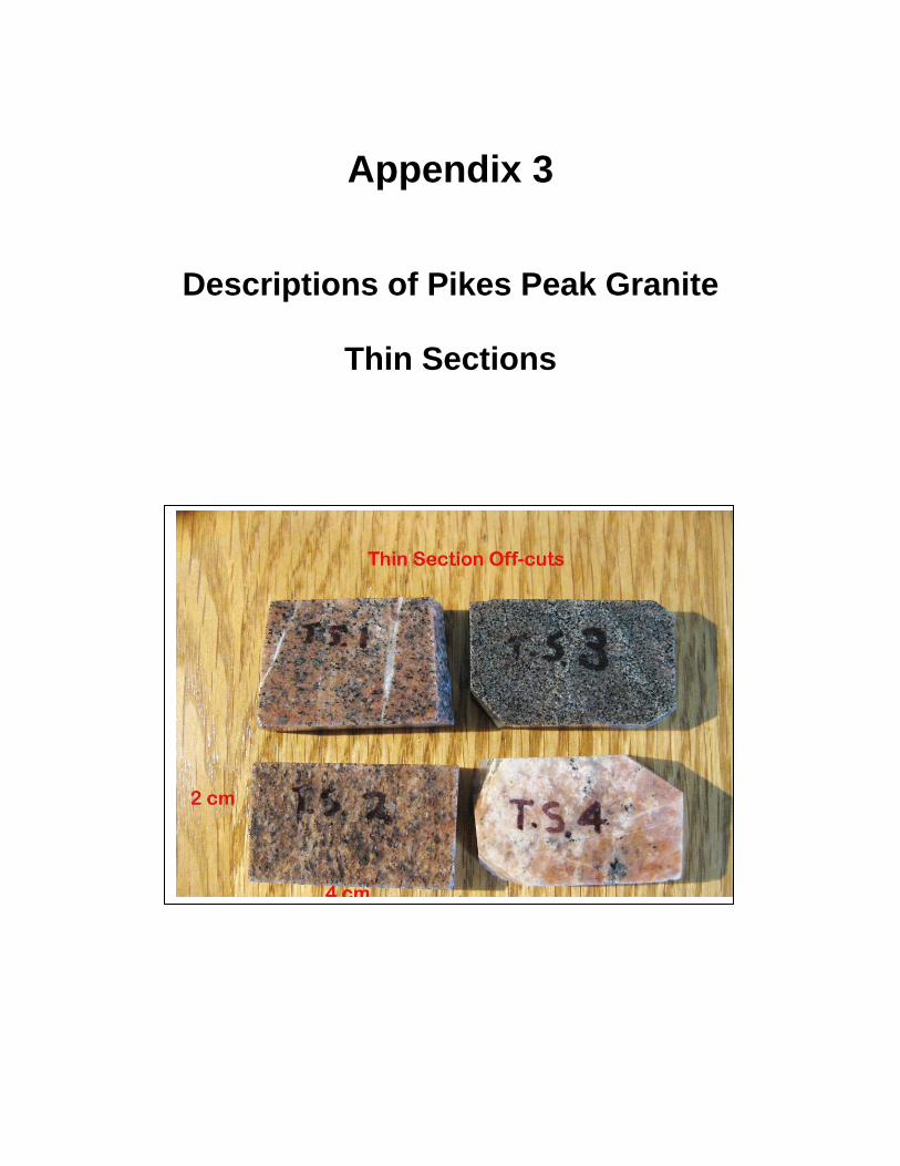
Appendix 3
Descriptions of Pikes Peak Granite
Thin Sections

1
Thin Section #1. Pikes Peak Granite Description of thin section: Very coarse grained; fresh potassium feldspar (microcline), quartz and minor plagioclase and biotite; slightly more altered than thin section #2 – many microcline grains show albitization and leaching; sub parallel microfractures filled with dolomite and(or) chert; moldic porosity has been created by leaching of plagioclase. Microfractures: Dolomite – Brecciated pieces of granite and dolomite in fracture; up to
one mm wide; sometimes include chert.
Mineralogy Primary Nonopaque minerals Quartz – Anhedral grains up to three mm wide; inclusions in microcline. Microcline – Twinned grains up to five mm in diameter; most have been partly replaced by albite and some have small albite overgrowths. Plagioclase – Untwinned and albite twinned grains up to three mm (most are less than one mm) in diameter; untwinned grains are commonly leached and(or) replaced by dolomite; albite overgrowths; much less common than microcline. Biotite – Yellowish brown to dark brown pleochroism; disseminated, fresh, micaceous grains, .25 to .75 mm long; < 5%. Muscovite – Colorless; 2nd order birefringence; micaceous grains, .1 to 2 mm long; <1%. Pyroxene – Colorless; 3rd order birefringence; moderately high relief; two grains, .25 mm in diameter. Opaque minerals Secondary Nonopaque minerals Albite – Colorless; upper first order birefringence; replaced parts of most microcline grains; overgrowths on plagioclase and (less commonly) microcline.

2
Thin Section #1 (cont.) Secondary (cont.) Nonopaque minerals (cont.) Dolomite – Colorless; 4th order birefringence; high differential relief; patches (.1 to .6 mm) replaced plagioclase; very common in microfractures; also rhombic grains, locally replaced by calcite. Chert – Microcrystalline; low 1st order birefringence; in microfractures with dolomite. Kaolinite – Colorless; very low birefringence; clay size; replaced plagioclase grains and carbonate; trace. Calcite – Colorless; 3rd order birefringence; replaced dolomite; <<1%. Sericite – Colorless; 2nd order birefringence; clay size; minor replacement of plagioclase (<1%). Opaque minerals Magnetite – Black; small secondary grains occur in many biotite grains. Discussion: Very similar in composition to thin sections #2 and #4. Very little porosity. The only vugs are where plagioclase grains have been leached, so the vugs are less than 3 mm in diameter and generally not interconnected.

3
Thin section #1. Vertical dolomite-filled fractures cut through twinned microcline grain. White grain is quartz in upper right; black areas are micro-pores. Field length (long dimension), 1.0 mm. Thin section #1. Kaolinite (K) and a pore or vug (V) are in the place of a former plagioclase feldspar grain. Biotite, b; dolomite, D; quartz, Q. A dolomite-filled microfracture cuts through the twinned microcline (Kf)
on the left. Crossed polarizers, field length (long dimension), 1.0 mm.

4
Thin section #2. Pikes Peak Granite Description of thin section: Relatively fresh, coarse-grained quartz, potassium feldspar (primarily microcline), plagioclase, biotite, and a trace of muscovite. Secondary minerals include dolomite, kaolinite, calcite, and albite. Small vugs occur in untwinned plagioclase. Microfractures: Quartz/dolomite – Dolomite has partly replaced quartz in
microfractures.
Mineralogy Primary Nonopaque minerals Quartz – Anhedral grains up to four mm in diameter; inclusions in orthoclase. Potassium feldspar – Most is grid-twinned microcline; the rest is untwinned orthoclase; grains are fresh and up to 10 mm in diameter. Plagioclase – Untwinned and albite-twinned grains up to two mm in diameter; most grains show dissolution; dolomite, kaolinite, and calcite partly fill dissolution vugs; rare albite overgrowths surround altered grains. Biotite – Yellow-brown to dark brown pleochroism; deep adsorption; micaceous cleavage; fresh grains. Muscovite – Colorless; 2nd order birefringence; up to one mm long; micaceous cleavage; trace. Opaque minerals Secondary Nonopaque minerals Dolomite – Colorless; 4th order birefringence; high differential relief in comparison to calcite; sub rhombic grains; replaced locally by calcite. Calcite – Colorless; 3rd order birefringence; in microfractures and plagioclase where it has replaced dolomite, trace. Kaolinite – Colorless to brown; very low 1st order birefringence; clay size; alteration product of plagioclase.

5
Thin Section #2 (cont.) Secondary (cont) Nonopaque minerals (cont.) Albite – Colorless; clear; 1st order white birefringence; overgrowths on altered, untwinned plagioclase grains. Quartz – Colorless; in thin (<10 microns) microfractures; replaced by dolomite. Discussion: Very similar in composition to thin sections #1 and 4. A point count was not done, because of the similarity of this sample to #1. This sample contains more carbonate than the other granite samples. It has very little porosity; vugs have been created where plagioclase grains have been leached and are less than two mm in diameter. Thin section #2. Clay (kaolinite) is a secondary alteration product of plagioclase feldspar. An albite overgrowth (Ao) formed on plagioclase as the clay was forming. Crossed polarizers, 100x, field length (long dimension), 1.0 mm.

6
Thin section #2. This piece of granite is composed of fresh biotite, quartz, and microcline. Only plagioclase (lower left)
shows minor secondary alteration to dolomite (d). Crossed polarizers, 40x, field length (long dimension) is 3.5 mm. Thin section #2. Brecciated material (quartz, dolomite, microcline) fills a microfracture through microcline (Kf). Crossed polarizers, 100x, field length (long dimension) is 1.0 mm.

7
Thin Section #3. Gneissic Pikes Peak Granite Description of thin section: Biotite-rich, fine-grained facies of Pikes Peak Granite; dark and light minerals are layered (gneissic); much finer grained and darker than granite in the other thin sections; equigranular; secondary kaolinite in vugs, albite overgrowths, and silica in microfractures; no carbonate; moldic porosity in tiny vugs in leached plagioclase grains; a trace of pyrite is present. Microfractures: Silica – Very thin (10 to 50 microns); commonly sub parallel.
Mineralogy Primary Nonopaque minerals Quartz – Most grains are ~.3 mm in diameter; tiny vugs in some grains. Potassium feldspar – Both orthoclase and microcline are present; not as much microcline as in #1 or #2; grains vary form .3 to 1.2 mm in diameter; rare, small albite overgrowths. Plagioclase feldspar – Untwinned and twinned grains from .2 to .6 mm in diameter; most grains show leaching; kaolinite in secondary vugs; albite overgrowths on some grains. Biotite – Light to dark brown pleochroism; micaceous; fresh; abundant. Secondary Nonopaque minerals Kaolinite – Colorless; very low birefringence; clay size; in secondary vugs in altered plagioclase grains. Albite – Colorless; upper first order white birefringence; overgrowths on feldspars. Silica – In some microfractures. Opaque minerals Pyrite – Black; one cube, .4 mm in diameter.

8
Thin section #3 (cont.) Discussion: This facies of the Pikes Peak Granite was called “an injection gneiss” by Heinrich, 1948). Heinrich said that this facies is quite common in this area and was formed as the granitic magma intruded into biotite-rich facies of the Idaho Springs Formation. See modal analysis, Appendix 4. Porosity in this sample is micro porosity created when plagioclase has been leached. Pores are generally not connected. Thin section #3. Albite overgrowth (Ao) around area that once held a plagioclase grain, which has been partly leached and partly converted
to kaolinite. Kaolinite, K; quartz, Q; microcline, Kf; biotite, B. Crossed polarizers, 100x, field length (long dimension), 1.0 mm.

9
Thin section #3. The Pikes Peak Granite has an equigranular texture in this sample. Quartz, Q; microcline, Kf; and biotite (B). Crossed polarizers, 25x, field length (long dimension) is 4.2 mm. Thin section #3. This granite contains more biotite (dark brown) than the other samples. Microcline is yellow-green and quartz is white. Plane-polarized light, 25x, field length (long dimension) is 4.2 mm.

10
Thin Section #4. Pikes Peak Granite Description of thin section: Very coarse grained; primarily quartz and microcline; small moldic pores are present where plagioclase grains have been leached; microfractures are filled with kaolinite and granite/dolomite breccia. Microfractures: Kaolinite – Sinuous; up to 200 microns wide; mixed with dolomite;
continuous; many. Dolomite – Dolomite with granite breccia; up to 50 microns wide.
Mineralogy Primary Nonopaque minerals Quartz – Anhedral grains up to seven mm in diameter; subrounded inclusions in feldspar. Potassium feldspar – Microcline (most) and orthoclase grains up to three mm in diameter; quartz inclusions. Plagioclase feldspar – Untwinned and albite-twinned grains up to five mm in diameter; most grains have dissolution vugs, which contain dolomite or kaolinite; albite overgrowths; much less common than potassium feldspar. Biotite – Medium brown to dark brown grains, ~.3 mm long; micaceous; two grains. Secondary Nonopaque minerals Dolomite – Colorless; 4th order birefringence; high differential relief; sub rhombic grains (~100 microns or less); replaced chert in fractures; present in the cores of many plagioclase grains. Kaolinite – Very low birefringence; clay size; replaced plagioclase grains; in microfractures. Albite – Colorless; upper 1st order white; a few overgrowths on highly altered plagioclase; some overgrowths enclose a vug.

11
Thin section #4 (cont.) Discussion: A point count of this thin section was not done because it is so similar to thin section #1. The only porosity exists where plagioclase grains have been leached; therefore, pores are less than five mm and are generally not interconnected. Thin section #4. Red arrow points to dolomite, which partly filled a microfracture in microcline. Crossed polarizers, 100x, field length (long dimension), 1.0 mm.

12
Thin section #2. Kaolinite has replaced almost all of the dolomite (D), which formerly filled the microfracture in microcline. Quartz, Q. Crossed polarizers, 100x, field length (long dimension) is 1.0 mm. Thin section #2. Kaolinite has filled a microfracture in quartz and fractured microcline (green) grains (red arrows). Crossed polarizers, 100x, field length (long dimension) is 1.0 mm.

Appendix 4
Modal Analyses of Petrographic Thin Sections Values are percentages based on counts of 300 points per thin section.
Mineral Thin Sec. 2 Thin Sec. 3 Quartz 45.4 45.5 K-feldspar 25 25.2 Plagioclase 15 10.9 Biotite 3.7 14.3 Muscovite 0.3 0 Calcite 4 0 Kaolinite 3 1.9 Albite 0.3 0 Quartz, sec. 0 0 Vugs 3.3 2.2

Appendix 5
References
Bailey, E. H. and R. E. Stevens, 1966, Selective staining of K-feldspar and plagioclase on rock slabs and thin sections: The American Mineralogist, v. 45, 1020-1025. Dickson, J.A.D., 1966, Carbonate identification and genesis as revealed by staining: Journal of Sedimentary Petrology, v. 36, p. 491-505. Folk, R., L., 1974, Petrology of sedimentary rocks. Austin, Texas: Hemphill’s Book Store, 182 pp. Heinrich, E. Wm., 1948, Pegmatites of Eight Mile Park, Fremont County, Colorado: The American Mineralogist, vol. 33, p. 420-448 and p. 550-588. Krauskopf, Konrad B. and Dennis K. Bird, 1995, Introduction to Geochemistry (3rd ed.), McGraw-Hill, Inc., New York, 647 p.