appendix e requirements to and examples of cutting tool drawings d1.pdf · ·...
TRANSCRIPT

Appendix E
Requirements to and Examples of Cutting Tool
Drawings
There are no big problems, there are just a lot of little problems.
Henry Ford, My Life and Work – An Autobiography of Henry Ford
Abstract. This Appendix argues that probably the most important stage in the
implementation of optimized tool geometry is its assigning on the tool drawings. To assign
this tool geometry properly, a tool designer should be a well-seasoned specialist with an
advanced degree having a broad knowledge in the design, manufacturing, implementation,
failure analysis, and many other surrounding subjects. As this is not the case today, the
common flaws with exemplification of some common tool drawings are discussed. The
Appendix sets the basic requirements of tool drawings with examples of proper tool
drawings.
E.1 Introduction
In the author’s opinion, the inadequate cutting tool drawings practice is the most
important issue affecting tool design, manufacturing and performance although not
many specialists in the tool industry as well as end users realize this problem.
Moreover, manufacturing and process engineers, for example in automotive plants,
are used to the existing tool drawings and do not see any problem with them so that
there is no sense of urgency to change or to improve these important documents.
An engineering drawing is a type of drawing that is technical in nature, used to
define fully and clearly requirements for engineered items, and is usually created in
accordance with standardized conventions for layout, nomenclature, interpretation,
appearance (such as typefaces and line styles), size, etc. Its purpose is to capture
accurately and unambiguously all the geometric features of a product or a
component. The end goal of an engineering drawing is to convey the all required
information that will allow a manufacturer to produce that component; an inspector
to properly inspect the produced component and thus fill an inspection report;

546 Geometry of Single-point Turning Tools and Drills
a user to verify if the component is suitable for its application; a maintenance
specialist to maintain the components in working conditions; and an application
specialist to carry out a reliability and/or failure analysis (if failure occurs).
Therefore, an engineering drawing should be a self-sufficient engineering
document which contains all the information needed over the manufacturing and
service time of a product. As a saying goes, “You can't staple your tongue to the
drawing” – it must say it all.
Drawings convey the following critical information:
Geometry the shape of the object; represented as views, how the object
will look when it is viewed from various standard directions, such as front,
top, side, etc.
Dimensions the size of the object is captured in accepted units.
Tolerances the allowable variations for each dimension and shape.
Material represents what the item is made of and its properties with
reference to the corresponding standard(s).
Finish specifies the surface quality of the item, functional or cosmetic.
Ideally, it should contain all information on surface integrity parameters
needed to intended part performance.
E.2 Tool Drawings – the Existant Practice
Unfortunately, there is a definite lack of information on cutting tool drawing
available in the literature on tool design. Moreover, according to the existing in
industry practice, a tool designer may not be even an engineer but rather a
draftsman with a community college education with some practical experience.
Moreover, application and tool performance specialists in many tool manufacturing
companies do not have advanced degrees.
According to existing notions [1, 2], the practice of tool design is as follows.
Once the necessary concept and descriptive information have been transmitted to
the tool designer via the tool order, concept sketch, the existing drawing (with
some comments) and verbal communication from the ordering department, it
becomes a tool designer responsibility to communicate adequately with the
toolmaker. The primary medium of that communication is the formal tool drawing.
As recommended [1, 2], beyond standard drafting practice, tool designers should
observe the following practices to assist in communications and reduce tool cost:
1. Tool drawing should describe the tool completely and also specify optimal
construction wherever possible.
2. Tool tolerances should be specified as loosely as possible, with every
attempt made to avoid extremely tight tolerances.
3. Tool drawing should be dimensioned completely so the scaling is not
required by toolmakers.
Appendix E: Requirements to and Examples of Cutting Tool Drawings 547
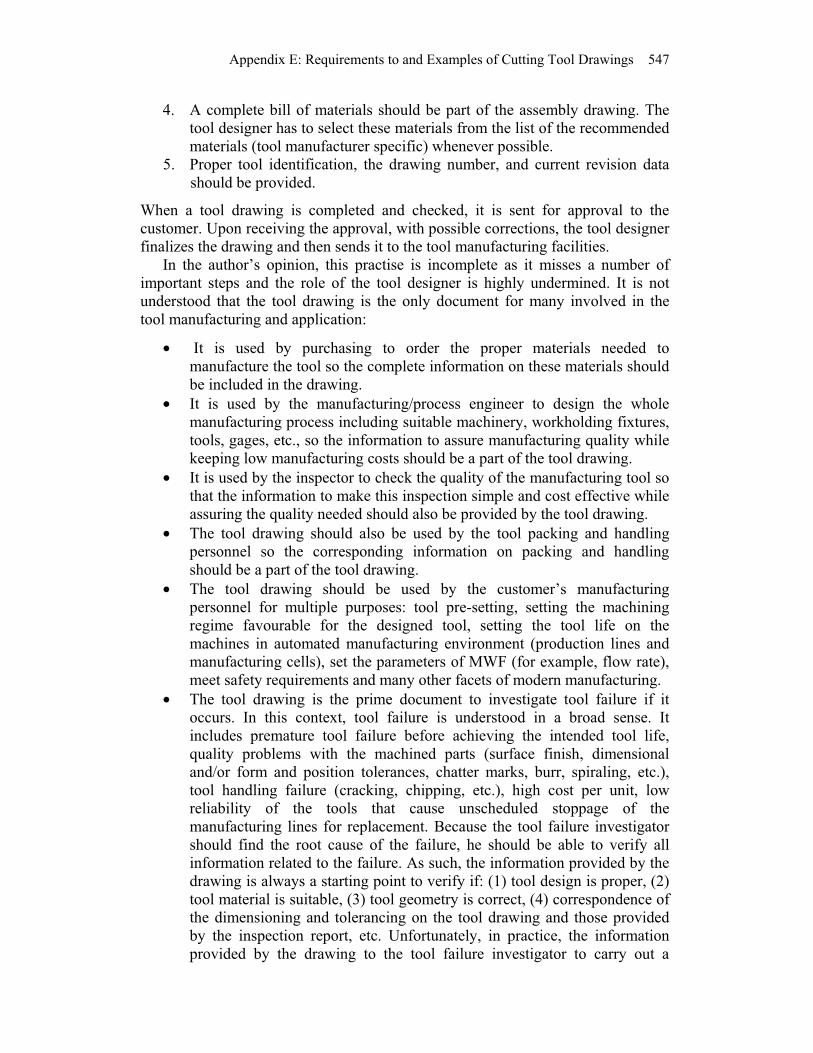
4. A complete bill of materials should be part of the assembly drawing. The
tool designer has to select these materials from the list of the recommended
materials (tool manufacturer specific) whenever possible.
5. Proper tool identification, the drawing number, and current revision data
should be provided.
When a tool drawing is completed and checked, it is sent for approval to the
customer. Upon receiving the approval, with possible corrections, the tool designer
finalizes the drawing and then sends it to the tool manufacturing facilities.
In the author’s opinion, this practise is incomplete as it misses a number of
important steps and the role of the tool designer is highly undermined. It is not
understood that the tool drawing is the only document for many involved in the
tool manufacturing and application:
It is used by purchasing to order the proper materials needed to
manufacture the tool so the complete information on these materials should
be included in the drawing.
It is used by the manufacturing/process engineer to design the whole
manufacturing process including suitable machinery, workholding fixtures,
tools, gages, etc., so the information to assure manufacturing quality while
keeping low manufacturing costs should be a part of the tool drawing.
It is used by the inspector to check the quality of the manufacturing tool so
that the information to make this inspection simple and cost effective while
assuring the quality needed should also be provided by the tool drawing.
The tool drawing should also be used by the tool packing and handling
personnel so the corresponding information on packing and handling
should be a part of the tool drawing.
The tool drawing should be used by the customer’s manufacturing
personnel for multiple purposes: tool pre-setting, setting the machining
regime favourable for the designed tool, setting the tool life on the
machines in automated manufacturing environment (production lines and
manufacturing cells), set the parameters of MWF (for example, flow rate),
meet safety requirements and many other facets of modern manufacturing.
The tool drawing is the prime document to investigate tool failure if it
occurs. In this context, tool failure is understood in a broad sense. It
includes premature tool failure before achieving the intended tool life,
quality problems with the machined parts (surface finish, dimensional
and/or form and position tolerances, chatter marks, burr, spiraling, etc.),
tool handling failure (cracking, chipping, etc.), high cost per unit, low
reliability of the tools that cause unscheduled stoppage of the
manufacturing lines for replacement. Because the tool failure investigator
should find the root cause of the failure, he should be able to verify all
information related to the failure. As such, the information provided by the
drawing is always a starting point to verify if: (1) tool design is proper, (2)
tool material is suitable, (3) tool geometry is correct, (4) correspondence of
the dimensioning and tolerancing on the tool drawing and those provided
by the inspection report, etc. Unfortunately, in practice, the information
provided by the drawing to the tool failure investigator to carry out a

548 Geometry of Single-point Turning Tools and Drills
failure analysis is normally incomplete and often misleading. As a result,
the tool manufacturer is always blamed for any tool failure even though
this failure may have little to do with the tool itself.
To be able to provide the listed information on the tool drawing to optimize tool
design accounting for the particular application conditions and requirements, the
tool designer should be a well-seasoned specialist with an advanced degree and
with a decisive voice in any tool manufacturing company. Unfortunately, this is not
the case today.
E.3 Tool Drawing Requrements
Tool drawings additionally should:
General: Compliance with the drawing standards (ISO) and with the
Drawing Manual set by the customer; compliance with ISO Standards on
tolerances and fits.
Specific: Compliance with ISO Standards on tool geometry and with
particular requirements set by the customer.
Performance: As a tool drawing is actually a set of drawings that includes a
tool layout, the machining regime and the intended tool life should be
indicated. In future, the cutting tool R&R (repeatability and
reproductibility) standards should be developed.
The first and foremost feature that must appear on any tool drawing is the datum
[3 5] which distinguishes a drawing from a sketch (picture). In order to ensure the
quality of tool produced, the datum features should be clearly indicated. It assures
proper inspection, selection of the proper tool holder, pre-setting, and tool proper
performance. In reality, however, this is not the case as the vast majority of tool
drawings stored in the tooling database of automotive companies do not indicate
any datum and does not adhere (even partially) to the above requirements.
To exemplify the last point, consider a few examples of drawing of tool
common in the automotive industry. Figure E.1 shows a drawing of the most
common PCD cartridge, Fig. E.2 shows a drawing of a typical PCD reamer, and
Fig. E.3 shows a drawing of a typical PCD interpolated milling tool as found in a
typical drawing database of an automotive company.
Although these tools are different and were designed by different well-known
tool manufacturing companies, there are a number of similarities what can be
observed in these drawings:
The datum is not indicated by any means that automatically downgrades
these drawings to pictures.
No tool geometry is shown according to the ISO [6] and/or ANSI [7]
standards for tool geometry. No edge preparation conditions are mentioned
(microgeometry parameters) although this is vitally important for PCD
tools.

Appendix E: Requirements to and Examples of Cutting Tool Drawings 549
Although all the shown tools are assemblages, no bill of material is
provided. In other words, no indication of the tool, tool shank, and brazing
filler materials are mentioned.
No shape and location tolerances are indicated including the runout of the
working part with respect to HSK holder as probably the most important
shape tolerance.
Fig. E.1. PCD cartridge
No surface finish is mentioned.
No particular sizes of PCD inserts, including their thickness as well as the
thickness of the carbide substrate are shown.
There is no indication of how the cutting inserts are secured in the body.
Technically, a paper glue can be used and this would not violate the
drawing requirements.
Many projections and cross-sections are not to the drawing standards.
For the reamer and the milling tools shown in Figs. E.2 and E.3, respectively, the
flute profiles are not dimensioned so that one may wonder whether there is enouth
space for chip evacuation. Moreover, the diameters and locations of the coolant
holes are not indicated. Although some means for balancing is graphically shown,
no one balancing procedure and/or requirement is set by these drawings.
TRANSMISSION CASE OP20-T04
AUTO CAD14
ZEICHNUNGSNUMMER:
NTC
130
010
20
30
60
40
50
70
80
90
100
120
110
MIL
LIM
ET
RE
SM
ET
RIC
-150
140 7.14
11.11
10°
42
28.49R0.
8
110°
3.5
10
36.81
7°
90°
15°
14
116 2.5
4.5
2.5
12
0.7
0.7
9.4
20°
5
13.72
TRANSMISSION CASE OP20-T01
PR
SIZE
TITLTITL
TITE
LOC
MAC
MAS
MAC
PTN
PTN
N_PART P_LEC P_DATE
F2 F
UNLES
KNOWLE
SH
Plane of projection needs to be
marked by a direction arrow.
DRAWING NO.
ENGINEERING PRINTS USED
DATE (DDMMYY)L.E.C.
SHEET SIZE:
DRAWING NO.:
DESIGNED BY:
DRAWN BY:
PART NO.:
GM ENG. APPROVED:
CHECKED BY:
Plant:METRIC
TOLERANCING ADDENDUM-2004BY THE GLOBAL DIMENSIONING AND
ASME Y14.5M - 1994 AS AMENDED DOCUMENT IS IN ACOORDANCE WITH
UNLESS OTHERWISE SPECIFIED THIS
UNLESS OTHERWISE SPECIFIED DIM'S. ARE IN
MILLIMETERS
DESCRIPTION:
PART NAME:
MACH. NAME:
MACH. NO.:
LOC.:
MANUAL CHANGESDO NOT MAKE
CDATE SYMREVISION/RECORD
AENDERUNG
(YYYYMMDD)DATE
CHANGE DESCRIPTIONSYM.

550 Geometry of Single-point Turning Tools and Drills
Fig. E.2. PCD reamer
Fig. E.3. PCD interpolation milling tool
13
00
10
20
30
60
40
50
70
80
90
10
012
01
10
MIL
LIM
ET
RE
SM
ET
RIC
-15
01
40
J1001676
(2 PCD TIPS)
(4 PCD TIPS)
VIEW A-A VIEW B-B
(4 PCD TIPS) (4 PCD TIPS)Ø 42.500±0.130
70°±2°15°
15°
50.00±0.13
24.00±0.13
1.00+0.26-0.00
Ø 39.56039.550
95.0
170.0
HSK-63A
(4 PCD TIPS)
C
C
B
B
A
A
(2 PCD TIPS)
VIEW C-C
120.00
20°
Ø 40.00739.997
Ø 42.500 ±0.130
120.00
VIEW C
Ø 39.5639.55
1.00+0.26-0.00
15°
170.0
VIEW A
NOTES:
PRIMARY CLEARANCE ANGLES: 10°
SECONDARY CLEARANCE ANGLES: N/A
(4) STRAIGHT FLUTES, STEEL BODY, HARDEN & GRIND
PUMP COVER OP. 50 - T2-2
R0.30±0.10
Ø 40.01440.009
N_PART P_LEC P_D
ENGINEERING PRINTS USED
DRAWING NO.
Plane of projection Symbol
DATE (DDL.E.C.
TOLERANCING ADDENDUM-20
SPECIFIED DIM'S. ARE INUNLESS OTHERWISE
UNLESS OTHERWISE SPECIFIED TDOCUMENT IS IN ACOORDANCE W
ASME Y14.5M - 1994 AS AMENDEBY THE GLOBAL DIMENSIONING A
MILLIMETERS
METRIC
DO NOT MAKMANUAL CHANG
PROJECTIONTHIRD ANGLE
TWO PLC. (X.XX) DIM'S. ±0.13ALL ANGULAR DIM'S. ±1/2°
ONE PLC. (X.X) DIM'S. ±0.3
ZERO PLC. (X) DIM'S. ±1
CDATE SYM
(YYYYMMDD)DATE
SYM.
(8) 2.5 Ø HOLES @45° TO C/L
260.0 (SET UP)
3.60±0.075
8.01
2.60±0.10
R0.4
Ø63.00
Ø53.00±0.13
+0.25
-0.00
45°
VIEW X
XØ100
TRANSMISSION CASE OP70-T06
13
00
10
20
30
60
40
50
70
80
90
10
01
20
11
0
MIL
LIM
ET
RE
S
ME
TR
IC -
15
01
40
NOTES:
PRIMARY CLEARANCE ANGLES: 10°
SECONDARY CLEARANCE ANGLES: N/A
PCD TIPS: STRAIGHT, NO BACKTAPER
(8) STRAIGHT FLUTES, R.H. CUT, STEEL BODY HDN. & GRIND
ZEICN_PART P_LEC P_DATE
Plane of projection needs to be
marked by a direction arrow.
DRAWING NO.
ENGINEERING PRINTS USED
DATE (DDMMYY)L.E.C.
SHE
DRA
DES
DRA
PAR
GM E
CHE
PlanMETRIC
TOLERANCING ADDENDUM-2004
BY THE GLOBAL DIMENSIONING AND ASME Y14.5M - 1994 AS AMENDED
DOCUMENT IS IN ACOORDANCE WITH
UNLESS OTHERWISE SPECIFIED THIS
UNLESS OTHERWISE
SPECIFIED DIM'S. ARE IN MILLIMETERS
DES
PAR
MAC
MAC
LOC
MANUAL CHANGESDO NOT MAKE
CDATE SYMREVISI
AENDE
(YYYYMMDD)DATE
CHANGE DSYM.
Appendix E: Requirements to and Examples of Cutting Tool Drawings 551
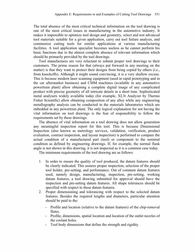
The total absence of the most critical technical information on the tool drawing is
one of the most critical issues in manufacturing in the automotive industry. It
makes it impossible to optimize tool design and geometry, select and test advanced
tool materials suitable for a given application, carry out tool failure analysis, and
commonize cutting tools for similar applications at various manufacturing
facilities. A tool application specialist becomes useless as he cannot perform his
basic functions due to the almost complete absence of relevant information which
should be primarily provided by the tool drawings.
Tool manufactures are very reluctant to submit proper tool drawings to their
customers. The prime reason for that (always put forward in any meeting on the
matter) is that they want to protect their designs from being copied by others (i.e.,
from knockoffs). Although it might sound convincing, it is a very shallow excuse.
This is because modern laser scanning equipment (used in rapid prototyping and in
the car aftermarket business) and CMM machines (available in any automotive
powertrain plant) allow obtaining a complete digital image of any complicated
product with precise geometry of all intricate details in a short time. Sophisticated
metal analysers widely available today (for example, XL3t Analyzer by Thermo
Fisher Scientific) allow obtaining composition of any alloy while any engineering
metallography analysis can be conducted in the materials laboratories which are
imbedded in any powertrain plant. The only logical explanation for not having the
vital information on tool drawings is the fear of responsibility to follow the
requirements set by these drawings.
The absence of vital information on a tool drawing does not allow generation
any meaningful inspection report for this tool. This is because Dimensional
Inspection (also known as metrology services, validation, verification, product
evaluation, contract inspection, and layout inspection) is performed to compare the
actual condition of a manufactured part (tool) or component to the nominal
condition as defined by engineering drawings. If, for example, the normal flank
angle is not shown in this drawing, it is not inspected as it is a common case today. The minimum requirements of the tool drawing are as follows:
1. In order to ensure the quality of tool produced, the datum features should
be clearly indicated. This assures proper inspection, selection of the proper
tool holder, pre-setting, and performance. Out of common datum features
used, namely design, manufacturing, inspection, pre-setting, working
datum features, a tool drawing submitted for approval should have the
inspection and pre-setting datum features. All shape tolerances should be
specified with respect to these datum features.
2. Proper dimensioning and tolerancing with respect to the selected datum
features. Besides the required lengths and diameters, particular attention
should be paid to the:
- Profile and location (relative to the datum features) of the chip-removal
flutes.
- Profile, dimensions, spatial location and location of the outlet nozzles of
the coolant holes.
- Tool body dimensions that define the strength and rigidity.
552 Geometry of Single-point Turning Tools and Drills
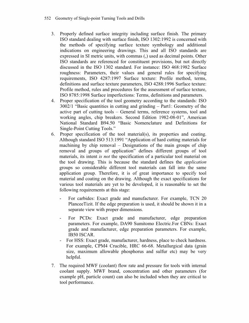
3. Properly defined surface integrity including surface finish. The primary
ISO standard dealing with surface finish, ISO 1302:1992 is concerned with
the methods of specifying surface texture symbology and additional
indications on engineering drawings. This and all ISO standards are
expressed in SI metric units, with commas (,) used as decimal points. Other
ISO standards are referenced for constituent provisions, but not directly
discussed in the ISO 1302 standard. For instance: ISO 468:1982 Surface
roughness: Parameters, their values and general rules for specifying
requirements, ISO 4287:1997 Surface texture: Profile method, terms,
definitions and surface texture parameters, ISO 4288:1996 Surface texture:
Profile method, rules and procedures for the assessment of surface texture,
ISO 8785:1998 Surface imperfections: Terms, definitions and parameters.
4. Proper specification of the tool geometry according to the standards: ISO
3002/1 “Basic quantities in cutting and grinding – Part1: Geometry of the
active part of cutting tools – General terms, reference systems, tool and
working angles, chip breakers. Second Edition 1982-08-01”, American
National Standard B94.50 “Basic Nomenclature and Definitions for
Single-Point Cutting Tools.”
6. Proper specification of the tool material(s), its properties and coating.
Although standard ISO 513:1991 “Application of hard cutting materials for
machining by chip removal – Designations of the main groups of chip
removal and groups of application” defines different groups of tool
materials, its intent is not the specification of a particular tool material on
the tool drawing. This is because the standard defines the application
groups so considerable different tool materials can fall into the same
application group. Therefore, it is of great importance to specify tool
material and coating on the drawing. Although the exact specifications for
various tool materials are yet to be developed, it is reasonable to set the
following requirements at this stage:
- For carbides: Exact grade and manufacturer. For example, TCN 20
PlanceeTizit. If the edge preparation is used, it should be shown it in a
separate view with proper dimensions.
- For PCDs: Exact grade and manufacturer, edge preparation
parameters. For example, DA90 Sumitomo Electric.For CBNs: Exact
grade and manufacturer, edge preparation parameters. For example,
IB50 ISCAR.
- For HSS: Exact grade, manufacturer, hardness, place to check hardness.
For example, CPM4 Crucible, HRC 66-68. Metallurgical data (grain
size, maximum allowable phosphorus and sulfur etc) may be very
helpful.
7. The required MWF (coolant) flow rate and pressure for tools with internal
coolant supply. MWF brand, concentration and other parameters (for
example pH, particle count) can also be included when they are critical to
tool performance.

Appendix E: Requirements to and Examples of Cutting Tool Drawings 553
For the drawing submitted for approval when new design is to be tested, the
additional information should include:
8. Suggested machining regime: cutting speed (spindle r.p.m.), cutting feed
(feed per revolution and feed per tooth for multi-tooth tools), depth of cut,
cycle diagram.
9. The required coolant flow rate and pressure to assure reliable chip removal
and intended tool life.
10. Criterion (criteria) of tool life and its assessment.
11. Expected tool life.
12. Tool reliability data. This important issue should be a subject to a special
meeting as one of the most important. This is because a prematurely failing
tool may cause a great losses. For example, on a transmission case line in
the automotive industry, a failed reamer causes up to 40 scraped cases and
1.5h lost in production time.
E.4 Examples of Tool Drawing
Figures E.4 E.8 show examples of tool drawings where the above-listed concepts
are realized. Figure E.4 shows a typical PCD cartridge as an example of single-
point tools. A simple comparison of this drawing with that shown in Fig. E.1
reveals the differences. First and foremost, datum A and datum B are assigned to
the base surface of the cartridge used for the tool location in the holder. The T-
hand-S geometry is specified according to the basic notions presented in Chap. 2.
Figure E.5 shows a drawing of a typical straight-flute drill used in the
automotive industry. The complete T-hand-S geometry is specified that makes the
tool grinding and inspection simple and straightforward. The longitudinal axis of
the tool shank is selected as the datum because this datum is actually the design,
manufacturing and working datum simultaneously. Particularities of the drill point
grind, location of the coolant holes, and flute geometry are completely specified.
The notes provide clear instructions including tool handling and shipping.
Figure E.6 shows a simple (due to the paper size limitation) yet common PCD-
tipped drill used in the automotive industry. As with other tools, the tool geometry
is completely described in the T-hand-S. The longitudinal axis of the tool shank is
selected as the datum because this datum is actually the design, manufacturing and
working datum simultaneously. Bill of materials shows the complete description of
the materials used to manufacture this tool. Important particularities of PCD tool
design are also shown in corresponding sections and views.
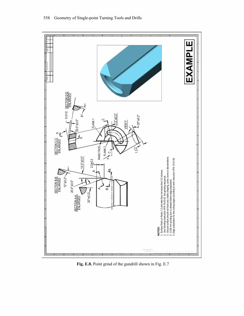
Figure E.7 shows a design of a high-penetration rate gundrill used in the
automotive industry. As it was an experimental tool, the complete description of
the conditions of its production testing as well as the expected tool life and
expected tool reliability are also shown on the drawing. Figure E.8 shows the T-
hand-S geometry of the terminal end of the drill used for its point grind.

554 Geometry of Single-point Turning Tools and Drills
0.0
02
0.1
6
10
±0
.02
0.0
02
A
6*
0.5
x4
5°
- 3 p
lc
1.2
x4
5°
15
°±0.5
°
14
-0.0
20 1.5
*
R0
.8±0
.1
42
35
°2
8.5
6.5
3.5
9.4
B
A0
.00
2
0.1
61
0°
10°
5°
10
°
8°
(PC
D in
se
rt)
10°
1
20
°
12
°(w
ith
in the
substr
ate
)1
.6*
2.6
*
20
°±0.3
°
5±0.1
5
0.7
0.7
12
7
11.2
R3.5
R5.6
NO
TE
S:
1.
PS
D inse
rt G
rad
e:
XX
X-X
X
M
ake:X
XX
XX
X
2. C
art
ridge
- A
ISI S
tee
l 10
45 H
RC
28-3
2, B
lack O
xid
e fin
ishin
g.
3. M
an
ufa
ctu
rer's r
eco
mm
ende
d: cuttin
g s
pe
ed 45
0 m
/min
c
uttin
g f
ee
d 0
.10 m
m/tooth
/rev
3. *
To
ol m
anufa
ctu
rer
specific
dim
en
sio
ns.
4.
Su
rface
fin
ish o
n t
he P
CD
insert
max R
a0.0
2
5. T
ole
rances o
n n
on-s
pecifie
d a
ngu
lar
dim
ensio
ns ±
1°.
6. S
urf
ace fin
ish
on n
on s
pecifie
d s
urf
eces m
ax R
a0.6
.
7. C
uttin
g tip
an
d its
ed
ges s
hould
not h
ave a
ny v
isib
le c
hip
pin
g, cra
cks o
r an
y o
ther
vis
ible
at x2
5 m
agnific
ation d
efe
cts
.
8.
Bra
zin
g n
ote
s:
Bra
ze
jo
int th
ickn
ess m
ax 0
.10 m
m; in
tera
ptions n
o m
ore
than 1
5%
of th
e join
t le
nght.
B
razin
g a
ccord
ing
to b
razin
g instr
uction X
XX
X-2
00
8 for
"PC
D"
toolin
g.
9. F
inal in
sp
ection
sho
uld
in
clu
de x
xxx-2
00
9 in
sp
ection
rep
ort
.
METRIC
DIM
EN
SIO
NS
IN
MM
TO
LE
RA
NC
ES
(EX
CE
PT
AS
NO
TE
D)
x
-
±0.5
x.x
-
±0.2
x.x
x
-
±0
.01
x°
-
0.5
°
TH
IS D
RA
WIN
G C
ON
TA
INS
CO
MM
ER
CIA
LL
Y C
ON
FID
EN
TIA
L A
ND
PR
OP
RIE
TA
RY
IN
FO
RM
AT
ION
BE
LO
NG
ING
TO
PS
MI
AN
D I
S N
OT
TO
BE
DE
SC
LO
SE
D W
ITH
OU
T F
IRS
T E
XE
RC
UT
ING
A
NO
N-D
ISC
LO
SU
RE
AG
RE
EM
EN
T W
ITH
RE
CIP
IEN
T
SC
ALE
MA
TE
RIA
L IN
FO
RM
AT
ION
:
TY
PE
HA
RD
NE
SS
SH
EE
T
O
F
RE
V
NO
TE
B
Y D
AT
E
0P
RE
-RE
LE
AS
EA
VP
11
C
Vie
w C
0.0
5A
B
0.0
5
I
IS
CA
LE
3:1
IIS
CA
LE
3:1
II
n.1
n.2
n.8
EX
AM
PL
E
Fig. E.4. PCD cartridge drawing – an example

Appendix E: Requirements to and Examples of Cutting Tool Drawings 555
A
Ø17
+0
.013
-0.0
33
60°±
0.5
°
B
B
Ø14
.48
-0.0
30
SE
CT
ION
B-B
EN
LA
RG
ED
1±0.3
O.A
.L.
NO
TE
S:
1. 0
.04
0 m
m I
NC
L. B
AC
KT
AP
ER
PE
R 2
5 m
m O
N D
IAM
ET
ER
17.4
82
. LA
RG
E D
IAM
ET
ER
IS
NO
N C
UT
TIN
G,
NO
SID
E C
LE
AR
AN
CE
OR
BA
CK
TA
PE
R IS
RE
QU
IRE
D3
. 0
.3 M
AX
. W
EB
TA
PE
R,
0.0
3 M
AX
. F
LU
TE
RU
NO
UT
4. B
UR
NIS
HIN
G M
AR
GIN
S +
0.0
-01
0 B
EL
OW
FIN
ISH
ED
17
.48 d
ia.
5.
LE
NG
TH
S A
ND
DIA
ME
TE
RS
TO
BE
ME
AS
UR
ED
TO
T.S
.C.
WIT
H N
O R
EG
AR
D T
O B
AC
KT
AP
ER
OR
UN
DE
RC
UT
7. T
OO
L M
AR
KIN
G T
O I
NC
LU
DE
TO
OL
#,
RE
VIS
ION
, M
AT
ER
IAL
, A
ND
DA
TE
.8
. C
UT
TIN
G T
IP A
ND
IT
S E
DG
ES
SH
OU
LD
NO
T H
AV
E A
NY
VIS
IBL
E C
HIP
S,
CR
AC
KS
OR
DE
FE
CT
S @
x2
59
F
INA
L I
NS
PE
CT
ION
SH
OU
LD
IN
CL
UD
E X
XX
X-2
00
9 I
NS
PE
CT
ION
RE
PO
RT
.
10.
TO
OL
S S
HO
UL
D B
E H
AN
DL
ED
WIT
H A
PL
AS
TIC
CA
P A
FT
ER
FIN
AL G
RIN
D.
6.
DIM
EN
SIO
NS
AN
D T
OL
ER
AN
CE
S N
OT
SP
EC
IFIE
D T
O B
E P
ER
XX
XX
XX
X T
OO
L M
AN
UF
AC
TU
RIN
G S
TA
ND
AR
DS
VIE
W E
0.0
05
A
0.0
10
A
Vie
w E
Ø2
.18
Ø5.7
9R
EF
.
2.4
2
CO
OL
AN
T G
RO
OV
E T
OIN
TE
RS
EC
T T
HR
U H
OLE
S
MA
TE
RIA
LS
(D
O N
OT
DE
VIA
TE
)C
arb
ide
: C
ER
AT
IZIT
MG
12
Co
ating
: T
i-B
2A
ER
O-L
AP
CO
NT
AC
T S
UR
FA
CE
SA
FT
ER
CO
AT
ING
0.0
2A
+0.1
4-P
LC
'S O
N1
4.4
8 D
IA
0.80
.15-0
.25
O.D
. R
EL
IF P
ER
SID
E
40°
EN
LA
RG
ED
SE
CT
ION
C-C
8°1+
0.2
+1°
25°±
2°
+0.1
+0.1
5
WE
B D
IA.
GA
SH
RA
DIU
SS
TA
RT
+3
°
C
C
160°±
1°
0.0
2A
DE
TA
IL II
EN
LA
RG
ED
PO
INT
GR
IND
AV
-1A
L
DE
T. II
DE
T. I
EN
LA
RG
ED
DE
TA
IL I
Su
rfa
ce R
ou
gh
ness
as p
er
ISO
13
02
Sta
nd
ard
(no
t w
ors
e t
han
)G
roun
d P
rim
e F
lan
ks
Ra
0.2
5S
econ
dary
Fla
nks
R
a 0
.4C
arb
ide M
arg
ins
R
a 0
.25
Flu
te
R
a 0
.15
(polis
h)
D
D
SE
CT
ION
D-D
EN
LA
RG
ED
20
080
127
SY
MR
ELE
AS
ED
AE
ND
ER
UN
GA
UT
HD
FT
CH
KA
PR
V
(YY
YY
MM
DD
)D
AT
EC
HA
NG
E D
ES
CR
IPT
ION
SY
M.
CH
GO
RD
ER
NU
MB
ER
CH
KB
YB
YA
PR
VB
Y
Ø2
0h6
130±1
.5
0.8
x45°
2-P
LC
'S
56±1.5
(S
HA
NK
LE
N.)
72.5
±1.5
(F
LU
TE
LE
N.)
50.7
2±0.1
3
0.6
20°
15°±
1°
0.3
2
0.0
025
-0.2
67°
100°±
2°
3.3
±0.1
5
2.9
°RE
F.
40°
4±0.1
Ø0.8
±0.1
R0.5
0.4
R0.8
±0.1
Ap
rx.1
Aprx
. R
1.5
1,32
2,67
EN
LA
RG
ED
DE
TA
IL III
He
lica
lseco
dary
relie
f-
2-P
LC
'S
SH
IPP
ING
LA
SE
R E
TC
H IN
TH
IS A
RE
A p
. 7
DE
T.
III
51°
RE
F.
EX
AM
PL
E1
1.
TO
OLS
SH
OU
LD
BE
PA
CK
ED
FO
R S
HIP
PIN
G A
CC
OR
DIN
G T
O U
RT
34
8 M
AN
UA
L.
TH
E S
HIP
PIN
G B
OX
SH
OU
LD
INC
LU
DE
A C
OP
Y O
F T
HE
FIN
AL
IN
SP
EC
TIO
N R
EP
OR
T.
Fig. E.5. Straight-flute carbide drill – an example

556 Geometry of Single-point Turning Tools and Drills
(not
wo
rse than)
Gro
un
d P
rim
e F
lan
ks R
a 0
.1S
eco
nd
ary
Fla
nks R
a 0
.4P
CD
Ma
rgin
s
R
a 0
.1C
arb
ide
Ma
rgin
s
R
a 0
.25
Flu
te
R
a 0
.15
0.6
±0
.05
0.6
±0
.05
1.5
±0
.1
PC
D in
se
rt1
5°
12°
SE
CT
ION
A-A
EN
LA
RG
ED
25
°
1.5
±0.1
PC
D in
sert
25°
SC
AL
E 1
0:1
EN
LA
RG
ED
SE
CT
ION
B-B
SC
ALE
5:1
II 1
I
EN
LA
RG
ED
SE
CT
ION
C-C
Su
rfa
ce
Ro
ug
hn
ess
as p
er
ISO
1302 S
tan
da
rd
CH
AN
GE
DE
SC
RIP
TIO
N
EN
LA
RG
ED
SE
CT
ION
D-D
(YY
YY
MM
DD
)D
AT
ES
YM
.N
UM
BE
RO
RD
ER
BY
CH
GB
YA
PR
VB
YC
HK
12. T
OO
LS
SH
OU
LD
BE
PA
CK
ED
FO
R S
HIP
PIN
G A
CC
OR
DIN
G T
O S
HM
45
MA
NU
AL. T
HE
SH
IPP
ING
BO
X S
HO
UL
D
INC
LU
DE
A C
OP
Y O
F T
HE
FIN
AL
IN
SP
EC
TIO
N R
EP
OR
T.
.
0.0
50
SH
IPP
ING
LA
SE
R
ET
CH
IN
TH
IS A
RE
A
6. D
IME
NS
ION
S A
ND
TO
LE
RA
NC
ES
NO
T S
PE
CIF
IED
TO
BE
PE
R X
XX
XX
TO
OL
MA
NU
FA
CT
UR
ING
ST
AN
DA
RD
S
11. T
OO
LS
SH
OU
LD
BE
HA
ND
LE
D IN
PL
AS
TIC
PR
OT
EC
TIV
E C
UP
S S
P 2
3 A
ND
SP
46 B
ET
WE
EN
OP
ER
AT
ION
S.
10 F
INA
L IN
SP
EC
TIO
N S
HO
ULD
IN
CLU
DE
QC
FE
30
09
-54
IN
SP
EC
TIO
N R
EP
OR
T.
9. C
UT
TIN
G T
IP A
ND
IT
S E
DG
ES
SH
OU
LD
NO
T H
AV
E A
NY
VIS
IBLE
CH
IPS
, C
RA
CK
S O
R D
EF
EC
TS
@ x
25
8. T
OO
L M
AR
KIN
G T
O IN
CLU
DE
TO
OL
#, R
EV
ISIO
N,
XX
XX
XX
XX
, D
AT
E,
AN
D P
HO
NE
#
7. B
RA
ZE
PE
RF
OR
ME
D A
CC
OR
DIN
G T
O X
XX
XX
TO
OL B
RA
ZIN
G IN
ST
RU
CT
ION
QC
BR
10
96 F
OR
"P
CD
" T
OO
LIN
G.
5. LE
NG
TH
S A
ND
DIA
ME
TE
RS
TO
BE
ME
AS
UR
ED
TO
T.S
.C. W
ITH
NO
RE
GA
RD
TO
BA
CK
TA
PE
R O
R U
ND
ER
CU
T
4. B
UR
NIS
HIN
G M
AR
GIN
+0
.0-0
13
BE
LO
W F
INIS
HE
D"P
CD
"Ø3
. 0.3
MA
X. W
EB
TA
PE
R, 0.0
3 M
AX
. F
LU
TE
RU
NO
UT
2. LA
RG
E D
IAM
ET
ER
IS
NO
N C
UT
TIN
G, N
O C
LE
AR
AN
CE
OR
BA
CK
TA
PE
R I
S R
EQ
UIR
ED
1. 0.0
008
/0.0
01
6 m
m T
OT
AL
BA
CK
TA
PE
R P
ER
10 m
m O
N C
UT
TIN
G D
IAM
ET
ER
S
Ø1
5.2
(C
arb
ide b
ody)
45°
0.5
±0.1
PC
D F
AC
E0.6
±0
.1 47
±0.8
1x4
5°
Vie
w F
Ø1
6h6
A
NO
TE
S:
BR
AZ
E F
ILL
ER
: L
UC
AS
- M
ILH
AU
PT
EA
SY
-FL
O 4
5P
CD
TIP
IN
SE
RT
S: IL
JIN
CX
L R
36
0/6
0.0
-1.6
PO
LIS
HE
DC
AR
BID
E B
OD
Y M
AT
'L:
RS
-40-5
0-1
5 C
ER
AT
IZIT
MG
12
MA
TE
RIA
L: D
O N
OT
DE
VIA
TE
25
°±3
°
Vie
w F
CO
OLA
NT
GR
OO
VE
TO
INT
ER
SE
CT
TH
RU
HO
LE
S
1.6
8 R
ef.
3 m
in.
5 m
in.
0.5
±0.1
PC
D F
AC
E
1.0
±0
.1
90
2±
0.2
5
0.5
17
.0±
0.1
3
5 m
in.
40
AB
D
Ø1
2.4
(C
arb
ide
bod
y)
Ø1
5.5
12
Ø1
5.5
00
A
90
°±0.5
°
91
.68
Re
f.
A
C
B
D
C
25°±
3°
2±
0.2
5
Ap
pro
x.1
5°
Sm
oo
th b
len
d
0.6
±0
.06
Cylin
drical m
arg
in
3.9
71±0.4
8°±
30'
Vie
w E
A
0.0
7±0
.07
Ø1
2.4
15
Ø1
2.4
03 0
.05
00
.05
0
0.0
50
15
0°
Ø1
.5±0
.02
A A
IV
SC
AL
E 5
:1
2 H
OLE
S III
MA
RG
IN G
RO
UN
D
EN
LA
RG
ED
Cylin
dri
ca
l m
arg
in
0.6
±0
.06
50°±
2°
VIE
W E
CY
LIN
DR
ICA
L
Ø5
.0
+0
.30
-0.0
0.6
±.0
6
RA
DIU
S
1.0
±0.1
SC
ALE
5:1
FIN
ISH
ED
PC
D D
ia.
+0
.0-0
13
BE
LO
W
95°±
1°
0.3
±0
.08
RA
DIU
S
50
.6°
RE
F.
IV
Ø0
.60
±0
.013
WE
B
EX
AM
PL
E
CH
ISE
L T
O E
XT
EN
D P
AS
T
CE
NT
ER
LIN
E .3
78
±0
.1
Fig. E.6. PCD-tipped drill – an example

Appendix E: Requirements to and Examples of Cutting Tool Drawings 557
0.25
NO
TE
S:
1. B
razi
ng a
ccor
ding
to X
XX
X w
ork
inst
ruct
ion
No.
XX
XX
for
the
tip a
nd N
o. X
XX
for
the
shan
k.
100
% q
ualit
y co
ntro
l acc
ordi
ng to
wor
k in
stru
ctio
n X
XX
-XX
X.
2. C
uttin
g ed
ges
shou
ld n
ot h
ave
any
visi
ble
chip
ping
, cra
cks
or a
ny o
ther
def
ects
@x2
5.3.
Pon
t grin
d V
PA
15-
07. A
fter
shar
peni
ng, t
ip s
houl
d be
han
dled
with
a p
last
ic c
up o
n it.
4. F
low
che
ck 1
00%
:. M
in 2
0 l/m
in a
t 7M
Pa.
Use
a w
ater
sol
uble
coo
lant
of 8
% c
once
ntra
tion.
5. T
orqu
e te
st 1
00%
:. T
estin
g to
rque
sho
uld
not b
e le
ss th
at 3
7Nm
.6.
Poi
nt g
rind
acco
rdin
g to
Grin
ding
Inst
ruct
ion
VP
A 1
5-03
-02.
7. F
inal
insp
ectio
n ac
cord
ing
to W
I 239
-08.
Insp
ectio
n re
port
- IR
578
-07.
8. T
ools
sho
uld
be p
acke
d fo
r sh
ippi
ng a
ccor
ding
to X
XX
-X m
anua
l. T
he s
hipp
ing
box
shou
ldin
clud
e a
copy
of t
he fi
nal i
nspe
ctio
n re
port
.
R 0
.06m
in
0.5a
prx 60°
95°
0.0
05
0.0
05
MA
RK
TO
OL
No.
Ø16
-0.0
12
DR
IVE
R:
ST
EE
L A
NS
I 4140 H
B280-3
00
BR
AZ
E F
ILLE
R:
XX
XX
X
SH
AN
K:
34
Cr6
Mo H
RC
40-4
2
TIP
: P
lansee T
izit
ca
rbid
e H
10T
- P
TH
0885-2
10
(2 P
LC
S. 1
80°
AP
AR
T)
14±
0.15
15
A0.
63
62
152
139
MA
TE
RIA
LS
(R
EF
ER
EN
CE
S)
M10
-1 T
HR
EA
D1.
5 D
EE
P*
1370
±1.
5
340
SM
OO
TH
BLE
ND
TO
TU
BE
OD
NO
ST
EP
S
0.00
5-0.
07 IN
CLU
DE
D.
BA
CK
TA
PE
R
PE
R T
IP L
EN
GH
T
Ø15
.5-0
.02
Ø7.
5 R
EF
.
2 P
LCS
1.5x
45°
p.1
E
Wor
k m
ater
ial -
alu
min
um 3
19
Rot
atio
nal s
peed
- 8
500
r.p.
m.
Fee
d ra
te -
100
0 m
m/m
in
Coo
lant
flow
rat
e -
min
15
l/min
Coo
lant
bra
nd X
XX
X, c
once
ntra
tion
- 9%
,
filtr
atio
n -
10 m
icro
met
ers,
pH
8.8
-9.5
tram
p oi
l < 4
%S
tart
ing
bush
ing-
spin
dle
alig
nmen
t < 0
.008
Exp
ecte
d to
ol li
fe -
500
0 ho
les
Exp
ecte
d re
liabi
lity
1 fa
ilure
per
50
drill
s
BE
XP
ER
IME
NT
AL
TO
OL
C
Ø8.
00-0
.07
CB0.0
05
0.0
05
B
R0.
5apr
x
120°0.2/
0.3
CH
AM
FE
R
RA
KE
FA
CE
0.08
43°
D
SY
M.
DA
TE
(YY
YY
MM
DD
)C
HA
NG
E D
ES
CR
IPT
ION
5±1
VIE
W E
EN
LAR
GE
D
NU
MB
ER
OR
DE
RB
YC
HK
BY
CH
GB
YA
PR
V
EN
LA
RG
ED
D30
°
SE
CT
ION
C-C
SE
CT
ION
D-D
EN
LAR
GE
D
0.08
0.20
/0.2
5C
YL.
LAN
D
+0.
010.
12
30
°
ALL
SU
PP
OR
TIN
G
AR
EA
S
EX
AM
PL
E
RA
DIA
L R
ELI
EF
R0.
1min
Fig. E.7. High-penetration rate gundrill – an example
558 Geometry of Single-point Turning Tools and Drills
(YY
YY
MM
DD
)D
AT
EC
HA
NG
E D
ES
CR
IPT
ION
SY
M.
CH
GO
RD
ER
NU
MB
ER
CH
KB
YB
YA
PR
VB
Y
EX
AM
PL
E
20.0
°±0.
5°
12.0
°±0.
5°
A
A
BB
12°±
0.3°
C
C
8°
D
D
SE
CT
ION
A-A
20°±
0.2°
12°±
0.2°
20°±
0.2°
1.3
F
VIE
W F
2.0±
0.2
FLA
NK
1
FLA
NK
2
NO
TE
S:
1.
Sur
face
fini
sh o
n fla
nks
1,2
and
rake
face
not
wor
se th
an 0
.2 m
icro
ns.
2. U
se G
rindi
ng In
stru
ctio
n V
PA
15-
03-0
2 th
e gr
indi
ng s
eque
nce.
3. G
roun
d su
rfac
e sh
ould
not
hav
e an
y vi
sibl
e ch
ippi
ng, p
ores
, bur
ns o
r di
scol
orat
ions
.
4. 0
.020
mm
grin
ding
bur
r is
allo
wed
bef
ore
edge
pre
para
tion.
5. E
dge
prep
arat
ion
for
the
cutti
ng e
dges
acc
ordi
ng to
wor
k in
stru
ctio
n V
PA
15-
41-0
8.
EN
LAR
GE
D
SE
CT
ION
B-B
EN
LAR
GE
D
RA
KE
FA
CE
+0.
2
20.0
°±0.
5°
SE
CT
ION
C-C
EN
LAR
GE
D
SE
CT
ION
D-D
EN
LAR
GE
D
Fig. E.8. Point grind of the gundrill shown in Fig. E.7
Appendix E: Requirements to and Examples of Cutting Tool Drawings 559
References
[1] Tanner JP (1990) Manufacturing Engineering: An Introduction to the Basic Functions.
2nd. ed. Marcel Dekker, New York
[2] Mutter CS (1996) Product tooling and equipment. In: J.M. Walker (Ed) Handbook of
manufacturing engineering. Marcel Dekker, New York
[3] Mathematical definition of dimensioning and tolerancing principles (1994) ASME
Standard Y14.5.1M-1994
[4] Geometrical Product Specification (GPS) – Masterplan. 1995, ISO.
[5] Meadows JD (1995) Geometric dimensioning and tolerancing. Marcel Dekker, New
York
[6] International Standard ISO 3002-1 Basic quantities in cutting and grinding. Part 1:
Geometry of the active part of cutting tools - general terms, reference systems, tool
and working angles, chip breakers. 1982.
[7] American National Standard ANSI B94.50-1975 Basic nomenclature and definitions
for single-point cutting tools. 1975 (reaffirmed 1993).