appendix e report of preliminary geotechnical …
TRANSCRIPT

D R A F T E N V I R O N M E N T A L I M P A C T R E P O R T B E L M O N T P O O L R E V I T A L I Z A T I O N P R O J E C T
L S A A S S O C I A T E S , I N C . A P R I L 2 0 1 6
P:\CLB1302\Public Review Draft EIR\App E - Geotechnical Evaluations.docx «04/08/16»
APPENDIX E
REPORT OF PRELIMINARY GEOTECHNICAL EVALUATION, GEOTECHNICAL INVESTIGATION, PRELIMINARY
GEOTECHNICAL REPORT, & SOIL CORROSIVIY EVALUATION

D R A F T E N V I R O N M E N T A L I M P A C T R E P O R T B E L M O N T P O O L R E V I T A L I Z A T I O N P R O J E C T
L S A A S S O C I A T E S , I N C . A P R I L 2 0 1 6
P:\CLB1302\Public Review Draft EIR\App E - Geotechnical Evaluations.docx «04/08/16»
This page intentionally left blank

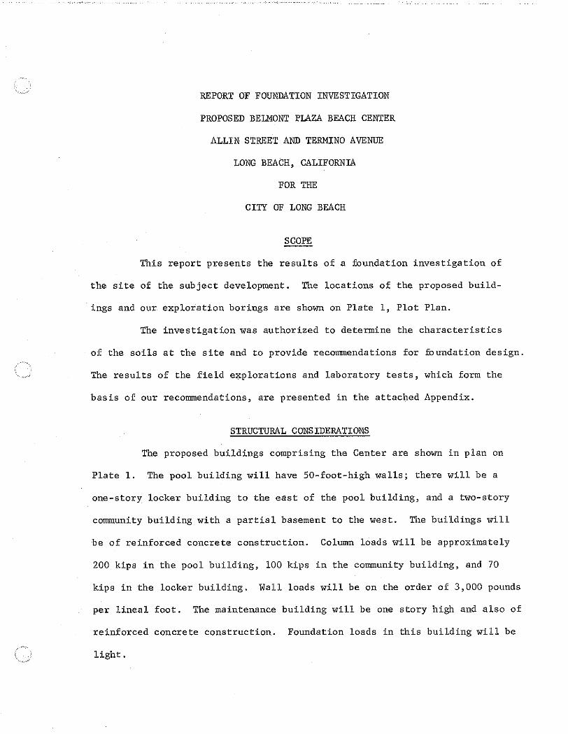
REPORT OF PRELIMINARY GEOTECHNICAL INVESTIGATION

REPORT OF PRELIMINARY GEOTECHNICAL INVESTIGATION
PROPOSED BELMONT PLAZA OLYMPIC POOL REVITALIZATION PROJECT
4000 EAST OLYMPIC PLAZA LONG BEACH, CALIFORNIA
Prepared for:
MDM ARCHITECTS, LLP
Pasadena, California
April 14, 2009
MACTEC Project 4953-09-0301
MACTEC

MACTEC Engineering and Consulting, Inc. 5628 East Slauson • Los Angeles, CA 90040-1554 • Phone: 323.889.5300 • 323.889-5398
April 14, 2009 Mr. Richard Dell MDM Architects, LLP 201 South Lake Avenue, Suite 413 Pasadena, California 91101 Subject: LETTER OF TRANSMITTAL Report of Preliminary Geotechnical Investigation
Proposed Belmont Plaza Olympic Pool Revitalization Project 4000 East Olympic Plaza Long Beach, California MACTEC Project 4953-09-0301
Dear Mr. Dell:
We are pleased to submit the results of our preliminary geotechnical investigation for the proposed Belmont Plaza Olympic Pool Revitalization project in Long Beach, California. This investigation was conducted in general accordance with our proposal February 26, 2009, as it was incorporated into the Agreement between Architect (Maple Dell + McClelland Architects, LLP) and Consultant (MACTEC Engineering and Consulting, Inc.) dated October 22, 2008. The Architect’s agreement (the Prime Agreement) dated October 21, 2008, with the City of Long Beach provides professional services that included geotechnical services for the Belmont Plaza Olympic Pool Revitalization project. Our services were provided in accordance the terms and conditions contained in those agreements. The scope of our services was planned with Mr. Marc Hauck of Maple Dell + McClelland Architects, LLP. Mr. Hauck provided us with information regarding the structural features of the existing structures. We have discussed the project with Mr. Jaime Garza of Miyamoto International, Inc., structural engineers for the project. The results of our investigation and design recommendations are presented in this report. Please note that our report only contains information for use in evaluating the existing structures at the site and for planning development and preliminary design for replacement structures.

Mr. Richard Dell April 10, 2009 Page 2
It has been a pleasure to be of professional service to you. Please call if you have any questions or if we can be of further assistance. Sincerely, MACTEC Engineering and Consulting, Inc.
Boris O. Korin Senior Engineer
Rosalind Munro Senior Geologist
Marshall Lew, Ph.D. Senior Principal Engineer Vice President P:\4953 Geotech\2009-proj\90301 Belmont Pool\4.1 Reports\4953-09-0301R01_04-15-09 DRAFT Belmont Plaza Pool.doc\ (7 copies submitted)

REPORT OF PRELIMINARY GEOTECHNICAL INVESTIGATION PROPOSED BELMONT PLAZA
OLYMPIC POOL REVITALIZATION PROJECT
4000 EAST OLYMPIC PLAZA LONG BEACH, CALIFORNIA
Prepared for:
MDM ARCHITECTS, AIA
Long Beach, California
MACTEC Engineering and Consulting, Inc.
Los Angeles, California
April 14, 2009
Project 4953-09-0301

Proposed Belmont Plaza Olympic Pool Revitalization Project April 15, 2009 MACTEC Engineering and Consulting, Inc., Project 4953-09-0301
ii
TABLE OF CONTENTS
EXECUTIVE SUMMARY ............................................................................................................... iii
1.0 SCOPE ................................................................................................................................... 1
2.0 PROJECT CONSIDERATIONS ........................................................................................... 3
3.0 EXPLORATIONS AND TESTING ....................................................................................... 4
4.0 GEOLOGY ............................................................................................................................ 5
5.0 LIMITED GEOLOGIC-SEISMIC HAZARDS EVALUATION ........................................... 6
6.0 LIQUEFACTION EVALUATION ........................................................................................ 7
7.0 RECOMMENDATIONS ....................................................................................................... 9 7.1 GENERAL ................................................................................................................ 9 7.2 FOUNDATIONS .................................................................................................... 10 7.3 SITE COEFFICIENT AND SEISMIC ZONATION .............................................. 11 7.4 FLOOR SLAB SUPPORT ...................................................................................... 11 7.5 RETAINING WALLS AND WALLS BELOW GRADE ....................................... 13 7.6 GRADING .............................................................................................................. 15 7.7 GEOTECHNICAL OBSERVATION ...................................................................... 17
8.0 GENERAL LIMITATIONS AND BASIS FOR RECOMMENDATIONS ......................... 18
9.0 REFERENCES .................................................................................................................... 19
FIGURES
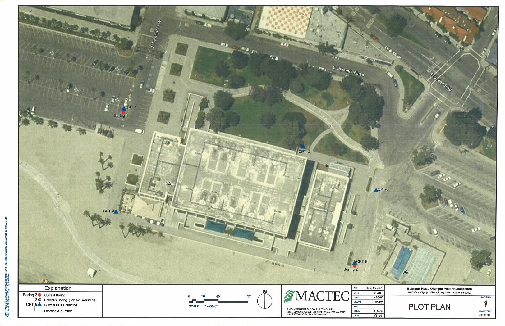
1 Plot Plan 2 Regional Geology 3 Regional Faults and Seismicity Map
APPENDIX A: EXPLORATIONS AND LABORATORY TESTS APPENDIX B: CONE PENETRATION TEST DATA APPENDIX C: CORROSION STUDY APPENDIX D: PRIOR REPORT OF GEOTECHNICAL INVESTIGATION
Proposed Belmont Plaza Olympic Pool Revitalization Project April 14, 2009 MACTEC Engineering and Consulting, Inc., Project 4953-09-0301
iii
EXECUTIVE SUMMARY
We have completed our geotechnical investigation of the site of the existing Belmont Plaza Olympic Pool Complex in Long Beach, California for Maple, Dell + McClelland Architects, LLP on behalf of the City of Long Beach. Our results of our subsurface explorations, engineering analyses, and foundation design recommendations are summarized below. In 1966, under the name of a MACTEC legacy firm, LeRoy Crandall and Associates, Inc., we had performed a foundation investigation for the existing complex. To supplement our previous investigation, we performed a geotechnical investigation that included additional explorations, laboratory testing, and engineering analyses. The current investigation included drilling two borings at the site and laboratory testing of the soil samples obtained. To supplement the borings, five cone penetration test (CPT) soundings were performed. The geotechnical recommendations in this report were developed using information from our current and our previous investigation. The site is underlain by artificial fill placed for the existing development. Fill consisting of silty sand was encountered in one of our borings. The composition and thickness of the fill may vary across the site. To our knowledge, the fill was not observed or tested during placement and should be considered to be uncertified fill. The fill is underlain by beach and estuary deposits consisting of poorly graded sand with silty sand, sandy silt, and silty clay. Ground water was encountered in our borings at depths of 6½ to 9 feet (Elevation +½ to +4 feet). Approximately the upper 20 feet of the soils consist of loose to medium dense sandy soils that are susceptible to liquefaction. The potential seismically induced settlement of the on-site soils ranges from approximately 1 to 3 inches. Plans provided to us show that the structure was proposed to be supported on timber piles. Verification of the foundation type and condition would require an invasive and destructive investigation and was not within the scope of our investigation. The capacity of the existing piles is sufficient for the design static loads but not for additional seismic loads. Furthermore, in the event of liquefaction occurring at the site, the capacity of the piles would no longer be sufficient to support even the static design loads. This would be expected to result in appreciable settlement of the building(s), probably with permanent damage to the foundations and structure. There is also a potential for several feet of lateral spreading that could damage the foundations and structure. Renovation of the existing building(s)should include new piling to replace the existing piles. Mini-piles are expected to be the most feasible type of piling for installation within the existing buildings. The new piling would be to provide vertical and lateral capacity for the foundations. In addition to the new piling, the potential lateral spreading should be mitigated. Mitigation for lateral spreading could consist of ground improvement between the existing buildings and the ocean (as close as possible to the buildings). The ground improvement should wrap around the existing buildings as much as possible. Ground improvement of the on-site soils can be accomplished using Vibro-replacement or deep soil mixing. If the buildings are to be replaced, ground improvement to mitigate the liquefaction potential, liquefaction-induced settlement, and lateral spreading potential should be performed. The ground improvement can be accomplished using Vibro-replacement or deep soil mixing. The ground improvement should be sufficient to allow support of the replacement buildings, and swimming pool(s) on shallow foundations (spread footings).

Proposed Belmont Plaza Olympic Pool Revitalization Project April 15, 2009 MACTEC Engineering and Consulting, Inc., Project 4953-09-0301
1
1.0 SCOPE
This report provides the results of our geotechnical investigation for the proposed Belmont Plaza
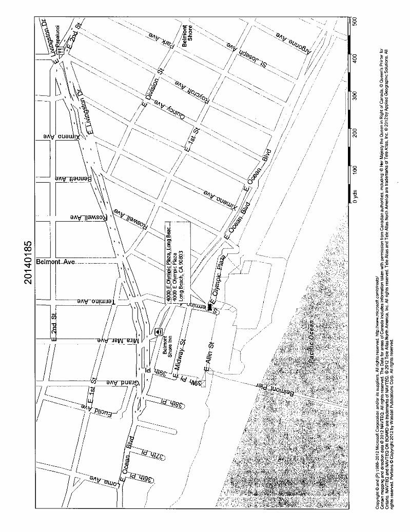
Olympic Pool Revitalization project in the City of Long Beach, California. The locations of the
existing buildings and our exploration borings are shown on Figure 1, Plot Plan. The results of our
current field explorations and laboratory tests are presented in Appendix A with the results of cone
penetration test (CPT) soundings and soil corrosivity testing presented in Appendices B and C,
respectively.
We previously performed a foundation investigation for the subject site and existing development
and submitted the results in a report dated August 15, 1966 (the report was issued under the name
of a MACTEC legacy company, LeRoy Crandall & Associates, Job No. A-66102). A copy of our
prior report is presented in Appendix D. The locations of our previous exploration borings are
shown on Figure 1. We have reviewed and accept the field and laboratory test data presented in
that report. However, with advances in knowledge of the behavior of soils since the report was
issued, many of the recommendations contained in the report are no longer considered to be
applicable.
This investigation was authorized to perform subsurface explorations, laboratory testing, and
geologic and engineering analyses to assess the geologic-seismic hazards that might affect the site.
We were also to provide preliminary geotechnical recommendations for use in evaluating the
existing development and to provide information for use in planning and preliminary design for
revitalization of the existing development or for replacement development. Our services were to
consist of the following main tasks:
• Review of prior data at the site that has been provided to us.
• Subsurface explorations to determine the nature and stratigraphy of the subsurface soils, and to obtain undisturbed and bulk samples for laboratory observation and testing.
• A geologic-seismic hazards evaluation including an evaluation of liquefaction, slope instability and surface rupture due to faulting or lateral spreading.
• Laboratory testing of soil samples for determination of the static physical soil properties.

Proposed Belmont Plaza Olympic Pool Revitalization Project April 15, 2009 MACTEC Engineering and Consulting, Inc., Project 4953-09-0301
2
• Corrosion studies to determine the presence of potentially corrosive soils.
• Engineering evaluation of the geotechnical data to develop preliminary recommendations for use in planning and preliminary design of the proposed revitalization or for a replacement development.
Our investigation was not intended to be sufficient to provide final geotechnical design
recommendations for use in design of structures at the site. A comprehensive investigation should
be performed to develop final recommendations once the structural features of the future work
have been established. Depending on the features of the future work, additional field and laboratory
testing may or may not be required.
Our recommendations are based on the results of our current and previous field explorations,
laboratory tests, and appropriate engineering analyses. The results of the current field explorations
and laboratory tests, which form the basis of our recommendations, are presented in Appendices A,
B, and C.

Proposed Belmont Plaza Olympic Pool Revitalization Project April 15, 2009 MACTEC Engineering and Consulting, Inc., Project 4953-09-0301
3
2.0 PROJECT CONSIDERATIONS
The Belmont Plaza Pool facility site is bounded on the north by East Olympic Plaza, Termino
Avenue (and its extension) on the west, Bennett Avenue on the east, and the beach (Pacific Ocean)
on the south. The northern (landward side) portion of the site is occupied by a park; the park is not
a part of the project. The site grades were raised by several feet for the existing development by
the placement of fill. There is a retaining wall up to 3 feet in height between the walk surrounding
the facility and the beach.
The existing building complex is roughly 440 feet by 220 feet in plan. Based on plans provided to
us, the existing building is supported on timber piles with tip diameters of at least 8 inches and
minimum lengths of 32 feet. The plans show the pile caps at various elevations. The pool walls and
diving towers are believed to be supported on shallow foundations. The structural features and
details are being evaluated by Miyamoto International, Inc. (2009).
It is proposed to evaluate the existing structure and foundations of the existing Belmont Plaza Pool
and to develop plans and recommendations for revitalization or replacement of the facility .

Proposed Belmont Plaza Olympic Pool Revitalization Project April 15, 2009 MACTEC Engineering and Consulting, Inc., Project 4953-09-0301
4
3.0 EXPLORATIONS AND TESTING
The soil conditions beneath the site were explored by drilling two borings to depths of about
76½ feet below the existing grade at the locations shown on Figure 1. Details of the current
explorations and the logs of the borings are presented in the Appendix A.
Laboratory tests were performed on selected samples obtained from the current borings to aid in
the classification of the soils and to determine the pertinent engineering properties of the
foundation soils. The following tests were performed:
• Moisture content and dry density determinations. • Direct shear. • Consolidation. • Sieve analyses. • Atterberg limits.
All testing was done in general accordance with applicable ASTM specifications. Details of the
laboratory testing program and test results are presented in the Appendix A.
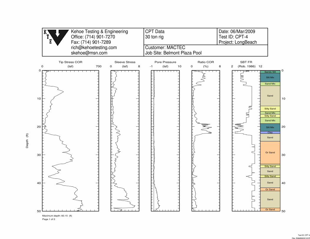
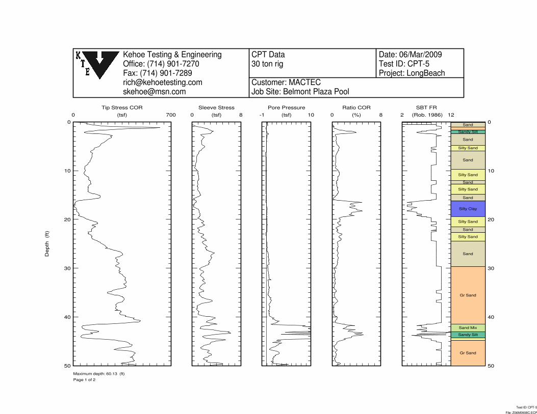
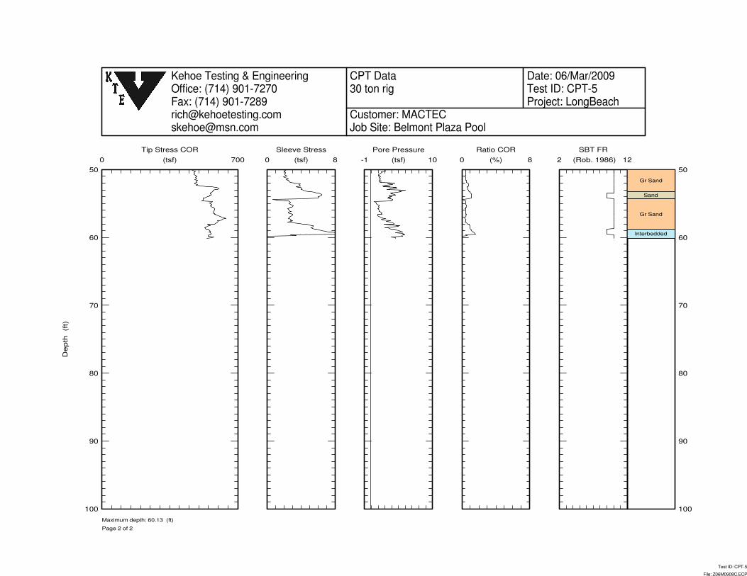
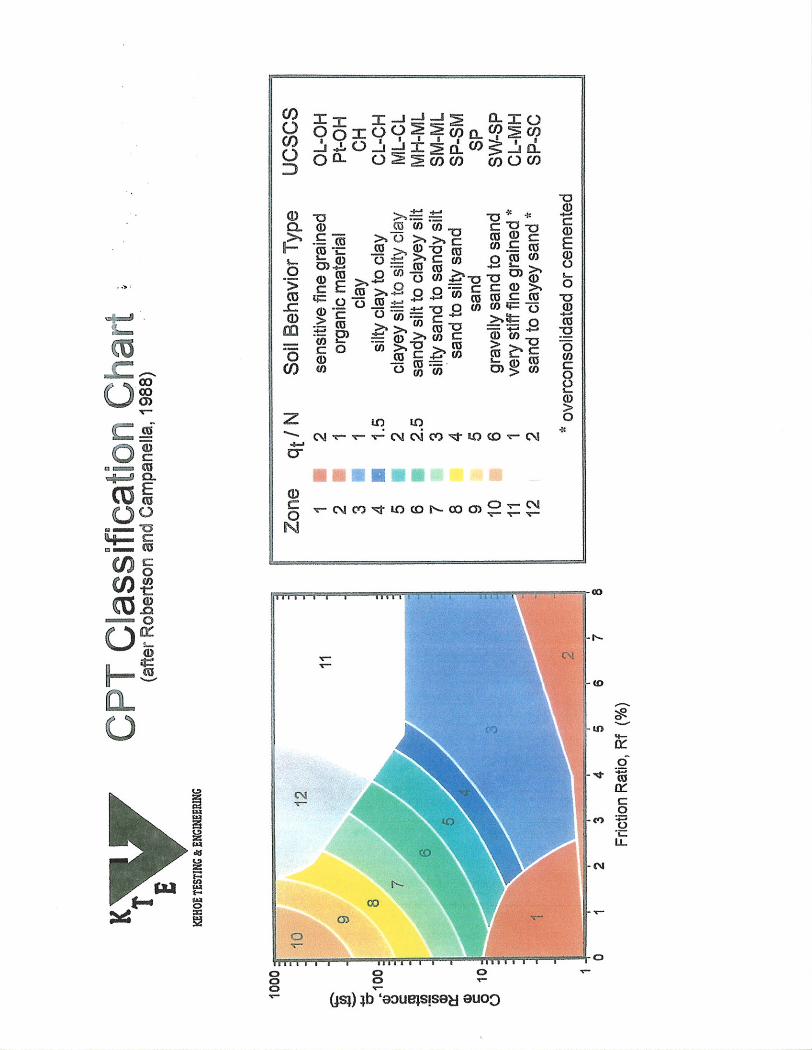
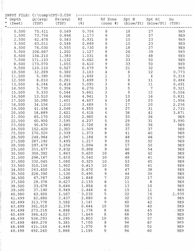
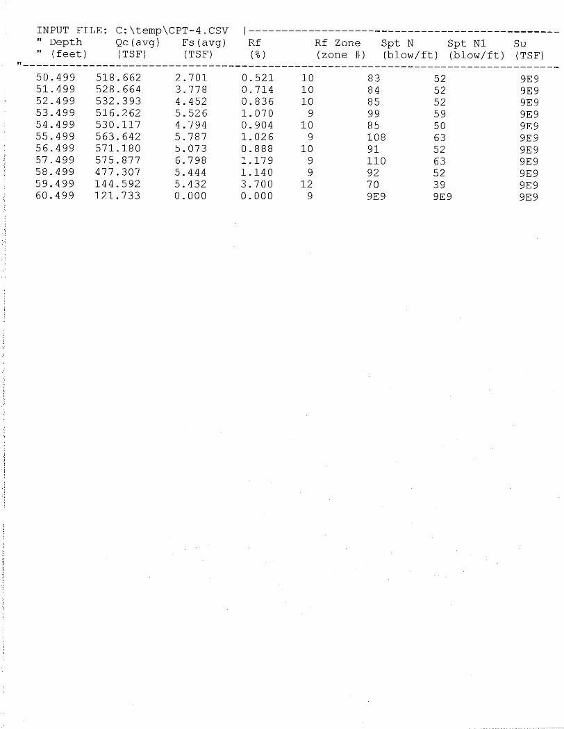
To supplement the data from the borings and laboratory tests, we retained Kehoe Testing &
Engineering (Kehoe) to perform Cone Penetration Test (CPT) soundings. The soundings were
performed at five locations selected by us to depths of approximately 60 feet each. Two of the
soundings were performed near the borings to provide correlation data. Shear wave measurements
were performed in one of the soundings (CPT-3). The results of Kehoe’s testing are presented in
Appendix B.
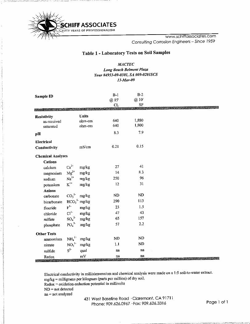
Soil Corrosivity tests were performed on two samples of the upper on-site soils by Schiff
Associates (Schiff). The results of the soil corrosivity study are presented in Appendix C.
Data were also available from our previous investigation for the subject site (our Job No.
A-66102). Our report for the previous investigation, including details of the prior explorations and
results of laboratory testing, is presented in Appendix D.

Proposed Belmont Plaza Olympic Pool Revitalization Project April 15, 2009 MACTEC Engineering and Consulting, Inc., Project 4953-09-0301
5
4.0 GEOLOGY
The site is located in the northern portion of the Peninsular Ranges geomorphic province. This
province extends northwesterly from Baja California into the Los Angeles Basin and westerly into
the offshore area, including Santa Catalina, Santa Barbara, San Clemente and San Nicolas islands.
The northern boundary of the province is the Transverse Ranges along the Malibu Coast, Santa
Monica, Hollywood, Raymond, Sierra Madre, and Cucamonga faults. The eastern boundary of the
province is the Colorado Desert geomorphic province along the San Jacinto fault system. The
Peninsular Ranges province is characterized by northwest/southeast trending alignments of
mountains and hills and intervening basins, reflecting the influence of northwest trending major
faults and folds, such as the nearby Newport Inglewood fault zone, controlling the general geologic
structural fabric of the region.
Most of the site is underlain by artificial fill. Fill consisting of silty sand was encountered in one of
our borings. The composition of the fill may vary across the site. While correspondence in our files
indicates that there was intent to compact the fill, we have no records that the fill was actually
compacted.
The fill is underlain by beach and estuary deposits consisting of poorly graded sand with silty sand,
sandy silt, and silty clay. The general geology of the area is shown on Figure 2, Regional Geology.
Ground water was encountered in our borings (current and previous) at depths of 5 to 9 feet below
the existing grade (Elevation +½ to +4 feet).

Proposed Belmont Plaza Olympic Pool Revitalization Project April 15, 2009 MACTEC Engineering and Consulting, Inc., Project 4953-09-0301
6
5.0 LIMITED GEOLOGIC-SEISMIC HAZARDS EVALUATION
Based on the available geologic data, active or potentially active faults with the potential for
surface fault rupture are not known to be located beneath or projecting towards the site. The closest
active fault to the site is the Newport Inglewood fault zone located approximately 1.5 miles to the
northeast. The Palos Verdes fault is located approximately 7 miles to the southwest. The site is not
in an Alquist-Priolo Earthquake Fault Zone. In our opinion, the potential for surface rupture at the
site due to fault plane displacement propagating to the ground surface during the design life of the
project is considered low.
Figure 3 shows the location of the site in relation to active faults and significant historic
earthquakes in the region. Although the site could be subjected to strong ground shaking in the
event of an earthquake, this hazard is common in Southern California and the effects of ground
shaking on structures can be mitigated by proper engineering design and construction in
conformance with current building codes and engineering practices.
The site is along the coastline and is susceptible to damage from a tsunami. Government agencies
are currently upgrading the region’s tsunami preparedness, warning, and evacuation systems. The
site is in a FEMA Special Flood Hazard Area subject to inundation by the 1% annual chance flood.
According to the City of Long Beach Safety Element of the General Plan, the site is not located
downslope of any large bodies of water that could adversely affect the site in the event of
earthquake-induced dam failures or seiches (wave oscillations in an enclosed or semi-enclosed
body of water).
The site is located between the Seal Beach and Wilmington oil fields. There are no known oil wells
on the site. The site is along the margins of the area impacted by ground subsidence due to oil
extraction in the Wilmington oil field. Water injection was begun in 1958 to repressurize the oil
field and the area has been stabilized.
The site is relatively level and the absence of nearby slopes precludes any slope stability hazards.
The site is not in a state of California Earthquake-Induced Landslide Hazard Zone (California
Division of Mines and Geology, CDMG, 1999).

Proposed Belmont Plaza Olympic Pool Revitalization Project April 15, 2009 MACTEC Engineering and Consulting, Inc., Project 4953-09-0301
7
6.0 LIQUEFACTION EVALUATION
Liquefaction potential is greatest where the ground water level is shallow, and submerged loose,
fine sands occur within a depth of about 15 meters (50 feet) or less. Liquefaction potential
decreases as grain size and clay and gravel content increase. As ground acceleration and shaking
duration increase during an earthquake, liquefaction potential increases. The site is within a state of
California designated Liquefaction Hazard Zone (CDMG, 1999).
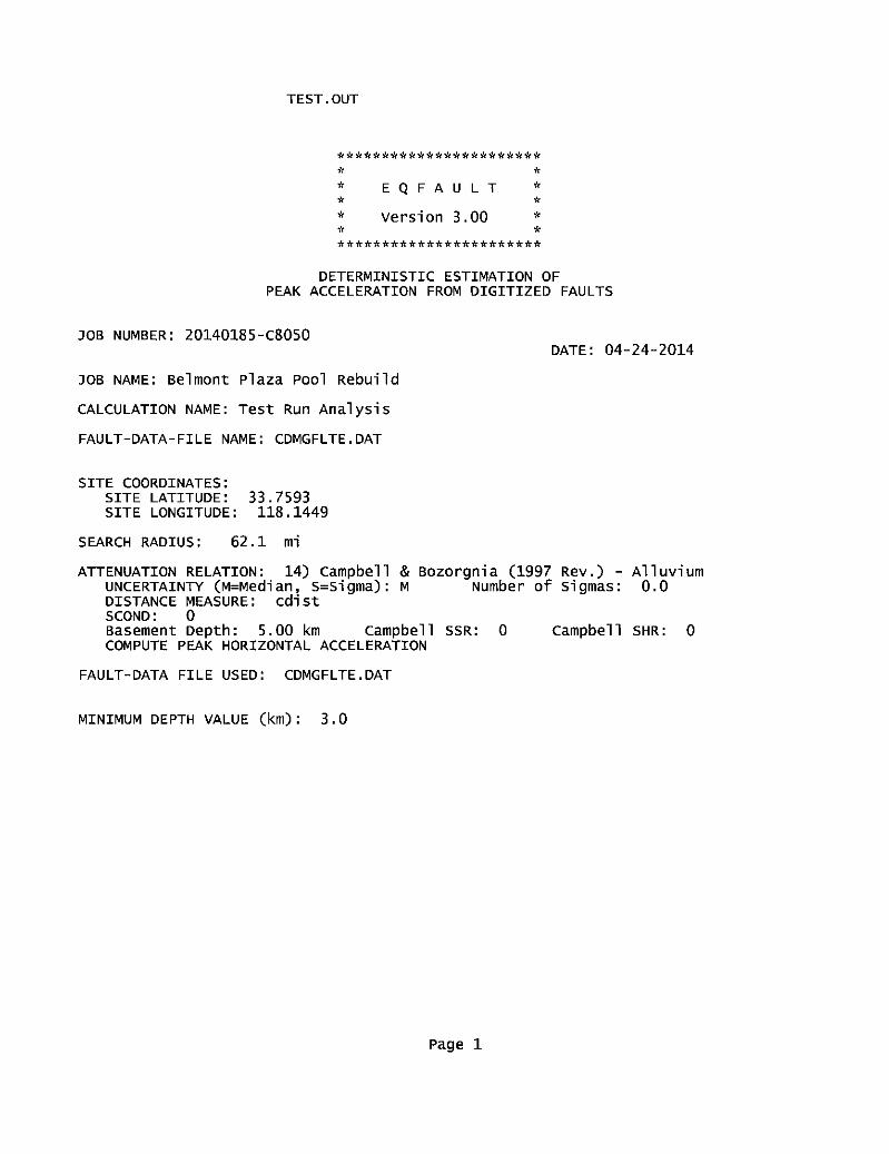
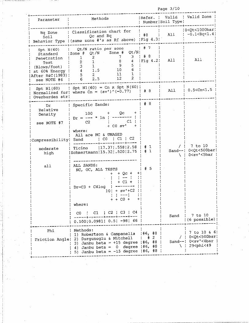
To evaluate the site-specific liquefaction potential, we computed the peak ground acceleration
(PGA) for the maximum credible earthquake ground motion with a 2% probability of being
exceeded in 50 years using EZ-FRISK, Version 7.32. This ground motion, which has a return
period of 2,475 years, was adjusted to be compatible with a Magnitude 7.5 earthquake. The next
generation ground motion attenuation relationships (NGA) of Abrahamson & Silva (2008), Boore
& Atkinson (2008), Campbell & Bozorgnia (2008) and Chiou & Young, (2008) were used, with
equal weight, in the analysis. Based on the shear wave velocity measurements in CPT-3, a shear
wave velocity of 267 meters per second was used for the upper 30 meters. The depth which the
shear wave velocity is at least 1,000 meters per second was assumed to be 2 kilometers while the
depth at which the velocity is at least 2,500 meters per second was assumed to be 4 kilometers. The
details of the CPT soundings and shear wave velocity measurements are presented in Appendix B.
We used a PGA for our liquefaction analyses that is two-thirds of the Magnitude-7.5 compatible
PGA for equivalence with the design level earthquake as defined in the 2007 California Building
Code and ASCE 7-05, and as referenced in California Geological Survey Note 48 dated October
2007. The Magnitude 7.5-compatible PGA computed in this manner for the subject site is 0.40g.
(The Magnitude-7.5 compatible PGA is not the same as the one used in the evaluation of
structures. This latter PGA is 0.49g).
The liquefaction potential of the soils underlying the site was evaluated using the Magnitude-7.5
compatible PGA, as described above and the results of our current explorations at the project site.
The ground-water level for our liquefaction analysis was assumed to be 7 feet below the existing
grade based on our measurements of the ground water level; the historical high ground-water level
has not been established for the site. The liquefaction potential was computed according to
procedures described in Youd et al. (2001).

Proposed Belmont Plaza Olympic Pool Revitalization Project April 15, 2009 MACTEC Engineering and Consulting, Inc., Project 4953-09-0301
8
Seismically-induced settlement is often caused by loose to medium-dense granular soils densified
during ground shaking. Dry and partially saturated soils as well as saturated granular soils are
subject to seismically-induced settlement. The medium dense granular soils encountered in our
exploratory borings are considered to be susceptible to liquefaction and seismically-induced
settlement. We evaluated the seismically-induced settlement based on the procedures outlined by
Tokimatsu and Seed (1987) and Ishihara and Yoshimine (1992). We estimate the seismically-
induced settlement to be about ¾ to 2¾ inches.
Some, but not all, liquefiable soils are susceptible to lateral spreading. Methods to calculate the
extent and magnitude of lateral spreading are few and only provide a rough order of magnitude
estimates of the amount of lateral spreading. Assuming that the soils between the site and the
Pacific Ocean are similar to those beneath the site, several feet of lateral spreading towards the
Pacific Ocean could occur in the event of design earthquake ground motions. The movement of the
soils due to lateral spreading would not be expected to be uniform. Therefore, differential lateral
spreading should be expected in the building area. We evaluated the lateral spreading potential
based on the procedures outlined by Youd et al (2002).

Proposed Belmont Plaza Olympic Pool Revitalization Project April 15, 2009 MACTEC Engineering and Consulting, Inc., Project 4953-09-0301
9
7.0 RECOMMENDATIONS
7.1 GENERAL
The existing Belmont Plaza buildings, especially the pool building, are being considered for
structural rehabilitation or replacement. The plans for the existing buildings indicate that they are
supported on timber piles. While the foundation recommendations presented in our 1966 report
remain applicable for static loading, the upper soils are subject to liquefaction in the event of
design earthquake level ground motion at the site. Liquefaction of the on-site soils would result in
significant reductions in the capacities of the existing foundations. In the event of strong ground
motion at the site, settlement and damage to the existing structures’ foundations and structural
elements should be anticipated.
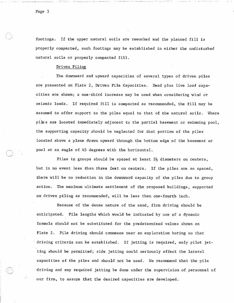
If renovation of the existing buildings is to be performed, piling is expected to be the most feasible
means of replacing or strengthening the foundations. Because of expected caving in the granular
soils below the relatively shallow ground water level beneath the site, the installation of
conventional drilled cast-in-place concrete piling would be difficult. Since the installation of new
piling would for the most part be performed within the existing structures, micro-piles or auger-cast
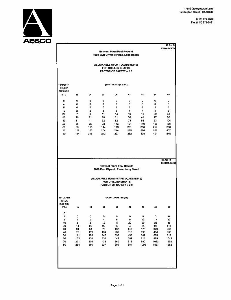
piles are recommend. For preliminary planning purposes, 10-inch-diameter mini-piles or 24-inch-
diameter auger cast piles should extend approximately 50 feet below the existing grade to develop
a downward capacity of 160 kips (sufficient capacity to replace two of the existing timber piles). In
addition to replacing and/or strengthening the foundations, some means of mitigating the potential
lateral spreading should be used. This mitigation would most likely consist of ground improvement
between the existing buildings and the Pacific Ocean; the improvements should be constructed as
close to the buildings as possible.
If the buildings are to be replaced, the liquefaction induced settlement and lateral spreading should
be mitigated by ground improvement of the site. The replacement buildings could then be
supported on shallow foundations, most likely spread footings.

Proposed Belmont Plaza Olympic Pool Revitalization Project April 15, 2009 MACTEC Engineering and Consulting, Inc., Project 4953-09-0301
10
7.2 FOUNDATIONS
Existing Timber Piles
The existing building is reportedly supported on timber piles. The tip diameter of thee piles was to
be 8 inches in diameter and the piles were to be a minimum of 32 feet long. Based on our previous
report (1966) for the site, these piles have an allowable downward design capacity of 80 kips. As
was usual at the time the analyses were performed, this capacity does not consider liquefaction.
(The Niigata and Alaska earthquakes of 1964 were the start of liquefaction becoming a concern.
The early versions of the current procedures to evaluate liquefaction were not published for use
until the 1980s and only nominal peak ground accelerations were usually used in the analyses until
the 1994 Northridge Earthquake.)
In the event of liquefaction affecting the upper 20 feet soils, as could potentially occur based on our
current analyses, the existing piles would be overloaded with the ultimate downward axial capacity
of the piles being temporarily less than the structural and downdrag forces imposed on the piles.
The extent of the consequences are this is difficult to project since to a large degree they are
influenced by the structure and will be locally variable. However, readily perceptible settlement of
the structure, probably on the order of several inches, is expected with probable permanent damage
to the timber piles and the structure. There would also be a loss of lateral capacity of the piles
probably resulting in some lateral movement of the building columns. Slabs supported on grade
supported will settle and voids may develop beneath the slabs.
New Foundations
Provided that ground improvement is performed at the site in accordance with the
recommendations in the Grading section of this report, the replacement buildings may be supported
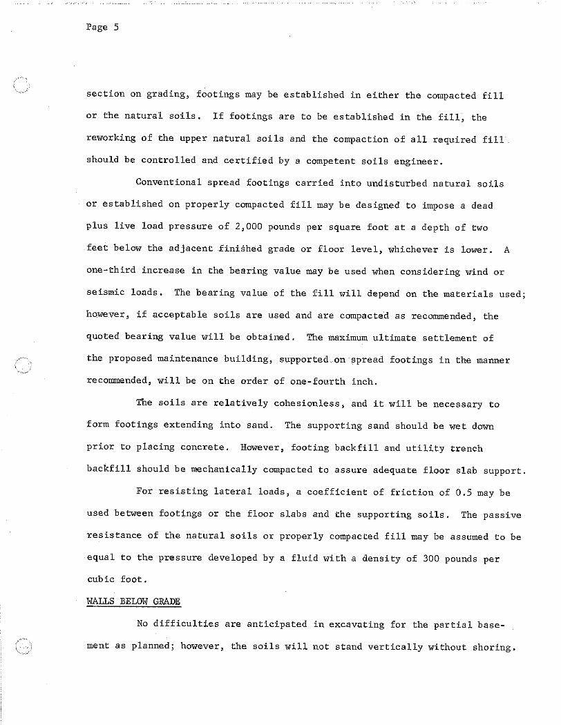
on spread footings. Spread footings carried at least 1 foot into properly compacted fill and at least 2
feet below the lowest adjacent grade or floor level can be designed to impose a net dead-plus-live
load pressure of 3,000 pounds per square foot. The excavations should be deepened as necessary
to extend into satisfactory soils. A one-third increase can be used for wind or seismic loads. The
recommended bearing value is a net value, and the weight of concrete in the footings can be taken
as 50 pounds per cubic foot; the weight of soil backfill can be neglected when determining the
downward loads.

Proposed Belmont Plaza Olympic Pool Revitalization Project April 15, 2009 MACTEC Engineering and Consulting, Inc., Project 4953-09-0301
11
Lateral loads can be resisted by soil friction and by the passive resistance of the soils. A coefficient
of friction of 0.4 may be used between the footings and the floor slab and the supporting soils. The
passive resistance of natural soils or properly compacted fill soils can be assumed to be equal to the
pressure developed by a fluid with a density of 250 pounds per cubic foot. A one-third increase in
the passive value can be used for wind or seismic loads. The frictional resistance and the passive
resistance of the soils can be combined without reduction in determining the total lateral resistance.
7.3 SITE COEFFICIENT AND SEISMIC ZONATION
We have determined the seismic parameters in accordance with the Section 1613A of the 2007
edition of the California Building Code (2007 CBC) and Section 11.4 of ASCE 7-05 Standard
(ASCE, 2005) using the United States Geological Survey (USGS, 2007) program, Earthquake
Ground Motion Parameters, Version 5.0.8. The site location used was Latitude 33.7581° and
Longitude -118.1456° with a Site Class “D.” If the proposed buildings are to be designed using the
provisions of the 2007 CBC, the seismic site coefficients may be taken as presented below:
Site Coefficient Value SS (0.2 second period, Site Class B) 1.74g S1 (1.0 second period, Site Class B) 0.67g Site Class D Fa 1.00 Fv 1.50 SMS = FaSS (0.2 second period, Site Class D) 1.74g SM1 = FvS1 (1.0 second period, Site Class D) 1.00g SDS = 2/3 x SMS (0.2 second period, Site Class D) 1.16g SD1 = 2/3 x SM1 (1.0 second period, Site Class D) 0.67g
By MKT 4/2/09 Chkd By LT 4/5/09
7.4 FLOOR SLAB SUPPORT
For pile supported buildings, the floor slabs should be structurally supported. If the subgrade is
prepared as recommended in a following section on grading and some distress in the on-grade
concrete walks and slabs as a result of liquefaction in the event of strong ground motion is
acceptable, the concrete walks and slabs adjacent to the buildings may be supported on grade.
If the upper soils are improved so that the buildings can be supported on spread footings, the floor
slabs may be supported on grade on the improved soils. Construction activities and exposure to the
environment can cause deterioration of the prepared subgrade. Therefore, we recommend that our

Proposed Belmont Plaza Olympic Pool Revitalization Project April 15, 2009 MACTEC Engineering and Consulting, Inc., Project 4953-09-0301
12
field representative observe the condition of the final subgrade soils immediately prior to slab-on-
grade construction, and, if necessary, perform further density and moisture content tests to
determine the suitability of the final prepared subgrade.
In areas where vinyl or other moisture-sensitive floor covering is planned, we recommend that the
floor slab in those areas be underlain by a vapor retarder/barrier consisting of a vapor-retarding
membrane. If the interior of the structure directly above the slab-on-grade is a humidity controlled
area, then the same recommendations apply. The membrane should conform to the requirements of
ASTM E 1745, “ Standard Specifications for Water Vapor Retarders in Contact with Soil or
Granular Fill under Concrete Slabs.” The installation of the membrane applies to both the
structurally supported floor slabs and slabs supported on grade.
In addition, measures will be required to prevent slab curling due to uneven curing between the top
and the bottom of the slab. These measures should consist of one or more of the following:
• Reduced joint spacing
• A low shrinkage concrete mix design such as a low water/cement ratio mix or water-reducing admixtures
• Use of a 2-inch thick “blotter” layer
If a blotter layer is used, it should consist of trimmable, free-draining granular fill between the
membrane and the slab. The blotter layer fill should have a Sand Equivalent of 30. The blotter layer
should be placed with a moisture content of less than 5% percent. Note that if a blotter layer is
used, then the layer should not be allowed to become wet (due to rain, wet-curing, wet-grinding or
cutting, and cleaning where water enters prior to slab placement or after slab placement through
openings such as column block-outs). Also, the blotter layer should be cut off from sources of
water (for instance, the blotter layer should not be continuous to the exterior of the building).
Care should be taken to prevent any tears or discontinuities in the membrane. The membrane
should be inspected prior to placement of the slab or installation of a blotter layer and any holes or
discontinuities (e.g., around penetrations) properly sealed.

Proposed Belmont Plaza Olympic Pool Revitalization Project April 15, 2009 MACTEC Engineering and Consulting, Inc., Project 4953-09-0301
13
Where vinyl or other moisture sensitive floor covering or storage of moisture sensitive materials is
not planned, the floor slab and other concrete slabs may be supported directly on the final prepared
subgrade.
7.5 RETAINING WALLS AND WALLS BELOW GRADE
Lateral Earth Pressure
For design of cantilevered retaining walls, where the surface of the backfill is level, it may be
assumed that drained soils will exert a lateral pressure (active earth pressure) equal to that
developed by a fluid with a density of 30 pounds per cubic foot. In addition to the recommended
earth pressure, the walls should be designed to resist any applicable surcharges due to storage or
traffic loads. If the soils are not drained, they should also resist hydrostatic pressures.
For the design of braced basement walls, it may be assumed that drained soils will exert a lateral
pressure (at-rest earth pressure) equal to that developed by a fluid with a density of 52 pounds per
cubic foot. In addition to the recommended earth pressure, the walls should be designed to resist
any applicable surcharges due to foundation, storage, or traffic loads. If the soils are not drained,
they should also resist hydrostatic pressures.
In addition to the recommended earth pressure, retaining walls adjacent to areas subject to
vehicular traffic should be designed to resist a uniform lateral pressure of 100 pounds per square
foot, acting as a result of an assumed 300 pounds per square foot surcharge behind the walls due to
normal vehicular traffic. If the traffic is kept back at least 10 feet from the walls, the traffic
surcharge may be neglected.
Seismic Lateral Earth Pressure
In addition to the above-mentioned lateral earth pressures, basement walls with more than 6 feet of
unbalanced earth (where the difference in height of retained soil from one side of the basement to
the other is greater than 6 feet) and cantilever retaining walls greater than 12 feet in height should
be designed to support a seismic active pressure. The seismic active pressure for use in design
should be applied uniformly to the back of the wall and should taken as being 5H pounds per
square foot, where H is the height of the retained soils in feet or the difference in height of the
retained soils between the opposing basement walls.

Proposed Belmont Plaza Olympic Pool Revitalization Project April 15, 2009 MACTEC Engineering and Consulting, Inc., Project 4953-09-0301
14
Drainage
Walls, or at least the portions of walls, that extend below Elevation +8 feet should be designed to
resist hydrostatic pressure in addition to the lateral earth, seismic, traffic, and other surcharge
pressures. The portions of walls not designed to resist hydrostatic pressures should be provided
with a drainage system. However, walls that are provided with a full height drainage system and
use weepholes at the base of the wall (such as retaining walls that are separate from the buildings)
for removal of the water do not need to be designed to resist hydrostatic pressure even if they
extend below Elevation +8. For design, the hydrostatic pressure may be taken as being 50 pounds
per cubic foot (this pressure considers buoyancy of the soils and the unit weight of salt water).
Walls below grade that are not designed to resist hydrostatic pressures should be provided with a
drainage system placed behind the walls below grade to help dissipate the hydrostatic forces that
may develop behind the walls. The drainage system may consist of a 4-inch-diameter perforated
pipe placed with the perforations down and surrounded by at least 4 inches of granular filter gravel.
The pipe should be sloped at least 2 inches in 100 feet. The granular filter material should be
separated from the adjacent soils by a filter fabric. The perforated pipes should be placed at the
bases of the walls below grade. In addition, a 1-foot wide zone of granular filter material, or
continuous Miradrain collector panels, should be placed behind each wall. The strip of granular
filter material or the Miradrain (Miradrain 6000 or equivalent) panels should extend down to the
drainage system, and should be terminated at 2 feet below the ground surface.
The installed drainage system should be observed by personnel from our firm prior to being
backfilled. Inspection of the drainage system may also be required by the reviewing governmental
agencies.
It should be realized that a permit from the State of California Regional Water Quality Control
Board would have to be obtained to discharge the water from the drainage system into the storm
drain. To obtain such a permit, chemical tests will have to be performed on water samples obtained
at the site to verify that chemicals or pollutants within the water do not exceed the allowable limits
for discharging into the storm drain.

Proposed Belmont Plaza Olympic Pool Revitalization Project April 15, 2009 MACTEC Engineering and Consulting, Inc., Project 4953-09-0301
15
7.6 GRADING
Site Improvement
If the upper potentially liquefiable soils are sufficiently improved, the potential liquefaction hazard
at the site would be mitigated and the replacement buildings could be supported on spread footings,
unless other considerations require the use of piling. If the existing buildings and/or pool are
proposed to remain, ground improvement probably will not be a feasible alternative to piling due to
possibility of damaging the buildings and/or pool.
We expect that a ground improvement procedure such as stone columns or Vibro-Replacement
would provide the best outcome for the project site. These procedures consist of densifying the on-
site soils and the addition coarse grained materials. The presence of silts and clays in the upper
soils excludes the possibility of using techniques that would just densify the on-site soils. The
ground improvement should extend at least 25 feet below the existing surrounding grade to
approximately Elevation -18 feet (18 feet below sea level). The ground improvement procedure is
performed by a specialty contractor and such a contractor should be consulted early on in the
planning process to aid in determining if proceeding with ground improvement alternative is
economically desirable. We would be pleased to develop recommendations for planning and
verification of sufficient improvement if it is decided to proceed with ground improvement.
After the on-site soils are improved, the surface of the ground is expect to be lower and the upper
materials will be disturbed. The disturbed materials should be excavated as recommended in the
following section on Site Preparation and Compaction.
Site Preparation and Compaction
To provide support for at-grade concrete walks and slabs adjacent to the new buildings, all the
existing uncertified fill (those fills for which a record of compaction during placement is
unavailable) should be excavated. To our knowledge, the existing fill soils at the site were not
observed and tested during placement. Further excavation should be performed to remove disturbed
natural soils within the construction area and for at least 2 feet beyond any proposed paving and
5 feet beyond any proposed footings in plan. Where there is insufficient room for the recommended
overexcavation, we can provide case specific recommendations. The excavated soils should be
replaced as properly compacted fill. All planned additional fill should be properly compacted.
Proposed Belmont Plaza Olympic Pool Revitalization Project April 15, 2009 MACTEC Engineering and Consulting, Inc., Project 4953-09-0301
16
Where excavations are deeper than about 4 feet, the sides of the excavations should be sloped back
at 1:1 (horizontal to vertical) or shored for safety. Adjacent to an existing building, the excavations
should not extend below a plane drawn downward at 1½: (horizontal to vertical) from the bottoms
of the exterior footings (pile caps and/or grade beams) of the existing buildings. If the existing pool
is to remain, the excavation should not extend below 1½:1 1 (horizontal to vertical) plane
extending downward from the top edge of the pool.
All applicable requirements of the 2009 State of California Construction and General Industry
Safety Orders, the Occupational Safety and Health Act of 1970, and the Construction Safety Act
should be met.
After excavating the upper soils as recommended, the exposed natural soils should be carefully
observed for the removal of all unsuitable deposits. Next, the exposed soils should be rolled with
heavy compaction equipment. The upper 6 inches of exposed soils should be compacted to at least
90% of the maximum density obtainable by the ASTM Designation D1557-07 method of
compaction. For soils with less than 5% of the particles by weight passing the No. 200 sieve, the
soils should be compacted to at least 95%.
After compacting the exposed soils, all required fill should be placed in loose lifts not more than
8 inches thick and compacted to at least 90% (95% if less than 5% of the particles pass the No. 200
sieve). The moisture content of the on-site granular soils at the time of compaction should vary
from zero to no more than 4% above optimum moisture content. The moisture content of any on-
site cohesive soils at the time of compaction should be brought to about 4% over optimum moisture
content.
Material for Fill
The on-site soils, less any debris or organic matter, may be used in required fills. The on-site
clayey soils should not be placed with 2 feet of proposed floor slabs, pool decks, or other portland
cement concrete paved areas. Any required imported material should consist of relatively non-
expansive soils with an Expansion Index of less than 35. The imported materials should contain
sufficient fines (binder material) so as to be relatively impermeable and result in a stable subgrade
Proposed Belmont Plaza Olympic Pool Revitalization Project April 15, 2009 MACTEC Engineering and Consulting, Inc., Project 4953-09-0301
17
when compacted. All proposed import materials should be approved by our personnel prior to
being placed at the site.
7.7 GEOTECHNICAL OBSERVATION
The reworking of the upper soils and the compaction of all required fill should be observed and
tested during placement by a representative of our firm. This representative should perform at least
the following duties:
• Observe the clearing and grubbing operations for proper removal of all unsuitable materials.
• Observe ground improvement procedures if they are used.
• Observe the exposed subgrade in areas to receive fill and in areas where excavation has resulted in the desired finished subgrade. The representative should also observe proofrolling and delineation of areas requiring overexcavation.
• Evaluate the suitability of on-site and import soils for fill placement; collect and submit soil samples for required or recommended laboratory testing where necessary.
• Observe the fill and backfill for uniformity during placement.
• Test backfill for field density and compaction to determine the percentage of compaction achieved during backfill placement.
• Observe and probe foundation materials to confirm that suitable bearing materials are present at the design foundation depths.
• Observe the installation of piling and any testing of the piling that is required.
The governmental agencies having jurisdiction over the project should be notified prior to
commencement of grading so that the necessary grading permits can be obtained and arrangements
can be made for required inspection(s). The contractor should be familiar with the inspection
requirements of the reviewing agencies.

Proposed Belmont Plaza Olympic Pool Revitalization Project April 15, 2009 MACTEC Engineering and Consulting, Inc., Project 4953-09-0301
18
8.0 GENERAL LIMITATIONS AND BASIS FOR RECOMMENDATIONS
Our professional services have been performed using that degree of care and skill ordinarily
exercised, under similar circumstances, by reputable geotechnical consultants practicing in this or
similar localities. No other warranty, expressed or implied, is made as to the professional advice
included in this report. This report has been prepared for MDM Architects, LLP, their client, the
City of Long Beach, and their design consultants to be used solely in the evaluation, planning and
design of the proposed Belmont Plaza Olympic Pool Revitalization Project. The report has not been
prepared for use by other parties, and may not contain sufficient information for purpose of other
parties or other uses.
The recommendations provided in this report are based upon our understanding of the described
project information and on our interpretation of the data collected during our current and previous
subsurface explorations. We have made our recommendations based upon experience with similar
subsurface conditions under similar loading conditions. The recommendations apply to the specific
project discussed in this report; therefore, any change in the structure configuration, loads, location,
or the site grades should be provided to us so that we can review our conclusions and
recommendations and make any necessary modifications.
The recommendations provided in this report are also based upon the assumption that the necessary
geotechnical observations and testing during construction will be performed by representatives of
our firm. The field observation services are considered a continuation of the geotechnical
investigation and essential to verify that the actual soil conditions are as expected. This also
provides for the procedure whereby the client can be advised of unexpected or changed conditions
that would require modifications of our original recommendations. If another firm is retained for
the geotechnical observation services, our professional responsibility and liability would be limited
to the extent that we would not be the geotechnical engineer of record.

Proposed Belmont Plaza Olympic Pool Revitalization Project April 15, 2009 MACTEC Engineering and Consulting, Inc., Project 4953-09-0301
19
9.0 REFERENCES
Abrahamson, N. A. and Silva, W. J., 2008. Summary of the Abrahamson & Silva NGA Ground Motion Relations, Earthquake Spectra, V. 24, No. 1.
Boore, D. M., and Atkinson, G. M., 2008, Ground-motion Prediction Equations for the Average Horizontal Component of PGA, PGV, and 5%-damped PSA at Spectral Periods between 0.01s and 10.0s, Earthquake Spectra, V. 24, No. 1.
California Division of Mines and Geology, 1997, “Guidelines for Evaluating and Mitigating Seismic Hazards in California,” Special Publication 117.
California Division of Mines and Geology, 1998, “Seismic Hazard Zone Report for the Long Beach 7.5-Minute Quadrangle, Los Angeles County, California,” Seismic Hazard Zone Report 028, revised 2006.
California Division of Mines and Geology, 1999, “State of California Seismic Hazard Zones, Long Beach Quadrangle, Official Map,” released March 25, 1999.
Campbell, K. W., and Bozorgnia, Y., 2008, Ground Motion Model for the Geometric Mean Horizontal Component of PGA, PGV, PGD and 5% Damped Linear Elastic Response Spectra for Periods Ranging from 0.01s to 10.0s, Earthquake Spectra, V. 24, No. 1.
Chiou, B., and Youngs, R., 2008, A NGA Model for the Average Horizontal Component of Peak Ground Motion and Response Spectra, Earthquake Spectra, V. 24, No. 1.
LeRoy Crandall and Associates, 1966a, “Foundation Investigation, Proposed Belmont Plaza Beach Center, Long Beach, California,” Job No. A-66102, report dated August 15, 1966.
LeRoy Crandall and Associates, 1966b, “Compacted Fill Material, Proposed Belmont Plaza Beach Center, Allin Street and Termino Avenue, Long Beach, California,” Job No. A-66102, letter dated November 9, 1996.
LeRoy Crandall and Associates, 1967, “Support of Swimming Pool Walls and Diving Towers, Proposed Belmont Plaza Beach Center, Allin Street and Termino Avenue, Long Beach, California,” Project No. A-66102, letter dated February 13, 1967.
Miyamoto International, Inc., 2009, “Structural Evaluation of Belmont Plaza Beach Center Community and Locker Facilities, Long Beach, California,” report dated January 30, 2009, Original: MI0600198.00, Appendix B: MI0802027.00.
Risk Engineering, Inc., 2009, EZ-FRISK version 7.32.
Tokimatsu, K., and Seed, H. B., 1987, “Evaluation of Settlements in Sands due to Earthquake Shaking,” Journal of Geotechnical Engineering, ASCE, Vol. 113, No. 8, pp. 861-878.
U.S. Geological Survey, 2008, Earthquake Motion Parameters, Version 5.0.9.
Ishihara, K. and Yoshimine, M. 1992. “Evaluation of settlements in sand deposits following liquefaction during earthquakes.” Soils and Foundations. Vol. 32(1): 173-188.
Youd, T. L. et al, 2001, “Liquefaction Resistance of Soils: Summary Report from the 1996 NCEER and 1998 NCEER/NSF Workshops on Evaluation of Liquefaction Resistance of Soils,” Journal of Geotechnical and Geoenvironmental Engineering, ASCE, Vol. 127, No. 10, October, 2001.

Proposed Belmont Plaza Olympic Pool Revitalization Project April 15, 2009 MACTEC Engineering and Consulting, Inc., Project 4953-09-0301
20
Youd, T. Leslie, Hansen, Crobett M., and Bartlett, Steven F., “Revised Multi-linear Regression Equations for Prediction of Lateral Spread Displacement ,” Journal of Geotechnical and Geoenvironmental Engineering, ASCE , December 2002.
10.0

Proposed Belmont Plaza Olympic Pool Revitalization Project April 15, 2009 MACTEC Engineering and Consulting, Inc., Project 4953-09-0301
FIGURES

Base: California Geological Survey, 2003,Geologic Map of the Long Beach 30’x 60’Quadrangle, California, Map No. 5
JOB NO.:
DATE:
SCALE:
DRAWN BY:
CHECKED BY:
REVISIONS:
Figure 2 - Regional GeologyBelmont Plaza Olympic Pool Revitalization
Long Beach, California
03/30/2009
4953-09-0301
DGW
As shown
MACTEC ENGINEERING AND CONSULTING, INC.5628 E. Slauson Ave., Los Angeles, California 90040
(323) 889-5300, fax (323) 889-5398
SITE
PER

1857M 8+
1925M 6.3
1916M 6.0
1971M 6.6
1994M 6.7
1987M 5.9
1991M 5.8
1812M 6.9
1899M 7.0
1890M 7.0
1907M 6.0
1923M 6.3
1910M 6.0
1918M 6.8
1992M 6.4
1933M 6.4
1938M 5.5
1963M 5.1
1935M 5.1
1943M 5.3
2003M 5.4
1992M 5.4
1943M 5.3
1962M 5.0
1970M 5.2
1990M 5.4
1933M 5.4
1979M 5.2
1968M 5.3 1973
M 5.3
1941M 5.5
1978M 5.1
1981M 5.5
1988M 5.4
1941M 5.1
1952M 7.5
1952M 5.1
1997M 5.1
APPROXIMATE EPICENTRAL AREA OF EARTHQUAKE
YearM8+
YearM7+
YearM6+
YearM5+
Historic FaultDisplacement
Holocene FaultDisplacementWithout HistoricRecord
REFERENCES:
Jennings, C.W., 1994, “Fault Activity Map of California and Adjacent Areas with Locations and Ages ofRecent Volcanic Eruptions,” California Division of Mines and Geology, GDM-6.
Earthquake Catalogs: Richter, 1812-1905, National Oceanic and Atmospheric Administration,1906-1931; Caltech, 1932-2005.
o
24
20KM
Miles120
0 10
L Site
SITE
4953-05-04245-31-07as shown
PER
JOB NO.:
DATE:
SCALE:
DRAWN BY:
CHECKED BY:
REVISIONS:
Figure 3 - Regional Faults and SeismicityBelmont Plaza Olympic Pool Revitalization
Long Beach, California
03/30/2009
4953-09-0301
DGW
As shown
MACTEC ENGINEERING AND CONSULTING, INC.
5628 E. Slauson Ave., Los Angeles, California 90040
(323) 889-5300, fax (323) 889-5398
RM

Proposed Belmont Plaza Olympic Pool Revitalization Project April 15, 2009 MACTEC Engineering and Consulting, Inc., Project 4953-09-0301
APPENDIX A
CURRENT EXPLORATIONS AND LABORATORY TESTS

Proposed Belmont Plaza Olympic Pool Revitalization Project April 15, 2009 MACTEC Engineering and Consulting, Inc., Project 4953-09-0301
A-1
APPENDIX A
CURRENT EXPLORATIONS AND LABORATORY TESTS EXPLORATIONS The soil conditions beneath the site were explored by drilling two borings. In addition, data were
available from our prior investigation at the site (our Job No. A-66102). The locations of our
current and prior borings are shown on Figure 1. The current borings were drilled to depths of
about 76½ feet below the existing grade using 5-inch-diameter rotary-wash-type drilling
equipment. Drilling mud was used to prevent caving. The mud was removed following completion
of the drilling to permit future measurements of the water level.
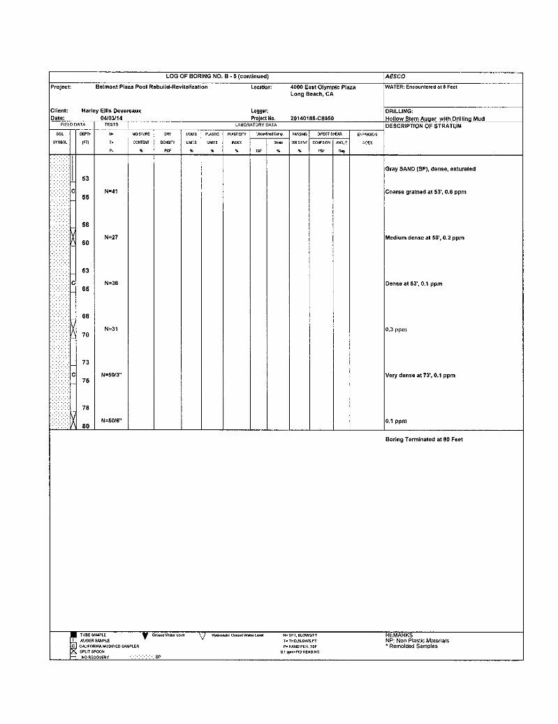
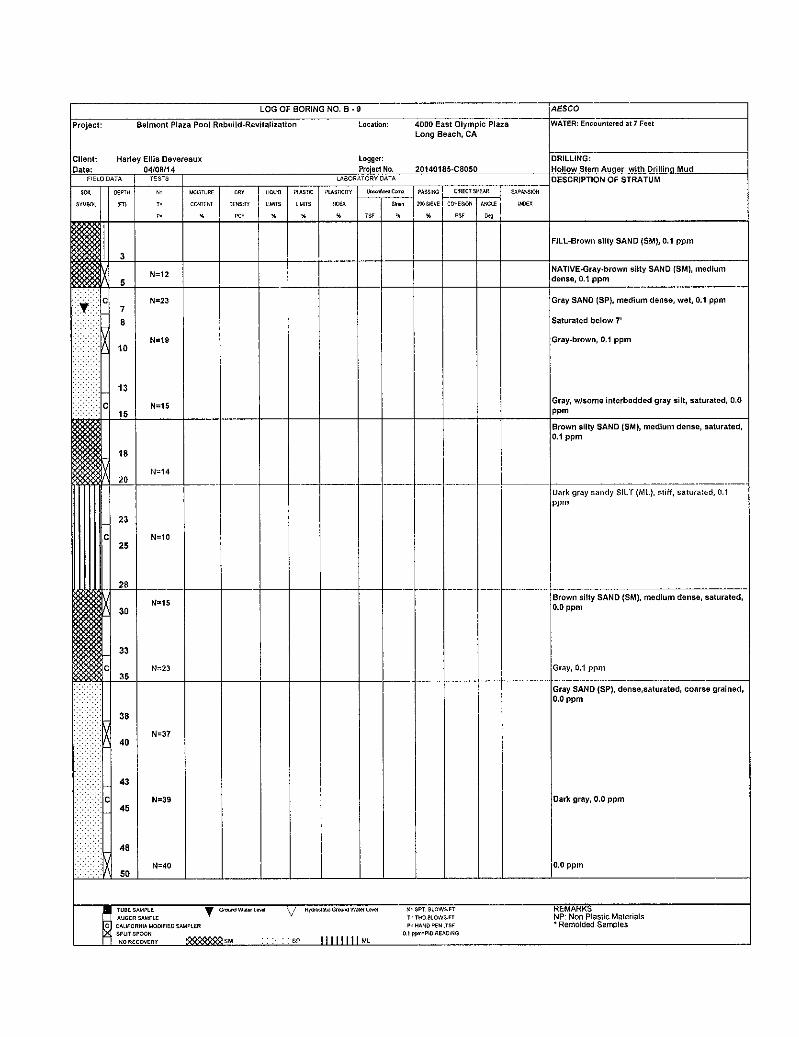
The soils encountered were logged by our field technician, and undisturbed and bulk samples were
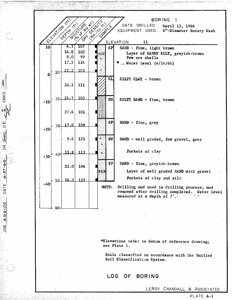
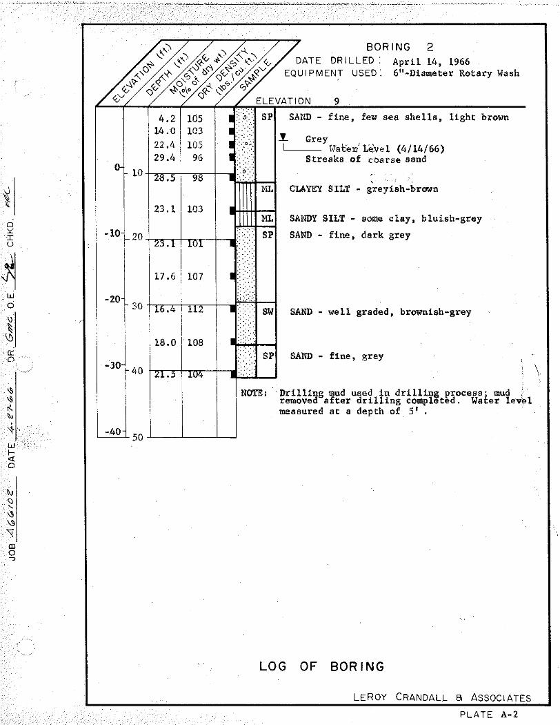
obtained for laboratory inspection and testing. The logs of the current borings are presented on
Figures A-1.1 through A-1.2; the logs from our prior borings are presented in our previous report in
Appendix D. The depths at which the undisturbed samples were obtained are indicated to the left of
the boring logs. The number of blows required to drive the Crandall sampler 12 inches using a
300 pound hammer falling 18 inches is indicated on the logs. The soils are classified in accordance
with the Unified Soil Classification System described on Figure A-2.
LABORATORY TESTS Laboratory tests were performed on selected samples obtained from the borings to aid in the
classification of the soils and to determine their engineering properties.
The field moisture content and dry density of the soils encountered were determined by performing
tests on the undisturbed samples. The results of the tests are shown to the left on the boring logs.
Direct shear tests were performed on selected undisturbed samples to determine the strength of the
soils. The tests were performed after soaking to near-saturated moisture content and at various
surcharge pressures. The yield-point values determined from the direct shear tests are presented on
Figure A-3, Direct Shear Test Data.
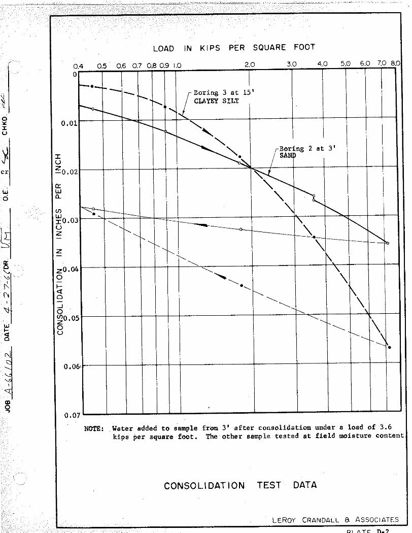
Confined consolidation tests were performed on one undisturbed sample to determine the
compressibility of the soils. Water was added to the sample during the tests to illustrate the effect

Proposed Belmont Plaza Olympic Pool Revitalization Project April 15, 2009 MACTEC Engineering and Consulting, Inc., Project 4953-09-0301
A-2
of moisture on the compressibility. The results of the tests are presented on Figure A-4,
Consolidation Test Data.
To determine the particle size distribution of the soils and to aid in classifying the soils, mechanical
analyses were performed on seven samples. The results of the mechanical analyses are presented
on Figures A-5.1 through A-5.4, Particle Size Distribution.
Soil corrosivity studies were performed on samples of the on-site soils. The results of the study and
recommendations for mitigating procedures are presented on Appendix D.

Proposed Belmont Plaza Olympic Pool Revitalization Project April 15, 2009 MACTEC Engineering and Consulting, Inc., Project 4953-09-0301
APPENDIX B
CONE PENETRATION TEST DATA

Proposed Belmont Plaza Olympic Pool Revitalization Project April 15, 2009 MACTEC Engineering and Consulting, Inc., Project 4953-09-0301
APPENDIX C
CORROSION STUDY

Proposed Belmont Plaza Olympic Pool Revitalization Project April 15, 2009 MACTEC Engineering and Consulting, Inc., Project 4953-09-0301
APPENDIX D
PRIOR REPORT OF GEOTECHNICAL INVESTIGATION


Maximum depth: 60.33 (ft)
Page 1 of 2
Kehoe Testing & EngineeringOffice: (714) 901-7270Fax: (714) [email protected]@msn.com
CPT Data 30 ton rig Customer: MACTECJob Site: Belmont Plaza Pool
Date: 06/Mar/2009Test ID: CPT-1Project: LongBeach
Test ID: CPT-1
File: Z06M0904C.ECP
0 700
Tip Stress COR
(tsf) 0 8
Sleeve Stress
(tsf) -1 10
Pore Pressure
(tsf) 0 8
Ratio COR
(%) 2 12
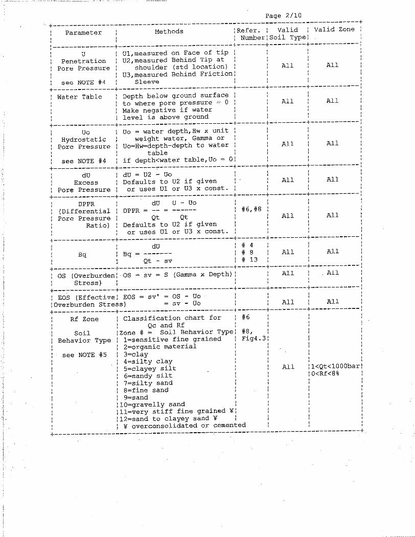
SBT FR
(Rob. 1986)
Silt Mix
Sand
Gr Sand
Sand
Sandy Silt
Silty Clay
Clay
Silt Mix
Sand Mix
Sand
Gr Sand
Sand
Gr Sand
Sand Mix
Gr Sand
Depth
(f
t)
0 0
10 10
20 20
30 30
40 40
50 50

Maximum depth: 60.33 (ft)
Page 2 of 2
Kehoe Testing & EngineeringOffice: (714) 901-7270Fax: (714) [email protected]@msn.com
CPT Data 30 ton rig Customer: MACTECJob Site: Belmont Plaza Pool
Date: 06/Mar/2009Test ID: CPT-1Project: LongBeach
Test ID: CPT-1
File: Z06M0904C.ECP
0 700
Tip Stress COR
(tsf) 0 8
Sleeve Stress
(tsf) -1 10
Pore Pressure
(tsf) 0 8
Ratio COR
(%) 2 12
SBT FR
(Rob. 1986)
Gr Sand
Sand
Gr Sand
Silty Sand
Depth
(f
t)
50 50
60 60
70 70
80 80
90 90
100 100

Maximum depth: 60.11 (ft)
Page 1 of 2
Kehoe Testing & EngineeringOffice: (714) 901-7270Fax: (714) [email protected]@msn.com
CPT Data 30 ton rig Customer: MACTECJob Site: Belmont Plaza Pool
Date: 06/Mar/2009Test ID: CPT-2Project: LongBeach
Test ID: CPT-2
File: Z06M0901C.ECP
0 700
Tip Stress COR
(tsf) 0 8
Sleeve Stress
(tsf) -1 10
Pore Pressure
(tsf) 0 8
Ratio COR
(%) 2 12
SBT FR
(Rob. 1986)
Sand Mix
Sandy Silt
Sand Mix
Sand
Gr Sand
Sand
Sandy Silt
Silt Mix
Sens. FR
Clay
Silt Mix
Sand
Gr Sand
Silt Mix
Gr Sand
Sand
Sandy Silt
Gr Sand
Sand Mix
Sand
Depth
(f
t)
0 0
10 10
20 20
30 30
40 40
50 50

Maximum depth: 60.11 (ft)
Page 2 of 2
Kehoe Testing & EngineeringOffice: (714) 901-7270Fax: (714) [email protected]@msn.com
CPT Data 30 ton rig Customer: MACTECJob Site: Belmont Plaza Pool
Date: 06/Mar/2009Test ID: CPT-2Project: LongBeach
Test ID: CPT-2
File: Z06M0901C.ECP
0 700
Tip Stress COR
(tsf) 0 8
Sleeve Stress
(tsf) -1 10
Pore Pressure
(tsf) 0 8
Ratio COR
(%) 2 12
SBT FR
(Rob. 1986)
Sand
Gr Sand
Sand Mix
Gr Sand
Depth
(f
t)
50 50
60 60
70 70
80 80
90 90
100 100

Maximum depth: 60.09 (ft)
Page 1 of 2
Kehoe Testing & EngineeringOffice: (714) 901-7270Fax: (714) [email protected]@msn.com
CPT Data 30 ton rig Customer: MACTECJob Site: Belmont Plaza Pool
Date: 06/Mar/2009Test ID: CPT-3Project: LongBeach
Test ID: CPT-3
File: Z06M0907C.ECP
0 700
Tip Stress COR
(tsf) 0 8
Sleeve Stress
(tsf) -1 10
Pore Pressure
(tsf) 0 8
Ratio COR
(%) 2 12
SBT FR
(Rob. 1986)
Silty Sand
Sand
Silty Clay
Clay
Silt Mix
Silty Clay
Sand Mix
Silt Mix
Silty Sand
Sand
Gr Sand
Sand
Sandy Silt
Silt Mix
Sand
Gr Sand
Sand
Depth
(f
t)
0 0
10 10
20 20
30 30
40 40
50 50

Maximum depth: 60.09 (ft)
Page 2 of 2
Kehoe Testing & EngineeringOffice: (714) 901-7270Fax: (714) [email protected]@msn.com
CPT Data 30 ton rig Customer: MACTECJob Site: Belmont Plaza Pool
Date: 06/Mar/2009Test ID: CPT-3Project: LongBeach
Test ID: CPT-3
File: Z06M0907C.ECP
0 700
Tip Stress COR
(tsf) 0 8
Sleeve Stress
(tsf) -1 10
Pore Pressure
(tsf) 0 8
Ratio COR
(%) 2 12
SBT FR
(Rob. 1986)
Sand
Silty Sand
Gr Sand
Sand
Depth
(f
t)
50 50
60 60
70 70
80 80
90 90
100 100
Maximum depth: 60.15 (ft)
Page 1 of 2
Kehoe Testing & EngineeringOffice: (714) 901-7270Fax: (714) [email protected]@msn.com
CPT Data 30 ton rig Customer: MACTECJob Site: Belmont Plaza Pool
Date: 06/Mar/2009Test ID: CPT-4Project: LongBeach
Test ID: CPT-4
File: Z06M0903C.ECP
0 700
Tip Stress COR
(tsf) 0 8
Sleeve Stress
(tsf) -1 10
Pore Pressure
(tsf) 0 8
Ratio COR
(%) 2 12
SBT FR
(Rob. 1986)
Sandy Silt
Silt Mix
Sand Mix
Sand
Silty Sand
Sand Mix
Silty Sand
Sand Mix
Silt Mix
Clay
Sand
Gr Sand
Silty Sand
Sand
Silty Sand
Sand
Gr Sand
Sand
Gr Sand
Depth
(f
t)
0 0
10 10
20 20
30 30
40 40
50 50

Maximum depth: 60.15 (ft)
Page 2 of 2
Kehoe Testing & EngineeringOffice: (714) 901-7270Fax: (714) [email protected]@msn.com
CPT Data 30 ton rig Customer: MACTECJob Site: Belmont Plaza Pool
Date: 06/Mar/2009Test ID: CPT-4Project: LongBeach
Test ID: CPT-4
File: Z06M0903C.ECP
0 700
Tip Stress COR
(tsf) 0 8
Sleeve Stress
(tsf) -1 10
Pore Pressure
(tsf) 0 8
Ratio COR
(%) 2 12
SBT FR
(Rob. 1986)
Gr Sand
Sand
Gr Sand
Sand
Sand
Interbedded
Depth
(f
t)
50 50
60 60
70 70
80 80
90 90
100 100
Maximum depth: 60.13 (ft)
Page 1 of 2
Kehoe Testing & EngineeringOffice: (714) 901-7270Fax: (714) [email protected]@msn.com
CPT Data 30 ton rig Customer: MACTECJob Site: Belmont Plaza Pool
Date: 06/Mar/2009Test ID: CPT-5Project: LongBeach
Test ID: CPT-5
File: Z06M0908C.ECP
0 700
Tip Stress COR
(tsf) 0 8
Sleeve Stress
(tsf) -1 10
Pore Pressure
(tsf) 0 8
Ratio COR
(%) 2 12
SBT FR
(Rob. 1986)
Sand
Sandy Silt
Sand
Silty Sand
Sand
Silty Sand
Sand
Silty Sand
Sand
Silty Clay
Silty Sand
Sand
Silty Sand
Sand
Gr Sand
Sand Mix
Sandy Silt
Gr Sand
Depth
(f
t)
0 0
10 10
20 20
30 30
40 40
50 50
Maximum depth: 60.13 (ft)
Page 2 of 2
Kehoe Testing & EngineeringOffice: (714) 901-7270Fax: (714) [email protected]@msn.com
CPT Data 30 ton rig Customer: MACTECJob Site: Belmont Plaza Pool
Date: 06/Mar/2009Test ID: CPT-5Project: LongBeach
Test ID: CPT-5
File: Z06M0908C.ECP
0 700
Tip Stress COR
(tsf) 0 8
Sleeve Stress
(tsf) -1 10
Pore Pressure
(tsf) 0 8
Ratio COR
(%) 2 12
SBT FR
(Rob. 1986)
Gr Sand
Sand
Gr Sand
Interbedded
Depth
(f
t)
50 50
60 60
70 70
80 80
90 90
100 100


GEOTECHNICAL INVESTIGATION FOR THE TEMPORARY MYRTHA POOL AND ASSOCIATED IMPROVEMENTS

INTRODUCTION
PURPOSE
This report presents the results of our geotechnical investigation for the temporary Myrtha Pool and associated improvements proposed in the existing public parking lot located to the east of the Belmont Plaza Olympic Pool Complex at 4000 Olympic Plaza within the City of Long Beach, California (see Plate 1 - Location Map). The purpose of this report is to provide a summary of our geotechnical investigation, data, and conclusions, and then provide geotechnical recommendations pertaining to site remedial grading and for the design and construction of the proposed temporary pool and associated site improvements.
SCOPE
1. Reviewed background information pertaining to the site, including published regional geologic maps and literature and a previous geotechnical report by Mactec for the adjacent Belmont Plaza Olympic Pool Complex.
2. Performed an initial site reconnaissance to assess current surface conditions and mark the site for Underground Service Alert.
3. Conducted a subsurface exploration program that consisted of the advancement of four CPT soundings each to a depth of 50 feet and the drilling of one hand-angered boring to a depth of 5 feet in order to physically observe the subsurface soils and to obtain samples for laboratory testing. The boring was logged by our senior engineer and samples were collected for laboratory testing.
4. Performed laboratory testing on a bulk sample that was collected during our subsurface exploration.
5. Interpreted and evaluated field conditions and laboratory data.
6. Perfo1med geotechnical engineering analyses using the field and laboratory data in conjunction with the conceptual site plan. The analysis addressed site seismicity, anticipated settlement, groundwater, liquefaction, and concrete flatwork and pool design.
7. Prepared this report which summarizes the results of our research, subsurface exploration, laboratory and field testing, analyses, conclusions, and recommendations relative to the proposed improvements at the subject site.

Ms. Pamela T. Burton, RJM DESIGN GROUP Proposed Temporary Myrtlm Pool, Belmont Plaza Revitalization, 4000 Olympic Plaza, Long Beacfl
SITE LOCATION AND DESCRIPTION
The temporary pool and associated improvements are proposed within a public parking lot located to the east of the Belmont Plaza Olympic Pool Complex which is located at 4000 Olympic Plaza within the City of Long Beach, California. This public parking lot is bordered on the west by Bennett A venue, on the north by a landscaped easement and then East Ocean Boulevard, and on the south by the beach (Pacific Ocean). The parking lot is also bordered on the south by an existing pool and by a City of Long Beach maintenance building and yard that have been constructed on the beach. To the west, the parking lot continues beyond the limits of planned improvements. The general location of the site with respect to nearby roadways is shown on Plate 1.
The existing parking lot is paved with asphalt, has light bollards and parking meters between the rows of parking stalls, and is surrounded by concrete curbs and gutters. At the end of the parking stalls are planters with groundcover and palm trees.
The parking lot appears to drain by sheet flow towards the north to northwest towards the intersection of East Ocean Boulevard and Bennett A venue. The pavement exhibits various levels of distress ranging from occasional cracks to extensive alligator cracking with local depressions. The distress is more extensive along the north side of the parking lot.
SITE RESEARCH AND PREVIOUS GEOTECHNICAL REPORTS
Reviewed materials for the site included geology maps and previously published geologic reports in order to identify site history and geologic conditions. These included:
• State of California Seismic Hazard Zones Map; Long Beach Quadrangle, base map prepared by U.S. Geologic Survey and dated 1964 (Photo revised 1981), Official Map Released March 3, 1999, Scale: 1inch=2000 feet
• Seismic Hazard Zone Report for the Long Beach 7.5-Minute Quadrangle, Los Angeles County, California, Seismic Hazard Zone Report 028 (California Division of Mines and Geology, 1998).
MACTEC previously performed a subsurface investigation for the adjacent Belmont Plaza Pool Complex (reference (I)). This investigation included the drilling of two exploratory borings each to a depth of76.5 feet using a hollow-stem auger drill rig and the advancement of five Cone Penetration Test (CPT) soundings each to a depth of 50 feet. Samples of the onsite soils were obtained by MACTEC for laboratory testing. Laboratory testing associated with this
April 3, 2013 2 GMU Project 12-137-00

Ms. Pamela T. Burton, RJM DESIGN GROUP Proposed Temporary Myrtha Pool, Belmont Plaza Revitalization, 4000 Olympic Plaza, Long Beach
previous investigation included in-place moisture content/dry density, particle size analysis, Atterberg limits, consolidation and shear strength characteristics, and soil cmrnsivity.
This report recommended that the complex building either be underpinned with new pile foundations and the exterior improvements be protected from lateral spreading by ground improvement, or that the entire structure be demolished, the entire building site improved by ground improvement, and then a new building constructed.
PLANNED IMPROVEMENTS
Based on our conversations with representatives ofRJM Design Group, it is our understanding that a portion of the existing parking lot to the east of the Belmont Plaza Olympic Pool Plaza will be removed and replaced with a large concrete slab that will support a temporary above-ground Myrtha pool. Two-thirds of the pool will be constructed on-grade and will be supported on a 12-inch-thick concrete slab. The remaining one-third of the pool will be constructed on 3 feet of new fill and the 12-inch-thick concrete slab. The pool walls will be constructed as braced stainless steel walls. The concrete slab will also support the braced walls while isolated concrete footings will support the raised decking and bleachers that will surround the pool.
Other improvements include temporary restroom/shower and office trailers, temporary asphalt walkways and curbs, planter areas, fencing, and 70- to 80-foot-high light poles. Some of the existing asphalt paving will also be covered with slurry and restriped.
Based on the current plans, the majority of the site will remain at existing grades; therefore, only minor cuts and fills will be required within most areas. However, the deep portion of the temporary pool will require cuts of up to 12 inches while the shallow portion of the pool will require fills of up to 3 feet to reach proposed bottom of slab grades.
SUBSURFACE EXPLORATION
Our subsurface investigation consisted of the advancement of four CPT soundings (CPT-1 through CPT-4) each to a depth of 50 feet to obtain continuous geotechnical information of the subsurface soils. In addition, a single hand-augered drill hole was advanced within a planter area to a depth of 5.5 feet to physically observe the subsurface soils and to obtain a bulk sample for geotechnical testing. The drill hole was logged by our senior engineer. The locations of the CPT soundings and drill hole are shown on Plate 2-Geotechnical Map, and the log of the drill hole and the results of the CPT soundings are included in Appendix A.
April 3, 2013 3 GMU Project 12-137-00

Ms. Pamela T. Burton, RJM DESIGN GROUP Proposed Temporary Myr/ha Pool, Belmont Plaza Revitalization, 4000 Olympic Plaza, Long Beach
MONITORING WELLS
In order to determine depths to groundwater, two monitoring wells were installed within the site. These monitoring wells were both 20 feet deep and were comprised of2-inch diameter slotted pipes installed within 8-inch diameter drilled holes. The space around the slotted pipes was backfilled with clean sand to within 3 feet of existing grade and then capped with 2 feet ofbentonite to seal the wells from surface water.
LABORATORY TESTING
Laboratory testing for the subject investigation was performed to dete1mine the expansion potential and corrosion characteristics of the onsite soils. Corrosion testing included the determination of soluble sulfate and chloride concentrations, and soil pH and electrical resistivity. Laboratory procedures and test results are presented in Appendix B- Geotechnical Laboratory Procedures and Test Results. Pertinent laboratory test data is also shown on our recent drill hole log.
Laboratory test results on samples collected at the site indicate that onsite soils are:
• Non-expansive • Moderately corrosive to concrete • Corrosive to ferrous metals
GEOLOGIC FINDINGS
LOCAL GEOLOGY AND SUBSURFACE SOIL CONDITIONS
The site is located within an area that has been significantly altered by the construction of marunade islands and landforms and is underlain by undifferentiated older and younger artificial fill that has been placed over native young alluvium and estuarine deposits. Within our CPT soundings, it was not possible to differentiate between the fill and the native soils.
Our recent drill hole and CPT soundings indicate that the site is underlain by approximately 8 to 13 feet of poorly graded sand and silty sand, a 4- to 15-foot-thick layer of intermixed clay and silty clay, and then poorly graded sand and silty sand to the maximum depth explored (50 feet). Within the southern portion of the site, the clay layer is located approximately 13 feet below the ground surface and is 4 to 6.5 feet thick, while in the northern portion of the site, the clay layer is
April 3, 2013 4 GMU Project 12-137-00
Ms. Pamela T. Burton, RJM DESIGN GROUP Proposed Temporary Myrl/ia Pool, Be/mo11t PlllZll RevilllfiZllti011, 4000 Olympic PlllZll, Long Bellclr
located approximately 8 to 9 feet below the ground surface and is approximately 9 to 15 feet thick. The poorly graded sands and silty sands are loose to medium dense with rootlets in the upper 12 to 18 inches, becoming medium dense to dense below while the underlying clays and silty clays are firm.
At the locations of the CPT soundings, the existing asphalt was observed to range from approximately 2.5 to 3 inches thick. The underlying base is intermixed with varying amounts of sand and ranges from approximately 6 to 7 inches thick.
GROUNDWATER
Groundwater was originally measured within our drill hole and CPT soundings at the time of our subsurface exploration. Groundwater was measured three more times within our monitoring wells. The groundwater depths ranged from 6 to 6.8 feet below existing grades. These depths to groundwater are in general agreement with the depths of historically high groundwater provided in the reference (2) Seismic Hazard Zone Map for the Long Beach Quadrangle. Since the project does not include any subsurface structures, groundwater is not expected to adversely impact the proposed grading or construction.
FAULTING AND SEISMICITY
The site is not located within an Official Alquist-Priolo Earthquake Fault Zone and no known active faults are shown on current geologic maps for the site. The nearest known active fault is the Newport-Inglewood Fault, which is located approximately 2.3 kilometers from the site and is capable of generating a maximum earthquake magnitude (Mw) of 7 .1. The site is also located within 1 0. 1 kilometers of the Palos Verdes fault, which is capable of generating a maximum earthquake magnitude (Mw) of7.3. Given the proximity of the site to these and numerous other active and potentially active faults, the site will likely be subject to earthquake ground motions in the future.
In order to evaluate the likelihood of future earthquake ground motions occurring at the site, a probabilistic seismic hazard analysis (PSHA) of horizontal ground shaking was perfotmed using the commercial computer program EZ-FRISK ver. 7.43. The PSHA utilized seismic sources and attenuation equations consistent with the 2008 USGS National Seismic Hazard Mapping Project. Assuming a conservative risk level of 10 percent probability of exceedance in 50 years (i.e., -475 year ARP), the PHGA is 0.38g.
It should be noted that this peak ground acceleration has a 10 percent probability of being exceeded in 50 years (which is roughly equivalent to the design life of an average long-term development).
April 3, 2013 5 GMUProject 12-137-00

Ms. Pamela T. Burton, RJM DESIGN GROUP Proposed Temporary Myrtlia Pool, Belmo11/ Plaza Revitalizatio11, 4000 Olympic Plaza, Long Beach
For the subject project, the temporary Myrtha pool will only be used for approximately 2 years or less and the probability of a significant earthquake occurring during this time span is so low that the corresponding PGA would be essentially zero. Therefore, the PGA we used can be considered to be very conservative for this temporary structure.
SEISMIC HAZARD ZONES
The subject property is not located within an area mapped as having the potential for seismicinduced landsliding; however, it is located within an area mapped as having the potential for seismicinduced liquefaction as shown on the reference (2) Seismic Hazard Zone Map for the Long Beach Quadrangle.
GEOTECHNICAL ENGINEERING FINDINGS
LIQUEFACTION, SEISMIC SETTLEMENT, AND LATERAL SPREADING
Liquefaction Investigation
Since the site is located within a zone mapped as having the potential for earthquake induced liquefaction, liquefaction and related hazards were quantitatively evaluated utilizing 1he CPT soundings to a maximum depth of 50 feet.
Design Earthquake and Mode Magnitude
Based on our site specific PSHA with deaggregation, a very conservative PGA of 0.38g, Modal Magnitude 7.2, and modal distance of 11.2 km were calculated for this study.
Design Groundwater Level
Actual groundwater levels encountered during our recent exploration indicate a groundwater level of approximately 6 to 6.5 feet below existing site grades, which are in agreement with the depths of historically high groundwater provided in the reference (2) Seismic Hazard Zone Map for the Long Beach Quadrangle. Therefore our analysis was performed using the worst case condition (5 feet b.g.s.).
April 3, 2013 6 GMU Project 12-137-00

Ms. Pamela T. Burton, RJM DESIGN GROUP Proposed Temporary Myrilla Pool, Belmo11t Plaza Revitalizatio11, 4000 Olympic Plaza, Lo11g Beaclt
Liquefaction Analyses
GMU utilized CLiq to evaluate CPT data for liquefaction. CLiq is a commercial computer software program that applies the latest NCEERmethods for liquefaction analysis including post-earthquake settlement and lateral displacement.
Liquefaction, Seismic Settlement, and Lateral Spreading Potential
Our analysis indicates that discrete zones within the underlying soils below the groundwater level may be subject to liquefaction during a design seismic event. Based on our analysis, the site has a slight to moderate potential for any adverse effects of liquefaction due to the depth and discrete nature of the liquefiable zones. Liquefaction seismic settlement calculations indicate approximately 0.3 to 1. 75 inches of settlement could occur during a design earthquake. The results of our analyses are presented in Appendix C.
The site also has a moderate potential for adverse effects due to seismic-induced lateral spreading. Our calculations indicate that lateral displacements at the points of exploration could range from approximately 9 to 80 inches. The results of our analyses are presented in Appendix C.
Based on the thickness and depth ofliquefiable layers shown in our liquefaction analysis (Appendix C), the guidelines provided by Southern California Earthquake Center (1999), and the design curves proposed by Ishihara (1985) which provide criteria for identifying conditions causing or not causing damage to foundations, the site is not anticipated to be subject to liquefaction-induced foundation bearing failure.
Although there is the potential for liquefaction-induced settlement and lateral spreading using the very conservative design PGA, the actual probability of a seismic event actually occurring during the short time of service for the proposed temporary pool is essentially zero. However, due to this very small potential, it is recommended that the pool be underlain by a reinforced concrete slab described in a subsequent section of this report. This slab will help mitigate the potential for liquefaction to adversely affect the proposed temporary pool.
STATIC SETTLEMENT/COMPRESSIBILITY
The on-site granular soils were found to be medium dense to dense while the fine-grained soils were found to be firm and are not susceptible to significant consolidation. Total static settlements can be expected to range from approximately Y, to %-inch with a differential settlement of Yi-inch over a span of 40 feet.
April 3, 2013 7 GMUProject 12-137-00

Ms. Pamela T. Burton, RJM DESIGN GROUP Proposed Temporary Myrtlia Pool, Belmo11t Plaza Revitalizatio11, 4000 Olympic Plaza, Lo11g Beac/1
SOIL EXPANSION
The on-site granular soils to depths of at least 8 feet are non-expansive while the underlying clay can be classified as having a moderate expansion potential based on our assessment of the soil classifications provided in the CPT logs in Appendix A and the results of expansion index testing contained in Appendix B. A non-expansive potential should therefore be assumed for planning purposes of the structures proposed on-grade.
SOIL CORROSION
To evaluate the corrosion potential of the on-site soils to both ferrous metals and concrete, representative samples were tested for pH, minimum resistivity, soluble chlorides, and soluble sulfates. The results of chemical testing contained in Appendix B indicate that the soil sample tested contains a negligible concentration of sulfates and severe concentrations of chlorides. In addition, due to the proximity of the site to the nearby ocean, there is a high potential for onsite structures to come in contact with seawater. Thus, the onsite soils should be considered moderately corrosive to concrete and severely corrosive to ferrous metals.
EXCAVATION CHARACTERISTICS
Ripp ability
The soil materials underlying the site can be easily excavated with conventional grading equipment such as loaders, excavators, and backhoes.
Trenching
We expect that excavation of new utility trenches can be accomplished utilizing conventional trenching machines and backhoes. Trench support requirements will be limited to those required by safety laws or other locations where trench slopes will need to be flattened or supported by shoring designed to suit the specific conditions exposed.
Volume Change
For the rough determination of earthwork quantities, we estimate that the change in volume of on-site disturbed surficial fills that are excavated and placed as new compacted fill at an average relative compaction of92% will result inan average of about 5% loss in volume. It should be noted thatthe aforementioned value is approximate and is for rough planning purposes only.
April 3, 2013 8 GMU Project 12-137-00

Ms. Pamela T. Burton, RJM DESIGN GROUP Proposed Temporary Myrl/ta Pool, Belmont Plaza Revitalization, 4000 Olympic Plaza, Long Beacll
CONCLUSIONS AND RECOMMENDATIONS
DEVELOPMENT FEASIBILITY
Based on the geologic and geotechnical findings, it is our opinion that proposed grading and construction is feasible and practical from a geotechnical standpoint if accomplished in accordance with the City of Long Beach grading and building requirements and the recommendations presented herein. It is also the opinion of GMU Geotechnical that proposed grading and construction will not adversely affect the geologic stability of adjoining properties provided grading and construction are performed in accordance with the recommendations provided in this report.
A summary of conclusions is as follows:
1. The site should be considered developable and not expected to adversely impact adjacent properties from a geotechnical perspective utilizing standard grading techniques.
2. Site soils are artificial fill materials overlying native alluvial and estuarine deposits. The upper 12 to 18 inches of the fill materials are medium dense and will require re-processing.
3. Groundwater was measured at 6 to 6.8 feet below existing grade, which agrees with the historic high groundwater level.
4. There are no known active faults within the subject site. The site seismicity is typical for the Long Beach area. Structure design should be in accordance with the current CBC.
5. Based on visual observations and laboratory testing of the on-site materials, corrective grading at the site will be limited to the overexcavation and recompaction of the surficial engineer fill materials that are expected to be disturbed during demolition operations within the site. Additional removals may be necessary depending on the materials encountered during grading.
6. Some of the existing asphalt pavement sections will need to be demolished. Due to the limited amount of grading and fill placement that will occur, the old asphalt and base materials generated from the removal of the existing pavement sections should be collected and hauled off-site.
7. Existing subsurface utility lines, depending on their depths and locations in relation to the proposed development, may need to be excavated and removed, or abandoned in-place.
8. The potential for liquefaction and lateral spreading is conservatively estimated to be low to
April 3, 2013 9 GMU Project 12-137-00

Ms. Pamela T. Burton, RJM DESIGN GROUP Proposed Temporary Myrtha Pool, Belmo11f Plaza Revitalizatio11, 4000 Olympic Plaza, Long Beach
moderate. Due to the short service life of the temporary pool, the probability is essentially zero. Estimated vertical seismic settlements range from 0.3 to 1.75 inches with a differential seismic settlement of less than Yi-inch over a span of 40 feet. Lateral displacements at the points of exploration could range from approximately 9 to 80 inches. Due to the very remote possibility of seismic-induced settlement and lateral spreading as a result of liquefaction, the temporary pool should be constructed on a reinforced concrete slab.
9. Site soils to a depth of at least 8 feet are non-expansive. Future site improvements will not require any special design for expansive soil conditions.
10. C01Tosion testing indicates that the on-site soils are severely corrosive to ferrous metals. Consequently, any metal exposed to the soil will need protection and all reinforcing steel will need to be properly covered by concrete.
11. The on-site testing indicates negligible amounts of sulfate. However, due to the proximity of the site to the nearby ocean, there is a high potential for onsite structures to come in contact with seawater. Therefore, it is recommended that a moderate level of sulfate exposure (i.e., Type II/V cement with a water/cement ratio of 0.50) be assumed for proposed concrete slabs.
SITE PREPARATION AND GRADING
General
The subject site should be precise graded in accordance with the City of Long Beach grading code requirements (and all other applicable codes and ordinances) and the recommendations as outlined in the following sections of this report. The geotechnical aspects of future grading plans and improvement plans should be reviewed by GMU Geotechnical prior to grading and construction. Particular care should be taken to confirm that all project plans conform to the recommendations provided in this report. All plarmed and corrective grading should also be monitored by GMU Geotechnical to verify general compliance with the recommendations outlined in this report.
Demolition and Clearing
Prior to the start of the plarmed improvements, some of the existing asphalt pavement will need to be demolished. The old asphalt and base materials generated from the removal of the existing pavement sections may be collected and used as compacted fill provided that it is thoroughly crushed and broken down with no fragments greater than 3 inches in maximum diameter.
The on-site soils are suitable for use as compacted fill from a geotechnical perspective if care is taken to remove all significant organic and other decomposable debris.
April 3, 2013 10 GMU Project 12-137-00

Ms. Pamela T. Burton, RJM DESIGN GROUP Proposed Temporary Myrtha Pool, Belmolll Plaza Revitalizatio11, 4000 Olympic Plaza, Lo11g Beach
Cavities and excavations created upon removal of subsurface obstructions, such as existing buried utilities, should be cleared of loose soil, shaped to provide access for backfilling and compaction equipment, and then backfilled with properly compacted fill.
The project geotechnical consultant should provide periodic observation and testing services during demolition operations to document compliance with the above recommendations. In addition, should unusual or adverse soil conditions or buried structures be encountered during grading that are not described herein, these conditions should be brought to the immediate attention of the project geotechnical consultant for corrective recommendations.
Corrective Grading- Existing Grades
Existing soils that comprise the upper 12 to 18 inches feet of the site are damp to moist and medium dense. In addition, it is expected that the surficial soils will be disturbed during the demolition of the existing asphalt pavement sections. Therefore, to provide adequate support of proposed improvements, the subgrade soils exposed after demolition should be overexcavated to a depth of at least 18 inches, moisture conditioned (as necessary) to at least 2% above the optimum moisture content, and then replaced as properly compacted fill at a minimum relative compaction of90%.
FILL MATERIAL AND PLACEMENT
Suitability
All on-site soils are considered suitable for use as compacted fill from a geotechnical perspective if care is taken to remove all significant organic and other decomposable debris, and separate and stockpile rock materials larger than 6 inches in maximum diameter.
Compaction Standard and Methodology
All soil material used as compacted fill, or material processed in-place or used to backfill trenches, should be moistened, dried, or blended as necessary and densified to at least 90% relative compaction as determined by ASTM Test Method D 1557. It is recommended that fills be placed a minimum of 2% above optimum moisture content.
Material Blending
The existing surficial engineered fill materials are expected to be generally slightly below optimum moisture content but may have variable moisture content depending on the season in which work is performed. The majority of the materials to be handled during grading will require some blending
April 3, 2013 II GMU Project 12-137-00

Ms. Pamela T. Burton, RJM DESIGN GROUP Proposed Temporary Myrtlra Pool, Bel111011/ Plaza Revilalizatio11, 4000 Olympic Plaza, Lo11g Beacfl
and addition of water to meet acceptable moisture ranges for sufficient compaction (i.e., minimum 2% above optimum moisture content).
Use of Rock or Broken Asphalt
As described previously, the existing asphalt and base materials may be used as new fill provided that it is thoroughly crushed and broken down with no fragments greater than 3 inches in maximum diameter. In addition, these materials should also be blended with the onsite soils prior to being placed as compacted fill.
TEMPORARY EXCAVATION STABILITY
Trench excavations will also be required for new utility lines, if any. The sidewalls of these temporaty excavations are expected to expose non-cohesive granular silty sands and sands.
Based on the anticipated engineering characteristics of these materials, tempora1y excavations for any new utility trench walls to a depth of 3 feet may be made vertically without shoring subject to verification of safety by the contractor. Deeper excavations should be braced, shored, or sloped back no steeper than I: 1 (horizontal to ve1iical). In addition, no surcharge loads should be allowed within 5 feet of the trench walls.
We anticipate the trench walls to be temporarily stable to a height of 3 feet provided the above recommendations are followed. However, deeper excavations will encounter saturated conditions or groundwater which will adversely affect the stability of the trench bottoms and sidewalls. Modifications to our recommendations may be required based on our observations of the actual conditions exposed in the field.
Our temporary excavation recommendations are provided only as general guidelines and all work associated with temporary excavations should meet the minimal requirements as set forth by CAL-OSHA. Temporary slope and trench excavation construction, maintenance, and safety are the responsibility of the contractor.
POST-GRADING CONSIDERATIONS
Utility Trench Backfill Considerations
Backfill compaction of utility trenches should be such that no significant settlement will occur. Backfill for all of these trenches should be compacted to at least 90% relative compaction subject to sufficient observation and testing. In the event that granular material having a sand equivalent of30
April 3, 2013 12 GMU Project 12-137-00

Ms. Pamela T. Burton, RJM DESIGN GROUP Proposed Temporary Myrtha Pool, Belmo11I Plaza Revitalizatio11, 4000 Olympic Plaza, Lo11g Beach
or greater is used for backfill and this material is thoroughly flooded into place, extensive testing is not required. If native material with a sand equivalent less than 30 is used for backfill, it should be placed at near-optimum moisture content and mechanically compacted.
Jetting or flooding will not densify native soil materials with a sand equivalent less than 30 due to its silty to clayey nature. Also, jetting or flooding of granular material should not be used to consolidate backfill in trenches adjacent to any foundation elements.
Where trenches closely parallel a footing (i.e., for retaining walls) and the trench bottom is located within a 1 horizontal to 1 vertical plane projected downward and outward from any structure footing, concrete slurry backfill should be utilized to backfill the portion of the trench below this plane. The use of concrete slurry is not required for backfill where a narrow trench crosses a footing at about right angles.
· We suggest that these recommendations be included as a specification in all subcontracts for underground improvements. In addition, the design of all underground conduits, pipelines, or utilities should also consider the potentially corrosive nature of the on-site soils to metals, as previously described in this report.
Surface Drainage
Surface drainage should be carefully controlled to prevent runoff over graded slope surfaces and ponding of water on flat pad areas. Positive drainage away from graded slopes is essential to reduce the potential for erosion or saturation of slope surfaces. All drainage at the site should be in minimum conformance with the applicable City of Long Beach codes and standards.
PRELIMINARY FOUNDATION DESIGN RECOMMENDATIONS
Structure Seismic Design
No active or potentially active faults are known to cross the site, therefore, the potential for primary ground rupture due to faulting on-site is very low to negligible. However, the site will likely be subject to seismic shaking at some time in the future. For design of future buildings, retaining walls, or other structural improvements, site-specific seismic design parameters were determined using the USGS computer program titled "Seismic Hazard Curves and Uniform Hazard Response Spectra, Version 5.0.8." The site coordinates used in the analysis were 33.7579° North Latitude and 118.1441 ° West Longitude and the site class designation "D" was determined by the shear wave testing performed within the CPT-1 sounding. On-site structures should be designed in accordance with the following 2010 CBC criteria:
April 3, 2013 13 GMU Project 12-137-00

Ms. Pamela T. Burton, RJM DESIGN GROUP Proposed Temporary Myrtlw Pool, Belmo11t Plaw Revitalizatio11, 4000 Olympic Plaza, Lo11g Beach
Parameter Factor Value 0.2s Period Spectral Response S, l.742g I.Os Period Spectral Response s, 0.665g
Soil Profile Type Site Class D Site Coefficient Fa 1.0 Site Coefficient Fv 1.5
Adjusted Spectral Response SM, l.742g SM1 0.998g
Adjusted Spectral Response SD, l.161g SD1 0.665g
It should be recognized that much of southern California is subject to some level of damaging ground shaking as a result of movement along the major active (and potentially active) fault zones that characterize this region. Design utilizing the 2010 CBC is not meant to completely protect against damage or loss of function. Therefore, the preceding parameters should be considered as minimum design criteria.
CONCRETE SLAB DESIGN
Modulus of Subgrade Reaction
For the design of the concrete slab to support the temporary pool, a modulus of subgrade reaction of 150 pci may be used.
Thickness and Reinforcement
The temporary pool and suTI"ounding pool decking and bleachers will be supported on a new concrete slab. Since this new slab may be exposed to future movements (including liquefaction-induced settlement and lateral spreading), it should have a minimum thickness of 12 inches and be minimally reinforced with No. 4 bars at 18 inches on center.
Final determination of slab thickness and reinforcement should be determined by the structural engineer based on actual loading conditions.
Subgrade Soil Moisture Content
The foundation subgrade should be moisture conditioned/pre-saturated as necessary to at least 2% over the optimum moisture content to a minimum depth of 18 inches. The moisture content of the subgrade soils should be verified by GMU prior to initiating foundation construction.
April 3, 2013 14 GMU Project 12-137-00
Ms. Pamela T. Burton, RJM DESIGN GROUP Proposed Temporary Myrllw Pool, Belmolll Plaza Revita/izatio11, 4000 Olympic Plaza, Long Beacil
CONCRETE
It is anticipated that the onsite soils will have a moderate sulfate exposure per Section 1904.3 of the 2010 CBC. Therefore, Type 1lN cement along with a maximum water/cement ratio of 0. 50 should be used for all concrete in contact with the onsite soils. This recommendation will serve to minimize the potential of water and/or vapor transmission through the concrete and minimize the potential for physical attack to concrete from non-sulfate based salts. In addition, wet curing of the concrete as described in ACI Publication 308 should be considered.
The aforementioned recommendations in regards to concrete are made from a soils perspective only. Final concrete mix design as well as any concrete testing is outside our purview. All applicable codes, ordinances, regulations, and guidelines should be followed in regard to designing a durable concrete with respect to the potential for detrimental exposure from the on-site soils and/or changes in the environment.
CORROSION PROTECTION OF METAL STRUCTURES
The results of the laboratory chemical tests performed on soil samples collected within and adjacent to the subject area indicate that the on-site soils are severely corrosive to ferrous metals. Consequently, metal structures which will be in direct contact with the soil (i.e., underground metal conduits, pipelines, metal sign posts, metal door frames, etc.) and/or in close proximity to the soil (wrought iron fencing, etc.) may be subject to corrosion. The use of special coatings or cathodic protection around buried metal structures has been shown to be beneficial in reducing corrosion potential. The potential for corrosion of ferrous metal reinforcing elements embedded in structural concrete will be reduced by the use of the recommended maximum water/cement ratio for concrete.
The laboratory testing program performed for this project does not address the potential for corrosion to copper piping. In this regard, a corrosion engineer should be consulted to perform more detailed testing and develop appropriate mitigation measures (if necessary). Otherwise, the on-site soils should be considered corrosive to copper.
The above discussion is provided for general guidance in regards to the corrosiveness of the on-site soils to typical metal structures used for construction. Detailed corrosion testing and recommendations for protecting buried ferrous metal and/or copper elements is beyond our purview.
FOUNDATIONS FOR RAISED DECKS, BLEACHERS AND FENCING
The raised decks and bleachers and the fencing around the pool will be supported on individual footings. Recommendations for these footings are provided in the following section.
April 3, 2013 15 GMU Project 12-137-00

Ms. Pamela T. Burton, RJM DESIGN GROUP Proposed Temporary Myrtha Pool, Belmo11/ Plaza Revitalizalio11, 4000 Olympic Plaza, Long Beach
Foundation Design Parameters
• Minimum Foundation Width 18 inches
• Minimum Depth 18 inches below lowest outside adjacent grade
• Bearing Materials Engineered fill
• Minimum Footing Reinforcement Four #4 bars; two at top and two at bottom of footing
• Allowable Bearing Capacity 2,000 psf with minimum embedment of 18 inches (may be increased 20% for each additional foot of width or embedment to a maximum of 3,000 psf).
• Coefficient of Friction 0.35
• Unit Weight of Backfill 125 pcf
• Passive Earth Pressure 250 pcf on flat ground (disregard upper 6 inches and reduce passive by one-third when combining friction and passive pressure).
• Concrete
POLE FOUNDATIONS
0.50 w/c ratio; Type IIN cement (geotechnical perspective only).
Pole foundations will be required for new light bollards within the subject site. As a minimum, the pole foundations should be at least 18 inches in diameter and at least 3 feet deep; however, the actual dimensions should be determined by the project structural engineer based on anticipated lateral loads and on the following design parameters.
Bearing Materials. The pole foundations may bear into competent native soils approved by a representative from GMU.
Bearing Values. End-bearing capacity and skin friction may be combined to determine the allowable bearing capacities of the pole foundations. An allowable bearing pressure of 2000 pounds per square foot (psf) may be used for pole foundations at least 18 inches in diameter and embedded a minimum of 3 feet below the lowest adjacent grade. A value of
April 3, 2013 16 GMU Project 12-137-00

Ms. Pamela T. Burton, RJM DESIGN GROUP Proposed Temporary Myrt/w Pool, Be/mo11t Plaza Revita/izatio11, 4000 Olympic Plaza, Long Beacli
250 pounds per square foot may be used to determine the skin friction between the concrete and surrounding soil.
Lateral Load Design. Lateral loads may be resisted by friction at the base of the foundations and by passive resistance within the adjacent earth materials. A coefficient of friction of0.35 may be used between the foundations and the recommended bearing material. For passive resistance, an allowable passive earth pressure of 200 pounds per foot of pile diameter per foot of depth into competent bearing material may be used; however, passive resistance should be disregarded within the upper 2 feet due to possible disturbance during drilling. The passive resistance may be assumed to be acting over an area equivalent to two pile diameters.
Construction Considerations. It should be noted that the site is underlain by shallow groundwater. Groundwater can be expected to be encountered at a depth of approximately 6 feet below the existing ground surface. As a result of capillary action, the subsurface soils can be expected to be saturated at a depth of 5 feet below the existing ground surface. Based on these conditions, severe caving can be expected to occur within the pole foundation excavations below a depth of 5 feet. Therefore, temporary casing will be required to advance the pole foundation excavations to their required depths.
NEW ASPHALT PAVEMENT AND SLURRY
It is proposed to construct new asphalt walkways on top of the existing asphalt pavement to support pedestrian traffic. New asphalt will also be placed on top of the existing asphalt pavement to support the new restroom/shower trailers and office trailer.
It is recommended that this new asphalt be at least 3 inches thick and that the existing asphalt be cleaned and tack coated prior to the placement of the new asphalt.
It is also proposed to slurry a portion of the existing parking lot that will serve as the main access to the existing parking lot. Since this area of proposed slurry will serve as the main access, it is expected that it will experience a significant amount of traffic. In addition, during our site reconnaissance end subsurface exploration, it was noted that the existing asphalt is in very poor condition with extensive cracking, depressions, and areas where the asphalt has completely fragmented and broken apart. Therefore, in lieu of conventional slurry, it is recommended that the existing pavement be covered with a higher strength "chip" seal or "cape" seal. Specific recommendations for these products can be provided, if requested.
April 3, 2013 17 GMU Project 12-137-00

Ms. Pamela T. Burton, RJM DESIGN GROUP Proposetl Temporary Myrl/ta Pool, Belmo11/ Plaza Revilalizalio11, 4000 Olympic Plaza, Lo11g Benell
FUTURE PLAN REVIEW
GMU should review future project plans to check for conformance to the recommendations provided herein, and to provide additional recommendations as needed. Specifically, GMU should review the final grading plans and landscape plans.
GEOTECHNICAL OBSERVATION AND TESTING
It is recommended that geotechnical observation and testing be performed by this firm during the following stages of grading and construction:
• During site clearing and grubbing.
• During all phases of grading including corrective grading, scarification, ground preparation, moisture conditioning, and placement and compaction of all fill materials.
• During placement and compaction of aggregate base.
• During excavation of foundations for new walls and similar structures.
• When any unusual conditions are encountered.
LIMITATIONS
All parties reviewing or utilizing this report should recognize that the findings, conclusions, and recommendations presented represent the results of our professional geological and geotechnical engineering efforts and judgments. Due to the inexact nature of the state of the art of these professions and the possible occurrence of undetected variables in subsurface conditions, we cannot guarantee that the conditions actually encountered during grading and site construction will be identical to those observed, sampled, and interpreted during our study, or that there are no unknown subsurface conditions which could have an adverse effect on the use of the property.
We have exercised a degree of care comparable to the standard of practice presently maintained by other professionals in the fields of geotechnical engineering and engineering geology, and believe that our findings present a reasonably representative description of geotechnical conditions and their probable influence on the grading and use of the property.
April 3, 2013 18 GMU Project 12-137-00

Ms. Pamela T. Burton, RJM DESIGN GROUP Proposed Temporary Myrtlta Pool, Belmont Plaza Revitalization, 4000 Olympic Plaza, Long Beaclt
Because our conclusions and recommendations are based on a limited amount of current and previous geotechnical exploration and analysis, all parties should recognize the need for possible revisions to our conclusions and recommendations during grading of the project.
Additionally, our conclusions and recommendations are based on the assumption that our firm will act as the geotechnical engineer of record during construction and grading of the project to observe the actual conditions exposed, to verify our design concepts and the grading contractor's general compliance with the project geotechnical specifications, and to provide our revised conclusions and recommendations should subsurface conditions differ significantly from those used as the basis for our conclusions and recommendations presented in this report.
It should be further noted that the recommendations presented herein are intended solely to minimize the effects of post-construction soil movements. Consequently, minor cracking and/or distortion of all on-site improvements should be anticipated.
SUPPORTING DATA
The following Plates and Appendices which complete this report are listed in the Table of Contents.
dwh/12-137-00R (4-3-13)
April 3, 2013
Respectfully submitted,
GMU GEOTECHNICAL, INC.
David Hansen, M.Sc., RCE 56591 Senior Geotechnical Engineer
Gregory Silver, M.Sc., PE, GE 2336 Principal Geotechnical Engineer
19 GMU Project 12-137-00

Ms. Pamela T. Burton, RJM DESIGN GROUP Proposed Temporary Myrtha Pool, Belmo11t Plaza Revitalizatio11, 4000 Olympic Plaza, Lo11g Beac/1
REFERENCES
SITE-SPECIFIC REFERENCE
(1) "Report of Preliminary Geotechnical Investigation, Proposed Belmont Plaza Olympic Pool Revitalization Project, 4000 East Olympic Plaza, Long Beach, California," report by MACTEC, dated April 14, 2009.
TECHNICAL REFERENCES
Boore, D.M. and Atkinson, G.M., 2008, Ground-Motion Prediction Equations for the Average Horizontal Component of PGA, PGV, and 5%-Damped PSA at Spectral Periods between 0.01 sand 10 s: Earthquake Spectra, Vol. 24, No. 1, p. 99-138.
California Geologic Survey, 2008, Guidelines for Evaluating and Mitigating Seismic Hazards in California: CGS Special Publication 117 A.
Campbell, K.W., and Bozorgnia, Y., 2008, NGA Ground Motion Model for the Geometric Mean Horizontal Component of PGA, PGV, PGD, and 5% Damped Linear Elastic Response Spectra for Periods Ranging from 0.01 to !Os: Earthquake Spectra, Vol. 24, No. 1, p. 139-171.
Chiou, B.S., and Youngs, R.R., 2008, An NGA Model for the Average Horizontal Component of Peak Ground Motion and Response Spectra: Earthquake Spectra, Vol. 24, No. 1, p. 173-215.
"Seismic Hazard Zone Report for the Long Beach 7.5-Minute Quadrangle, Los Angeles County, California," prepared by the Department of Conservation, Division of Mines and Geology, Seismic Hazard Zone Report 028, dated 1998.
"State of California Seismic Hazard Zones Map; Long Beach Quadrangle," base map prepared by U.S. Geologic Survey and dated 1964 (Photo revised 1981), Official Map Released March 3, 1999, scale: 1 inch= 2000 feet.
April 3, 2013 20 GMU Project 12-137-00

PRELIMINARY GEOTECHNICAL REPORT