appendix d - king county, washington · 2005 surface water design manual – appendix d 1/24/2005...
TRANSCRIPT

APPENDIX D
EROSION AND SEDIMENT CONTROL (ESC) STANDARDS
KING COUNTY, WASHINGTON
SURFACE WATER DESIGN MANUAL
King County
Department of Natural Resources and Parks
January 24, 2005


2005 Surface Water Design Manual – Appendix D 1/24/2005
APPENDIX D EROSION AND SEDIMENT CONTROL STANDARDS
KING COUNTY, WASHINGTON
SURFACE WATER DESIGN MANUAL
Section D.1 Erosion and Sediment Control Principles
D-3
Section D.2 General ESC Requirements D-5
Section D.3 ESC Measures D-7
Section D.3.1 Clearing Limits D-8Section D.3.2 Cover Measures D-10Section D.3.3 Perimeter Protection D-30Section D.3.4 Traffic Area Stabilization D-38Section D.3.5 Sediment Retention D-44Section D.3.6 Surface Water Collection D-56Section D.3.7 Dewatering Control D-65Section D.3.8 Dust control D-65Section D.3.9 Flow Control D-67
Section D.4 ESC Performance and Compliance Provisions
D-69
Section D.4.1 ESC Performance D-69Section D.4.2 Flexible Compliance D-69Section D.4.3 Roads and Utilities Compliance D-69Section D.4.4 Alternative and Experimental
Measures D-70
Section D.5 ESC Implementation Requirements
D-71
Section D.5.1 ESC Plan D-71Section D.5.2 Wet Season Requirements D-71Section D.5.3 Critical Areas Restrictions D-72Section D.5.4 Maintenance Requirements D-73Section D.5.5 Final Stabilization D-74Section D.5.6 NPDES Requirements D-75Section D.5.7 Forest Practice Permit
Requirements D-75
Section D.6 Erosion and Sediment Control Plans
D-77
Section D.7 Small Site ESC D-81
Section D.7.1 Introduction to Small Site ESC D-81Section D.7.2 Small Site ESC Requirements D-82Section D.7.3 Submittal Requirements D-85
Section D.8 Reference Section D-89
Section D.8.1 ESC Maintenance Report D-89Section D.8.2 Standard ESC Plan Notes D-92Section D.8.3 Recommended Construction
Sequence D-93
Section D.8.4 References D-93


KING COUNTY, WASHINGTON, SURFACE WATER DESIGN MANUAL
2005 Surface Water Design Manual – Appendix D 1/24/2005 D-1
APPENDIX D EROSION AND SEDIMENT CONTROL STANDARDS
The purpose of erosion and sediment control (ESC) is to prevent to the maximum extent practicable,1 the transport of sediment to streams, wetlands, lakes, drainage systems, and adjacent properties during and following construction of a proposed project or other land disturbing activity.2 In many circumstances it is difficult to completely prevent the transport of sediment to these features, either because of the difficulty in removing silt and clay-sized particles from runoff or because of large, infrequent storms that overwhelm the ESC facilities. It is the responsibility of those involved in the design and construction of any project to utilize a variety of strategies to minimize erosion and the transport of sediment to the maximum extent practicable. These strategies shall include overall project planning that reduces the risk of erosion through appropriate design and scheduling (see Section D.1) and traditional structural and cover measures, such as those described in Section D.3.
Erosion and sediment control is necessary because erosion rates associated with uncontrolled construction sites are much higher than normal rates—often a thousand or more times that of undeveloped land. The erosion rates increase during construction due to the removal of soil cover, alteration of soil characteristics, and changes in site topography. These vastly accelerated erosion rates, together with the higher rates typical of urbanized areas, result in excessive deposition of sediment in water resources and drainage facilities. This excessive erosion and consequent sediment deposition can result in devastating impacts to surface waters such as smothering of salmonid spawning beds, algal blooms in lakes, and flooding due to obstruction of drainage ways.
Applying erosion and sediment controls to construction sites can greatly reduce the delivery of sediment to surface waters. The chart on the next page shows how controls can significantly reduce the concentration of sediment leaving the project site.3 Even with good controls, the concentration of sediment leaving the site will still be significantly higher than either undeveloped or developed conditions and this may result in significant adverse impacts; however, the likelihood of such impacts are dramatically less than if no controls are used.
1 Maximum extent practicable means the use of best management practices that are available and capable of being designed,
constructed and implemented in a reliable and effective manner including, but not limited to, consideration of site conditions and cost.
2 Land disturbing activity means any activity that results in a change in the existing soil cover (both vegetative and non-vegetative and/or the existing soil topography. Land disturbing activities include, but are not limited to demolition, construction, clearing, grading, filling, excavation, and compaction. Land disturbing activity does not include tilling conducted as part of agricultural practices, landscape maintenance, or gardening.
33 Project site means that portion of a site and any offsite areas subject to proposed project activities, alterations, and improvements. Site means a single parcel, or two or more contiguous parcels that are under common ownership or documented legal control, used as a single parcel for purposes of applying for authority from King County to carry out a development/project proposal. For projects located primarily within dedicated rights-of-way, site includes the entire width of right-of-way within the total length of right-of-way subject to improvements proposed by the project.

APPENDIX D EROSION AND SEDIMENT CONTROL STANDARDS
1/24/2005 2005 Surface Water Design Manual – Appendix D D-2
Organization of Appendix D Appendix D is organized as follows:
• Section D.1, "Erosion and Sediment Control Principles" (p. D-3)
• Section D.2, "General ESC Requirements" (p. D-5)
• Section D.3, "ESC Measures" (p. D-7)
• Section D.5, "ESC Implementation Requirements" (p. D-71)
• Section D.6, "Erosion and Sediment Control Plans" (p. D-77)
• Section D.7, "Small Site ESC" (p. D-81)
• Section D.8, "Reference Section" (p. D-89)
MEDIAN STORM SEDIMENT CONCENTRATIONS (METROPOLITAN WASHINGTON COUNCIL OF GOVERNMENTS, 1990)
0
500
1000
1500
2000
2500
3000
3500
4000
4500
UNCONTROLLED EROSION SEDIMENT URBANIZED NATURAL
CONSTRUCTION SITE CONDITION
SED
IMEN
T C
ON
CEN
TRA
TIO
N (m
g/l)
UNCONTROLLED - NO EROSION OR SEDIMENT CONTROLEROSION - EROSION CONTROL ONLYSEDIMENT - SEDIMENT AND EROSION CONTROLURBANIZED - POST CONSTRUCTION (NURP, 1987)NATURAL - PREDEVELOPMENT
4,145
680283
50 25

KING COUNTY, WASHINGTON, SURFACE WATER DESIGN MANUAL
2005 Surface Water Design Manual – Appendix D 1/24/2005 D-3
D.1 EROSION AND SEDIMENT CONTROL PRINCIPLES This section provides basic information on the principles of erosion and sediment control that shall be applied to all projects in King County. This section is intended to highlight certain principles that are particularly critical to achieving effective control and that are the basis for the Surface Water Design Manual's Core Requirement #5: Erosion and Sediment Control. Projects that are consistent with these principles will generally meet the intent of the Core Requirement and this appendix, even if the details of the project are not entirely consistent with County standards. If a more complete treatment of ESC is needed, there are a number of useful references available (for example, Goldman et al., 1986). Additionally, information on permanent erosion control in natural channels is available in the Guidelines for Bank Stabilization Projects (King County, 1993).
• Design the project to fit the natural topography, soils, and drainage patterns. Through such practices as limiting disturbance of steeper slopes, avoiding disturbance of natural drainage ways, or using soils with a high infiltration rate to treat polluted runoff, the characteristics of the site can be used to minimize erosion and sediment transport.
• Emphasize erosion control rather than sediment control. Erosion control minimizes the entrainment of sediment by runoff or in the air due to wind, while sediment control removes entrained sediment from runoff. Erosion control is more efficient and cost-effective because it is nearly impossible to entirely remove sediment from runoff once it is entrained. Examples of erosion control include covering disturbed soils and controlling surface runoff using measures such as dikes and lined ditches. One illustration of the relative effectiveness of erosion control is straw mulch, which can reduce sediment concentrations in runoff over 90%.
Since it is nearly impossible to entirely prevent erosion, it will also be necessary to incorporate sediment control facilities such as sedimentation ponds and silt fences. Sediment controls vary in their effectiveness, but typically reduce sediment concentrations 50 to 75%. However, sediment controls have little effect on the very fine sediment that causes turbidity, whereas cover measures, such as straw mulch, can be highly effective in reducing turbidity.
• Minimize the extent and duration of area exposed. Restricting clearing to only those areas necessary for construction is probably the single most effective form of erosion control. Additionally, exposing areas only as long as necessary reduces the risk of erosion substantially. This can be accomplished by planning the project so that areas are disturbed only when construction is imminent, and by mulching or seeding disturbed areas as soon as grading is completed.
• Keep runoff velocities low. While erosion of exposed soil begins with a single raindrop or the wind, the largest volumes of eroded materials are typically associated with concentrated runoff forming rills and gullies. One of the best ways to minimize erosion, therefore, is to reduce the possibility of concentrated runoff by intercepting runoff and conveying it in a non-erosive manner to a sediment pond or trap. This can include the use of dikes, swales, and benches to intercept runoff on slopes and ditches or drains to convey the intercepted runoff.
• Retain sediment on site. Sediment retention is less effective than erosion control measures, such as cover, but it is nevertheless a vital part of most projects because it is impossible to completely prevent erosion and the entrainment of sediment by runoff. Sediment can be retained by allowing it to settle out in ponds and traps or by filtering runoff from small areas through vegetation or use of a silt fence. Note that settling and filtration typically only remove sand-sized and coarse silt particles. Fine silts and clays cannot be removed in these ways, unless the runoff is released to vegetated areas or if chemical treatment, such as alum, or chitosan introduction or electrofloculation, are used.
• Thoroughly monitor the site and maintain all ESC measures. Maintenance and vigilance are the most vital components of effective ESC management. All measures require regular maintenance, monitoring and inspection. The overall site also needs to be constantly examined to ensure that all

SECTION D.1 EROSION AND SEDIMENT CONTROL PRINCIPLES
1/24/2005 2005 Surface Water Design Manual – Appendix D D-4
areas are protected, that the measures are working together to provide maximum protection, and that all areas are mulched and/or vegetated as soon as possible.
• Schedule major earthwork during the dry season. The climate in the Puget Sound region is unique in that there are generally well-defined wet and dry seasons (see Figure D.3.1.A) and the wet season4 is characterized by a large number of low-intensity, but frequent and long-lasting, storms. As a result, construction in the dry season5 is a very effective form of erosion control. If construction does occur in the wet season, the need for regular maintenance is even more imperative.
FIGURE D.3.1.A YEARLY RAINFALL PATTERN
4 Wet season means October 1st to April 30th. 5 Dry season means May 1st to September 30th.

KING COUNTY, WASHINGTON, SURFACE WATER DESIGN MANUAL
2005 Surface Water Design Manual – Appendix D 1/24/2005 D-5
D.2 GENERAL ESC REQUIREMENTS To satisfy the King County requirements for ESC, the following steps are required of all construction projects:
1. In accordance with Sections 2.3.1 and 2.3.3 of the Surface Water Design Manual (SWDM), prepare and submit a technical information report (TIR) and an ESC plan for King County review. Incorporate any King County review comments as necessary to comply with Core Requirement #5, Section 1.2.5 of the SWDM and the Erosion and Sediment Control Standards in this appendix.
2. Construct initial ESC measures on site according to the approved ESC plan.
3. Inspect and maintain all ESC measures throughout construction in accordance with the inspection and maintenance standards of Section D.5.4 (p. D-73).
4. Make any changes or additions necessary during construction to ensure that ESC measures perform in accordance with Core Requirement #5 and Sections D.3 and D.5.
5. Prior to final construction approval, meet all the conditions in Section D.5.5 (p. D-74) for final stabilization.
Proposed projects subject to Small Project Drainage Review as determined in Section 1.1.2.1 may satisfy King County ESC requirements by meeting the Small Site ESC requirements specified in Section D.7 (p. D-81) and reiterated in Appendix C of the Surface Water Design Manual titled, "Small Project Drainage Requirements."


KING COUNTY, WASHINGTON, SURFACE WATER DESIGN MANUAL
2005 Surface Water Design Manual – Appendix D 1/24/2005 D-7
D.3 ESC MEASURES This section details the ESC measures that are required to minimize erosion and sediment transport off a construction site. These ESC measures represent Best Management Practices (BMPs)6 for the control of erosion and entrained sediment as well as other impacts related to construction such as increased runoff due to land disturbing activities. The measures and practices are grouped into nine sections corresponding to each of the nine categories of ESC measures in Core Requirement #5, Section 1.2.5 of the King County Surface Water Design Manual. The introductory paragraphs at the beginning each section present the basic requirement for that category of measures, the purpose of those measures, installation requirements relative to construction activity, guidelines for the conditions of use, and other information relevant to all measures in the section/category. Compliance with each of the nine categories of the ESC measures, to the extent applicable and necessary to meet the performance criteria in Section D.4, and compliance with the ESC implementation requirements in Section D.5, constitutes overall compliance with King County's ESC Standards. Note: Additional measures shall be required by the County if the existing standards are insufficient to protect adjacent properties, drainage facilities, or water resources.
The standards for each individual ESC measure are divided into four sections:
1. Purpose
2. Conditions of Use
3. Design and Installation Specifications
4. Maintenance Requirements.
A code and symbol for each measure have also been included for ease of use on ESC plans. Note that the "Conditions of Use" always refers to site conditions. As site conditions change, ESC measures must be changed to remain in compliance with the requirements of this appendix.
Whenever compliance with King County ESC Standards is required, all of the following categories of ESC measures must be considered for application to the project site as detailed in the following sections:
1. Clearing Limits: Prior to any site clearing or grading, areas to remain undisturbed during project construction shall be delineated on the project's ESC plan and physically marked on the project site.
2. Cover Measures: Temporary and permanent cover measures shall be provided when necessary to protect disturbed areas. The intent of these measures is to prevent erosion by having as much area as possible covered during any period of precipitation.
3. Perimeter Protection: Perimeter protection to filter sediment from sheet flow shall be provided downstream of all disturbed areas prior to upslope grading.
4. Traffic Area Stabilization: Unsurfaced entrances, roads, and parking areas used by construction traffic shall be stabilized to minimize erosion and tracking of sediment offsite.
5. Sediment Retention: Surface water collected from all disturbed areas of the site shall be routed through a sediment pond or trap prior to release from the site, except those areas at the perimeter of the site small enough to be treated solely with perimeter protection. Sediment retention facilities shall be installed prior to grading any contributing area.
6. Surface Water Collection: Surface water collection measures (e.g., ditches, berms, etc.) shall be installed to intercept all surface water from disturbed areas, convey it to a sediment pond or trap, and discharge it downstream of any disturbed areas. Areas at the perimeter of the site, which are small enough to be treated solely with perimeter protection, do not require surface water collection. Significant sources of upstream surface water that drain onto disturbed areas shall be intercepted and
6 Best Management Practices (BMPs) means the best available and reasonable physical, structural, managerial, or behavioral
activities, that when singly or in combination, eliminate or reduce the contamination of surface and/or ground waters.

SECTION D.3 ESC MEASURES
1/24/2005 2005 Surface Water Design Manual – Appendix D D-8
conveyed to a stabilized discharge point downstream of the disturbed areas. Surface water collection measures shall be installed concurrently with or immediately following rough grading and shall be designed, constructed, and stabilized as needed to minimize erosion.
7. Dewatering Control: The water resulting from construction site de-watering activities must be treated prior to discharge or disposed of as specified.
8. Dust Control: Preventative measures to minimize wind transport of soil shall be implemented when a traffic hazard may be created or when sediment transported by wind is likely to be deposited in water resources.
9. Flow Control: Surface water from disturbed areas must be routed through the project's onsite flow control facility or other provisions must made to prevent increases in the existing site conditions 2-year and 10-year runoff peaks discharging from the project site during construction.
D.3.1 CLEARING LIMITS Prior to any site clearing or grading, those areas that are to remain undisturbed during project construction shall be delineated. At a minimum, clearing limits shall be installed at the edges of all critical area buffers and any other areas required to be left uncleared such as portions of the site subject to clearing limits under KCC 16.82.150, areas around significant trees identified to be retained, and other areas identified to be left undisturbed to protect sensitive features.
Purpose: The purpose of clearing limits is to prevent disturbance of those areas of the project site that are not designated for clearing or grading. This is important because limiting site disturbance is the single most effective method for reducing erosion. Clearing limits may also be used to control construction traffic, thus reducing the disturbance of soil and limiting the amount of sediment tracked off site.
When to Install: Clearing limits shall be installed prior to the clearing and/or grading of the site.
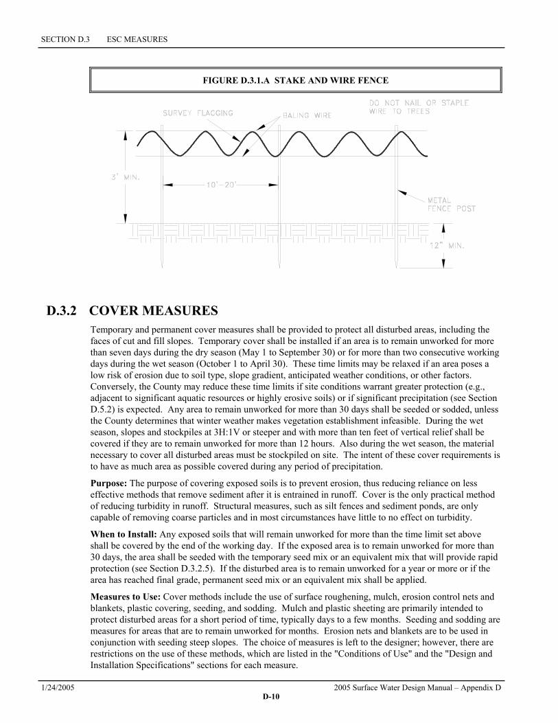
Measures to Use: Marking clearing limits by delineating the site with a continuous length of brightly colored survey tape is sometimes sufficient. The tape may be supported by vegetation or stakes, and it shall be 3 to 6 feet high and highly visible. Critical areas and their buffers require more substantial protection and shall be delineated with plastic or metal safety fences or stake and wire fences. Fencing may be required at the County's discretion to control construction traffic or at any location where greater protection is warranted. Permanent fencing may also be used if desired by the applicant. Silt fence, in combination with survey flagging, is also an acceptable method of marking critical areas and their buffers.
D.3.1.1 PLASTIC OR METAL FENCE
Code: FE Symbol:
Purpose Fencing is intended to (1) restrict clearing to approved limits; (2) prevent disturbance of critical areas, their buffers, and other areas required to be left undisturbed; (3) limit construction traffic to designated construction entrances or roads; and (4) protect areas where marking with survey tape may not provide adequate protection.
Conditions of Use To establish clearing limits, plastic or metal fence may be used:
1. At the boundary of critical areas, their buffers, and other areas required to be left uncleared.
2. As necessary to control vehicle access to and on the site (see Sections D.3.4.1 and D.3.4.2).

D.3.1 CLEARING LIMITS
2005 Surface Water Design Manual – Appendix D 1/24/2005 D-9
Design and Installation Specifications 1. The fence shall be designed and installed according to the manufacturer's specifications.
2. The fence shall be at least 3 feet high and must be highly visible.
3. The fence shall not be wired or stapled to trees.
Maintenance Requirements 1. If the fence has been damaged or visibility reduced, it shall be repaired or replaced immediately and
visibility restored.
2. Disturbance of a critical area, critical area buffer, native growth retention area, or any other area required to be left undisturbed shall be reported to the County for resolution.
D.3.1.2 STAKE AND WIRE FENCE
Code: SWF Symbol:
Purpose Fencing is intended to (1) restrict clearing to approved limits; (2) prevent disturbance of critical areas, their buffers, and other areas required to be left undisturbed; (3) limit construction traffic to designated construction entrances or roads; and (4) protect any areas where marking with survey tape may not provide adequate protection.
Conditions of Use To establish clearing limits, stake or wire fence may be used:
1. At the boundary of critical areas, their buffers, and other areas required to be left uncleared.
2. As necessary, to control vehicle access to and on the site (see Sections D.3.4.1 and D.3.4.2).
Design and Installation Specifications See Figure D.3.1.A for details.
Maintenance Requirements 1. If the fence has been damaged or visibility reduced, it shall be repaired or replaced immediately and
visibility restored.
2. Disturbance of a critical area, critical area buffer, native growth retention area, or other area required to be left undisturbed shall be reported to the County for resolution.
3. The County may require more substantial fencing if the fence does not prevent encroachment into those areas that are not to be disturbed.
SECTION D.3 ESC MEASURES
1/24/2005 2005 Surface Water Design Manual – Appendix D D-10
FIGURE D.3.1.A STAKE AND WIRE FENCE
D.3.2 COVER MEASURES Temporary and permanent cover measures shall be provided to protect all disturbed areas, including the faces of cut and fill slopes. Temporary cover shall be installed if an area is to remain unworked for more than seven days during the dry season (May 1 to September 30) or for more than two consecutive working days during the wet season (October 1 to April 30). These time limits may be relaxed if an area poses a low risk of erosion due to soil type, slope gradient, anticipated weather conditions, or other factors. Conversely, the County may reduce these time limits if site conditions warrant greater protection (e.g., adjacent to significant aquatic resources or highly erosive soils) or if significant precipitation (see Section D.5.2) is expected. Any area to remain unworked for more than 30 days shall be seeded or sodded, unless the County determines that winter weather makes vegetation establishment infeasible. During the wet season, slopes and stockpiles at 3H:1V or steeper and with more than ten feet of vertical relief shall be covered if they are to remain unworked for more than 12 hours. Also during the wet season, the material necessary to cover all disturbed areas must be stockpiled on site. The intent of these cover requirements is to have as much area as possible covered during any period of precipitation.
Purpose: The purpose of covering exposed soils is to prevent erosion, thus reducing reliance on less effective methods that remove sediment after it is entrained in runoff. Cover is the only practical method of reducing turbidity in runoff. Structural measures, such as silt fences and sediment ponds, are only capable of removing coarse particles and in most circumstances have little to no effect on turbidity.
When to Install: Any exposed soils that will remain unworked for more than the time limit set above shall be covered by the end of the working day. If the exposed area is to remain unworked for more than 30 days, the area shall be seeded with the temporary seed mix or an equivalent mix that will provide rapid protection (see Section D.3.2.5). If the disturbed area is to remain unworked for a year or more or if the area has reached final grade, permanent seed mix or an equivalent mix shall be applied.
Measures to Use: Cover methods include the use of surface roughening, mulch, erosion control nets and blankets, plastic covering, seeding, and sodding. Mulch and plastic sheeting are primarily intended to protect disturbed areas for a short period of time, typically days to a few months. Seeding and sodding are measures for areas that are to remain unworked for months. Erosion nets and blankets are to be used in conjunction with seeding steep slopes. The choice of measures is left to the designer; however, there are restrictions on the use of these methods, which are listed in the "Conditions of Use" and the "Design and Installation Specifications" sections for each measure.

D.3.2 COVER MEASURES
2005 Surface Water Design Manual – Appendix D 1/24/2005 D-11
The methods listed are by no means exhaustive. Variations on the standards presented here are encouraged if other cost-effective products or methods provide substantially equivalent or superior performance. Also, the details of installation can, and should, vary with the site conditions. A useful reference on the application of cover measures in the Puget Sound area is Horner, Guedrey, and Kortenhof (1990).
D.3.2.1 SURFACE ROUGHENING
Purpose The purpose of surface roughening is to aid in the establishment of vegetative cover and to reduce runoff velocity, increase infiltration, and provide for sediment trapping through the provision of a rough soil surface. The rough soil surface may be created by operating a tiller or other equipment on the contour to form horizontal depressions or by leaving slopes in a roughened condition by not fine grading.
Conditions of Use 1. All slopes steeper than 3:1 and greater than 5 vertical feet require surface roughening.
2. Areas with grades steeper than 3:1 should be roughened to a depth of 2 to 4 inches prior to seeding.
3. Areas that will not be stabilized immediately may be roughened to reduce runoff velocity until seeding takes place.
4. Slopes with a stable rock face do not require roughening.
5. Slopes where mowing is planned should not be excessively roughened.
Design and Installation Specifications There are different methods for achieving a roughened soil surface on a slope, and the selection of an appropriate method depends upon the type of slope. Roughening methods include stair-step grading, grooving, contour furrows, and tracking. See Figure D.3.2.A for information on tracking and contour furrows. Factors to be considered in choosing a method are slope steepness, mowing requirements, and whether the slope is formed by cutting or filling. Sole reliance on roughening for temporary erosion control is of limited effectiveness in intense rainfall events. Stair-step grading may not be practical for sandy, steep, or shallow soils.
1. Disturbed areas that will not require mowing may be stair-step graded, grooved, or left rough after filling
2. Stair Step grading is particularly appropriate in soils containing large amounts of soft rock. Each “step” catches material that sloughs from above, and provides a level site where vegetation can become established. Stairs should be wide enough to work with standard earth moving equipment. Stair steps must be on contour or gullies will form on the slope.
3. Areas that will be mowed (slopes less steep than 3:1) may have small furrows left by disking, harrowing, raking, or seed-planting machinery operated on the contour.
4. Graded areas with slopes greater than 3:1 but less than 2:1 should be roughened before seeding. This can be accomplished in a variety of ways, including “track walking” or driving a crawler tractor up and down the slope, leaving a pattern of cleat imprints parallel to slope contours.
5. Tracking is done by operating equipment up and down the slope to leave horizontal depressions in the soil.

SECTION D.3 ESC MEASURES
1/24/2005 2005 Surface Water Design Manual – Appendix D D-12
Maintenance Standards Periodically check roughened, seeded, planted, and mulched slopes for rills and gullies, particularly after a significant storm event. Fill these areas slightly above the original grade, then re-seed and mulch as soon as possible.
FIGURE D.3.2.A SURFACE ROUGHING

D.3.2 COVER MEASURES
2005 Surface Water Design Manual – Appendix D 1/24/2005 D-13
D.3.2.2 MULCHING
Code: MU Symbol:
Purpose The purpose of mulching soils is to provide immediate temporary protection from erosion. Mulch also enhances plant establishment by conserving moisture, holding fertilizer, seed, and topsoil in place, and moderating soil temperatures. There is an enormous variety of mulches that may be used. Only the most common types are discussed in this section.
Conditions of Use As a temporary cover measure, mulch should be used:
1. On disturbed areas that require cover measures for less than 30 days
2. As a cover for seed during the wet season and during the hot summer months
3. During the wet season on slopes steeper than 3H:1V with more than 10 feet of vertical relief.
Design and Installation Specifications For mulch materials, application rates, and specifications, see Table D.3.2.A. Note: Thicknesses may be increased for disturbed areas in or near critical areas or other areas highly susceptible to erosion.
Maintenance Standards 1. The thickness of the cover must be maintained.
2. Any areas that experience erosion shall be remulched and/or protected with a net or blanket. If the erosion problem is drainage related, then the drainage problem shall be assessed and alternate drainage such as interceptor swales may be needed to fix the problem and the eroded area remulched.

SECTION D.3 ESC MEASURES
1/24/2005 2005 Surface Water Design Manual – Appendix D D-14
TABLE D.3.2.A MULCH STANDARDS AND GUIDELINES
Mulch Material
Quality Standards Application Rates Remarks
Straw Air-dried; free from undesirable seed and coarse material
2"-3" thick; 2-3 bales per 1000 sf or 2-3 tons per acre
Cost-effective protection when applied with adequate thickness. Hand-application generally requires greater thickness than blown straw. Straw should be crimped to avoid wind blow. The thickness of straw may be reduced by half when used in conjunction with seeding.
Wood Fiber Cellulose
No growth inhibiting factors
Approx. 25-30 lbs per 1000 sf or 1000-1500 lbs per acre
Shall be applied with hydromulcher. Shall not be used without seed and tackifier unless the application rate is at least doubled. Some wood fiber with very long fibers can be effective at lower application rates and without seed or tackifier.
Compost No visible water or dust during handling. Must be purchased from supplier with Solid Waste Handling Permit.
2" thick min.; approx. 100 tons per acre (approx. 800 lbs per cubic yard)
More effective control can be obtained by increasing thickness to 3". Excellent mulch for protecting final grades until landscaping because it can be directly seeded or tilled into soil as an amendment. Sources for compost are available from the King County Commission for Marketing Recyclable Materials at (206) 296-4439. Compost may not be used in Sensitive Lake7 basins unless analysis of the compost shows no phosphorous release.
Hydraulic Matrices (Bonded Fiber Matrix)
This mulch category includes hydraulic slurries composed of wood fiber, paper fiber or a combination of the two held together by a binding system. The BFM shall be a mixture of long wood fibers and various bonding agents.
Apply at rates from 3,000 lbs per acre to 4,000 lbs per acre and based on manufacturers recommendations
The BFM shall not be applied immediately before, during or immediately after rainfall so that the matrix will have an opportunity to dry for 24 hours after installation. Application rates beyond 2,500 pounds may interfere with germination and are not usually recommended for turf establishment. BFM is generally a matrix where all fiber and binders are in one bag, rather than having to mix components from various manufacturers to create a matrix. BFMs can be installed via helicopter in remote areas. They are approximately $1,000 per acre cheaper to install.
Chipped Site Vegetation
Average size shall be several inches.
2" minimum thickness
This is a cost-effective way to dispose of debris from clearing and grubbing, and it eliminates the problems associated with burning. Generally, it should not be used on slopes above approx. 10% because of its tendency to be transported by runoff. It is not recommended within 200 feet of surface waters. If seeding is expected shortly after mulch, the decomposition of the chipped vegetation may tie up nutrients important to grass establishment.
7 Sensitive lake means a lake that has proved to be particularly prone to eutrophication; the County gives this designation when
an active input plan has been adopted to limit the amount of phosphorous entering the lake.

D.3.2 COVER MEASURES
2005 Surface Water Design Manual – Appendix D 1/24/2005 D-15
D.3.2.3 NETS AND BLANKETS
Code: NE Symbol:
Purpose Erosion control nets and blankets are intended to prevent erosion and hold seed and mulch in place on steep slopes and in channels so that vegetation can become well established. In addition, some nets and blankets can be used to permanently reinforce turf to protect drainage ways during high flows. Nets are strands of material woven into an open, but high-tensile strength net (for example, jute matting). Blankets are strands of material that are not tightly woven, but instead form a layer of interlocking fibers, typically held together by a biodegradable or photodegradable netting (for example, excelsior or straw blankets). They generally have lower tensile strength than nets, but cover the ground more completely. Coir (coconut fiber) fabric comes as both nets and blankets.
Conditions of Use Erosion control nets and blankets should be used:
1. For permanent stabilization of slopes 2H:1V or greater and with more than 10 feet of vertical relief.
2. In conjunction with seed for final stabilization of a slope, not for temporary cover. However, they may be used for temporary applications as long as the product is not damaged by repeated handling. In fact, this method of slope protection is superior to plastic sheeting, which generates high-velocity runoff (see Section D.3.2.4).
3. For drainage ditches and swales (highly recommended). The application of appropriate netting or blanket to drainage ditches and swales can protect bare soil from channelized runoff while vegetation is established. Nets and blankets also can capture a great deal of sediment due to their open, porous structure. Synthetic nets and blankets may be used to permanently stabilize channels and may provide a cost-effective, environmentally preferable alternative to riprap.
Design and Installation Specifications 1. See Figure D.3.2.B and Figure D.3.2.C for typical orientation and installation of nettings and
blankets. Note: Installation is critical to the effectiveness of these products. If good ground contact is not achieved, runoff can concentrate under the product, resulting in significant erosion.
2. With the variety of products available, it is impossible to cover all the details of appropriate use and installation. Therefore, it is critical that the design engineer thoroughly consults the manufacturer's information and that a site visit takes place in order to insure that the product specified is appropriate.
3. Jute matting must be used in conjunction with mulch (Section D.3.2.2). Excelsior, woven straw blankets, and coir (coconut fiber) blankets may be installed without mulch. There are many other types of erosion control nets and blankets on the market that may be appropriate in certain circumstances. Other types of products will have to be evaluated individually. In general, most nets (e.g., jute matting) require mulch in order to prevent erosion because they have a fairly open structure. Blankets typically do not require mulch because they usually provide complete protection of the surface.
4. Purely synthetic blankets are allowed but shall only be used for long-term stabilization of waterways. The organic blankets authorized above are better for slope protection and short-term waterway protection because they retain moisture and provide organic matter to the soil, substantially improving the speed and success of re-vegetation.

SECTION D.3 ESC MEASURES
1/24/2005 2005 Surface Water Design Manual – Appendix D D-16
Maintenance Standards 1. Good contact with the ground must be maintained, and there must not be erosion beneath the net or
blanket.
2. Any areas of the net or blanket that are damaged or not in close contact with the ground shall be repaired and stapled.
3. If erosion occurs due to poorly controlled drainage, the problem shall be fixed and the eroded area protected.
FIGURE D.3.2.B WATERWAY INSTALLATION
FIGURE D.3.2.C SLOPE INSTALLATION

D.3.2 COVER MEASURES
2005 Surface Water Design Manual – Appendix D 1/24/2005 D-17
D.3.2.4 PLASTIC COVERING
Code: PC Symbol:
Purpose Plastic covering provides immediate, short-term erosion protection to slopes and disturbed areas.
Conditions of Use 1. Plastic covering may be used on disturbed areas that require cover measures for less than 30 days.
2. Plastic is particularly useful for protecting cut and fill slopes and stockpiles. Note: The relatively rapid breakdown of most polyethylene sheeting makes it unsuitable for long-term applications.
3. Clear plastic sheeting may be used over newly-seeded areas to create a greenhouse effect and encourage grass growth. Clear plastic should not be used for this purpose during the summer months because the resulting high temperatures can kill the grass.
4. Due to rapid runoff caused by plastic sheeting, this method shall not be used upslope of areas that might be adversely impacted by concentrated runoff. Such areas include steep and/or unstable slopes.
Note: There have been many problems with plastic, usually attributable to poor installation and maintenance. However, the material itself can cause problems, even when correctly installed and maintained, because it generates high-velocity runoff and breaks down quickly due to ultraviolet radiation. In addition, if the plastic is not completely removed, it can clog drainage system inlets and outlets. It is highly recommended that alternatives to plastic sheeting be used whenever possible and that its use be limited.
Design and Installation Specifications 1. See Figure D.3.2.D for details.
2. Plastic sheeting shall have a minimum thickness of 0.06 millimeters.
3. If erosion at the toe of a slope is likely, a gravel berm, riprap, or other suitable protection shall be installed at the toe of the slope in order to reduce the velocity of runoff.
FIGURE D.3.2.D PLASTIC COVERING

SECTION D.3 ESC MEASURES
1/24/2005 2005 Surface Water Design Manual – Appendix D D-18
Maintenance Standards for Plastic Covering 1. Torn sheets must be replaced and open seams repaired.
2. If the plastic begins to deteriorate due to ultraviolet radiation, it must be completely removed and replaced.
3. When the plastic is no longer needed, it shall be completely removed.
D.3.2.5 STRAW WATTLES
Code: SW Symbol:
Purpose Wattles are erosion and sediment control barriers consisting of straw wrapped in biodegradable tubular plastic or similar encasing material. Wattles may reduce the velocity and can spread the flow of rill and sheet runoff, and can capture and retain sediment. Straw wattles are typically 8 to 10 inches in diameter and 25 to 30 feet in length. The wattles are placed in shallow trenches and staked along the contour of disturbed or newly constructed slopes.
Conditions of Use 1. Install on disturbed areas that require immediate erosion protection.
2. Use on slopes requiring stabilization until permanent vegetation can be established.
3. Can be used along the perimeter of a project, as a check dam in unlined ditches and around temporary stockpiles
4. Wattles can be staked to the ground using willow cuttings for added revegetation.
5. Rilling can occur beneath and between wattles if not properly entrenched, allowing water to pass below and between wattles
Design and Installation Specifications 1. It is critical that wattles are installed perpendicular to the flow direction and parallel to the slope
contour.
2. Narrow trenches should be dug across the slope, on contour, to a depth of 3 to 5 inches on clay soils and soils with gradual slopes. On loose soils, steep slopes, and during high rainfall events, the trenches should be dug to a depth of 5 to 7 inches, or ½ to 2/3 of the thickness of the wattle.
3. Start construction of trenches and installing wattles from the base of the slope and work uphill. Excavated material should be spread evenly along the uphill slope and compacted using hand tamping or other method. Construct trenches at contour intervals of 3 to 30 feet apart depending on the steepness of the slope, soil type, and rainfall. The steeper the slope the closer together the trenches should be constructed.
4. Install the wattles snugly into the trenches and abut tightly end to end. Do not overlap the ends.
5. Install stakes at each end of the wattle, and at 4 foot centers along the entire length of the wattle.
6. If required, install pilot holes for the stakes using a straight bar to drive holes through the wattle and into the soil.
7. At a minimum, wooden stakes should be approximately ¾ x ¾ x 24 inches. Willow cuttings or 3/8 inch rebar can also be used for stakes.

D.3.2 COVER MEASURES
2005 Surface Water Design Manual – Appendix D 1/24/2005 D-19
8. Stakes should be driven through the middle of the wattle, leaving 2 to 3 inches of the stake protruding above the wattle.
Maintenance Standards 1. Inspect wattles prior to forecasted rain, daily during extended rain events, after rain events, weekly
during the wet season, and at two week intervals at all other times of the year.
2. Repair or replace split, torn, raveling, or slumping wattles
3. Remove sediment accumulations when exceeding ½ the height between the top of the wattle and the ground surface.

SECTION D.3 ESC MEASURES
1/24/2005 2005 Surface Water Design Manual – Appendix D D-20
FIGURE D.3.2.E STRAW WATTLES

D.3.2 COVER MEASURES
2005 Surface Water Design Manual – Appendix D 1/24/2005 D-21
D.3.2.6 TEMPORARY AND PERMANENT SEEDING
Code: SE Symbol:
Purpose Seeding is intended to reduce erosion by stabilizing exposed soils. A well-established vegetative cover is one of the most effective methods of reducing erosion.
Conditions of Use 1. Seeding shall be used throughout the project on disturbed areas that have reached final grade or that
will remain unworked for more than 30 days.
2. Vegetation-lined channels shall be seeded. Channels that will be vegetated should be installed before major earthwork and hydroseeded or covered with a Bonded Fiber Matrix (BFM).
3. Retention/detention ponds shall be seeded as required.
4. At the County's discretion, seeding without mulch during the dry season is allowed even though it will take more than seven days to develop an effective cover. Mulch is, however, recommended at all times because it protects seeds from heat, moisture loss, and transport due to runoff.
5. At the beginning of the wet season, all disturbed areas shall be reviewed to identify which ones can be seeded in preparation for the winter rains (see Section D.5.2). Disturbed areas shall be seeded within one week of the beginning of the wet season. A sketch map of those areas to be seeded and those areas to remain uncovered shall be submitted to the DDES inspector. The DDES inspector may require seeding of additional areas in order to protect surface waters, adjacent properties, or drainage facilities.
6. At final site stabilization, all disturbed areas not otherwise vegetated or stabilized shall be seeded and mulched (see Section D.5.5).
Design and Installation Specifications 1. The best time to seed is April 1 through June 30, and September 1 through October 15. Areas may be
seeded between July 1 and August 31, but irrigation may be required in order to grow adequate cover. Areas may also be seeded during the winter months, but it may take several months to develop a dense groundcover due to cold temperatures. The application and maintenance of mulch is critical for winter seeding.
2. To prevent seed from being washed away, confirm that all required surface water control measures have been installed.
3. The seedbed should be firm but not compacted because soils that are well compacted will not vegetate as quickly or thoroughly. Slopes steeper than 3H:1V shall be surface roughened. Roughening can be accomplished in a variety of ways, but the typical method is track walking, or driving a crawling tractor up and down the slope, leaving cleat imprints parallel to the slope contours.
4. In general, 10-20-20 N-P-K (nitrogen-phosphorus-potassium) fertilizer may be used at a rate of 90 pounds per acre. Slow-release fertilizers are preferred because they are more efficient and have fewer environmental impacts. It is recommended that areas being seeded for final landscaping conduct soil tests to determine the exact type and quantity of fertilizer needed. This will prevent the over-application of fertilizer. Disturbed areas within 200 feet of water bodies and wetlands must use slow-release low-phosphorus fertilizer (typical proportions 3-1-2 N-P-K).
5. The following requirements apply to mulching:
a) Mulch is always required for seeding slopes greater than 3H:1V (see Section D.4.2.1).

SECTION D.3 ESC MEASURES
1/24/2005 2005 Surface Water Design Manual – Appendix D D-22
b) If seeding during the wet season, mulch is required.
c) The use of mulch may be required during the dry season at the County's discretion if grass growth is expected to be slow, the soils are highly erodible due to soil type or gradient, there is a water body close to the disturbed area, or significant precipitation (see Section D.5.2) is anticipated before the grass will provide effective cover.
d) Mulch may be applied on top of the seed or simultaneously by hydroseeding.
6. Hydroseeding is allowed as long as tackifier is included. Hydroseeding with wood fiber mulch is adequate during the dry season. During the wet season, the application rate shall be doubled because the mulch and tackifier used in hydroseeding break down fairly rapidly. It may be necessary in some applications to include straw with the wood fiber, but this can be detrimental to germination.
7. Areas to be permanently landscaped shall use soil amendments. Good quality topsoil shall be tilled into the top six inches to reduce the need for fertilizer and improve the overall soil quality. Most native soils will require the addition of four inches of well-rotted compost to be tilled into the soil to provide a good quality topsoil. Compost used should meet Ecology publication 98-38 specifications for Grade A quality compost.
8. The seed mixes listed below include recommended mixes for both temporary and permanent seeding. These mixes, with the exception of the wetland mix, shall be applied at a rate of 120 pounds per acre. This rate may be reduced if soil amendments or slow-release fertilizers are used. Local suppliers should be consulted for their recommendations because the appropriate mix depends on a variety of factors, including exposure, soil type, slope, and expected foot traffic. Alternative seed mixes approved by the County may be used.
Table D.3.2.B presents the standard mix for those areas where just a temporary vegetative cover is required.
TABLE D.3.2.BTEMPORARY EROSION CONTROL SEED MIX
% Weight % Purity % Germination
Chewings or red fescue Festuca rubra var. commutata or Festuca rubra
40 98 90
Annual or perennial rye Lolium multiflorum or Lolium perenne
40 98 90
Redtop or colonial bentgrass Agrostis alba or Agrostis tenuis
10 92 85
White dutch clover Trifolium repens
10 98 90

D.3.2 COVER MEASURES
2005 Surface Water Design Manual – Appendix D 1/24/2005 D-23
Table D.3.2.C provides just one recommended possibility for landscaping seed.
TABLE D.3.2.C LANDSCAPING SEED MIX
% Weight % Purity % Germination
Perennial rye blend Lolium perenne
70 98 90
Chewings and red fescue blend Festuca rubra var. commutata or Festuca rubra
30 98 90
This turf seed mix in Table D.3.2.D is for dry situations where there is no need for much water. The advantage is that this mix requires very little maintenance.
TABLE D.3.2.D LOW-GROWING TURF SEED MIX
% Weight % Purity % Germination
Dwarf tall fescue (several varieties) Festuca arundinacea var.
45 98 90
Dwarf perennial rye (Barclay) Lolium perenne var. barclay
30 98 90
Red fescue Festuca rubra
20 98 90
Colonial bentgrass Agrostis tenuis
5 98 90
Table D.3.2.E presents a mix recommended for bioswales and other intermittently wet areas. Sod shall generally not be used for bioswales because the seed mix is inappropriate for this application. Sod may be used for lining ditches to prevent erosion, but it will provide little water quality benefit during the wet season.
TABLE D.3.2.E BIOSWALE SEED MIX*
% Weight % Purity % Germination
Tall or meadow fescue Festuca arundinacea or Festuca elatior
75-80 98 90
Seaside/Creeping bentgrass Agrostis palustris
10-15 92 85
Redtop bentgrass Agrostis alba or Agrostis gigantea
5-10 90 80
* Modified Briargreen, Inc. Hydroseeding Guide Wetlands Seed Mix

SECTION D.3 ESC MEASURES
1/24/2005 2005 Surface Water Design Manual – Appendix D D-24
The seed mix shown in Table D.3.2.F is a recommended low-growing, relatively non-invasive seed mix appropriate for very wet areas that are not regulated wetlands (if planting in wetland areas, see Section 6.3.1 of the Surface Water Design Manual). Other mixes may be appropriate, depending on the soil type and hydrology of the area. Apply this mixture at a rate of 60 pounds per acre.
TABLE D.3.2.F WET AREA SEED MIX*
% Weight % Purity % Germination
Tall or meadow fescue Festuca arundinacea or Festuca elatior
60-70 98 90
Seaside/Creeping bentgrass Agrostis palustris
10-15 98 85
Meadow foxtail Alepocurus pratensis
10-15 90 80
Alsike clover Trifolium hybridum
1-6 98 90
Redtop bentgrass Agrostis alba
1-6 92 85
* Modified Briargreen, Inc. Hydroseeding Guide Wetlands Seed Mix
The meadow seed mix in Table D.3.2.G is recommended for areas that will be maintained infrequently or not at all and where colonization by native plants is desirable. Likely applications include rural road and utility right-of-way. Seeding should take place in September or very early October in order to obtain adequate establishment prior to the winter months. The appropriateness of clover in the mix may need to be considered as this can be a fairly invasive species. If the soil is amended, the addition of clover may not be necessary.
TABLE D.3.2.G MEADOW SEED MIX
% Weight % Purity % Germination
Redtop or Oregon bentgrass Agrostis alba or Agrostis oregonensis
40 92 85
Red fescue Festuca rubra
40 98 90
White dutch clover Trifolium repens
20 98 90
Maintenance Standards for Temporary and Permanent Seeding 1. Any seeded areas that fail to establish at least 80 percent cover within one month shall be reseeded. If
reseeding is ineffective, an alternate method, such as sodding or nets/blankets, shall be used. If winter weather prevents adequate grass growth, this time limit may be relaxed at the discretion of the County when critical areas would otherwise be protected.

D.3.2 COVER MEASURES
2005 Surface Water Design Manual – Appendix D 1/24/2005 D-25
2. After adequate cover is achieved, any areas that experience erosion shall be re-seeded and protected by mulch. If the erosion problem is drainage related, the problem shall be fixed and the eroded area re-seeded and protected by mulch.
3. Seeded areas shall be supplied with adequate moisture, but not watered to the extent that it causes runoff.
D.3.2.7 SODDING
Code: SO Symbol:
Purpose The purpose of sodding is to establish permanent turf for immediate erosion protection and to stabilize drainage ways where concentrated overland flow will occur.
Conditions of Use Sodding may be used in the following areas:
1. Disturbed areas that require short-term or long-term cover
2. Disturbed areas that require immediate vegetative cover
3. All waterways that require vegetative lining (except biofiltration swales—the seed mix used in most sod is not appropriate for biofiltration swales). Waterways may also be seeded rather than sodded, and protected with a net or blanket (see Section D.3.2.3).
Design and Installation Specifications Sod shall be free of weeds, of uniform thickness (approximately 1-inch thick), and shall have a dense root mat for mechanical strength.
The following steps are recommended for sod installation:
1. Shape and smooth the surface to final grade in accordance with the approved grading plan.
2. Amend two inches (minimum) of well-rotted compost into the top six inches of the soil if the organic content of the soil is less than ten percent. Compost used should meet Ecology publication 98-38 specifications for Grade A quality compost.
3. Fertilize according to the supplier's recommendations. Disturbed areas within 200 feet of water bodies and wetlands must use non-phosphorus fertilizer.
4. Work lime and fertilizer 1 to 2 inches into the soil, and smooth the surface.
5. Lay strips of sod beginning at the lowest area to be sodded and perpendicular to the direction of water flow. Wedge strips securely into place. Square the ends of each strip to provide for a close, tight fit. Stagger joints at least 12 inches. Staple on slopes steeper than 3H:1V.
6. Roll the sodded area and irrigate.
7. When sodding is carried out in alternating strips or other patterns, seed the areas between the sod immediately after sodding.
Maintenance Standards If the grass is unhealthy, the cause shall be determined and appropriate action taken to reestablish a healthy groundcover. If it is impossible to establish a healthy groundcover due to frequent saturation, instability, or some other cause, the sod shall be removed, the area seeded with an appropriate mix, and protected with a net or blanket.

SECTION D.3 ESC MEASURES
1/24/2005 2005 Surface Water Design Manual – Appendix D D-26
D.3.2.8 POLYACRYLAMIDE FOR SOIL EROSION PROTECTION
Purpose Polyacrylamide (PAM) is used on construction sites to prevent soil erosion. Applying PAM to bare soil in advance of a rain event significantly reduces erosion and controls sediment in two ways. First, PAM increases the soil’s available pore volume, thus increasing infiltration through flocculation and reducing the quantity of stormwater runoff. Second, it increases flocculation of suspended particles and aids in their deposition, thus reducing stormwater runoff turbidity and improving water quality.
Conditions of Use 1. PAM shall not be directly applied to water or allowed to enter a water body.
2. PAM may be applied to wet soil, but dry soil is preferred due to less sediment loss.
3. PAM will work when applied to saturated soil but is not as effective as applications to dry or damp soil.
4. PAM may be applied only to the following types of bare soil areas that drain to a sediment trap or a sediment pond:
• Staging areas
• Stockpiles
• Pit sites
• Balanced cut and fill earthwork
• Haul roads prior to placement of crushed rock surfacing
• Compacted soil road base
5. PAM may be applied only during the following phases of construction:
• During rough grading operations
• After final grade and before paving or final seeding and planting
• During a winter shut down of site work. In the case of winter shut down, or where soil will remain unworked for several months, PAM should be used together with mulch.
6. Do not use PAM on a slope that flows directly to a stream or wetland. The stormwater runoff shall pass through a sediment control measure prior to discharging to surface waters.
Design and Installation Specifications 1. PAM must be applied using one of two methods of application, "preferred" or "alternative." The
specifications for these methods are described under separate headings below.
2. PAM may be applied in dissolved form with water, or it may be applied in dry, granular or powdered form. The preferred application method is the dissolved form.
3. PAM is to be applied at a maximum rate of ½ pound PAM per 1000 gallons of water per 1 acre of bare soil. Table D.3.2.H may be used to determine the PAM and water application rate for disturbed soil areas. Higher concentrations of PAM do not provide any additional effectiveness.
4. Do not add PAM to water discharging from the site.
5. PAM shall be used in conjunction with other ESC measures and not in place of them. When the total drainage area is greater than or equal to 3 acres, PAM treated areas shall drain to a sediment pond per Section D.3.5.2. For drainage areas less than 3 acres, PAM treated areas must drain to a sediment trap per Section D.3.5.1. Other normally required sediment control measures such as perimeter protection

D.3.2 COVER MEASURES
2005 Surface Water Design Manual – Appendix D 1/24/2005 D-27
measures (Section D.3.3) and surface water collection measures (Section D.3.6) shall be applied to PAM treated areas.
6. All areas not being actively worked shall be covered and protected from rainfall. PAM shall not be the only cover BMP used.
7. Keep the granular PAM supply out of the sun. Granular PAM loses its effectiveness in three months after exposure to sunlight and air.
8. Care must be taken to prevent spills of PAM powder onto paved surfaces. PAM, combined with water, is very slippery and can be a safety hazard. During an application of PAM, prevent over-spray from reaching pavement as the pavement will become slippery. If PAM powder gets on skin or clothing, wipe it off with a rough towel rather than washing with water. Washing with water only makes cleanup more difficult, messier, and time consuming.
9. The specific PAM copolymer formulation must be anionic. Cationic PAM shall not be used in any application because of known aquatic toxicity concerns. Only the highest drinking water grade PAM, certified for compliance with ANSI/NSF Standard 60 for drinking water treatment, may be used for soil applications. The Washington State Department of Transportation (WSDOT) lists approved PAM products on their web page. All PAM use shall be reviewed and approved by DDES.
10. The PAM anionic charge density may vary from 2 – 30 percent; a value of 18 percent is typical. Studies conducted by the United States department of Agriculture (USDA)/ARS demonstrated that soil stabilization was optimized by using very high molecular weight (12 – 15 mg/mole), highly anionic (>20% hydrolysis) PAM.
11. PAM must be "water soluble" or "linear" or "non-cross-linked." Cross-linked or water absorbent PAM, polymerized in highly acidic (pH<2) conditions, are used to maintain soil moisture content.
TABLE D.3.2.H PAM AND WATER APPLICATION RATES
Disturbed Area (ac) PAM (lbs) Water (gal) 0.50 0.25 500 1.00 0.50 1,000 1.50 0.75 1,500 2.00 1.00 2,000 2.50 1.25 2,500 3.00 1.50 3,000 3.50 1.75 3,500 4.00 2.00 4,000 4.50 2.25 4,500 5.00 2.50 5,000
Preferred Application Method 1. Pre-measure the area where PAM is to be applied and calculate the amount of product and water
necessary to provide coverage at the specified application rate (1/2 pound PAM/1,000 gallons/acre).
2. Dissolve pre-measured dry granular PAM with a known quantity of clean water in a bucket several hours or overnight. PAM has infinite solubility in water, but dissolves very slowly. Mechanical mixing will help dissolve PAM. Always add PAM to water – not water to PAM.
3. Pre-fill the water truck about 1/8 full with water. The water does not have to be potable, but it must have relatively low turbidity – in the range of 20 NTU or less.

SECTION D.3 ESC MEASURES
1/24/2005 2005 Surface Water Design Manual – Appendix D D-28
4. Add PAM/Water mixture to the truck.
5. Completely fill the water truck to specified volume.
6. Spray PAM/Water mixture onto dry soil until the soil surface is uniformly and completely wetted.
Alternate Application Method PAM may also be applied as a powder at the rate of 5 pounds per acre. This must be applied on a day that is dry. For areas less than 5-10 acres, a hand-held “organ grinder” fertilized spreader set to the smallest setting will work. Tractor mounted spreaders will work for larger areas.
Maintenance Standards 1. PAM may be reapplied on actively worked areas after a 48-hour period
2. Reapplication is not required unless PAM treated soil is disturbed or unless turbidity levels show the need for an additional application. If PAM treated soil is left undisturbed, a reapplication may be necessary after two months. More PAM applications may be required for steep slopes, silty and clay soils, (USDA classification Type "C" and "D" soils), long grades, and high precipitation areas. When PAM is applied first to bare soil and then covered with straw, a reapplication may not be necessary for several months.
D.3.2.9 COMPOST BLANKETS
Code: COBL Symbol:
Purpose Compost blankets are intended to:
• Provide immediate temporary protection from erosion by protecting soil from rainfall and slowing flow velocity over the soil surface.
• Enhance temporary or permanent plant establishment by conserving moisture, holding seed and topsoil in place, providing nutrients and soil microorganisms, and moderating soil temperatures.
• Compost blankets, applied at the proper thickness and tilled into the soil, are also an option for amending soils for permanent landscaping.
• Compost generally releases and adds phosphorous to stormwater. Therefore, compost blankets are not recommended for use in watersheds where phosphorous sensitive water resources are located. Unless prior approval is given by the County, they should not be used in Sensitive Lake Watersheds.
Conditions of Use 1. Compost blankets may be used unseeded on disturbed areas that require temporary cover measures up
to 1 year. Compost applied as temporary cover may be reclaimed and re-used for permanent cover.
2. Compost provides cover for protecting final grades until landscaping can be completed as it can be directly seeded or tilled into soil as an amendment.
3. Compost blankets meet mulch requirements for seed.
4. Seed may be applied to a compost blanket at any time for permanent or temporary stabilization of disturbed areas. Seed may be applied prior to blanket application, on top of blankets, or injected and mixed into the compost as it is applied.
5. Compost blankets may be applied on slopes up to 2H:1V.

D.3.2 COVER MEASURES
2005 Surface Water Design Manual – Appendix D 1/24/2005 D-29
Design and Installation Specifications 1. Compost shall be applied at a minimum of 2 inches thick, unless otherwise directed by an ESC
supervisor or King County. At an application of 2 inches, this will equal approximately 100 tons per acre (compost generally weighs approximately 800 lbs per cubic yard). Thickness shall be increased at the direction of the design engineer for disturbed areas in or near critical areas or other areas highly susceptible to erosion.
2. Compost shall meet criteria in WAC 173-350-220 (10) for Designation of Composted Materials.
3. Compost shall be obtained from a supplier meeting the requirements of WAC 173-350-220.
4. Compost blankets shall be applied over the top of the slope to which it is applied, to prevent water from running under the blanket
5. Compost blankets shall not be used in areas exposed to concentrated flow (e.g. channels, ditches, dikes)
Maintenance Standards 1. The specified thickness of the blanket/cover must be maintained.
2. Any areas that show signs of erosion must be re-mulched. If the erosion problem is drainage related, then the drainage problem must first be remedied and then the eroded area re-mulched.
SECTION D.3 ESC MEASURES
1/24/2005 2005 Surface Water Design Manual – Appendix D D-30
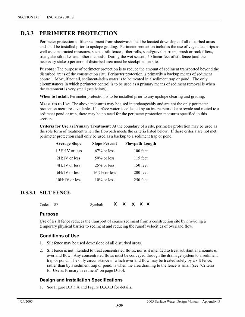
D.3.3 PERIMETER PROTECTION Perimeter protection to filter sediment from sheetwash shall be located downslope of all disturbed areas and shall be installed prior to upslope grading. Perimeter protection includes the use of vegetated strips as well as, constructed measures, such as silt fences, fiber rolls, sand/gravel barriers, brush or rock filters, triangular silt dikes and other methods. During the wet season, 50 linear feet of silt fence (and the necessary stakes) per acre of disturbed area must be stockpiled on site.
Purpose: The purpose of perimeter protection is to reduce the amount of sediment transported beyond the disturbed areas of the construction site. Perimeter protection is primarily a backup means of sediment control. Most, if not all, sediment-laden water is to be treated in a sediment trap or pond. The only circumstances in which perimeter control is to be used as a primary means of sediment removal is when the catchment is very small (see below).
When to Install: Perimeter protection is to be installed prior to any upslope clearing and grading.
Measures to Use: The above measures may be used interchangeably and are not the only perimeter protection measures available. If surface water is collected by an interceptor dike or swale and routed to a sediment pond or trap, there may be no need for the perimeter protection measures specified in this section.
Criteria for Use as Primary Treatment: At the boundary of a site, perimeter protection may be used as the sole form of treatment when the flowpath meets the criteria listed below. If these criteria are not met, perimeter protection shall only be used as a backup to a sediment trap or pond.
Average Slope Slope Percent Flowpath Length
1.5H:1V or less 67% or less 100 feet
2H:1V or less 50% or less 115 feet
4H:1V or less 25% or less 150 feet
6H:1V or less 16.7% or less 200 feet
10H:1V or less 10% or less 250 feet
D.3.3.1 SILT FENCE Code: SF Symbol:
Purpose Use of a silt fence reduces the transport of coarse sediment from a construction site by providing a temporary physical barrier to sediment and reducing the runoff velocities of overland flow.
Conditions of Use 1. Silt fence may be used downslope of all disturbed areas.
2. Silt fence is not intended to treat concentrated flows, nor is it intended to treat substantial amounts of overland flow. Any concentrated flows must be conveyed through the drainage system to a sediment trap or pond. The only circumstance in which overland flow may be treated solely by a silt fence, rather than by a sediment trap or pond, is when the area draining to the fence is small (see "Criteria for Use as Primary Treatment" on page D-30).
Design and Installation Specifications 1. See Figure D.3.3.A and Figure D.3.3.B for details.

D.3.3 PERIMETER PROTECTION
2005 Surface Water Design Manual – Appendix D 1/24/2005 D-31
2. The geotextile used must meet the standards listed below. A copy of the manufacturer's fabric specifications must be available on site.
AOS (ASTM D4751) 30-100 sieve size (0.60-0.15 mm) for slit film 50-100 sieve size (0.30-0.15 mm) for other fabrics
Water Permittivity (ASTM D4491) 0.02 sec-1 minimum
Grab Tensile Strength (ASTM D4632) 180 lbs. min. for extra strength fabric 100 lbs. min. for standard strength fabric
Grab Tensile Elongation (ASTM D4632) 30% max.
Ultraviolet Resistance (ASTM D4355) 70% min.
3. Standard strength fabric requires wire backing to increase the strength of the fence. Wire backing or closer post spacing may be required for extra strength fabric if field performance warrants a stronger fence.
4. Where the fence is installed, the slope shall be no steeper than 2H:1V.
5. If a typical silt fence (per Figure D.3.3.A) is used, the standard 4 x 4 trench may not be reduced as long as the bottom 8 inches of the silt fence is well buried and secured in a trench that stabilizes the fence and does not allow water to bypass or undermine the silt fence.
Maintenance Standards 1. Any damage shall be repaired immediately.
2. If concentrated flows are evident uphill of the fence, they must be intercepted and conveyed to a sediment trap or pond.
3. It is important to check the uphill side of the fence for signs of the fence clogging and acting as a barrier to flow and then causing channelization of flows parallel to the fence. If this occurs, replace the fence or remove the trapped sediment.
4. Sediment must be removed when the sediment is 6 inches high.
5. If the filter fabric (geotextile) has deteriorated due to ultraviolet breakdown, it shall be replaced.
FIGURE D.3.3.A SILT FENCE

SECTION D.3 ESC MEASURES
1/24/2005 2005 Surface Water Design Manual – Appendix D D-32
FIGURE D.3.3.B SILT FENCE INSTALLATION BY SLICING

D.3.3 PERIMETER PROTECTION
2005 Surface Water Design Manual – Appendix D 1/24/2005 D-33
D.3.3.2 BRUSH BARRIER
Code: BB Symbol:
Purpose The purpose of brush barriers is to reduce the transport of coarse sediment from a construction site by providing a temporary physical barrier to sediment and reducing the runoff velocities of overland flow.
Conditions of Use 1. Brush barriers may be used downslope of all disturbed areas.
2. Brush barriers are not intended to treat concentrated flows, nor are they intended to treat substantial amounts of overland flow. Any concentrated flows must be conveyed through the drainage system to a sediment trap or pond. The only circumstance in which overland flow may be treated solely by a barrier, rather than by a sediment trap or pond, is when the area draining to the barrier is small (see "Criteria for Use as Primary Treatment" on page D-30).
Design and Installation Specifications 1. See Figure D.3.3.C for details.
2. King County may require filter fabric (geotextile) anchored over the brush berm to enhance the filtration ability of the barrier.
Maintenance Standards 1. There shall be no signs of erosion or concentrated runoff under or around the barrier. If concentrated
flows are bypassing the barrier, it must be expanded or augmented by toed-in filter fabric.
2. The dimensions of the barrier must be maintained.
FIGURE D.3.3.C BRUSH BARRIER

SECTION D.3 ESC MEASURES
1/24/2005 2005 Surface Water Design Manual – Appendix D D-34
D.3.3.3 VEGETATED STRIP
Code: VS Symbol:
Purpose Vegetated strips reduce the transport of coarse sediment from a construction site by providing a temporary physical barrier to sediment and reducing the runoff velocities of overland flow.
Conditions of Use 1. Vegetated strips may be used downslope of all disturbed areas.
2. Vegetated strips are not intended to treat concentrated flows, nor are they intended to treat substantial amounts of overland flow. Any concentrated flows must be conveyed through the drainage system to a sediment trap or pond. The only circumstance in which overland flow may be treated solely by a strip, rather than by a sediment trap or pond, is when the area draining to the strip is small (see "Criteria for Use as Primary Treatment" on page D-30).
Design and Installation Specifications 1. The vegetated strip shall consist of a 25-foot minimum width continuous strip of dense vegetation
with a permeable topsoil. Grass-covered, landscaped areas are generally not adequate because the volume of sediment overwhelms the grass. Ideally, vegetated strips shall consist of undisturbed native growth with a well-developed soil that allows for infiltration of runoff.
2. The slope within the strip shall not exceed 4H:1V.
3. The uphill boundary of the vegetated strip shall be delineated with clearing limits as specified in Section D.3.1 (p. D-8).
Maintenance Standards 1. Any areas damaged by erosion or construction activity shall be seeded immediately and protected by
mulch.
2. If more than 5 feet of the original vegetated strip width has had vegetation removed or is being eroded, sod must be installed using the standards for installation found in Section D.4.2.5.
If there are indications that concentrated flows are traveling across the buffer, surface water controls must be installed to reduce the flows entering the buffer, or additional perimeter protection must be installed.
D.3.3.4 TRIANGULAR SILT DIKE (GEOTEXTILE ENCASED CHECK DAM)
Code: TSD Symbol:
Purpose Triangular silt dikes (TSDs) may be used as check dams, for perimeter protection, for temporary soil stockpile protection, for drop inlet protection, or as a temporary interceptor dike. Silt dikes, if attached to impervious surfaces with tack or other adhesive agent may also be used as temporary wheel wash areas, or concrete washout collection areas.
Conditions of Use 1. May be used for temporary check dams in ditches.

D.3.3 PERIMETER PROTECTION
2005 Surface Water Design Manual – Appendix D 1/24/2005 D-35
2. May be used on soil or pavement with adhesive or staples.
3. TSDs have been used to build temporary sediment ponds, diversion ditches, concrete washout facilities, curbing, water bars, level spreaders, and berms.
Design and Installation Specifications 1. TSDs must be made of urethane foam sewn into a woven geosynthetic fabric.
2. TSDs are triangular, 10 inches to 14 inches high in the center, with a 20-inch to 28-inch base. A 2-foot apron extends beyond both sides of the triangle along its standard section of 7 feet. A sleeve at one end allows attachment of additional sections as needed
3. Install TSDs with ends curved up to prevent water from flowing around the ends
4. Attach the TSDs and their fabric flaps to the ground with wire staples. Wire staples must be No. 11 gauge wire or stronger and shall be 200 mm to 300 mm in length.
5. When multiple units are installed, the sleeve of fabric at the end of the unit shall overlap the abutting unit and be stapled.
6. TSDs must be located and installed as soon as construction will allow.
7. TSDs must be placed perpendicular to the flow of water.
8. When used as check dams, the leading edge must be secured with rocks, sandbags, or a small key slot and staples.
9. When used in grass-lined ditches and swales, the TSD check dams and accumulated sediment shall be removed when the grass has matured sufficiently to protect the ditch or swale unless the slope of the swale is greater than 4 percent. The area beneath the TSD check dams shall be seeded and mulched immediately after dam removal.
Maintenance Standards 1. Triangular silt dikes shall be monitored for performance and sediment accumulation during and after
each runoff producing rainfall event. Sediment shall be removed when it reaches one half the height of the silt dike.
2. Anticipate submergence and deposition above the triangular silt dike and erosion from high flows around the edges of the dike/dam. Immediately repair any damage or any undercutting of the dike/dam.
D.3.3.5 COMPOST BERMS
Code: COBE Symbol:
Purpose Compost berms are an option to meet the requirements of perimeter protection. Compost berms may reduce the transport of sediment from a construction site by providing a temporary physical barrier to sediment and reducing the runoff velocities of overland flow. Compost berms trap sediment by filtering water passing through the berm and allowing water to pond, creating a settling area for solids behind the berm. Organic materials in the compost can also reduce concentrations of metals and petroleum hydrocarbons from construction runoff. Due to the increase in phosphorous seen in the effluent data from compost berms, they should be used with some cautions in areas that drain to phosphorus sensitive water bodies, and should only be used in Sensitive Lake watersheds, such as Lake Sammamish, with the approval from the County or the local jurisdiction.
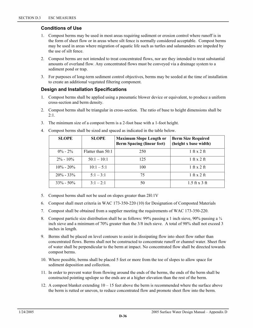
SECTION D.3 ESC MEASURES
1/24/2005 2005 Surface Water Design Manual – Appendix D D-36
Conditions of Use 1. Compost berms may be used in most areas requiring sediment or erosion control where runoff is in
the form of sheet flow or in areas where silt fence is normally considered acceptable. Compost berms may be used in areas where migration of aquatic life such as turtles and salamanders are impeded by the use of silt fence.
2. Compost berms are not intended to treat concentrated flows, nor are they intended to treat substantial amounts of overland flow. Any concentrated flows must be conveyed via a drainage system to a sediment pond or trap.
3. For purposes of long-term sediment control objectives, berms may be seeded at the time of installation to create an additional vegetated filtering component.
Design and Installation Specifications 1. Compost berms shall be applied using a pneumatic blower device or equivalent, to produce a uniform
cross-section and berm density.
2. Compost berms shall be triangular in cross-section. The ratio of base to height dimensions shall be 2:1.
3. The minimum size of a compost berm is a 2-foot base with a 1-foot height.
4. Compost berms shall be sized and spaced as indicated in the table below.
SLOPE SLOPE Maximum Slope Length or Berm Spacing (linear feet)
Berm Size Required (height x base width)
0% - 2% Flatter than 50:1 250 1 ft x 2 ft
2% - 10% 50:1 – 10:1 125 1 ft x 2 ft
10% - 20% 10:1 – 5:1 100 1 ft x 2 ft
20% - 33% 5:1 – 3:1 75 1 ft x 2 ft
33% - 50% 3:1 – 2:1 50 1.5 ft x 3 ft
5. Compost berms shall not be used on slopes greater than 2H:1V
6. Compost shall meet criteria in WAC 173-350-220 (10) for Designation of Composted Materials
7. Compost shall be obtained from a supplier meeting the requirements of WAC 173-350-220.
8. Compost particle size distribution shall be as follows: 99% passing a 1 inch sieve, 90% passing a ¾ inch sieve and a minimum of 70% greater than the 3/8 inch sieve. A total of 98% shall not exceed 3 inches in length.
9. Berms shall be placed on level contours to assist in dissipating flow into sheet flow rather than concentrated flows. Berms shall not be constructed to concentrate runoff or channel water. Sheet flow of water shall be perpendicular to the berm at impact. No concentrated flow shall be directed towards compost berms.
10. Where possible, berms shall be placed 5 feet or more from the toe of slopes to allow space for sediment deposition and collection.
11. In order to prevent water from flowing around the ends of the berms, the ends of the berm shall be constructed pointing upslope so the ends are at a higher elevation than the rest of the berm.
12. A compost blanket extending 10 – 15 feet above the berm is recommended where the surface above the berm is rutted or uneven, to reduce concentrated flow and promote sheet flow into the berm.

D.3.3 PERIMETER PROTECTION
2005 Surface Water Design Manual – Appendix D 1/24/2005 D-37
Maintenance Standards 1. Compost berms shall be regularly inspected to make sure they retain their shape and allow adequate
flow-through of stormwater.
2. When construction is completed on site, the berms shall be dispersed for incorporation into the soil or left on top of the site for final seeding to occur.
3. Any damage to berms must be repaired immediately. Damage includes flattening, compacting, rills, eroded areas due to overtopping.
4. If concentrated flows are evident uphill of the berm, the flows must be intercepted and conveyed to a sediment trap or pond.
5. The uphill side of the berm shall be inspected for signs of the berm clogging and acting as a barrier to flows and causing channelization of flows parallel to the berm. If this occurs, replace the berm or remove the trapped sediment.
6. Sediment that collects behind the berm must be removed when the sediment is more than 6 inches deep.
D.3.3.6 COMPOST SOCKS
Code: COSO Symbol:
Purpose Compost socks reduce the transport of sediment from a construction site by providing a temporary physical barrier to sediment-laden water and reducing the runoff velocities of overland flow. Compost socks trap sediment by filtering water that passes through the sock and allows water to pond behind the sock, creating a settling area for solids. Organic materials in the compost also may reduce metal and petroleum hydrocarbon concentrations in construction runoff. Compost socks function similarly to compost berms; however, because the compost is contained in a mesh tube, they are appropriate for both concentrated flow and sheet flow. Compost socks may be used to channel concentrated flow on hard surfaces.
Conditions of Use 1. Compost socks may be used in areas requiring sediment or erosion control where runoff is in the form
of sheet flow or in areas that silt fence is normally considered acceptable. Compost socks may also be used in sensitive environmental areas where migration of aquatic life, including turtles, salamanders and other aquatic life may be impeded by the used of silt fence.
2. Compost socks are not intended to treat substantial amounts of overland flow. However, compost socks may be subjected to some ponding and concentrated flows. If intended primarily as a filtration device, the socks should be sized and placed so that flows do not overtop the socks.
3. For purposes of long term sediment control objectives, compost socks may be seeded at the time of installation to create an additional vegetated filtering component.
Design and Installation Specifications 1. Compost socks shall be produced using a pneumatic blower hose or equivalent to fill a mesh tube
with compost to create a uniform cross-section and berm density.
2. Socks shall be filled so they are firmly – packed yet flexible. Upon initial filling, the socks shall be filled to have a round cross-section. Once placed on the ground, it is recommended to apply weight to the sock to improve contact with the underlying surface. This may cause the sock to assume an oval shape.
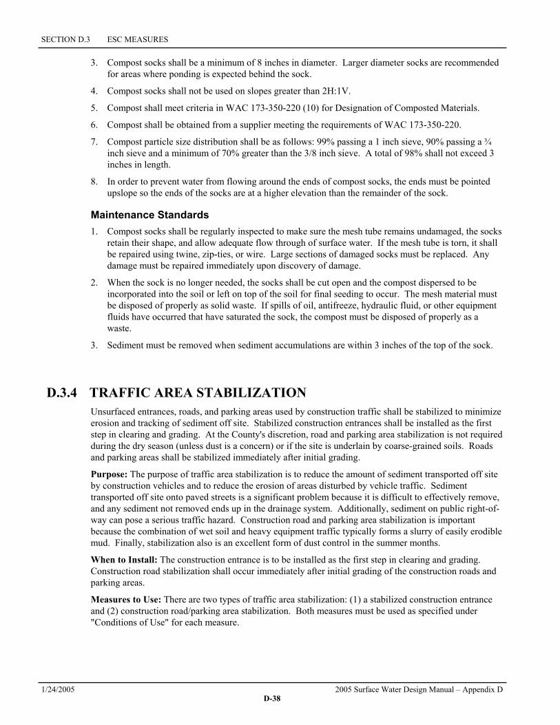
SECTION D.3 ESC MEASURES
1/24/2005 2005 Surface Water Design Manual – Appendix D D-38
3. Compost socks shall be a minimum of 8 inches in diameter. Larger diameter socks are recommended for areas where ponding is expected behind the sock.
4. Compost socks shall not be used on slopes greater than 2H:1V.
5. Compost shall meet criteria in WAC 173-350-220 (10) for Designation of Composted Materials.
6. Compost shall be obtained from a supplier meeting the requirements of WAC 173-350-220.
7. Compost particle size distribution shall be as follows: 99% passing a 1 inch sieve, 90% passing a ¾ inch sieve and a minimum of 70% greater than the 3/8 inch sieve. A total of 98% shall not exceed 3 inches in length.
8. In order to prevent water from flowing around the ends of compost socks, the ends must be pointed upslope so the ends of the socks are at a higher elevation than the remainder of the sock.
Maintenance Standards 1. Compost socks shall be regularly inspected to make sure the mesh tube remains undamaged, the socks
retain their shape, and allow adequate flow through of surface water. If the mesh tube is torn, it shall be repaired using twine, zip-ties, or wire. Large sections of damaged socks must be replaced. Any damage must be repaired immediately upon discovery of damage.
2. When the sock is no longer needed, the socks shall be cut open and the compost dispersed to be incorporated into the soil or left on top of the soil for final seeding to occur. The mesh material must be disposed of properly as solid waste. If spills of oil, antifreeze, hydraulic fluid, or other equipment fluids have occurred that have saturated the sock, the compost must be disposed of properly as a waste.
3. Sediment must be removed when sediment accumulations are within 3 inches of the top of the sock.
D.3.4 TRAFFIC AREA STABILIZATION Unsurfaced entrances, roads, and parking areas used by construction traffic shall be stabilized to minimize erosion and tracking of sediment off site. Stabilized construction entrances shall be installed as the first step in clearing and grading. At the County's discretion, road and parking area stabilization is not required during the dry season (unless dust is a concern) or if the site is underlain by coarse-grained soils. Roads and parking areas shall be stabilized immediately after initial grading.
Purpose: The purpose of traffic area stabilization is to reduce the amount of sediment transported off site by construction vehicles and to reduce the erosion of areas disturbed by vehicle traffic. Sediment transported off site onto paved streets is a significant problem because it is difficult to effectively remove, and any sediment not removed ends up in the drainage system. Additionally, sediment on public right-of-way can pose a serious traffic hazard. Construction road and parking area stabilization is important because the combination of wet soil and heavy equipment traffic typically forms a slurry of easily erodible mud. Finally, stabilization also is an excellent form of dust control in the summer months.
When to Install: The construction entrance is to be installed as the first step in clearing and grading. Construction road stabilization shall occur immediately after initial grading of the construction roads and parking areas.
Measures to Use: There are two types of traffic area stabilization: (1) a stabilized construction entrance and (2) construction road/parking area stabilization. Both measures must be used as specified under "Conditions of Use" for each measure.

D.3.4 TRAFFIC AREA STABILIZATION
2005 Surface Water Design Manual – Appendix D 1/24/2005 D-39
D.3.4.1 STABILIZED CONSTRUCTION ENTRANCE
Code: CE Symbol:
Purpose Construction entrances are stabilized to reduce the amount of sediment transported onto paved roads by motor vehicles or runoff by constructing a stabilized pad of quarry spalls at entrances to construction sites.
Conditions of Use Construction entrances shall be stabilized wherever traffic will be leaving a construction site and traveling on paved roads or other paved areas within 1,000 feet of the site.
Design and Installation Specifications 1. See Figure D.3.4.A for details.
2. A separation geotextile shall be placed under the spalls to prevent fine sediment from pumping up into the rock pad. The geotextile shall meet the following standards:
Grab Tensile Strength (ASTM D4751) 200 psi min.
Grab Tensile Elongation (ASTM D4632) 30% max.
Mullen Burst Strength (ASTM D3786-80a) 400 psi min.
AOS (ASTM D4751) 20-45 (U.S. standard sieve size)
3. Hog fuel (wood based mulch) may be substituted for or combined with quarry spalls in areas that will not be used for permanent roads. The effectiveness of hog fuel is highly variable, but it has been used successfully on many sites. It generally requires more maintenance than quarry spalls. Hog fuel is not recommended for entrance stabilization in urban areas. The inspector may at any time require the use of quarry spalls if the hog fuel is not preventing sediment from being tracked onto pavement or if the hog fuel is being carried onto pavement. Hog fuel is prohibited in permanent roadbeds because organics in the subgrade soils cause difficulties with compaction.
4. Fencing (see Section D.3.1) shall be installed as necessary to restrict traffic to the construction entrance.
5. Whenever possible, the entrance shall be constructed on a firm, compacted subgrade. This can substantially increase the effectiveness of the pad and reduce the need for maintenance.
Maintenance Standards 1. Quarry spalls (or hog fuel) shall be added if the pad is no longer in accordance with the specifications.
2. If the entrance is not preventing sediment from being tracked onto pavement, then alternative measures to keep the streets free of sediment shall be used. This may include street sweeping, an increase in the dimensions of the entrance, or the installation of a wheel wash. If washing is used, it shall be done on an area covered with crushed rock, and wash water shall drain to a sediment trap or pond.
3. Any sediment that is tracked onto pavement shall be removed immediately by sweeping. The sediment collected by sweeping shall be removed or stabilized on site. The pavement shall not be cleaned by washing down the street, except when sweeping is ineffective and there is a threat to

SECTION D.3 ESC MEASURES
1/24/2005 2005 Surface Water Design Manual – Appendix D D-40
public safety. If it is necessary to wash the streets, a small sump must be constructed. The sediment would then be washed into the sump where it can be controlled and discharged appropriately.
4. Any quarry spalls that are loosened from the pad and end up on the roadway shall be removed immediately.
5. If vehicles are entering or exiting the site at points other than the construction entrance(s), fencing (see Section D.3.1) shall be installed to control traffic.
FIGURE D.3.4.A STABILIZED CONSTRUCTION ENTRANCE

D.3.4 TRAFFIC AREA STABILIZATION
2005 Surface Water Design Manual – Appendix D 1/24/2005 D-41
D.3.4.2 CONSTRUCTION ROAD/PARKING AREA STABILIZATION
Code: CRS Symbol:
Purpose Stabilizing subdivision roads, parking areas, and other onsite vehicle transportation routes immediately after grading reduces erosion caused by construction traffic or runoff.
Conditions of Use 1. Roads or parking areas shall be stabilized wherever they are constructed, whether permanent or
temporary, for use by construction traffic.
2. Fencing (see Section D.3.1) shall be installed, if necessary, to limit the access of vehicles to only those roads and parking areas that are stabilized.
Design and Installation Specifications 1. A 6-inch depth of 2- to 4-inch crushed rock, gravel base, or crushed surfacing base course shall be
applied immediately after grading or utility installation. A 4-inch course of asphalt treated base (ATB) may also be used, or the road/parking area may be paved. It may also be possible to use cement or calcium chloride for soil stabilization. If the area will not be used for permanent roads, parking areas, or structures, a 6-inch depth of hog fuel may also be used, but this is likely to require more maintenance. Whenever possible, construction roads and parking areas shall be placed on a firm, compacted subgrade. Note: If the area will be used for permanent road or parking installation later in the project, the subgrade will be subject to inspection.
2. Temporary road gradients shall not exceed 15 percent. Roadways shall be carefully graded to drain transversely. Drainage ditches shall be provided on each side of the roadway in the case of a crowned section, or on one side in the case of a super-elevated section. Drainage ditches shall be designed in accordance with the standards given in Section D.3.6.3 (p. D-60) and directed to a sediment pond or trap.
3. Rather than relying on ditches, it may also be possible to grade the road so that runoff sheet-flows into a heavily vegetated area with a well-developed topsoil. Landscaped areas are not adequate. If this area has at least 50 feet of vegetation, then it is generally preferable to use the vegetation to treat runoff, rather than a sediment pond or trap. The 50 feet shall not include vegetated wetlands. If runoff is allowed to sheet flow through adjacent vegetated areas, it is vital to design the roadways and parking areas so that no concentrated runoff is created.
4. In order to control construction traffic, the County may require that signs be erected on site informing construction personnel that vehicles, other than those performing clearing and grading, are restricted to stabilized areas.
5. If construction roads do not adequately reduce trackout to adjacent property or roadways, a wheel wash system will be required.
Maintenance Standards Crushed rock, gravel base, hog fuel, etc. shall be added as required to maintain a stable driving surface and to stabilize any areas that have eroded.
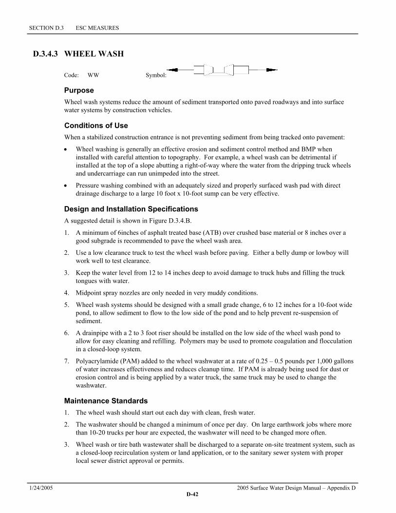
SECTION D.3 ESC MEASURES
1/24/2005 2005 Surface Water Design Manual – Appendix D D-42
D.3.4.3 WHEEL WASH
Code: WW Symbol:
Purpose Wheel wash systems reduce the amount of sediment transported onto paved roadways and into surface water systems by construction vehicles.
Conditions of Use When a stabilized construction entrance is not preventing sediment from being tracked onto pavement:
• Wheel washing is generally an effective erosion and sediment control method and BMP when installed with careful attention to topography. For example, a wheel wash can be detrimental if installed at the top of a slope abutting a right-of-way where the water from the dripping truck wheels and undercarriage can run unimpeded into the street.
• Pressure washing combined with an adequately sized and properly surfaced wash pad with direct drainage discharge to a large 10 foot x 10-foot sump can be very effective.
Design and Installation Specifications A suggested detail is shown in Figure D.3.4.B.
1. A minimum of 6inches of asphalt treated base (ATB) over crushed base material or 8 inches over a good subgrade is recommended to pave the wheel wash area.
2. Use a low clearance truck to test the wheel wash before paving. Either a belly dump or lowboy will work well to test clearance.
3. Keep the water level from 12 to 14 inches deep to avoid damage to truck hubs and filling the truck tongues with water.
4. Midpoint spray nozzles are only needed in very muddy conditions.
5. Wheel wash systems should be designed with a small grade change, 6 to 12 inches for a 10-foot wide pond, to allow sediment to flow to the low side of the pond and to help prevent re-suspension of sediment.
6. A drainpipe with a 2 to 3 foot riser should be installed on the low side of the wheel wash pond to allow for easy cleaning and refilling. Polymers may be used to promote coagulation and flocculation in a closed-loop system.
7. Polyacrylamide (PAM) added to the wheel washwater at a rate of 0.25 – 0.5 pounds per 1,000 gallons of water increases effectiveness and reduces cleanup time. If PAM is already being used for dust or erosion control and is being applied by a water truck, the same truck may be used to change the washwater.
Maintenance Standards 1. The wheel wash should start out each day with clean, fresh water.
2. The washwater should be changed a minimum of once per day. On large earthwork jobs where more than 10-20 trucks per hour are expected, the washwater will need to be changed more often.
3. Wheel wash or tire bath wastewater shall be discharged to a separate on-site treatment system, such as a closed-loop recirculation system or land application, or to the sanitary sewer system with proper local sewer district approval or permits.
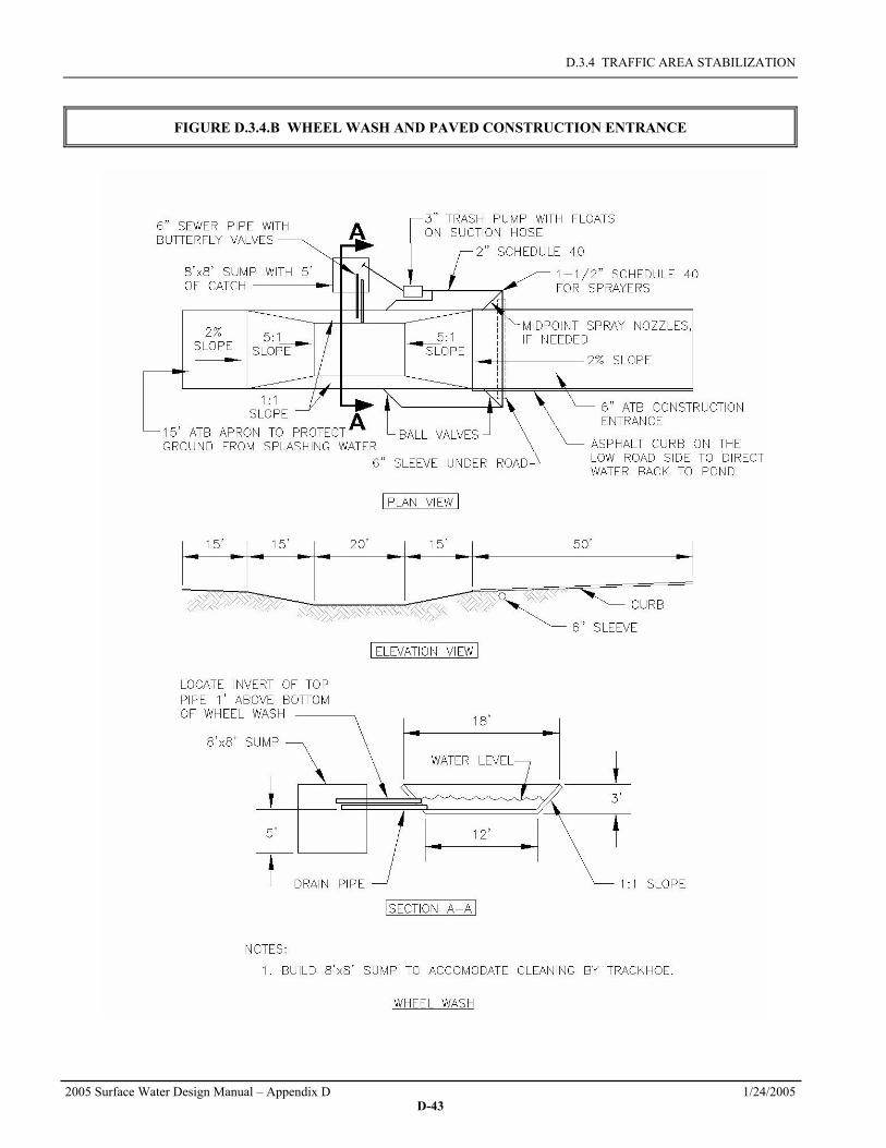
D.3.4 TRAFFIC AREA STABILIZATION
2005 Surface Water Design Manual – Appendix D 1/24/2005 D-43
FIGURE D.3.4.B WHEEL WASH AND PAVED CONSTRUCTION ENTRANCE

SECTION D.3 ESC MEASURES
1/24/2005 2005 Surface Water Design Manual – Appendix D D-44
D.3.5 SEDIMENT RETENTION Surface water collected from disturbed areas of the site shall be routed through a sediment pond or trap prior to release from the site. An exception is for areas at the perimeter of the site with drainage areas small enough to be treated solely with perimeter protection (see Section D.3.3, p. D-30). Also, if the soils and topography are such that no offsite discharge of surface water is anticipated up to and including the developed 2-year runoff event, sediment ponds and traps are not required. A 10-year/15-minute peak flow shall be used for sediment pond/trap sizing if the project size, expected timing and duration of construction, or downstream conditions warrant a higher level of protection (see below). At the County's discretion, sites may be worked during the dry season without sediment ponds and traps if there is some other form of protection of surface waters, such as a 100-foot forested buffer between the disturbed areas and adjacent surface waters. Protection of catch basins is required for inlets that are likely to be impacted by sediment generated by the project and that do not drain to an onsite sediment pond or trap. Sediment retention facilities shall be installed prior to grading of any contributing area.
Purpose: The purpose of sediment retention facilities is to remove sediment from runoff generated from disturbed areas.
When to Install: The facilities shall be constructed as the first step in the clearing and grading of the site. The surface water conveyances may then be connected to the facilities as site development proceeds.
Measures to Use: There are three sediment retention measures in this section. The first two, sediment traps and ponds, serve the same function but for different size catchments. All runoff from disturbed areas must be routed through a trap or pond except for very small areas as specified in Section D.4.3. The third measure is for catch basin protection. It is only to be used in limited circumstances and is not a primary sediment treatment facility. It is only intended as a backup in the event of failure of other onsite systems.
Use of Permanent Drainage Facilities: All projects that are constructing permanent facilities for runoff quantity control are strongly encouraged to use the rough-graded or final-graded permanent facilities for ponds and traps. This includes combined facilities and infiltration facilities. When permanent facilities are used as temporary sedimentation facilities, the surface area requirements of sediment traps (for drainages less than 3 acres) or sediment ponds (more than 3 acres) must be met. If the surface area requirements are larger than the surface area of the permanent facility, then the pond shall be enlarged to comply with the surface area requirement. The permanent pond shall also be divided into two cells as required for sediment ponds. Either a permanent control structure or the temporary control structure described in Section D.3.5.2 may be used. If a permanent control structure is used, it may be advisable to partially restrict the lower orifice with gravel to increase residence time while still allowing dewatering of the pond.
If infiltration facilities are to be used, the sides and bottom of the facility must only be rough excavated to a minimum of three feet above final grade. Excavation should be done with a backhoe working at "arms length" to minimize disturbance and compaction of the infiltration surface. Additionally, any required pretreatment facilities shall be fully constructed prior to any release of sediment-laden water to the facility. Pretreatment and shallow excavation are intended to prevent the clogging of soil with fines. Final grading of the infiltration facility shall occur only when all contributing drainage areas are fully stabilized (see Section D.5.5, p. D-74).
Selection of the Design Storm: In most circumstances, the 15-minute peak flow from the developed 2-year runoff event is sufficient for calculating surface area for ponds and traps and for determining exemptions from the sediment retention and surface water collection requirements (Sections D.3.5 and D.3.6, respectively). In some circumstances, however, the 10-year/15-minute peak flow should be used. Examples of such circumstances include the following:
• Sites that are within ¼ mile of salmonid streams, wetlands, and designated sensitive lakes such as Lake Sammamish
• Sites where significant clearing and grading is likely to occur during the wet season

D.3.5 SEDIMENT RETENTION
2005 Surface Water Design Manual – Appendix D 1/24/2005 D-45
• Sites with downstream erosion or sedimentation problems.
Natural Vegetation: Whenever possible, sediment-laden water shall be discharged into onsite, relatively level, vegetated areas. This is the only way to effectively remove fine particles from runoff. This can be particularly useful after initial treatment in a sediment retention facility. The areas of release must be evaluated on a site-by-site basis in order to determine appropriate locations for and methods of releasing runoff. Vegetated wetlands shall not be used for this purpose. Frequently, it may be possible to pump water from the collection point at the downhill end of the site to an upslope vegetated area. Pumping shall only augment the treatment system, not replace it because of the possibility of pump failure or runoff volume in excess of pump capacity.
D.3.5.1 SEDIMENT TRAP
Code: ST Symbol:
Purpose Sediment traps remove sediment from runoff originating from disturbed areas of the site. Sediment traps are typically designed to only remove sediment as small as medium silt (0.02 mm). As a consequence, they usually only result in a small reduction in turbidity.
Conditions of Use A sediment trap shall be used where the contributing drainage area is 3 acres or less.
Design and Installation Specifications 1. See Figure D.3.5.A for details.
2. If permanent runoff control facilities are part of the project, they should be used for sediment retention (see "Use of Permanent Drainage Facilities" on page D-44).
3. To determine the trap geometry, first calculate the design surface area (SA) of the trap, measured at the invert of the weir. Use the following equation:
SA = FS(Q2/Vs)
where Q2 = Design inflow (cfs) based on the 15-minute peak discharge from the developed 2-year runoff event from the contributing drainage area as computed in the hydrologic analysis. The 10-year/15-minute peak flow shall be used if the project size, expected timing and duration of construction, or downstream conditions warrant a higher level of protection. If no hydrologic analysis is required, the Rational Method may be used (Section 3.2.1 of the Surface Water Design Manual).
Vs = The settling velocity (ft/sec) of the soil particle of interest. The 0.02 mm (medium silt) particle with an assumed density of 2.65 g/cm3 has been selected as the particle of interest and has a settling velocity (Vs) of 0.00096 ft/sec.
FS = A safety factor of 2 to account for non-ideal settling.
Therefore, the equation for computing surface area becomes:
SA = 2 x Q2/0.00096 or 2080 square feet per cfs of inflow
Note: Even if permanent facilities are used, they must still have a surface area that is at least as large as that derived from the above formula. If they do not, the pond must be enlarged.

SECTION D.3 ESC MEASURES
1/24/2005 2005 Surface Water Design Manual – Appendix D D-46
4. To aid in determining sediment depth, all traps shall have a staff gage with a prominent mark one foot above the bottom of the trap.
Maintenance Standards 1. Sediment shall be removed from the trap when it reaches 1 foot in depth.
2. Any damage to the trap embankments or slopes shall be repaired.
FIGURE D.3.5.A SEDIMENT TRAP
CROSS-SECTION
TRAP OUTLET

D.3.5 SEDIMENT RETENTION
2005 Surface Water Design Manual – Appendix D 1/24/2005 D-47
D.3.5.2 SEDIMENT POND
Code: SP Symbol:
Purpose Sediment ponds remove sediment from runoff originating from disturbed areas of the site. Sediment ponds are typically designed to only remove sediment as small as medium silt (0.02 mm). As a consequence, they usually reduce turbidity only slightly.
Conditions of Use A sediment pond shall be used where the contributing drainage area is 3 acres or more.
Design and Installation Specifications 1. See Figure D.3.5.B, Figure D.3.5.C, and Figure D.3.5.D for details.
2. If permanent runoff control facilities are part of the project, they should be used for sediment retention (see "Use of Permanent Drainage Facilities" on page D-44).
Determining Pond Geometry 1. Obtain the discharge from the hydrologic calculations of the 15-minute peak flow for the 2-year
runoff event (Q2). The 10-year/15-minute peak flow shall be used if the project size, expected timing and duration of construction, or downstream conditions warrant a higher level of protection. If no hydrologic analysis is required, the Rational Method may be used (Section 3.2.1 of the Surface Water Design Manual).
2. Determine the required surface area at the top of the riser pipe with the equation:
SA = 2 x Q2/0.00096 or 2080 square feet per cfs of inflow
See Section D.3.5.1 (p. D-45) for more information on the derivation of the surface area calculation.
3. The basic geometry of the pond can now be determined using the following design criteria:
• Required surface area SA (from Step 2 above) at top of riser
• Minimum 3.5-foot depth from top of riser to bottom of pond
• Maximum 3:1 interior side slopes and maximum 2:1 exterior slopes. The interior slopes may be increased to a maximum of 2:1 if fencing is provided at or above the maximum water surface
• One foot of freeboard between the top of the riser and the crest of the emergency spillway
• Flat bottom
• Minimum one foot deep spillway
• Length-to-width ratio between 3:1 and 6:1.
Sizing of Discharge Mechanisms Principal Spillway: Determine the required diameter for the principal spillway (riser pipe). The diameter shall be the minimum necessary to pass the 15-minute peak flow from the developed 10-year runoff event (Q10). Use Figure 5.3.4.H (SWDM Chapter 5) to determine this diameter (h = one foot). Note: A permanent control structure may be used instead of a temporary riser.

SECTION D.3 ESC MEASURES
1/24/2005 2005 Surface Water Design Manual – Appendix D D-48
Emergency Overflow Spillway: Determine the required size and design of the emergency overflow spillway for the developed 100-year/15-minute peak flow using the procedure in Section 5.3.1 ("Emergency Overflow Spillway" subsection) of the Surface Water Design Manual.
Dewatering Orifice: Determine the size of the dewatering orifice(s) (minimum 1-inch diameter) using a modified version of the discharge equation for a vertical orifice and a basic equation for the area of a circular orifice.
1. Determine the required area of the orifice with the following equation:
hATg
hAA s
so )10(81.4
3600x6.0)2( 6
5.0
5.0−==
where Ao = orifice area (square feet) As = pond surface area (square feet) h = head of water above orifice (height of riser in feet) T = dewatering time (24 hours) g = acceleration of gravity (32.2 feet/second2)
2. Convert the required surface area to the required diameter D (inches) of the orifice:
oo A
AD x54.13x24 ==
π
3. The vertical, perforated tubing connected to the dewatering orifice must be at least 2 inches larger in diameter than the orifice to improve flow characteristics. The size and number of perforations in the tubing should be large enough so that the tubing does not restrict flow. The flow rate should be controlled by the orifice.
Additional Design Specifications • The pond shall be divided into two roughly equal volume cells by a permeable divider that will
reduce turbulence while allowing movement of water between cells. The divider shall be at least one-half the height of the riser and a minimum of one foot below the top of the riser. Wire-backed, 2- to 3-foot high, extra strength filter fabric (see Section D.3.3.1) supported by treated 4"x4"s may be used as a divider. Alternatively, staked straw bales wrapped with filter fabric (geotextile) may be used.
If the pond is more than 6 feet deep, a different mechanism must be proposed. A riprap embankment is one acceptable method of separation for deeper ponds. Other designs that satisfy the intent of this provision are allowed as long as the divider is permeable, structurally sound, and designed to prevent erosion under or around the barrier.
• To aid in determining sediment depth, one-foot intervals shall be prominently marked on the riser.
• If an embankment of more than 6 feet is proposed, the pond must comply with the criteria under "Embankments" in Section 5.3.1 of the Surface Water Design Manual.
Maintenance Standards 1. Sediment shall be removed from the pond when it reaches 1 foot in depth.
2. Any damage to the pond embankments or slopes shall be repaired.

D.3.5 SEDIMENT RETENTION
2005 Surface Water Design Manual – Appendix D 1/24/2005 D-49
FIGURE D.3.5.B SEDIMENT POND PLAN VIEW
FIGURE D.3.5.C SEDIMENT POND CROSS SECTION

SECTION D.3 ESC MEASURES
1/24/2005 2005 Surface Water Design Manual – Appendix D D-50
FIGURE D.3.5.D SEDIMENT POND RISER DETAIL

D.3.5 SEDIMENT RETENTION
2005 Surface Water Design Manual – Appendix D 1/24/2005 D-51
D.3.5.3 STORM DRAIN INLET PROTECTION
Code: FFP or CBI or CBP Symbol: or or
Purpose Storm drain inlets are protected to prevent coarse sediment from entering storm drainage systems. Temporary devices around storm drains assist in improving the quality of water discharged to inlets or catch basins by ponding sediment-laden water. These devices are effective only for relatively small drainage areas.
Conditions of Use 1. Protection shall be provided for all storm drain inlets downslope and within 500 feet of a disturbed or
construction area, unless the runoff that enters the catch basin will be conveyed to a sediment pond or trap.
2. Inlet protection may be used anywhere at the applicant's discretion to protect the drainage system. This will, however, require more maintenance, and it is highly likely that the drainage system will still require some cleaning.
3. The contributing drainage area must not be larger than one acre.
Design and Installation Specifications 1. There are many options for protecting storm drain inlets. Two commonly used options are filter
fabric protection and catch basin inserts. Filter fabric protection (see Figure D.3.5.E) is filter fabric (geotextile) placed over the grate. This method is generally very ineffective and requires intense maintenance efforts. Catch basin inserts (see Figure D.3.5.F) are manufactured devices that nest inside a catch basin. This method also requires a high frequency of maintenance to be effective. Both options provide adequate protection, but filter fabric is likely to result in ponding of water above the catch basin, while the insert will not. Thus, filter fabric is only allowed where ponding will not be a traffic concern and where slope erosion will not result if the curb is overtopped by ponded water.
Trapping sediment in the catch basins is unlikely to improve the water quality of runoff if it is treated in a pond or trap because the coarse particles that are trapped at the catch basin settle out very quickly in the pond or trap. Catch basin protection normally only improves water quality where there is no treatment facility downstream. In these circumstances, catch basin protection is an important last line of defense. It is not, however, a substitute for preventing erosion.
The placement of filter fabric under grates is generally prohibited and the use of filter fabric over grates is strictly limited and discouraged.
2. It is sometimes possible to construct a small sump around the catch basin before final surfacing of the road. This is allowed because it can be a very effective method of sediment control.
3. Block and gravel filters, gravel and wire mesh filter barriers, and bag barriers filled with various filtering media placed around catch basins can be effective when the drainage area is 1 acre or less and flows do not exceed 0.5 cfs. It is necessary to allow for overtopping to prevent flooding. Many manufacturers have various inlet protection filters that are very effective in keeping sediment-laden water from entering the storm drainage system. The following are examples of a few common methods.
a) Block and gravel filters (Figure D.3.5.G) are a barrier formed around an inlet with standard concrete block and gravel, installed as follows:
• Height is 1 to 2 feet above the inlet.

SECTION D.3 ESC MEASURES
1/24/2005 2005 Surface Water Design Manual – Appendix D D-52
• Recess the first row of blocks 2 inches into the ground for stability.
• Support subsequent rows by placing a 2x4 through the concrete block opening.
• Do not use mortar.
• Lay some blocks in the bottom row on their side for dewatering the pooled water.
• Place cloth or mesh with ½ inch openings over all block openings.
• Place gravel below the top of blocks on slopes of 2:1 or flatter.
• An alternate design is a gravel donut.
b) Gravel and wire mesh filters consist of a gravel barrier placed over the top of an inlet. This structure generally does not provide overflow. Install as follows:
• Cloth or comparable wire mesh with ½ inch openings is placed over inlet.
• Coarse aggregate covers the cloth or mesh.
• Height/depth of gravel should be 1 foot or more, 18 inches wider than inlet on all sides.
c) Curb inlet protection with a wooden weir is a barrier formed around an inlet with a wooden frame and gravel, installed as follows:
• Construct a frame and attach wire mesh (½ inch openings) and filter fabric to the frame.
• Pile coarse washed aggregate against the wire/fabric.
• Place weight on frame anchors.
d) Curb and gutter sediment barriers (Figure D.3.5.H) consist of sandbags or rock berms (riprap and aggregate) 3 feet high and 3 feet wide in a horseshoe shape, installed as follows:
• Bags of either burlap or woven geotextile fabric, filled with a variety of media such as gravel, wood chips, compost or sand stacked tightly allows water to pond and allows sediment to separate from runoff.
• Leave a "one bag gap" in the top row of the barrier to provide a spillway for overflow.
• Construct a horseshoe shaped berm, faced with coarse aggregate if using riprap, 3 x 3 and at least 2 feet from the inlet.
• Construct a horseshoe shaped sedimentation trap on the outside of the berm to sediment trap standards for protecting a culvert inlet.
4. Excavated drop inlet sediment traps are appropriate where relatively heavy flows are expected and overflow capability is needed. If emergency overflow is provided, additional end-of-pipe treatment may be required. Excavated drop inlets consist of an excavated impoundment area around a storm drain. Sediment settles out of the stormwater prior to enter the drain. Install according to the following specifications:
a) The impoundment area should have a depth of 1 - 2 feet measured from the crest of the inlet structure.
b) Side slopes of the excavated area must be no steeper than 2:1.
c) Minimum volume of the excavated area should be 35 cubic yards.
d) Install provisions for draining the area to prevent standing water problems.
e) Keep the area clear of debris.
f) Weep holes may be drilled into the side of the inlet.
g) Protect weep holes with wire mesh and washed aggregate.

D.3.5 SEDIMENT RETENTION
2005 Surface Water Design Manual – Appendix D 1/24/2005 D-53
h) Weep holes must be sealed when removing and stabilizing excavated area.
i) A temporary dike may be necessary on the down slope side of the structure to prevent bypass flow.
Maintenance Standards 1. Any accumulated sediment on or around inlet protection shall be removed immediately. Sediment
shall not be removed with water, and all sediment must be disposed of as fill on site or hauled off site.
2. Any sediment in the catch basin insert shall be removed when the sediment has filled one-third of the available storage. The filter media for the insert shall be cleaned or replaced at least monthly.
3. Regular maintenance is critical for all forms of catch basin/inlet protection. Unlike many forms of protection that fail gradually, catch basin protection will fail suddenly and completely if not maintained properly.
FIGURE D.3.5.E FILTER FABRIC PROTECTION
FIGURE D.3.5.F CATCH BASIN INSERT

SECTION D.3 ESC MEASURES
1/24/2005 2005 Surface Water Design Manual – Appendix D D-54
FIGURE D.3.5.G BLOCK AND GRAVEL CURB INLET PROTECTION
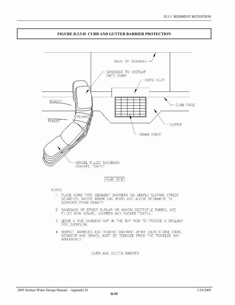
D.3.5 SEDIMENT RETENTION
2005 Surface Water Design Manual – Appendix D 1/24/2005 D-55
FIGURE D.3.5.H CURB AND GUTTER BARRIER PROTECTION

SECTION D.3 ESC MEASURES
1/24/2005 2005 Surface Water Design Manual – Appendix D D-56
D.3.6 SURFACE WATER COLLECTION All surface water from disturbed areas shall be intercepted, conveyed to a sediment pond or trap, and discharged downslope of any disturbed areas. An exception is for areas at the perimeter of the site with drainage areas small enough to be treated solely with perimeter protection (see Section D.3.3). Also, if the soils and topography are such that no offsite discharge of surface water is anticipated up to and including the developed 2-year runoff event, surface water controls are not required. A 10-year/15-minute peak flow shall be used for sizing surface water controls if the project size, expected timing and duration of construction, or downstream conditions warrant a higher level of protection (see the introduction to Section D.3.5). At the County's discretion, sites may be worked during the dry season without surface water controls, if there is some other form of protection of surface waters, such as a 100-foot forested buffer between the disturbed areas and adjacent surface waters. Significant sources of upslope surface water that drain onto disturbed areas shall be intercepted and conveyed to a stabilized discharge point downslope of the disturbed areas. Surface water controls shall be installed concurrently with rough grading.
Purpose: The purpose of surface water control is to collect and convey surface water so that erosion is minimized, and runoff from disturbed areas is treated by a sediment pond or trap. Surface water control essentially consists of three elements:
1. Interception of runoff on and above slopes
2. Conveyance of the runoff to a sediment pond or trap (if the runoff was collected from a disturbed area)
3. Release of the runoff downslope of any disturbed areas.
When to Install: Surface water controls shall be constructed during the initial grading of an area and must be in place before there is any opportunity for storm runoff to cause erosion.
Measures to Install: Interceptor dikes/swales intercept runoff, ditches and pipe slope drains convey the runoff, and riprap or level spreaders help release the runoff in a non-erosive manner. Each measure is to be used under different circumstances so there is very little overlap. However, the two options for releasing water in a non-erosive manner, outlet protection and level spreaders, can be somewhat interchangeable. See Figure D.3.6.A for a schematic drawing demonstrating the use of these measures.

D.3.6 SURFACE WATER COLLECTION
2005 Surface Water Design Manual – Appendix D 1/24/2005 D-57
FIGURE D.3.6.A SKETCH PLAN OF SURFACE WATER CONTROLS
D.3.6.1 INTERCEPTOR DIKE AND SWALE
Code: ID or IS Symbol: or
Purpose Interceptor dikes and swales intercept storm runoff from drainage areas on or above disturbed slopes and convey it to a sediment pond or trap. They may also be used to intercept runoff from undisturbed areas and convey the runoff to a point below any exposed soils. Interception of surface water reduces the possibility of slope erosion. Interceptor dikes and swales differ from ditches (see Section D.3.6.3) in that they are intended to convey smaller flows along low-gradient drainage ways to larger conveyance systems such as ditches or pipe slope drains.
Conditions of Use Interceptor dikes and swales are required in the following situations:
1. At the top of all slopes in excess of 3H:1V and with more than 20 feet of vertical relief.
2. At intervals on any slope that exceeds the dimensions specified in this section for the horizontal spacing of dikes and swales.
Design and Installation Specifications 1. See Figure D.3.6.B for details of an interceptor dike and Figure D.3.6.C for an interceptor swale.

SECTION D.3 ESC MEASURES
1/24/2005 2005 Surface Water Design Manual – Appendix D D-58
2. Interceptor dikes and swales shall be spaced horizontally as follows:
Average Slope Slope Percent Flowpath Length
20H:1V or less 3-5% 300 feet
(10 to 20)H:1V 5-10% 200 feet
(4 to 10)H:1V 10-25% 100 feet
(2 to 4)H:1V 25-50% 50 feet
3. For slopes steeper than 2H:1V with more than 10 feet of vertical relief, benches may be constructed or closer spaced interceptor dikes or swales may be used. Whichever measure is chosen, the spacing and capacity of the measures must be designed by the engineer and the design must include provisions for effectively intercepting the high velocity runoff associated with steep slopes.
4. If the dike or swale intercepts runoff from disturbed areas, it shall discharge to a stable conveyance system that routes the runoff to a sediment pond or trap (see Section D.3.5). If the dike or swale intercepts runoff that originates from undisturbed areas, it shall discharge to a stable conveyance system that routes the runoff downslope of any disturbed areas and releases the water at a stabilized outlet.
5. Construction traffic over temporary dikes and swales shall be minimized.
Maintenance Standards 1. Damage resulting from runoff or construction activity shall be repaired immediately.
2. If the facilities do not regularly retain storm runoff, the capacity and/or frequency of the dikes/swales shall be increased.
FIGURE D.3.6.B INTERCEPTOR DIKE
FIGURE D.3.6.C INTERCEPTOR SWALE

D.3.6 SURFACE WATER COLLECTION
2005 Surface Water Design Manual – Appendix D 1/24/2005 D-59
D.3.6.2 PIPE SLOPE DRAINS
Code: PD Symbol:
Purpose Pipe slope drains are designed to carry concentrated runoff down steep slopes without causing erosion, or saturation of slide-prone soils. Pipe slope drains may be used to divert water away from or over bare soil to prevent gullies, channel erosion, and saturation of slide prone soils
Conditions of Use Pipe slope drains should be used when a temporary or permanent stormwater conveyance is needed to move water down a steep slope to avoid erosion. Pipe slope drains may be:
1. Connected to new catch basins and used temporarily until all permanent piping is installed.
2. Used on any slope with a gradient of 2H:1V or greater and with at least 10 feet of vertical relief.
3. Used to drain water collected from aquifers exposed on cut slopes and convey it to the base of the slope.
4. Used to collect clean runoff from plastic sheet cover and direct away from any exposed soils.
5. Installed in conjunction with silt fence to drain collected water to a controlled area.
6. Used to divert small seasonal streams away from construction. Pipe slope drains have been used successfully on culvert replacement and extension projects. Large flex pipe may be used on larger streams during culvert removal, repair, or replacement.
7. Connected to existing downspouts and roof drains used to divert water away from work areas during building renovation, demolition, and construction projects.
8. Rock-lined ditches or other permanent, non-erosive conveyances used to convey runoff down steep slopes that are not steep slope hazard areas.
Design and Installation Specifications 1. See Figure D.3.6.D for details.
2. The capacity for temporary drains shall be sufficient to handle the 15-minute peak flow from a developed 10-year runoff event. Up to 30,000 square feet may be drained by each 6-inch minimum diameter pipe without computation of the peak flow. Up to 2 acres may be drained by each 12-inch minimum diameter pipe. Otherwise, the peak flow will need to be computed using the Rational Method described in Section 3.2.1 of the Surface Water Design Manual (SWDM).
3. The maximum drainage area allowed for any sized pipe is 10 acres. For larger areas, more than one pipe shall be used or a rock-lined channel shall be installed (see SWDM Section 4.4.1, "Open Channels").
4. The soil around and under the pipe and entrance section shall be thoroughly compacted.
5. The flared inlet section shall be securely connected to the slope drain and be fused or welded, or have flange-bolted mechanical joints to ensure a watertight seal. Ensure that the entrance area is stable and large enough to direct flow into the pipe.
6. Slope drains shall be continuously fused, welded, or flange-bolted mechanical joint pipe systems with proper anchoring to the soil.
7. Where slope drains cross steep slope hazard areas or their associated buffers, the installation shall be on the ground surface, accomplished with minimum alteration. In most circumstances, this requires

SECTION D.3 ESC MEASURES
1/24/2005 2005 Surface Water Design Manual – Appendix D D-60
that slope drains be constructed of corrugated metal, CPE, or equivalent pipe and installed by hand (see SWDM Section 4.2.1). Any area disturbed during installation or maintenance must be immediately stabilized.
8. If the pipe slope drain will convey sediment-laden runoff, the runoff must be directed to a sediment retention facility (see Section D.3.5). If the runoff is not from a disturbed area or is conveyed from a sediment trap or pond, it must be conveyed to a stabilized discharge point (see Section D.3.6.5).
9. Re-establish cover immediately on areas disturbed by the installation.
Maintenance Standards 1. The inlet shall not be undercut or bypassed by water. If there are problems, the head wall shall be
appropriately reinforced.
2. No erosion shall occur at the outlet point. If erosion occurs, additional protection shall be added.
FIGURE D.3.6.D PIPE SLOPE DRAIN
D.3.6.3 SUBSURFACE DRAINS
Purpose To intercept, collect, and convey ground water to a satisfactory outlet, using a perforated pipe or conduit below the ground surface. Subsurface drains are also known as "French Drains." The perforated pipe provides a dewatering mechanism to drain excessively wet soils, provide a stable base for construction, improve stability of structures with shallow foundations, or to reduce hydrostatic pressure and to improve slope stability.
Conditions of Use Use when excessive water must be removed from the soil. The soil permeability, depth to water table, and impervious layers are all factors that may govern the use of subsurface drains.
Design and Installation Specifications 1. Two types of drains may be used as follows:

D.3.6 SURFACE WATER COLLECTION
2005 Surface Water Design Manual – Appendix D 1/24/2005 D-61
a) Relief drains are used either to lower the water table in large, relatively flat areas, improve the growth of vegetation, or to remove surface water. They are installed along a slope and drain in the direction of the slope. They may be installed in a grid pattern, a herringbone pattern, or a random pattern.
b) Interceptor drains are used to remove excess groundwater from a slope, stabilize steep slopes, and lower the water table below a slope to prevent the soil from becoming saturated. They are installed perpendicular to a slope and drain to the side of the slope. They usually consist of a single pipe or single pipes instead of a patterned layout.
2. Size of Drains – Size subsurface drains to carry the required capacity without pressurized flow. Minimum diameter for a subsurface drain is 4 inches.
3. Outlet – Ensure that the outlet of a drain empties into a channel or other watercourse above the normal water level.
Maintenance Standards 1. Subsurface drains shall be checked periodically to ensure that they are free flowing and not clogged
with sediment or roots.
2. The outlet shall be kept clear and free of debris.
3. Surface inlets shall be kept open and free of sediment and other debris.
4. Trees located too close to a subsurface drain often clog the system with roots. If a drain becomes clogged, relocate the drain or remove the trees as a last resort. Drain placement should be planned to minimize this problem.
5. Where drains are crossed by heavy equipment, the line shall be checked to ensure that it is not crushed and have adequate cover protection.
D.3.6.4 DITCHES
Code: DI Symbol:
Purpose Ditches convey intercepted runoff from disturbed areas to and from sediment ponds or traps. They also convey runoff intercepted from undisturbed areas around the site to a non-erosive discharge point.
Conditions of Use Ditches may be used anywhere that concentrated runoff is to be conveyed on or around the construction site. Temporary pipe systems may also be used to convey runoff.
Design and Installation Specifications 1. Channels and ditches shall be sized to accommodate the 15-minute peak flow from the developed 10-
year runoff event with 0.5 feet of freeboard. If no hydrologic analysis is required for the site, the Rational Method may be used [see Section 3.2.1 of the Surface Water Design Manual (SWDM)].
2. See SWDM Section 4.4.1 for open-channel design requirements.
3. The only exception to the requirements of SWDM Section 4.4.1 is the use of check dams, rather than grass lining, for channels in which the design flow velocity does not exceed 5 fps. See Figure D.3.6.E for details on check dam installation.

SECTION D.3 ESC MEASURES
1/24/2005 2005 Surface Water Design Manual – Appendix D D-62
Maintenance Standards 1. Any sediment deposition of more than 0.5 feet shall be removed so that the channel is restored to its
design capacity.
2. If the channel capacity is insufficient for the design flow, it must be determined whether the problem is local (e.g., a constriction or bend) or the channel is under-designed. If the problem is local, the channel capacity must be increased through construction of a berm(s) or by excavation. If the problem is under-design, the design engineer shall be notified and the channel redesigned to a more conservative standard to be approved by King County.
3. The channel shall be examined for signs of scouring and erosion of the bed and banks. If scouring or erosion has occurred, affected areas shall be protected by riprap or an erosion control blanket or net.
FIGURE D.3.6.E CHECK DAMS
CROSS SECTION
CHECK DAM SPACING

D.3.6 SURFACE WATER COLLECTION
2005 Surface Water Design Manual – Appendix D 1/24/2005 D-63
D.3.6.5 OUTLET PROTECTION
Code: OP Symbol:
Purpose Outlet protection prevents scour at conveyance outlets.
Conditions of Use Outlet protection is required at the outlets of all ponds, pipes, ditches, or other approved conveyances, and where runoff is conveyed to a natural or manmade drainage feature such as a stream, wetland, lake, or ditch.
Design and Installation Specifications For the standard pipe slope drains in Section D.3.6.2 and other smaller conveyance systems, the standard rock pad (6 feet by 8 feet) made of 1-foot thick quarry spall is adequate. For all other outlets, the outlet protection shall meet the requirements of the "Outfalls" section of Core Requirement #4 and Section 4.2.2 of the Surface Water Design Manual.
Maintenance Standards for Outlet Protection If there is scour at the outlet, the eroded area shall be protected with more conservative measures proposed by the design engineer and approved by King County.
D.3.6.6 LEVEL SPREADER
Code: LS Symbol:
Purpose Level spreaders convert concentrated runoff to sheet flow and release it onto areas stabilized by existing vegetation.
Conditions of Use Level spreaders may be used where runoff from undisturbed areas or sediment retention facilities is discharged. This practice applies only where the spreader can be constructed on undisturbed soil and the area below the level lip is vegetated and low gradient (see below).
Note: Level spreaders are conceptually an ideal way to release stormwater since the vegetation and soil allow for the removal of fines from runoff that cannot be removed by settling or filtration. Unfortunately, the performance record of spreaders in the field is dismal. They are frequently under-designed and, despite the best installations, are rarely perfectly level, which results in the release of stormwater at a particular point. This concentrated runoff can result in catastrophic erosion downslope. Given such design failures, the use of spreaders is not encouraged. However, where slopes are gentle and the water volume is relatively low, spreaders may still be the best method. When proposing their use, the designer shall carefully evaluate the site for possible concerns.
Design and Installation Specifications 1. See Figure D.3.6.F for detail. Other designs may be used subject to County approval.

SECTION D.3 ESC MEASURES
1/24/2005 2005 Surface Water Design Manual – Appendix D D-64
2. If runoff velocity as it enters the level spreader is more than 4 fps for the developed 10-year/15-minute peak flow, a riprap apron must be provided to dissipate energy before the runoff enters the spreader (Section D.3.6.5).
3. The total spreader length shall be at least the square root of the catchment area. The maximum length for an individual spreader is 50 feet, limiting the catchment area that a single spreader may serve to 2500 square feet. Although this is very small, four 50-foot level spreaders next to one another could serve nearly an acre (40,000 square feet). Multiple spreaders shall not be placed uphill or downhill from one another in a configuration that would allow water released from one spreader to enter a downslope spreader.
4. The area below the spreader for a horizontal distance of 100 feet shall not exceed 20 percent and shall be completely vegetated with no areas of instability or erosion. The topography for a horizontal distance of 50 feet below the spreader shall be uniform so that runoff is not funneled into a swale or channel immediately after its release.
5. The level spreader shall be seeded and mulched in accordance with Section D.3.2 (p. D-10).
Maintenance Standards 1. Any damage to the spreader shall be immediately repaired.
2. The downslope area shall be checked for signs of erosion and to verify that the spreader is not functioning as a point discharge. Any eroded areas shall be immediately stabilized, and the cause determined and eliminated if possible. If the erosion is recurrent and the design, even when properly installed and maintained, is not adequate to prevent erosion, a new method of releasing runoff shall be installed in accordance with the standards of this appendix. Any new design must be approved by King County.
FIGURE D.3.6.F LEVEL SPREADER
CROSS SECTION
DETAIL OF SPREADER

D.3.7 DEWATERING CONTROL
2005 Surface Water Design Manual – Appendix D 1/24/2005 D-65
D.3.7 DEWATERING CONTROL Any runoff generated by dewatering shall be treated through construction of a sediment trap (Section D.3.5.1) when there is sufficient space or by releasing the water to a well vegetated, gently sloping area. Since pumps are used for dewatering, it may be possible to pump the sediment-laden water well away from the surface water so that vegetation can be more effectively utilized for treatment. Discharge of sediment-laden water from dewatering activities to surface and storm waters is prohibited. If dewatering occurs from areas where the water has come in contact with new concrete, such as tanks, vaults, or foundations, the pH of the water must be monitored and must be neutralized prior to discharge.
Purpose: To prevent the untreated discharge of sediment-laden water from dewatering of utilities, excavated areas, foundations, etc.
When to Install: Dewatering control measures shall be used whenever there is a potential for runoff from dewatering of utilities, excavations, foundations, etc.
Measures to install:
1. A straw bale filter shall be placed around the discharge from a dewatering pump.
2. If there is not space for a sediment trap or 25 feet of suitable vegetation, other filtration methods shall be required consistent with KCC 9.12. Dewatering structures shall be sized to allow water to flow through the filtering media without overflowing the structure.
3. Portable sediment tanks, such as Baker tanks, may be necessary to capture and treat sediment-laden runoff generated by dewatering.
4. Runoff from dewatering may have to be discharged to the sanitary sewer especially if the site is a known contaminated site and has a history of soil or groundwater contamination, specifically petroleum hydrocarbons, pH abnormalities, or metals contamination. An approval for discharge to the sanitary sewer must be secured from the local sewer agency.
D.3.8 DUST CONTROL Preventative measures to minimize the wind transport of soil shall be taken when a traffic hazard may be created or when sediment transported by wind is likely to be deposited in water resources or adjacent properties.
Purpose: To prevent wind transport of dust from exposed soil surfaces onto roadways, drainage ways, and surface waters.
When to Install: Dust control shall be implemented when exposed soils are dry to the point that wind transport is possible and roadways, drainage ways, or surface waters are likely to be impacted. Dust control measures may consist of chemical, structural, or mechanical methods.
Measures to Install: Water is the most common dust control (or palliative) used in the area. When using water for dust control, the exposed soils shall be sprayed until wet, but runoff shall not be generated by spraying. Calcium chloride, Magnesium chloride, Lignin derivatives, Tree Resin Emulsions, and Synthetic Polymer Emulsions may also be used for dust control. Exposed areas shall be re-sprayed as needed. Oil shall not be used for dust control. The following table lists many common dust control measures. Some of the measures are not recommended for use in King County and must have prior approval prior to use from the DDES inspector assigned to specific projects.
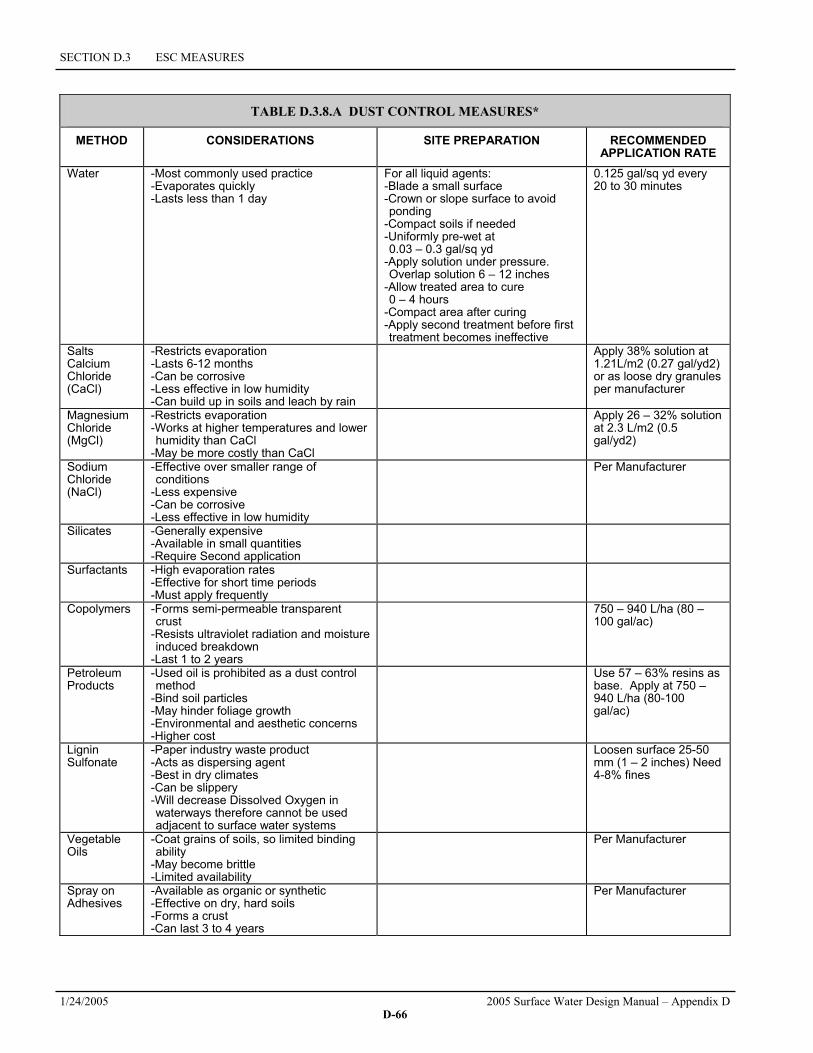
SECTION D.3 ESC MEASURES
1/24/2005 2005 Surface Water Design Manual – Appendix D D-66
TABLE D.3.8.A DUST CONTROL MEASURES*
METHOD CONSIDERATIONS SITE PREPARATION RECOMMENDED APPLICATION RATE
Water -Most commonly used practice -Evaporates quickly -Lasts less than 1 day
For all liquid agents: -Blade a small surface -Crown or slope surface to avoid ponding
-Compact soils if needed -Uniformly pre-wet at 0.03 – 0.3 gal/sq yd
-Apply solution under pressure. Overlap solution 6 – 12 inches
-Allow treated area to cure 0 – 4 hours
-Compact area after curing -Apply second treatment before first treatment becomes ineffective
0.125 gal/sq yd every 20 to 30 minutes
Salts Calcium Chloride (CaCl)
-Restricts evaporation -Lasts 6-12 months -Can be corrosive -Less effective in low humidity -Can build up in soils and leach by rain
Apply 38% solution at 1.21L/m2 (0.27 gal/yd2) or as loose dry granules per manufacturer
Magnesium Chloride (MgCl)
-Restricts evaporation -Works at higher temperatures and lower humidity than CaCl
-May be more costly than CaCl
Apply 26 – 32% solution at 2.3 L/m2 (0.5 gal/yd2)
Sodium Chloride (NaCl)
-Effective over smaller range of conditions
-Less expensive -Can be corrosive -Less effective in low humidity
Per Manufacturer
Silicates -Generally expensive -Available in small quantities -Require Second application
Surfactants -High evaporation rates -Effective for short time periods -Must apply frequently
Copolymers -Forms semi-permeable transparent crust
-Resists ultraviolet radiation and moisture induced breakdown
-Last 1 to 2 years
750 – 940 L/ha (80 – 100 gal/ac)
Petroleum Products
-Used oil is prohibited as a dust control method
-Bind soil particles -May hinder foliage growth -Environmental and aesthetic concerns -Higher cost
Use 57 – 63% resins as base. Apply at 750 – 940 L/ha (80-100 gal/ac)
Lignin Sulfonate
-Paper industry waste product -Acts as dispersing agent -Best in dry climates -Can be slippery -Will decrease Dissolved Oxygen in waterways therefore cannot be used adjacent to surface water systems
Loosen surface 25-50 mm (1 – 2 inches) Need 4-8% fines
Vegetable Oils
-Coat grains of soils, so limited binding ability
-May become brittle -Limited availability
Per Manufacturer
Spray on Adhesives
-Available as organic or synthetic -Effective on dry, hard soils -Forms a crust -Can last 3 to 4 years
Per Manufacturer

D.3.9 FLOW CONTROL
2005 Surface Water Design Manual – Appendix D 1/24/2005 D-67
D.3.9 FLOW CONTROL Surface water from disturbed areas must be routed through the project's onsite flow control facility or other provisions must made to prevent increases in the existing site conditions 2-year and 10-year runoff peaks discharging from the project site during construction.
Purpose: The purpose of surface water flow control is to mitigate increases in runoff peaks that occur during construction as a result of clearing vegetation, compacting the soil, and adding impervious surface. Such increases can cause or aggravate downstream flooding and erosion.
When to Install: Surface water flow control shall be installed or otherwise provided prior to any clearing and/or grading of the site, except that required to construct the surface water flow control facilities.
Measures to Use: The project's onsite flow control facility or other equivalent storage facility that meets the peak-matching performance criteria stated above.


KING COUNTY, WASHINGTON, SURFACE WATER DESIGN MANUAL
2005 Surface Water Design Manual – Appendix D 1/24/2005 D-69
D.4 ESC PERFORMANCE AND COMPLIANCE PROVISIONS The changing conditions typical of construction sites call for frequent field adjustments of existing ESC measures or additional ESC measures in order to meet required performance. In some cases, strict adherence to specified measures may not be necessary or practicable based on site conditions or project type. The provisions contained in this section specify the minimum performance required and the circumstances under which the County may add to or vary from the ESC standards in this appendix to meet this performance.
D.4.1 ESC PERFORMANCE ESC measures shall be applied and maintained so as to prevent, to the maximum extent practicable, the transport of sediment from the project site to downstream drainage systems or surface waters or into onsite wetlands, streams, or lakes. This performance is intended to be achieved through proper selection, installation, and operation of the above ESC measures as detailed in the ESC Standards (detached Appendix D) and approved by the County. However, the ESC supervisor or the County may determine at any time during construction that such approved measures are not sufficient and additional action is required based on one of the following criteria:
1. IF a turbidity test of storm and surface water discharges leaving the project site or entering onsite wetlands, streams, or lakes indicates a turbidity level greater than 25 NTU (nephelometric units) above the background levels of offsite storm and surface water flows entering the project site, OR if storm and surface water discharges from onsite activity areas exceed 25 NTU, THEN corrective actions and/or additional measures beyond those specified in Section D.3 shall be implemented as deemed necessary by the County inspector or ESC supervisor. Note: The ESC supervisor shall have a turbidity meter onsite and shall use it whenever runoff occurs from onsite activities and during storm events.
2. IF a turbidity test indicates a turbidity level greater than 100 NTU, THEN County inspection staff shall be notified immediately and corrective actions and/or additional measures beyond those specified in Section D.3 shall be implemented as deemed necessary by the County.
3. IF the County determines that the condition of the construction site poses a hazard to adjacent property or may adversely impact drainage facilities or water resources, THEN additional measures beyond those specified in Section D.3 may be required by the County.
D.4.2 FLEXIBLE COMPLIANCE Some projects may meet the intent of Core Requirement #5 while varying from specific ESC requirements in this appendix. If a project is designed and constructed such that it meets the intent of core requirement, the County may determine that strict adherence to a specific ESC requirement is unnecessary; an approved adjustment (see Section 1.4) from the SWDM is not required in these circumstances. Certain types of projects are particularly likely to warrant this greater level of flexibility; for instance, projects on relatively flat, well drained soils, projects that are constructed in closed depressions, or projects that only disturb a small percentage of a forested site may meet the intent of this requirement with very few ESC measures.
D.4.3 ROADS AND UTILITIES COMPLIANCE Road and utility projects often pose difficult erosion control challenges because they frequently cross surface waters and because narrow right-of-way constrains areas available to store and treat sediment-laden water. In most cases, the standards of this appendix may be applied to such linear projects without

SECTION D.4 ESC PERFORMANCE AND COMPLIANCE PROVISIONS
1/24/2005 2005 Surface Water Design Manual – Appendix D D-70
modification. For instance, the ability to use perimeter control rather than a sediment retention facility for small drainage areas (see Section D.3.3) will apply to many of these projects.
However, there may be some projects that cannot reasonably meet the standards of Core Requirement #5 and this appendix. In these cases, other measures may be proposed that will provide reasonable protection. An adjustment is not required for such projects, unless the County determines that measures proposed by the applicant fail to meet the intent of Core Requirement #5 and this appendix, and that significant adverse impacts to surface water may result. Examples of other measures that may be taken in lieu of the standards of this appendix are:
1. Phasing the project so that the site is worked progressively from end to end, rather than clearing and grubbing the entire length of the project. This results in smaller exposed areas for shorter durations, thus reducing the erosion risk. It is recommended that there be no more than 500 feet of open trench during any phase of construction.
2. Placement of excavated materials from utility trenches on the upslope side of the excavation, to minimize transport of sediment outside of the project area.
3. Mulching and vegetating cut and fill slopes as soon as they are graded. Frequently, this is done at the end of construction when paving or utility installation is complete. Vegetating these areas at the start of the project stabilizes those areas most susceptible to erosion.
4. Protecting all catch basin inlets with catch basin inserts or other inlet protection when these do not drain to ponds or traps. This will not provide the same level of protection as a sediment pond or trap, but can remove most of the sand-sized material entrained in the runoff.
5. Phasing the project so that all clearing and grading in critical area buffers occurs in the dry season. This substantially reduces the chance of erosion and allows for rapid revegetation in the late summer and early fall.
6. Using approved flocculent or other chemical treatment approved by King County to reduce the turbidity of water released from sediment ponds.
7. Hiring a private consultant with expertise in ESC to review and monitor the site.
If alternatives are used, it may be appropriate to develop a monitoring program that would monitor compliance with the performance standard of Core Requirement #5 and/or impacts to nearby water resources. Of particular concern are impacts to salmonid spawning gravels. McNeil sampling is a possible method of sampling to determine impacts to spawning gravels (see Section D.5.3).
D.4.4 ALTERNATIVE AND EXPERIMENTAL MEASURES In general, the Surface Water Design Manual only contains those BMPs that are standards of the local industry. There are a variety of other BMPs available that may also be used, even though they are not included in this appendix. Such alternatives may be approved without an adjustment if the alternative will produce a compensating or comparable result with the measures in this appendix. Variations on or modifications of the BMPs in this appendix may also be granted based on the same criteria. Technical support will be provided by WLRD when requested by DDES.
An adjustment is only required for those products or techniques that are so new and untested as to be experimental. If the County determines that a proposed alternative is experimental, then an experimental adjustment must be obtained (see Section 1.4.4 of the SWDM). The intent of this requirement is not to discourage new techniques, but to insure that new techniques are monitored and documented for adequacy and possible inclusion in subsequent versions of the SWDM. An example of a product that would have required an experimental adjustment prior to this version of the manual is the catch basin insert (see Section D.3.5.3) because it was not equivalent to any existing measure.

KING COUNTY, WASHINGTON, SURFACE WATER DESIGN MANUAL
2005 Surface Water Design Manual – Appendix D 1/24/2005 D-71
D.5 ESC IMPLEMENTATION REQUIREMENTS This section describes the ESC implementation requirements that are required at each construction site. The measures and practices correspond to the implementation requirements in Core Requirement #5. Three of the sections [the ESC report (Section D.5.1, below), ESC maintenance requirements (Section D.5.4, p. D-73), and final site stabilization (Section D.5.5, p. D-74)] are required of every project. The rest of the sections are special requirements that may apply to the project depending on site conditions and project type. The introductory paragraphs at the beginning of most sections present the purpose of the measures and when they should be applied to the site. Compliance with the implementation requirements (as appropriate for the site) ensures compliance with the ESC measures. Note, however, that additional measures shall be required by the County if the existing standards are insufficient to protect adjacent properties, drainage facilities, or water resources.
D.5.1 ESC PLAN An ESC plan, showing the location and details of ESC measures, is required for all proposed projects and shall include an ESC report, which includes supporting information for providing ESC measures and meeting ESC implementation requirements. A copy of the ESC plan with ESC report shall be kept at the project site throughout all phases of construction. All of the materials required for the ESC report are standard parts of engineering plan submittals for projects requiring drainage review. The simplest approach to preparing this report is to compile the pieces during preparation for submittal and include the report as a separate part of the ESC plan submittal package. The ESC report shall include the following:
1. A detailed construction sequence, as proposed by the design engineer or erosion control specialist, identifying required ESC measures and implementation requirements;
2. A technical information report (TIR) and ESC plan for King County review in accordance with Sections 2.3.1 and 2.3.3 of the Surface Water Design Manual. Incorporate any King County review comments as necessary to comply with Core Requirement #5 of the SWDM (Section 1.2.5) and the Erosion and Sediment Control Standards in this appendix;
3. Any calculations or information necessary to size ESC measures and demonstrate compliance with Core Requirement #5;
4. An inspection and maintenance program in accordance with Section D.5.4 (p. D-73) that includes the designation of a certified ESC supervisor as point of contact; and
5. Anticipated changes or additions necessary during construction to ensure that ESC measures perform in accordance with Core Requirement #5 and Sections D.3 (p. D-7) and D.5 (p. D-71).
While the ESC plan focuses on the initial measures to be applied to the site, any changes or additions necessary during construction to ensure that ESC measures perform in accordance with Core Requirement #5 and Sections D.3 and D.5 must be identified in the ESC report. The County may require large, complex projects to phase construction and submit multiple ESC plans for different stages of construction. Development of new ESC plans is not required for changes that are necessary during construction.
D.5.2 WET SEASON REQUIREMENTS Any site with exposed soils during the wet season (October 1 to April 30) shall be subject to the special provisions below. In addition to the ESC cover measures (see Section D.3.2, p. D-10), these provisions include covering any newly seeded areas with mulch and identifying and seeding as much disturbed area as possible prior to September 23 in order to provide grass cover for the wet season.

SECTION D.5 ESC IMPLEMENTATION REQUIREMENTS
1/24/2005 2005 Surface Water Design Manual – Appendix D D-72
Wet Season Special Provisions All of the following provisions for wet season construction are detailed in the referenced sections. These requirements are listed here for the convenience of the designer and the reviewer.
1. The allowed time that a disturbed area may remain unworked without cover measures is reduced to two consecutive working days, rather than seven (Section D.3.2).
2. Stockpiles and steep cut and fill slopes are to be protected if unworked for more than 12 hours (Section D.3.2).
3. Cover materials sufficient to cover all disturbed areas shall be stockpiled on site (Section D.3.2).
4. All areas that are to be unworked during the wet season shall be seeded within one week of the beginning of the wet season (Section D.3.2.5).
5. Mulch is required to protect all seeded areas (Section D.3.2.1).
6. Fifty linear feet of silt fence (and the necessary stakes) per acre of disturbance must be stockpiled on site (Section D.3.3.1).
7. Construction road and parking lot stabilization are required for all sites unless the site is underlain by coarse-grained soil (Section D.3.4.2).
8. Sediment retention is required unless no offsite discharge is anticipated for the specified design flow (Section D.3.5).
9. Surface water controls are required unless no offsite discharge is anticipated for the specified design flow (Section D.3.6).
10. Phasing and more conservative BMPs must be evaluated for construction activity near surface waters (Section D.5.3).
11. Any runoff generated by dewatering may be required to discharge to the sanitary sewer (with appropriate discharge authorization), portable sand filter systems, or holding tanks.
12. The frequency of maintenance review increases from monthly to weekly (Section D.5.4).
D.5.3 CRITICAL AREAS RESTRICTIONS Any construction that will result in disturbed areas on or within a stream or associated buffer, a wetland or associated buffer, or within 50 feet of a lake shall be subject to the special provisions below. These provisions include, whenever possible, phasing the project so that construction in these areas is limited to the dry season. The County may require more conservative BMPs, including more stringent cover requirements, in order to protect surface water quality. Any project proposing work within 50 feet of a steep slope hazard area shall evaluate the need for diverting runoff that might flow over the top of the slope.
Critical Areas Special Provisions Any project that disturbs areas on or within a stream or associated buffer, wetland or associated buffer, or within 50 feet of a lake has the potential to seriously damage water resources, even if the project is relatively small. While it is difficult to require specific measures for such projects because the ESC plan must be very site specific, the following recommendations shall be incorporated into the plan where appropriate:
1. Whenever possible, phase all or part of the project so that it occurs during the dry season. If this is impossible, November through February shall be avoided since this is the most likely period for large, high-intensity storms.

D.5.3 CRITICAL AREAS RESTRICTIONS
2005 Surface Water Design Manual – Appendix D 1/24/2005 D-73
2. All projects shall be completed and stabilized as quickly as possible. Limiting the size and duration of a project is probably the most effective form of erosion control.
3. Where appropriate, sandbags or an equivalent barrier shall be constructed between the project area and the surface water in order to isolate the construction area from high water that might result due to precipitation.
4. Additional perimeter protection shall be considered to reduce the likelihood of sediment entering the surface waters. Such protection might include multiple silt fences, silt fences with a higher AOS, construction of a berm, or a thick layer of organic mulch upslope of a silt fence.
5. If work is to occur within the ordinary high water mark of a stream, most projects must isolate the work area from the stream by diverting the stream or constructing a cofferdam. Certain small projects that propose only a small amount of grading may not require isolation since diversions typically result in disturbance and the release of some sediment to the stream. For such small projects, the potential impacts from construction with and without a diversion must be weighed.
6. If a stream must be crossed, a temporary bridge shall be considered rather than allowing equipment to utilize the streambed for a crossing.
For projects in or near a salmonid stream, it may be appropriate to monitor the composition of any spawning gravels within a quarter-mile of the site with a McNeil sampler or similar method approved by King County before, during, and after construction. The purpose of such monitoring would be to determine if the fine content of the gravels increases as a result of construction impacts. Monitoring results could be used to guide erosion control efforts during construction and as a threshold for replacing spawning gravels if the fine content rises significantly.
D.5.4 MAINTENANCE REQUIREMENTS All ESC measures shall be maintained and reviewed on a regular basis as prescribed in the maintenance requirements for each BMP and in this section. For projects in Full or Large Project Drainage Review, the applicant must designate an ESC supervisor who shall be responsible for the performance, maintenance, and review of ESC measures and for compliance with all permit conditions relating to ESC as described in the ESC Standards. The ESC supervisor must be a Certified Professional in Erosion and Sediment Control (see www.cpesc.net for more information) or a Certified Erosion and Sediment Control Lead whose certification is recognized by King County. King County recognition of certification means that the individual has taken a King County-approved third party training program and has passed the King County-approved test for that training program. Additionally, the applicant's selection of an ESC supervisor must be approved by King County.
The ESC supervisor shall review the site at least twice a month during the dry season, weekly during the wet season, and within 24 hours of significant storms. The County may require that a written record of these reviews be kept on site with copies submitted to DDES within 48 hours. The County shall also require that the applicant designate an ESC supervisor with demonstrated experience in ESC to perform these reviews and to be responsible for ESC.
ESC Supervisor The name, address, and phone number of the ESC supervisor shall be supplied to the County prior to the start of construction. A sign shall be posted at all primary entrances to the site identifying the ESC supervisor and his/her phone number. The requirement for an ESC supervisor does not relieve the applicant of ultimate responsibility for the project and compliance with King County Code.
For highly sensitive sites, the County may require that the applicant designate a certified ESC supervisor with demonstrated expertise in erosion and sediment control. The qualifications of such a person shall include the successful completion of an approved erosion control class or program and several years of construction supervision or inspection and a background in geology, soil science, or agronomy. Typically, if a geotechnical consultant is already working on the project, the consultant may also be the
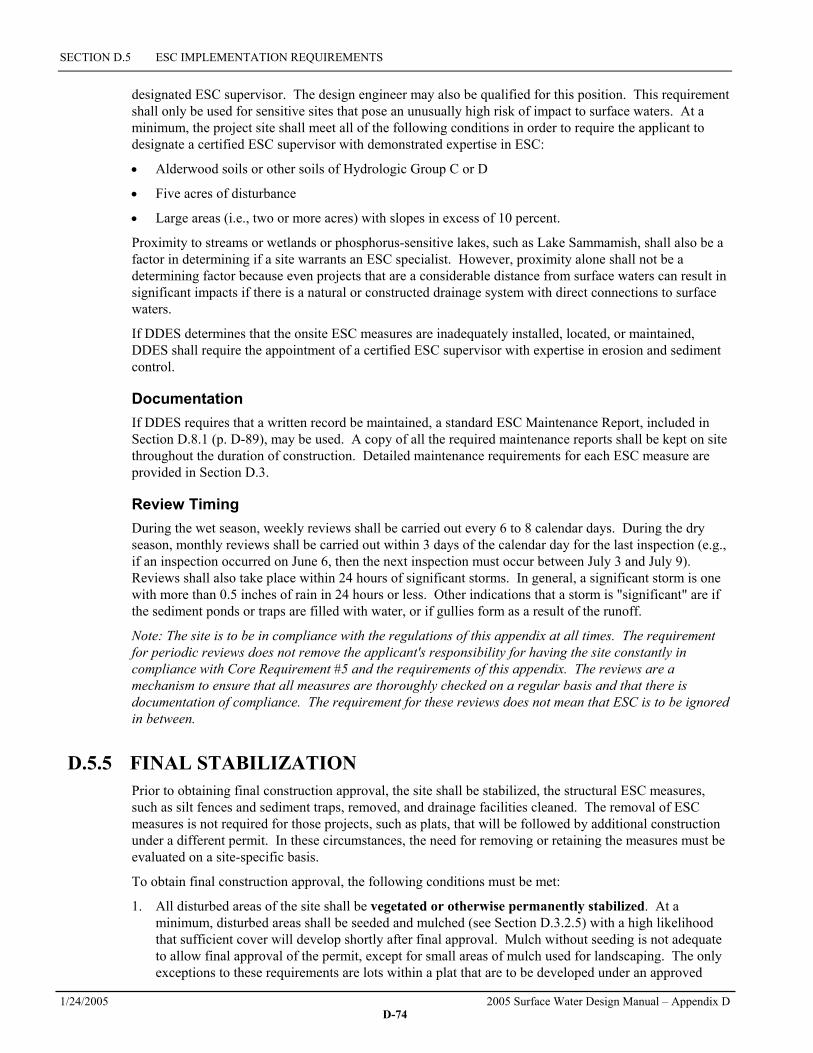
SECTION D.5 ESC IMPLEMENTATION REQUIREMENTS
1/24/2005 2005 Surface Water Design Manual – Appendix D D-74
designated ESC supervisor. The design engineer may also be qualified for this position. This requirement shall only be used for sensitive sites that pose an unusually high risk of impact to surface waters. At a minimum, the project site shall meet all of the following conditions in order to require the applicant to designate a certified ESC supervisor with demonstrated expertise in ESC:
• Alderwood soils or other soils of Hydrologic Group C or D
• Five acres of disturbance
• Large areas (i.e., two or more acres) with slopes in excess of 10 percent.
Proximity to streams or wetlands or phosphorus-sensitive lakes, such as Lake Sammamish, shall also be a factor in determining if a site warrants an ESC specialist. However, proximity alone shall not be a determining factor because even projects that are a considerable distance from surface waters can result in significant impacts if there is a natural or constructed drainage system with direct connections to surface waters.
If DDES determines that the onsite ESC measures are inadequately installed, located, or maintained, DDES shall require the appointment of a certified ESC supervisor with expertise in erosion and sediment control.
Documentation If DDES requires that a written record be maintained, a standard ESC Maintenance Report, included in Section D.8.1 (p. D-89), may be used. A copy of all the required maintenance reports shall be kept on site throughout the duration of construction. Detailed maintenance requirements for each ESC measure are provided in Section D.3.
Review Timing During the wet season, weekly reviews shall be carried out every 6 to 8 calendar days. During the dry season, monthly reviews shall be carried out within 3 days of the calendar day for the last inspection (e.g., if an inspection occurred on June 6, then the next inspection must occur between July 3 and July 9). Reviews shall also take place within 24 hours of significant storms. In general, a significant storm is one with more than 0.5 inches of rain in 24 hours or less. Other indications that a storm is "significant" are if the sediment ponds or traps are filled with water, or if gullies form as a result of the runoff.
Note: The site is to be in compliance with the regulations of this appendix at all times. The requirement for periodic reviews does not remove the applicant's responsibility for having the site constantly in compliance with Core Requirement #5 and the requirements of this appendix. The reviews are a mechanism to ensure that all measures are thoroughly checked on a regular basis and that there is documentation of compliance. The requirement for these reviews does not mean that ESC is to be ignored in between.
D.5.5 FINAL STABILIZATION Prior to obtaining final construction approval, the site shall be stabilized, the structural ESC measures, such as silt fences and sediment traps, removed, and drainage facilities cleaned. The removal of ESC measures is not required for those projects, such as plats, that will be followed by additional construction under a different permit. In these circumstances, the need for removing or retaining the measures must be evaluated on a site-specific basis.
To obtain final construction approval, the following conditions must be met:
1. All disturbed areas of the site shall be vegetated or otherwise permanently stabilized. At a minimum, disturbed areas shall be seeded and mulched (see Section D.3.2.5) with a high likelihood that sufficient cover will develop shortly after final approval. Mulch without seeding is not adequate to allow final approval of the permit, except for small areas of mulch used for landscaping. The only exceptions to these requirements are lots within a plat that are to be developed under an approved

D.5.5 FINAL STABILIZATION
2005 Surface Water Design Manual – Appendix D 1/24/2005 D-75
residential permit immediately following plat approval. In these cases, mulch and/or temporary seeding are adequate for cover.
2. Structural measures such as, but not limited to, silt fences, pipe slope drains, construction entrances, storm drain inlet protection, and sediment traps and ponds shall be removed from the site. Measures that will quickly decompose, such as brush barriers and organic mulches, may be left in place. In the case of silt fences, it may be best to remove fences in conjunction with the seeding, since it may be necessary to bring machinery back in to remove them. This will result in disturbed soils that will again require protection. The DDES inspector must approve an applicant's proposal to remove fencing prior to the establishment of vegetation. In some cases, such as residential building following plat development, it shall be appropriate to leave some or all ESC measures for use during subsequent development. This shall be determined on a site-specific basis.
3. All permanent surface water facilities, including catch basins, manholes, pipes, ditches, channels, flow control facilities, and water quality facilities, shall be cleaned. Any offsite catch basin that required protection during construction (see Section D.3.5.3) shall also be cleaned
4. If only the infrastructure of the site has been developed (e.g., subdivisions and short plats) with building construction to occur under a different permit, then the critical area buffers, Critical Area Tracts, or Critical Area Setback Areas shall be clearly marked as described in Section D.3.1 (p. D-8) in order to alert future buyers and builders.
D.5.6 NPDES REQUIREMENTS As part of the implementation of the National Pollutant Discharge Elimination System (NPDES), projects that will disturb more than one acre for purposes of constructing or allowing for construction a development must apply for coverage under the Washington State Department of Ecology's Baseline General Permit for Stormwater. In general, the erosion control plan required by the Surface Water Design Manual is equivalent to that required by the State through the Stormwater Management Manual for Western Washington (DOE, 2001). The DOE stormwater permit application requires the filing of a Notice of Intent (NOI) at least 30 days prior to the start of construction. The only major requirement of the stormwater permit that is not included in the SWDM is a public notice requirement. Note that this public notice for Ecology's stormwater permit may be published concurrently with other public notices required for permits or SEPA. Contact the Department of Ecology at (360) 407-7156 for complete information on permit thresholds, applications, and requirements.
D.5.7 FOREST PRACTICE PERMIT REQUIREMENTS Projects that will clear more that two acres of forest or 5,000 board feet of timber must apply for a Class IV Special Forest Practice permit from the Washington State Department of Natural Resources (WSDNR). All such clearing is also subject to the State Environmental Policy Act (RCW 43.21C) and will require SEPA review. King County assumes lead agency status for Class IV permits and the application may be consolidated with the associated King County development permit or approval. The permit must be initiated with WSDNR, but will then be transferred over to King County to conduct the SEPA review and grant the permit. Contact the WSDNR for complete information on permit thresholds, applications, and requirements.


KING COUNTY, WASHINGTON, SURFACE WATER DESIGN MANUAL
2005 Surface Water Design Manual – Appendix D 1/24/2005 D-77
D.6 EROSION AND SEDIMENT CONTROL PLANS This section details the specifications and contents for erosion and sediment control (ESC) plans. An ESC plan includes the plan's drawings plus an ESC report, which provides all supporting information and any additional direction necessary for implementing ESC measures and meeting ESC implementation requirements. The ESC plan must be submitted to DDES as part of a complete engineering plan to facilitate proper drainage review. A copy of the approved ESC plan (with ESC report) must be kept on the project site (see Section D.5.1, p. D-71) at all times during the construction phase.
ESC Plan General Specifications The site improvement plan shall be used as the base of the ESC plan. Certain detailed information (e.g., pipe catch basin size, stub-out locations, etc.) that is not relevant may be omitted to make the ESC plan easier to comprehend. At a minimum, the ESC plan shall include all of the information required for the base map of a site improvement plan (see Table 2.3.1A of the Surface Water Design Manual), as well as existing and proposed roads, driveways, parking areas, buildings and drainage facilities, utility corridors not associated with roadways, relevant critical areas8 and associated buffers, and proposed final topography. A smaller scale may be used to provide better comprehension and understanding.
The ESC plan shall generally be designed for proposed topography, not existing topography, since rough grading is usually the first step in site disturbance. The ESC plan shall address all phases of construction (e.g., clearing, grading, installation of utilities, surfacing, and final stabilization). The County may require large, complex projects to phase construction and submit multiple ESC plans for different stages of construction.
The ESC plan outlines the minimum requirements for anticipated site conditions. During construction, ESC plans shall be revised as necessary by the ESC supervisor or as directed by King County to address changing site conditions, unexpected storm events, or non-compliance with the ESC performance criteria in Section D.4.1 (p. D-69).
The following list provides the basic information requirements for the ESC plan. This information shall be consistent with that in Section 8 of the technical information report (TIR) required in the engineering plan submittal (see Section 2.3.1 of the SWDM). Note that the ESC plan's drawings may be simplified by the use of the symbols and codes provided for each ESC measure in Section D.3. In general, the ESC plan's drawings shall be submitted as a separate plan sheet(s). However, there may be some relatively simple projects where providing a separate grading and ESC plan drawing is unnecessary.
1. Identify areas with a high susceptibility to erosion.
2. Provide all details necessary to clearly illustrate the intent of the ESC design.
3. Include ESC measures for all on- and offsite utility construction included in the permit.
4. Specify the construction sequence. The construction sequence shall be specifically written for the proposed project. An example construction sequence is provided in Section D.8.3 (p. D-93).
5. Include standard ESC plan notes (see Section D.8.2, p. D-92) and specify the construction sequence. ESC Notes and a sample construction sequence are provided in the Reference Section.
6. Include an inspection and maintenance program for ESC measures, including designation of a certified ESC supervisor and identification of phone numbers for 24-hour contact.
7. Include the basis and calculations for selection and sizing of ESC measures.
8 Relevant critical areas, for the purposes of drainage review, include aquatic areas, wetlands, flood hazard areas, erosion
hazard areas, landslide hazard areas, steep slope hazard areas, and critical aquifer recharge areas.

SECTION D.6 EROSION AND SEDIMENT CONTROL PLANS
1/24/2005 2005 Surface Water Design Manual – Appendix D D-78
ESC Plan Measure-Specific Information The ESC plan must include the following information specific to applicable ESC measures and implementation requirements. As noted above, this information may need to be updated or revised during the life of the project by the ESC supervisor or as directed by King County.
Clearing Limits 1. Delineate clearing limits (areas to remain uncleared).
2. Provide details sufficient for installation of markings for maintenance of clearing limits.
Cover Measures 1. Specify the type and location of temporary cover measures to be used on site.
2. If more than one type of cover measure is to be used on site, indicate the areas where the different measures shall be used, including steep cut and fill slopes.
3. If the type of cover measures to be used will vary depending on the time of year, soil type, gradient, or some other factor, specify the conditions that control the use of the different measures.
4. Specify the nature and location of permanent cover measures. If a landscaping plan is prepared, this may not be necessary.
5. Specify the approximate amount of cover measures necessary to cover all disturbed areas.
6. If netting, blankets, or plastic sheeting are specified, provide typical details sufficient for installation and maintenance.
7. Specify the mulch types, seed mixes, fertilizers, and soil amendments to be used, as well as the application rate for each item.
8. For surface roughening, describe methods, equipment and areas where surface roughening will be use.
9. If PAM is used on a site, show location(s) and describe application method.
10. When compost blankets are used, show site location, application rates, and the name of the supplier to document that compost meets WAC 173-350-22 standards and meets Grade A quality specifications.
Perimeter Protection 1. Specify the location and type of perimeter protection to be used.
2. Provide typical details sufficient for installation and maintenance of perimeter protection.
3. If a silt fence is to be used, specify the type of fabric.
4. If compost berms or socks are used, documentation must be provide to assure the supplier meets the criteria under WAC 173-350-220 and compost meets Grade A quality standards.
Traffic Area Stabilization 1. Locate the construction entrance(s).
2. Provide typical details sufficient for installation and maintenance of the construction entrance.
3. Locate the construction roads and parking areas.
4. Specify the measure(s) that will be used to create stabilized construction roads and parking areas. Provide sufficient detail to install and maintain.

D.6 EROSION AND SEDIMENT CONTROL PLANS
2005 Surface Water Design Manual – Appendix D 1/24/2005 D-79
5. If a wheel wash or tire bath system will be installed, provide location, typical details for installation and maintenance.
6. Provide a list of dust control products that will be used onsite and the location of potential application areas.
Sediment Retention 1. Show the locations of all sedimentation ponds and traps.
2. Dimension pond berm widths and all inside and outside pond slopes.
3. Indicate the trap/pond storage required and the depth, length, and width dimensions.
4. Provide typical section views throughout the pond and outlet structure.
5. If chemical or electrocoagulation treatment of sediment-laden waters will be used, approval documentation from DOE must be included.
6. Provide details for disposal of contaminated or chemically treated waters (e.g., where Chitosan or CO2 have been used).
7. Include appropriate approval documentation from local sewer districts if contaminated or chemically treated water will be discharged to the sanitary sewer.
8. Provide typical details of the control structure and dewatering mechanism.
9. Detail stabilization techniques for the outlet/inlet protection.
10. Provide details sufficient to install cell dividers.
11. Specify mulch and/or recommended cover of berms and slopes.
12. Indicate the required depth gage with a prominent mark at 1-foot depth for sediment removal.
13. Indicate catch basins that are to be protected.
14. Provide details of the catch basin protection sufficient to install and maintain.
Surface Water Control 1. Locate all pipes, ditches, and interceptor ditches, dikes, and swales that will be used to convey
stormwater.
2. Provide details sufficient to install and maintain all conveyances.
3. Indicate locations of outlet protection and provide detail of protections.
4. Indicate locations and outlets of any possible dewatering systems. Provide details of alternative discharge methods from dewatering systems if adequate infiltration rates cannot be achieved.
5. Indicate the location of any level spreaders and provide details sufficient to install and maintain.
6. Provide all temporary pipe inverts.
7. Provide location and specifications for the interception of runoff from disturbed areas and the conveyance of the runoff to a non-erosive discharge point.
8. Provide locations of rock check dams.
9. Provide details, including front and side sections, of typical rock check dams.
Wet Season Requirements 1. Provide a list of all applicable wet season requirements.

SECTION D.6 EROSION AND SEDIMENT CONTROL PLANS
1/24/2005 2005 Surface Water Design Manual – Appendix D D-80
2. Clearly identify that from October 1st through April 30th, no soils shall be exposed for more than two consecutive working days. Also note that this two-day requirement may be applied at other times of the year if storm events warrant more conservative measures.
3. Clearly identify that exposed soils shall be stabilized at the end of the workday prior to a weekend, holiday, or predicted rain event.
Critical Areas Restrictions 1. Delineate and label the following critical areas, and any applicable buffers, that are on or adjacent
to the project site: aquatic areas, wetlands, flood hazard areas, erosion hazard areas, landslide hazard areas, steep slope hazard areas, and critical aquifer recharge areas.
2. If construction creates disturbed areas within any of the above listed critical areas or associated buffers, specify the type, locations, and details of any measures or other provisions necessary to comply with the critical area restrictions in Appendix D and protect surface waters and steep slopes.

KING COUNTY, WASHINGTON, SURFACE WATER DESIGN MANUAL
2005 Surface Water Design Manual – Appendix D 1/24/2005 D-81
D.7 SMALL SITE ESC Smaller project sites have similar erosion and sediment control (ESC) needs. This section offers a simplified set of requirements for applying erosion and sediment controls to certain smaller project sites and guides the user through the preparation and submittal of a Small Site ESC Plan with the permit application.
D.7.1 INTRODUCTION TO SMALL SITE ESC
What is ESC and Why is it Required for My Site? The basic erosion and sediment control requirement—that sediment shall be prevented to the maximum extent practicable from leaving the site—applies to all projects in King County. All projects, including those with small project sites, are required to use erosion and sediment control (ESC) measures. ESC measures prevent soil erosion during development of the site. The types of measures required for small sites are generally simple to construct and easy to maintain, and with few exceptions do not require engineering or formal design. Examples of such measures include phasing or minimizing clearing, terracing exposed slopes, routing water around exposed soils, and placing straw or other mulching materials and cover exposed soils.
ESC is required because soils eroded from the site are always deposited downstream in pipes, streams, or lakes. Soils deposited in a pipe or channel reduce its capacity to convey flows and can increase the likelihood of flooding. Soils in streams can also clog the gravels that salmon use for spawning. Nutrients associated with soils that reach lakes can upset the chemical balance of the lake, causing excessive growth of algae and decreasing recreational uses such as swimming, boating, and fishing.
Which Projects May Use Small Site Erosion and Sediment Control Requirements? All proposed projects that disturb soil on less than 3 acres and add less than 2,000 square feet of new impervious surface may use the Small Site ESC requirements contained in this section. These projects must apply erosion and sediment control per KCC 16.62 even though they may not be subject to drainage review under the Surface Water Design Manual.
In addition, all proposed projects subject to Small Project Drainage Review as determined in Section 1.1.2.1 of the Surface Water Design Manual, and which disturb soil on less than 3 acres, may use the Small Site ESC requirements contained in this section. These same requirements are contained in Appendix C of the Surface Water Design Manual, which details the drainage requirements for small agricultural and single family residential building or subdivision projects subject to Small Project Drainage Review.
What Will I Be Required To Do? It is the responsibility of both the applicant and the contractor to minimize erosion and the transport of sediment to the greatest extent possible. Erosion and sediment control is a two step process that (1) minimizes the amount of sediment mobilized, and (2) traps any mobilized sediment before it leaves the site.
Examples of erosion controls include use of mulches or other cover materials, marked/minimized clearing, and routing of water around exposed soils. Installation and maintenance of silt fencing is an example of sediment trapping. ESC techniques that are particularly suitable for small sites are described below (Section D.7.2).

SECTION D.7 SMALL SITE ESC
1/24/2005 2005 Surface Water Design Manual – Appendix D D-82
D.7.2 SMALL SITE ESC REQUIREMENTS The following measures will be required on small sites in order to minimize onsite erosion and prevent mobilized sediment from leaving the site:
1. Stabilized construction entrance
2. Mulching or other cover methods
3. Minimized clearing
4. Silt fencing or other perimeter protection
5. Winter (or wet season) stabilization
6. Final stabilization.
Typically, a combination of all of the above measures are required during construction, unless specific site conditions exist that make a particular measure unnecessary, as determined by DDES. Other measures may be allowed or required if these are inappropriate for the project or fail to contain sediment on the project site. A description of other measures that may be needed for successful ESC on some sites, and a more detailed description of those included here, can be found in Section D.3, "ESC Measures" (p. D-7).
The placement and type of proposed ESC measures are shown on a small site ESC plan. Required features of this plan are outlined in Section D.7.3, "Submittal Requirements" (p. D-85).
D.7.2.1 STABILIZED CONSTRUCTION ENTRANCE Construction entrances are stabilized to reduce the amount of sediment transported onto paved roads by motor vehicles or runoff by constructing a stabilized pad of quarry spalls at entrances to construction sites. Construction entrances shall be stabilized wherever traffic will be leaving a construction site and traveling on paved roads or other paved areas within 1,000 feet of the site.
See Section D.3.4.1 (p. D-39) for design and installation specifications and maintenance standards.
D.7.2.2 MULCHING OR OTHER COVER MEASURES The cover measures described below are applicable to small sites.
Mulching The purpose of mulching soils is to provide immediate temporary protection from erosion. Mulch also enhances plant establishment by conserving moisture, holding fertilizer, seed, and topsoil in place, and moderating soil temperatures. There is an enormous variety of mulches that may be used. Only the most common types are discussed in this section.
See Section D.3.2.2 (p. D-13) for conditions of use, design and installation specifications, and maintenance standards.
Nets and Blankets Erosion control nets and blankets are intended to prevent erosion and hold seed and mulch in place on steep slopes and in channels so that vegetation can become well established. In addition, some nets and blankets can be used to permanently reinforce turf to protect drainage ways during high flows. Nets are strands of material woven into an open, but high-tensile strength net (for example, jute matting). Blankets are strands of material that are not tightly woven, but instead form a layer of interlocking fibers, typically held together by a biodegradable or photodegradable netting (for example, excelsior or straw blankets). They generally have lower tensile strength than nets, but cover the ground more completely. Coir (coconut fiber) fabric comes as both nets and blankets.

D.7.2 SMALL SITE ESC REQUIREMENTS
2005 Surface Water Design Manual – Appendix D 1/24/2005 D-83
See Section D.3.2.3 (p. D-15) for conditions of use, design and installation specifications, and maintenance standards.
Plastic Covering Plastic covering provides immediate, short-term erosion protection to slopes and disturbed areas.
See Section D.3.2.4 (p. D-17) for conditions of use, design and installation specifications, and maintenance standards.
D.7.2.3 MARK CLEARING LIMITS / MINIMIZE CLEARING Minimizing clearing is the most effective method of erosion control. Undisturbed vegetation intercepts and slows rainwater. Plant roots hold soil in place, and dead vegetation on the ground acts as a mulch. Clearing limits shall be marked and clearing minimized on any site where significant areas of undisturbed vegetation will be retained.
See Section D.3.1 (p. D-8) for design and installation specifications and maintenance standards.
D.7.2.4 SILT FENCING AND OTHER PERIMETER PROTECTION Perimeter protection to filter sediment from sheetwash shall be located downslope of all disturbed areas and shall be installed prior to upslope grading. The following perimeter protection measures are applicable to small sites.
Silt Fence Use of a silt fence reduces the transport of coarse sediment from a construction site by providing a temporary physical barrier to sediment and reducing the runoff velocities of overland flow. Silt fence may be used downslope of all disturbed areas.
See Section D.3.3.1 (p. D-30) for design and installation specifications and maintenance standards.
Vegetated Strip Vegetated strips reduce the transport of coarse sediment from a construction site by providing a temporary physical barrier to sediment and reducing the runoff velocities of overland flow. Vegetated strips may be used downslope of all disturbed areas.
See Section D.3.3.3 (p. D-34) for design and installation specifications and maintenance standards.
Triangular Silt Dike (Geotextile Encased Check Dam) Triangular silt dikes (TSDs) may be used as check dams, for perimeter protection, for temporary soil stockpile protection, for drop inlet protection, or as a temporary interceptor dike. Silt dikes, if attached to impervious surfaces with tack or other adhesive agent may also be used as temporary wheel wash areas, or concrete washout collection areas.
See Section D.3.3.4 (p. D-34) for conditions of use, design and installation specifications, and maintenance standards.
D.7.2.5 WINTER STABILIZATION
Purpose In order to minimize sediment-laden runoff, as much of the bare and disturbed portions of the site as possible should be covered during any period of precipitation. Once sediment is mobilized, it is much more difficult to effectively control.

SECTION D.7 SMALL SITE ESC
1/24/2005 2005 Surface Water Design Manual – Appendix D D-84
Application All sites require winter stabilization between October 1 and April 30 (the wet season).
Design Specifications During the above time frame, slopes and stockpiles 3H:1V or steeper and with more than 10 feet of vertical rise shall be covered if they are to remain unworked for more than 12 hours. Other disturbed areas shall be covered or mulched according to D.3.2.2 (p. D-13) if they are to remain unworked for more than two days. Cover material sufficient to cover all disturbed areas shall be stockpiled on site at the beginning of the wet season. Areas that are to be left unworked during the winter shall be seeded prior to September 23.
Maintenance The site should be inspected weekly and immediately before, during, and after storms. Cover and other erosion control measures shall be repaired and enhanced as necessary to prevent or minimize sediment runoff and transport.
D.7.2.6 FINAL STABILIZATION
Purpose Final stabilization minimizes sediment-laden runoff from the site after construction has been completed.
Application All sites require final stabilization prior to final construction approval.
Design Specifications Prior to final construction approval, the site shall be stabilized to prevent sediment-laden water from leaving the site after project completion. All disturbed areas of the site shall be vegetated or otherwise permanently stabilized. At a minimum, disturbed areas must be seeded and mulched to ensure that sufficient cover will develop shortly after final approval. Mulch without seeding is adequate for small areas to be landscaped before October 1.
All permanent surface water facilities (including catch basins, manholes, pipes, ditches, channels, flow control facilities, and water quality facilities) impacted by sedimentation during construction must be cleaned.
Maintenance Permanent erosion control is the responsibility of the owner. The site must be kept stabilized using landscaping, mulch, or other measures to prevent sediment-laden water from leaving the site and to prevent sediment from being transported onto adjacent properties and roads.
D.7.3 SUBMITTAL REQUIREMENTS
2005 Surface Water Design Manual – Appendix D 1/24/2005 D-85
D.7.3 SUBMITTAL REQUIREMENTS A Small Site ESC Plan must be submitted for all projects that are eligible to use the Small Site ESC requirements in this section. For projects in Small Project Drainage Review that disturb soil on less than 3 acres, this plan is part of the Small Project Drainage Plan described in the Small Project Drainage Requirements (Appendix C of the Surface Water Design Manual). For other projects, including those that may not be subject to drainage review, this plan would be submitted as directed by DDES. Directions for preparing a Small Site ESC Plan are provided below, and a sample plan is presented in Section D.7.3.3 (p. D-86).
D.7.3.1 SMALL SITE ESC PLAN MAP The Small Site ESC Plan includes information that is routinely collected for a single family residence site plan or a short plat plot plan already required to be submitted with a permit application. One copy of the site plan or plot plan shall be used to show how ESC measures are to be applied to the site to comply with the Small Site ESC requirements. The approximate location and size of clearing limits, rock construction entrance, flow paths, silt fences, etc., should be indicated on the Small Site ESC Plan. Any plan must contain at a minimum the features listed in Section D.7.3.2.
Single family residential projects that qualify for Small Site ESC requirements should use the Residential Site Plan (see DDES Bulletin No. 9, "Obtaining a Residential Building Permit") as the base map for the ESC plan.
Proposed short plats that qualify for Small Project Drainage Review should use the Small Project Drainage Plan (see Small Project Drainage Requirements, detached Appendix C of the Surface Water Design Manual) as a base plan for the ESC plan. All projects subject to Small Project Drainage Review are required to submit these plans and a drainage assessment. If engineering plans are required for a short plat application, they may be used as a base plan for Small Site ESC plans. How the ESC measures are to be applied on the site are added directly to the base map. For more complicated sites, an erosion control professional should be readily able to add Small Site ESC BMPs to the base map with minimal additional effort or expense.
The ESC plans for short plats usually apply only to the site development, since siting of homes on lots created by short plats is done after the short plat is approved (when the home applies for a residential building permit). It is the responsibility of the applicant for a proposed single family residence to show in detail how ESC requirements are met. The applicant is also responsible for Single family residential development is required to comply with the Stormwater Pollution Prevention Manual and KCC 9.12.
D.7.3.2 FEATURES REQUIRED ON SMALL SITE ESC PLANS The Small Site ESC Plan should be drawn on 8-1/2" x 11", 8-1/2" x 14", or 11" x 17" paper (see the sample plan in Figure D.7.3.A, p. D-88), and must include the following information.
Identification 1. Name, address, and phone number of the applicant
2. Scale—use a scale that clearly illustrates drainage features and flow controls (1"=20' is standard engineering scale; minimum acceptable scale is 1"=50')
3. Parcel number
4. North arrow
5. Dimension of all property lines, easements, and building setback lines
6. Street names and existing or proposed property address

SECTION D.7 SMALL SITE ESC
1/24/2005 2005 Surface Water Design Manual – Appendix D D-86
7. Section, township, and range of proposal.
Topography 1. Corner elevations
2. Benchmark (a permanent mark indicating elevation and serving as a reference in the topographic survey)
3. Datum (assumed datum is acceptable in many cases, i.e., fire hydrant base = 100'; datum for projects in or near FEMA floodplains should be NGVD 1929)
4. If over 15% slope: 5-foot contours, top of slope, toe of slope, and any erosion or landslide areas.
Proposed ESC 1. Delineation of proposed clearing limits
2. Type and location of erosion control facilities
3. Location of any significant offsite drainage features within 200 feet of the discharge point(s) for the lot, including streams, lakes, roadside ditches.
Topography/Drainage Features 1. Outline of any stream, wetland, lake, closed depression, or other water feature (including any required
buffer width)
2. Location of all steep slopes, landslide hazard areas, and coal mine hazard areas (including buffers)
3. Location of all existing and proposed drainage easements, ditches, swales, pipes, etc.
4. Location of all critical areas as shown on any recorded critical areas notice on title.
D.7.3.3 SAMPLE SMALL SITE ESC PLAN All sites are required to control erosion and contain sediment. The planning and use of ESC measures will be illustrated for a single family residence. Although the specifics of any lot will differ from those shown here, the process will be similar. The first step in the process is to determine whether the site is eligible to use the Small Site ESC requirements. This evaluation and the following materials are usually included in the drainage assessment that accompanies the Small Site ESC Plan.
The proposed house is to be placed on an existing 1.69-acre lot (see Figure D.7.3.A). Impervious surfaces are the roof, a driveway, and a parking area. The total proposed impervious surface is 6,950 square feet as determined from the residential site plan layout of residence and driveway (the site plan provides the base map for the Small Site ESC Plan). The amount exceeds 2,000 square feet but falls below the 10,000-square-foot limit for Small Project Drainage Review. Therefore, a Small Site ESC Plan is applicable.
The proposal is not in a basin plan area or critical drainage area that might contain clearing limits. However, a portion of a wetland and an erosion hazard area have been identified on the site, and their approximate locations are shown in Figure D.7.3.A. While neither the wetland and its buffer, nor the erosion hazard area would be disturbed during construction, the locations of these critical areas must be verified.
Approximately the southern 2/3 of the site will be cleared. Trees and other native vegetation will be left intact along the northern edge, near the street. Buffers will be maintained around the wetland and erosion hazard areas, respectively. The site slopes towards the street.
In order to prevent erosion and to encourage sedimentation, the following BMPs are used:
1. Clearing will be minimized to the extent possible, and clearing limits will be marked by fencing or other means on the ground.

D.7.3 SUBMITTAL REQUIREMENTS
2005 Surface Water Design Manual – Appendix D 1/24/2005 D-87
2. Water will be routed around the erosion hazard area and around the steep section of the driveway by constructing an interceptor dike or ditch that will intersect and direct water away to the east of the site.
3. Water will be filtered before it reaches the wetland. Silt fencing or other perimeter protection will be placed along slope contours at the limits of clearing in the vicinity of both the wetland and the erosion hazard area.
4. A rocked construction entrance will be placed at the end of the driveway.
5. Mulch will be spread over all cleared areas of the site when they are not being worked. Mulch will consist of air-dried straw and chipped site vegetation. Other cover methods that prevent erosion may also be installed.
The BMPs shown in Figure D.7.3.A must be installed as clearing progresses. For example, the rock construction entrance must be installed as soon as the path for the driveway has been cleared. Additional ESC measures must be installed if the ones proposed above prove insufficient.

SECTION D.7 SMALL SITE ESC
1/24/2005 2005 Surface Water Design Manual – Appendix D D-88
FIGURE D.7.3.A SAMPLE SMALL SITE ESC PLAN

D.8 REFERENCE SECTION
2005 Surface Water Design Manual – Appendix D 1/24/2005 D-89
D.8 REFERENCE SECTION This reference section provides materials useful in developing erosion and sediment control plans and for effectively implementing erosion control measures in the field. In order to make the Erosion and Sediment Control Standards a stand alone booklet, several key components relating to erosion and sediment control found in the Surface Water Design Manual are repeated in this section.
1. ESC maintenance report
2. Standard ESC plan notes
3. Recommended construction sequence
4. References.
D.8.1 ESC MAINTENANCE REPORT DDES may require a written record of all maintenance activities to be kept to demonstrate compliance with the Maintenance Requirements (Section D.5.4). A standard ESC Maintenance Report is provided on the next page. Copies of the ESC Maintenance Report must be kept on site throughout the duration of construction.

SECTION D.8 REFERENCE SECTION
1/24/2005 2005 Surface Water Design Manual – Appendix D D-90
E S C M A I N T E N A N C E R E P O R T
Performed By: ___________________________ Date: ___________________________ Project Name: ___________________________ DDES Permit #: ___________________________ Clearing Limits Damage OK Problem Visible OK Problem Intrusions OK Problem Other OK Problem Mulch Rills/Gullies OK Problem Thickness OK Problem Other OK Problem Nets/Blankets Rills/Gullies OK Problem Ground Contact OK Problem Other OK Problem Plastic Tears/Gaps OK Problem Other OK Problem Seeding Percent Cover OK Problem Rills/Gullies OK Problem Mulch OK Problem Other OK Problem Sodding Grass Health OK Problem Rills/Gullies OK Problem Other OK Problem Perimeter Protection including Silt Fence Damage OK Problem Sediment Build-up OK Problem Concentrated Flow OK Problem Other OK Problem Brush Barrier Damage OK Problem Sediment Build-up OK Problem Concentrated Flow OK Problem Other OK Problem Vegetated Strip Damage OK Problem Sediment Build-up OK Problem Concentrated Flow OK Problem Other OK Problem Construction Entrance Dimensions OK Problem Sediment Tracking OK Problem Vehicle Avoidance OK Problem Other OK Problem Wheel Wash Dimensions OK Problem Sed build up or tracking OK……. Problem Other OK Problem Construction Road Stable Driving Surf. OK Problem Vehicle Avoidance OK Problem Other OK Problem Sediment Trap/Pond

D.8.1 ESC MAINTENANCE REPORT
2005 Surface Water Design Manual – Appendix D 1/24/2005 D-91
Sed. Accumulation OK Problem Overtopping OK Problem Inlet/Outlet Erosion OK Problem Other OK Problem Catch Basin/Inlet Protection Sed. Accumulation OK Problem Damage OK Problem Clogged Filter OK Problem Other OK Problem Interceptor Dike/Swale Damage OK Problem Sed. Accumulation OK Problem Overtopping OK Problem Other OK Problem Pipe Slope Drain Damage OK Problem Inlet/Outlet OK Problem Secure Fittings OK Problem Other OK Problem Ditches Damage OK Problem Sed. Accumulation OK Problem Overtopping OK Problem Other OK Problem Outlet Protection Scour OK Problem Other OK Problem Level Spreader Damage OK Problem Concentrated Flow OK Problem Rills/Gullies OK Problem Sed. Accumulation OK Problem Other OK Problem Dewatering Controls Sediment OK.. Problem Dust Control Palliative applied OK Problem Miscellaneous Wet Season Stockpile OK Problem Other OK Problem Comments: Actions Taken: Problems Unresolved:
SECTION D.8 REFERENCE SECTION
1/24/2005 2005 Surface Water Design Manual – Appendix D D-92
D.8.2 STANDARD ESC PLAN NOTES The standard ESC plan notes must be included on all ESC plans. At the applicant's discretion, notes that in no way apply to the project may be omitted; however, the remaining notes must not be renumbered. For example, if ESC Note #3 were omitted, the remaining notes should be numbered 1, 2, 4, 5, 6, etc.
1. Approval of this erosion and sedimentation control (ESC) plan does not constitute an approval of permanent road or drainage design (e.g., size and location of roads, pipes, restrictors, channels, retention facilities, utilities, etc.).
2. The implementation of these ESC plans and the construction, maintenance, replacement, and upgrading of these ESC facilities is the responsibility of the applicant/ESC supervisor until all construction is approved.
3. The boundaries of the clearing limits shown on this plan shall be clearly flagged by survey tape or fencing, if required, prior to construction (SWDM Appendix D). During the construction period, no disturbance beyond the clearing limits shall be permitted. The clearing limits shall be maintained by the applicant/ESC supervisor for the duration of construction.
4. Stabilized construction entrances shall be installed at the beginning of construction and maintained for the duration of the project. Additional measures, such as constructed wheel wash systems or wash pads, may be required t ensure that all paved areas are kept clean and track out to road right of way does not occur for the duration of the project.
5. The ESC facilities shown on this plan must be constructed prior to or in conjunction with all clearing and grading so as to ensure that the transport of sediment to surface waters, drainage systems, and adjacent properties is minimized.
6. The ESC facilities shown on this plan are the minimum requirements for anticipated site conditions. During the construction period, these ESC facilities shall be upgraded as needed for unexpected storm events and modified to account for changing site conditions (e.g. additional cover measures, additional sump pumps, relocation of ditches and silt fences, perimeter protection etc.) as directed by King County.
7. The ESC facilities shall be inspected daily by the applicant/ESC supervisor and maintained to ensure continued proper functioning. Written records shall be kept of weekly reviews of the ESC facilities.
8. Any areas of exposed soils, including roadway embankments, that will not be disturbed for two consecutive days during the wet season or seven days during the dry season shall be immediately stabilized with the approved ESC methods (e.g., seeding, mulching, plastic covering, etc.).
9. Any area needing ESC measures that do not require immediate attention shall be addressed within seven (7) days.
10. The ESC facilities on inactive sites shall be inspected and maintained a minimum of once a month during the dry season, bi-monthly during the wet season, or within twenty four (24) hours following a storm event.
11. At no time shall more than one (1) foot of sediment be allowed to accumulate within a catch basin. All catch basins and conveyance lines shall be cleaned prior to paving. The cleaning operation shall not flush sediment-laden water into the downstream system.
12. Any permanent retention/detention facility used as a temporary settling basin shall be modified with the necessary erosion control measures and shall provide adequate storage capacity. If the facility is to function ultimately as an infiltration system, the temporary facility must be rough graded so that the bottom and sides are at least three feet above the final grade of the permanent facility.
13. Cover measures will be applied in conformance with Appendix D of the Surface Water Design Manual.

D.8.2 STANDARD ESC PLAN NOTES
2005 Surface Water Design Manual – Appendix D 1/24/2005 D-93
14. Prior to the beginning of the wet season (Oct. 1), all disturbed areas shall be reviewed to identify which ones can be seeded in preparation for the winter rains. Disturbed areas shall be seeded within one week of the beginning of the wet season. A sketch map of those areas to be seeded and those areas to remain uncovered shall be submitted to the DDES inspector.
D.8.3 RECOMMENDED CONSTRUCTION SEQUENCE A detailed construction sequence is needed to ensure that erosion and sediment control measures are applied at the appropriate times. A recommended construction sequence is provided below:
1. Hold the pre-construction meeting.
2. Post sign with name and phone number of ESC supervisor (may be consolidated with the required notice of construction sign).
3. Flag or fence clearing limits.
4. Install catch basin protection, if required.
5. Grade and install construction entrance(s).
6. Install perimeter protection (silt fence, brush barrier, etc.).
7. Construct sediment ponds and traps.
8. Grade and stabilize construction roads.
9. Construct surface water controls (interceptor dikes, pipe slope drains, etc.) simultaneously with clearing and grading for project development.
10. Maintain erosion control measures in accordance with King County standards and manufacturer's recommendations.
11. Relocate erosion control measures, or install new measures so that as site conditions change, the erosion and sediment control is always in accordance with the King County Erosion and Sediment Control Standards.
12. Cover all areas that will be unworked for more than seven days during the dry season or two days during the wet season with straw, wood fiber mulch, compost, plastic sheeting, or equivalent.
13. Stabilize all areas within seven days of reaching final grade.
14. Seed, sod, stabilize, or cover any areas to remain unworked for more than 30 days.
15. Upon completion of the project, stabilize all disturbed areas and remove BMPs if appropriate.
D.8.4 REFERENCES Goldman, S.J., Jackson, K., and Bursztynsky, T.A. 1986. Erosion and Sediment Control Handbook.
McGraw-Hill Book Company, New York, New York.
King County Dept. of Public Works. 1993. Guidelines for Bank Stabilization Projects. Surface Water Management Division, Seattle, Wash.
Metropolitan Washington Council of Governments. 1990. Performance of Current Sediment Control Measures at Maryland Construction Sites. Washington, D.C. Prepared by T.R. Schueler and J. Lugbill.
Horner, R.R., Guedry, J., and Kortenhof, M.H. 1990. Highway Construction Site Erosion and Pollution Control Manual. Washington State Transportation Center, Seattle, Wash. and Washington State Dept. of Transportation, Olympia, Wash. Report No. WA-RD 200.2.