appendix b geotechnical analysis and design of …eng2.lacity.org/whitepoint/final addendum...
TRANSCRIPT

51-1-10052-031
APPENDIX B
GEOTECHNICAL ANALYSIS AND DESIGN
OF GROUND ANCHORS
FOR SLOPE STABILIZATION

51-1-10052-031-R2-ABx/wp/ADY 51-1-10052-031
B-i
APPENDIX B
GEOTECHNICAL ANALYSIS AND DESIGN
OF GROUND ANCHORS
FOR SLOPE STABILIZATION
TABLE OF CONTENTS
FIGURES
Calculation Summary (Sheets 1 thru 30)

CALC. NO: 1
JOB NO: 51-1-10052-031
PROJECT: White Point Landslide Repair, San Pedro, Los Angeles, CA # SHEETS: 30
CLIENT: City of Los Angeles SUBJECT:
Problem:
General Approach / Assumptions:1.
2.
3. Calculate required bonded length of ground anchors using the Post-Tensioning Institute (PTI) procedure.
4.
.Sources of Data and Equations:
1.
2.
3
4
Post-Tensioning Institute (PTI) (1996), "Recommendations for Prestressed Rock and Soil Anchor".
Southern California Earthquake Center (2002), "Recommended Procedures for Implementation of DMG Special Publication 117: Guidelines for Analyzing and Mitigating Landslide Hazards in California".
CALCULATION SUMMARY
Geotechnical analysis and design of ground anchors for slope stabilization.
Review site topographic and boring location plan, boring logs, and lab test data develop at engineering strength parameters for use in analysis.
Ground Anchors for Slope Stabilization (Draft 100% Submission)
Calculate allowable soil bearing pressure for concrete bearing elements for ground anchors using Brinch Hansen's bearing capacity formula for inclined ground surface.
Analyze and design ground anchors for slope stabilization using slope stability analysis program "SLOPE-W".
Coduto, D. P. (1994), "Foundation Design: Principles and Practices".
Sh d il (2012) " i l Add d G h i l 1 hi i d lid " b 19
Shannon and Wilson, Inc (2012), "Final Geotechnical Report, White Point Landslide", August 15, 2012.
5
Summary and Conclusions:Page No. of sheets1 12 13 14 15 Estimate Anchor Bonded Lengths 16 28 816 420 Seismic Slope Displacement Analysis 323 Strand Anchor Structural System (Catalog Cut) 8
Preliminary Calc.: x Draft 100% Submission
Final Calc.: Supercedes Calc. No:
REV. NO. CALCULATION BY DATE CHECKED BY DATE JXM/NXN RTD 2/21/2013
Shannon and Wilson, Inc (2012), "Final Addendum Geotechnical Report No. 1, White Point Landslide", December 19, 2012.
Summary Table - Ultimate Bond Strength between Rock and Grout
Material Strength Summary
2/20/2013
Description
Conceptual Design - Rock Anchors
Cover SheetSummary of Results of Slope Stability Analysis
Slope Stability Analysis using SLOPE-WAnchor Bearing Element Design
Sheet 1 of 30

WHITE POINT LANDSLIDE STABILIZATIONTABLE 2
SUMMARY OF RESULTS OF SLOPE STABILITY ANALYSIS
SHANNON WILSON. INC.
Section Case Number Post‐tensioning StaticH:V Angle of Rows Horizontal Vertical Load per Anchor(1) Factor of Yield Acceleration Max. Equivalent
Safety of Slope, ky (3) Acceleration, kmax
(4) Mobilized (7)
(degrees) (ft) (ft) (kips) (g) (g) With Building(s) No Building
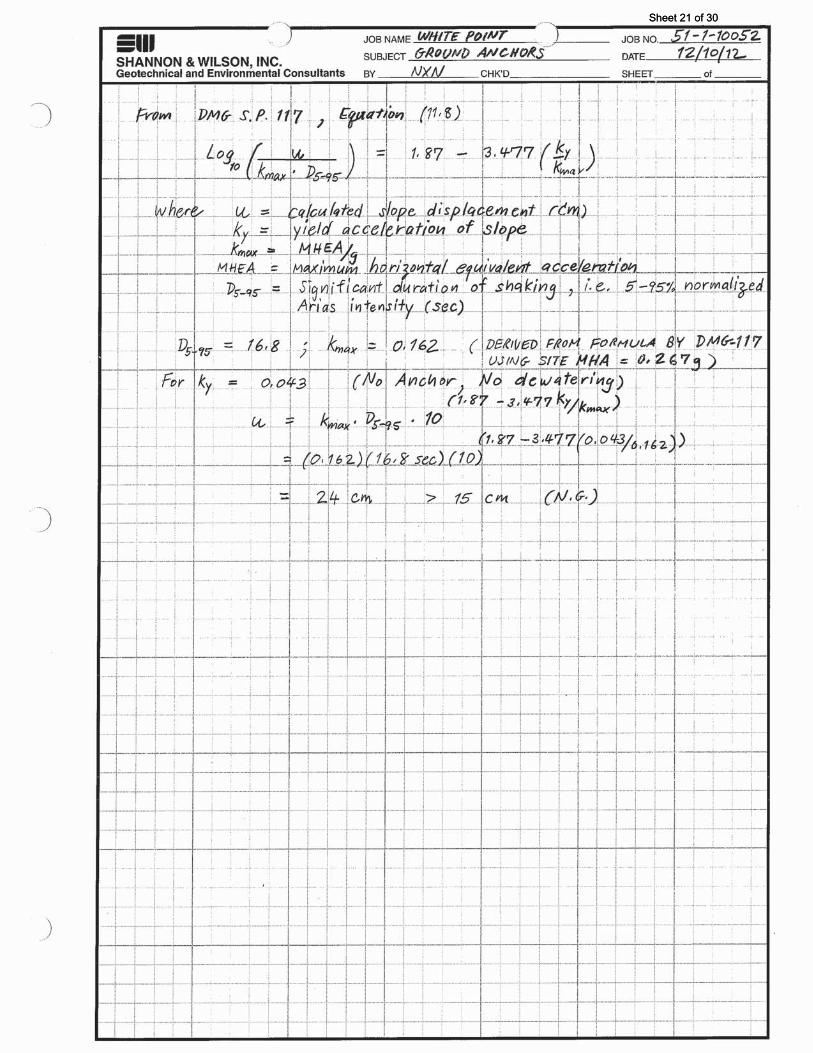
L ‐ L' No slope dewatering/drain pipes(8) ‐ ‐ ‐ ‐ ‐ ‐ 1.3 0.043 0.162 24 6 15
Slope dewatering/drain pipes @ 20 ft ‐ ‐ ‐ ‐ ‐ ‐ 1.48 0.055 0.162 13 6 15
6 ‐ 0.6" dia. seven‐wire strands, ASTM A416, 270 ksi 1 : 1 45 2 20 20 210 1.58 0.063 0.162 9 6 15 (w/ dewatering/drain pipes @ 20 ft) 3 20 20 210 1.64 0.067 0.162 7 6 15
4 20 20 210 1.70 0.072 0.162 6 6 15
13 ‐ 0.6" dia. seven‐wire strands, ASTM A416, 270 ksi 1 : 1 45 2 20 20 458 1.72 0.073 0.162 5.5 6 15 (w/ dewatering/drain pipes @ 20 ft)
M ‐ M' No slope dewatering/drain pipes(8) ‐ ‐ ‐ ‐ ‐ ‐ 1.33 0.042 0.162 25 6 15
Slope dewatering/drain pipes @ 20 ft ‐ ‐ ‐ ‐ ‐ ‐ 1.66 0.068(10) 0.162 7 6 15
6 ‐ 0.6" dia. seven‐wire strands, ASTM A416, 270 ksi 1 : 1 45 2 20 20 211 1.75 0.078(10) 0.162 4 6 15 (w/ dewatering/drain pipes @ 20 ft)
Notes (1) Load is assumed to be less than or equal to 60% of the anchor ultimate capacity.(2) "Recommneded Procedures for Implementation of DMG Spacial Publication 117: Guidelines for Analyzing and Mitigating Landslide Hazards in California" by the Soutern California Earthquake Center (2002) is used for the seismic analysis.(3) The ground acceleration that causes the slope to yield or have a factor of safety of unity against slope failure.(4) Ground acceleration demand(5) Allowable displacement recommended from DMG Special Publication 117.(6) 1 cm = 0.4 inch; 1 inch = 2.54 cm.(7) Slope displacement is estimated using Bray et al (1998) as recommended in DMG Special Publication 117.(8) Hydrostatic pressure is at 30 percent of the height of the near‐vertical tension cracks.(9) GLE method is used to compute the factor of safety against slope failure unless noted.(10) Janbu method is used in lieu of GLE method due to non‐convergent solution.
Rock Anchor Slope Stability Analysis(9)
Allowable (5)Slope Displacement (cm) (6)
Seismic(2)Inclination Spacing
4/16/2013
Sheet 2 of 30

Sheet 3 of 30

Sheet 4 of 30

Sheet 5 of 30

Sheet 6 of 30

Sheet 7 of 30

Sheet 8 of 30

Sheet 9 of 30

Sheet 10 of 30

Sheet 11 of 30

Sheet 12 of 30

Sheet 13 of 30

Sheet 14 of 30

Sheet 15 of 30

Sheet 16 of 30

Sheet 17 of 30

Sheet 18 of 30

Sheet 19 of 30

Sheet 20 of 30
Sheet 21 of 30

Sheet 22 of 30

Sheet 23 of 30

Sheet 24 of 30

Sheet 25 of 30

Sheet 26 of 30

Sheet 27 of 30

Sheet 28 of 30

Sheet 29 of 30

Sheet 30 of 30