appendix b and stability analyses -...
TRANSCRIPT

Stillwater Mining Company Benbow Exploration Portal & Support Facilities
Dean, Montana
Appendix B Design and Stability Analyses
PLAN OF OPERATIONS FOR MINERAL EXPLORATION Benbow Exploration Portal and Support Facilities

www.kn igh tp ieso ld .com
Knight Piésold Ltd. | 1650 Main Street West, North Bay, ON Canada P1B 8G5 | t. +1.705.476.2165 f. +1.705.474.8095
MEMORANDUM
To: Mr. Cole Deringer Date: February 1, 2013
Copy To: Randy Weimer File No.: VA101-110/8-A.01
From: Craig Hall Cont. No.: NB12-00596
Re: Benbow Portal - Portal Pad Stability Summary
Introduction This memo provides a summary of the slope stability analyses completed for the Portal Pad that is required as part of the Benbow Portal development for the Blitz Project. The Portal Pad will provide improved access and a flat work area for equipment and infrastructure required to develop the Portal. Following development of the Portal, the Portal Pad will be utilized to support the on-going mining activities. The proposed Portal Pad layout and evaluated cross sections are shown on Figure 1. Stability analyses were carried out on two sections of the Portal Pad to evaluate the foundation conditions and proposed fill slopes for the Portal Pad construction. The results of analysis were used to confirm that the proposed Portal Pad slopes will satisfy the selected design criteria and minimum required Factors of Safety (FoS) Design Criteria The Portal Pad will generally be constructed as a cut/fill balance with the material excavated from the cut placed and compacted downslope in the fill. The cut and fill material will mainly consist of weathered Chugwater formation bedrock (siltstone and shale) as well as some overburden soils. The fill will be constructed at a 2H:1V slope and the cut slope will be 0.5H:1V. Based on the potential consequences of a slope failure a minimum FoS of 1.5 was considered for long term operations and closure for static loading conditions. A minimum FoS of 1.0 was considered for seismic (pseudo-static) loading conditions. The FoS of 1.0 for seismic loading conditions is an industry accepted value and has been used previously for structures at the Nye Mine and Hertzler Tailings Impoundment. A review of the Montana seismic hazard classification mapping was previously completed to confirm the applicable horizontal acceleration for the nearby Stillwater mine (KPL, 1996). Following the hazard map for a 10% probability of exceed in 50 years, the applicable horizontal acceleration for the site is approximately 0.08 g. In order to account for potential amplification in the foundation soils, a factor of 2 was applied and a peak horizontal ground acceleration of 0.16 g was adopted as the earthquake design ground motion (EDGM) for the seismic loading conditions. Material Parameters Material parameters for the fill and foundation materials have been estimated based on limited site investigation observations, in situ test results, laboratory index test work and published empirical values for similar materials (Carter and Bentley, 1991). The site investigations were completed in 2011 and 2012 and included geotechnical drillholes and test pit excavations. The site investigation and laboratory test work are summarized in the KPL site investigation report (KPL, 2012). Evaluation of near surface bedrock conditions was completed in October 2012 at the drill pad cut slope where Stillwater is in the process of advancing a drillhole along the Portal Pad Alignment. Core photos and drill longs from the drillhole were reviewed in January 2013. The material parameters evaluated in the model are summarized on Table 1 and discussed below.

2 of 4 NB12-00596 February 1, 2013
Portal Pad Fill - The Portal Pad will be constructed from Random Fill that will primarily consist of rockfill composed of compacted weathered shale and siltstone bedrock excavated from the Portal Pad and Access Road cuts with some overburden soils. To account for the variation in the rockfill strength, a relationship of effective friction angle versus normal stress was established following the work by Leps (Leps, 1970). This relationship was used in the analyses to define a normal stress versus shear stress material model for the Portal Pad fill. The unit weight of the Portal Pad fill was estimated based on published values for similar materials (Carter and Bentley, 1991). Overburden - An overburden layer encountered at the Portal Pad area generally consists of a stiff to hard silt layer with some sand and gravel and a few angular cobbles. The average overburden layer thickness was approximately 6 ft and was assumed to overly the entire area even though site investigations were not completed on the steeper slope areas. The Mohr-Coulomb material parameters for the overburden were estimated based on laboratory index test results and published empirical values (Carter and Bentley, 1991) Bedrock - The Portal Pad area is underlain by weathered Chugwater formation bedrock consisting primarily of shale and siltstone. The bedrock surface was estimated based on refusal of the excavation and drilling equipment. Bedrock out crop on surface was observed to be highly weathered with near vertical oriented bedding planes. Hoek Brown criteria was used to develop material strength models for the bedrock. Rock strength values were estimated based on observed site conditions and published empirical values (Hook, Kaiser, and Bawden 1993). A disturbance factor of 0.7 was applied to the cut slope to account for disturbance of the rock mass that may result from excavation. The bedrock quality was observed to improve with depth and has been modelled with an upper and lower layer to reflect this. Bedrock was also modelled as impenetrable for some analyses to simulate a slip surface along the top of the bedrock. Groundwater - The site investigations did not intersect groundwater at the Portal Pad area. To account for potential groundwater influences during the spring thaw and runoff period, the phreatic surface was modelled 20’ below ground surface above the Portal Pad and along the bedrock-overburden interface below the Portal Pad. Methodology Stability analyses were completed using Slope/W© (Geoslope, 2012), a two-dimensional Limit Equilibrium stability analysis software package. Analyses were completed to account for the proposed Portal Pad configuration and estimated material strength parameters. The Morgenstern-Price Limit-Equilibrium method was utilized for the analyses. The overall slope stability assessment was completed based on two cross sections to evaluate the variation in the existing slopes at the Portal Pad area. The section locations are shown on Figure 1. Section 1 has an existing overall slope angle of approximately 4.2H:1V and Section 2 has an existing slope angle of approximately 2.6H:1V. Section 2 was modelled with a continuous and discontinuous overburden layer. To simulate a discontinuous overburden layer, overburden was removed from below the lower ¼ of the Portal Pad fill. The phreatic surface was modelled along the bedrock-overburden interface. The slope stability analysis models are illustrated on Figures 2 and 3. Results The results of the analyses are summarized on Table 2 and illustrated on Figures 4 to 12. The stability analyses indicate the following: Section 1 The results for Section 1 are shown on Figures 4 through 8. The analyses indicate that the minimum acceptable FoS is achievable under both static and seismic
(pseudo-static) loading conditions with an elevated phreatic surface along the bedrock-overburden interface.

3 of 4 NB12-00596 February 1, 2013
Potential deep seated slip surfaces projected through the Chugwater formation bedrock foundation, under both static and seismic (pseudo-static) loading conditions, result in higher factors of safety then slip surfaces along the bedrock surface.
Analysis of the cut slope in bedrock above the Portal Pad indicates that the FoS against slope failure satisfies the design criteria under both static and seismic loading conditions.
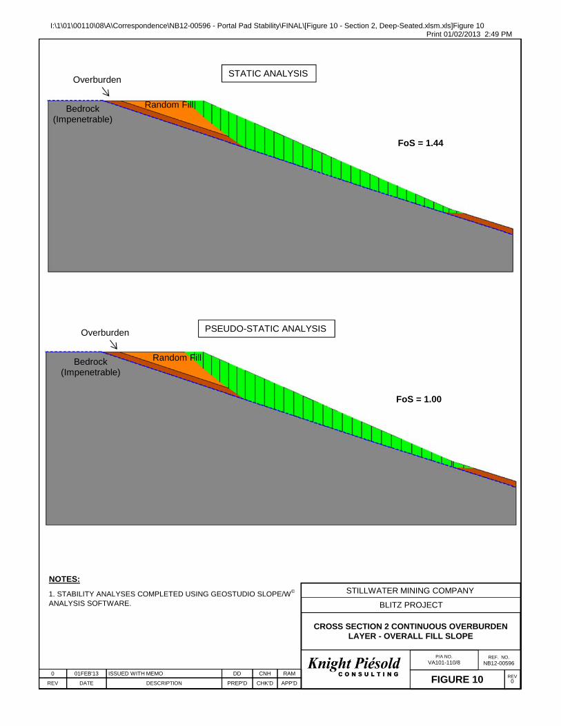
Section 2 The results for Section 2 are included on Figures 9 and 10 for a continuous overburden layer. The results
for Section 2 with a discontinuous overburden layer are included on Figures 11 and 12. The minimum acceptable FoS are not achievable under static or seismic (pseudo-static) loading conditions
with the continuous overburden layer and an elevated phreatic surface. The minimum acceptable FoS are achievable under all loading conditions with a discontinuous overburden
layer and an elevated phreatic surface. Conclusions and Recommendations The following conclusions and recommendations are provided based on the stability analyses completed on two cross sections for the Benbow Portal Pad. Section 1 Analyses completed on Section 1 indicated that in areas with shallower existing slopes the Portal Pad Fill
constructed directly over a continuous overburden layer will meet the minimum FoS for the cases analysed. Analysis of overall and deep seated circular failures through the underlying bedrock result in a high FoS well
above the design criteria. Analysis of the cut slope above the Portal Pad indicates that the minimum FoS will be achieved for slip
surfaces developing through the bedrock. Section 2 Analyses completed on Section 2 location indicate that at the steeper existing slope areas the Portal Pad fill
constructed directly over a continuous overburden layer will not meet the minimum FoS requirements for static loading conditions, however, for the case where the overburden layer has been excavated from below the lower ¼ of the slope, minimum required FoS is achievable.
The depth of the overburden present at the steeper slope areas remains to be confirmed and should be evaluated during the foundation preparation work.
During construction, if a thin overburden layer (less than 2 ft) is noted to be present on the steeper slope sections, the overburden can be effectively removed during the foundation preparation work. The foundation preparation work would include stripping and grubbing of the surface soils and keying into underlying bedrock below the overburden.
If a thicker overburden layer (greater than 2 ft) is observed to be present on the steeper slope areas, removal of the overburden will be required prior to fill placement. It is proposed that the removed overburden would be blended into the rockfill placement to maintain the cut/fill balance for the Portal Pad fill.
Construction A detailed evaluation of the prepared foundation conditions is required to be completed by a qualified
Geotechnical Engineer during construction prior to commencing the fill placement activities. The evaluation is needed to confirm the results of the stability analysis and that suitable foundation conditions exist in the area where fill be placed.
The cut slope above the Portal Pad will be excavated in weather bedrock. There is a potential for ravelling of loose rock from the cut face to result in unsafe working conditions on the Portal Pad. It is expected that some level of surface improvement to the cut slope will be required which may include installation of wire mesh, rock bolts and shotcrete. An evaluation of the cut slope by a qualified Engineer should be completed to confirm the design assumptions and if any slope improvements are required.


TABLE 1
STILLWATER MINING COMPANYBLITZ PROJECT
BENBOW PORTAL - PORTAL PAD STABILITY SUMMARYSUMMARY OF MATERIAL PARAMETERS
Print Feb/01/13 14:53:33
Unit Weight Cohesion Friction UCS
(pcf) (psi) (Degrees) (psi)
Random Fill 125 0 30-44 Shear-Normal Function
Overburden 115 0 32 Mohr-Coulomb
Upper Bedrock 170 6 2,900 25 Hoek-Brown
Lower Bedrock 170 6 2,900 35 Hoek-BrownI:\1\01\00110\08\A\Correspondence\NB12-00596 - Portal Pad Stability\FINAL\[Table 1 - Material Parameters_.xlsx]Table 1
NOTES:
ModelMaterial
1. MATERIAL PARAMETERS ARE BASED ON INFORMATION OBTAINED FROM SITE INVESTIGATIONS LABORATORY TESTING AND PUBLISHED EMPERICAL VALUES FOR SIMILAR SOILS AND ROCK.
mi GSI
0 01FEB'13 JAM CNHISSUED WITH MEMO NB12-00596 RAMDATE DESCRIPTION PREP'D CHK'D APP'DREV
Page 1 of 1

Pad Elevation Toe Elevation
(ft) (ft) Static (Required = 1.5)
Psuedo-Static (Required = 1.0)
Lower Fill Slope Impenetrable 2H:1V 6481 6404 1.61 1.13
Overall Fill Slope Impenetrable 2H:1V 6481 6404 1.65 1.15
Overall Slope Deep Seated Penetrable 2H:1V 6481 6404 3.11 1.87
Portal Pad Deep Seated Penetrable 2H:1V 6481 6404 3.89 2.16
Cut Slope Penetrable 2H:1V 6481 6404 1.52 1.43
Lower Fill Slope Impenetrable 2H:1V 6480 6366 1.42 1.00
Overall Fill Slope Impenetrable 2H:1V 6480 6366 1.44 1.00
Lower Fill Slope Impenetrable 2H:1V 6480 6366 1.87 1.30
Overall Fill Slope Impenetrable 2H:1V 6480 6366 1.60 1.12
NOTES:
ContinuousNo.1
FoSBedrock
No.2
1. PSEUDO STATIC CONDITIONS EVALUATED FOR THE MAXIMUM DESIGN EARTHQUAKE (MDE) WITH A MAGNITUDE OF 7.0 AND A MAXIMUM FIRM GROUND ACCELERATION OF 0.16g.
Overall SlopeOverburden LayerCross Section
Continuous
Discontinuous
I:\1\01\00110\08\A\Correspondence\NB12-00596 - Portal Pad Stability\FINAL\[Table 2 - Slope Stability Results Summary_MGW.xlsx]FOS results
Scenario
Print Feb/01/13 14:55:03
TABLE 2
STILLWATER MINING COMPANYBLITZ PROJECT
BENBOW PORTAL - PORTAL PAD STABILITY SUMMARYSLOPE STABILITY RESULTS
0 01FEB'13 JAM CNHISSUED WITH MEMO NB12-00596 RAMDATE DESCRIPTION PREP'D CHK'D APP'DREV
Page 1 of 1

1 930 750
E
1 931 000
E
1 931 250
E
504 500 N
504 250 N
504 000 N
503 750 N
0
+
0
0
1+
00
2+
00
3+
00
4+
00
5+
00
5+
20
0
+
0
0
1
+
0
0
2
+
0
0
2
+
8
0
EL
EV
AT
IO
N (ft)
6390
6400
6410
6420
6430
6440
6450
6460
6470
6480
6490
6500
6510
6520
6530
6540
6550
6560
0+00 0+50 1+00 1+50 2+00 2+50 3+00 3+50 4+00 4+50 5+00 5+25
6390
6400
6410
6420
6430
6440
6450
6460
6470
6480
6490
6500
6510
6520
6530
6540
6550
6560
EL
EV
AT
IO
N (ft)
STREAM/CREEK
NOTES:
1. COORDINATE GRID IS SMC 6000.
2. PLAN BASED ON INFORMATION PROVIDED BY STILLWATER MINING COMPANY.
3. ORIGINAL GROUND CONTOUR INTERVAL IS 5 FEET.
4. SAFETY BERM DETAILS TO BE FIELD FIT.
5. STORMWATER COLLECTION POND TO BE LOCATED TO SUITE SITE CONDITIONS.
EXTENTS OF DETAILED MAPPING
EXTENTS OF
DETAILED
MAPPING
EXTENTS OF
DETAILED
MAPPING
N
STORMWATER
RUNOFF
DITCH
STORMWATER
COLLECTION POND
(SEE NOTE 5)
PORTAL
1
2
2
STORMWATER
RUNOFF
DITCH
ORIGINAL
GROUND
SURFACE
1
0.5
2
1
LEGEND:
RANDOM
FILL
APPROXIMATE
PREPARED
FOUNDATION
SECTION 11
PORTAL PAD
SCALE B
A
0 ft40 40 80 120 160 200
SCALE B
EXCAVATION
LIMITS
FINISHED
GRADE
PORTAL PAD
ACCESS ROAD
DITCH
SECTION 22
PORTAL PAD
SCALE B
2
1
ORIGINAL
GROUND
SURFACE
2
DRILL PAD TRAIL
DRILL PAD
TRAIL
REV
P/A NO. REF NO.
REV DATE DESCRIPTION DRAWNDESIGNED CHK'D APP'D
STILLWATER MINING COMPANY
BLITZ PROJECT
BENBOW PORTAL PORTAL PADPLAN AND SECTIONS
VA101-110/8 NB12-00596
0FIGURE 1
0 ft50 50 100 150 200 250
SCALE A
PLAN
SCALE A
0 01FEB'13 ISSUED WITH MEMO JAM MMD CNH RAM
SAFETY BERM
SAFETY BERM
1
RANDOM
FILL
FINISHED
GRADE
1
2.6
1
4.2
EL
EV
AT
IO
N (ft)
EL
EV
AT
IO
N (ft)
6370
6380
6390
6400
6410
6420
6430
6440
6450
6460
6470
6480
6490
6500
6370
6380
6390
6400
6410
6420
6430
6440
6450
6460
6470
6480
6490
6500
0+000+50 1+00 1+50
2+00 2+50
2+80
APPROXIMATE
PREPARED
FOUNDATION
(OVERALL EXISTING SLOPE)
(OVERALL EXISTING SLOPE)
SAFETY BERM
SAFETY BERM

I:\1\01\00110\08\A\Correspondence\NB12-00596 - Portal Pad Stability\FINAL\[Figure 2 - Section 1 Model.xlsm.xls]Figure 2 Print 01/02/2013 2:18 PM
NOTES:
1. STABILITY ANALYSES COMPLETED USING GEOSTUDIO SLOPE/W©
ANALYSIS SOFTWARE.
0 01FEB'13 ISSUED WITH MEMO DD CNH RAM
DATE DESCRIPTION PREP'D CHK'D APP'DREV
CROSS SECTION 1STABILITY ANALYSIS MODEL
FIGURE 2
STILLWATER MINING COMPANY
BLITZ PROJECT
REV0
P/A NO. VA101-110/8
REF. NO.NB12-00596
CROSS SECTION 1 - CONTINUOUS OVERBURDEN LAYER
2H:1V
Random FillBedrock
Overburden
4.2H:1V

I:\1\01\00110\08\A\Correspondence\NB12-00596 - Portal Pad Stability\FINAL\[Figure 3 - Section 2 Models.xlsm.xls]Figure 3 Print 01/02/2013 2:45 PM
NOTES:
1. STABILITY ANALYSES COMPLETED USING GEOSTUDIO SLOPE/W©
ANALYSIS SOFTWARE.
0 01FEB'13 ISSUED WITH MEMO DD CNH RAM
DATE DESCRIPTION PREP'D CHK'D APP'DREV
CROSS SECTION 2STABILITY ANALYSIS MODELS
FIGURE 3
STILLWATER MINING COMPANY
BLITZ PROJECT
REV0
P/A NO. VA101-110/8
REF. NO.NB12-00596
CROSS SECTION 2 - DISCONTINUOUS OVERBURDEN LAYER
2H:1V
Random FillBedrock (Impenetrable)
Overburden
2.6H:1V
CROSS SECTION 2 - CONTINUOUS OVERBURDEN LAYER
2H:1V
Random FillBedrock (Impenetrable)
Overburden
2.6H:1V

I:\1\01\00110\08\A\Correspondence\NB12-00596 - Portal Pad Stability\FINAL\[Figure 4 - Section 1, Mid-Slope.xlsm.xls]Figure 4 Print 01/02/2013 2:45 PM
NOTES:
1. STABILITY ANALYSES COMPLETED USING GEOSTUDIO SLOPE/W©
ANALYSIS SOFTWARE.
0 01FEB'13 ISSUED WITH MEMO DD CNH RAM
DATE DESCRIPTION PREP'D CHK'D APP'DREV
CROSS SECTION 1 LOWER FILL SLOPE
FIGURE 4
STILLWATER MINING COMPANY
BLITZ PROJECT
REV0
P/A NO. VA101-110/8
REF. NO.NB12-00596
STATIC ANALYSIS
PSEUDO-STATIC ANALYSIS
FoS = 1.61
FoS = 1.13
Random FillBedrock (Impenetrable)
Overburden
Random FillBedrock (Impenetrable)
Overburden

I:\1\01\00110\08\A\Correspondence\NB12-00596 - Portal Pad Stability\FINAL\[Figure 5 - Section 1, Fill Slope Crest.xlsm.xls]Figure 5 Print 01/02/2013 2:46 PM
NOTES:
1. STABILITY ANALYSES COMPLETED USING GEOSTUDIO SLOPE/W©
ANALYSIS SOFTWARE.
0 01FEB'13 ISSUED WITH MEMO DD CNH RAM
DATE DESCRIPTION PREP'D CHK'D APP'DREV
CROSS SECTION 1 OVERALL FILL SLOPE
FIGURE 5
STILLWATER MINING COMPANY
BLITZ PROJECT
REV0
P/A NO. VA101-110/8
REF. NO.NB12-00596
STATIC ANALYSIS
PSEUDO-STATIC ANALYSIS
FoS = 1.65
FoS = 1.15
Random FillBedrock (Impenetrable)
Overburden
Random FillBedrock (Impenetrable)
Overburden

I:\1\01\00110\08\A\Correspondence\NB12-00596 - Portal Pad Stability\FINAL\[Figure 6 - Section 1 Overall.xlsm.xls]Figure 6 Print 01/02/2013 2:20 PM
NOTES:
1. STABILITY ANALYSES COMPLETED USING GEOSTUDIO SLOPE/W©
ANALYSIS SOFTWARE.
1.875
3.115
0 01FEB'13 ISSUED WITH MEMO MGW JAM RAM
DATE DESCRIPTION PREP'D CHK'D APP'DREV
CROSS SECTION 1OVERALL SLOPE DEEP SEATED
FIGURE 6
STILLWATER MINING COMPANY
BLITZ PROJECT
REV0
P/A NO. VA101-110/8
REF. NO.NB12-00596
PSEUDO-STATIC ANALYSIS
STATIC ANALYSIS
Random Fill
Disturbed Zone (D=0.7)
Overburden
Lower Bedrock (D=0)
Lower Bedrock (D=0)
FoS = 1.87
Upper Bedrock (D=0)
Random Fill
Disturbed Zone (D=0.7)
Overburden
Upper Bedrock (D=0)
FoS = 3.11

I:\1\01\00110\08\A\Correspondence\NB12-00596 - Portal Pad Stability\FINAL\[Figure 7 - Section 1 Deep-Seated.xlsm.xls]Figure 7 Print 01/02/2013 2:46 PM
NOTES:
1. STABILITY ANALYSES COMPLETED USING GEOSTUDIO SLOPE/W©
ANALYSIS SOFTWARE.
2.159
3.888
0 01FEB'13 ISSUED WITH MEMO MGW JAM RAM
DATE DESCRIPTION PREP'D CHK'D APP'DREV
CROSS SECTION 1PORTAL PAD DEEP SEATED
FIGURE 7
STILLWATER MINING COMPANY
BLITZ PROJECT
REV0
P/A NO. VA101-110/8
REF. NO.NB12-00596
PSEUDO-STATIC ANALYSIS
STATIC ANALYSIS
FoS = 3.89
FoS = 2.16
Lower Bedrock (D=0)
Random Fill
Disturbed Zone (D=0.7)
OverburdenUpper Bedrock (D=0)
Lower Bedrock (D=0)
Random Fill
Disturbed Zone (D=0.7)
OverburdenUpper Bedrock (D=0)

I:\1\01\00110\08\A\Correspondence\NB12-00596 - Portal Pad Stability\FINAL\[Figure 8 - Section 1 Cut Slope.xlsm.xls]Figure 8 Print 01/02/2013 2:47 PM
NOTES:
1. STABILITY ANALYSES COMPLETED USING GEOSTUDIO SLOPE/W©
ANALYSIS SOFTWARE.
0 01FEB'13 ISSUED WITH MEMO MGW JAM RAM
DATE DESCRIPTION PREP'D CHK'D APP'DREV
CROSS SECTION 1CUT SLOPE
FIGURE 8
STILLWATER MINING COMPANY
BLITZ PROJECT
REV0
P/A NO. VA101-110/8
REF. NO.NB12-00596
PSEUDO-STATIC ANALYSIS
STATIC ANALYSIS
FoS = 1.52
FoS = 1.43
Lower Bedrock (D=0)
Random Fill
Disturbed Zone (D=0.7)
Upper Bedrock (D=0)
Lower Bedrock (D=0)
Disturbed Zone (D=0.7)
Overburden
Upper Bedrock (D=0)
Overburden
Random Fill

I:\1\01\00110\08\A\Correspondence\NB12-00596 - Portal Pad Stability\FINAL\[Figure 9 - Section 2, Mid-Slope.xlsm.xls]Figure 9Print 01/02/2013 2:49 PM
NOTES:
1. STABILITY ANALYSES COMPLETED USING GEOSTUDIO SLOPE/W©
ANALYSIS SOFTWARE.
0 01FEB'13 ISSUED WITH MEMO DD CNH RAM
DATE DESCRIPTION PREP'D CHK'D APP'DREV
CROSS SECTION 2 - CONTINUOUS OVERBURDEN LAYER - LOWER FILL SLOPE
FIGURE 9
STILLWATER MINING COMPANY
BLITZ PROJECT
REV0
P/A NO. VA101-110/8
REF. NO.NB12-00596
STATIC ANALYSIS
PSEUDO-STATIC ANALYSIS
FoS = 1.42
FoS = 1.00
Random FillBedrock (Impenetrable)
Overburden
Random FillBedrock (Impenetrable)
Overburden
I:\1\01\00110\08\A\Correspondence\NB12-00596 - Portal Pad Stability\FINAL\[Figure 10 - Section 2, Deep-Seated.xlsm.xls]Figure 10Print 01/02/2013 2:49 PM
NOTES:
1. STABILITY ANALYSES COMPLETED USING GEOSTUDIO SLOPE/W©
ANALYSIS SOFTWARE.
0 01FEB'13 ISSUED WITH MEMO DD CNH RAM
DATE DESCRIPTION PREP'D CHK'D APP'DREV
CROSS SECTION 2 CONTINUOUS OVERBURDEN LAYER - OVERALL FILL SLOPE
FIGURE 10
STILLWATER MINING COMPANY
BLITZ PROJECT
REV0
P/A NO. VA101-110/8
REF. NO.NB12-00596
STATIC ANALYSIS
PSEUDO-STATIC ANALYSIS
FoS = 1.44
FoS = 1.00
Random FillBedrock (Impenetrable)
Overburden
Random FillBedrock (Impenetrable)
Overburden

I:\1\01\00110\08\A\Correspondence\NB12-00596 - Portal Pad Stability\FINAL\[Figure 11 - Section 2, Mid-Slope.xlsm.xls]Figure 11Print 01/02/2013 2:44 PM
NOTES:
1. STABILITY ANALYSES COMPLETED USING GEOSTUDIO SLOPE/W©
ANALYSIS SOFTWARE.
0 01FEB'13 ISSUED WITH MEMO DD CNH RAM
DATE DESCRIPTION PREP'D CHK'D APP'DREV
CROSS SECTION 2 DISCONTINUOUS OVERBURDEN LAYER - LOWER FILL SLOPE
FIGURE 11
STILLWATER MINING COMPANY
BLITZ PROJECT
REV0
P/A NO. VA101-110/8
REF. NO.NB12-00596
STATIC ANALYSIS
PSEUDO-STATIC ANALYSIS
FoS = 1.87
FoS = 1.30
Random FillBedrock (Impenetrable)
Overburden
Random FillBedrock (Impenetrable)
Overburden

I:\1\01\00110\08\A\Correspondence\NB12-00596 - Portal Pad Stability\FINAL\[Figure 12 - Section 2, Deep-Seated.xlsm.xls]Figure 9Print 01/02/2013 2:44 PM
NOTES:
1. STABILITY ANALYSES COMPLETED USING GEOSTUDIO SLOPE/W©
ANALYSIS SOFTWARE.
0 01FEB'13 ISSUED WITH MEMO DD CNH RAM
DATE DESCRIPTION PREP'D CHK'D APP'DREV
CROSS SECTION 2 DISCONTINUOUS OVERBURDEN LAYER - OVERALL FILL SLOPE
FIGURE 12
STILLWATER MINING COMPANY
BLITZ PROJECT
REV0
P/A NO. VA101-110/8
REF. NO.NB12-00596
STATIC ANALYSIS
PSEUDO-STATIC ANALYSIS
FoS = 1.60
FoS = 1.12
Random FillBedrock (Impenetrable)
Overburden
Random FillBedrock (Impenetrable)
Overburden

www.kn igh tp ieso ld .com
Knight Piésold Ltd. | 1650 Main Street West, North Bay, ON Canada P1B 8G5 | t. +1.705.476.2165 f. +1.705.474.8095
MEMORANDUM
To: Cole Deringer Date: January 31, 2013
Copy To: Randy Weimer, Ken Embree File No.: VA101-110/8-A.01
From: Alex McIntyre Cont. No.: NB12-00474
Re: Waste Rock Storage Area Stability Analysis
Introduction This memo provides a summary of the stability analyses completed for the Waste Rock Storage Area (WRSA) that is part of the proposed Benbow Portal development for Stillwater Mining Company’s Blitz Project. The analyses were carried out to confirm overall stability of the ultimate WRSA. General The WRSA will be located to the west of the Benbow Portal and to the southwest of access road USFS 2414, as shown on Figure 1. The layout for the WRSA has been based on the projected waste rock production schedule provided by Stillwater. The final storage area will be constructed to El. 6290 ft. and the overall height will be approximately 150 ft. The downstream slope of the WRSA will be approximately 2.5H:1V. An underdrain layer will be constructed below the WRSA to collect seepage and runoff water. The underdrain layer will cover the entire WRSA footprint and will consist of drainage sand and gravel, non-woven geotextile, textured HDPE geomembrane and collection pipework. Design Criteria The WRSA will remain in place following closure of the facility. As such, it must be stable during long term conditions with a Factor of Safety (FoS) greater than 1.5 for static loading conditions. A FoS of 1.0 is required for seismic loading conditions. A review of the Montana seismic hazard classification mapping was previously completed to confirm the applicable horizontal acceleration for the nearby Stillwater mine (KPL, 1996). Following the hazard map for a 10% probability of exceedance in 50 years, the applicable horizontal acceleration for the site is approximately 0.08 g. In order to account for potential amplification in the foundation soils, a factor of 2 was applied and a horizontal acceleration of 0.16 g was adopted for the seismic loading conditions. The design criteria adopted for these analyses are summarized as follows:
Loading Conditions Design Criteria Operations and Closure (Long Term) Minimum Acceptable FoS = 1.5
Seismic (Pseudo-Static) Minimum Acceptable FoS = 1.0
Maximum Design Ground Acceleration 0.16g

2 of 3 NB12-00474 January 31, 2012
Material Parameters Rockfill stored in the WRSA will consist of waste rock excavated from the Benbow Portal development. The WRSA will be constructed with an underdrain consisting of processed materials and geosynthetics. Site investigations were carried out by Knight Piésold Ltd. (KPL) during 2011 and 2012 to characterize the foundation conditions of the WRSA. Laboratory index testwork was completed on select samples to confirm the foundation soil properties. Geotechnical design parameters were estimated based on site investigations, laboratory testing, and typical values. The design parameters are summarized on Table 1 and discussed below. Mine Waste Rock The WRSA will be comprised of Run of Mine (ROM) waste rock placed with nominal compaction. ROM waste rock produced during the initial excavation will be comprised of shales and siltstones from the Chugwater formation. ROM waste rock produced from the excavation at depth will be comprised of intrusive ultra mafic rocks from the Stillwater complex. To account for the variation in the rockfill strength, a relationship of effective friction angle (Φ’) versus normal stress (σn) was established following the work by Leps (1970). This relationship was used in the analyses to define a normal stress (σn) versus shear stress (τ) material model for the ROM waste rock. The ROM waste rock has been modelled based on the lower bound strength published by Leps. The unit weight of the Chugwater formation and Stillwater complex ROM waste rock has been based on past experience at the Nye mine site. Drainage Layer Seepage from the ROM waste rock will be collected via an underdrain layer which will be constructed over the entire footprint of the WRSA. The underdrain layer will consist of sand and gravel placed over non-woven geotextile and textured HDPE geomembrane placed over the prepared subgrade. The material parameters for the drainage layer were estimated based on published empirical values (Carter and Bentley 1991) for similar soils and the frictional properties of the textured HDPE geomembrane. Based on the results of these analyses, it was determined that a textured HDPE will be required (opposed to a smooth HDPE liner). Foundation The foundation soils consist of non-cohesive silty sand. Following stripping and grubbing activities, foundation soils will be graded and proof rolled to prepare the area for the underdrain layer. Limited strength testing data is available for the overburden in the vicinity of the WRSA. Strength parameters for the analysis were estimated based on empirical values published for similar soils (Carter and Bentley 1991). In order to minimize the potential for excess pore water pressure build up in the foundation, a geotextile wrapped foundation drain will be installed below the underdrain layer geomembrane along the base of the drainage Methodology Stability analyses were completed using the two-dimensional Limit Equilibrium stability analysis software package SLOPE/W©. These models incorporated the proposed configuration and estimated strength parameters of the foundation soils and underdrain layer. In these analyses the projected slip surfaces were determined for both a failure through the foundation soils and along the underdrain layers. The final height (El. 6290 ft.) of the WRSA section was selected for the analysis since it represents the largest potential loading conditions during operations and after closure. The Morgenstern-Price method was used to estimate the FoS for both static and pseudo static (seismic) loading conditions as shown on Figure 2.


Print Jan/31/13 9:46:08
Material Bulk Unit Effective Friction Material
Weight Cohesion Angle Model
(pcf) (psf) (deg.)
ROM Waste Rock - Stillwater Formation 145 0 35-53 Shear-Normal Function
ROM Waste Rock - Chugwater Formation 135 0 35-53 Shear-Normal Function
Foundation Soils 120 0 27 Mohr-Coulomb
Underdrain Layer [2] 125 0 25 Mohr-Coulomb
BedrockI:\1\01\00110\08\A\Correspondence\NB12-00474 - Waste Rock Storage Area Stability\[Table 1 - Material Parameters.xls]Table 1
NOTES:1. ROM WASTE ROCK STRENGTH HAS BEEN BASED ON LOWER BOUND ROCKFILL STRENGTH RELATIONSHIPS PUBLISHED BY LEPS 1970.2. UNDERDRAIN STRENGTH IS BASED ON THE LESSER OF THE GEOMEMBRANE FRICTION ANGLE OR THE ESTIMATED FRICTION ANGLE OF THE DRAINAGE SAND AND GRAVEL.
TABLE 1
STILLWATER MINING COMPANYBLITZ PROJECT
WASTE ROCK DUMPSUMMARY OF MATERIAL PARAMETERS
Impenetrable
0 31JAN'13 JAM CNHISSUED WITH MEMO NB12-00474 RAMDATE DESCRIPTION PREP'D CHK'D APP'DREV
Page 1 of 1

5
0
6
9
0
0
N
5
0
6
6
0
0
N
5
0
6
3
0
0
N
5
0
6
0
0
0
N
5
0
5
7
0
0
N
1
9
2
9
6
0
0
E
1
9
2
9
9
0
0
E
1
9
3
0
2
0
0
E
1
9
3
0
5
0
0
E
1
9
3
0
8
0
0
E
0
+
0
0
1
+
0
0
2
+
0
0
3
+
0
0
4
+
0
0
5
+
0
0
6
+
0
0
6
+
7
9
EL
EV
AT
IO
N (ft)
EL
EV
AT
IO
N (ft)
6100
6120
6140
6160
6180
6200
6220
6240
6260
6280
6300
6320
6100
6120
6140
6160
6180
6200
6220
6240
6260
6280
6300
6320
0+00 1+00 2+00 3+00 4+00 5+00 6+00 6+79
0 ft50 50 100 150 200 250
SCALE A
EXTENTS OF
DETAILED
MAPPING
LEGEND:
NOTES:
1. COORDINATE GRID IS SMC 6000.
2. PLAN BASED ON INFORMATION PROVIDED BY STILLWATER MINING COMPANY.
3. CONTOUR INTERVAL IS 5 FEET.
4. ELEVATIONS ARE IN FEET.
EXTENTS OF DETAILED MAPPING
0 31JAN'13 ISSUED WITH MEMO JAM MMD CNH RAM
TEMPORARY WASTE ROCK HAUL
ROAD WITHIN ULTIMATE TOE
LAYDOWN
AREA
1
1
ACCESS ROAD
WATER
COLLECTION
POND
ACCESS ROAD
STAGE 4 WASTE
ROCK STORAGE
AREA (EL. 6290 ft.)
WASTE ROCK
STORAGE AREA
TOE BERM
WATER TREATMENT
FACILITIES (BY OTHERS)
TEMPORARY
WASTE ROCK
HAUL ROAD
PLAN
SCALE A
REV
P/A NO. REF NO.
REV DATE DESCRIPTION DRAWNDESIGNED CHK'D APP'D
STILLWATER MINING COMPANY
BLITZ PROJECT
WASTE ROCK STORAGE AREASITE GENERAL ARRANGEMENT
VA101-110/08 NB12-00474
0FIGURE 1
EL. 6290 ft.
MINE WASTE ROCK
STAGE 4 WASTE ROCK STORAGE AREA
WASTE ROCK STORAGE
AREA TOE BERM
2.5
1
UNDERDRAIN LAYER
SECTION1
WASTE ROCK STORAGE AREA
SCALE B
TEMPORARY
WASTE ROCK
HAUL ROAD
0 ft40 40 80 120 160 200
SCALE B

I:\1\01\00110\08\A\Correspondence\NB12-00474 - Waste Rock Storage Area Stability\[Figures 2.xlsx.xls]Figure 2 Print 31/01/2013 11:00 AM
1.05
Distance (ft)-50 0 50 100 150 200 250 300 350 400 450 500 550 600 650 700 750 800 850 900
Ele
vatio
n (ft
)
59806000602060406060608061006120614061606180620062206240626062806300
1.56
Distance (ft)-50 0 50 100 150 200 250 300 350 400 450 500 550 600 650 700 750 800 850 900
Ele
vatio
n (ft
)
59806000602060406060608061006120614061606180620062206240626062806300
1.57
Distance (ft)-50 0 50 100 150 200 250 300 350 400 450 500 550 600 650 700 750 800 850 900
Elev
atio
n (ft
)
59806000602060406060608061006120614061606180620062206240626062806300
1.03
Distance (ft)-50 0 50 100 150 200 250 300 350 400 450 500 550 600 650 700 750 800 850 900
Elev
atio
n (ft
)
59806000602060406060608061006120614061606180620062206240626062806300
WASTE ROCK STORAGE AREASTABILITY ANALYSIS RESULTS
FIGURE 2
STILLWATER MINING COMPANY
BLITZ PROJECT
REV0
P/A NO. NB101-110/8
REF. NO.NB12-00474
0 31JAN'13 ISSUED WITH MEMO MGW JAM RAM
DATE DESCRIPTION PREP'D CHK'D APP'DREV
Psu
edo
Sta
ticSt
atic
NOTES:1. AN UNDERDRAIN WILL BE INSTALLED TO PREVENT THE DEVELOPMENT OF PORE WATER PRESSURE.2. A HORIZONTAL LOAD OF 0.16g HAS BEEN APPLIED FOR PSUEDO STATIC ANALYSIS.
Slip Surface Through Foundation Soils Slip Surface Through Underdrain Layer
ROM - Stillwater Formation
Underdrain Layer
Foundation SoilBedrock
ROM ‐ Stillwater Formation
Underdrain Layer
ROM ‐ Stillwater Formation
Underdrain Layer
ROM ‐ Stillwater Formation
Underdrain Layer
ROM - Chugwater Formation
Bedrock
BedrockFoundation Soil
Bedrock
ROM - Chugwater Formation
ROM - Chugwater FormationROM - Chugwater Formation

www.kn igh tp ieso ld .com
Knight Piésold Ltd. | 1650 Main Street West, North Bay, ON Canada P1B 8G5 | t. +1.705.476.2165 f. +1.705.474.8095
MEMORANDUM
To: Mr. Cole Deringer Date: February 6, 2013
Copy To: Randy Weimer File No.: VA101-110/8-A.01
From: Caroline Duval Cont. No.: NB13-00075
Re: Benbow Portal LAD Storage Pond Design Summary
Introduction This memo provides the design summary for the LAD Storage Pond proposed as part of the Benbow Portal development for the Blitz Project. The LAD Storage Pond will be located approximately 1 ¼ miles north of the Benbow Portal on the gently sloping area shown on Figure 1. The LAD Storage Pond will be used to manage ground water inflows from the underground mine as well as treated water from the water treatment facilities. Water will be transferred to the LAD Storage Pond via HDPE pipe work. The water will be temporarily stored in the pond prior to being discharged to the environment using three 750’ diameter irrigation pivots located downstream of the pond. It is anticipated that the LAD Storage Pond will be operated for a period of 4 years while the Portal is developed. Following development of the Portal the LAD Storage Pond will be decommissioned and reclaimed. The design and operating criteria, slope stability analysis and runoff water management are summarized below. Design and Operating Criteria The LAD Storage Pond design has been completed based on the “Earth Dams and Reservoirs TR-60” guidelines produced by USDA as well as the Montana DNRC “Dam Safety Program Technical Note 6 Downstream Hazard Classification Procedures for Montana Dams”. The design and operating criteria have been developed based on a High hazard classification and are summarised on Table 1. The pond will provide a storage capacity of approximately 43.4 million gallons of water (133 acre-feet) to allow for 9 months of storage at an inflow rate of 100 gpm. Storage capacity for approximately 27.4 million gallons (84 acre-feet) will be located above the existing ground surface, the remaining volume will be below the existing ground surface. The pond will be constructed as a cut/fill balance with fill material excavated from the basin being used to construct the embankment. The basin slopes will be approximately 2.5H:1V with a 20 ft. wide embankment crest. The maximum embankment height will be approximately 37 ft. above the existing ground surface at the embankment centreline. The depth of the pond will be approximately 64 ft. A wet freeboard allowance of 2 ft. has been included to store the 1 in 100 year 24 hr. storm event reporting directly to the pond. An additional 2 ft. dry freeboard allowance has been included to contain wave run-up within the pond. The pond will be lined with a 12 oz/yd2 non-woven geotextile and an 80 mil smooth HDPE geomembrane to reduce seepage from the facility and prevent saturation of the embankment. At closure the LAD pond will be decommissioned. The basin will be filled in with the embankment material and the area will be contoured to blend in with the surrounding topography and reclaimed. Stability Analysis Stability analyses were completed using SLOPE/W, a two-dimensional Limited Equilibrium stability software package. The evaluated slope sections accounted for the proposed configuration and estimated strength parameters of the fill materials and foundation soils. Projected slip planes were assessed for each of the potential critical slopes as recommended in the “Earth Dams and Reservoirs TR-60” guidelines. Infinite slope stability was assessed based on Limited Equilibrium calculations.

2 of 3 NB13-00075 February 6, 2013
Material Parameters The material parameters for the embankment fill and foundation soils were estimated based on site investigation observations and laboratory index test work completed adjacent to the proposed pond location. The site investigations and laboratory testwork are summarized in KPL report “2011/2012 Geotechnical Site Investigations Summary”. The material parameters and minimum acceptable Factors of Safety (FoS) evaluated in the analyses are included on Table 1. The LAD Storage Pond foundation conditions have been estimated based on site investigations completed adjacent to the pond location. The foundation generally consists of a compact silt, sand and gravel layer approximately 20 ft. thick overlying denser soils of similar gradation. The depth to bedrock was not confirmed due to refusal of the excavation and probing equipment within the denser soils at depth. Bedrock in adjacent areas of the valley has been identified at depths ranging from 20 to 34 ft. below the existing ground surface. The LAD Storage Pond foundation was modelled with an upper and lower overburden layer to evaluate the observed conditions at the proposed location. It is expected the denser overburden layer transitions to bedrock at depths beyond the range of this analysis. Seismicity A review of the Montana seismic hazard classification mapping was previously completed to confirm the applicable horizontal acceleration for the nearby Stillwater mine (KPL, 1996). Following the hazard map for a 10% probability of exceedance in 50 years the applicable horizontal acceleration for the site is approximately 0.08 g. In order to account for potential amplification in the foundation soils a factor of 2 was applied and a peak horizontal ground acceleration of 0.16 g was adopted for the seismic loading conditions. Groundwater The site investigations as well as groundwater monitoring wells installed by SMC adjacent to the pond did not intersect the ground water table in the pond area. The investigations indicate that the groundwater level is located well below the base of the proposed pond excavation and embankment foundation. For normal operating conditions the stability analyses were completed for dry foundation conditions. To evaluate the effects of pore water pressures that may develop in the event of a liner failure, an elevated phreatic surface was modelled in the embankment and foundation soils. Results The results of the analyses are summarized on Table 2 and illustrated on Figures 2 to 6. The results indicate the following:
The LAD Storage Pond satisfies the FoS requirements as set out in the USDA guidelines “Earth Dams and Reservoirs TR-60” for static, seismic (pseudo-static) and rapid drawdown loading conditions
If elevated phreatic surface conditions were to occur the in the embankment due to a liner failure, the required FoS for static loading conditions will be maintained
Infinite slope calculations confirm that surface ravelling of slope materials or shallow slope failures are not likely to occur on the upstream and downstream slopes as the FoS is greater than 1.1 for static loading conditions
Runoff Water Management The runoff water management control measures for the LAD pond will include ditches and riprap aprons to convey the runoff water from storm events around the LAD storage pond. A 2 foot freeboard allowance has been included to manage storm water reporting directly to the pond basin. Accumulated storm water within the pond will be discharged from the facility via the irrigation pivots. Diversion ditches will be located upstream of the LAD Storage Pond to convey storm water runoff around the LAD Storage Pond. The ditches have been sized to convey runoff volumes resulting from the 1 in 100 year 24 hr. storm event. The peak runoff was estimated to be approximately 50.9 cfs using HydroCAD computer software. The criteria used in the model to estimate the runoff are summarized on Table 1.


Item No. Criteria Unit Value Comments
1.0 Design GuidelinesMontana Department of Natural Resources
and Conservation Capacity exceeds 50 acre-feet, contact DNRC for classification
Earth Dams and Reservoirs TR-60 United States Department of Agriculture, Natural Resources Conservation Service1.2 Hazard Classification - High Design completed based on a High hazard classification
2.0 Operating Life Years 4
3.0 Storage
3.1 Inflow gpm 100 Stillwater, email November 1, 2012
Million Gallons 43.4
acre-feet 133
Million Gallons 27.4
acre-feet 84
Million Gallons 16.0
acre-feet 49
3.5 Dry Freeboard feet 2.0 Containment of wave run-up
3.6 Wet Freeboard feet 2.0 Containment of the 1 in 100 year 24 hour storm event
4.0 Slope Stability
4.1 Factors of Safety FoS
End of Construction = 1.4Operations = 1.5
Seismic (Pseudo-Static) = 1.1Infinite Slope = 1.1
Rapid Drawdown = 1.2
Minimum Acceptable Value
4.2 Material Parameters -Embankment Fill: 110 pcf, 34 deg.
Upper Foundation Soils: 115 pcf, 31 deg.Lower Foundation Solids: 120 pcf, 33 deg.
Mohr Coulomb Strength Criterion: Unit Weight, Internal Friction Angle
4.3 Seismicity g 0.16 Peak ground acceleration
5.0 Stormwater Management
Return Period 1 in 100 year Managed within Storage Pond, no spillway required
inches 2.8 Estimate based on NOAA Atlas 14 Volume 2
5.2 Diversion Ditches - Upstream of Pond Divert upstream runoff around storage pond
5.3 Upstream Catchment Area Acres 26 Calculated
5.4 Soil Conservation Service (SCS) catchment Number (CN) - 79 Estimate based surface cover and soil conditions
5.5 Time of Concentration min 4.1 Calculated
5.6 Peak Runoff cfs 50.9 Calculated
6.0 Pond Dimensions
6.1 Depth feet 64 Elevation 6,073 ft. to 6,137 ft.
6.2 Embankment Height feet 37 Elevation 6,100 ft. to 6,137 ft. along centerline of main embankment
6.3 Crest Width feet 20
6.4 Side Slopes H:1V 2.5H:1V
6.5 Footprint acres 11.0 Pond area only, wildlife fence and irrigation pivots not included in footprint area
7.0 Seepage Control
7.1 Geomembrane - 80 mil Smooth HDPE
7.2 Cushion Layer - 12 oz/yd2
7.3 Bedding - Prepared Subgrade 3/4" minus bedding layer placed to improve localized subgrade areas as required
8.0 Discharge
8.1 Irrigation Pivots Each 3 x 750' 750' diameter pivots, proposed by Stillwater, details by others, confirm sizing
9.0 Closure
9.1 Geosynthetics - To be removed
9.2 Earthworks - Basin to be backfilled with embankment materials
9.3 Reclamation - Contouring and surface seeding
I:\1\01\00110\08\A\Correspondence\NB13-00075 - Revised LAD Storage Pond Design Summary\[Table 1 - Design and Operating Criteria.xlsx]Table 1 - LAD Design Criteria
NOTES:
Guidelines1.1
1. DESIGN CRITERIA MAY BE FURTHER DEVELOPED AS THE WORK PROGRESSES.
2. MATERIAL PARAMETERS BASED ON CORRELATIONS TO LABORATORY INDEX TEST WORK.
TABLE 1
STILLWATER MINING COMPANYBLITZ PROJECT
BENBOW PORTAL LAD STORAGE POND DESIGN SUMMARYDESIGN AND OPERATING CRITERIA
Print Feb/06/13 15:35:25
Storage Capacity3.2 9 Months of Storage, plus 10% for dead storage at base of pond
5.1 Inflow Design Flood
-
3. gpm = GALLONS PER MINUTE, pcf = POUNDS PER CUBIC FOOT, g = GRAVITY.
Storage Below Existing Ground Surface
Storage Above Existing Ground Surface
Calculated
Calculated
3.4
3.3
0 06FEB'13 JAM CNHISSUED WITH MEMO NB13-00075 KEHDATE DESCRIPTION PREP'D CHK'D APP'DREV
Page 1 of 1

Analysis Configuration
Static Pseudo Static
Toe Elevation Crest Elevation Water Elevation
(ft.) (ft.) (ft.)
South Cut Slope Dry 6,073 6,137 No Pond 1.4 1.65 1.1 1.11
North Embankment Upstream Slope Dry 6,073 6,137 No Pond 1.4 1.68 1.1 1.12
North Embankment Downstream Slope Dry 6,086 6,137 6,133 1.5 1.76 1.1 1.17
Infinite Slope Dry N/A N/A N/A 1.1 1.50 N/A N/A
Short Term - Failed Liner North Embankment Downstream Slope Saturated 6,086 6,137 6,133 1.2 1.52 N/A N/A
Short Term - Rapid Drawdown North Embankment Downstream Slope Dry 6,086 6,137 6,096 1.2 1.72 N/A N/A
I:\1\01\00110\08\A\Correspondence\NB13-00075 - Revised LAD Storage Pond Design Summary\[Table 2 - Summary of Stability Results.xlsx]Summary Table
NOTES:1. REQUIRED FACTORS OF SAFETY FROM "EARTH DAMS AND RESERVOIRS TR-60" GUIDELINES FROM THE USDA.
2. A PSEUDO STATIC LOAD OF 0.16 g HAS BEEN APPLIED TO REPRESENT SEISMIC LOADING.
3. STABILITY ANALYSIS HAVE BEEN CARRIED OUT USING SLOPE/W LIMITED EQUILIBRIUM SOFTWARE.4. INFINITE SLOPE STABILITY WAS ASSESSED USING LIMIT EQUILIBRIUM CALCULATIONS.
Print Feb/06/13 15:40:35
End of Construction
2.5H:1V
Slope
Overall Slope
Operations
Factor of Safety
Required Result Required ResultsCase Location
PWP Conditions
TABLE 2
STILLWATER MINING COMPANYBLITZ PROJECT
BENBOW PORTAL LAD STORAGE POND DESIGN SUMMARYSUMMARY OF STABILITY ANALYSIS RESULTS
0 06FEB'13 JAM CNHISSUED WITH MEMO NB13-00075 KEHDATE DESCRIPTION PREP'D CHK'D APP'DREV
Page 1 of 1

5920
5940
5960
5980
6000
6
0
2
0
6
0
4
0
6
0
6
0
6
0
8
0
6
1
0
0
6
1
2
0
6
1
4
0
6160
6
1
8
0
6
2
0
0
5
8
8
0
5
9
0
0
5
9
2
0
5
9
4
0
5960
5980
6000
6000
6
0
2
0
6
0
4
0
6060
6080
6100
6120
6140
6160
6180
6
2
0
0
6
2
2
0
6
2
4
0
6
2
6
0
EL
EV
AT
IO
N (ft)
EL
EV
AT
IO
N (ft)
6040
6060
6080
6100
6120
6140
6160
6180
6040
6060
6080
6100
6120
6140
6160
6180
0+00 1+00 2+00 3+00 4+00 5+00 6+00 6+38
REV
P/A NO. REF NO.
REV DATE DESCRIPTION DRAWNDESIGNED CHK'D APP'D
STILLWATER MINING COMPANY
BLITZ PROJECT
BENBOW PORTAL LAD STORAGE PONDPLAN, SECTION AND DETAILS
VA101-110/8 NB13-00075
0FIGURE 1
LEGEND:
0 06FEB'13 ISSUED WITH MEMO JAM MMD CNH KEH
0
ft
150 150 300 450 600
750
1
NOTES:
1. COORDINATE GRID IS SMC 6000.
2. PLAN BASED ON INFORMATION PROVIDED BY STILLWATER MINING COMPANY.
3. CONTOUR INTERVAL IS 5 FEET.
4. ELEVATIONS ARE IN FEET.
SECTION1
LAD STORAGE POND
SCALE C
0 ft40 40 80 120 160 200
SCALE C
USFS ROAD 241418
UPSTREAM
DIVERSION DITCH
(SEE DETAIL A)
DETAILA
UPSTREAM DIVERSION DITCH
SCALE B
1
2.5
1
4
1
2.5
1
2.5
1
4
1
2.5
VEGETATION
NON-WOVEN GEOTEXTILE AND HDPE GEOMEMBRANE
ORIGINAL GROUND (SECTION ON VIEW)
0 ft2 4 6 8 102
SCALE B
EXTENTS OF DETAILED MAPPING
LOCALLY STRIPPED TOPSOIL
TO BE PLACED AGAINST FILL
SLOPE AND RE-VEGETATE
RANDOM FILL
ORIGINAL GROUND SURFACE
2'
ROAD ROUTED AROUND
STORAGE POND
1
APPROXIMATE
PREPARED
FOUNDATION
FENCE LINE
A
PLAN
SCALE A
WILDLIFE FENCE
WILDLIFE
FENCE
SAFETY BERM
SAFETY BERM
WILDLIFE FENCE
SCALE A
IRRIGATION PIVOTS
IRRIGATION PIVOT
EXTENTS OF
DETAILED
MAPPING
EXTENTS OF
DETAILED
MAPPING
SAFETY BERM
NON-WOVEN GEOTEXTILE
AND HDPE GEOMEMBRANE
LOCALLY STRIPPED TOPSOIL
TO BE PLACED AGAINST CUT
SLOPE AND RE-VEGETATE

I:\1\01\00110\08\A\Correspondence\NB13-00075 - Revised LAD Storage Pond Design Summary\[Figure 2 - South Embankment Cut Slope.xlsx.xls]Figure 2 Print 06/02/2013 3:12 PM
NOTES:
1. STABILITY ANALYSES COMPLETED USING GEOSTUDIO SLOPE/W ANALYSIS SOFTWARE.
2. THE PHREATIC SURFACE IS LOCATED WELL BELOW THE POND ELEVATIONS DURING NORMAL OPERATING CONDITIONS. SOUTH EMBANKMENT CUT SLOPE STABILITY
ANALYSIS RESULTS
FIGURE 2
STILLWATER MINING COMPANY
BLITZ PROJECT
REV0
P/A NO. VA101-110/8
REF. NO.NB13-00075
0 06FEB'13 ISSUED WITH MEMO DD CNH KEHDATE DESCRIPTION PREP'D CHK'D APP'DREV
STATIC ANALYSIS
PSEUDO‐STATIC ANALYSIS
FoS = 1.11
FoS = 1.65

I:\1\01\00110\08\A\Correspondence\NB13-00075 - Revised LAD Storage Pond Design Summary\[Figure 3 - North Embankment Upstream Slope.xlsx.xls]Figure 3 Print 06/02/2013 3:18 PM
NOTES:1. STABILITY ANALYSES COMPLETED USING GEOSTUDIO SLOPE/W ANALYSIS SOFTWARE.
2. THE PHREATIC SURFACE IS LOCATED WELL BELOW THE POND ELEVATIONS DURING NORMAL OPERATING CONDITIONS. NORTH EMBANKMENT UPSTREAM SLOPE STABILITY
ANALYSIS RESULTS
FIGURE 3
STILLWATER MINING COMPANY
BLITZ PROJECT
REV0
P/A NO. VA101-110/8
REF. NO.NB13-00075
0 06FEB'13 ISSUED WITH MEMO DD CNH RAMDATE DESCRIPTION PREP'D CHK'D APP'DREV
STATIC ANALYSIS
PSEUDO‐STATIC ANALYSIS
FoS = 1.12
FoS = 1.68

I:\1\01\00110\08\A\Correspondence\NB13-00075 - Revised LAD Storage Pond Design Summary\[Figure 4 - North Embankment Downstream Slope.xlsx.xls]Figure 4 Print 06/02/2013 3:29 PM
NOTES:1. STABILITY ANALYSES COMPLETED USING GEOSTUDIO SLOPE/W ANALYSIS SOFTWARE.
2. THE PHREATIC SURFACE IS LOCATED WELL BELOW THE POND ELEVATIONS DURING NORMAL OPERATING CONDITIONS. NORTH EMBANKMENT DOWNSTREAM SLOPE
STABILITY ANALYSIS RESULTS
FIGURE 4
STILLWATER MINING COMPANY
BLITZ PROJECT
REV0
P/A NO. VA101-110/8
REF. NO.NB13-00075
0 06FEB'13 ISSUED WITH MEMO DD CNH KEHDATE DESCRIPTION PREP'D CHK'D APP'DREV
STATIC ANALYSIS
PSEUDO‐STATIC ANALYSIS
FoS =1.17
FoS = 1.76

I:\1\01\00110\08\A\Correspondence\NB13-00075 - Revised LAD Storage Pond Design Summary\[Figure 5 - North Embankment Downstream Slope, Failed Liner.xlsx.xls]Figure 5 Print 06/02/2013 4:29 PM
NOTES:1. STABILITY ANALYSES COMPLETED USING GEOSTUDIO SLOPE/W ANALYSIS SOFTWARE.
2. ELEVATED PHREATIC SURFACE MODELLED IN THE EMBANKMENT AND FOUNDATION TO SIMULATE FAILED LINER. NORTH EMBANKMENT DOWNSTREAM SLOPE
STABILITY ANALYSIS RESULTS FAILED LINER
FIGURE 5
STILLWATER MINING COMPANY
BLITZ PROJECT
REV0
P/A NO. VA101-110/8
REF. NO.NB13-00075
0 06FEB'13 ISSUED WITH MEMO DD CNH KEHDATE DESCRIPTION PREP'D CHK'D APP'DREV
STATIC ANALYSIS
FoS = 1.52

I:\1\01\00110\08\A\Correspondence\NB13-00075 - Revised LAD Storage Pond Design Summary\[Figure 6 - North Embankment Downstream Slope, Rapid Drawdown.xlsx.xls]Figure 6 Print 06/02/2013 3:34 PM
NOTES:1. STABILITY ANALYSES COMPLETED USING GEOSTUDIO SLOPE/W ANALYSIS SOFTWARE.
2. NO PHREATIC SURFACE WILL DEVELOP DURING NORMAL OPERATION CONDITIONS AS THE POND WILL BE LINED WITH A GEOMEMBRANE LINER. NORTH EMBANKMENT DOWNSTREAM SLOPE
STABILITY ANALYSIS RESULTS RAPID DRAWDOWN
FIGURE 6
STILLWATER MINING COMPANY
BLITZ PROJECT
REV0
P/A NO. VA101-110/8
REF. NO.NB13-00075
0 06FEB'13 ISSUED WITH MEMO JAM CNH RAMDATE DESCRIPTION PREP'D CHK'D APP'DREV
STATIC ANALYSIS
FoS = 1.72